1
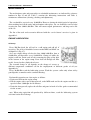
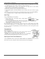
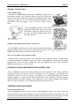
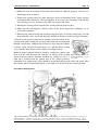
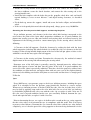
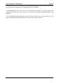
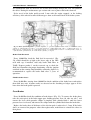
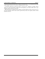
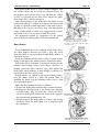
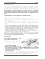
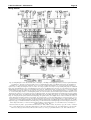
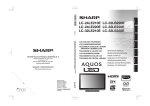
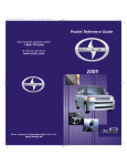
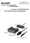
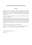
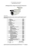
Lada Niva Manual - Maintenance
Page 1
Table of Contents
MAINTENANCE............................................................................................................................2
ENGINE LUBRICATION..............................................................................................................2
Oil Sump.................................................................................................................................2
Oil Filter ................................................................................................................................3
VALVE GEAR ............................................................................................................................4
Valve Clearances......................................................................................................................4
Tensioning the Valve Gear Chain................................................................................................5
FUEL SYSTEM...........................................................................................................................5
Air Cleaner .............................................................................................................................6
Carburettor.............................................................................................................................7
Idling speed adjustment .............................................................................................................7
CRANKCASE BREATHING SYSTEM...........................................................................................9
COOLING SYSTEM ....................................................................................................................9
Coolant ..................................................................................................................................9
COOLING SYSTEM THERMOSTAT.................................................................................................... 10
ALTERNATOR DRIVE BELT............................................................................................................ 10
IGNITION SYSTEM................................................................................................................... 11
Ignition Distributor ................................................................................................................ 11
SPARK PLUGS............................................................................................................................. 12
TRANSMISSION....................................................................................................................... 12
Clutch Fluid Reservoir ............................................................................................................ 12
ADJUSTING THE CLUTCH CONTROL MECHANISM .............................................................................. 12
GEARBOX, TRANSFER CASE. ......................................................................................................... 14
Front and Rear Axles .............................................................................................................. 14
Propeller Shaft Splined Connections and Crosses ........................................................................ 14
Joints of Front Wheel Drive Propeller Shafts............................................................................... 14
HYDRAULIC SHOCK ABSORBERS AND ANTIROLL BAR ......................................................... 14
STEERING GEAR AND WHEELS............................................................................................... 14
Steering Gear Clearances......................................................................................................... 14
Front Wheel Hub Bearings....................................................................................................... 15
Examining the Front Suspension Ball Supports and Steering Rod joints........................................... 17
Tyres.................................................................................................................................... 17
Replacing the Wheels............................................................................................................... 19
Front-End Alignment............................................................................................................... 19
BRAKES.................................................................................................................................. 20
Brake Hydraulic System ........................................................................................................... 20
Brake Fluid Reservoir.............................................................................................................. 21
Flexible brake hoses................................................................................................................ 21
FRONT BRAKES .......................................................................................................................... 21
REAR BRAKES ............................................................................................................................ 23
Bleeding the Brake System........................................................................................................ 24
Adjusting the Free Travel of Brake Pedal.................................................................................... 25
Brake Vacuum Booster............................................................................................................. 25
Parking Brake........................................................................................................................ 25
ELECTRICAL EQUIPMENT ....................................................................................................... 25
Wiring diagram...................................................................................................................... 26
Storage Battery ...................................................................................................................... 27
Alternator ............................................................................................................................. 27
Starter.................................................................................................................................. 27
Voltage Regulator................................................................................................................... 28
Aiming the Headlight Lower Beam ............................................................................................ 28
Replacing the Bulbs ................................................................................................................ 28
Tail lights............................................................................................................................. 29
Fuses.................................................................................................................................... 29
Fuse-Protected Circuits ........................................................................................................... 29
BODY ...................................................................................................................................... 31
Care of Body ......................................................................................................................... 31
Windshield and Headlight Washers............................................................................................ 33
Windshield and Headlight Wipers.............................................................................................. 33
Fastening of Units and Mechanisms to Car Body......................................................................... 33
MAINTENINCE IN LONG-TERM STORIGE................................................................................. 33
Lada Niva Manual - Maintenance
Page 2
MAINTENANCE
The mechanisms, units and parts subject to scheduled maintenance are indicated by reference
numbers in Figs 25 and 26. Table 1 contains the lubricating instructions and Table 2,
maintenance instructions (cleaning, checking and adjustment).
The car should be serviced every 10,000 Km. However, during the initial period of operation,
when working-in of all the units and mechanisms takes place, the car should be serviced after
covering the first 2,000-3,000 Km. This will ensure superb performance and long service life
of the car.
The list of the tools and accessories delivered with the car for Owner’s services is given in
Appendix 3.
ENGINE LUBRICATION
Oil Sump
Every 500 Km check the oil level in a cold engine and add oil, if
necessary. The oil level should be between marks MIN and MAX on
oil dipstick 1 (Fig. 27).
On a new engine change oil after the first 2,000-3,000 Km, then at
10,000 Km and thereafter every 10,000 Km. Change oil while the
engine is still hot. Drain used oil after removing the plug of the hole
in the bottom of the engine sump. Pour fresh oil through oil filler
neck 2, located on the cylinder head cover.
The seasonal change of oil depends on the change of season as
different temperature conditions call for the employment of different grades of oil (see
Appendix 2).
Every 30,000 Km wash the lubricating system. Wash the system earlier only when sticky
gum deposits accumulate on the camshaft housing.
Perform this operation on a hot engine as follows:
• Drain used oil from the engine sump.
• Fill the engine with a special detergent oil, to the MIN mark and let the engine run idle at a
speed of about 1,000 rpm for 10 minutes.
• Drain the detergent oil, replace the oil filter and pour in fresh oil of the grade recommended
for the season.
note. When using equivalent oils produced by different firms, wash the lubricating system
each time before the oil change.
Lada Niva Manual - Maintenance
Oil Filter
Every 10.000 Km replace the filter. Do it after the first 2,0003,000 Km on a new car. To replace the filter unscrew it from the
cylinder block (pig. 28). Screw the new filter in place only handtight.
Page 3
Lada Niva Manual - Maintenance
Page 4
VALVE GEAR
Valve Clearances
Every 10.000 Km and also in case of abnormal knocking in the
valve mechanism, check clearances A (Fig. 29) between the
cams and valve rockers which should be 0.15 mm on a cold
engine both for the intake and exhaust valves. On a new engine
perform this operation after the first 2,000-3,000 Km upon
checking and tightening the fasteners of the cylinder head,
camshaft bearing housing and intake and exhaust manifolds.
Loosen the cylinder head bolts preliminarily through about
30" each and then tighten them according to the sequence
shown in fig. 30.
Figure 30 - Sequence of tightening
cylinder head bolts
Valve Gear
A - Valve rocker to cam clearance 1 cam, 2 - valve rocker, 3 - valve oil
deflecting cap, 4 - valve, 5 - rocker
adjusting bolt, 6 - adjust bolt locknut.
Tighten bolts 1 through 10 to a torque of 115 NÆm(11.5 kg Æm),
and bolt 11 to a torque of 38 NÆm (3.8 kg Æ m).
Tighten the nuts of the camshaft
bearing housing by applying a torque
of 22 NÆm (2.2 kg m) according tothe
sequence shown in pig. 31.
Fig 31. Sequence of tightening
camshaft bearing housing nuts
To adjust the valve clearances, proceed as follows:
• Remove the cylinder head cover with its gasket; if necessary,
first remove the heater air intake box;
• Rotate the crankshaft clockwise to align mark A (Fig. 32) on
the sprocket with mark B on the camshaft housing; in this case
the piston of the No. 4 cylinder will be on TDC at the end of
the compression stroke, and both valves will be closed
• Adjust the rocker-to-cam clearances of the exhaust valve on
the No. 4 cylinder (8th cam) and of the intake valve on the No.
3 cylinder (6th cam); for this purpose, loosen locknut 2 (Fig.
33) and rotate adjusting bolt 1 to set the required clearance,
using a flat feeler gauge inserted between the cam and the
rocker (the feeler gauge should move in this case with a slight
biting)
• Holding bolt 1 in this position with a wrench, tighten locknut
2 by applying a torque of 52 NÆm (5.2kg Æm) and recheck the
clearance
• Turning the crankshaft each time through hall a revolution,
adjust the clearances of other valves, following the sequence
given in Table 3 below.
Fig 32.
Setting No. 4 Cylinder piston in TDC
Fig 33. Adjusting valve clearances:
1- adjusting bolt, 2- adjusting bolt
locknut
Lada Niva Manual - Maintenance
Page 5
Table 3 - Sequence of Valve Clearance Adjustment.
Crankshaft
angle
degrees
No of cylinder in which piston is on
TDC
at end of compression stroke
0
180
360
560
4
2
1
3
Valves under adjustment
exhaust
intake
Cylinder
No.
Cam No.
Cylinder
No.
Cam No.
4
2
1
3
8
4
1
5
3
4
2
1
6
7
3
2
• Reinstall the cylinder head cover with its gasket. Adjustment over, check the tightening
torque of the crankshaft jaws, which should be 122 NÆm (12.2 kg Æ m).
Tensioning the Valve Gear Chain
Every 10.000 Km, adjust the tension of
timing chain 2 (Fig. 34). Do it on a new car
after the first 2,000- 3,000 Km. For this
purpose, loosen retaining nut 7 and turn the
crank- shaft through 1-1~5 revolutions in the
direction of its normal rotation. In this case
spring 10 actuates shoe 6 through plunger 11
and automatically sets the required chain
tension. Adjustment over, tighten nut 7.
Adjust chain tension also in case of excessive
operation noise in the valve gear.
Fig 34. Valve Gear Drive. 1 - camshaft sprocket, 2 - chain, 3 dampener, 4 - oil pump drive shaft sprocket, 5 - crankshaft
sprocket, 6 - chain tensioner shoe, 7 tensioner rod retaining nut, 8 retainer, 9 - tensioner adjusting rod, 10 - plunger spring, 11 tensioner plunger
FUEL SYSTEM
Lada Niva Manual - Maintenance
Page 6
Air Cleaner
Every 10.000 Km replace filter element 3 (Fig. 35); to this end
unscrew nuts 1 and remove cover 2. When driving on extremely dusty
roads, replace the filter element every 5,000 Km.
Seasonal adjustment of the air cleaner is required for delivery of fresh
or warm air (warmed by the exhaust manifold). If the average ambient
temperature in the season is below 15 "C, slightly pull and then shift
the handle 5 of the gate on the housing of thermo-regulator 4 in the
upper position (HOT) and if the average temperature is above 15 "C,
shift the handle to the lower position (COLD).
Figure 35. Air Cleaner 1- nut, 2cover, 3- filter, 4- thermo-regulator, 5handle
Lada Niva Manual - Maintenance
Page 7
Carburettor
Every 10.000 Km (and also after the first 2,0003,000 Km if the car is new), wash the carburettor
fuel filter and the fuel pump filter with gasoline and
blow them out with compressed air.
Every 20,000 Km clean the carburettor from the
inside, wash it with gasoline or benzene and blow
out with compressed air. When cleaning the
Fig. 36.Adjusting Fuel Level In Carburettor
calibrated orifices of the jets, use a wooden stick or Float Chamber: 1- carburettor upper body, 2 valve rest, 3 - stop, 4 - needle valve, 5match with a pointed end wetted with acetone. Do needle
ball, 6- pull-back yoke, 7 arm, 8 lounge, 9not use wire, even soft, not to disturb the float, l0- gasket.
dimensions and finish of the orifices. When screwing the jets in or out, avoid damaging the
thread in the holes.
Check and, if necessary, adjust the fuel level in the float chamber and the float travel, for
which purpose.
• Make sure that the mass of float 9 (Fig. 36) complete with arm 7 is 12+1 g, the float has no
holes or dents, and can freely rotate on its pin.
• Make sure that seat 2 of needle valve 4 is tightened reliably and that damper ball 5 built
into needle valve 4 does not stick
• Set upper body 1 vertically so that the fuel inlet union is directed upwards, the needle
valve is closed, and float tongue 8 lightly contacts the needle valve ball.
• With the parts in this position, measure the distance between the float and the surface of
gasket 10 which fits the upper body; the distance should be 6.5 mm
• Change the position of the tongue, if necessary, to obtain the required distance; the tongue
must be perpendicular to the valve axis, and the contacting surface of the tongue should
have no defects that may cause sticking of the valve.
• Check the float travel which should be 8 mm, changing the position of stop 3, if necessary.
• Check that pull-back yoke 6 of the needle valve does not interfere with free travel of the
valve.
• Reinstall the carburettor upper body after making sure that the float is free to move
without brushing against the chamber walls.
Note. When replacing the needle valve, also replace the gasket between the seat and the upper
body.
Idling speed adjustment
Every 10.000 Km (and also after the first 2,0003,000 Km if the car is new), adjust the minimum
idling speed of the engine. Have this adjustment
done at a service station. The Owner is allowed
only to carry out fine adjustment of the engine
idling speed within the range permitted by idle
speed screw limiting bushing 1 (Fig. 37) and by
idle mixture screw limiting bushing 2. Attempts to Fig 37. Idling system adjustment screws: 1- Idle
speed screw limiting bushing, 2- idle mixture screw
turn the bushings through a larger angle will limiting bushing.
destroy them. In this case the Manufacturer bears
no responsibility for excessive content of carbon monoxide (CO) in the exhaust gases and for
excessive fuel consumption.
Lada Niva Manual - Maintenance
Page 8
Perform the fine adjustment with the engine warmed-up, valve clearances adjusted, and a
spark advance angle set properly. Proceed as follows.
• Start the engine and turn idle mixture screw limiting bushing 2 all the way out.
• Using idle speed screw limiting bushing 1, set the engine speed within 850-900 rpm
Lada Niva Manual - Maintenance
Page 9
Check the engine idling performance. For this purpose, abruptly depress and release the
accelerator pedal; in this case the engine speed should increase smoothly without missing. The
engine should not stall when the idling speed is reduced to minimum. If the idling speed fine
adjustment fails to ensure normal running of the engine without missing, apply to a service
station for a qualified help.
CRANKCASE BREATHING SYSTEM
Every 20.000 Km clean and wash with gasoline the hoses of the crank- case breathing
system, the shut-off valve on the carburettor throttle valve shaft, and the flame arrester
located in the exhaust hose running from the engine to the air cleaner.
COOLING SYSTEM
Coolant
The cooling system of the cars leaving the plant is filled with
special fluid A-40M. This fluid is an ethylene glycol mixture with
a freezing point of minus 40"C and anticorrosive, antifoaming and
antiscaling properties. It needs no replacement within a period of
three years. Therefore, care of the cooling system during this
period consists only in checking at regular intervals the fluid level
in the expansion tank.
The fluid level should always be 3-4 cm above the MIN mark Fig 38 Cooling system expansion tank
(Fig. 38). Check the fluid level on a cold engine only, since when
the engine is hot the level may rise significantly; expansion of the fluid volume may also take
place immediately after engine shutdown.
If the fluid level is below the MIN mark, replenish the expansion tank with fluid of the same
grade. If the coolant level drops constantly and frequent replenishments are required, check the
cooling system for leakage and eliminate the trouble. In an emergency the cooling system may
be filled with clean water. In this case proceed as follows:
• Cool the engine.
• Remove the caps from the radiator and expansion tank.
• Pour water into the radiator (keep pouring water until it starts flowing out of the radiator
filler neck).
• Reinstall the radiator cap.
• Add water into the expansion tank until its level is 3-4 cm above the MIN mark.
• Reinstall the expansion tank cap.
In cold seasons if water has been added into the cooling system and before placing the car in
motion, warm the engine up to 85-90"C to make the fluids mix. Bear in mind that water added
into the cooling system raises the freezing temperature of the mixture; therefore, per- form the
necessary repairs of the cooling system at the first opportunity and fill it with the coolant of
the prescribed grade.
Lada Niva Manual - Maintenance
Every three years or every 60,000 Km (whichever comes
first), flush the cooling system and fill it with fresh coolant.
Drain coolant from the system through two drain holes 1 and
2 (Fig. 39), one of which is located in the radiator bottom tank
and the other one in the cylinder block at the left side. In doing
so shift the heater cock control lever to the right most
position.
Page 10
Fig 39. Cooling system drain holes. 1- drain hole
in radiator bottom, 2- drain hole in cylinder block.
For screwing the radiator drain hole plug in or out, use two wrenches; one to keep in place
the plug union soldered into the radiator tank, and the other to screw the plug in or out. After
draining the coolant completely from the system through the above holes, remove the coolant
remaining in the expansion tank and hose connecting the tank to the radiator by disconnecting
the hose from the expansion tank or by raising the tank proper to a required height.
To flush the cooling system, proceed as follows.
• Fill the system with clean water, start the engine and run it until the bottom tank of the
radiator gets warmed and, with the engine idling, drain water through the radiator and
cylinder block drain holes.
• Let the engine cool down, refill the system with clean water and repeat the above
operation.
After the flushing pour coolant into the cooling system. If the coolant of the specified grade
is not avail- able, it is permissible (at ambient temperatures above zero) to use clean water, as
soft as possible to avoid heavy scale deposition which leads to engine overheating under
normal operating conditions. When using hard water, flush the cooling system twice a year
with special descaling agents.
If an aluminium radiator is in- stalled in the car do not use water in the cooling system as
water affects corrosion resistance of the radiator.
Cooling System Thermostat
Every 20.000 Km and also in case of abnormal temperature
of the engine (overheating under normal operating conditions
or excessively long warm-up period after starting), check
thermostat 4 (Fig. 40) for normal functioning. A simple check
is the hand- feeling of the thermostat directly on the car.
Upon starting the cold engine with the thermostat serviceable, the bottom tank of the radiator starts getting warm as
soon as the coolant temperature is 80-85 "C.
Alternator Drive Belt
Fig 40. Checking tension of Alternator
drive belt. 1- nut, 2- nut of alternator joint
pin, 3- alternator, 4- thermostat, 5- water
pump, A- belt deflection.
Every 10.000 Km (and after the first 2,000-3,000 Km if the car is new), check the belt for
tension. Normal deflection A (Fig. 40) is 10-15 mm if a force of 100 N (10 kg) is applied.
To increase the belt tension, proceed as follows.
• Loosen nut 1 that fastens the alternator to the adjusting arm.
Lada Niva Manual - Maintenance
Page 11
• Loosen nut 2 of the alternator joint pin.
• Shift alternator 3 away from the engine and tighten the fastening nuts.
Avoid over tightening the belt so as not to overload the bearings of alternator 3 and water
pump 5.
IGNITION SYSTEM
Ignition Distributor
Every 10,000 Km:
1. Check the working surfaces of breaker contacts 3 (Fig.
41). In case of heavy transfer of metal from one
contact point to the other, dress them with a flat
barette file. Do not eliminate completely the crater on
the breaker arm contact point. Check and, if necessary,
dress the contacts in the distributor cap and on the
rotor.
2. Use a piece of clean, gasoline- soaked chamois leather
or some other lint-free material to clean the breaker
41. Ignition distributor. 1- noise resistor
contact points, the rotor, and the outer and inner Figure
suppressor, 2- rotor, 3- breaker contacts, 4surfaces of the distributor cap.
screw, 5- slot, 6- terminal, 7- spring catch, 89- scale, 10- bracket, 11- nut, 12- body,
3. Check the breaker point gap which should be 0.4+0.05 capacitor,
13- vacuum spark timer, 14- lubricator, 15- cam
mm, for which purpose.
• Shift the gearshift lever into the neutral.
• Apply the parking brake;
• Rotate the crankshaft with the starting crank to set cam 15 in the position at which the
breaker contacts are wide open.
• Check the gap with a feeler gauge; if the gap differs from the rated value, loosen screws 4
and, using a screwdriver inserted into special slot 5, shift the breaker con- tact post as
required; adjustment eve, tighten screws 4.
4. Check ignition timing, for which purpose
• Connect one end of the wire of a 12-V test lamp to terminal 6, and ground its other end.
• Turn on the ignition and slowly rotate the crankshaft with the starting crank; with the
ignition set properly, the test lamp should come on when mark 4 (Fig. 42) on the
crankshaft pulley is aligned with mark 2 on the timing gear cover, and the contact of rotor 2
(Fig. 41) should be opposite the contact of the No. 1 cylinder on the distributor cap.
5. If the marks are not aligned at the moment the test lamp
comes on, adjust the ignition timing as follows.
• Rotate the crankshaft with the starting crank to set it in
the position at which the rotor contact faces the contact of
the No. 1 cylinder on the distributor cap, and mark 4 (Fig.
42) is aligned with mark 2 (in this position the piston of
the No. 1 cylinder will be 5" before TDC as measured in
crankshaft degrees);
• Loosen nut 11 (Fig. 41) and turn distributor body 12
clockwise until the breaker points are closed.
Fig 42. Timing marks on pulley and valve
gear drive cover. 1- 10o, 2- 5 o, 3-0 o, 4mark on pulley
Lada Niva Manual - Maintenance
Page 12
• Slowly rotate the distributor body counter-clockwise until the test lamp comes on; in doing
so, slightly press the rotor counter- clockwise to take up clearances.
• Stop the distributor body exactly at the moment the test lamp comes on (the breaker
contact points are at the beginning of opening phase).
• Holding the distributor body in this position, tighten nut 11.
• Switch off the ignition, install the distributor cap on its body, and secure it with two spring
catches 7.
On a new car, check the breaker point gap and ignition timing after the first 2,000-3,000 Km.
Every 20.000 Km deliver 2-3 drops of engine oil into the hole of lubricator 14.
Spark Plugs
Every 10,000 Km proceed as follows:
1. Using gasoline and a stiff brush, remove carbon deposit
from the spark plugs.
2. 2. Check the spark plug gap with a round wire feeler gauge.
Fig 43. Checking spark plug gap
The gap should be 0.5-0.6 mm (Fig. 43); the gap must be
adjusted only by bending the side electrode.
Every 20,000 Km replace the spark plugs with new ones. For re- liable starting of the engine
at low sub-zero temperatures, it is recommended to replace the long-used spark plugs with
new ones, even if the used spark plugs are still serviceable; they can be used again in warm
seasons of the year.
TRANSMISSION
Clutch Fluid Reservoir
Every 10,000 Km check fluid level in the reservoir (Fig. 44) and
replenish, if necessary, to the lower edge of the filler neck.
Add HeBa (Neva) or Tomb (Tom) brake fluid only. It is recommended
to change the brake fluid with fresh one after five years of service.
Adjusting the Clutch Control Mechanism
Every 30,000 Km (and also after the first 2,000-3,000 Km and 10,000 Km if the car is new)
check and, if necessary, adjust the clutch control mechanism for which purpose.
Lada Niva Manual - Maintenance
Page 13
Check clearance between pushrod 3 (Fig. 45) and piston 2 of master cylinder 1 which should
be 0.1-0.5 mm. The clearance corresponds to the travel of pedal 5 through 0.4-2 mm and it is
adjusted with stop 4.
Check free travel of pushrod 6 of
operating cylinder 10 which should be 4-5
mm. Pushrod free travel is adjusted with
nut 8 after loosening locknut 9.
Adjustment over, tighten locknut 9.
Upon completion of the above
adjustments free travel of the clutch pedal
before the beginning of clutch release
should be 25-35 mm. Check the clutch
pedal free travel also after the bleeding of
the hydraulic control system. Presence of
air in the system is indicated by the
45. Adjusting Clutch control mechanism. 1- Clutch master
spongy pedal and incomplete release of the Fig
cylinder, 2- pushrod piston, 3- pushrod, 4- pedal travel stop, 5- clutch
clutch (clutch drags). Bleed the system pedal, 6- operating cylinder pushrod, 7- clutch release fork, 8- nut, 9through the union of operating cylinder 10 locknut, 10- operating cylinder.
in the same way as the brake system.
Lada Niva Manual - Maintenance
Page 14
Gearbox, Transfer Case.
Front and Rear Axles
After the first 2000-3000 Km and every 30.000 Km, change oil in
the gearbox, transfer case, and front and rear axles. Do it right after
the trip, when oil is still hot. Drain used oil through the holes closed
with plugs 2 (Figs. 46, 47, 48, 49). Pour fresh oil through the level
check holes closed with plugs 1, up to the lower edges of these
holes.
Every 10,000 Km check oil level which
should reach the lower edges of the level
check holes. Check be- fore the trip to be
sure that all oil has dripped down from
the walls and gears.
Fig 49. Rear Axle. 1- check hole
plug, 2- drain hole plug.
Fig 46. Gearbox. 1- check hole
plug, 2- drain hole plug
Fig 47. Transfer Case. 1- check
hole plug, 2- drain hole plug
Propeller Shaft Splined Connections and Crosses
Every 10.000 Km deliver grease to the splined connections through
the grease fittings and grease-gun the crosses with grease No. 158 or
cDMOn-ZY till fresh grease shows up under the seals.
Fig 48. Front Axle. 1- check hole
plug, 2- drain hole plug
Joints of Front Wheel Drive Propeller Shafts
While in service, care of the joints of the front wheel drive propeller shafts is confined only
to regular checking the condition of protective boots. A damaged boot should be immediately
replaced with a new one upon washing the joint and changing the grease. This operation
should be performed at a service station.
HYDRAULIC SHOCK ABSORBERS AND ANTIROLL BAR
Every 30.000 Km check the shock absorbers for serviceability. If the shock absorbers
operation becomes less efficient, which is manifested by slow damping of oscillations (3-4
oscillations) of the car body on crossing a road bump, or by unusual knocking in the shock
absorbers, apply to a service station. Pay attention also to the condition of shock absorber
rubber bushings and rubber cushions of the antiroll bar. If the rubber bushings and cushions
show any signs of damage or age-hardening, replace them with new ones.
STEERING GEAR AND WHEELS
Steering Gear Clearances
Every 20,000 Km (and also after the first 2,000-3,000 Km if the car is new), check the
steering wheel for play which should not exceed 18-20 mm measured on the wheel rim with
the wheels in the straight ahead position and with normal clearances in the steering gear. If the
steering wheel play exceeds this value, perform an overall check of the steering gear:
Lada Niva Manual - Maintenance
Page 15
1. Make sure that the bearings of the front wheel hubs are adjusted properly and the tyre
inflation pressure is normal.
2. Turning the steering wheel in either direction, check for knocking in the joints, steering
mechanism and connections. Check and tighten, if necessary, the fastenings of the pitman
arm, steering gear case, brackets of the idler arm and steering shaft.
3. Rocking the steering wheel hand-feel the steering rod ball joints for play.
4. Make sure the ball supports and the joints of the front suspension wishbones are in
serviceable condition.
5. Eliminate the faults detected and check steering wheel play. If steering wheel play exceeds
the permissible value, check and adjust the following clearances in the steering mechanism:
Clearance in the worm bearings that is found by axial movement of the
steering shaft while turning the steering wheel leftward and rightward
through a small angle; eliminate the clearance by decreasing the number
of shims 3 (Fig. 50) placed between the case and the thrust bearing
cover until the shaft rotates easily without axial displacement;
Roller-to-worm backlash which is found by rocking the pitman arm
head, with the rods disconnected, with the car wheels in the straight Fig 50. Adjusting clearances in
mechanisms. 1- screw, 2ahead (neutral) position; eliminate backlash by turning in screw 1, steering
nut, 3- shims
with nut 2 loosened and the pitman arm in the neutral position;
adjustment over, tighten nut 2; there should be no backlash between the roller and worm when
the steering wheel is turned through 30" to the right or to the left from the neutral position.
Front Wheel Hub Bearings
Fig. 51. Front Wheel: 1 - brake disc; 2 - hub; 3 - outer roller bearing; 4 - outer seal protective ring; 5 - outer seal; 6 tapered bushing; 7 - hub nut; 8 - hub cap; 9 - propeller shaft drive end; 10 - outer seal demounting ring; 11 - inner
roller bearing; 12 - inner seel demounting ring; 13 - inner seal; 14 - inner real protective ring; 15 - steering knuckle;
Lada Niva Manual - Maintenance
Page 16
16 - lower wishbone ball support; 17 - lower wishbone; 18-propeller shaft; 19-upper wishbone ball support; 20 shims
Every 10.000 Km (and also after the first 2,000-3,000 Km if the car is new), check and
adjust, if necessary, the clearances in the front wheel hub bearings. For this purpose, proceed
as follows:
• Place the car on a level ground, apply its parking brake, loosen the wheel fastening nuts,
jack up the wheel and remove it, having turned off the wheel nuts
• Remove hub cap 8 (Fig. 51), secure a device with an indicator on steering knuckle 15 so
that the indicator finger contacts the end face of hub 2 near the tapered hole;
• Pull the hub to yourself by hands, and set the indicator pointer to zero;
• Measure the clearances in the hub bearings, for which purpose push the hub axially away
from your- self. If in this case the indicator readings exceed 0.15 mm, adjust clearances in
the bearings in the following way;
• Remove the indicator, screw off nut 7 and replace it with a new one;
• Tighten nut 7 to a torque of 20 NÆm(2 kg m), rotating the hub in both directions;
• Loosen the nut and retighten it to a torque of 7 N Æm (0.7 kg Æm); then, screw it off
through 20-25";
• Install the indicator and measure clearances in the bearings. If clearances exceed 0.07 mm,
repeat the adjustment. If clearances are within 0.01-0.07 mm, fix nut 7 by staking the dents
on the nut shoulder into the slots on drive end 9 of the propeller shaft.
• Remove the device with the indicator, install cap 8, fasten the wheel, jack down the car, and
tighten the wheel nuts all the way home.
Every 20.000 Km. replace grease in the bearings of the front wheel hubs. For this purpose
proceed as follows.
• Remove the wheel, disconnect the brake calliper from steering knuckle 15, and take it off
brake disc 1;
• Remove hub cap 8, screw off nut 7, take out tapered bushing 6 and remove hub 2 complete
with brake disc 1;
• Place a support under lower wishbone 17 and screw off the nuts securing ball support 16
to the wishbone;
• Disconnect the shock absorber from the lower wishbone and the side steering rod from the
arm of steering knuckle 15;
• Shift propeller shaft 18 to- wards the front axle as far as it will 90;
• Turning steering knuckle 15 about upper wishbone ball support 19, remove the former
from the propeller shaft drive end;
• Use the puller to remove the cones of bearings 3 and 11 with demounting rings 10 and 12
and seals 5 and 13 from the steering knuckle space. Mark the bearing cones in order to
reinstall the cones in their proper places during the assembly;
• Remove the used grease and wash with kerosene the inner space of the steering knuckle,
outer and inner spaces of the hub, propeller shaft drive end, and bearing cones;
• Pack 40 g of fresh grease nHTon-24 into the bearing cages, apply a uniform layer of grease
to the steering knuckle spaces between the bearings, and lubricate the splines of the
propeller shaft drive end;
• Reinstall the bearing cones and demounting rings, and press- fit the seals;
Lada Niva Manual - Maintenance
Page 17
• Mount the steering knuckle on the propeller shaft drive end, connect the ball support to
the lower wishbone, secure the shock absorber, and connect the side steering rod to the
steering knuckle arm;
• Install the hub complete with the brake disc on the propeller shaft drive end, and install
tapered bushing 6; screw on new hub nut 7 and adjust bearing clearances, as described
above;
• Fit the hub cap, remove the support, install and secure the brake calliper, and reinstall the
wheel.
• If the car is frequently driven on bad roads (deep mud), change grease every 10,000 Km.
Examining the Front Suspension Ball Supports and Steering Rod joints
If tyre inflation pressure and clearance in the front wheel hub bearings correspond to
rated values, the joints of the front wheel suspension wishbones are in good condition,
pitman arm, steering gear case, idler arm brackets and steering shaft are fastened securely,
adjustment of the steering gear fails to ensure normal play of the steering wheel, check
following:
the
the
but
the
1. Clearances in the ball supports. Check the clearances by rocking the hub with the front
wheel suspension jacked up and wheels braked (to exclude the effect of clearances in the hub
bearings). If the steering knuckle displacement at the level of the ball pin sphere relative to the
wishbones exceeds 0.8 mm, replace the ball support.
2. Clearances in the steering rod joints. Determine the clearances by the method of mutual
displacement of the steering rods when turning the steering wheel.
Premature wear of the ball joints is generally caused by damaged protective rubber boots
which allow ingress of water and dust into the joints. If the boot is in good condition, the
service life of the joints is practically unlimited. Therefore, check the protective rubber boots
for condition at regular intervals, and replace them with new ones even if the slightest damage
is detected, after making sure that the ball joints are serviceable and that there is enough grease
U1P6-4in
Tyres
Every 100 Km use a tyre pressure gauge to check tyre inflation pressure, including the spare
wheel. It is advisable to have the pressure gauge periodically checked at a service station.
Whenever tyre inflation pressure is checked, check the tube valve for air leaks (best of all it
may be done by applying soap suds to the valve inlet hole). In case of air leak- age (indicates
by air bubbles) tighten the tube valve core with the valve cap, or replace it with a new one. If
the valve core is in good condition, but-the tyre gets constantly deflated, demount the tyre,
check and repair the tube, or replace it with a new one.
Prior to demounting the tyre, use a piece of chalk to make a mark on the tyre casing opposite
the tube valve with a view to mount the tyre in compliance with this mark. This is necessary
to preserve wheel balance. Demount the tyre from the wheel disc with the tyre tube deflated
completely; see to it that the part of the casing opposite to the zone being demounted is in the
Lada Niva Manual - Maintenance
Page 18
wheel rim well. Use tyre irons for the de- mounting/mounting jobs. The di- stance between the
tyre irons when catching the tyre bead should not exceed 150 mm.
Upon installation of new tyres, be sure to check the wheel balance at a service station. It is
not advisable to drive the car on new tyres at a speed greater than 100 km/h during the first
500 Km.
Every 10.000 Km interchange the wheels as shown in Pig. 52 to ensure uniform wear of
tyres. If abnormal vibrations in motion are detected, check wheel balance.
Lada Niva Manual - Maintenance
Page 19
Replacing the Wheels
To replace a wheel, proceed as follows:
Place the car on a level ground and apply the parking brake;
Prepare the jack, tyre pump, tools bag and spare wheel;
Use the combination wrench to slacken the wheel nuts one Fig 52. Wheel rotation diagram
revolution;
Insert the jack arm into the socket nearest to the wheel being
replaced (Fig. 53), and rotate the jack handle until the wheel
clears the ground (the jack should not sink in the ground when
the car is being raised);
Unscrew the wheel nuts and remove the wheel. Install the Fig 53. Jacking up car for
spare wheel and uniformly tighten the wheel nuts;
replacement of wheels.
Lower the car onto the wheels, and withdraw the jack;
Tighten the nuts to a torque of 70-90 NÆm (7-9 kg m), check tyreinflation pressure and bring
it to normal;
Stow the tools and the spare wheel under the hood, and secure them as shown in Fig. 54.
Fig
54.
Stowage
and
fastening of
tools and
accessories. 1, 6, 8, 11elastic straps, 2- jack, 3starting crank, 4- tyre irons, 5inspection lamp, 7- tools bag,
9- wing nut, 10 spare wheel,
12 air pump
Front-End Alignment
Every 20,000 Km (and also after the first 2,000-3,000 Km if the car is new) as well as in case
of rapid and irregular wear of the front wheel tyres and impaired steering of the car, check the
front-end alignment. It is advisable that this operation is performed at a service station
equipped with a precision optical stand ensuring high-accuracy checking and front-end
alignment. Given below is a method, though less accurate, of checking only the wheel camber
and toe-in by the Owner himself, on condition that the following requirements are met:
Tyre inflation pressure is normal;
Radial and axial runout of the front wheel rims does not exceed 3 mm;
End play in the front wheel bearings does not exceed 0.15 mm;
Backlash in the steering worm- to-roller mesh ensures a steering wheel play not exceeding 5";
there is no clearance between the idler arm shaft and shaft bushings;
The rubber elements in the joints of the front suspension wish- bones have no ruptures and
ultimate distortions;
Shock absorber rods are not jamming; there are no excessive clearances in the steering rod ball
joints and in the ball supports of the front suspension wishbones.
Check the wheel alignment with the car in the running order, with a load of 3,200 N (320 kg)
which roughly corresponds to the weight of four persons plus 400 N (40 kg) of luggage in the
Lada Niva Manual - Maintenance
Page 20
luggage compartment. Place the car on a flat level ground and set the front wheels in the
position that corresponds to the straight-ahead motion.
To stabilise the position of the suspension units, exert pressure on them by pushing down
first the rear and then the front bumpers for 2-3 times, applying a force of about 400-500 N
(40-50 kg). To determine wheel camber, measure distance C (Fig. 55) between the wheel rim
and the set square. Then roll the car to turn the wheels through 180", and measure distance D.
Camber is correct if distance D is 1-5 mm greater than distance C. Camber is adjusted by
changing the number of shims 20 (Fig. 51) between the upper wishbone shaft and the cross
member. Check and adjust toe-in only after checking and adjusting the wheel camber.
Fig 55. Checking front end alignment
To determine toe-in, measure distance A (Fig. 55) between the corresponding points on the
front wheel rims. Then roll the car to turn its wheels through 180" and measure distance D is
1-5 mm greater than distance C.
Camber is adjusted by changing the number of shims 20 (Fig 51) between the upper
wishbone shaft and the cross member.
Check and adjust toe-in, measure distance A (Fig 55) between the
corresponding points on the front wheel rims. Then roll the car to
turn its’ wheels through 180 degrees and measure distance B. Toe-in is
correct, if the first dimension is 2-4 mm greater than the second one.
Toe-in is adjusted by changing the length of side steering rods 3 (Fig.
56). For this purpose loosen clamps 2 and turn adjusting sleeves 1 Fig 56. Adjusting length of side
steering rods. 1- sleeve, 2- clamps, 3
through the same number of revolutions in the opposite directions, side steering rod, 4- steering rod end.
thus screwing the sleeves on or off and changing the length of the side
steering rods. Adjustment over, tighten clamps 2 to a torque of 19 N Æm (1.9 kg Æm) so that
their slots face down and their ends, after tightening, do not touch each other.
Camber and toe-in can be also checked and adjusted, though less accurately, with the car
unloaded. In this case wheel camber D-C should be from -1 to +3 mm, and toe-in A-B should
be 4~1 mm.
BRAKES
Brake Hydraulic System
The brake system of the car is given in Pig. 57. Prior to servicing the brake system, clean each
brake of dirt, wash it with warm water and dry with compressed air.
Never use gasoline, diesel fuel, trichloroethylene or other mineral solvents for the purpose
since they attack the cups and seals of the hydraulic cylinders.
The surfaces of the brake linings should be clean, with no traces of dirt or lubricant. Soiled
linings should be cleaned with a wire brush and washed with white spirit. If the pads or linings
Lada Niva Manual - Maintenance
Page 21
are contaminated with oil, check for oil or brake fluid leakage through the seals and eliminate
the defect. During the maintenance ope- rations take care to protect the brakes from oil.
If free travel of the brake pedal exceeds 5 mm with the engine stopped, or the braking
efficiency of the wheels becomes different, per- form an all-round check of the brake system.
Fig. 57. Brake System Diagram: 1 - pressure regulator; 2 - pressure regulator torsion lever; 3 - rear brake wheel
cylinder; 4 - parking brake rear cable; 5 - rear cable equaliser; 6 - parking brake front cable; 7 - parking brake lever; 8 brake pedal; 9 - vacuum booster; 10 - brake fluid reservoir; 11 - primary brake circuit; 12 - secondary brake circuit; 1 3
- (rent disc brake cylinder block; 14 - brake master cylinder; (5 - T-piece
Brake Fluid Reservoir
Every 10,000 Km check the fluid level in reservoir 1 (Fig.
58), which should be as high as the lower edge of the filler
neck with cap 2 installed. Add only brake fluid Hesa or
ToML. Depress pusher 3 on the reservoir cap to check the
fluid level transmitter for proper functioning; with the ignition
switched on the warning lamp should be constantly alight. It is
recommended to replace the brake fluid after 5 years of
operation.
Flexible brake hoses
Fig 58. Brake fluid reservoir. 1fluid reservoir, 2- cap, 3- pusher,
4- inspection lamp socket
Every 10,000 Km, starting from 30,000 Km check condition of the brake hoses and replace
them with new ones, if minor cracks are detected on the sheathing or bulges appear on the
hose when the brake pedal is pressed.
Front Brakes
Every 10.000 Km check the condition of brake shoes 6 (Fig. 59). To remove the brake shoes
take out cotter pin 8 in the brake upper part; holding pressure lever 10, take out axle 7 and
remove the lever; shift upwards calliper 4 complete with cylinder block 1 until the lower
pressure lever is released, and remove the calliper with the cylinder block from the brake disc.
Replace the brake shoes if thickness of the friction pads is reduced to 1.5 mm. If the brake
shoes are removed for purposes other than replacement, mark them to reinstall the shoes in
their places.
Lada Niva Manual - Maintenance
Page 22
Before installation of the brake shoes, make sure that brake disc 5 is not damaged nor deeply
scored. Replace the disc if it is worn to a thickness below 9.5 mm.
To install the brake shoes push the pistons as deep into the cylinders as possible. When
doing so see that the protective rubber seals of the pistons are in their sockets and are not
damaged; replace the seals, if necessary.
When the pistons are pushed into the cylinders, the brake fluid level in the reservoir rises. To
prevent overflowing, remove the reservoir cap and timely remove the required amount of fluid
from the reservoir.
Lada Niva Manual - Maintenance
Then install brake shoes 6, fit the calliper complete with
the cylinder block, and fix it with the pressure levers; for
this purpose press off the lower lever and shift the calliper
so that it is pressed by the lower lever; install the upper
lever, insert axle 7 and fit cotter pin 8.
Upon the installation of the brake shoes the brake system
needs no bleeding. It is sufficient to depress the brake pedal
in order to attain the normal operation of the brake system.
Bleeding of the system is necessary only after disassembly
of the cylinder block, or when air is trapped in the system;
use bleeder valves 3 to evacuate air from the system.
The adjustment required to compensate for the natural
wear of the brake friction pads is effected automatically.
Rear Brakes
Every 20.000 Km check the condition of the brake shoes
for which purpose unscrew two bolts 1 (Fig. 60), insert
them into holes A and screw them in until brake drum 2 is
moved off its place.
Check the condition of brake shoes 2 (Fig. 61) with friction
linings 1 and inspect the working surface of the brake drum.
If the brake shoes are broken or distorted which prevents
uniform shoe-to-drum contact and reduces efficiency of
braking, replace the shoes with new ones. Also replace the
brake shoes when thickness of their linings is reduced to 2
mm. Replace the shoes in pairs only.
If deep notches are formed on the drum working surface,
have the drums turned in a lathe and ground. Prior to
installing the drum, coat the mounting surface with a thin
layer of graphite grease.
Adjust the shoe-to-drum clearance as follows:
• Depress the brake pedal until the shoes contact the drum;
• Keeping the shoes pressed to the drums, turn adjusting
eccentric heads 1 (Fig. 62) until they contact the shoes;
release the brake pedal and turn the heads in the opposite
direction through approximately 10";
• Sharply depress the brake pedal 3-4 times and, having
released it, check the brake drum; if it is jammed, repeat
the adjustment.
Page 23
Fig 59 front brake. 1- cylinder block, 2flexible hoses, 3- bleeder valves, 4- calliper,
5- brake disc, 6- brake shoes, 7- pressure
lever axle, 8- cotter pin, 9- brake shoe guide,
10 pressure lever.
Fig 60. Rear Brake. A- holes, 1- bolts, 2brake drum
Fig 61. Rear brake with drum removed.
1- friction lining, 2- brake shoe
Fig 62. Brake backing plate viewed from
rear axle. 1- adjusting eccentric head, 2rear brake bleeder valve.
Lada Niva Manual - Maintenance
Page 24
Bleeding the Brake System
An increased travel and sponginess of the brake pedal manifest the presence of air in the
brake system which impairs considerably efficiency of the brakes. Evacuate air from the
system by bleeding in succession; the brake mechanism cylinders of the R.H. rear wheel, then
of the L.H. rear wheel, of the L.H. front wheel and, finally, of the R.H. front wheel through
the upper bleeder valves. In this way the first brake circuit will be bled. To repeat the
procedure for the second brake circuit, make use of the lower bleeder valves of the front wheel
brake mechanisms. It is allowed to start the bleeding procedure from the R.H. or L.H. front
wheel.
Do not jack up the car rear to exclude influence of the pressure regulator.
To perform bleeding, proceed as follows:
1. Unscrew the reservoir cap (Pig. 58) and add some fluid up to the normal level.
2. Remove the protective caps from bleeder valves 3 (Fig. 59) and 2 (Fig. 62) and clean the
latter of dirt and dust.
3. Fit a rubber hose on the bleeder valve head (the hose is available in the set of car
accessories) and dip the hose end into a clean transparent vessel, partly filled with brake
fluid.
4. Press the brake pedal sharply 3-5 times with an interval of 2-3 s and, holding the pedal in
the pressed down position, give the bleeder valve ’/,-3/4 01 a turn out and keep pressing
down the brake pedal to force out the brake fluid together with air into the vessel. When
the brake pedal rests against the stop and escape of the brake fluid ceases, screw in the
bleeder valve. Repeat this operation until air bubbles cease to escape from the hose.
5. Keeping the brake pedal de- pressed, screw the bleeder valve all the way in and remove the
hose. Wipe the bleeder valve end dry and install the protective cap.
In the process of bleeding see that the fluid level in the reservoir is sufficient. The bleeding
over, restore the required maximum fluid level in the reservoir. The fluid discharged from the
brake system during the bleeding should not be reused.
Pressure Regulator
Every 30.000 Km check the pressure regulator
for serviceability, for which purpose:
• Place the car on a lift or an inspection pit;
• Clean the regulator and its boot from dirt;
• Carefully remove the boot, wipe off the
remaining grease, and clean the torsion
lever-to-regulator piston joint;
• Ask an assistant to sharply depress the
brake pedal. With the pressure regulator Fig 63. Brake hydraulic system. 1- brake master cylinder, 2- vacuum
3- pedal pull-back spring, 4- stop light switch, 5- thrust screw
serviceable, the protruding portion of the booster,
nut, 6- stop light switch buffer, 7- pushrod, 8- brake pedal.
piston will move relative to the body, thus
twisting the torsion lever.
• Repeat the operation two or three times and, having made sure that the pressure regulator
is serviceable, pack 5-6 g of fresh grease P~T-1 into the regulator, and put on the boot.
• If the piston does not move relative to the body, apply to a service station.
Lada Niva Manual - Maintenance
Page 25
Adjusting the Free Travel of Brake Pedal
Every 20.000 Km (and also after the first 2,000-3,000 Km if the car is new), check and
adjust, if necessary, the brake pedal free travel. With the brake system serviceable and the
shoe-to-drum clearances of the rear wheels normal, the brake pedal free travel, with the engine
shut down, should be 3-5 mm. Adjust free travel by shifting stop- light switch 4 (Fig. 63)
together with buffer 6 after unscrewing nut 5. Adjustment over, tighten nut 5.
Brake Vacuum Booster
Every 30.000 Km check the vacuum booster for serviceability in the following manner:
depress the brake pedal 5-6 times, with the engine shut down, and holding the brake pedal
pressed, start the engine. With the vacuum booster serviceable, the brake pedal should move
further down upon starting the engine. If the pedal does not move further down, check for
tightness the hose connections to the intake manifold and to the vacuum booster, as loose
connections cause in leakage of air and sharply reduce vacuum booster efficiency. If the
trouble persists apply to a service station.
Parking Brake
Every 20,000 Km (and also after the first 2,000-3,000
Km if the car is new) adjust the parking brake.
64. Adjusting parking brake leaver
Correct adjustment of the parking brake ensures Fig
travel. 1- adjusting nut, 2- locknut
reliable operation of the whole brake system of the car.
Perform adjustment of the parking brake after adjustment of clearances in the rear brakes and
also when the car cannot be braked on a gradient of up to 30 % with the brake lever shifted
through 4-5 teeth of the quadrant.
Parking brake lever travel is adjusted by means of the tensioning device as follows:
• Shift the lever into the lower- most position and then pull it upwards through two teeth of
the quadrant;
• Loosen locknut 2 (Fig. 64), and turning adjusting nut 1, tighten the cable;
• Tighten locknut 2 and check that the car remains braked after shifting the lever through 4-5
teeth of the quadrant.
To prevent shoe-to-drum freezing after travelling over wet roads at sharp fluctuations of
ambient temperature, do not apply the parking brake when leaving the car in a parking lot or a
non-heated garage, unless the brakes are dried by applying them smoothly while driving to the
parking area.
ELECTRICAL EQUIPMENT
The car wiring diagram is shown in Fig. 65. Do not tamper with the car electric circuits.
Additional power consumers should be connected only by qualified electricians at a service
station. To ensure trouble-free operation of the electrical equipment check that the wires are
clean, the contacts in connections are reliable and that the protective rubber caps on the
ignition coil, ignition distributor and spark plugs are sound.
Lada Niva Manual - Maintenance
Page 26
Wiring diagram
Fig. 65. Wiring Diagram: 1- ride direction indication; 2- ride lights; 3- headlight; 4 head- light wiper motor; 5- horn; 6- ignition distributor;
7- spark plugs; 8- alternator, 9- Inspection lamp socket; 10- windshield wiper pump; (1- headlight washer pump; (I-k~Æ fluid level
transmitter; 13- coolant temperature transmitter; 14- low oil pressure warning lamp transmitter; 15- oil pressure gauge transmitter; (6ignition coil; 17- idling electromagnetic valve; 18- starter; 19- voltage regulator; 20- battery no-charge warning lamp relay 21- windshield
wiper relay; 22-headlighl wiper relay; 23-headlight upper beam relay; 24- headlight lower beam relay; 25- back window hooter relay; 261
windshield wiper P1- storage battery; 28- back window wiper pump; 19- additional furs block; 30-main fuse block; 31- emergency flasher
system and direction indicator (lather unit; 32-aatk) tan; 33- heater fan series resistor; 34- instrument lighting Switch; 35- stop-light switch:
1~- choke warning lamp switch; 37- external lighting switch; 38- heater fan switch; 39-blcL window wiper and washer switch; 40- back
window heater switch; 41- rear fog lamp (witch; 42- backing light switch; 43- transfer differential lock warning lamp switch; 44- parking
brake warning lamp switch; 45- parking brake warning lamp flasher unit; 46- headlight wiper twitch; 47- cigarette lighter with illumination
lamp; 41- emergency flasher system switch and warning lamp; 49- ignition switch; 50- headlight switch: 51- direction indicator switch; 52wind- shield wiper and washer switch; 53- horn button; 14- fuel level gauge; 55- low fuel warning lamp; 56- oil pressure gauge; 57- low
oil pressure lamp; 58- tachometer; 59- par- king brake warning lamp; 60- battery no-charge warning lamp; 61- choke warning lamp; 62speedometer; 63- marker light warning lamp; 64- direction indicator warning lamp; 65-headlight upper beam warning lamp; 6~-coolÆn~
temperature gauge; 67-lantlor differential lock warning lamp; 68- brake fluid low level warning lamp; 69- interior lamp door switches; 70interior lamps and switches; 71- fuel level and low fuel transmitter; 72-brit window wiper; 73- back window heater; 74- tail light; 75number plate lamps: 76-fog lamp
Wire Colour Code: P- pink; 3- green; Trl blue with black tracer; T- blue; 6-whih; 0- amber; m- yellow; C- grey; K~- brown; ~- black; Kred; 6~- white with black tracer; mCI-yellow with black tracer; CLi-green with black tracer; 3Lt- green with black tracer; r6- blue with
white tracer; CK-grey with rod tracer; TK- blue with red tracer; 0,- violet; p’i- pink with black tracer; 61- white with blue tracer
Lada Niva Manual - Maintenance
Page 27
Storage Battery
Every 2,500 Km or every four months check the electrolyte
level in the battery cells (Fig. 66). The level should be between
the MIN and MAX marks on the semi-trans- parent battery
case; otherwise the level should reach the lower edge of the filler
holes. Top up the cells only with distilled water.
Never add non-distilled water or distilled water kept in a metal
vessel. Electrolyte should be added into the storage battery only
in case when it is known for sure that lowering of the electrolyte
66. Holes for checking
level has occurred due to splashing out. In this case, the added Fig
electrolyte level in storage battery
electrolyte should be of the same specific gravity as that cells
contained in the battery.
Operation of the battery with a low electrolyte level is impermissible since it results in
sulphation of the exposed portions of the plates and reduction of the battery capacity.
Check the electrolyte level more frequently in hot weather. The battery should always be
clean and dry, particularly its upper surface. Remove the traces of electrolyte with clean rags
soaked in a 10 % solution of ammonia water or soda. Regularly check cleanness of the vent
holes in the plugs and condition of the battery container.
Every 10,000 Km and also in case of frequent failures in engine starting, check the state of
charge by measuring the electrolyte specific gravity with a hydrometer.
Check the hydrometer readings against the data given in Table 4. (Not included yet) If the
electrolyte temperature is other than 25"C, introduce corrections to the hydrometer readings
(see Table 5).
Every 20,000 Km check the battery for cleanness and for reliable fastening of terminals and
clamps; clean them and coat with aerosol lubricant BTB-l.
If the car is to be inoperative for less than a month, disconnect the negative (ground) wire
from the battery. Do not leave the wire clamp on the battery surface. When the car is to be out
of service for a longer period remove the battery from the car, fully charge it and keep it,
whenever possible, in a dry cool room at a temperature not above O"C. The minimum storage
temperature should not be below minus 50 "C.
Never store the discharged battery since this will lead to sulphation of plates, and finally, to
a complete failure of the battery. Therefore, be sure to check the battery specific gravity every
month, charging it whenever necessary.
Alternator
Every 10.000 Km carefully dress the alternator slip rings with glass cloth, check the brushes
for wear and seating and replace them if necessary. The brushes should move easily in the
holders and should have no chippings. When the car is driven constantly on dusty and dirty
roads perform this operation more frequently.
Starter
Every 40.000 Km carefully dress the commutator, check the brushes for wear and seating
and, whenever necessary, replace them with new ones, having them bedded properly to the
commutator.
Lada Niva Manual - Maintenance
Page 28
At the same time be sure to clean and lubricate the helical splines of the starter shaft, the
bushings of both end shields and the drive pinion with engine oil, and the pinion shift ring of
the starter drive, with grease.
Voltage Regulator
Any servicing of the voltage regulator must be performed by qualified specialists only.
When installing the voltage regulator on the car or removing it from the car, see to it that the
regulator is not subject to blows which may bring it out of adjustment.
Aiming the Headlight Lower Beam
Every 20.000 Km (end also after the first 2,000-3,000 Km if the car is new) aim the
headlights. The car is equipped with head lights that have an asymmetric light distribution of
the lower beam, with a sharp boundary between the light and dark zones; such light
distribution makes it possible, with the headlight aimed properly, to reduce the dazzling effect
on the drivers of the oncoming vehicles.
To aim the headlight lower beam proceed as follows:
1. Place the car in running order with a load of 750
n (75 kg) on the driver’s seat and with normally
inflated tyres on a level ground (Fig. 67) at a
distance of 5 m from a vertical white screen
located in a shade. A white wall of a building
may serve as a screen.
2. Rock the car sideways to stabilise the car
suspensions.
3. Draw on the screen axial line O located in the car Fig 67. Aiming headlight lower beam
symmetry plane. Symmetrically to the axial line, draw lines A and B (a distance of 1160
mm between them should correspond to the distance between the headlight centres). Then
draw horizontal line 1 at height h (which is a distance from the headlight centre to the
ground), and line 2 which should be 120 mm below line 1.
1. Switch on the lower beam and rotating screws 1 and 2 (Fig. 68),
set the light units so that the horizontal border-line between the
light and dark zones passes along line 2 (Fig. 67), and the
inclined limiting lines come from the points of intersection of
lines A and B with line 2.
Replacing the Bulbs
To replace a bulb in the headlight, turn out screws 5 (Fig. 68)
which secure decorative grille 4 of the radiator and remove the grille;
loosen screws 3 securing the light unit rim, turn the rim counterclockwise and remove it. Take out light unit 7 and throw off the
bulb spring clamps.
Fig 68. Headlight. 1- horizontal
adjustment screw, 2- vertical adjustment
screw, 3- headlight rim screw, 4- radiator
decorative grille, 5- radiator grille screw,
6- headlight rim, 7- light unit
To replace the bulb in the side light or in the rear fog lamp turn out the lens fastening screws,
remove the lens, gently press on the bulb, turn it counter-clockwise, and take it out.
Lada Niva Manual - Maintenance
Page 29
A burnt-out bulb in the side direction indicator should be replaced after removing the socket
with the bulb on the engine compartment side.
Tail lights
To replace the bulb in the tail light turn off the
upper screws which secure the luggage compartment
lining, screw off nut 2 (Fig. 69) and remove lens 3.
To replace the bulb in number plate lamp 9,
disconnect connector 1 and remove the holder with
the bulb.
To replace the bulb in the body
interior lamp. Carefully pull it out
The lamp is kept in the recess of the
centre pillar by two springs 4 (Fig.
70).
Fig 70. Interior lamp. 1lens, 2- bulb, 3- switch, 4
fastening spring.
Fig 69. Tail light and number plate lamps. 1connector, 2- nut, 3- lens, 4-pin, 5- direction
indicator bulb, 6- reverse light bulb, 6- marker
light bulb, 8- stop light bulb, 9- number plate
lamp.
Fuses
Fuses are installed in two blocks. The first
block contains a 16 A fuse (Fig. 71) and nine
8 A fuses. The second block contains four 8
A fuses and two 16 A fuses.
Fuses are held in the blocks by spring
contacts. The circuits protected by fuses are
listed in Table 6.
The electric circuits of ignition, engine
starting, alternator (except for the field
winding), headlight lower beam relay and
headlight upper beam relay are not protected
by fuses.
Prior to replacement of a blown- out fuse, find out and eliminate the cause of trouble.
Fuse-Protected Circuits
Fuse No
amperage
in Fig 71
1 (16 A)
Protected circuit
Horns
Body interior lamps
Inspection lamp socket
Cigarette lighter
step-light bulbs
Fuse No
amperage
in Fig 71
2 (8 A)
3 (8 A)
Protected circuit
Windshield wiper
Heater fan
Windshield washer
Headlight wiper relay
LH headlight (upper beam)
Lada Niva Manual - Maintenance
Page 30
Headlight upper beam warning
lamp
Lada Niva Manual - Maintenance
4 (8 A)
5 (8 A)
8 (8 A)
7 (8 A)
8 (8 A)
9 (8 A)
Page 31
RH headlight (upper beam)
LH headlight (lower beam)
RH headlight (lower beam)
LH side light (marker light)
10 (8 A)
Marker light warning lamp
RH tail-light (marker light)
13(8A)
14 (I6 A)
11 (8 A)
12 (8 A)
RH member plate lamp
15 (16 A)
Instrument lighting lamps
16 (8 A)
RH side light (marker light)
LH tail-light (marker light)
Cigarette lighter illumination lamp
LH number plate lamp
Oil pressure gauge
Low oil pressure warning lamp
Fuel level gauge and low fuel warning lamp
Coolant temperature gauge
Direction indicators with warning lamp
Backing light lamps
Parking brake warning lamp
Brake Fluid low level warning lamp
Differential look warning lamp
Battery no-charge warning lamp
Choke warning lamp
Tachometer
Carburettor electromagnetic valve
Flasher unit of parking brake warning lamp
Direction indicator flasher unit
Back window heater (control circuit)
Voltage regulator
Alternator field winding
Rear fog lamp
Electric motors of headlight wipers
and washer
Back window wiper and washer
Back window heater (power
circuit)
Reserve fuse
Emergency flasher system switch
end direction indicators operating
in emergency mode
BODY
Care of Body
To preserve the attractive appearance of the car give constant attention to the car body
surfaces. To prevent scratches on the body do not remove dirt and dust from the car with dry
rags. Wash the car when mud is still wet, using a weak water spray end a soft sponge. In hot
weather wash the car outdoors in the shade. If this is impossible, immediately wipe the
washed surfaces dry, since drops of water that dry under the sun rays leave stains on the
body painted surface. At sub- zero ambient temperatures, having washed the car in a warm
room, wipe the body dry before a trip because frozen drops of water may cause cracks on the
body paint coating. It is not recommended to use soda and alkaline solutions, as they may
tarnish the paint coating.
When using a hose for washing, see that water does not get on the electric units in the engine
compartment.
Lada Niva Manual - Maintenance
Page 32
Minor chipping of paint on the car body should be timely sanded and coated with the paint
contained in the tin furnished with the car.
In case corrosion of the car body parts is detected (corrosion traces, local paint blisters, etc.),
take necessary measures to eliminate corrosion and prevent its further spreading.
To facilitate examination of boxed spaces of the front fenders, the shields with weatherstrips
are made detachable.
To retain lustre of the body paint- work, particularly of the cars kept outdoors, regularly
polish the paint coating with the use of polishing pastes or wax compounds.
To ensure prolonged shining of the body surfaces, do not leave the car under the sun rays for
a long period of time; prevent acids, soda solutions, brake fluid and gasoline from getting on
the painted surfaces.
To prevent stains on the paint coating under the fuel tank access flap caused by spilled
gasoline, wipe the surface with clean dry rags before and after the fuel servicing.
In the course of operation the car underbody coating is attacked by gravel, sand and salt. As a
result, the anticorrosion compound and primer come off, and the exposed metal gets corroded.
Therefore regularly check the condition of the car underbody coating and timely recondition
the damaged areas.
Clean the chrome-plated parts with soft rags and petrolatum. Wipe the plastic parts with
wet rags. It is not recommended to use gasoline or solvents; otherwise, the plastic parts will be
tarnished.
Use soft linen rags or chamois leather to clean the glasses. To clean heavily soiled glasses first
wash them with water solution of HMMCC-Æ1liquid or Glass Autocleanser-2 (30 cm3 per
litre of water).
Never use gasoline or solvents to clean the body interior upholstery made of artificial leather.
Use neutral soap with water for the purpose, then wipe the surfaces dry with soft rags or
chamois leather. Simultaneously thoroughly wipe with wet rags the rubber weatherstrips and
the door parts in contact with them.
Periodically, depending on the specific conditions of the operation (very cold climate, dusty
roads, atmospheric effects during long parking periods), lubricate the following parts and
units: - door lock keyholes;
(a) in hot weather with graphite powder;
(b) in cold weather, particularly after washing, with aerosol lubricant BTB-1: as a
preliminary, dry the lock keyholes with compressed air;
Door hinges, hood lock re- lease cable and seat hinges, with engine
oil; friction surfaces of the door checks and the fuel tank flap hinge
and spring, with aerosol lubricant BTB-1; - seat slides, with grease
cDMOn-l ; pin 4 (Fig. 72), spring 5 and points of contact of block
2 with door lock striker plate 1, with grease cDMOn-1 after
disassembling the striker plate and washing its parts with gasoline.
72. Door lock striker plate. 1The car body doors should open and close easily. If the door Fig
striker plate, 2- block, 3, bolt, 4- pin,
closes with difficulty or loosely, adjust the position of the door 5- spring, 6 bushing.
lock striker plate. Prior to beginning the adjustment, outline the position of striker plate 1 on
the car body pillar with a pencil. If the door is hard to close, loosen bolts 3, move the striker
plate outward and tighten the bolts. If the door closes loosely, move the striker plate inward.
If the door sags in closing, raise the striker plate, and on the contrary, lower it, if the door
Lada Niva Manual - Maintenance
Page 33
rises. If, for some reason or other, the door lock has been disassembled, wash it to remove old
grease and, prior to assembly, lubricate it with grease. It is not re- commended to use other
grades of grease because at low temperatures the lock may fail to operate, or the door may get
spontaneously opened in motion.
Windshield and Headlight Washers
Periodically clean the windshield and headlight washer nozzles end also check the direction of
the washing spray which should be aimed at the upper zone of the sector swept by the wiper
blade. Adjust the direction of the spray by turning the nozzle with the fastening screw
loosened. Adjustment over, tighten the screw. In hot weather the washer reservoir may be
filled with clean water, while in cold weather, at an ambient temperature down to minus 25"C,
only with a mixture of the HMMCC-4 fluid or Glass Autocleanser-2 (25-33 %) and water.
Windshield and Headlight Wipers
In winter, prior to switching on the wipers, make sure that the wiper blades are not frozen to
the glass. Failure to observe this recommendation may lead not only to breakage of the blades,
but also to failure of their electric drives.
Fastening of Units and Mechanisms to Car Body
Every 20,000 Km (and also after the first 2,000-3,000 Km if the car is new) check and, if
necessary, tighten the fastenings of various units and mechanisms to the car body.
MAINTENINCE IN LONG-TERM STORIGE
The best method is to store the car in a dry, dark and well-ventilated room at a temperature
of not below 5 "C and a relative humidity of 50- 70 %. In this case the storage battery and the
car radio may be left in the car.
When the car is stored in a cold room, remove the storage battery and the radio and keep
them separately; drain fluid from the washer tank. If the cooling system is filled with water,
drain it.
When storing the car in a room lighted by sun rays protect the car body and tyres with a
cover made of moisture-permeable material. The employment of covers made of water- proof
materials (canvas, plastic film, and the like) having no vent holes within the zone of the
windshield and back window leads to condensation of moisture on the body surface;
prolonged action of moisture on the body paintwork may ruin it.
If the car is kept outdoors under a cover, the cover should not contact the body painted
surfaces, otherwise the paint coating may be damaged (blisters, peeling, etc.). To provide
normal ventilation, place soft spacers, at least 20 mm high, between the cover and the body.
When preparing the car for long- term storage, proceed as follows:
1. Wash the car and wipe its body dry. Remove traces of corrosion. Touch up damaged
painted surfaces. Apply a wax compound to the body and polish the latter.
2. Start the engine and warm it up. Turn out the spark plugs and pour 25-30 g of engine oil
heated to 70-80"C into each cylinder. To spread the oil uniformly on the entire surface of
the cylinders, give the crankshaft 10-15 revolutions with a starting crank, and screw in the
spark plugs.
Lada Niva Manual - Maintenance
Page 34
3. Use an oiled tape (paper or fabric) to seal the following holes: - in the air intake pipe of
the air cleaner housing; in the muffler tail pipe; in the fuel tank vent pipe.
4. Reduce the tension of the alternator drive belt.
5. Grease-gun the propeller shaft splined joints and crosses.
6. To protect the engine from dust cover if with a piece of canvas, film or oiled paper.
7. Clean all the electric wires of dirt arid wipe them dry.
8. Apply slushing compound HT-208 to all the chrome-plated parts of the body. As an
equivalent use gun grease or petrolatum (the latter must be renewed every four months).
Do not use cup grease for this purpose since it has to be renewed every two months.
9. Place the car on four supports so that the wheels are clear of the ground. Position the
supports under the brackets located near the sockets for the jack arm. Deflate the tyres to
0.05 MPa (0.5 kgf/cm2).
10. Check the driver’s tools for missing items, coat them with a slushing compound and wrap
in oiled paper.
11. Put the cover on the car.
Maintenance of the car in storage (once every two months) consists in the
following:
• Take off the cover and examine the car. Clean and touch up the corroded areas on the
painted surface; clean off any corrosion from the chrome-plated surfaces and coat them
with nitrocellulose varnish.
• Screw out the spark plugs, shift into the 1st gear, give the crank- shaft 10-15 revolutions
with the starting crank and screw the spark plugs back in place.
• Give the steering wheel 1-1.5 revolutions either direction. Operate the brake and clutch
pedals, accelerator pedal, parking brake handle and choke control knob 3-5 times.