1
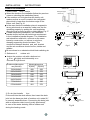
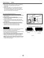
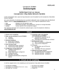
Before using your air conditioner, please read
this manual carefully and keep it for future reference.
SPLIT-TYPE
ROOMAIR CONDITIONER
Service Manual
Read This Manual
Please read this installation manual completely
before installing the product.
If the power cord is damaged, replacement work
shall be performed by authorised personnel only.
Installation work must be performed in accordance
with the national wiring Standards by authorised
personnel only.
Contact an authorised service technician for
repair, maintenance or installation of this unit.
CONTENTS
SAFETYPRECAUTIONS
Warning ........................................................................................................................................... 2
Caution ............................................................................................................................................ 2
INSTALLATION INSTRUCTIONS
Selecting installation place............................................................................................................. 3
Accessories ........ .......................................................................................................................... 4
Indoor unit installation..................................................................................................................... 5
Outdoor unit installation.................................................................................................................. 9
REFRIGERANT PIPE CONNECTION
Refrigerant pipe connection ........................................................................................................10
ELECTRICALWORK
Electrical work .................. ..........................................................................................................12
.
TEST RUNNING
Test running ...................... ...........................................................................................................13
! CAUTION
Contact an authorised service technician for repair or maintenance of this unit.
Contact an authorised installer for installation of this unit.
The air conditioner is not intended for use by young children or infirmed persons
without supervision.
Young children should be supervised to ensure that they do not play with the air
conditioner.
If the power cord is to be replaced, replacement work shall be performed by
authorised personnel only.
Installation work must be performed in accordance with the national wiring Standards
by authorised personnel only.
1
S
PRECAUTIONS
Read the follow SAFETYPRECAUTIONS carefully before installation.
Electrical work must be installed by a licensed electrician. Be sure to use the correct rating and
main circuit for the model to be installed.
Incorrect installation due to ignoring of the instruction will cause harm or damage, and the seriousness is classified by the following indications.
!
WARNING
This symbol indicates the possibility of death or serious injury.
!
CAUTION
This symbol indicates the possibility of injury or damage to property.
The items to be followed are classified by the symbols:
Symbol will background white denotes item that is PROHIBITED from doing.
! WARNING
1) Engage dealer or specialist for installation. If installation done by the user is defective, it will cause water
leakage, electrical shock fire.
2) Install according to this installation instructions strictly. If installation is defective, it will cause water
leakage, electrical shock fire.
3) Use the attached accessories parts and specified parts for installation. otherwise, it will cause the set to fall,
water leakage, electrical shock fire.
4) Install at a strong and firm location which is able to withstand the set ,s weight. If the strength is not enough
or installation is not properly done, the set will drop and cause injury.
5) For electrical work, follow the local national wiring standard, regulation and this installation instructions.
independent circuit and single outlet must be used. If electrical circuit capacity is not enough or defect found
in electrical work, it will cause electrical shock fire.
6) Use the specified cable and connect tightly and clamp the cable so that no external force will be acted on
the terminal. If connection or fixing is not perfect, it will cause heat-up or fire at the connection.
7) Wiring routing must be properly arranged so that control board cover is fixed properly. If control board cover
is not fixed perfectly, it will cause heat-up at connection point of terminal, fire or electrical shock.
8) When carrying out piping connection, take care not to let air substances other than the specified
refrigerant go into refrigeration cycle. Otherwise, it will cause lower capacity, abnormal high pressure
in the refrigeration cycle, explosion and injury.
9) Do not modify the length of the power supply cord or use of extension cord, and do not share the
single outlet with other electrical appliances. Otherwise, it will cause fire or electrical shock.
! CAUTION
1) This equipment must be earthed and installed with earth leakage current breaker. It may cause electrical
shock if grounding is not perfect.
2) Do not install the unit at place where leakage of flammable gas may occur. In case gas leaks and
accumulates at surrounding of the unit, it may cause fire.
3) Carry out drainage piping as mentioned in installation instructions. If drainage is not perfect, water
may enter the room and damage the furniture. AFETY
2
INSTALLATION INSTRUCTIONS
Selecting installation place
More than 15cm
Read completely, then follow step by step.
Indoor unit
Do not expose the indoor unit ot heat or steam.
More than 12cm
More than 12cm
Select a place where there are no obstacles
in front or around the unit.
Make sure that condensation drainage can
be conveniently routed away.
Do not install near a d oorway.
More than 2.3m
Ensure that the space on the left and right
Fig.1
of the units imore than 12cm.
Use a stud finderto locate studs to prevent unnecessary damage to the wall.
The indoor unit should be installed on the wall at a height of 2.3 metres or more from the floor.
Theindoor unit should be installedallowing a minimum clearance of 15cm from the ceiling.
Any variations in pipe length will/may require adjustment to refrigerant charge.
There should not be any direct sunlight. Otherwise,het sun will fade the plastic cabinet and
affect ts
i appearance. If unavoidable, sunlight prevention should be taken into consideration.
More than30cm
Outdoor unit
If an awning is built over the outdoor unit to
More than30cm
prevent direct sunlight or rain exposure,
make sure that heat radiation from the
condenser i s not r estricted.
Ensure that the clearance around the back
More than 60cm
of the unit is more than 30cm and left side is
more than 30cm .The front of the unit should
More than 200cm
have more than 200cm of clearance and the
connection side (right side) should have more
Fig.2
than 60cm of clearance.
Do not place animals and plants in the path of the air inlet or outlet.
Take the air conditioner weight into account and select a place where noise and vibration
will not be an issue.
Select a place so that the warm air and noise from the air conditioner do not disturb neighbors.
Rooftop installation:
If the outdoor unit is installed on a roof structure, be sure to level the unit.
Ensure the roof structure and anchoring method are adequate for the unit location.
Consult local codes regarding rooftop mounting.
If the outdoor unit is installed on roof structures or external walls, this may result in excessive
noise and vibration, and may also be classed as a non serviceable installation.
Tools needed for i nstallation:
Hexagonal wrench (4mm)
Gas-leak detector
Vacuum pump
Gauge manifold
Users manual
Thermometer
Multimeter
Pipe cutter
Measuring tape
Level gauge
Screwdriver
Electric drill,Hole core drill (90 mm)
Specified torque wrenches: 1.8kgf.m,
4.2kgf.m, 5.5kgf.m, 6.6kgf.m
(different depending on model No.)
Spanner ( half union)
3
INSTALLATION INSTR
UCTIONS
Accessories
1
Name ofAccessories
Installation Plate
2
ClipAnchor
5-8(depending on models)
3
Self-tapping Screw AST3.9X25
5-8(depending on models)
4
Seal(For cooling & heating models only)
1
5
Drain Joint(For cooling & heating models only)
1
6
Remote controller
1
7
Self-tapping Screw B ST2.9X10
8
Remote controller holder
9
Quick connecting refrigerant pipe
Number
Q ty
1
2
Optional
parts
1
1
Note:Except the above parts provided, the other parts needed during installation you must purchase.
Installation plate
1
CAUTION
3 Mounting screwA
2 Clip anchor
15
cm
abo
ve
or
Use a stud findert o locate studs to prevent
unnecessary damage to the wall.
A minimum pipe run of 3 metres is required
to minimise vibration & excessive noise.
Two of the A, B and C directions should be
free from obstructions.
This illustration is for explanation purposes
only.
Copper lines must be insulated independently.
mo
re
12cm a
bove
Air F
ilter
2.3m
A
Air Outlet
30c
ma
bov
e
or m
60cm above
12cm
ig.3
Quick connecting
refrigerant pipe
ore
e
bov
ma
30c
Remote Controller
B
e
bov
ma
c
200
60c
6
ma
bov
e
SETTEMPERATURE ( C)
FAN
HIGH
MED
LOW
AUTO
COOL
DRY
HEAT
MODE
SWING
ON/OFF FAN SPEED
SLEEP
RESETLOCK
AIR
DIRECTION
F
4
8
7
TEMP
C
Mounting screw B
ST2.9x10-C-H
TIMER ON
TIMER OFF
LED
DISPLAY TURBO
Remote controller
holder
INSTALLATION INSTR
UCTIONS
Indoor unit installation
Correct orientation
of I nstallation Plate
1. F it t he Installation Plate
1. Fit t he installation plate horizontally
on structural parts of t he wall with
spaces around the installation plate.
2. I f the wall i s made of brick, concrete or
the like, drill f ive or eight 5 mm diameter holes
in the wall. I nsert Clip anchor for appropriate
mounting screws.
3. Fit t he installation plate on the wall with five
or eight t ype “ A” s crews.
Fig.4
150mm or more to ceiling
Indoor unit outline
150
Installation plate
140
120mm or
more to wall
45
45
Left refrigerant
pipe hole 65
Right refrigerant
pipe hole 65
815
Model A
150mm or more to ceiling
Installation plate
Indoor unit outline
100
110
120mm or
more to the
wall
45
286
120mm or
more to the
wall
45
Fit t he Installation Plate and drill holes i n
the wall according to the wall s tructure
and corre sponding mounting points on
the installation plate.(Dimensions are
in “ mm” u nless otherwise stated)
NOTE: The installation dimensions
are slightly different according to
the different models. See Fig.5.
280
120mm or
more to wall
Note:
Rear-left pipe
hole 65mm
Rear-right pipe
hole 65mm
906
Model B
Above 150 from the ceiling
Hooked Part
1080
105
70
Above120mm
from the wall
330
Above120mm
from the wall
65
45
45
65
Indoor Unit Outline
Model C
Fig.5
2. Drill a h
ole in the wall
Wall ndoor
Outdoor
I
5-7mm
1. Determine hole positions according to
the diagram detailed in Fig.5. Drill
one (1) hole ( 90mm) slanting slightly
to outdoor side.
2.Always use wall hole conduit when
drilling metal grid, metal plate or t he like.
Fig.6
5
INSTALLATION
3. Dr aina ge Installa
INSTRUCTIONS
tion
Drainage
1. Run the drain hose sloping downward. Do not
install the drain hose as illustrated in Fig.7.
2. When connecting extension drain hose, insulate
the connecting part of extension drain hose with
a shield pipe, do not let the drain hose slack.
Do not form a rise
Fig.7
4. Connecting the r
Do not put the hose
end into water or any
container
efriger ant pipes
4.1 Tools needed
-Youwillrequirethefollowingtoolstocarryoutthis
installationworkcorrectly:
1xopen-endedspanner,19mm
1xopen-endedspanner,22mm/24mm
1xopen-endedspanner,24mm/27mm
1xAllenkey,5mm
1xPhilipsscrewdriver
1xleakdetectionsprayoralternativelysoapsuds
(water/detergent mix)
Refrigerant pipe
Connectors(both ends):
4.2 Important information
Followthedetailedinstructionsforconnecting
therefrigerantpipestothe indoor unit and
outdoor unit.Wecanonlyprovideawarrantyif
thelinesareinstalledcorrectlyasdescribedin
theinstructions.
Donotremovethesealingcapsandstoppers
untilimmediatelybeforeyouinstallthelines.
Topreventleaks,ensurethatthequick-release
screwconnectionsareabsolutelyfreeofdirt.
Moistureorforeignbodieswilladverselyaffect
thefunctionofthequick-releaseconnectors,
leadingtoariskofrefrigerantloss(notcovered
bythewarranty).
Onlyinstallrefrigerantlinesoutdoorsindry
weather.
Therefrigerantlinesmustnotbeinstalledand
thenplasteredover.
Pleasemakesurethatrefrigerantisnever
allowedtoentertheenvironment.
Improperhandlingofrefrigerantmaybeharmful
tohealth.Alwayswearworkglovesandgoggles
whenhandlingrefrigerant.
Donotsmokeduringtheinstallationwork.
Theequipmentmustneverbeoperatedwithout
therefrigerantlinesconnected,otherwisethe
equipmentwillbedamagedimmediately.
Thescrewconnectionsmayonlybetightened
usingtheappropriateopen-endedspanner.
Fig.8
NOTE: To distinguish the connectors
to be connected to the indoor unit and
outdoor unit, the connectors of the
refrigerant pipe has been labelled A ,
B , C and D . Ensure the
marks on the connectors are the same
to the indoor s and outdoor s respectively
during connection.
,
6
,
INSTALLATION
INSTRUCTIONS
Rememberthatiftheyaretightenedwithtoo
little torquetheywillleakbutiftheyaretightened
with toomuchtorque,thescrewconnectionsmay
sufferdamage.Ifyoushouldnotbeconfident
aboutconnectingtherefrigerantlineconnectors
yourself,itisimperativethatyoucontactyour
customerserviceteamorarefrigerationcontractor.
Important! TheEQvalvesareonlydesignedfor
one-timeinstallation.Theirsealcan notbe
guaranteediftheyareinstalledonmorethanone
occasion.Thiswillalsovoidthewarranty.
Fig.9
4.3 Connecting the refrigerant pipes to indoor
unit
1
2
1. Do not remove the plastic seals from the indoor
equipment and the appropriate refrigerant pipe
until immediately before you connect them.
2.Align the refrigerant pipes correctly, make sure
the dimensions of the connecting refrigerant pipe
are the same. Place the screw connector on the
refrigerant pipes just on to the thread on the
indoor equipment and tighten the first few threads
by hand. See Fig.9.
Fig.10
IMPORTANT: Before you continue, it is essential
that you read the following instructions carefully.
,,
3. Hold the points marked ,, 1 using
an open-ended
spanner and turn the nuts only at the points
marked ,, 2 ,,using an open-ended spanner
(Select the appropriate spanner according to the
dimensions of the connector). See Fig.10 & 11.
4. Ensure that the screw connectors do not skew as
you tighten them and work quickly.
IMPORTANT: Since the coupling works with tapping
rings, it may leak if you undo and reconnect the
pipes.This will also void the warranty.
Fig.11
5.After finishing the connection, use the tape to
wrap the refrigerant pipe and connecting cable
together. See Fig.12.
Fig.12
7
INSTALLATION
Note: Route the package of pipes/hoses in the
direction of (rear)right or (rear)left. See Fig.13 .
INSTRUCTIONS
Rear-right piping
5.Bundle the tubing, connecting cable with tape
securely, evenly as shown in Fig.14.
Because the condensed water from rear of the
indoor unit is gathered in ponding box and is
piped out of room. Do not put anything else in
the box.
CAUTION:
Do not allow the piping to let out from the back of
the indoor unit.
Be careful not to let the drain hose slack.
Heat insulated both of the auxiliary piping.
Besure that the drain hose is located at the
lowest side of the bundle. Locating at the upper
side can cause drain pan to overflow inside the
unit.
Never intercross nor intertwist the power wire
with any other wiring.
Run the drain hose sloped downward to drain
out the condensed water smoothly.
Rear-left piping
Fig.13
Indoor unit
Ponding box
Connective
cable
Pipe room
Connective
pipe
Wrapping belt
5. Indoor unit installa
Drain hose
tion
1. Feed the package of pipes/hoses through the hole
in the wall.
2. Hook the indoor unit onto the upper portion of the
installation plate.(Engage the two hooks of the rear
top of the indoor unit with the upper edge of the
installation plate.) Ensure that the hooks are
properly seated on the installation plate by moving
it left and right.
3.The female half can easily be made by lifting the
indoor unit with a cushioning material between the
indoor unit and the wall. Get it out after finish piping.
4. Press the lower left and right sides of the unit
against the installation plate until the hooks engage
into their slots.
Fig.14
Upper hooker
Low hooker
Cushioning
material
Fig.15
8
INSTALLATION
INSTRUCTIONS
Outdoor unit installation
Outdoor unit
1. Outdoor installa
tion pr ecaution
Select the location for installation(follow the previous
notes on selecting the installation place).
If the outdoor unit is higher thanthe indoor unit,
make sure that a curve is made in the refrigerant
pipe which is lower than the bottom edge of the
indoor unit. See Fig.16.
In the case that the installation place is exposed to
strong wind such as a seaside, make sure the fan
operating properly by putting the unit lengthwise
along the wall or using a dust or shield plates, Fig.17.
If need suspending installation, the installation
bracket should accord with technique requirement
in the installation bracket diagram. The installation
wall should be solid brick, concrete or the same
intensity construction, or actions to reinforce,
damping supporting should be taken. The
connection between bracket and wall, bracket
and the air conditioner should be firm, stable and
reliable.
Be sure there is no obstacle which block radiating air.
2. Settlement of
Refrigerant pipe
Indoor unit
Curve
ig.16
F
Strong
wind
Fig.17
outdoor unit
Anchor the outdoor unit with a bolt and nut
10 or 8 tightly and horizontally on a
concrete or rigid mount.
Mountingdimensions
B(mm)
700x540x240
458
250
685x430x260
460
276
780x540x250
549
276
760x590x285
530
290
845x700x320
560
335
775x545x310
600
320
670x540x265
481
276
3. Dr ain joint installa
W
D
A(mm)
B
Outdoorunitdimension
mm(WxHxD)
A
Fig.18
tion
Fit the seal into the drain elbow, then insert the drain
joint into the base pan hole of outdoor unit, rotate 90
to securely assemble them. Connecting the drain joint
with an extension drain hose (Locally purchased),
in case of the water draining off the outdoor unit
during the heating mode.
9
Seal
Drain joint
Base pan hole of
outdoor unit
Seal
Drain hose
Fig.19
REFRIGERANT
4. Connecting the r
PIPE CONNECTION
efriger ant pipe to outdoor unit
CAUTION: For your safety, always wear goggles
and work gloves when connecting the pipes.
NOTE: To distinguish the connectors to be connected
to the indoor unit and outdoor unit, the connectors
of the refrigerant pipe has been labelled A ,
B , C and D . Ensure the marks
on the ,
,
connector are the same to the indoor s and outdoor s
respectively during connection.
1. First remove the water tray on the outdoor unit
as shown in Fig.20.
2. Do not remove the plastic seals from the outdoor
unit and the appropriate refrigerant pipes until
immediately before you connect them, Fig.21.
3.Align the refrigerant pipes correctly so that they
line up with the valves and are not stressed.
Place the screw connector on the refrigerant line
just on to the thread on the outdoor unit and
tighten the first few threads by hand, Fig.22.
NOTE: The refrigerant pipes must be connected
to the valves on the outdoor unit with as little
stress as possible.
IMPORTANT: Before you continue,it is essential
that you read the following instructions carefully.
4. Now tighten the bottom screw connector first
and then the top screw connector using the
spanner. Hold the points marked
,open-ended
, ,
and turn the
1 using an open-ended spanner
,, ,,
nuts only at the points marked 2 , using an
open-ended spanner (Select the appropriate
spanner according to the dimensions of the
connector), see Fig.23.
Ensure that the screw connectors do not skew
as you tighten them and work quickly. See the
next page for the proper torque.
IMPORTANT: Since the coupling works with
tapping rings, it may leak if you undo and
reconnect the pipes.This will alsovoid the
warranty.
Fig.20
F
Fig.22
2
1
1
Fig.23
10
2 ig.21
REFRIGERANT
PIPE CONNECTION
Coupling size (last 2 part numbers)
Pound-force foot(1bf-ft)
Newton meter(N-m)
Kilogram-force meter(kgf-m)
-06(9.5mm dash size)
18 - 20
24.4 - 27.1
2.4 - 2.7
-08(12.7mm dash size)
30 - 35
40.6 - 47.4
4.1 - 4.8
-12(19.1mm dash size)
45 - 50
61.0 - 67.7
6.2 - 6.9
-16(25.4mm dash size)
60 - 65
81.3 - 88.1
8.2 - 8.9
Aftercompletingsteps1-4,checkthatallthe
connectionsaresealedcorrectlyusingleak
detectionsprayorsoapsuds.Ifanybubblesform,
thesystem hasaleakandthescrewconnectors
mustberetightenedusinganopen-endedspanner.
5.Nowremovethecoveronthetopvalveusinga
19mmopen-endedspanner.Openthevalveby
turningitcounter-clockwiseasfarasitwillgo
usinga5mmAllenkey.Thevalveisnowopen.If
thevalveisnotopenedfully,thesystemmay
malfunctionandsufferdamage.Screwthecover
backontothetopvalveandtightenitwellto
ensurethatitisproperlysealed. See Fig.24.
6.Nowremovethecoveronthebottomvalveusing
a19mmopen-endedspanner.Openthevalve by
turningitcounter-clockwiseasfarasitwillgo
usinga5mmAllenkey.Thevalveisnowopen.
Ifthevalve isnotopenedfully,thesystemmay
malfunctionandsufferdamage.Screwthecover
backontothebottom valveandtightenitwellto
ensurethatitisproperlysealed. See Fig.25.
Fig.24
Important! Theconicalringonthevalvehasan
importantsealingfunctiontogetherwiththesealing
seatinthecaps.Ensurethatyoudonotdamagethe
coneandthatyoukeepthecapfreeofdirtanddust.
7.Aftercompletingsteps1-6,checkthatallthe
connectionsaresealedcorrectlyusingleak
detectionsprayorsoapsuds.Ifanybubblesform,
thesystemhasaleakandthescrewconnectors
mustberetightenedusinganopen-endedspanner.
8.Starttheequipmentsothattheoperating
pressures buildupinsideit.Checkallthe
connectorsagainforsignsofleaks
a)duringcoolingmode
b)inheatingmode.
Ifanybubblesform,thesystemhasaleakandthe
screwconnectorsmustberetightenedusingan
open-endedspanner.
Fig.25
11
ELECTRICAL
Electrical w
ork
Electric safety regulations for the initial Installation
1. If there is serious safety problem about the power
supply, the technicians should refuse to install the air
conditioner and explain to the client until the problem
is solved.
2. Power voltage should be in the range of 90%~110%
of rated voltage.
3.The creepage protector and main power switch with a
1.5 times capacity of Max. Current of the unit should
be installed in power circuit.
4. Ensure the air conditioner is grounded well.
5.According to the attached Electrical Connection
Diagram located on the panel of the outdoor unit to
connect the wire.
6.All wiring must comply with local and national electrical
codes and be installed by qualified and skilled
electricians.
7. An individual branch circuit and single receptacle used
only for this air conditioner must be available. See the
following table for suggested wire sizes and fuse
specifications:
Appliance Amps
Cover
Screw
Fig.26
Frame
Panel
Electrical
box cover
AWG W ire S ize
10
18
13
16
18
14
25
12
30
10
Screw
Fig.27
Terminal block of indoor unit
NOTE:The cable size and the current of the fuse
or switch are determined by the maximum current
indicated on the nameplate which located on the
side panel of the unit. Please refer to the nameplate
before selecting the cable, fuse and switch.
Connect the ca
outdoor unit
WORK
ble betw een indoor unit and
NOTE:
Before performing any electrical work, turn
off the main power to the system.
1.The inside and outside connecting cable can be
connected without removing the front grille.
2. Connect cables according to their marks to
terminals.
3. Lift the indoor unit panel up, remove the electrical
box cover by loosening the screw.
12
TO OUTDOOR UNIT
ModelA
TO OUTDOOR UNIT
Model B
ELECTRICAL
WORK
4. Ensure the colour of wires of outdoor unit and the
,
terminal Nos. are the same to the indoor s
respectively.
5. Wrap those cables not connected with terminals
with insulation tapes, so that they will not touch
any electrical components. Secure the cable onto
the control board with the cord clamp.
Connectthecabletotheoutdoorunit
Outdoor unit
1. Remove the cover control from the unit by loosening
the 3 screws.
2. Dismount caps on the conduit panel.
3.Temporarily mount the conduit tubes(not included)
on the conduit panel.
4. Properly connect both the power supply and low
voltage lines to the corresponding terminals on the
terminal block.
5. Ground the unit in accordance with local codes.
6. Be sure to size each wire allowing several inches
longer than the required length for wiring.
7. Use lock nuts to secure the conduit tubes.
Terminal block
Ove
r 40
mm
G
Conduit panel
Connecting
cable
Power supply
cord
Cover control
Terminal block of outdoor unit
WARNING
Be sure to comply with local codes while running the
wire from the indoor unit to the outdoor unit.
Every wire must be connected firmly.
No wire should be allowed to touch refrigerant tubing,
the compressor or any moving parts.
Loose wiring may cause the terminal to overheat or
result in unit malfunction.Afire hazard may also exit.
Therefore, be sure all wiring is tightly connected.
Note :To prevent wires loosening or leaving the Cord
Clamp, please select proper cord diameter to fill the
holes on the cord clamp.
13
L1(L) L2(N) L1 L2 S
POWER SUPPLY
TO INDOOR UNIT
ModelA
POWER SUPPLY
TO INDOOR UNIT
Model B
Fig.28
TEST RUNNING
CAUTION
CAUTION
CAUTION
CAUTION
After the confirmation of the above conditions, prepare the wiring as follows:
1) Never fail to have an individual power circuit specifically for the air conditioner.As for
the method of wiring, be guided by the circuit diagram posted on the inside of control
cover.
2)The screw which fasten the wiring in the casing of electrical fittings are liable to come
loose from vibrations to which the unit is subjected during the course of
transportation. Check them and make sure that they are all tightly fastened. (If they
are loose, it could cause burn-out of the wires.)
3) Specification of power source.
4) Confirm that electrical capacity is sufficient.
5)See to that the starting voltage is maintained at more than 90 percent of the rated
voltage marked on the name plate.
6)Confirm that the cable thickness is as specified in the power source specification.
7)Always install an earth leakage circuit breaker in a wet or moist area.
8) The following would be caused by voltage drop.
Vibration of a magnetic switch, which will damage the contact point, fuse breaking, disturbance of the
normal function of the overload.
9) The means for disconnection from a power supply shall be incorporated in the fixed
wiring and have an air gap contact separation of at least 3mm in each active(phase)
conductors.
Test r unning
Perform test operation after completing gas leak check at the flare nut connections and
electrical safety check.
Check that all tubing and wiring have been properly connected.
Check that the gas and liquid side service valves are fully open.
1. Connect the power, press the ON/OFF button on the remote controller to turn the unit on.
2. Use the MODE button to select COOL, HEAT,AUTO and FAN to check if all the functions
works well.
3. When the amient temperature is too low(lower than 17 C), the unit cannot be controlled by
the remote controller to run at cooling mode, manual operation can be taken. Manual
operation is used only when the remote controller is disable or maintenance necessary.
Hold the panel sides and lift the panel up to an angle until it remains fixed
with a clicking sound.
Press the Manual control button to select theAUTO or COOL, the unit will
operate under ForcedAUTO or COOLmode(seeUser Manual for details).
4. The test operation should last about 30 minutes.
Manual
switch
Auto/cool o
14
2190 NW 89 Place - Doral, FL 33172 USA
Tel: (305)594-4972 Fax (305) 675-2212
www.klimaire.com
[email protected]
The design and specifications are subject to change without prior notice for product
improvement. Consult with the sales agency or manufacturer for details.