1
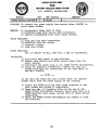
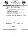
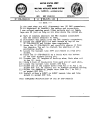
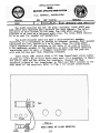
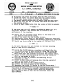
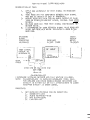
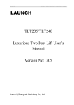
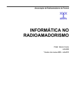
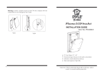
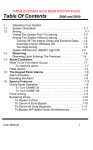
THE
R-390
COOKBOOK
BY A. CARMODY,
w 2LE/AAR2Q,R
The R—390 COOKBOOK was intended to be used in conjunction
with the R-390/URR Service Manual. However, sufficient
information is provided so that each modification can be
accomplished without the aid of the Service Manual.
These modifications have been incorporated into several
receivers with excellent results. The Author, however,
assumes no responsibility for the operation of these
circuits.
A. Carmody
September, 1983
(C) Copywrite, 1983, Empty Cloud, Canandaigua, N.Y.
All rights reserved
CONTENTS
I TEM
PAGE
POWER SUPPLY SUB-CHASSIS MODIFICATION
1-2
IF SUB-CHASSIS MODIFICATION
3-Li.
AF SUB-CHASSIS MODIFICATION
LOW IMPEDANCE SPEAKER CONNECTION
7
ANTENNA IN PUT CONVERSION TO ~O OHMS
8-9
UNITED STATES ARMY
MARS
MILITARY AFFILIATE RADIO SYSTEM
A.J. CARMODY, AAR2Q.R/W2LE
MODULE
POWER SUPPLY SUB-OHS
REV
A
~
REF PAGE ( S)
1
REMARKS
‘9 ~, 96
PURPOSE: To convert the power supply from vacuum tubes (26Z~W) to
solid state diodes.
REASON:
1) Replacement tubes hard to find.
2) Eliminate heat from vacuum tube rectifiers.
3) Improve reliability with solid state diodes.
TOOLS REQUIRED:
1) Long phillips head screwdriver
2) Soldering iron and solder
3) Diagonal cutters
L~) Long nose pliers
PARTS REQUIRED:
Two (2) 1NLi.007 diodes, 1000 PIV, 1 amp or equivalent.
PROCEDURE:
1) Disconnect main power to the receiver.
2) Remove tube shields and 26Z54 vacuum tubes from the
power supply.
3) Disconnect the power plug to the POWER SUPPLY SUB-CHASSIS.
L~) Using the phillips screwdriver, remove the four (L1.)
screws that hold the transformer to the side panel of
the MAIN CHASSIS.
NOTE
In the next two steps you will loosen three (3) captive
screws which hold the power supply to the chassis.
~) Locate
6)
7)
the GREEN phillips head screw adjacent to the
tube socket and loosen it completely.
There are two (2) locating holes in the top of the
POWER SUPPLY SUB-CHASSIS bracket. Below each hole is a
GREEN phillips head screws Loosen both of these screws
completely.
Grasp the POWER SUPPLY SUB~CHASSIS and remove it from
the receiver.
(1)
UNITED STATES ARMY
MARS
MILITARY AFFILIATE RADIO SYSTEM
A.J.
MODULE
~POWER~BUPPLY ~SUB-CHS
T
REV
A
CARMODY, AAR2~R/W2LE
1
REF PAGE (S)
9~, 96
REMARKS
I,
8) Place the POWER SUPPLY SUB—CHASSIS on a bench with the
bottom of the tube sockets facing you.
NOTE:
When installing
their polarity.
diodes, it is important
See Fig. 1.
to observe
9) Install a diode on socket XV80]., the cathode lead
(banded end) soldered to Pin 3.
10) Solder the anode lead to XV8O1 Pin 6.
11) Install a diode on socket XV802, the cathode lead
(banded end) soldered to Pin 3.
12) Solder the anode lead to XV802 Pin 6.
THIS COMPLETES MODIFICATION OF THE POWER SUPPLY SUB-CHASSIS
ANODE LEAD
EI~T~1ODE
FIG. I
(2)
LEAD
UNITED STATES ARMY
MARS
MILITARY AFFILIATE RADIO SYSTEM
A.J. CARMODY, AAR2QR/W2LE
MODULE
IF SUB-CHASSIS
REV
A
REF PAGES
199,128,129
REMARKS
1
-
PURPOSE: To replace ballast tube 3TF7 with a conventional vacuum tube.
REASON:
1) Ballast tubes are hard to find and expensive.
2) Other methods using power dropping resistors dissipate
excessive beat under the chassis which is undesirable.
3) Use of voltage regulators require more parts and are
more costly.
Li.) This method allows easy substitution of ballast tubes....
if you are lucky enough to find them.
TOOLS REQUIRED:
Wire strippers
Set of Allen wrenches
Phillips head screwdriver
Soldering iron and solder
Assortment of multi-colored fiber-tipped marking pens.
PARTS REQUIRED:
Three (3) inches #22 AWG PVC insulated hook-up wire
One (1) 1 2BH7 or 1 2BY7 vacuum tube
PROCEDURE:
1) Disconnect main power to the receiver.
NOTE
In the following step
the IF SUB-CHASSIS to
loosening the shafts,
of the BANDWIDTH knob
2) Using an Allen
Oldham coupler
panel controls
3) Disconnect the
--
-
you will loosen two (2) shafts from
the controls on the front panel. Before
it is important to note the position
and the BFO PITCH knob.
wrench, loosen the set screw on each
which secures each shaft from the front
to the IF SUB—CHASSIS.
power plug to the IF SUB—CHASSIS.
(3)
UNITED STATES ARMY
MARS
MILITARY AFFILIATE RADIO SYSTEM
A.J. CARMODY, AAR2QR/W2LE
MODULE
IF SUB—CHASSIS
1
REV
A
1
REF PAGE (5)
99,128, 129
REMARKS
~
-
NOTE
In the next step you will disconnect two (2) BNC connectors.
It is important to identify the cables and connectors.
I use colored marking pens. Other methods such as tages,
tape are OK just as long as you know where the cables go.
Ii.) Mark or somehow identify the BNC chassis connectors
and the cables attached to them.
~) Disconnect the cables from the BNC chassis connectors.
6) Locate the GREEN phillips head screws on top of the
IF SUB—CHASSIS and loosen them completely.
7) Grasp the IF SUB-CHASSIS and carefully remove it from
the chassis. Try not to disturb the position of the
protruding shafts.
8) Locate the ballast tube 3TF7 and remove it from it’s
socket.
9) Place the IF SUB—CHASSIS on a bench with the bottom
of the tube sockets facing you.
10) Prepare two (2) lengths of hook-up wire. Each wire cut
to one (1) inch.
11) Strip ¼ inch of insulation from each end of each wire.
12) Locate the ballast tube socket XRT ~l2.
13) Solder one of the jumper wires from Pin 2 to Pin L. on
socket XRT ~l2. Be careful not to disturb existing wiring.
lLi.) Solder the remaining jumper wire from Pin 7 to Pin ~
on socket XRT S12.
1~) Install either a 12BY7 or 125117 vacuum tube and tube
shield in socket XRT ~l2,
THIS COMPLETES MODIFICATION OF THE IF SUB-CHASSIS
(1$.)
UNITED STATES ARMY
MARS
MILITARY AFFILIATE RADIO SYSTEM
A • J • CARMODY, AAR2Q.R/W2LE
MODULE
AF SUB-CHASSIS
REV
I
REF PAGE (S)
197,98.99.131
A
REMARKS
1
-
PURPOSE: To replace the 6082 (2L~. volt f 11) regulator tubes which are
expensive and hard to find with 6o8o (6 volt f 1].) tubes.
NOTE: 6AS7G tubes are electrically
similiar to the 6o8o
but are too large to fit Into the R-390.
TOOLS REQUIRED:
Phillips head screwdriver
Soldering iron and solder
Wire strippers
Diagonal cutters
Nut driver set or small socket set
PARTS REQUIRED:
Power diode, stud mounted with mounting hardware
lNll83, 3~amp, ~0 Ply or equivalent.
Three feet #20 AWG or larger PVC insulated hook—up wire,
Thermal heat sink compound — available at Radio Shack stores.
---NOTE--The original filament circuit of the two (2) regulator tubes
V6O~and V6o6 is wired in parallel.
In this modification,
the
filament circuit will be connected in series as indicated in
Fig, 1.
Polarity of the diode doesn’t matter. Just be sure the mounting stud is securily fastened to the sub—chassis for
heat-sinking purposes,
PROCEDURE:
1) Disconnect main power to the receiver.
2) Locate the two regulator t~.ibes V6O~and v6o6 on the
AF sub—chassis,
3) Remove the holding rings and the regulator tubes from
their sockets,
Li.) Disconnect the two (2) power plugs from the AF sub-chassis.
~) Locate the GREEN phillips head captive screws. Loosen them
completely.
6) Grasp the AF sub-chassis, gently removing the unit from.
the chassis.
24VAC
V605
V606
8f”~7
7 t’,~
rI~,.
(S)
UNITED STATES ARMY
MARS
MILITARY AFFILIATE RADIO SYSTEM
A,J. CARMODY, AAR2Q,R/W2LE
MODULE
AF SUB-CHASSIS
REV
A
J
REF PAGE (5)
97,98,99,131
1
REMARKS
-
7) Set the AF subohassis on a bench with the bottom of the
tube sockets facing you.
NOTE: There are several large holes in the chassis around
the base of the octal tube sockets to provide air
circulation. We will use one of these holes to mount
the stud diode.
8)
Mount the stud diode in one of the chassis holes. Select
a hole between the octal tube sockets, If the hole is
larger than the stud, use flat washers from your junk box.
Be sure to coat the flat base of the stud diode with
heat-sink compound. Also apply a thin coat of compound to
the flat washers,
9) Wire the circuit, ref ering to Fig. 2A and 25.
V606
V605
ORIGINAL
FIG2A
V606
\
V605
MODIFIED
\BLK
FIG2B
(6)
\
\BLK
unsaw ae~,~a
~
MARS
MIUTARY AFFILIATE RADIO SYSTEM
A.J. CARMODY, AAR2QR/W2LE
MODULE
NONE
REV
I
-
--
REF PAGE (S)
1.2O.81.82,8~
1
REMARKS
LOW IMPEDANCE SPKR CONNECTI~Q~N
The R-390 receiver has two (2) audio channels, LOCAL AUDIO and
LINE AUDIO with seperate gain controls for each channel. The output
impedance of each channel is 600 ohms. The LINE AUDIO channel is
intended to be used as a balanced audio line. The LOCAL AUDIO channel
is to be used for speaker and headphones.
The R-390 receiver does not have a self-contained speaker.
Therefore, it Is necessary to provide an external speaker. Most speaker
impedances are low, typically 14. to 16 ohms. Since the LOCAL AUDIO
output ix~edance of the receiver is ~OO ohms, if we wish to connect
a low impedance speaker to the receiver, an audio impedance matching
transformer must be used. A filament transformer from the junk box
will work but has poor high frequency response.
Radio Shack (TM) stores offer a 70V Line Transformer stock number
32-1031 for under $~.OOwhich works very well. It’s secondary is tapped
for 14.18/16 ohms and has solder lug terminals. Connect the high
impedance primary of the transformer to TB2—6 and TB2-7 located on the
rear panel of the receiver. Refer to Fig. 1 for proper connections.
Di~Il~1)
REAR PANEL OF R-390 RECEIVER
SPKR
XFMR
(7)
WUIW
~IAl~~
A~I
MARS
MIUTARY AFFILIATE RADIO SYSTEM
A • J • CARMODY, AAR 2QR/W 2LE
MODULE
REV
REF PAGE (S)
I
REMARKS
I
NONE
I20,.i.7ati.8
INPUT connectors
CONV TO 50 OHMS
PURPOSE:
To replace antenna
input connectors ANTENNA
with S0-239
that mate with standard ham equipment.
Change antenna input from a balanced line to an unbalanced line.
REASON:
Adapters or “C” type connectors are difficult to locate and
are non-standard ham equipment.
Most ham stations use ~0 ohm unbalanced
coaxial
line.
TOOLS REQUIRED:
1) Phillips head screwdriver
2) Colored marking pens
3) Soldering iron arid solder
Li.) Long nose pliers
~) Wire strippers
6) #6—32 tap
PARTS REQUIRED:
1) Two (2) 50—239 coax sockets
2) Eight (8) #6-32 pan head screws
3) One (1) foot of hook-up wire
PROCEDURE:
1) Disconnect main power to the receiver
2) Place the receiver on a bench with the top removed and
the rear panel facing you.
NOTE
In the .next step you will remove the module containing the
antenna connectors, It is important to clearly mark the BNC
connectors J109, Jib, Jlll with tape or colored marking pens
before removing the cables from the module.
3)
Li.)
Locate the three (3) BNC connectors Jb09, JllO and Jlll
on the module,
Using a different color pen or tape, mark each BNC connector
and it’s associated cable.
(8)
W~SIW~$AI~
MARS
MIUTARY AFFILIATE RADIO SYSTEM
A,J. CARMODY, AAR2~R/W2LE
MODULE
-
NONE
-
REV
I
-
-
~) Disconnect the
REF PAGE(5)
1
I.2b.b. 7.ti.8
three (3) cables
REMARKS
ANTENNA INPUT CONV TO 50 OHMS
from the BNC connectors.
6) Locate the three (3) screws that hold the antenna module
to the rear panel. Remove and save the screws,
remove from the rear panel.
6) Remove and save the two (2) screws that hold the cover on
7) The module should now be free to
the antenna module,
9) Solder a small jumper wire from the center of JilO to ground.
NOTE
In the next step you will remove the BREAK-IN RELAY and it’s
associated hardware, This feature has no effect on the
performance of the receiver.
10) Remove the two insulated wires going to the relay coil
and tape the ends of the wires,
11) Remove the relay from the antenna module.
12) Unsolder all wires going to the antenna connectors 3107,3108.
13) Using a screwdriver, remove both antenna connectors Jb07,J108.
‘J~.) Remove ~ny wires ~ing
to the center of 3109 and Jill.
NOTE
In the next step you will put threads in the four mounting
holes of each SO-239 connectors,
l~) Locate the S0-239 antenna connectors and thread the four
(14.) mounting holes of each connector using the #6-32 tap.
16) Install one of the S0—239 connectors at J107 (UNBALANCED
WHIP) such that the connector is inside the antenna module,
17) Solder a small piece of hook—up wire from the center of
J107 to the center of Jl09,
18) Similiar to STEP 16, install the remaining SO—239
connector at 3108,
19) Solder a small piece of hook-up wire from the center of
Jio8 to the center of Jill.
20) Replace the cover on the antenna module.
21) Install the antenna module in the receiver.
22) Reconnect the three (3) cables to the BNC connectors,
I’ve found it ó~iivenient to connect a second receiver’s
antenna input to 3107 using a short cable and connect my
main antenna to 3108 so that the two receivers share the
same antenna.
(9)
TESTING R—390(
)/uRR RECEIVERS
DESCRIPTION OF TEST:
1.
APPLY ONE MICROVOLT CV) TEST SIGNAL TO RECEIVER
INPUT.
2. TUNE RECEIVER FOR ZERO—BEAT BETWEEN TEST SIGNAL
AND SF0 AT CENTER OF 2KC IF BANDPASS.
3. ADJUST RECEIVER GAIN FOR AN AUDIO OUTPUT OF PLUS
10DB OR OTHER CONVENIENT LEVER, (SIGNAL PLUS RCVR
NOISE).
~-I. DE—TUNE RECEIVEE~FROM TEST SIGNAL AND MEASURE RECEIVER NOISE.
5. A DIFFERENCE OF 20DB BETWEEN SIGNAL PLUS RECEIVER
NOISE AND RECEIVER NOISE INDICATES A GOOD R—390
RECEIVER.
-
STANDARD
SIGNAL
C-ENERATOR
AN/URM—25
RECE I.VER
R-390( )/uRR
TEST SIGNAL
OUTPUT 10
MICROVOLTS
LOCAL
AUDIO
OUTPUT
MET ER
TS-5~5/U
F
Ltc~uL~
~330OHM
COAX
CA BL E
Z=50 OHM
56 ~2 ~Z=7O
OHM
~M OH~:
CU—~40~/URM—25F
IMPEDANCE MATCHING NETWORD AND 10:1 VOLTAGE DIVIDER)
NOTE: CU—~0~/URM—25FIS SUPPLIED W/URM—25F MODEL ONLY.
FOR URM-25D AND OTHER MODELS CHANGE RESISTORS AND
CIRCUIT IN EITHER 5;1 OR 10:1 ATTENTUATORS TO AGREE
w/Cu—1+o~ CIRCUiT AS SHOWN ABOVE.
PROCEDURE:
1.
SET
A.
B.
C.
•D.
RECEiVER CONTROLS FORCW RECEPTION:
BANDWIDTH——2KC
AUDIO RESPONSE-—WIDE
BFO PITCH——ZERO
LIMiTER--OFF
T~7
2.
3.
k.
5.
6.
7.
E. FUNCTION-—MGC
F. RF GAIN——MAX
TUNE RECEIVER TO ZERO BEAT WITH TEST SIGNAL.
TURN BFO PITCH TO MINUS 1 OR PLUS 1.
PEAK ANTENNA TRIMMER FOR MAXIMUM INDICATION ON
TS-5~5.
Dc~ ________________
ADJUST RF GAIN FOR PLUS ~
DE—TUNE RECEIVER AT LEAST 1OKC FROM TEST SIGNAL
FREQUENCY.
TS—5~5NOW INDiCATES RECEIVER NOISE OUTPUT RESULTING
FROM STANDARD GAIN SETTING ESTABLISHED BY STEP FIVE
ABOVE. RECEIVER PASSES TEST IF NOISE iNDICATION ON
TS—5~5 IS M.!NUS 10DB CR LESS.
TEST FREQUENCIES:
1.5MC; (1—2 MC BAND)
3.OMC; ..(2_1~.MC BAND)
14—~
IviC BAND)
6.oMC,~((~—i6
12.OMC,
MC BAND)
2~-i..OMC, (16-32 MC BAND)
2
p~7