1
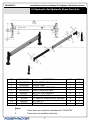
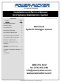
An Actuant Company
Installation and Service Manual
On-Highway Stabilization System
CONTENTS
Section
Part # 3010003373, REV 0E
Page
1.0 Receiving Instructions
2
2.0 Safety Issues
2
3.0 Hydraulic Fluid
4
4.0 Operating Parameters
4
5.0 Hydraulic Out/Down Parts
5
6.0 Hydraulic Out/Down Installation
6
7.0 Hydraulic Out/Down Operation
8
8.0 Manual Out/Down Parts
9
9.0 Manual Out/Hydraulic Down
Installation
10
10.0 Manual Out/Hydraulic Down
Operation
12
Work Truck
Hydraulic Outrigger Systems
11.0 Notes on Installation of Hydraulic 13
System
12.0 Warranty
14
(800) 745- 4142
Fax: (574) 256-1248
[email protected]
www.powerpackerus.com
© Copyright 2014, Power-Packer. All rights reserved.
3010003373
Installation and Service Manual On-Highway Stabilization System
1.0 Important Receiving Instructions
Visually inspect all components for shipping damage prior to
installation. Shipping damage is not covered by warranty. If shipping
damage is found, notify carrier at once. The carrier is responsible for
all repair and replacement costs resulting in damage from shipment.
For most current manual, see http://www.powerpackerus.com
Product descriptions and specifications are subject to change. For
specific versions related to your product, contact us.
2.0 Safety Issues
SAFETY FIRST
Read all instructions, warnings and cautions carefully. Follow all
safety precautions to avoid personal injury or property damage during
system operation. Power-Packer cannot be responsible for damage
or injury resulting from unsafe product use, lack of maintenance or
incorrect product and/or system operation. Do not remove warning
labels, tags or decals. Contact Power-Packer when in doubt as to the
safety precautions and operations.
This manual follows a system of safety alert symbols, signal words
and safety messages to warn the user of specific hazards. Failure to
comply with these warnings could result in serious personal injury or
death, as well as damage to equipment or other property.
This is a Safety Alert Symbol that appears throughout this manual. It
is used to alert you to potential physical injury hazards. Pay close
attention to Safety Alert Symbols and obey all safety messages that
follow this symbol to avoid possible serious personal injury or death.
Safety Alert Symbols are used in conjunction with certain Signal
Words that call attention to safety messages or property damage
messages and designate a degree or level of hazard seriousness.
The Signal Words used in this manual are WARNING, CAUTION,
and NOTICE.
WARNING indicates a hazardous situation that, if not avoided, could
result in death or serious injury.
CAUTION
CAUTION indicates a hazardous situation that, if not avoided, could
result in minor or moderate injury.
NOTICE
NOTICE indicates information considered important, but not hazardrelated (e.g. messages related to property damage.)
2
3010003373
Installation and Service Manual On-Highway Stabilization System
2.1 Safety Precautions
Failure to observe and comply with the following precautions could
result in death or serious personal injury, as well as property damage.
• Keep hands and feet away from hydraulic legs during
operation.
• Do not handle pressurized hoses.
Escaping oil under
pressure can penetrate the skin. If oil is injected under the
skin, see a doctor immediately.
• Do not exceed equipment ratings. Never attempt to lift a load
weighing more than the capacity of the system. Overloading
can cause equipment failure.
• Never set relief valve to a higher pressure than specified.
Higher settings may result in equipment failure.
• Be sure setup is stable before lifting load. Hydraulic legs
should be placed on a flat surface that can support the load.
Do not bridge. Where applicable, use support pads for added
stability. Do not weld or otherwise modify the hydraulic leg to
attach a base or other support.
• Immediately replace worn and damaged parts.
warranty, use only Power-Packer parts.
CAUTION
To protect
Failure to observe and comply with the following precautions could
result in minor or moderate personal injury, as well as property
damage.
• Avoid damaging hydraulic hose. Avoid sharp bends and
kinks when routing hydraulic hoses. Using a bent or kinked
hose will cause severe back pressure. Sharp bends and
kinks will internally damage the hose leading to premature
hose failure.
• Do not drop heavy objects on hose. A sharp impact may
cause internal damage to hose wire strands. Applying
pressure to damaged hose may cause it to rupture.
• Keep hydraulic equipment away from flames and heat.
Excessive heat will soften packings and seals, resulting in
fluid leaks. Heat also weakens hose materials and packings.
Protect hoses and hydraulic legs from weld spatter.
NOTICE
Hydraulic equipment must only be serviced by a qualified hydraulic
technician.
Specific safety messages appear throughout this manual in the left
hand column.
3
3010003373
Installation and Service Manual On-Highway Stabilization System
3.0 Hydraulic Fluid Specifications
NOTICE
Mixtures of hydraulic fluid
and fuel oil can cause seal
damage
resulting
in
subsequent
sticking
or
sluggish action of the
system
(and
voids
warranty). Damaged seals
must be replaced.
RECOMMENDED HYDRAULIC FLUIDS FOR POWER-PACKER
Power-Packer recommends using a quality ISO 32 Anti-wear hydraulic
fluid for most applications. If operating in cold temperatures (below
freezing) slow operation will occur. If slower operation in cold weather
affects your operations, we recommend using a fluid speciallyformulated for cold temperatures. We have found that ISO 15 High
Viscosity Index Anti-wear hydraulic fluids work well with Power-Packer
systems to -20° F. Some examples of these are:
•
•
•
Mobil DTE 10 Excel 15
Chevron Rando HDZ 15
Kendall Hyken Glacial Blu
If consistently operating at temperatures below -20°F, then we
recommend hydraulic fluids conforming to MIL-PRF-5606H or MIL-H5606A (obsolete). If you have any questions regarding fluid
recommendations, please call us.
4.0 Stabilization System Operating Parameters
Stabilization legs must be operated within design parameters. Design
parameters may vary from leg to leg and must be followed to ensure
expected behavior and a safe operating environment. Leg parameters
are documented on each part number specific drawing.
Stabilization systems must
be installed and operated
within the design
parameters of the crane and
vehicle
that
they are
intended to stabilize. Failure
to do so could result in
death or serious personal
injury, as well as property
damage.
4
3010003373
Installation and Service Manual On-Highway Stabilization System
5.0 Hydraulic Out/Hydraulic Down Parts List
ITEM
1
2
3
4
5.1
5.2
5.3
5.4
5.5
PART NUMBER
9010000783
1010002893
1010002896
1010002634
DN12367
15-1130
16-1030
DN10832
532037
Notes:
1.
2.
DESCRIPTION
STABILIZATION LEG
CENTER TUBE
EXTEND STABILIZER ARM
FIXED STABILIZER ARM
BOLT 1/2-13 X 4 GRADE 5
SCREW , 1/2-13 X 5.0
1/2" HELICAL SPRING LOCK WASHER
NUT, HEX 1/2
WEAR PAD
QTY
2
1
1
1
6
2
8
8
6
These items are contained in hardware kit 1010002738.
These items are available individually
5
NOTES
2
1
1
1
1
1
3010003373
Installation and Service Manual On-Highway Stabilization System
6.0 Hydraulic Out /Hydraulic Down Installation
Instructions
Stabilizer components are
heavy. To avoid possible
death or serious personal
injury, always follow safe
rigging and lifting practices.
The stabilization system includes a center tube, an extend stabilizer
arm with integral hydraulic extend cylinder, a fixed stabilizer arm,
two stabilizing legs, and mounting hardware (see assembly parts
list).
1. Center Tube Installation. Mount the center tube to the vehicle
so that it is supported at the truck frame. Additional support at
both ends of the tube as shown in figure 1 is recommended if
possible. The tube can be welded or mechanically fastened to
the supports. Welding of the tube to the supports is to be done
by a certified welder. Proper mounting of the tube is the
responsibility of the vehicle manufacturer. Consult Power-Packer
for assistance
Be sure to orient the center tube (item 2) so the reinforcing
weldments are up and the extend side is on the passenger side
of the vehicle (same side as the crane). Also, make sure there is
access to the extend cylinder ports. See figure 2. Install three
wear pads (item 5.5) in the extend side of the center tube as
shown in figure 2.
Figure 1
6
6
3010003373
Installation and Service Manual On-Highway Stabilization System
2. Stabilizer Arm Installation. The up and down orientation of the
bracket on the end of the stabilizer arms (item 3 and 4) can be used
to increase the range of mounting height for the stabilizer legs (item
1). The stabilizer legs must be positioned to reach the ground before
reaching their maximum stroke of 20 inches. Once the extend
stabilizer arm is oriented, install three wear pads (item 5.5) as shown
in figure 2. Insert the extend stabilizer arm (item 3) into the center
tube. Insert the fixed stabilizer arm (item 4) into the center tube.
Secure each stabilizer arm using 5” long ½” bolts (item 5.2), lock
washers (item 5.3), and nuts (item 5.4) provided (one per arm).
Torque nuts to 57-64 ft-lbs.
3. Stabilizing Leg Installation Mount the stabilizer legs (item 1) to the
mounting brackets using 4” long ½ inch class 5 bolts (item 5.1), lock
washers (item 5.3) and nuts (item 5.4) provided (three per leg).
Torque nuts to 57-64 ft-lbs.
Figure 2
Reinforcing Weldments
Extend Cylinder Port Access
7
3010003373
Installation and Service Manual On-Highway Stabilization System
7.0 Hydraulic Out/Hydraulic Down Operation
Instructions
1. Locate the truck on level ground. Set the truck parking brake
and (if necessary) place wheel chocks/blocks under the front
wheels before operating the stabilizers.
Operators and bystanders
must be clear of the stabilizing
legs during operation. Moving
stabilizers can cause serious
personal injury.
Stabilizing legs must be on
firm, level ground that will not
yield under load. If the ground
is soft or uneven, use stabilizer
pads to increase the bearing
area. Failure to do so may
allow the vehicle to tip over,
which could result in death or
serious personal injury.
2. Hydraulically extend the passenger side stabilizer arm. To
insure maximum vehicle stability, be sure to fully extend the
passenger side stabilizer arm before lowering the stabilizing
legs.
3. Hydraulically lower the stabilizing legs until they make solid
contact with the ground. Do not lift the truck. Stabilizers
increase vehicle stability only if the wheels remain firmly on
the ground.
4. To store the legs, hydraulically raise them until they are fully
retracted. Then hydraulically retract the passenger side
stabilizer arm.
Do not move the passenger side stabilizer arm in or out
with the legs extended. Damage to the system may
occur.
Do not move the truck with the stabilizer arm or the legs
extended. Property damage or personal injury may
occur.
During crane operation, the
tire on the opposite side of the
lifting load should not leave
the ground. If this occurs the
vehicle could tip over, which
could result in death or
serious personal injury. If the
load is within the rating of the
crane’s load radius chart,
relocate the truck closer to the
load.
8
3010003373
Installation and Service Manual On-Highway Stabilization System
8.0 Manual Out/Manual Down Parts List
Figure 3
ITEM
1
2
3
4
5.1
5.2
5.3
5.4
5.5
5.6
PART NUMBER
9010000783
1010002893
1010002894
1010002634
DN12367
15-1130
16-1030
DN10832
532037
2010000507
Notes:
1.
2.
DESCRIPTION
STABILIZATION LEG
CENTER TUBE
EXTEND STABILIZER ARM
FIXED STABILIZER ARM
BOLT 1/2-13 X 4 GRADE 5
SCREW , 1/2-13 X 5
1/2" HELICAL SPRING LOCK WASHER
NUT, HEX 1/2
WEAR PAD
INDEXING PLUNGER
QTY
2
1
1
1
6
1
7
7
6
1
These items are contained in hardware kit 1010002738.
These items are available individually.
9
NOTES
2
1
1
1
1
1
1
3010003373
Installation and Service Manual On-Highway Stabilization System
9.0 Manual Out/Hydraulic Down Installation
Instructions
Stabilizer components are
heavy. To avoid possible
death or serious personal
injury, always follow safe
rigging and lifting practices.
The stabilization system includes a center tube, an extend stabilizer
arm, a fixed stabilizer arm, two stabilizing legs, and mounting
hardware (see assembly parts list).
1. Center Tube Installation. Mount the center tube to the vehicle
so that it is supported at the truck frame. Additional support at
both ends of the tube as shown in figure 3 is recommended if
possible. The tube can be welded or mechanically fastened to
the supports. Welding of the tube to the supports is to be done
by a certified welder. Proper mounting of the tube is the
responsibility of the vehicle manufacturer. Consult PowerPacker for assistance.
Be sure to orient the center tube (item 1) so the reinforcing
weldments are up and the extend side is on the passenger side
of the vehicle (same side as the crane). Install three wear pads
(item 5.5) in the extend side of the center tube as shown in
figure 4.
Figure 3
10
3010003373
Installation and Service Manual On-Highway Stabilization System
2. Stabilizer Arm Installation. The up and down orientation of
the bracket on the end of the stabilizer arms (item 3 and 4) can
be used to increase the range of mounting height for the
stabilizer legs (item 1). The stabilizer legs must be positioned to
reach the ground before reaching their maximum stroke of 20
inches. Once the extend stabilizer arm is oriented, install three
wear pads (item 5.5) as shown in figure 4. Insert the extend
stabilizer arm (item 3) into the center tube. Secure the extend
stabilizer arm using the indexing plunger (item 5.6)
provided. Insert the fixed stabilizer arm (item 4) into the center
tube. Secure the fixed stabilizer arm using 5” long ½” bolts
(item 5.2), lock washers (Item 5.3), and nuts (item 5.4)
provided. Torque nuts to 57-64 ft-lbs.
3. Stabilizing Leg Installation. Mount the stabilizer legs (item 1)
to the mounting brackets using 4” long ½ inch class 5 bolts
(item 5.1), lock washers (item 5.3), and nuts (item 5.4) provided
(three per leg). Torque nuts to 57-64 ft-lbs.
Figure 4
11
3010003373
Installation and Service Manual On-Highway Stabilization System
10.0 Manual Out/Hydraulic Down Operation
Instructions
1. Locate the truck on level ground. Set the truck parking
brake and place (if necessary) place wheel
chocks/blocks under the front wheels before operating
the stabilizers.
Operators and bystanders
must be clear of the stabilizing
legs during operation. Moving
stabilizers can cause serious
personal injury.
Stabilizing legs must be on
firm, level ground that will not
yield under load. If the ground
is soft or uneven, use stabilizer
pads to increase the bearing
area. Failure to do so may
allow the vehicle to tip over,
which could result in death or
serious personal injury.
2. Disengage the indexing plunger. Manually extend the
passenger side stabilizer arm to full extension and
secure using the indexing plunger. To insure
maximum vehicle stability, be sure to fully extend the
passenger side stabilizer arm before lowering the
stabilizing legs.
3. Hydraulically lower the stabilizing legs until they make
solid contact with the ground. Do not lift the truck.
Stabilizers increase vehicle stability only if the wheels
remain firmly on the ground.
4. To store the legs, hydraulically raise them until they
are fully retracted. Then manually retract the
passenger side stabilizer arm and secure using the
indexing plunger.
Do not move the passenger side stabilizer
arm in or out with the legs extended.
Damage to the system may occur.
Do not move the truck with the stabilizer
arm or the legs extended. Property
damage or personal injury may occur.
During crane operation, the
tire on the opposite side of the
lifting load should not leave the
ground. If this occurs the
vehicle could tip over, which
could result in death or serious
personal injury. If the load is
within the rating of the crane’s
load radius chart, relocate the
truck closer to the load.
12
3010003373
Installation and Service Manual On-Highway Stabilization System
11.0 Notes on Installation of Hydraulic System
See figure 5 for identification of pump manifold ports for hose routing.
CR (Curb Rear) – hose to extend port of passenger side stabilization
leg that extends out
RR (Road Rear) – hose to extend port of driver side stabilization leg
that is fixed
CF or RF – hose to extend port of extend cylinder inside extend
stabilizer arm – use either port (hydraulic out systems only)
.
Return hoses to any return port. All are tied together.
Figure 5
Return Ports
13
3010003373
Installation and Service Manual On-Highway Stabilization System
12.0 Warranty
For warranty information, please contact the Power-Packer
Warranty Claims Department.
Warranty Claims Department
(608) 296-1107
Fax: (608) 296-1798
Power-Packer
516 Hillcrest Drive
Westfield, WI 53964
(800) 745-4142
Fax: (574) 256-1248
[email protected]
www.powerpackerus.com
14