1
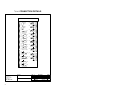
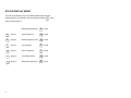
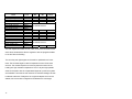
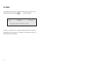
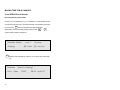
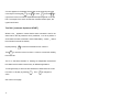
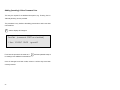
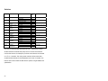
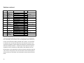
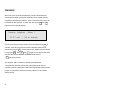
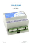
AMBIFLEX focus - SERVICE MANUAL
CONTENTS
Page No
2
focus Overview
focus Connection Details
3
Technical Specification
4
Unlocking & Locking the focus
Status Display Mode
1
7
9
User Adjusts
11
Alarms/Eventlist
13
Optimes
14
Time Scheduling - Reviewing
15
Time Scheduling - Editing
19
Time Scheduling - Inserting
23
Calendar Scheduling - Reviewing
24
Calendar Scheduling - Editing
24
Calendar Scheduling - Inserting
24
Time Setting - Clock Adjustment
26
Time Setting - British Summer Time
27
System Configuration - Switches
28
Commissioning
31
Service Tick Sheet
33
Service Record
35
Menu Map
36
focus PRODUCT OVERVIEW
The focus is an intelligent standalone or networking building management
system with features normally available only in much more expensive
systems.
It has been designed with override and adjustment facilities for the non
technical user.
The focus incorporates a separate PSU board with field connection
terminals which connects to the front panel/CPU via a ribbon cable. This
means site installation can be carried out without the risk of damaging the
front panel/CPU which can be fitted at the commissioning stage.
The front panel has a Keypad/LCD display which can show temperatures,
alarms and generally what is happening with the system at the two ‘User’
levels and can be used for commissioning at the two ‘Engineer’ levels. All
levels except the lowest user level are password protected.
A modem may be plugged directly into the RS232 port of the PSU
allowing automatic dial-out of alarm messages to a PC or standard off the
shelf fax machine.
This guide concerns the Service level of access to the controller, which is
the lower of the two engineer levels. This booklet should be used when
servicing and maintaining the focus.
2
focus CONNECTION DETAILS
focus Address - 1
1
L
2 N
35
AI 1
240V AC
Supply
36
3 E
37
4 L
5 N
6 E
39
40
6A screen
7
8
11
DO
1
42
43
AI 4
44
DO
2
45
46
47
AI 5
11A
12
41
AI 3
9
10
38
AI 2
Auxiliary
Supply
DO
3
48
49
13
14
15
DO
4
AI 6
DO
5
AI 7
50
51
52
16
17
18
19
20
53
54
DO
6
55
56
AI 8
57
21 Energising Voltage
58
22
23
DI 1
AO
1
DI 2
AO
2
24
59
60
25
26
27
61
62
63
28 Energising Voltage
64
29
30
DI 3
31
32
33
DI 4
34
Ambiflex Ltd
5 Vale View
Vicarage Lane
Bowdon, Cheshire
WA14 3BD
Tel : 0161 941 1122
Fax : 0161 941 1188
3
Project
Rev
Description
Date
Customer
focus
Sheet No 1 of 1
TECHNICAL SPECIFICATION
focus Inputs
8 -
Analog Inputs (Temperature Sensors).
4 -
Digital inputs for remote overrides and plant fault.
4 -
Dedicated Inputs on front panel for setting extension timers,
summer/winter selection and holiday operation selection.
1 -
Dedicated Alarm Mute input on front panel.
focus Outputs
6 -
Digital outputs.
2 -
0…10V dc analog outputs.
The 0…10V outputs can be used for control of a mixing valve and also a
boiler sequencer.
For systems requiring greater input/output capacity than that provided by
the focus, the MF820 from Ambiflex offers a fully expandable system.
4
Energy Management
3 Time Channels for heating, hot water and an independent time channel
fixed start/stop time
optimum start/stop time - heating
each day of the week independently programmable
Pre-programmed minimum on/off/step time delays for boiler control.
Integrated demand boiler control.
Control
Setpoint generators for weather compensation, cascade control etc.
4 P + I control output loops
Loops 1 & 2 via on board relays
Loops 3 & 4 via 0 … 10V onboard outputs
Boiler sequencing of up to 2 boilers with optional equalised run time (ERT)
5
Monitoring
3 Data logs (trend logs)
one energy log with degree days.
two temperature logs, 8 temperatures/calculated temperatures
plus time/date
Event (alarm) recording
6
UNLOCKING AND LOCKING THE focus
TO UNLOCK
Press
#
9
)
to make sure the focus is in the standby display mode.
+ )
The focus display will change to:
Access
Unlock
??????
Locked
Key [9] to open
and the cursor moves to the bottom line over the leftmost ‘?’
SERVICE LEVEL UNLOCK
Enter the low level password. If left at its default setting enter
display as follows:
1
2
3
1
2
3
or appropriate password if this has been changed.
As each key entry is made, the ‘?’ changes, starting with the rightmost ‘?’
to #.
When all six digits have been entered: # +
7
0 twice to accept.
If entered correctly, the display will change to:
)
Access
Unlock
??????
open, service
to return to standby display, or key 1
then 5
to get to Time
Scheduling, the first menu heading.
LOCKING THE focus
The focus will lock itself automatically 20 minutes after the last keystroke.
To lock it before this (starting from the standby display).
# +
)
8
)
then
3
9
5 then
to revert to standby display.
# +
0
STATUS DISPLAY MODE
The user can go directly to any of the status display pages from the
standby display, in the locked or unlocked mode by pressing 0
goes to the first page, i.e.
:
9
Measured temperatures
#
to view
5
goes to :
Time channel info.
#
to view
5
again to :
What is happening now?
#
to view
5
again to :
Any problems?
#
to view
5
again to :
Info for engineers.
#
to view
5
again to :
Accumulator values
#
to view
5
again to :
Measured temperatures
#
to view
which
DISPLAY MENUS
A wider range of information regarding the status of the focus can be
displayed in more detail whilst the machine is unlocked as follows:
0
The display will change to:
User
Display
[#] = view
Measured temperatures
[5] = Channel info. [)] = escape
The first status display concerns the measured temperatures allocated on
the controller and targets - repeatedly pressing # will show all of these.
The second menu concerns Time channel information, ie. information
concerning the current status of the heating, hot water etc. repeatedly
pressing
# will show all current information. The ‘What is happening
now?’, ‘Any problems?’, ‘Info for engineers.’ and ‘Accumulator values’
menus show current status readings, faults, problems and any other
details eg. run hours for boilers. When a section has been chosen
repeatedly pressing
menu.
10
# shows all the values/information within that
USER ADJUSTS
#
From the default display press
hold and press 0 . These keys
pressed together will take the user directly to this screen.
User
Adjust
21.0
To change this
21.0
Room day target
[9]=change
9
[5]=nxtAdj
and the bottom line of the display changes to:
[ 2=Up
5=Down
0=Reset
#ok ]
2
takes the temperature up by half a degree.
5
takes the temperature down by half degree.
0
takes the temperature to the default programmed in.
#
accepts the changes made.
#
again to return to normal display.
When the cursor is flashing over Room day target,
cursor to the next setpoint.
11
5
will move the
Name
Room day target
Room night target
Hot water target
Off above - outdr temp
Outdoor @ high VT temp
Normal high VT temp
Outdoor @ low VT temp
Normal low VT temp
VT parallel shift
VT night shift
Max VT flow limit
Min VT flow limit
Maximum boiler flow
Minimum boiler flow
Room FROST cut in
Outdoor FROST cut in
Boiler FROST cut in
OFF above room-SP
Level
Free
Free
Free
User
Installer
Installer
Installer
Installer
Service
Service
Service
Service
Service
Service
Installer
Installer
Installer
User
Max
30
30
60
36
Min
16
16
35
-10
Default
21
21
55
35
Not available at this level see Installer manual
20
0
83
80
87
87
-25
-25
50
15
50
35
0
-10
80
30
83
50
Not available at this level see Installer manual
5
0
2
The user adjusts earmarked for Free, User, and Service can be accessed
at this level, this allows the Service engineer to trim the program installed
to suit the client and building.
The room day and night targets can be used for optimisation and room
reset. The hot water target is used for temperature control of hot water
services. The outdoor setpoint is an economy feature to switch off the
heating at a high outside air temperature. The VT day and night parallel
shifts can be used to trim the compensated slope set up when the system
was installed. The maximum and minimum VT and boiler settings can also
be altered at this level. Finally there is a high limit setpoint which can be
altered, this is the number of degrees to be added to the room target.
12
EVENTLST
Press and hold the
# and the 0 together to get to the User Adjust
display then move the cursor over Adjust by pressing
1 then key
5
and this display appears:
User
[#] = view
Press
#
Eventlst
[5] = U/Optims
to view the alarms and events on this list. The name of the
alarm appears along with the time that the alarm occurred and the time
that it cleared.
Key
13
5 to view the next menu heading ‘Optimes’.
OPTIMES
The Optimes menu shows all optimised start and stop times for the
heating channel up to 50 events. Press
#
User
Optimes
to view the events.
Channel 1
0] Opt start 07:18 Thu 13th
If there is no event line for a day this means that there has been no
optimised start for that day ie. the system only started up when the
programmed occupancy begins.
14
TIME SCHEDULING
For most day to day operations it is not necessary to make changes to the
Time Schedule settings. This is because override facilities are provided
by the 4 black pushbuttons - Heating Extend, Hotwater Extend, Summer
Switch and Holiday Switch.
If however, it is necessary to modify time switching commands
programmed at the commissioning stage, this can be done by the service
engineer when the focus has been unlocked. This procedure was
explained earlier (see Page 7).
SERVICE LEVEL
At this level the service engineer is allowed access to:
1.
Change any existing switching times for days already programmed.
2.
Add new switching times.
3.
Delete existing time switching commands.
15
MAKING TIME TABLE CHANGES
From SERVICE Level Access
Reviewing Existing Time Tables
Unlock focus as explained in ‘focus Lock/Unlock’. The time table menu is
one below the Access menu. Therefore with the cursor flashing over the A
for Access key
5
and the TimeTabl menu will be reached.
Alternatively, from the standby display position press
# +
2
together and the display changes to:
TimeTabl Review
Heating
chnl 1
Any day
[#] = view [5] = nxt chn
# View the time schedule for channel 1 on for every day of the week
e.g.
Timsched
[time ch: Heating]
Chn 1 Opsrt
16
12345 . .
08:30 xcpt LG1
A cursor appears on the bottom line and this can be moved by using the
cursor keys on the keypad, 2 is up, 5 is down,
1 is left and 3
is
right. As the cursor is moved an expanded description appears on the top
line. For example, if the cursor is under the command section Opsrt, the
upper line will read
TimeTabl [command: Optimised START]
Where a dot ‘.’ appears it means that the same command is set for the
same time for the day where the dot is positioned, i.e. a dot in position 3
would mean the same command is set for Wednesday. A dash ‘_’ means
the command is not set for that day.
Repeat pressing
Then 5
#
to view all command lines for channel 1.
to move the cursor from Chnl 1 to Chnl 2 to view other existing
time channels.
The focus has three channels, i.e. Heating, an Independent Channel and
Hot Water but the number used will vary for different applications.
To change the day on which the time schedule is viewed move the cursor
from Chnl 1 to Anyday by pressing
value.
See chart on next page.
17
3 .
Then
5 to change this
Any Day
18
5
Goes to:
Week Days
5
Goes to:
Weekend
5
Goes to:
Mon (1)
5
Goes to:
Tues (2)
5
Goes to:
Wed (3)
5
Goes to:
Thu (4)
5
Goes to:
Fri (5)
5
Goes to:
Sat (6)
5
Goes to:
Sun (7)
Changing Existing Switching Times
Once the required Time Channel has been selected, carry out the review
procedure for that channel for ‘Any day’ by repeatedly pressing
#
until the line to be changed appears on the bottom line of the display.
Move the cursor over the current switching time by pressing key
3
then:
9
And the cursor will move to the left hand digit of the time currently
set.
h
e.g.
h
m
0
to enter the new switching time.
m
7
4
5
would set a time of 07:45 (24 hour format).
Once the correct time has been set, it can be entered into the system by
pressing
#
+
0
together once.
Then #
to move to the next
command line.
To make changes to other time channels, select the required channel by
scrolling ( 5 or
19
2 ) whilst the cursor is on the top line next to ‘chnl’.
Changing Existing Time Command Lines
Once the required channel has been reviewed, and the first command
line to be edited has been selected
TimeTabl
Chn 1 Opsrt
Command
9
[command: Optimised START
12345 _ _
07:30
Days Viewed
Time
]
xcept LG 1
Except Link Group
1 Holiday Dates
and the cursor will move to the time command type on the
left hand side of the bottom line of the display.
If the command type is to be changed, scroll using 5 or 2 until
the new command type has been selected.
20
The command type may be chosen from the list below:
‘Start’
This means switch on at the time set for the days
programmed.
‘Opsrt’
Which means an optimised start to reach the target
temperature at the time displayed.
‘Stop’
This means switch off at the time set for the days
programmed.
‘Opstp’
This means switch off before or at the time set providing
the target end temperature will be met.
‘Cycle’
This is a start command which means go into proportional
load cycle mode at the time set (not used with this set of
applications).
‘Pulse’
Currently this command is not in use.
Then back to Start.
Then
# +
0 and the cursor will move to the ‘day’ selections.
To add a day which is not already programmed, enter the day key
number,
e.g.
21
1 adds day 1 (Monday).
If the day is already programmed, entering the day number will remove it.
e.g. if display shows
‘1 2 3 4 5 _ _’
removes day 4 (Thursday) and display
4
becomes
‘1 2 3 _ 5 _ _’
4
again restores day 4.
0
removes all days which if accepted deletes that command
line.
9 adds all days.
#
+
0
to accept the required day combination and the cursor
moves onto ‘time’.
Enter new time, if required, as in Low Level.
# +
0 to accept the new time and the cursor moves to the Link
Group column, this is to link in the time schedule to the
holiday dates entered.
The selections here are:
Ignore LG1 – generally used for Stop and OpStop commands.
Only LG1 – used only for times which are set in during a holiday.
Except LG1 – generally used for Start and OpStart commands.
To select use
22
5
or
2 key.
Adding (Inserting) A New Command Line
This may be required if an additional time period, e.g. ‘Evening Use’ or
‘Saturday Working’ is to be provided.
The procedure is very similar to the editing process but to add a new time
command line:
7
and the display will change to:
TimeTabl [command: START as scheduled]
1 Start 1234567 00:00
ignoreLG
From here the process is the same as if
9 had been pressed except it
is creating a new additional command line.
Once all changes have been made, review to confirm they have been
correctly entered.
23
CALENDAR SCHEDULING - DIARY
At SERVICE level existing dates for suspending and restoring daily time
schedules may be changed.
CHANGING EXISTING CALENDAR DATES
As a standard convention, all focus controllers are set where:
Holiday makes all channels inactive i.e. suspend all daily time
programmes starting on this date i.e. the first day of holiday and
date of the holiday i.e. normal operation resumes the day after.
Return to the standby display by pressing ) . Then by pressing:
#
+
3
the display will show typically:
Diary Review
[#]=view
24
[5]=D.Logs
[7]=add
After reviewing existing dates, review again until the first date to be
changed is displayed then:
9
then select event required ie. Holiday
# +
0
to accept. Then key in the start date, this is in
Date/Month/Year format. If only the Date and Month are
entered then this event will occur every year, otherwise if
a specific year is entered, the event will be deleted once it
has occurred.
#
0
+
to accept. Then key in the date for the last day of holiday
operation.
E.g
A holiday like Christmas Day and Boxing Day
occurring every year could be entered as:
Holiday Cal: all OFF 25/12/xx to 26/12
#
+
#
0
to accept.
to move to the next event to be edited.
Carry on until all dates have been reviewed, changed and
accepted.
N.B.
CALENDAR DATES CAN ROLL ON CONTINOUSLY OR BE
YEAR SPECIFIC.
Inserting new calendar dates follows exactly the procedure above with one
exception - instead of using key 9 , key 7
25
is pressed.
TIME (CLOCKTIME) SETTING
Clock Adjustment
Changing clock times can be done at the SERVICE Level of access (see
Page 7 for unlock instructions) in the Timekeep Clockset Menu. This
menu can be reached by pressing
#
and
7 together from the
default display.
9
and the cursor moves to the time at the bottom left hand side of
the display.
h
h
m m
to enter correct time, then # +
d
d
m m
y
#
+
0
y
to enter date including year
and then clock will update the ‘Day’ and ‘BST’
automatically.
26
0
BRITISH SUMMER TIME (BST)
The default for the BST start date is set with the month only, e.g. 00/03 for
March the focus will change from Winter to Summer Time automatically at
02:00 on the last Sunday in March, every year. The GMT start date is
also set with the month only, e.g. 00/10
Occasionally this will be wrong for a period of 1 week in some years when
the time change takes place on the Sunday before the last Sunday in the
month.
9 to edit and key in
# and 0 together to
Specific dates can be set within the controller, key
the date in the day/month format then press
update the controller.
27
SYSCONFG
From the stand-by display press
#
and
6
together to access the
following display:
Sysconfg ConfigSw DHW-plant setup
ON — with DHW
Within this menu the application configuration switches can be accessed;
these switches should be checked for the application installed and the
current building usage.
Be aware that choice of switch position determines how the controller will
operate and may limit access, for example, if the first switch DHW-plant
setup is set to the OFF position, the next three switches will be
automatically turned OFF and shown ‘Not currently in use’.
Not all switches are relevant in all of the applications, so there are pre-set
settings for switches which are not required. In the following tables this is
shown:‘H-F’ - OFF and hidden by the application, ‘H-N’ - ON and hidden by the
application.
28
Switches
Switch:
Name:
On/Off Name:
Cg 01
DHW-plant setup
Cg 02
DHW-control
Cg 03
DHW-heat
source
DHW-secondary
pump
Sensor-room
sensor 1
Sensor-room
sensor 2
Sensor-room
sensor 3
Sensoraveraging
Sensor-boiler
return
Heating-MV
override
Heating-setback
-no DHW
-with DHW
-with time only
-with time & temp
-independent heater
-with link to boiler
-no pump
-slaved with R6
-not required
-included
-not required
-included
-not required
-included
Cg 04
Cg 05
Cg 06
Cg 07
Cg 08
Cg 09
Cg 10
Cg 11
Cg 12
Heatingoptimisation
-not required
-included
-not required
-included
If
SET
to:
Off
On
Off
On
Off
On
Off
On
Off
On
Off
On
Off
On
Off
On
Off
On
Off
On
Off
On
Off
On
Applications:
1,2,3,4,5,6
1,2,3,4,5,6
1,2,3,4,5,6
H-N,H-N,H-N, H-N,5,6
1,2,3,4,5,6
1,2,3,4,5,6
1,2,3,4,5,6
1,2,3,4,5,6
1,2,3,4,5,6
H-F,H-F,3,4, 5,6
1,2,3,4,5,6
1,2,3,4,5,6
The first four switches deal with DHW services – requirement, control,
whether linked to the boiler and pump control. The next five switches
concern the sensors, for example up to three room sensors can be used
on a focus controller. The mixing valve override, will force the valve
closed should the boiler circuit temperature be too low, if included. The
last two of this set of switches deal with the options of night setback and
optimisation.
29
Switches continued
Switch:
Name:
On/Off Name:
Cg 13
-no room reset
-With room reset
-room:flow ratio 3:1
-room:flow ratio 2:1
Cg 19
Heating-flow
target
Heating-reset
ratio
Ch 2-Ind.
timer
Ch 2-link to
heating
Ch 2-link to
DHW
Boiler-control
setup
Boiler-firing
Cg 20
Boiler-rotation
Cg 21
DHW-cylinder
control
DHW-htg
primary pump
Not currently
in use
Sensormonitoring
Cg 14
Cg 15
Cg 16
Cg 17
Cg 18
Cg 22
Cg 23
Cg 24
-No link
-works with heating
-No link
-works with DHW
-Single boiler
-0..10v sequencer
-Fixed firing
-Sequence rotates
-equal run time
-weekly rotation
-no control valve
-with control valve
-no pump control
-with pump control
Not currently in use
Not currently in use
If SET
to:
Off
On
Off
On
Off
On
Off
On
Off
On
Off
On
Off
On
Off
On
Off
On
Off
On
Off
On
Off
On
Applications:
1,2,3,4,5,6
1,2,3,4,5,6
1,H-F,3,H-F, 5,H-F
1,H-F,3,H-F, 5,H-F
1,H-F,3,H-F, 5,H-F
1,H-F,3,H-F, 5,H-F
H-F,2,H-F, 4,H-F,6
H-F,2,H-F, 4,H-F,6
1,2,H-F,H-F, H-F,H-F
1,2,H-F,H-F, H-F,H-F
1,2,3,4,5,6
1,2,3,4,5,6
The first two switches deal with room reset - the influence the room temperature
has on the heating. The next three concern the Independent Time Channel (ITC),
the ITC can be linked to the heating, the DHW, both or neither – this is generally
for extensions etc. The next three switches are to do with boiler control, on the
single boiler applications and the multiple boiler applications. With fixed firing the
lead boiler will always be Boiler 1, if sequencing is chosen there is the option for
equalised run time on the boilers or weekly rotation of the lead boiler. The two
DHW switches concern temperature control and how that is achieved, through the
control valve or through pump control. The last switch concerns monitoring of the
sensors picked up on the system, if this is left ON the controller will record sensor
failure.
30
CMISSION
Within this menu all inputs (temperatures, remote override fault) and
outputs (boilers, DHW, pumps) etc real status can be viewed and also
simulated to test different conditions. There is also a fast clock which can
be initiated for test purposes. To reach this menu press
# and
8
together from the standby display.
Cmission AnlgSimu
21.0`C real
Room 1
: [9] to override
Use the cursor keys to choose which point to simulate then key 9
to
override; a test value can then be entered. Negative values can be
entered by keying all
by keying all
9 , positive values from negative can be achieved
0 . Then
# and 0 together to accept the new value.
The test value can be altered to suit as described above or
7
will cancel the test.
The AnlgSimu menu contains the Analog Inputs (Measured
Temperatures); BininSim contains the binary/digital inputs (remote
overrides, faults etc); RelaySim contains the relays/digital outputs (boilers,
pumps, etc); AnoutSim contains the analog outputs (VT valve, boiler
sequencer etc).
31
The BininSim and RelaySim menus which deal with the digital points show
the condition of the point as either ‘Set’ or ‘Clear’. ‘Set’ equates to
energized/closed contact and ‘Clear’ to de-energised/open contact i.e. if
Boiler 1 condition is set then it is energized off. Therefore on controller
failure the boilers will fail on.
Lastly the commissioning section contains a test clock feature to enable
the Service/Commissioning engineer to test out time schedules and
calendar schedules.
Cmission Testclok
clear
The testclok can be run in:
mins+ 1
mins+ 5
mins+ 10
mins+ 30
Date+ 1
N.B.
Remember to reset the above features when testing is
concluded.
32
SERVICE TICK SHEET
Client:
Site Address:
SERVICE CHECKS (tick
as applicable)
CONTROLLER Check door seals and
ingress of dirt/moisture into
the panel
Test door interlocks, switch
operations and indicators
Check controller power
supply route; fuses, MCB’s,
earth connection and any
special supply detail such
as RFI filter, voltage
transformer, isolating
transformer
Check display and keypad,
key actions and backlight
settings
Check tightness of
terminations and cable
security
Check network (RS232)
and sub-network (RS485)
communications buses for
error free operation
INPUTS/OUTPUTS Check temperature
sensors for mechanical
damage, integrity of wiring.
Confirm correct sensor
allocation against
programmed reference
point
33
Visit 1
Visit 2
Visit 3
Visit 4
Visit 5
SERVICE CHECKS (tick
as applicable)
Check correct operation of
controlled devices.
Check digital inputs for
correct operation and
interlocking action with
controlled devices
Check digital output relays
for correct operation and
interlocking action with
controlled devices (boilers,
pumps, valves etc)
SOFTWARE/PROGRAM
FUNCTIONS Check time/calendar
schedules, step through
days/weekend operation
Check operation of
local/remote override
switches and remote
indication
Check system software,
application, configuration
switches set correctly
Check clock setting, day
and date
Check data logs and event
list for reporting
Down load temperature
data logs and review for
performance
Copy latest settings for
program back-up
Consult with client for any
operational changes
required to system
parameters/adjustments
34
Visit 1
Visit 2
Visit 3
Visit 4
Visit 5
SERVICE RECORD
Client:
Site Address:
Visit
1
2
3
4
5
Job Reference No:
Visit
1
2
3
4
5
Reason for visit:
Visit
1
2
3
4
5
Recommendations:
Visit
1
2
3
4
5
Client Signature:
35
Customer Order No:
Engineer Signature:
Date:
Focus Menu Map
User
Action
Holiday all OFF dd/mm etc
Display
Measured temperature etc
Adjust
Room day target etc
Eventlst
OpTimes
Access
Lock
Unlock
TimeTabl
Review
Heating
Anyday etc
DLinkStat
Diary
Review
Status
Datalogs
View
#1 Daily etc
Sysconfg
ConfigSw
DHW - plant setup etc
Timekeep
Clockset
BST dates
Cmission
AnlgSimu
BininSim
RelaySim
AnoutSim
Testclok
36
The above is for SERVICE access.