1
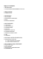
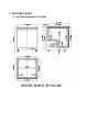
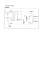
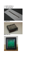
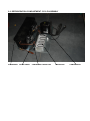
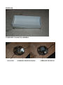
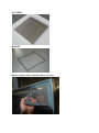
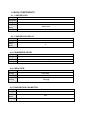
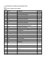
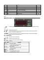
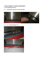
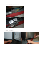
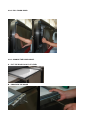
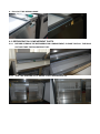
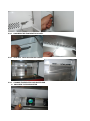
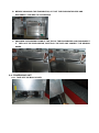
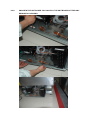
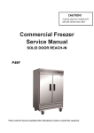
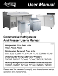
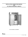
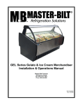
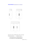
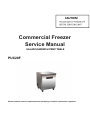
Commercial Freezer
Service Manual
SALAD/SANDWICH PREP TABLE
PUC28F
Please read this manual completely before attempting to install or operate this equipment.
TABLE OF CONTENTS
1. FEATURE CHART
1-1. OUTSIDE DRAWING AND MEASUREMENT FOR PUC28F
2. WIRING DIAGRAM
2-1. FREEZER: PUC28F
3. PARTS DETAILS
3-1. BOTTOM PANEL
3-2. REFRIGERATION COMPARTMENT
3-4. DOOR
3-5. COOLING COMPARTMENT
4. MAIN COMPONENTS
4-1. COMPRESSOR
4-2. COMPRESSOR RELAY
4-3. CONDENSER DRYER
4-4. CAPACITOR
4-5. EVAPORATOR FAN MOTOR
4-6. CONDENSER FAN MOTOR
4-7. EVAPORATOR DEFROST HEATER
4-8. LAMP
4-9. THERMOSTAT
5. ELECTRONIC CONTROLLER INSTRUCTION
5-1. REFRIGERATOR CONTROLLER
5-1-1. DIXELL PARAMETER FOR FREEZER
5-1-2. HOW TO USE THE CONTROLLER
6. REPLACEMENT OF MAIN COMPONENTS
6-1. FRONT PANEL PARTS
6-2. DOOR CHANGING
6-3. REFRIGERATION COMPARTMENT PARTS
6-4. CONDENSING UNIT
1. FEATURE CHART
1-1. OUTSIDE DRAWING OF PUC28F
2. WIRING DIAGRAM
2-1. PUC28F
3. PARTS DETAILS
3-1. BOTTOM PANEL
THERMOSTAT
MAIN SWITCH
3-2. REFRIGERATION COMPARTMENT CYCLE ASSEMBLY
CONDENSER
FILTER DRIER
CONDENSER FAN MOTOR
WATER PAN
COMPRESSOR
DRAIN PAN
CONDENSER FAN MOTOR ASSEMBLY
FAN COVER
CONDENSER FAN MOTOR BLADE
CONDENSER FAN MOTOR
3-3. DOOR
GASKET
Magnetic gasket can be replaced without any tools.
4. MAIN COMPONENTS
4-1. COMPRESSOR
MODEL
PUC28F
Refrigerant
R-404A
Voltage
Comp.
Model
Part code
115V/60Hz
NEK2134GK
TUC27F.07
4-2. COMPRESSOR RELAY
PUC28F
Voltage
Relay
Model
115V / 60Hz
X
4-3. CONDENSER DRYER
MODEL
PUC28F
Refrigerant
R-404A
Spec.
Part code
XH-9
25g
GN1410TN.14
4-4. CAPACITOR
MODEL
PUC28F
Voltage
115V / 60Hz
Running
X
Starting
189-227μf
4-5. EVAPORATOR FAN MOTOR
MODEL
PUC28F
Voltage
115V / 60Hz
Motor
Model
Part code
1238
TUC27.31
4-6. CONDENSER FAN MOTOR
MODEL
PUC28F
Voltage
115V / 60Hz
Motor
Model
BD03-04/C06
Part code
54F.09
4-7. EVAPORATOR DEFROST HEATER
MODEL
PUC28F
Voltage
115V / 60Hz
Spec.
Part code
500
TUC27F.04
4-8. LAMP
MODEL
PUC28F
Voltage
115V/60Hz
Spec.
Part code
-----
4-9. MAIN PCB
MODEL
PUC28F
Voltage
115V / 60Hz
Model
XR60C
Part code
27F.11
5. ELECTRONIC CONTROLLER INSTRUCTION
5-1-1.
DIXELL XR60C PARAMETER FOR FREEZER
PUC28F
NO.
CODE
PARAMETER
SET(℉)
1
Set
Main Set point
-7
2
Hy
Differential(hysteresis)
4
3
LS
Lower limit of main set point
-11
4
US
Upper limit of main set point
-1
5
Ot
Offset
-1
6
P2P
Evaporator probe presence
Y
7
OE
Evaporator probe calibration
8
P3P
Condenser probe presence
Y
9
P3F
Condenser probe function
Au2
10
O3
Condenser probe calibration
0
11
Ods
Outputs delay at start up
0
12
AC
Minimum time interval between the deactivation and
successive activation on compressor
5
13
CCt
Continuous cycle duration
0
14
Con
Compressor on-time during probe failure
10
15
COF
Compressor off-time during probe failure
10
16
CF
Unit of measure
℉
17
rES
Resolution
dE
18
Lod
Probe displayed
P1
19
tdF
Defrost type
EL
20
dtE
Defrost-end temperature
45
21
IdF
Time interval between defrost cycle
6.0
22
MdF
Max defrost cycle time
20
23
dSd
Start defrost delay
0
24
dFd
Displaying during defrost
it
25
dAd
Real temperature display delay at defrost end
0
26
Fdt
Dripping time
2
27
dPo
First defrost cycle after controller start up
n
28
dAF
Defrost delay after fast freezing
0
29
Fnc
Fan operating mode during normal controller
30
Fnd
Fan activation delay at controller startup and after
defrost
2
31
FSt
Fan stop temperature
54
32
ALC
Temperature alarms configuration
rE
33
ALU
Max temperature alarm differential
90
34
ALL
Minimum temperature alarm differential
0
0.0
o-n
35
ALd
Minimum or minimum temperature alarm delay
99
36
dAO
Delay of temperature alarm at start up
1h
37
AU2
Condenser alarm temperature
144
38
ACH
Condenser alarm differential
8
39
Ad2
Condenser alarm delay
0
40
dA2
Delay of condenser temperature alarm at start up
0
41
AC2
Compressor stop for condenser alarm
AUt
42
Pbc
Kind of probe
ntc
5-1-2.
1. FRONT PANEL COMMANDS
To display target set point. Select a parameter or confirm an operation in programming
mode.
To start a manual defrost
To view the last alarm occurrence; in programming mode, it browses the parameter
codes or increases the display value
To view the last alarm occurrence; in programming mode, it browses the parameter
codes or decreases the display value
KEY COMBINATION
To lock & unlock the keyboard
To enter in programming mode
To return to the room temperature display
1.1 Function of LEDS
2. MAIN FUNCTIONS
2.1 HOW TO VIEW THE SET POINT
1. Push and immediately release the SET key: the display will show the set point value.
2. Push and immediately release the SET key or wait for 5 seconds to display the
sensor value again.
2.2 HOW TO CHANGE THE SET POINT
1. Push the SET key for more than 2 seconds to change the set point value.
2. The value of the set point will be displayed and the
LED starts blinking.
3. To change the set value, push the
or
key within 10s.
4. To set new point value, push the SET key again or wait 10s.
2.3 HOW TO START A MANUAL DEFROST
Push the
key for more than 2 seconds and a manual defrost will start
2.4 HOW TO LOCK THE KEYBOARD
1. Hold the
and
keys for more than 3s.
2. The “POF” message will be displayed and the keyboard will be locked. At this point, it will be
possible only to see the set point or the MAX or Min temperature stored.
3. If a key is pressed more than 3s the ”POF” message will be displayed.
2.5 HOW TO UNLOCK THE KEYBOARD
Hold the
and
keys together for more than 3s, till the “POF” message is displayed.
3. ALARM SIGNALS
HOW TO VIEW THE ALARM AND
RESET THE RECORDED ALARM
1. Hold the
or
key to
display the alarm signals.
2. When the signal is displayed, hold
the SET key until the “rst” message
is displayed. Push the SET key
again. The “rst” message will start
blinking and the normal temperature
will be displayed again.
6. REPLACEMENT OF MAIN COMPONENTS
6-1. BOTTOM PANEL PARTS
6-1-1. UNSCREW BOTH SIDES OF THE BOTTOM PANEL
6-1-2. PULL THE BOTTOM PANEL OUT
6-1-3. UNSCREW THE JUNCTION BOX
6-2. DOOR CHANGING
6-2-1. UNSCREW THE BOTTOM HINGE
6-2-2. PULL DOWN DOOR
6-2-3. CHANGE THE DOOR HINGE.
A. PUT THE DOOR ON A FLAT LEVEL
B. UNSCREW THE HINGE
C. PULL OUT THE SPRING HINGE
6-3. REFRIGERATION COMPARTMENT PARTS
6-3-1. BEFORE OPENING THE REFRIGERATION COMPARTMENT, PLEASE TAKE ALL THE PANS
OUT AND TAKE THE PAN SUPPORT OFF.
6-3-2. TAKE THE SHELVES OFF, K SHAPE CLIPS, AND SENSOR OFF
6-3-3. UNSCREW THE EVAPORATOR COVER.
6-3-4. TAKE OFF THE EVAPORATOR COVER
6-3-5. CHANGE EVAPORATOR AND WATER PAN
A. UNSCREW THE EVAPORATOR
B. BEFORE CHANGING THE EVAPORATOR, CUT OFF THE EVAPORATOR PIPE AND
DISCONNECT THE WIRE TO THE SENSOR.
C. UNSCREW THE SCREWS FOUND AT THE TOP OF THE EVAPORATOR, AND DISCONNECT
IT. REPLACE THE EVAPORATOR, REATTACH THE PIPE AND CONNECT THE SENSOR
WIRES.
6-4. CONDENSING UNIT
6-4-1. TAKE OFF THE BACK COVER.
6-4-2.
UNSCREW THE UNIT BOARD. YOU CAN PULL THE UNIT BOARD OUT FOR ANY
REPAIRS OR CLEANING.
CAUTION: BE CAREFUL OF ELECTRIC SHOCK
CAUTION: MAKE SURE THE POWER SUPPLY IS CUT OFF
BEFORE ANY SERVICE IS PERFORMED.
CAUTION: CONDENSING UNIT MAY BE VERY HOT. BE SURE
IT IS COOL BEFORE ANY SERVICE IS PERFORMED.