1
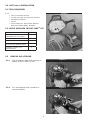
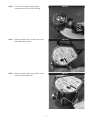
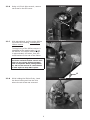
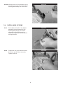
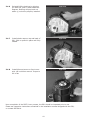
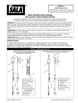
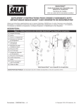
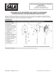
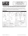
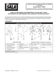
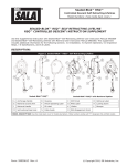
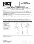
Sealed-Blok™
FAST-LineTM Replacement Lifeline
Model Numbers: See Figure 1.
Service Manual for
Sealed-Blok™ Fast-LineTM Replacement Lifeline
WARNING: This product is part of a personal fall arrest system1. The user must read and follow the
manufacturer’s instructions for each component or part of the complete system. Manufacturer’s instructions
must be followed for proper use and maintenance of this product. Alterations or misuse of this product or failure
to follow instructions may result in serious injury or death.
1
IMPORTANT: If you have questions on the use, care, or suitability of this equipment for your application,
contact Capital Safety.
description:
FAST-LineTM is a field-replacement lifeline for the Sealed-Blok™ SRL Fall Arrest System1. See Figure 1 for
Fast- LineTM Kit numbers and descriptions.
Figure 1 - FAST-LineTM Replacement Lifeline Kit
Fast-LineTM Kit Number
Description
3900105
50 feet of 3/16 inch galvanized wire rope, self locking plated steel swiveling snap hook with indicator.
3900106
50 feet of 3/16 inch stainless wire rope, self locking plated steel swiveling snap hook with indicator.
3900107
50 feet of 3/16 inch stainless wire rope, self locking stainless steel swiveling snap hook with indicator.
1 Fall Arrest System: A system that prevents the worker from colliding with an obstruction or lower level by arresting a fall.
Form: 5903076 Rev: A
© Copyright 2010, DB Industries, Inc.
1.0table of contents
Subject
SectionPage
APPLICATION
1.0
3
Purpose
1.1
3
About this Manual
1.2
3
Service Questions
1.4
3
Errors and Omissions
1.6
3
Service Procedures
2.0
3
2.1
3
Fast-LineTM Installation
3.0 4
Tools required
3.1
4
Parts included
3.2
4
Remove old lifeline
3.3
4
Install new lifeline
3.4
8
4.0
11
Pre-Service Inspection
Lifeline replacement log
2
1.0application
1.1
PURPOSE: This manual is intended for use by competent individuals properly trained in the
procedures contained herein, and authorized to perform service work. No distribution or
duplication by any means is allowed without the written permission of DBI/SALA.
Warning: In most cases, replacing the lifeline cannot be considered as a complete servicing. A
thorough inspection of the unit must be performed by a competent person, according to section 5.0
of the Sealed-Blok™ Self Retracting Lifeline User Instruction Manual, form 5903059. If the snap
hook impact indicator shows signs of activation (refer to the User Instruction Manual), the unit
should be removed from service and fully serviced, including the brake and the other internal safety
components. If it is known that the impact indicator is activated but that the unit has not been used to
arrest a fall (retrieval situation for example) then it is acceptable that only the lifeline gets replaced,
as long as the rest of the unit passes the inspection procedures in Section 5.0 of the User Instruction
Manual.
1.2
ABOUT THIS MANUAL: The written service procedures contained in this manual are
supplemented by figures and drawings. Figures are designated by Figure numbers and are
located adjacent to the relevant text. When reference is made to an item within a Figure, the
reference includes a description and an underlined item number (i.e. specification label 15).
1.3
SERVICE QUESTIONS: If additional service information is required contact a DBI/SALA
technical service representative.
1.4ERRORS AND OMISSIONS: DBI/SALA has made every effort to ensure that the information
in this manual is correct and complete. Please contact DBI/SALA if errors are found.
2.0
Service Procedures
WARNING: Some service procedures in this manual can be hazardous, and may result in serious
injury. It is recommended that persons engaged in service work wear suitable clothing and proper
hand, eye, face, and foot protection as necessary.
WARNING: Use of parts, materials, or procedures not specified or supplied by DBI/SALA may
be dangerous, and could result in death or serious injury to the user. Only genuine DBI/SALA
replacement parts may be used.
2.1
TOOLS: A list of required tools for FAST-LineTM is presented in Section 3.0, Fast- LineTM
Installation.
NOTE: Torque measuring service tools must be maintained in correct calibration, traceable to the
National Bureau of Standards
2.2PRE-SERVICE INSPECTION: Before beginning the FAST-LineTM cable replacement
procedure, a functional inspection of the Sealed BlokTM unit should be performed. This
may reveal an otherwise undetected defect. Refer to Section 5 Inspection Procedure in the
Sealed-Blok™ Self Retracting Lifeline User Instruction Manual.
It is recommended that service records be kept on permanent file. This information should
include: Model number, serial number, date of service, condition prior to service, parts
replaced by part number, lot numbers of applicable parts, and condition upon completion of
service. An Inspection and Maintenance Log is provided for this purpose in the Sealed-Blok™
Self Retracting Lifeline User Instruction Manual, form 5903059 (Section 9).
For traceability purposes, record the lot number of the FAST-LineTM cable assembly on the
service record form in Section 4 of this document.
3
3.0 Fast-LineTM Installation
3.1 Tools Required
3.1.1
Figure 2
• One 1/8 inch Allen wrench
• 3/8 inch and 9/16 inch open end wrenches
• Flat blade screwdriver
• Gloves
• Drum locking tool. Part number 9600037.
Order from Capital Safety. Reusable.
3.2 parts included in Fast-LineTM kit
Description
Quantity
Lifeline (cable) Assembly
(descriptions on cover page)
1
Cap, 3/8 inch, black plastic
1
Cap, 1 inch, black plastic
1
Set Screw, 1/4 inch dia. 20 X 3/8 inch, Stainless Steel
1
Lock Nut, 3/8 inch - 16,
Stainless Steel
1
3.3 Remove old lifeline
3.3.1
Push the plastic cable guide bushing at
bottom of SRL in about ¼ inch.
Figure 3
3.3.2
Turn 180 degrees either clockwise or
counterclockwise.
Figure 4
4
3.3.3
Pull the inner part of the bushing
completely out of the SRL housing.
Figure 5
3.3.4
Remove plastic cap on back cover with
flat blade screw driver.
Figure 6
3.3.5
Remove plastic cap at top of SRL, near
pivoting anchorage loop.
Figure 7
5
3.3.6
Using a 1/8 inch Allen wrench, remove
set screw on the SRL cover.
Figure 8
3.3.7
With gloved hand, pull the entire lifeline
out of the SRL housing, including the
lifeline reserve.
Figure 9
The beginning of the lifeline reserve is
identified by the metal marker (A) on
the lifeline. The lifeline reserve length
is approximately 18 inches, from the
metal marker to the end of the lifeline.
Caution: There is significant tension on
the lifeline. Maintain lifeline control at all
times. Do not release lifeline until Step
3.3.8 is completed. When pulling lifeline
out, SRL can be secured to a work bench
or other object to keep SRL in place.
A
3.3.8
While holding the lifeline firmly, insert
the drum locking tool into the hole
where the set screw was removed.
Figure 10
6
3.3.9
Line up the drum locking tool with
the hole in the internal drum. When
correctly inserted, the locking tool can
be threaded into the SRL housing.
Figure 8
The drum locking tool must line up
with the hole in the drum so that
when the lifeline is released the drum
will not turn.
Turn the drum locking tool into the
housing until the tool contacts the
drum cover (approximately four
turns of the drum locking tool).
3.3.10 With a 1/8 inch Allen wrench, turn
the set screw clockwise all the way
in. Approximately 17 rotations will be
needed. Initially, the set screw will turn
with little resistance. Stop turning the
set screw when resistance becomes
noticeably greater. Overtightening the
set screw will damage the threads in
the housing.
Figure 11
3.3.11 Push lifeline out top of SRL. Using a
9/16 inch wrench or socket and a 3/8
inch wrench, remove the lock nut from
the end of the cable stud.
Figure 12
7
3.3.12 After the lock nut is removed, pull all
the lifeline through the bottom of the
housing and entirely out of the SRL.
Figure 13
3.4Install New lifeline
3.4.1
Push cable stud end of new lifeline
assembly through bottom of SRL
bushing and out top hole. Some
alignment of the lifeline may be
required to allow the lifeline to push
through the SRL.
Figure 14
3.4.2
Install lock nut onto cable stud with
9/16 inch and 3/8 inch wrenches.
Tighten lock nut.
Figure 15
8
3.4.3
Pull back on the lifeline to allow the lock
nut on the lifeline end to fully seat into
the internal cable drum.
Figure 16
Important: Look into the hole at
top of the SRL, or look into the
side hole, to confirm that the nut
is fully seated.
3.4.4
Return to the back cover.
Figure 17
With 1/8 inch Allen wrench, turn the set
screw all the way out (counterclockwise)
until it stops. Initially, the set screw will
turn with little resistance. Stop turning
the set screw when resistance becomes
noticeably greater. Overtightening the
set screw will damage the threads in
the housing. The correct torque setting
for the set screw is 60 in-lbs.
3.4.5
Secure lifeline with gloved hand and
remove drum locking tool from front
side of housing. Lifeline will begin to
retract into SRL when Allen wrench is
removed. Make sure lifeline is controlled
as it retracts into SRL housing. Lifeline
should retract fully into housing.
Figure 18
9
3.4.6
Reinstall lifeline bushing by aligning
pin with slot, push in and rotate 180
degrees. Bushing will pop back out
about ¼ inch when properly installed.
Figure 19
3.4.7
Install plastic caps on top and back of
SRL. Push or pound in place until fully
seated.
Figure 20
3.4.8
Install Allen set screw on front cover
with 1/8 inch Allen wrench. Torque to
60 in-lbs.
Figure 21
Upon completion of the FAST-LineTM process, the SRL should be inspected prior to use.
Please see inspection instructions contained in the installation manual shipped with the SRL,
or contact DBI-SALA.
10
4.0 lifeline replacement LOG
SERIAL NUMBER:
MODEL NUMBER:
DATE PURCHASED:
lifeline replacement
DATE
DATE OF FIRST USE:
INSPECTION ITEMS NOTED
Approved By:
Approved By:
Approved By:
Approved By:
Approved By:
Approved By:
Approved By:
Approved By:
Approved By:
Approved By:
Approved By:
Approved By:
Approved By:
Approved By:
Approved By:
Approved By:
Approved By:
Approved By:
11
lot number of
lifeline assembly
notes
WARRANTY
Equipment offered by Capital Safety is warranted against factory defects in workmanship and materials for a period of two years from date
of installation or use by the owner, provided that this period shall not
exceed two years from date of shipment. Upon notice in writing, Capital
Safety will promptly repair or replace all defective items. Capital Safety
reserves the right to elect to have any defective item returned to its plant
for inspection before making a repair or replacement. This warranty does
not cover equipment damages resulting from abuse, damage in transit,
or other damage beyond the control of Capital Safety. This warranty applies only to the original purchaser and is the only one applicable to our
products, and is in lieu of all other warranties, expressed or implied.
A Capital Safety Company
CSG USA & Latin America
3833 SALA Way
Red Wing, MN 55066-5005
Toll Free: 800.328.6146
Phone: 651.388.8282
Fax: 651.388.5065
[email protected]
CSG Canada
260 Export Boulevard
Mississauga, ON L5S 1Y9
Phone: 905.795.9333
Toll-Free: 800.387.7484
Fax: 888.387.7484
[email protected]
CSG Northern Europe
Unit 7 Christleton Court
Manor Park
Runcorn
Cheshire, WA7 1ST
Phone: + 44 (0)1928 571324
Fax: + 44 (0)1928 571325
[email protected]
CSG EMEA
(Europe, Middle East, Africa)
Le Broc Center
Z.I. 1ère Avenue
5600 M B.P. 15 06511
Carros
Le Broc Cedex
France
Phone: + 33 4 97 10 00 10
Fax: + 33 4 93 08 79 70
[email protected]
CSG Australia & New Zealand
20 Fariola Street
Silverwater
Sydney NSW 2128
AUSTRALIA
Phone: +(61) 2 9748 0335
Toll-Free : 1 800 245 002 (AUS)
Toll-Free : 0800 212 505 (NZ)
Fax: +(61) 2 9748 0336
[email protected]
CSG Asia
Singapore:
16S, Enterprise Road
Singapore 627666
Phone: +65 - 65587758
Fax: +65 - 65587058
[email protected]
www.capitalsafety.com
I S O
9001
Certificate No. FM 39709
Shanghai:
Rm 1406, China Venturetech Plaza
819 Nan Jing Xi Rd,
Shanghai 200041, P R China
Phone: +86 21 62539050
Fax: +86 21 62539060