1
Encoder Model D9032
User and Service Manual
Software Version 2.11
Please Read This Entire Guide
Veuillez lire entièrement ce guide
Bitte das gesamte Handbuch durchlesen
Sírvase leer completamente la presente guía
Si prega di leggere completamente questa guida
Important:
Please read this entire guide before you install or operate this product. Give
particular attention to all safety statements.
Important:
Veuillez lire entièrement ce guide avant d'installer ou d'utiliser ce produit. Prêtez
une attention particulière à toutes les règles de sécurité.
Zu beachten:
Bitte lesen Sie vor Aufstellen oder Inbetriebnahme des Gerätes dieses Handbuch in
seiner Gesamtheit durch. Achten Sie dabei besonders auf die Sicherheitshinweise.
Importante:
Sírvase leer la presente guía antes de instalar o emplear este producto. Preste
especial atención a todos los avisos de seguridad.
Importante:
Prima di installare o usare questo prodotto si prega di leggere completamente
questa guida, facendo particolare attenzione a tutte le dichiarazioni di sicurezza.
Encoder Model D9032
User and Service Manual
Software Version 2.11
Notices
Trademark Acknowledgements
• Scientific Atlanta and the Scientific Atlanta logo are registered trademarks of
Scientific-Atlanta, Inc.
• Cisco, Cisco Systems, and the Cisco Systems logo are registered trademarks of
Cisco Systems, Inc. and/or its affiliates in the U.S. and certain other countries.
• Regulus, PreSightPlus and ClearSight are trademarks of Scientific-Atlanta
Denmark A/S.
• ROSA and COPERNICUS are trademarks of Scientific-Atlanta Europe NV.
• Dolby, and the double-D symbol are registered trademarks of Dolby Laboratories
Licensing Corporation.
All other trademarks shown are trademarks of their respective owners.
Publication Disclaimer
Scientific-Atlanta Inc. assumes no responsibility for errors or omissions that may
appear in this publication. Scientific Atlanta reserves the right to change this
publication at any time without notice. This document is not to be construed as
conferring by implication, estoppel, or otherwise any license or right under any
copyright or patent, whether or not the use of any information in this document
employs an invention claimed in any existing or later issued patent.
Copyright
© 2007 Scientific-Atlanta Inc. All rights reserved.
Information in this publication is subject to change without notice. No part of this
publication may be reproduced or transmitted in any form, by photocopy,
microfilm, xerography, or any other means, or incorporated into any information
retrieval system, electronic or mechanical, for any purpose, without the express
permission of Scientific-Atlanta Inc.
AVC/MPEG-4/H.264 Products
With respect to each AVC/MPEG-4/H.264 product, Scientific Atlanta is obligated
to provide the following notice:
THIS PRODUCT IS LICENSED UNDER THE AVC PATENT PORTFOLIO
LICENSE FOR THE PERSONAL AND NON-COMMERCIAL USE OF A
CONSUMER TO (i) ENCODE VIDEO IN COMPLIANCE WITH THE AVC
STANDARD ("AVC VIDEO") AND/OR (ii) DECODE AVC VIDEO THAT WAS
ENCODED BY A CONSUMER ENGAGED IN A PERSONAL AND NONCOMMERCIAL ACTIVITY AND/OR WAS OBTAINED FROM A VIDEO
PROVIDER LICENSED TO PROVIDE AVC VIDEO. NO LICENSE IS GRANTED
OR SHALL BE IMPLIED FOR ANY OTHER USE. ADDITIONAL INFORMATION
MAY BE OBTAINED FROM MPEG LA, L.L.C. SEE HTTP://
WWW.MPEGLA.COM.
Notices, Continued
Accordingly, please be advised that service providers, content providers and
broadcasters are required to obtain a separate use license from MPEG LA prior to
any use of AVC/MPEG-4/H.264 encoders and/or decoders.
Safety Precautions
Protect yourself from electric shock and your system from damage!
• This product complies with international safety and design standards. Observe all safety
procedures that appear throughout this guide, and the safety symbols that are affixed to
this product.
• If circumstances impair the safe operation of this product, stop operation and secure this
product against further operation.
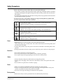
Avoid personal injury and product damage! Do not proceed beyond any symbol until
you fully understand the indicated conditions!
You may find this symbol on the product and/or in the literature that
accompanies this product.
It indicates important operating or maintenance instructions.
You may find this symbol on the product and/or in the literature that
accompanies this product.
It indicates a live terminal; the symbol pointing to the terminal device.
You may find this symbol on the product and/or in the literature that
accompanies this product.
It indicates a protective earth terminal.
You may find this symbol on the product and/or in the literature that
accompanies this product.
It indicates excessive or dangerous heat.
Power
• Important! This is a Class I product. You must earth this product.
This product plugs into a socket-outlet. The socket-outlet must be near this product, and
must be easily accessible.
• Connect this product only to the power source that is indicated on the back panel of this
product.
• If this product does not have a mains power switch, the power cord serves this purpose.
Enclosure
• Do not allow moisture to enter this product.
• Do not open the enclosure of this product unless otherwise specified.
• Do not push objects through openings in the enclosure of this product.
Cables
• Always disconnect all power cables before servicing this product.
• Always pull on the plug or the connector to disconnect a cable. Never pull on the cable
itself.
• Do not walk on or place stress on cables or plugs.
Fuses
• When AC-supplied, the D9032 Encoder has double pole neutral fusing.
• Always use a fuse that has the correct type and rating, and is approved for use by the
country or jurisdiction where this product is installed.
• The correct fuse type and rating are indicated on this product.
Factory service
• Refer service only to service personnel who are authorized by the factory.
4019394 Rev B
v
Règles de sécurité
Protégez-vous des risques d'électrocution et protégez votre système contre les
endommagements éventuels.
• Ce produit respecte les standards internationaux de sécurité et de conception. Veuillez
observer toutes les procédures de sécurité qui apparaissent dans ce guide, ainsi que les
symboles de sécurité qui figurent sur le produit.
• Si, du fait des circonstances, ce produit cesse de fonctionner normalement, cessez de
l'utiliser et empêchez-en l'utilisation future.
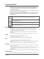
Évitez le risque de blessures et de dommages aux produits! Ne procédez à aucune tâche
tant que vous n'aurez pas entièrement assimilé les conditions indiquées par un symbole!
Ce symbole figure dans la documentation accompagnant ce produit. Il indique
d'importantes instructions de fonctionnement ou d'entretien.
Ce symbole peut être attaché à ce produit. Il indique une borne sous tension; la
direction indique la borne.
Ce symbole peut être attaché à ce produit. Il indique une borne de terre de
protection.
Ce symbole peut être attaché à ce produit. Il indique une température excessive ou
dangereuse.
Alimentation
• Important! Ce produit fait partie de la classe I. Vous devez le mettre à la terre.
• Ce produit se branche dans une prise murale. Cette dernière doit être placée à proximité
du produit et doit être facilement accessible.
• Ne branchez ce produit qu'à la source d'alimentation indiquée sur son panneau arrière.
• Si ce produit n'a pas d'interrupteur d'alimentation générale, le cordon d'alimentation
remplit ce rôle.
Enceinte
• Ne laissez pas l'humidité pénétrer dans ce produit.
• N'ouvrez pas l'enceinte de ce produit, sauf instructions contraires.
• Ne forcez pas d'objets dans les ouvertures du boîtier.
Câbles
• Débranchez toujours tous les cordons d'alimentation avant de réparer ce produit.
• Tirez toujours sur la prise ou le connecteur pour débrancher un câble. Ne tirez jamais
directement sur le câble.
• Ne marchez pas sur les câbles ou les prises et n'y exercez aucune pression.
Fusibles
• Si alimenté par une source, le D9032 Encoder a fondre double pôle/fusible au neutre.
• Veillez à toujours utiliser un fusible de type et de puissance adéquats agréé par le pays ou
la juridiction d'utilisation du présent produit.
• Le type et la puissance des fusibles à utiliser sont indiqués sur le produit.
Réparations effectuées à l'usine
• Ne confiez les travaux de réparations qu'au personnel autorisé par l'usine.
vi
4019394 Rev B
Sicherheitsvorkehrungen
Schützen Sie sich gegen elektrischen Schlag, und Ihr Gerät gegen Beschädigung!
• Dieses Gerät entspricht internationalen Sicherheits-und Ausführungsnormen. Beachten
Sie alle in diesem Handbuch enthaltenen Sicherheitshinweise sowie die am Gerät
angebrachten Warnzeichen.
• Sollten örtliche Umstände den sicheren Betrieb dieses Gerätes beeinträchtigen, schalten
Sie es ab und sichern es gegen weitere Benutzung.
Vermeiden Sie Verletzungen sowie Beschädigung des Gerätes! Wenn Sie zu einem der
folgenden Warnzeichen gelangen, nicht weiterarbeiten, bis Sie seine Bedeutung voll
verstanden haben!
Dieses Symbol erscheint auf dem Gerät und/oder in der ihm beiliegenden Literatur.
Es bedeutet wichtige, zu beachtende Betriebs-oder Wartungsanweisungen.
Wenn dieses Zeichen am Gerät angebracht ist, warnt es vor einer
spannungsführenden Stelle.
Dieses Symbol kennzeichnet auf dem Gerät die Anschlußstelle der Sicherheitserde.
Wenn dieses Zeichen am Gerät angebracht ist, warnt es vor heißen Stellen, die zu
Verbrennungen führen können.
Netzspannung
• Wichtig! Dieses Gerät ist ein Produkt der Schutzklasse I. Es muß geerdet werden.
• Das Gerät ist an einer Steckdose anzuschließen. Diese muß sich leicht zugänglich in
unmittelbarer Nähe des Gerätes befinden.
• Die Netzversorgung muß den auf der Rückwand des Gerätes angegebenen Werten
entsprechen.
• Falls sich kein Hauptschalter am Gerät befindet, dient das Netzkabel diesem Zweck.
Gehäuse
• Das Innere des Gerätes ist vor Feuchtigkeit zu schützen.
• Das Gehäuse ist nicht zu öffnen.
• Niemals einen Gegenstand durch die Gehäuseöffnungen einführen!
Kabel
• Vor jeglicher Wartung des Gerätes sind alle Kabel zu entfernen.
• Hierzu grundsätzlich am Stecker oder Verbindungsstück und niemals am Kabel selber
ziehen.
• Nicht auf die Kabel oder Stecker treten oder diese einer Zugbelastung aussetzen.
Sicherungen
• Wenn mit AC-Speisung versehen, der D9032 Encoder hat zweipolige bzw. Neutralleiter
Sicherung im Netzteil.
• Immer den korrekten Sicherungstyp mit dem richtigen Nennwert benutzen, der im Land
oder innerhalb der zuständigen Gerichtsbarkeit genehmigt ist, wo dieses Produkt
installiert wird.
• Angaben zum korrekten Sicherungstyp und Nennwert befinden sich auf diesem Produkt.
Hersteller-Wartung
Wartungsarbeiten sind nur durch vom Hersteller autorisierte Techniker vorzunehmen.
4019394 Rev B
vii
Precauciones de seguridad
¡Protéjase contra la electrocución y proteja su sistema contra los daños!
• Este producto cumple con los criterios internacionales de seguridad y diseño. Observe
todas los procedimientos de seguridad que aparecen en esta guía, y los símbolos de
seguridad adheridos a este producto.
• Si las circunstancias impiden la operación segura de este producto, suspenda la operación
y asegure este producto para que no siga funcionando.
¡Evite lastimarse y evite dañar el producto! No avance más allá de cualquier símbolo
hasta comprender completamente las condiciones indicadas!
Encontrará este símbolo en el impreso que acompaña a este producto. Este símbolo
indica instrucciones importantes de funcionamiento o mantenimiento.
Es posible que este símbolo esté pegado al producto. Este símbolo indica un terminal
vivo, la flecha apunta hacia el aparato terminal
Podría encontrar este símbolo pegado al producto. Este símbolo indica un terminal
de protección de tierra.
Podría encontrar este símbolo pegado al producto. Este símbolo indica calor
excesivo o peligroso.
Power
• Importante! Este es un producto de Clase I. Tiene que estar conectado a tierra.
• Este producto se conecta a un enchufe. El enchufe necesita estar cerca del producto y ser
fácilmente accesible.
• Conecte este producto únicamente a la fuente de suministro eléctrico indicada en el panel
posterior del producto.
• Si el producto no tiene interruptor para la linea principal, utilice el cordón toma de
corriente para este propósito.
Cubierta
• No permita que la humedad penetre en este producto.
• No abra la cubierta del producto a menos que se indique lo contrario.
• No introduzca objetos a través de las aberturas de la cubierta del producto.
Cables
• Siempre desconectar todos los cables eléctricos antes de revisar o reparar el producto.
• Tire siempre del enchufe o del conector para desconectar un cable. Nunca tire del cable
mismo.
• No camine ni aplique presión sobre los cables o enchufes.
Fusibles
• Cuándo AC había suministrado, el D9032 Encoder tiene doble polo fusible-neutral.
• Use siempre un fusible del tipo y capacidad nominal correctos y que haya sido aprobado
para su uso en el país o jurisdicción en que se instale este producto.
• El tipo y capacidad nominal correctos del fusible se indican en este producto.
Revisión y reparación de fábrica
Solo personal aprobado por la fábrica puede darle servicio al producto.
viii
4019394 Rev B
Precauzioni di sicurezza
Proteggetevi da scosse elettriche e proteggete il vostro sistema da possibili danni!
• Questo prodotto soddisfa le norme internazionali per la sicurezza ed il design. Seguite
tutte le procedure di sicurezza contenute in questa guida e i simboli di sicurezza applicati
al prodotto.
• Se circostanze avverse compromettono la sicurezza d'uso di questo prodotto,
interrompetene l'uso e assicuratevi che il prodotto non venga più utilizzato.
Evitare infortuni alla persona e danni al prodotto! Non procedere oltre a qualunque
simbolo fino a quando non si siano comprese pienamente le condizioni indicate!
Questo simbolo, che appare nella letteratura di accompagnamento del prodotto,
indica importanti istruzioni d'uso e di manutenzione.
Sul prodotto potete vedere questo simbolo che indica un dispositivo terminale sotto
tensione; la freccia punta verso il dispositivo.
Potrete trovare il presente simbolo applicato a questo prodotto. Questo simbolo
indica un terminale protettivo di messa a terra.
Potrete trovare il presente simbolo attaccato a questo prodotto. Questo simbolo
indica un calore eccessivo o pericoloso.
Alimentazione
• Importante! Questo prodotto è di Classe I. Va messo a terra.
• Questo prodotto si inserisce in una presa di corrente. La presa di corrente deve essere in
prossimità del prodotto, e deve essere facilmente accessibile.
• Collegare questo prodotto solamente alla fonte di alimentazione indicata sul pannello
posteriore di questo prodotto.
• Se questo prodotto non è dotato di un interruttore principale, il cavo di alimentazione
funge a questo scopo.
Chiusura
• Proteggete da umidità questo prodotto.
• Non aprire la chiusura di questo prodotto a meno che non sia specificato diversamente.
Non inserire oggetti attraverso le fessure della chiusura.
Cavi
• Staccare sempre tutti i cavi di alimentazione prima di svolgere l'assistenza tecnica al
prodotto.
• Per scollegare un cavo tirate la spina o il connettore, non tirare mai il cavo stesso.
• Non calpestare o sottoporre a sollecitazioni i cavi o le prese.
Fusibili
• Se AC fornito, il D9032 Encoder contiene fusibili su fasi/neutro.
• Utilizzare sempre un fusibile che abbia il tipo e la potenza corretti e che sia autorizzato
all’uso nel paese o nella giurisdizione nella quale il prodotto è installato.
• Il tipo e la potenza corretti sono indicati sul prodotto.
Riparazionoi di fabbrica
• Per le riparazioni contattate solamente personale tecnico autoizzato dalla fabbrica.
4019394 Rev B
ix
Important Safety Instructions
Read and Retain Instructions
Carefully read all safety and operating instructions before operating this equipment, and
retain them for future reference.
Follow Instructions and Heed Warnings
Follow all operating and use instructions. Pay attention to all warnings and cautions in the
operating instructions, as well as those that are affixed to this equipment.
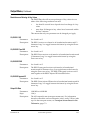
Terminology
The terms defined below are used in this document. The definitions given are based on
those found in safety standards.
Service Personnel - The term service personnel applies to trained and qualified individuals
who are allowed to install, replace, or service electrical equipment. The service personnel
are expected to use their experience and technical skills to avoid possible injury to
themselves and others due to hazards that exist in service and restricted access areas.
User and Operator - The terms user and operator apply to persons other than service
personnel.
Ground(ing) and Earth(ing) - The terms ground(ing) and earth(ing) are synonymous. This
document uses ground(ing) for clarity, but it can be interpreted as having the same meaning
as earth(ing).
Electric Shock Hazard
This equipment meets applicable safety standards.
WARNING:
To reduce risk of electric shock, perform only the instructions that are included in the
operating instructions. Refer all servicing to qualified service personnel only.
Electric shock can cause personal injury or even death. Avoid direct contact with dangerous
voltages at all times. The protective ground connection is essential to safe operation and
must be verified before connecting the power supply.
Know the following safety warnings and guidelines:
• Dangerous Voltages
- Only qualified service personnel are allowed to perform equipment installation or
replacement.
- Only qualified service personnel are allowed to remove chassis covers and access any
of the components inside the chassis.
• Grounding
- Do not violate the protective grounding by using an extension cable, power cable, or
autotransformer without a protective ground conductor.
- Take care to maintain the protective grounding of this equipment during service or
repair and to re-establish the protective grounding before putting this equipment back
into operation.
x
4019394 Rev B
Important Safety Instructions, Continued
Installation Site
When selecting the installation site, comply with the following:
• Protective Ground - The protective ground lead of the building's electrical installation
should comply with national and local requirements.
• Environmental Condition - The installation site should be dry, clean, and ventilated. Do
not use this equipment where it could be at risk of contact with water. Ensure that this
equipment is operated in an environment that meets the requirements as stated in this
equipment's technical specifications, which may be found on this equipment's data sheet.
Installation Requirements
WARNING:
Allow only qualified service personnel to install this equipment.
The installation must conform to all local codes and regulations.
Equipment Placement
WARNING:
Avoid personal injury and damage to this equipment. An unstable mounting surface
may cause this equipment to fall.
To protect against equipment damage or injury to personnel, comply with the following:
• Install this equipment in a restricted access location.
• Do not install near any heat sources such as radiators, heat registers, stoves, or other
equipment (including amplifiers) that produce heat.
• Place this equipment close enough to a mains AC outlet to accommodate the length of
this equipment's power cord.
• Route all power cords so that people cannot walk on, place objects on, or lean objects
against them. This may pinch or damage the power cords. Pay particular attention to
power cords at plugs, outlets, and the points where the power cords exit this equipment.
• Use only with a cart, stand, tripod, bracket, or table specified by the manufacturer, or sold
with this equipment.
• Make sure the mounting surface or rack is stable and can support the size and weight of
this equipment.
• The mounting surface or rack should be appropriately anchored according to
manufacturer's specifications. Ensure this equipment is securely fastened to the mounting
surface or rack where necessary to protect against damage due to any disturbance and
subsequent fall.
Ventilation
This equipment has openings for ventilation to protect it from overheating. To ensure
equipment reliability and safe operation, do not block or cover any of the ventilation
openings. Install the equipment in accordance with the manufacturer's instructions.
4019394 Rev B
xi
Important Safety Instructions, Continued
Rack Mounting Safety Precautions
Mechanical Loading
Make sure that the rack is placed on a stable surface. If the rack has stabilizing devices,
install these stabilizing devices before mounting any equipment in the rack.
WARNING:
Avoid personal injury and damage to this equipment. Mounting this equipment in the
rack should be such that a hazardous condition is not caused due to uneven mechanical
loading.
Reduced Airflow
When mounting this equipment in the rack, do not obstruct the cooling airflow through the
rack. Be sure to mount the blanking plates to cover unused rack space. Additional
components such as combiners and net strips should be mounted at the back of the rack, so
that the free airflow is not restricted.
CAUTION:
Installation of this equipment in a rack should be such that the amount of airflow
required for safe operation of this equipment is not compromised.
Elevated Operating Ambient Temperature
Only install this equipment in a humidity- and temperature-controlled environment that
meets the requirements given in this equipment's technical specifications.
CAUTION:
If installed in a closed or multi-unit rack assembly, the operating ambient temperature
of the rack environment may be greater than room ambient temperature. Therefore,
install this equipment in an environment compatible with the manufacturer's
maximum rated ambient temperature.
Handling Precautions
When moving a cart that contains this equipment, check for any of the following possible
hazards:
WARNING:
Avoid personal injury and damage to this equipment! Move any
equipment and cart combination with care. Quick stops, excessive force,
and uneven surfaces may cause this equipment and cart to overturn.
• Use caution when moving this equipment/cart combination to avoid injury from tipover.
• If the cart does not move easily, this condition may indicate obstructions or cables that
may need to be disconnected before moving this equipment to another location.
• Avoid quick stops and starts when moving the cart.
• Check for uneven floor surfaces such as cracks or cables and cords.
xii
4019394 Rev B
Important Safety Instructions, Continued
Grounding
This section provides instructions for verifying that the equipment is properly grounded.
Safety Plugs (USA Only)
Depending on the type and application of this equipment (Safety Class I or Safety Class II),
Scientific Atlanta supplies a mains cord with either a 3-terminal (grounding-type) safety
plug or a 2-terminal (polarized) safety plug. The wide blade or the third terminal is
provided for safety. Do not defeat the safety purpose of the grounding-type or polarized
safety plug.
To properly ground this equipment, follow these safety guidelines:
• Grounding-Type Plug - For a 3-terminal plug (one terminal on this plug is a protective
grounding pin), insert the plug into a grounded mains, 3-terminal outlet.
Note: This plug fits only one way. If this plug cannot be fully inserted into the outlet,
contact an electrician to replace the obsolete 3-terminal outlet.
• Polarized Plug - For a 2-terminal plug (a polarized plug with one wide blade and one
narrow blade), insert the plug into a polarized mains, 2-terminal outlet in which one
socket is wider than the other.
Note: If this plug cannot be fully inserted into the outlet, try reversing the plug. If the
plug still fails to fit, contact an electrician to replace the obsolete 2-terminal outlet.
Grounding Terminal
If this equipment is equipped with an external grounding terminal, attach one end of an 18gauge wire (or larger) to the grounding terminal; then, attach the other end of the wire to a
ground, such as a grounded equipment rack.
Safety Plugs (European Union)
• Class I Mains Powered Equipment - Provided with a 3-terminal AC inlet and requires
connection to a 3-terminal mains supply outlet via a 3-terminal power cord for proper
connection to the protective ground.
Note: The equipotential bonding terminal provided on some equipment is not designed
to function as a protective ground connection.
• Class II Mains Powered Equipment - Provided with a 2-terminal AC inlet that may be
connected by a 2-terminal power cord to the mains supply outlet. No connection to the
protective ground is required as this class of equipment is provided with double or
reinforced and/or supplementary insulation in addition to the basic insulation provided
in Class I equipment.
Note: Class II equipment, which is subject to EN 50083-1, is provided with a chassis
mounted equipotential bonding terminal. See the section titled Equipotential Bonding
for connection instructions.
Equipotential Bonding
If this equipment is equipped with an external chassis terminal marked with the IEC 604175020 chassis icon (
), the installer should refer to CENELEC standard EN 50083-1 or IEC
standard IEC 60728-11 for correct equipotential bonding connection instructions.
4019394 Rev B
xiii
Important Safety Instructions, Continued
AC Power
Important: If this equipment is a Class I equipment, it must be grounded.
• If this equipment plugs into an outlet, the outlet must be near this equipment, and must
be easily accessible.
• Connect this equipment only to the power sources that are identified on the equipmentrating label normally located close to the power inlet connector(s).
• If this equipment has two power sources be sure to disconnect all power sources before
working on this equipment.
• If this equipment does not have a main power switch, the power cord connector serves as
the disconnect device.
• Always pull on the plug or the connector to disconnect a cable. Never pull on the cable
itself.
• Unplug this equipment when unused for long periods of time.
Connection to -48 V DC/-60 V DC Power Sources
If this equipment is DC powered, refer to the specific installation instructions in this
manual or in companion manuals in this series for information on connecting this
equipment to nominal -48 V DC/-60 V DC power sources.
Circuit Overload
Know the effects of circuit overloading before connecting this equipment to the power
supply.
CAUTION:
Consider the connection of this equipment to the supply circuit and the effect that
overloading of circuits might have on overcurrent protection and supply wiring. Refer
to the information on the equipment-rating label when addressing this concern.
General Servicing Precautions
WARNING:
Avoid electric shock! Opening or removing this equipment's cover may expose you to
dangerous voltages.
Be aware of the following general precautions and guidelines:
• Servicing - Refer all servicing to qualified service personnel. Servicing is required when
this equipment has been damaged in any way, such as power supply cord or plug is
damaged, liquid has been spilled or objects have fallen into this equipment, this
equipment has been exposed to rain or moisture, does not operate normally, or has been
dropped.
xiv
4019394 Rev B
Important Safety Instructions, Continued
• Wristwatch and Jewelry - For personal safety and to avoid damage of this equipment
during service and repair, do not wear electrically conducting objects such as a
wristwatch or jewelry.
• Lightning - Do not work on this equipment, or connect or disconnect cables, during
periods of lightning.
• Labels - Do not remove any warning labels. Replace damaged or illegible warning labels
with new ones.
• Covers - Do not open the cover of this equipment and attempt service unless instructed to
do so in the instructions. Refer all servicing to qualified service personnel only.
• Moisture - Do not allow moisture to enter this equipment.
• Cleaning - Use a damp cloth for cleaning.
• Safety Checks - After service, assemble this equipment and perform safety checks to
ensure it is safe to use before putting it back into operation.
Electrostatic Discharge
Electrostatic discharge (ESD) results from the static electricity buildup on the human body
and other objects. This static discharge can degrade components and cause failures.
Take the following precautions against electrostatic discharge:
• Use an anti-static bench mat and a wrist strap or ankle strap designed to safely ground
ESD potentials through a resistive element.
• Keep components in their anti-static packaging until installed.
• Avoid touching electronic components when installing a module.
Fuse Replacement
To replace a fuse, comply with the following:
• Disconnect the power before changing fuses.
• Identify and clear the condition that caused the original fuse failure.
• Always use a fuse of the correct type and rating. The correct type and rating are indicated
on this equipment.
Lithium Battery
For equipment with a lithium battery, observe the following rules:
• Do not dispose of used batteries through the regular garbage collection system, but follow
the local regulations. The batteries may contain substances that could be harmful to the
environment.
• Replace batteries with the same or equivalent type recommended by Scientific Atlanta.
• Insert batteries correctly. There may be a risk of explosion if the batteries are incorrectly
inserted.
• When disposing of this equipment, remove the batteries and dispose of them separately
in accordance with local regulations.
• Do not recharge the batteries or expose them to temperatures above 100°C (212°F).
Electromagnetic Compatibility Regulatory Requirements
This equipment meets applicable electromagnetic compatibility (EMC) regulatory
requirements. EMC performance is dependent upon the use of correctly shielded cables of
good quality for all external connections, except the power source, when installing this
equipment.
• Ensure compliance with cable/connector specifications and associated installation
instructions where given elsewhere in this manual.
4019394 Rev B
xv
Important Safety Instructions, Continued
Otherwise, comply with the following good practices:
• Multi-conductor cables should be of single-braided, shielded type and have conductive
connector bodies and backshells with cable clamps that are conductively bonded to the
backshell and capable of making 360° connection to the cable shielding. Exceptions from
this general rule will be clearly stated in the connector description for the excepted
connector in question.
• Ethernet cables should be of single-shielded or double-shielded type.
• Coaxial cables should be of the double-braided shielded type.
EMC
Where this equipment is subject to USA FCC and/or Industry Canada rules, the following
statements apply:
FCC Statement
This equipment has been tested and found to comply with the limits for a Class A digital
device according to Part 15 of FCC Rules. These limits are designed to provide reasonable
protection against harmful interference when this equipment is operated in a commercial
environment.
This equipment generates, uses, and can radiate radio frequency energy and, if not installed
and used in accordance with the instruction manual, may cause harmful interference to
radio communications. Operation of this equipment in a residential area is likely to cause
harmful interference in which case the user will be required to correct the interference at his
own expense.
Industry Canada - Industrie Canadienne Statement
Industry Canada ICES-003: This Class A digital apparatus meets all the requirements of the
Canadian Interference-Causing Equipment Regulations.
Industrie Canadienne ICES-003: Cet appareil numèrique de la Class A respecte toutes les
exigences du Règlement sur le matèriel brouilleur du Canada.
CENELEC/CISPR Statement with Respect to Class A Information Technology Equipment
This is a Class A equipment. In a domestic environment this equipment may cause radio
interference in which case the user may be required to take adequate measures.
Modifications
This equipment has been designed and tested to comply with applicable safety, laser safety,
and EMC regulations, codes, and standards to ensure safe operation in its intended
environment. Refer to this equipment's data sheet for details about regulatory compliance
approvals.
Do not make modifications to this equipment. Any changes or modifications could void the
user's authority to operate this equipment.
Modifications have the potential to degrade the level of protection built into this equipment,
putting people and property at risk of injury or damage. Those persons making any
modifications expose themselves to the penalties arising from proven non-compliance with
regulatory requirements and to civil litigation for compensation in respect of consequential
damages or injury.
Accessories
Use only attachments or accessories specified by the manufacturer.
xvi
4019394 Rev B
Compliance
Electromagnetic Compatibility
FCC Part 15 Subpart B: This equipment has been tested and found to comply with the limits
for a Class A digital device, pursuant to Part 15 of the FCC Rules.
CE marked: according to EMC directive 89/336/EEC and 93/68/EEC
(European standards EN 55 022, EN 55 024, EN 61000-3-2 and EN 61000-3-3).
C-Tick marked: according to AS/NZS CISPR 22/2002.
Safety
UL listed: according to UL60950.
cUL listed: according to CSA C22.2 no. 60950.
CE marked: according to LVD directive 73/23/EEC and 93/68/EEC
(European standard EN 60950).
CB certification: according to IEC 60950.
4019394 Rev B
xvii
Warranty and Disclaimer
The terms "we", "us", and "our" are used to refer to Scientific-Atlanta, Inc. The term
"Item" is used to refer to our products (including software) provided hereunder. We
make no representations that our product is fully compatible with similarly
represented equipment from other vendors due to the wide range of
implementation possibilities of the applicable standards. We extend the following
warranty coverage to the original purchaser only, hereafter referred to as
"Purchaser". Items must be purchased from an authorized Scientific Atlanta
representative or distributor.
We warrant good title to any hardware Item furnished hereunder. During the
Warranty Period (as defined below) we warrant that any hardware Item
manufactured by or for us will be free from material defects in workmanship and
materials and under ordinary use, conform in all material respects to its published
specifications current at the time the hardware Item was shipped. For a software
Item licensed by us, we warrant that we have the right to grant any software Item
license granted and that the software Item, as provided, shall substantially conform
to its published specifications current at the time the software Item was shipped.
Separately branded hardware and software Items ("Third-Party Products") are
warranted solely by the applicable manufacturer or licensor as provided below. We
will repair or replace, at our option, any Item (excluding Third-Party Products)
returned to us by Purchaser at its expense during the Warranty Period, which fails
to satisfy this Warranty, unless the failure was the result of shipping; improper
installation, maintenance or use; abnormal conditions of operation; attempted
modification or repair by the Purchaser; use of the Items in combination with other
items; or an act of God. If we elect to replace an Item, any duties, taxes, or expenses
related to the importation of the replacement Item shall be at Purchaser's expense.
The Warranty Period begins on the date the Item is originally delivered and extends
for (a) twelve (12) months for a new hardware Item manufactured by or for us, (b)
six (6) months for a remanufactured hardware Item that has been reworked by us
and is designated by us with "RMF" in the part number, and (c) ninety (90) days for
a software Item licensed by us and for parts. For Third-Party Products, we will pass
through, to the extent permitted, the manufacturer's and/or licensor's warranties
and Purchaser shall look solely to such manufacturer and/or licensor for warranty
repair. For any hardware Item that is returned to us during the Warranty Period
and which is repaired or replaced by us, the Warranty Period for such repaired or
replaced hardware Item shall be the longer of (i) the remainder of the Warranty
Period for the hardware Item, or (ii) ninety (90) days after repair or replacement of
such hardware Item by us.
xviii
4019394 Rev B
Warranty and Disclaimer, Continued
THIS WARRANTY IS IN LIEU OF ALL OTHER WARRANTIES, EXPRESS,
IMPLIED OR STATUTORY, INCLUDING ANY WARRANTY OF
MERCHANTABILITY, FITNESS FOR A PARTICULAR PURPOSE OR
NONINFRINGEMENT. PURCHASER'S SOLE REMEDY FOR ANY BREACH OF
WARRANTY FOR HARDWARE ITEMS MANUFACTURED BY OR FOR US AND
SOFTWARE ITEMS LICENSED BY US IS THE REPAIR OR REPLACEMENT, AT
OUR OPTION, OF THE FAILED ITEM. PURCHASER'S SOLE REMEDY FOR ANY
BREACH OF WARRANTY FOR A THIRD-PARTY PRODUCT IS THE
MANUFACTURER'S WARRANTY FOR SUCH PRODUCT. WE SPECIFICALLY
DISCLAIM ANY AND ALL WARRANTIES, EXPRESS OR IMPLIED, TO
CUSTOMERS OF PURCHASER, AND ANY AND ALL WARRANTIES WITH
RESPECT TO THIRD-PARTY PRODUCTS. WE MAKE NO WARRANTY THAT
THE OPERATION OF ANY SOFTWARE ITEM WILL BE UNINTERRUPTED OR
ERROR FREE. IN ADDITION, DUE TO THE CONTINUAL DEVELOPMENT OF
NEW TECHNIQUES FOR INTRUDING UPON AND ATTACKING NETWORKS,
WE DO NOT WARRANT THAT ANY SOFTWARE ITEM OR ANY HARDWARE
ITEM ON WHICH THE SOFTWARE ITEM IS USED WILL BE FREE FROM
VULNERABILITY TO INTRUSION OR ATTACK.
EXCEPT FOR CLAIMS FOR PERSONAL INJURY CAUSED BY ITEMS OR
SERVICES FURNISHED HEREUNDER, WE SHALL NOT BE LIABLE TO
PURCHASER OR ANY OTHER PERSON OR ENTITY FOR INDIRECT, SPECIAL,
INCIDENTAL, CONSEQUENTIAL, PUNITIVE, OR EXEMPLARY DAMAGES OR
LOSS OF PROFITS ARISING OUT OF OR IN CONNECTION WITH THIS
TRANSACTION OR ANY ACTS OR OMISSIONS ASSOCIATED THEREWITH OR
RELATING TO THE SALE, LICENSE OR USE OF ANY ITEMS FURNISHED,
WHETHER SUCH CLAIM IS BASED ON BREACH OF WARRANTY,
CONTRACT, TORT OR OTHER LEGAL THEORY AND REGARDLESS OF THE
CAUSES OF SUCH LOSS OR DAMAGES, WHETHER WE WERE AWARE OF THE
POSSIBILITY OF SUCH DAMAGES, OR WHETHER ANY OTHER REMEDY
PROVIDED HEREIN FAILS. IN NO EVENT SHALL OUR TOTAL LIABILITY
HEREUNDER EXCEED AN AMOUNT EQUAL TO THE TOTAL AMOUNT PAID
FOR ITEMS PURCHASED HEREUNDER. IN NO EVENT SHALL WE BE LIABLE
TO PURCHASER FOR ANY DAMAGES RELATED TO A LICENSED SOFTWARE
ITEM IN EXCESS OF THE LESSER OF TEN THOUSAND UNITED STATES
DOLLARS (US$10,000) OR THE LICENSE FEE PAID BY PURCHASER TO US FOR
THE LICENSED SOFTWARE ITEM.
If the Purchaser returns an Item to us that is not defective under the Warranty or for
which the Warranty Period has expired, we will perform diagnostic tests on the
Item and repair the Item if it is defective. In such instances, we will be entitled to
charge the Purchaser reasonable charges for such diagnostic testing and/or repair
work.
4019394 Rev B
xix
xx
4019394 Rev B
Contents
Safety Precautions .......................................................................................................................................v
Règles de sécurité .......................................................................................................................................vi
Sicherheitsvorkehrungen ..........................................................................................................................vii
Precauciones de seguridad ..................................................................................................................... viii
Precauzioni di sicurezza .............................................................................................................................ix
Important Safety Instructions...................................................................................................................... x
Compliance .............................................................................................................................................. xvii
Warranty and Disclaimer ....................................................................................................................... xviii
About This Manual ................................................................................................................................ xxvii
Chapter 1
Quick Setup - Read Me First!
Connecting the Units ........................................................................................................1-1
Front Panel Setup ..............................................................................................................1-3
Setting up the D9032 Encoders from ROSA or Via the Web Interface......................1-4
Chapter 2
Introduction
Overview............................................................................................................................2-1
Encoder Model D9032 ......................................................................................................2-2
Application Examples ......................................................................................................2-6
Video Interfaces.................................................................................................................2-8
Audio and Data Interfaces...............................................................................................2-9
Transport Stream Outputs .............................................................................................2-11
Control and Management Interfaces............................................................................2-12
0
Chapter 3
Installation
Overview............................................................................................................................3-1
0
Section A - Rack Installation .................................................................................................3-3
General................................................................................................................................3-3
Installing the D9032 Encoder ..........................................................................................3-4
Connection of Scientific Atlanta Equipment to DC Power Sources ..........................3-5
Section B - Connector Panel.................................................................................................3-9
Overview ............................................................................................................................3-9
4019394 Rev B
xxi
Contents, Continued
Section C - Connecting the Input/Output Signals ................................................................3-11
Connecting the Video and Reference Signal Inputs ..................................................3-11
Connecting the Audio Inputs........................................................................................3-12
Connecting to the Contact Closure or Cue Tone Interfaces......................................3-16
Connecting the Statmux Interface ................................................................................3-17
Connecting an External Alarm System........................................................................3-18
Connecting the Ethernet Management Interface........................................................3-19
Connecting the ASI Outputs and the ASI Monitor Decoder ....................................3-20
Connecting the IP TS Output ........................................................................................3-21
Connecting the Aux Output ..........................................................................................3-22
Chapter 4
Front Panel Operation
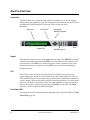
Overview............................................................................................................................4-1
About the Front Panel ......................................................................................................4-2
Keypad Convention..........................................................................................................4-4
Startup Screen....................................................................................................................4-5
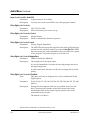
Main Menu.........................................................................................................................4-6
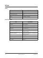
PSI Menu ............................................................................................................................4-7
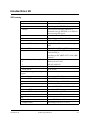
Video Menu .......................................................................................................................4-9
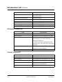
Audio Menu.....................................................................................................................4-16
Output Menu ...................................................................................................................4-22
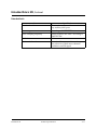
System Menu ...................................................................................................................4-25
Lock Menu .......................................................................................................................4-34
0
Chapter 5
Setup and Monitoring
Overview............................................................................................................................5-1
0
Section A - Getting started with ROSA ..................................................................................5-6
Installing ROSA and Drivers...........................................................................................5-6
Installing the D9032 Encoder Device Driver.................................................................5-7
Setting Up the Search Range for the D9032 Encoder Agent .......................................5-9
Assigning the D9032 Encoder Agent as a Unit in ROSA ..........................................5-11
Working With the User Interface in ROSA .................................................................5-13
Section B - The Web Interface .............................................................................................5-14
Before You Begin.............................................................................................................5-14
Logging On to the Web Interface..................................................................................5-15
Creating a Logon Password ..........................................................................................5-16
Web Interface - Summary Screen..................................................................................5-17
Tab Pages..........................................................................................................................5-18
The Menu Bar and Buttons ............................................................................................5-19
xxii
4019394 Rev B
Contents, Continued
Context-Sensitive Online Help......................................................................................5-20
Section C - TS Rate Budget .................................................................................................5-21
Making a TS Rate Budget...............................................................................................5-21
Section D - Setting Up the Video .........................................................................................5-22
Setting Up the Video Input............................................................................................5-22
Setting Up the Video Encoder.......................................................................................5-24
Setting Up the Video Encoder Delays..........................................................................5-27
Reduced Delay Guidelines ............................................................................................5-29
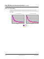
Delay, Bit Rate and Consecutive B-pictures................................................................5-31
Setting Up the Video Encoder Aspect Ratio ...............................................................5-33
Setting Up the Video Encoder Rate ..............................................................................5-35
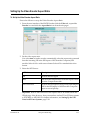
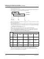
Setting Up the Statistical Multiplexing ........................................................................5-38
Determining the Default Video Rate............................................................................5-43
Setting Up the Stand-Alone Variable Bit Rate ............................................................5-45
Section E - Setting Up the Pre-Processor ............................................................................5-47
Setting Up the Pre-Processor Parameters ....................................................................5-47
3:2 Pulldown and 3:2 Pulldown Inversion ..................................................................5-52
Section F - Setting Up the Audio .........................................................................................5-54
Enabling or Disabling the Audio Channels ................................................................5-54
Setting Up the Layer II Audio Input ............................................................................5-55
Setting Up the Layer II Channel Information .............................................................5-58
Setting Up the Layer II Processing ...............................................................................5-59
Setting Up the Layer II Test Tones ...............................................................................5-60
Setting Up the Dolby Digital Audio Input ..................................................................5-62
Setting Up the Dolby Digital Processing .....................................................................5-66
Setting Up the Dolby Digital Channels........................................................................5-68
Setting Up the Dolby Digital Passthrough ..................................................................5-70
Setting Up the Dolby Digital Test Tones .....................................................................5-71
Setting Up the Linear/Dolby E Audio Input..............................................................5-73
Setting Up the Linear/Dolby E Processing .................................................................5-75
Setting Up the Linear/Dolby E Linear Parameters....................................................5-76
Section G - Setting Up the VBI.............................................................................................5-77
Selecting VBI Source and Enabling VBI Resources....................................................5-77
Setting Up the VBI Lines in 625 Lines Systems ..........................................................5-81
Setting Up the VBI Lines in 525 Lines Systems ..........................................................5-83
Setting Up the Teletext ...................................................................................................5-84
Setting Up the Output Formats for Closed Captions ................................................5-86
4019394 Rev B
xxiii
Contents, Continued
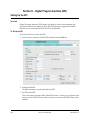
Section H - Digital Program Insertion (DPI).........................................................................5-88
Setting Up the DPI ..........................................................................................................5-88
Section I - Setting Up the TS Output ....................................................................................5-91
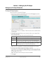
Setting Up the TS Output Parameters..........................................................................5-91
Setting Up the ASI Output Parameters........................................................................5-92
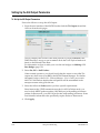
Setting Up the IP Streaming Parameters .....................................................................5-93
Streaming Video to Many Set-top Boxes (Multicasting) ...........................................5-97
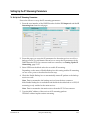
Setting Up the PCR Synchronization ...........................................................................5-99
Setting Up the Conditional Access Parameters ........................................................5-101
Section J - Setting Up the PSI............................................................................................5-103
Enabling/Disabling the PSI/SI Information.............................................................5-103
Setting Up the Transport Stream ................................................................................5-104
Setting Up the Video Program ....................................................................................5-105
Defining the Audio-only Programs............................................................................5-106
Setting Up the Layer II Audio Program ....................................................................5-107
Selecting the Dolby Digital Audio Descriptor Mode...............................................5-109
Click Apply.Setting Up the Dolby Digital Audio Program....................................5-110
Setting Up the Linear Audio Program.......................................................................5-112
Setting Up the VBI PIDs and the Teletext Descriptor Table ...................................5-114
Setting Up the NIT ........................................................................................................5-117
Setting Up the Cable NIT.............................................................................................5-118
Setting Up the Satellite NIT .........................................................................................5-119
Setting Up the Terrestrial NIT.....................................................................................5-120
Section K - Working with the System ................................................................................5-121
Reading the System Information or Managing the System ....................................5-121
Reading the Encoder Temperatures...........................................................................5-123
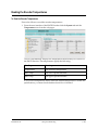
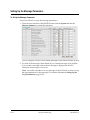
Setting Up the Message Parameters ...........................................................................5-124
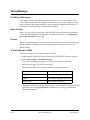
Viewing Messages.........................................................................................................5-126
Viewing the Message Log............................................................................................5-127
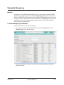
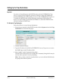
Setting Up the Trap Destinations................................................................................5-128
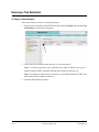
Removing a Trap Destination .....................................................................................5-130
Reading the Module Information ...............................................................................5-131
Setting the Date and Time Manually .........................................................................5-132
Setting the Clock Synchronization .............................................................................5-133
Installing and Enabling Software Options ................................................................5-135
Setting Up the IP Networking.....................................................................................5-137
xxiv
4019394 Rev B
Contents, Continued
Chapter 6
Service and Maintenance
Overview............................................................................................................................6-1
0
Section A - Replacing Fans and Fuses ..................................................................................6-2
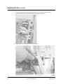
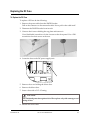
Introduction .......................................................................................................................6-2
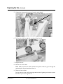
Replacing the Fan..............................................................................................................6-3
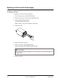
Replacing an AC Fuse in the Power Supply .................................................................6-6
Replacing the DC Fuse .....................................................................................................6-7
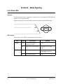
Section B - Status Signaling.................................................................................................6-8
Front Panel LEDs ..............................................................................................................6-8
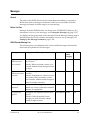
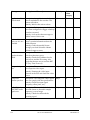
Messages.............................................................................................................................6-9
Chapter 7
Customer Information
Overview............................................................................................................................7-1
Product Support ................................................................................................................7-2
Returning Products...........................................................................................................7-4
0
Appendix A Technical Specifications
Overview...........................................................................................................................A-1
0
Section A - Video Input and Processing ...............................................................................A-2
MPEG-2 Encoder Specifications.....................................................................................A-2
Composite Video Input ...................................................................................................A-3
VBI Specifications in Composite Video ........................................................................A-6
SDI Input ...........................................................................................................................A-8
Embedded Data in SDI....................................................................................................A-9
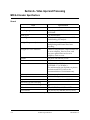
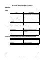
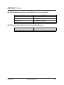
Section B - Audio Input and Processing .............................................................................A-12
Audio Input ....................................................................................................................A-12
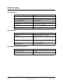
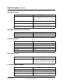
Audio Processing ...........................................................................................................A-14
Section C - Data Interfaces .................................................................................................A-16
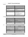
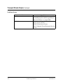
Section D - Transport Stream Output .................................................................................A-17
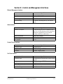
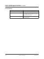
Section E - Control and Management Interfaces.................................................................A-19
Section F - Power and General Specifications ....................................................................A-21
Power ...............................................................................................................................A-21
General.............................................................................................................................A-22
Appendix B Pre-processing
Overview........................................................................................................................... B-1
Overview ........................................................................................................................... B-2
0
4019394 Rev B
xxv
Contents, Continued
Delay and Filters .............................................................................................................. B-4
Appendix C Transport Stream Rates
Overview...........................................................................................................................C-1
Introduction ......................................................................................................................C-2
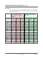
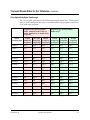
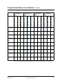
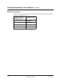
Transport Stream Rates for the Tributaries..................................................................C-3
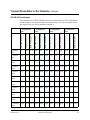
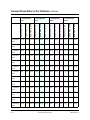
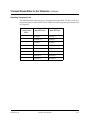
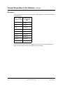
Available Rate on the Transmission Media ...............................................................C-16
0
Appendix D ISO 639-2 Language Codes
Overview...........................................................................................................................D-1
Language Codes - Sorted by Alpha 3-Letter Code (ISO 639-2).................................D-2
0
Appendix E SNMP Quick Setup Guide
Overview........................................................................................................................... E-1
Introduction ...................................................................................................................... E-2
SNMP Managers .............................................................................................................. E-4
SNMP Hints and Common Pitfalls ............................................................................... E-5
0
Appendix F Equipment and Accessories
Overview............................................................................................................................F-1
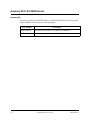
Accessory Kit for the D9032 Encoder.............................................................................F-2
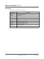
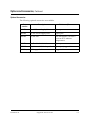
Options and Accessories ..................................................................................................F-3
0
Appendix G References
Applicable Documents ....................................................................................................G-1
Glossary ....................................................................................................................................... Glossary-1
Index .................................................................................................................................................. Index-1
xxvi
4019394 Rev B
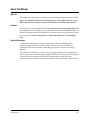
About This Manual
Objective
This manual describes how to install, use and maintain the Encoder Model D9032.
Note: The manual describes all available options for the D9032 Encoder. Your
D9032 Encoder may only have some of the features described in this manual.
Audience
The audience of this manual includes users (operators) and service personnel who
are responsible for the installation, operation and service of the D9032 Encoder. For
further information about the definition of operator and service personnel, see also
the section about Service Personnel and Users and Operators in Terminology,
page x.
Required Knowledge
To use this documentation, the user should have a basic knowledge of the
technology used in relation to this product. Service personnel should have
additional skills and be familiar with cabling, electronic circuitry, and wiring
practices.
This manual is intended for operators who are responsible for the configuration,
remote operation and maintenance of the D9032 Encoder. The operator is required
to have a basic knowledge of the ROSA™ management system but is not
necessarily familiar with tasks, task relationships, task commands or other drivers.
4019394 Rev B
xxvii
About This Manual, Continued
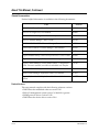
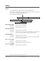
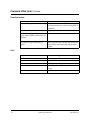
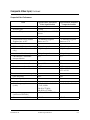
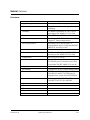
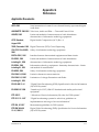
Related Documentation
Further helpful information is available in the following documents:
Title
Part No.
ROSA™ 3.0 Client, User Manual
6984888
ROSA™ 3.0 Single User, User Manual
6984882
ROSA™ Element Manager Installation and Operation Guide
4006813
ROSA™ Element Manager - User's Guide
4005743
COPERNICUS™ MKIII - Element Manager, User manual
6985110
COPERNICUS MKIII - Element Manager - User Manual
6985110
COPERNICUS MKIV User's Guide
4005590
Digital Headend Backup, Task Driver for ROSA 3.0, User’s Guide 6985066
Digital Content Manager (DCM) Model D9900 – System Guide
4011745
Digital Content Manager (DCM) Model D9900 – Configuration
Guide. Electronic manual, accessible via embedded user interface
4011746
COPERNICUS MKIV System G4 User's Guide
4010960
Multi Encoder Manager, Application Layer, User manual
4013152
Regulus™, Statistical Multiplex Controller User and Service
manual
4006277
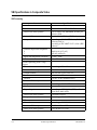
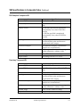
Product Versions
This user manual complies with the following software versions:
• D9032 Encoder embedded software version 2.10
• ROSA™ management system version 3.0 build 8 or greater
• SNMP protocol driver version 3.0.20
• D9032 Encoder device driver version 3.0.4
xxviii
4019394 Rev B
Chapter 1
Quick Setup - Read Me First!
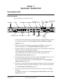
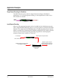
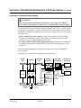
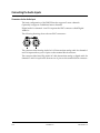
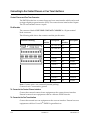
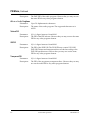
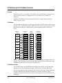
Connecting the Units
Electrical Connection
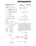
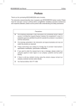
Proceed as follows to connect the units:
AC Power
Ref In
Composite Input
IP TS Out
ASI Monitor Management Backup SDI In
ASI Output 1 +2
Alarm
Statmux
IP TS Out
Main
Cue Contact Analog Audio
Tone Closure In, 1 + 2
Digital
Analog/Digital
Audio In
04-032
1. Connect the video input signal to the SDI IN and/or COMPOSITE IN connector.
For further information, see Connecting the Video and Reference Signal
Inputs, page 3-11.
2. If relevant, connect the reference input signal to the REF IN connector. For
further information, see To Connect the Reference Input, page 3-11.
3. Connect the audio input signals for channels 1 and 2 to the DIGITAL AUDIO IN
(2 BNC connectors) or Analog Audio IN 1&2.
Use a high-quality shielded balanced audio cable for the analog inputs or a
single-ended cable for the digital inputs. For further information, see
Connecting the Audio Inputs, page 3-12.
4. Connect the statmux interface connector of each of the D9032 Encoders to one of
the 16 statmux channel connectors of the Regulus Controller.
Use a one-to-one RS-232 cable. For further information, see Connecting the
Statmux Interface, page 3-17.
5. If relevant, connect the audio input signals for channels 3 and 4 to the terminal
block connector labelled ANA/DIG AUDIO IN 3 & 4. For further information,
see Connecting the Audio Inputs, page 3-12.
6. If relevant, connect the cable from the external alarm system to the ALARM
connector.
For further information, see Connecting to the Contact Closure or Cue Tone
Interfaces, page 3-16.
4019394 Rev B
Quick Setup - Read Me First!
1-1
Connecting the Units, Continued
7. If relevant, connect the external contact closure equipment or cue tone
equipment to the contact closure respectively cue tone interface of the D9032
Encoder. For further information, see Connecting to the Contact Closure or Cue
Tone Interfaces, page 3-16.
8. Connect the ETHERNET 10/100 BASE-T MANAGEMENT connector of the
D9032 Encoders to the Ethernet LAN of the ROSA management system or to the
Ethernet for local setup via the embedded user interface.
Use a shielded Cat. 5 (or better) ethernet cable. For further information, see
Connecting the Ethernet Management Interface, page 3-19.
9. If relevant, connect the output signals from the D9032 Encoder connectors ASI
OUT 1 and/or ASI OUT2 to the ASI input connectors of the equipment after the
D9032 Encoder.
The equipment after the D9032 Encoder could be a Transport Stream Multiplexer such as the D9600 Re-multiplexer and Transport Stream Processor.
10. If relevant, connect the output signals from the D9032 Encoder connectors ASI
MONITOR to an ASI monitor decoder.
11. If relevant, connect the output signals from the D9032 Encoder connectors IP TS
OUT and Aux to an IP Router or switch.
12. Use a shielded Cat. 5 (or better) ethernet cable. For further information, see
Connecting the IP TS Output, page 3-21.Connect the power sources of all the
units.
For further information, see the specific product manuals in question. When
connecting the power source to the D9032 Encoder it takes less than 90 seconds
for the unit to initialize. The front panel display shows the startup display.
1-2
Quick Setup - Read Me First!
4019394 Rev B
Front Panel Setup
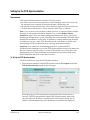
Setting Up the IP Parameters of the D9032 Encoder
Always verify that the IP parameters of the D9032 Encoder are correct before you
try to control the unit for the first time from the ROSA management system. Also do
as follows when a D9032 Encoder is added to or reinserted in the installation.
Proceed as follows to set the IP settings of the D9032 Encoder, and if necessary
change them:
1. Press the MENU key on the front panel of the D9032 Encoder.1)
The MENU key toggles between the start up display and the main menu.
2. From the main menu press the RIGHT arrow key 4 times to navigate to the
system menu, and press SELECT. You have now entered the system menu.
3. From the system menu press the RIGHT arrow once and press SELECT. You
have now entered the IP menu.
4. Go to the wanted menu item and press the SELECT.
You use the right and left arrow keys to navigate to the wanted menu item.
5. If necessary change the value.
Use the right arrow key to navigate to the digit to change and press one of the
numeric keys to enter a value. Press the SELECT key to store the entered
value(s).
6. If necessary, change the other IP parameters as described in steps 3 and 4 above.
7. Press the UP arrow to leave the IP menu.
Note: When you leave the IP menu by pressing the UP arrow key, the IP, Mask
and Gateway parameters are validated against each other and stored. Any
inconsistencies will be shown in the display.
Important: For the changes to take effect you must reset the D9032 Encoder
after you have finished setting or changing the IP address, subnet mask and
default gateway. Proceed as follows to reset the D9032 Encoder.
8. From the main menu press the RIGHT arrow key 4 times to navigate to the
system menu and press SELECT key. You have now entered the System menu.
9. Press the RIGHT arrow key twice to go to the Reset menu. Press SELECT twice
to confirm the reset.
Note: The reset make take up to 90 seconds.
1)You can also set up the IP address of the D9032 Encoder from the GUI
4019394 Rev B
Quick Setup - Read Me First!
1-3
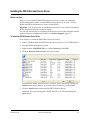
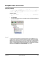
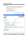
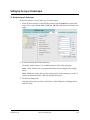
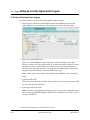
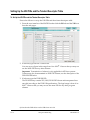
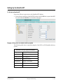
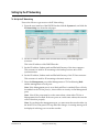
Setting up the D9032 Encoders from ROSA or Via the Web Interface
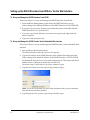
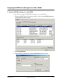
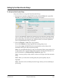
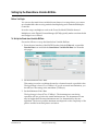
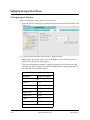
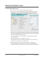
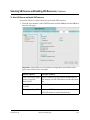
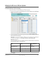
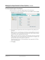
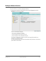
To Set up and Manage the D9032 Encoders From ROSA
Proceed as follows to set up and manage the D9032 Encoders from ROSA:
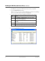
1. From the ROSA Management system select the D9032 Encoder to set up.
Unless changed, the default IP address of the D9032 Encoder is 150.158.230.250.
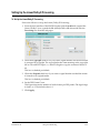
2. If you haven’t previously defined a user name and password double click the
D9032 Encoder icon to open the GUI.
3. If you have previously defined a user name and a password, right-click and
select Properties.
4. Type user name and password.
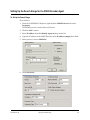
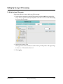
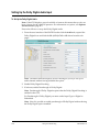
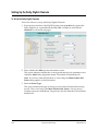
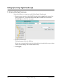
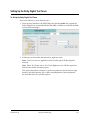
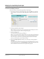
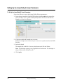
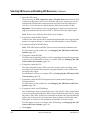
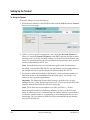
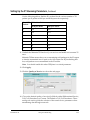
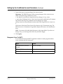
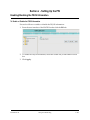
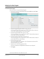
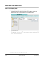
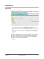
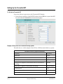
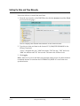
To Set up and Manage the D9032 Encoder Via the Embedded Web Interface
Proceed as follows to set up and manage the D9032 Encoder via the embedded Web
interface:
1. Start up Microsoft Internet Explorer.
The Internet Explorer must be version 6.0 or greater.
2. Type the IP address of the D9032 Encoder in the Address Bar and press Enter.
Unless changed the default IP address of the D9032 Encoder is 150.158.230.250.
Per default the Encoder has no user name and password. This means that the IP
address alone is sufficient to launch the encoder GUI.
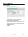
Proceed to steps 3 and 4 below if you have created a logon.
3. Type the user name if you have previously created a logon.
Hint: If you have forgotten your user name and password you can reset them
from the front panel user interface.
4. Type the password if you have previously created a logon.
1-4
Quick Setup - Read Me First!
4019394 Rev B
Chapter 2
Introduction
Overview
Introduction
This chapter is a general introduction to the Encoder Model D9032. It describes the
most common applications and interfaces of the .
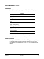
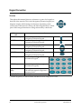
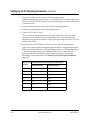
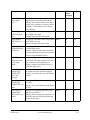
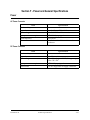
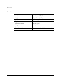
In This Chapter
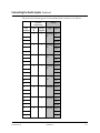
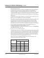
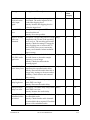
This chapter contains the following topics:
Topic
4019394 Rev B
See Page
Encoder Model D9032
2-2
Application Examples
2-6
Video Interfaces
2-8
Audio and Data Interfaces
2-9
Transport Stream Outputs
2-11
Control and Management Interfaces
2-12
Introduction
2-1
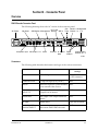
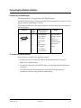
Encoder Model D9032
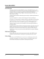
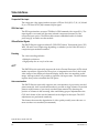
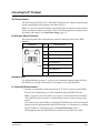
General Description
The design of the Encoder Model D9032 is compact. The D9032 Encoder is a 1U
encoder that fits into a 19-inch rack. It features one channel high-quality SDI and/or
composite video processing. It is targeted at distribution and contribution
applications and supports Dolby® Digital, Linear, passthrough of Dolby E, and
Layer II audio encoding
The D9032 Encoder features advanced pre-processing for optimum performance at
low bit rates.
Optional PreSightPlus™ combined with the Regulus™ Statistical Multiplex
Controller is one of the industry’s leading solutions for bandwidth saving encoding.
The D9032 Encoder offers built-in support for SCTE35 digital program insertion
(DPI), which will be used for ad-insertion applications in the digital domain.
Transport output is provided via ASI outputs as well as through IP (100 Base-T)
streaming outputs.
The D9032 Encoder features Ethernet management interface and supports the open
SNMP communication protocol for easy integration into the ROSA control and
management system from Scientific Atlanta or into 3rd party SNMP managers.
Alternatively you may set up and control the D9032 Encoder using the embedded
web interface.
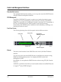
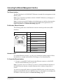
ROSA Control and Management
ROSA enables full control and monitoring functionality of the D9032 Encoder
installations with redundancy switching, error reporting and remote control.
Software Update
All software in the D9032 Encoder is stored in non-volatile memory that can be
electrically programmed. New software releases for the D9032 Encoder can be
downloaded via the Ethernet 10/100 Base-T Management interface.
2-2
Introduction
4019394 Rev B
Encoder Model D9032, Continued
Software Options
The table lists the various software options which can be installed by the use of a
license key. As can be seen from the list some of the options are pre-installed
Description
Pre-analysisa)
VBIa)
DPI signalling
Statistical Multiplexing
4:2:2
Noise Reductionb)
Dolby Digital Channel 1b)
Dolby Digital Channel 2b)
Dolby Digital Channel 3b)c)
Dolby Digital Channel 4b)c)
Auto-concatenation
Advanced Video Input - SDI
a. Pre-installed in all versions of the product
b. Pre-installed in all North American basic configurations
c. Pre-installed in North American basic configurations with 4 stereo pairs of audio
Note: All installed options are enabled at delivery.
Video and Audio Channels
You may order the D9032 Encoder with either one SDI input, one composite input,
or with both. You may order the D9032 Encoder with either two or four stereo
audio channels. The audio channels may be part of the video or stand-alone audio
channels.
4019394 Rev B
Introduction
2-3
Encoder Model D9032, Continued
Encoding Bit Rates
Video and audio data can be encoded at the following bit rates and coding
standards:
Input signal
Video signal
Audio signal
Bit rate
Coding standard
0.5 to 15 Mbit/s
MPEG-2 Main Profile at Main
Level (MP@ML)
1.5 to 50 Mbit/s
4:2:2 Profile at Main levela)
32 to 384 kbit/s
MPEG-1 Layer II
56 to 640 kbit/s
Dolby Digitala)
Dolby Digital passthrough
2,399,968 bit/s
Linear/Dolby E
a. Requires a license
VBI and Related Signals
The following VBI signals are supported for 625 lines PAL, 625 lines SDI, 525 lines
NTSC and 525 lines SDI:
625 lines PAL
•
•
•
•
•
•
•
Transparent lines
DVB-VBI Teletext
Teletext B
VPS
VITC
AFD WSS
ETSI WSS
625 lines SDI
•
•
•
•
•
•
•
•
•
525 lines NTSC
Transparent lines • Transparent
lines
DVB-VBI Teletext
•
VITC
Teletext B
• Closed
VPS
Captionsa)
VITC
AFD WSS
ETSI WSS
VII
EDH
525 lines SDI
• Transparent
lines
• VITC
• VII
• Closed
Captionsa)
• EDH
a. The Closed Captions feature supports the transmission of Content Advisory Data (CA) from the
incoming video signal to the outgoing transport stream.
Reference Input
The D9032 Encoder provides a reference input for internal frame synchronization of
the video input to an external studio reference.
2-4
Introduction
4019394 Rev B
Encoder Model D9032, Continued
Pre-Processing
The pre-processing includes:
• PreSightPlus pre-analysis with look-ahead for improved statistical multiplexing
and normal fixed rate encoding. The PreSightPlus pre-analysis option includes
adaptive quantization matrices which has a positive impact on both PQR values
and the subjective visual impression. The pre-analysis includes a feature to
dynamically change MPEG-2 quantization matrices and the possibility to enable
3:2 pulldown inversion for 525 lines material.
• PreSightPlus noise reduction option (adaptive “motion-compensated” temporal
filter, and adaptive low-pass spatial filter.)
• Dynamic/variable GOP, forced I to P and P to I frames.
• Horizontal luminance and chrominance low-pass filters.
The PreSightPlus video noise reduction removes noise and details that stress the
encoder at low bit rates. It is possible to adjust the filter manually during operation
without service interruption, or to set the filter to adjust automatically to the
encoding complexity of the video contents.
The PreSightPlus video noise reduction and pre-analysis features are options that
may be ordered with the D9032 Encoder or added later.
Sub-sampling
The D9032 Encoder supports subsambling. Sub-sampling decreases the resolution
of the source material in order to lower the amount of data to be encoded.
Transport Stream
The encoded data, carrying the video and audio signals, is internally multiplexed
into the MPEG-2 and DVB compliant transport stream when the D9032 Encoder is
used in a stand-alone or ROSA controlled application. The three ASI outputs always
carry the transport stream (TS).
4019394 Rev B
Introduction
2-5
Application Examples
Single Channel Encoding for Distribution
The D9032 Encoder can be used for single channel encoding in distribution
applications, i.e. for local program encoding, or other applications, where only a
few channels are needed.
VIDEO
AUDIO
ALARM
1
2 ABC
4 GHI
5 JKL
7 PQRS
8 TUV
ASI
3 DEF
6 MNO
SELECT
PREV
POWER
0
9 WXYZ
MENU
04-050
D9032 Encoder
Local/Regional Encoding
Often a locally generated program needs to be added to the distribution network.
This is where the D9032 Encoder comes in. A local program is encoded in the D9032
Encoder. The output from the D9032 Encoder is a single program transport stream.
With for example the Continuum DVP D9600 Re-multiplexer and Transport Stream
Processor you can insert the locally generated program into a multi program
transport stream from a satellite or a network.
Local Program
Single Program Transport Stream
ALARM
PO WER
1
2 ABC
4GHI
5 JKL
7PQRS
8 TUV
3 DEF
6 MNO
SELECT
PREV
0
9 WXYZ
MENU
D9032 Encoder
Video, Audio, Data
Multiple Program Transport
Stream with local program and
all/some programs from input
Multiple Program Transport Stream
from Satellite or Network
D96xx Re-multiplexer and
Transport Stream
Processor
2-6
Introduction
4019394 Rev B
Application Examples, Continued
Multichannel Statistical Encoding
The Regulus Statistical Multiplex Controller is an add-on unit for the D9032
Encoder. You may connect the Statistical Multiplex Controller to a number of
encoders so that they together may participate in statistical multiplexing.
The figure below shows how five video programs are statistically multiplexed and
inserted into a multi-program transport stream.
RE GULU S
S ta tistic a l M u ltip le x C o n tro lle r
P ower
A lar m
Fai llu re
C h a n n e l S ta tu s
1
2
3
4
5
6
7
8
9
10
12
11
13
14
16
15
R e g u lu s T M ,
S ta tis tica l M u ltip le x
C o n tro lle r
P ro g ra m 1
AL ARM
DV B
SE L EC T
P OW E R
1
2
4
5
7
8
3
ASI
6
9
0
P R EV
C o n tin u u m D V P
ME N U
TM
M o d e l D 9 0 3 0 En co d e r
D 9 0 3 2 E n co d e r
P ro g ra m
2
AL ARM
DV B
SE L EC T
P OW E R
1
2
4
5
7
8
3
6
9
0
P R EV
C o n tin u u m D V P
ME N U
TM
M o d e l D 9 0 3 0 En co d e r
ASI
D 9 0 3 2 E n co d e r
C o n t in u u m D V P
P ro g ra m 3
AL ARM
DV B
SE L EC T
P OW E R
1
2
4
5
7
8
3
6
9
0
P R EV
C o n tin u u m D V P
ME N U
TM
M o d e l D 9 0 3 0 En co d e r
ASI
AL ARM
DV B
SE L EC T
P OW E R
1
2
4
5
7
8
xxx
ASI
D V P TM
C o n tin u u m
D 9616,
R e -m u ltip le xe r a n d T ra n s p o rt
S tre a m P ro c e s so r
3
6
9
0
P R EV
xxx
xxx
D 9 0 3 2 E n co d e r
P ro g ra m 4
R e -M u lti p le xe r a n d T ra n s p o rt S tre a m P ro c e sso r
ME N U
C o n tin u u m D V P
TM
M o d e l D 9 0 3 0 En c o d e r
ASI
D 9032 Encoder
P ro g ra m 5
A LA RM
D VB
PO W ER
S EL E C T
1
2
4
5
7
8
P R EV
0
3
6
9
ME N U
C o n tin u u m D V P
TM
M o d e l D 9 0 3 0 E n co d e r
ASI
D 9 0 3 2 E n co d e r
04-126
ROSA
4019394 Rev B
Introduction
2-7
Video Interfaces
Composite Video Input
The composite video input interface accepts a 625-line PAL (B, D, G, H, I, K, M and
N) or a 525-lines NTSC (M) formatted input signal.
SDI Video Input
The SDI input interface accepts a 270 Mbit/s SDI formatted video input (D-1). The
input signal is converted into the same internal component format as for the
composite input option. The SDI module extracts embedded audio for further
processing by an audio encoder module.
VBI and Related Signals
The D9032 Encoder supports teletext B, DVB-VBI Teletext, Transparent Lines, VPS,
WSS, VII and Closed Captioning depending on whether you have the SDI and/or
composite input modules installed.
Encoding
The video encoding includes:
• Multiple resolutions
• High quality also at very low bit rates
AFD1)
The D9032 Encoder optionally supports the Active Format Descriptor (AFD) which
makes it possible to signal to the set-top box or integrated receiver how the coded
video image is best displayed when the display device does not match the coded
image. Amongst others it is possible to signal the 14:9 aspect ratio. The AFD feature
requires that you have installed the VBI option.
Auto-concatenation
The D9032 Encoder optionally supports auto-concatenation of previously encoded
picture material. Auto-concatenation makes it possible to align I-frames of encoded
pictures with I-frames of previously encoded input material. By detecting the
position of I-frames in the incoming video and making proper adjustments to the
GOP, the I-frames of the encoded material can be aligned to the input. The GOP
adjustments are performed seamlessly.
This feature decreases the degradation of video quality usually seen when two or
more encoders are cascaded (concatenated).
1)In 625 lines mode with VII.
2-8
Introduction
4019394 Rev B
Audio and Data Interfaces
Audio Input
Four audio stereo channels can be input at the D9032 Encoder. Each of the audio
inputs accept analog, digital AES/EBU or AES-3id input. Audio channels 1 and 2
(i.e. on-board audio) are only able to support S/PDIF and not AES/EBU. You can
assign the encoded audio channels, in multiples of two, to the video program or to
independent audio only programs.
Digital Audio Interface
The audio input interface accepts a digital input, formatted as an AES/EBU
encoded signal. Left and right channel samples are extracted from the input and
synchronized to the video signal.
Analog Audio Interface
The audio input interface features balanced left and right analog inputs. For each
analog audio input you can set the input impedance and the clipping level.
Embedded Audio
The audio input interface can be configured to accept an input of embedded audio
from the SDI video input interface.
Audio Encoding Formats
The supported audio encoding formats are MPEG-1 layer II, Dolby Digital, linear
audio, and passthrough of Dolby Digital.
Layer II Encoding
The audio inputs may be encoded in the following ways:
• a stereo program
• a joint stereo program
• two independent mono programs
• Dual channel
You can set the sampling frequency for the digitizing process to one of the
following values:
• 32 kHz
• 44.1 kHz
• 48 kHz.
For audio attached to the video the D9032 Encoder locks the audio sampling
frequency to the video. For AES/EBU digital input signals, the D9032 Encoder
automatically adapts the incoming rate by using sample rate conversion.
4019394 Rev B
Introduction
2-9
Audio and Data Interfaces, Continued
Dolby Digital Encoding
The audio inputs may be encoded in the following ways:
• Dual Mono 1+1
• Stereo 2/0
• Mono 1/0
You can set the sampling frequency for the digitizing process to one of the
following values:
• 32 kHz
• 44.1 kHz
• 48 kHz.
The D9032 Encoder locks the audio sampling frequency to the video. For AES/EBU
digital input signals, the D9032 Encoder automatically adapts the incoming rate by
using sample rate conversion.
Dolby Digital Passthrough
The D9032 Encoder supports passthrough of up to four pre-encoded Dolby Digital
stereo channels.
Linear Audio and Dolby E Passthrough
The D9032 Encoder supports passthrough of up to 8 pre-encoded Dolby E channels.
The D9032 Encoder also supports Linear audio.
Audio Only
The D9032 Encoder supports four mono or two stereo audio-only programs. One or
more audio sources can be combined to make up a program.
2-10
Introduction
4019394 Rev B
Transport Stream Outputs
DVB-ASI Transport Stream Output
The D9032 Encoder has three DVB-ASI outputs. These outputs can be used as an
input for e.g. a satellite modem or a multiplexer. One of the outputs is an ASI
monitor output for monitoring of the outgoing data stream. Unlike the two other
ASI outputs the monitor output cannot be muted.
The outputs support SI generation with standard tables compliant to MPEG-2 and
DVB.
IP Transport Stream Output
The D9032 Encoder has two IP TS outputs. These outputs can be used as inputs to
IP networks.
The output rate follows the ASI output rate.
4019394 Rev B
Introduction
2-11
Control and Management Interfaces
Embedded Web Interface
The embedded Web Interface enables you to set up and control the D9032 Encoder
using the Ethernet management interface.
ROSA Management
The ROSA/COPERNICUS system is a multi-server/multi-client based system
enabling you to set up and manage a whole network of encoders. In the ROSA
Single-User system the server and client is located on the same PC. Consequently it
has only one simultaneous user. ROSA enables control and monitoring
functionality of the D9032 Encoder installations with redundancy switching, error
reporting and remote control.
Front Panel Control
The following drawing shows the front panel with its different sections.
LCD Panel
Alarm LED
Navigation/
Selection Keypad
04-097
Power LED
Numeric Keypad
Ethernet
The main control interface for the D9032 Encoder is the 10/100 BaseT Ethernet
interface.
You can set up and control the D9032 Encoder via the Ethernet connection using
SNMP and a management system - for example; the ROSA control and
management system.
From ROSA you can update the D9032 Encoder software using FTP (File Transfer
Protocol).
A MIB file is included in the delivery from Scientific Atlanta for the D9032 Encoder
to support 3rd party SNMP managers.
2-12
Introduction
4019394 Rev B
Control and Management Interfaces, Continued
Alarm Relay Interface
During operation the condition of the D9032 Encoder can be monitored by three
relay contact outputs, accessible from the Alarm connector on the rear panel of the
D9032 Encoder. Furthermore, the alarm status is signalled by Alarm LEDs on the
front of the D9032 Encoder and by messages sent via the management system.
Contact Closure and Cue Tone Interfaces
The contact closure and cue tone interfaces are used for Digital Program Insertion
(DPI). DPI allows for the insertion of advertisements into program content in the
digital domain. The supported DPI messages are in accordance with the SCTE 35
specification.
Redundancy
The D9032 Encoder driver software supplied with the ROSA/COPERNICUS
management system supports the necessary functions for backup, using the “DHB
task” product. For further information, see DHB Task, ROSA Digital Headend Backup
Task, User Manual 6985066.
Also the ROSA Element Manager is capable of backing up D9032 Encoders. For
further information, see ROSA - Element Manager - User’s Guide, part number
64005743.
4019394 Rev B
Introduction
2-13
2-14
Introduction
4019394 Rev B
Chapter 3
Installation
Overview
Introduction
This chapter describes how to install the Encoder Model D9032. Before installing the
D9032 Encoder, read all safety precautions and guidelines thoroughly.
Qualified Personnel
Only appropriately qualified and trained personnel should attempt to install,
operate or maintain the D9032 Encoder.
WARNING:
Allow only qualified personnel to install this product. Otherwise, personal
injury or equipment damage may occur.
In This Chapter
This chapter contains the following topics:
Topic
4019394 Rev B
See Page
Section A - Rack Installation
3-3
General
3-3
Installing the D9032 Encoder
3-4
Connection of Scientific Atlanta Equipment to DC Power Sources
3-5
Section B - Connector Panel
3-9
Overview
3-9
Section C - Connecting the Input/Output Signals
3-11
Connecting the Video and Reference Signal Inputs
3-11
Connecting the Audio Inputs
3-12
Connecting to the Contact Closure or Cue Tone Interfaces
3-16
Connecting the Statmux Interface
3-17
Connecting an External Alarm System
3-18
Connecting the Ethernet Management Interface
3-19
Connecting the ASI Outputs and the ASI Monitor Decoder
3-20
Connecting the IP TS Output
3-21
Installation
3-1
Topic
Connecting the Aux Output
3-2
See Page
3-22
Installation
4019394 Rev B
Section A - Rack Installation
General
Power Connection
As Scientific Atlanta units are designed for 24 hours’ operation, some products do
not have a power switch. In this case the mains cord and/or DC power supply cable
serve(s) as the mains disconnect device.
WARNING:
Make sure that at least one end of the power cable(s) remains easily accessible
for unplugging, if you need to switch off the unit. For example: Ensure that the
socket outlet is installed near the product.
4019394 Rev B
Installation
3-3
Installing the D9032 Encoder
Rack Mounted
The D9032 Encoder is a 1U unit with connector access at the rear panel. The D9032
Encoder is intended for mounting in a standard 19" rack.
Cooling
The D9032 Encoder is cooled by the use of fans. The air intake is from the front
panel and the air outlet is on the rear.
CAUTION:
The inlet air temperature must not exceed 50°C/122 °F at any time.
Grounding
You must ensure that the unit is properly connected to ground in order to meet
safety and EMC requirements. Before any other connection is made, the unit must
be connected to a protected ground terminal as described below:
• Via the three wire power cord of the AC power supply. This connection is
mandatory.
• In addition, via the protective ground terminal on the rear panel of the unit. This
connection provides additional protection of the equipment.
To Mount the D9032 Encoder
To mount the D9032 Encoder in a rack do the following:
1. Mount rails in the rack to support each D9032 Encoder to be installed.
For further information, contact your rack supplier.
2. Place the D9032 Encoder in its position in the rack.
3. Mount the D9032 Encoder securely to the rack by securing four screws in the
holes in the front panel mounting flanges.
4. Make sure that air can circulate freely from the front of the D9032 Encoder.
5. Do not block the air outlet holes on the back of the D9032 Encoder.
To Connect AC Power
To connect AC power to the D9032 Encoder do the following:
1. Connect the power cord (supplied with the D9032 Encoder) between the rear
panel power receptacle and an 100 to 240 V AC power outlet.
2. Make sure that the power cable is connected to protective ground.
See Grounding at the beginning of this section.
3-4
Installation
4019394 Rev B
Connection of Scientific Atlanta Equipment to DC Power Sources
General
Some Scientific Atlanta products can be powered by DC power supplies.
In general two categories of DC power supply systems are considered:
• -48 V DC Nominal Voltage systems with absolute maximum values below 60
V DC (SELV).
• -48 to –60 V DC Nominal Voltage systems with absolute maximum values below
75 V DC. (NON SELV)
For the allowable nominal voltage, refer to the Ratings/Identification label on your
product.
-48 V DC Power Source
For equipment designed to be powered by a –48 V DC power source, and having a
Normal Service Voltage Range not exceeding –38 to –58 V DC, the following safety
warnings and guidelines apply:
• Independent units and chassis must be connected to the –48 V DC power source
via the mating field wiring connector. Furthermore, the following applies:
- Use a listed DC rated Branch Circuit protection in accordance with the wire
size, and with a maximum of 15 A current. The circuit protection must be
placed in the hot wire.
- The -48 V DC power source must comply with the safety extra-low voltage
(SELV) requirements in the UL 60950, CSA C22.2 No. 60950, EN 60950 and IEC
60950 standards.
- The -48 V DC power source must be electrically isolated from the AC source in
accordance with the standard of the country where you are installing the
product.
- The wire size of the cable used to connect a product to the DC distribution
module or bus bar must have the appropriate wire size to avoid overloading.
We recommend a minimum of 1.5 mm² (or AWG16) for 15 A fusing.
- Always wire the protective earth terminal of the DC power supply connector or
cable.
4019394 Rev B
Installation
3-5
Connection of Scientific Atlanta Equipment to DC Power Sources, Continued
-48 to -60 V DC Power Source
Some Scientific Atlanta products can be equipped with a DC power supply, which
accommodates both -48 V DC and -60 V DC Nominal power supply systems.
(Normal Service Voltage Range not exceeding -36 V DC to -72 V DC).
For the allowable nominal voltage, refer to the Ratings/Identification label on your
product.
In this case, the device is provided with a dedicated MATE-N-LOK type connector
or an AMP type III connector.
A mating connector is provided in the accessory set of the unit.
For this category of equipment, the safety considerations for handling dangerous
voltages are applicable.
WARNING:
Use the same level of safety precautions for this equipment and power source as
for the AC power source.
For units powered by a -60 V DC Nominal power source, observe the following
safety warnings and guidelines:
• Use a listed DC rated Branch Circuit protection in accordance with the wire size,
and with a maximum of 15 A current. The circuit protection must be placed in the
hot wire in order to protect the rack wiring and the power connector of the D9032
Encoder. We recommend a slow-blow type of fuse in order to pass the in-rush
current during power-up.
• The -60 V DC power source must be electrically isolated from the Mains ACc
source in accordance with the standard of the country where you are installing
the product.
• The wire size of the cable used to connect a product to the DC distribution
module or bus bar must have the appropriate wire size to avoid overloading.
We recommend a minimum of 1.5 mm² (or AWG16) for 15 A fusing.
• Always wire the protective earth terminal of the DC power supply connector or
cable.
3-6
Installation
4019394 Rev B
Connection of Scientific Atlanta Equipment to DC Power Sources, Continued
Connection to Centralized DC Power Systems
WARNING:
Only units designed and rated for connection to –48 to –60 V DC Nominal
power sources are suitable for connection to “Centralized DC Power Systems”.
A centralized DC power distribution system (typically -48 V DC) is a power system
consisting of open batteries, charger/rectifier circuits, and primary and secondary
distribution equipment intended to provide power to equipment loads. Two types
of systems exist:
• Source earthed DC power systems, in which the connection to the earthing
electrode is located at the source, and separate earthed and protective earth
conductors, are provided throughout the system.
• DC power system earthed at the equipment location, in which the connection to
the earthing electrode is located in the area where the load equipment is to be
installed.
Scientific Atlanta equipment is designed for connection to Source earthed DC
power systems.
A typical power distribution arrangement is shown below:
Charge
Bus
Discharge
Bus
Batteries
Primary
Distribution
Secondary
Distribution
-
DC Powered
Equipment
+
Charger
/
Rectifier
Main
Bonding
Jumper
Battery Battery
Bank Bank
No 2
No 1
Equipment
grounding
conductor
Secondary
power board
Primary
Powerboard
+
Equipment
grounding
conductors
+
Grounding
Electrode
Conductor
4019394 Rev B
Main
Bonding Jumper
Grounding
Electrode
Installation
3-7
Connection of Scientific Atlanta Equipment to DC Power Sources, Continued
To Connect DC Power
Check the wire size, power source and DC fuse as described above, before
connecting to DC power. Connect to DC power as follows:
1. Connect the D9032 Encoder to the DC source through a distribution module or a
bus bar being part of the rack.
2. Make sure that the power cable is connected to protective ground.
If you use a floating DC power source, the positive terminal must be connected
to chassis and local ground to prevent building up of dangerous voltages.
The DC power supply input is floating with respect to chassis ground on the
D9032 Encoder.
DC Connector Pin Allocation
The following drawing shows the pin allocation for the DC connector.
+
04-129
3-8
Installation
4019394 Rev B
Section B - Connector Panel
Overview
D9032 Encoder Connector Panel
The following drawing shows the AC version of the connector panel.
AC Power
IP TS Out
ASI Monitor Management Backup SDI In
Not Used
Composite Input
ASI Output 1 +2
Alarm
Cue Contact Analog Audio
Tone Closure In, 1 + 2
Statmux IP TS Out
Main
Digital
Audio In
Analog/Digital
Audio In, 3 + 4
04-032
Connectors
The following table describes the function and type of the various connectors:
Connector
4019394 Rev B
Function
Connector Number
and Type
Power
AC or DC power
IEC 60320 Sheet 14
or DC connector
COMPOSITE IN
Composite input (PAL/NTSC)
BNC
REF IN
Reference input for synchronization
to an external video source.
BNC
ASI OUT 1
ASI OUT 2
ASI output. Two identical outputs.
Outputs can be muted.
BNC
ASI Monitor
ASI output. This output cannot be
muted.
BNC
ALARM
Alarm relays
9-pin sub-D female
10/100 BASE-T
MANAGEMENT
For control and management of local RJ45
and remote D9032 Encoder units.
Installation
3-9
Overview, Continued
Connector
Function
Connector Number
and Type
STATMUX
Connection to the Statistical
Multiplex Controller
9-pin sub-D female
SDI IN
SDI input
BNC
CUE TONE
CONTACT
CLOSURE
Cue tones for DPI triggering
Contact closure for DPI triggering
Terminal block
ANA/DIG AUDIO
IN 3 & 4
Analog and digital audio input for
channels 3 and 4
Terminal block
Important: All cabling must be shielded and grounded at both ends except for
Power, Alarm, and Cue Tone contact closures.
3-10
Installation
4019394 Rev B
Section C - Connecting the Input/Output Signals
Connecting the Video and Reference Signal Inputs
Connectors for the Video and Reference Signal Inputs
Both the SDI, The composite video input and reference input connectors are of the
BNC type and are internally terminated.
The following video and reference input signals are supported:
• 270 Mbit/s digital 525 and 625 lines SDI, or
• Analog composite PAL (B, D, G, H, I and K) and NTSC (M)
• Composite reference input
To Connect to the Video Input
Do as follows to connect to the video input:
1. Connect the video input signal to the SDI In or Composite In connector.
Use a 75-ohm double-braided coax cable.
To Connect the Reference Input
Do as follows to connect to the reference input:
1. Connect the reference input signal to the REF IN connector.
Use a 75-ohm double-braided coax cable.
4019394 Rev B
Installation
3-11
Connecting the Audio Inputs
Connectors for the Audio Input
The basic configuration of the D9032 Encoder supports 2 stereo channels.
Optionally it supports 2 additional stereo channels.
Digital audio for channels 1 and 2 is input at the BNC connector called Digital
Audio In.
The following drawing shows the two BNC connectors:
The connector label Analog Audio In 1 & 2 denotes that analog audio for channels 1
and 2 is input at the top row of pins on the terminal block connector.
The connector label Ana/Dig Audio In 3 & 4 denotes that analog or digital audio for
channels 3 and 4 is input at the bottom row of pins on the terminal block connector .
3-12
Installation
4019394 Rev B
Connecting the Audio Inputs, Continued
The pinout for the analog part of the terminal block connector is as follows:
Channel
Numbering
Pin
Number
Layer
II
Dolby
Digital
1
1
Analog
Type
2
Analog Left +
In
Left -
3
Shield
1
4
2
1
5
Analog Right +
In
Right Shield
6
8
Analog Left +
In
Left -
9
Shield
7
10
3
4
2
2
11
Analog Right +
In
Right Shield
12
14
Analog Left +
In
Left -
15
Shield
13
16
5
6
3
3
Analog Right +
17
Right -
18
Shield
19
7
4
Analog Left +
20
Left -
21
Shield
22
4019394 Rev B
Signal
8
4
Analog Right +
23
Right -
24
Shield
Installation
3-13
Connecting the Audio Inputs, Continued
The pinout for the digital part of the terminal block connector is as follows:
Channel
Numbering
Pin
Number
Layer
II
Dolby
Digital
Type
5&6
3
14
Digital
In
15
Digital
Out
16
17
20
7&8
4
Digital
In
21
22
23
Digital
Out
Type
Installation
Signal
N/A
+
Digital In Signal
-
Ground
Shield
Shield
Signal
Ground
+
Digital
Out
Signal
Ground
Shield
Digital In
Signal
-
Ground
Shield
Shield
Signal
Ground
Shield
24
3-14
AES-3id
Shield
18
19
Signal
N/A
1 to 12
13
AES/EBU
Digital
Out
Signal
Ground
Shield
4019394 Rev B
Connecting the Audio Inputs, Continued
To Connect the Audio Inputs
Do as follows to connect the audio inputs:
1. For digital channels 1 and 2 connect the audio input to the Digital Audio In
connector.
Hint: For digital audio connections, use a coaxial cable designed for 75-ohm
AES-3id.
2. For analog channels 1 and 2 do as follows:
Spring Cage Plug
Connector
Step Action
1
Connect the analog audio input cable to the
spring cage plug connector.
Use a flat-blades screwdriver with a width of
2 mm and a maximum thickness of 0.4 mm to
press in the spring representing the pin to be
connected.
Push the wire in the hole above the spring
and release the spring.
2
Connect the spring cage plug connector to
the Analog Audio In 1 & 2 part of the
terminal block connector.
3. For channels 3 and 4 connect the analog or digital audio input to the Ana/Dig
Audio In 3 & 4 part of the terminal block connector. The input type of channels 3
and 4 is set up in the GUI.
Note: For digital audio connections, use a balanced cable designed for 110-ohm
AES-EBU digital audio or a coaxial cable designed for 75-ohm AES-3id. Use a
high-quality balanced audio cable for the analog inputs.
If you have many or heavy audio cables connected to the D9032 Encoder, you
may need to suspend the cables in your rack to prevent unnecessary mechanical
stress on the audio connector.
4. If relevant, use the Digital Out pins of channels 3 and/or 4 to synchronize
external equipment to a reference clock. The reference clock is locked to the
video.
4019394 Rev B
Installation
3-15
Connecting to the Contact Closure or Cue Tone Interfaces
Contact Closure and Cue Tone Connector
The D9032 Encoder has a contact closure and a cue tone interface which can be used
to trigger digital program insertion (DPI). The contact closure interface has 8 inputs.
The cue tone interface has two inputs.
Pin Allocation
The connector labeled CUE TONE CONTACT CLOSURE is a 24 pin terminal
block connector.
The following table shows the connector and the pin allocation.
Connector Drawing
Pin
Description
Number
Pin
Description
Number
1
Cue Tone In + 13
NC
2
Cue Tone In - 14
NC
3
Ground
15
NC
4
NC
16
INC
5
Contact 1
17
Contact 5
6
Ground
18
Ground
7
Contact 2
19
Contact 6
8
Ground
20
Ground
9
Contact 3
21
Contact 7
10
Ground
22
Ground
11
Contact 4
23
Contact 8
12
Ground
24
Ground
Note: Contact open = not connected (internal pull-up).
Contact closed = connected to ground.
To Connect to the Contact Closure Interface
Connect the external contact closure equipment to the contact closure interface.
External contact closure equipment could be a Monroe DTMF decoder.
To Connect to the Cue Tone Interface
Connect the external cue tone equipment to the cue tone interface. External cue tone
equipment could be a PowerVu® D9850 Program Receiver.
3-16
Installation
4019394 Rev B
Connecting the Statmux Interface
Connector for the Statmux Input
The Statmux input is not applicable to the D9032 Encoder.
The D9032 Encoder has one bidirectional RS-232 data channel for connection to the
Regulus Statistical Multiplex Controller.
The following table shows the female Statmux connector and the pin allocation for
the RS-232 input.
Connector
1
9
Pin
number
1
2
3
4
5
6
7
8
9
RS-232 Connector
Pin allocation
Not connected
RxD (output)
TxD (input)
DTR (input)
GND
DSR (output)
RTS (input)
CTS (output)
Not connected
Signal
RS 232-E data
channel, at a bit
rate of
38,400 baud
Connector type:
9-pin sub-D
female
To Connect the Statmux Interface
Do as follows to connect to the Statmux interface:
1. Connect the one-to-one RS-232 cable to the Statmux Interface connector.
Note: Use a shielded cable.
2. Connect the other end of the RS-232 cable to the Regulus Statistical Multiplex
Controller.
The D9032 Encoder automatically sets up the RS-232 communication
parameters when choosing statistical multiplexing.
4019394 Rev B
Installation
3-17
Connecting an External Alarm System
Connector for an External Alarm System
The D9032 Encoder is equipped with a connector for alarm relay outputs for remote
alarm signaling.
The Alarm output connector is a 9-pin Sub-D female connector. The following
drawing shows the connector and the pin allocation table for the Alarm output
connector.
Connector
HD
Relay
name
Function
Normally
closed pin
Common
pin
Normally
open pin
A
A-Alarm
6
2
1
B
B-Alarm
8
C
C-Alarm
5
1. Connect the cable from the external alarm system to the alarm connector.
Example, Alarm Relays
The following figure shows an example of how the alarm relays work.
6 Normally Closed (Inactive)
2 Common
1 Normally Open (Active)
For example, for an A-alarm under normal operational conditions (no alarm), pin 6
is closed, that is connected to pin 2 and pin 1 is open. However, should an alarm
condition occur pin 6 is open and pin 1 is closed, that is connected to pin 2. This
means that the A-alarm is active and the A-alarm LED lights on the front panel.
Note: The A-alarm relay is always activated when the power is off or the D9032
Encoder is booting, whereas the other alarm relays maintain their status.
For example, if a B-alarm relay is inactive when the power is switched off, it stays
inactive. However, if it is active when the power is switched off, it stays active.
For information about the maximum relay load, see Alarm Interface, page A-19.
3-18
Installation
4019394 Rev B
Connecting the Ethernet Management Interface
The Ethernet Interface
The RJ-45 interface for 10/100 BASE-T Ethernet is intended for management via the
ROSA system.
Note: If you experience problems with the 10 BASE-T Ethernet, try changing to a
100 BASE-T connection.
Note: You must set up the IP address, the default gateway and the subnet mask to
match the network connection. This is done through the front panel menu. For
further information, see Front Panel Setup, page 1-3.
Pin Allocation, Ethernet Connector
The following table shows the Ethernet connector and the pin allocation (MDI
interface):
Connector
1
Pin
8
00-052
Pin allocation
1
Tx+
2
Tx-
3
Rx+
4
Not connected
5
Not connected
6
Rx-
7
Not connected
8
Not connected
Informative Notes
For reliable Ethernet operation - to run over a maximum segment length of 100 m,
the cable has to comply with the EIA/TIA Category 5 wire specifications.
To Connect the Ethernet Interface
1. Connect a crossed RJ-45 cable between the Ethernet connector on the D9032
Encoder and the Ethernet port of your PC.
Note: You need a crossover cable if you want to connect the Ethernet interface of
the D9032 Encoder directly to another Ethernet device without using a hub or
switch.
You need to set up the IP address on both the D9032 Encoder (via the front panel
display) and the ROSA driver for D9032 Encoder. For information on setting up the
IP address via the front panel, see Front Panel Setup, page 1-3.
4019394 Rev B
Installation
3-19
Connecting the ASI Outputs and the ASI Monitor Decoder
To Connect the ASI Outputs
Do as follows to connect to the ASI output:
1. Connect the output signals from the D9032 Encoder connectors ASI OUT 1 and/
or ASI OUT2 to the ASI input connectors of the equipment after the D9032
Encoder.
Use a 75-ohm double-braided cable.
The equipment following the D9032 Encoder could be a Transport Stream
Multiplexer such as the combination of a Continuum DVP D9600 Remultiplexer and Transport Stream Processor.
Note: The two outputs are identical and can be used for back-up purposes.
2. If you want to check the ASI output signal, connect an ASI monitor to the ASI
monitor connector.
Note: The ASI monitor output cannot be muted, but otherwise it works just like
the two primary outputs.
3-20
Installation
4019394 Rev B
Connecting the IP TS Output
The Ethernet Interface
The RJ-45 interface IP TS OUT for 100 BASE-T Ethernet is for output of the transport
stream encapsulated in IP packets to the Main receiver.
Note: You must set up the IP address, the default gateway and the subnet mask in
order to match the network connection. This is done through the front panel menu.
For further information, see Front Panel Setup, page 1-3.
Pin Allocation, Ethernet Connector
The following table shows the Ethernet connector and the pin allocation (MDI
interface):
Connector
1
Pin
8
00-052
Pin allocation
1
Tx+
2
Tx-
3
Rx+
4
Not connected
5
Not connected
6
Rx-
7
Not connected
8
Not connected
Informative Notes
For reliable Ethernet operation - to run over a maximum segment length of 100 m,
the cable has to comply with the EIA/TIA Category 5 wire specifications.
To Connect the Ethernet Interface
1. Connect a crossed RJ-45 cable between the IP TS OUT connector on the D9032
Encoder and the Ethernet port of the equipment after the D9032 Encoder.
Note: You need a crossover cable if you want to connect the Ethernet interface
of the D9032 Encoder directly to another Ethernet device without using a hub/
switch.
You need to set up the IP address on both the D9032 Encoder (via the front panel
display) and the equipment after the D9032 Encoder. For information on setting
up the IP address via the front panel, see Front Panel Setup, page 1-3.
The equipment after the D9032 Encoder could be an IP router or a switch.
4019394 Rev B
Installation
3-21
Connecting the Aux Output
The Ethernet Interface
The RJ-45 interface Aux for 100 BASE-T Ethernet is for output of the transport
stream encapsulated in IP packets for the backup receiver.
Alternatively you may use this connector for PCR synchronization.
Note: You must set up the IP address, the default gateway and the subnet mask to
match the network connection. This is done through the front panel menu. For
further information, see Front Panel Setup, page 1-3.
Pin Allocation, Ethernet Connector
The table shows the Ethernet connector and the pin allocation (MDI interface):
Connector
1
Pin
8
00-052
Pin allocation
1
Tx+
2
Tx-
3
Rx+
4
Not connected
5
Not connected
6
Rx-
7
Not connected
8
Not connected
Informative Notes
For reliable Ethernet operation - to run over a maximum segment length of 100 m,
the cable has to comply with the EIA/TIA Category 5 wire specifications.
To Connect the Ethernet Interface
1. Connect a crossed RJ-45 cable between the Aux connector on the D9032 Encoder
and the Ethernet port of the equipment following the D9032 Encoder, i.e., a
backup receiver.
Note: A crossover cable is required to connect the Ethernet interface of the
D9032 Encoder directly to another Ethernet device without using a hub/switch.
You need to set up the IP address on both the D9032 Encoder (via the front panel
display) and the equipment following the D9032 Encoder. For information on
setting up the IP address via the front panel, see Front Panel Setup, page 1-3.
The equipment following the D9032 Encoder could be an IP router or a switch.
3-22
Installation
4019394 Rev B
Chapter 4
Front Panel Operation
Overview
Introduction
This chapter describes how to set up the D9032 Encoder using the front panel keys
and display.
In This Chapter
This chapter contains the following topics:
Topic
4019394 Rev B
See Page
About the Front Panel
4-2
Keypad Convention
4-4
Startup Screen
4-5
Main Menu
4-6
PSI Menu
4-7
Video Menu
4-9
Audio Menu
4-16
Output Menu
4-22
System Menu
4-25
Lock Menu
4-34
Front Panel Operation
4-1
About the Front Panel
Introduction
The D9032 Encoder is operated using controls and indicators on the front panel.
These include the numeric keypad, the Navigation/Selection keypad, the LCD, the
ALARM and POWER indicators. These are shown in the following
illustration:
LCD Panel
Alarm LED
Navigation/
Selection Keypad
04-097
Power LED
Numeric Keypad
Keypad
The numeric keypad is used to enter alphanumeric values. The MENU key sets the
software to the initial menu and the PREV key or the UP arrow key returns to the
previous menu. The PREV key can also be used to cancel a numeric entry at any
point during the entry sequence, and the LEFT arrow key allows backspacing
through the entry.
LCD
The LCD provides information on the selections available at any menu level,
current settings for parameters, and certain status and alarm indications. This is a
2x40, backlit LCD panel. The top line may be status data or identifier information. It
can also display optional functions available for tuning operations. The bottom line
will show selections or parameter values available using the navigation/selection
keypad. The items are selected by pressing the SELECT (center key) or DOWN
arrow key on the navigation/selection keypad.
Front Panel LEDs
For further information about the status signaling of the front panel LEDs, see Front
Panel LEDs, page 6-8.
4-2
Front Panel Operation
4019394 Rev B
About the Front Panel, Continued
Navigation/Selection Keypad
The navigation keys (LEFT, RIGHT, UP and DOWN) and the SELECT key on this
keypad are the primary controllers. Each navigation key performs various
functions, depending on the current state of the menu system (i.e., sometimes the
left navigation key is used to backspace over an entry and or in some cases to move
to a different menu item). Once the cursor is over the desired function, pressing the
DOWN arrow key moves to a different menu or changes a setting. Pressing the
SELECT key stores any entered values.
4019394 Rev B
Front Panel Operation
4-3
Keypad Convention
Overview
Throughout this manual, there are references to parts of a keypad on
the front of the encoder. This is the Navigation/Selection keypad (see
diagram at right), which changes its function, depending on the
current state of the menu. For clarity, the following table shows which
parts of this integral interface are being referenced by which term.
When you see
this…
LEFT Arrow key
RIGHT Arrow key
UP Arrow key
DOWN Arrow key
SELECT key
PREV key
MENU key
Alphanumeric
Entry
F1, F,2, F3, F4
It means…
Press the key on the left side of the
Navigation/Selection Keypad.
Press the key on the right side of the
Navigation/Selection Keypad.
Press the key on the top of the
Navigation/Selection Keypad.
Press the key on the bottom of the
Navigation/Selection Keypad.
Press the key in the center of the
Navigation/Selection Keypad.
Press the key on the lower left of
the numeric keypada).
Press the key on the lower right of
the numeric keypada).
Pressing the numeric keys 0-9 once
will enter the respective digit into a
data entry field.
Not Implemented.
a. Numeric keypad keys are uniform. MENU and PREV have been enlarged here for effect.
4-4
Front Panel Operation
4019394 Rev B
Startup Screen
Structure
On power up and initialization, an identifying startup screen displays the system
name, the video program number, the program name and the IP address of the unit.
The startup screen contains the following parameters:
ProgNo ProgName
D9032
IP Add.
System Name
Description:
The system name as set up from the software GUI. The system
name is centered on the top line of the Startup screen and is not
displayed on sub-pages. It is used for uniquely identifying the
D9032 Encoder. The system name is also displayed in the top right
corner of all software GUI pages, see Reading the System
Information or Managing the System, page 5-121.
Description:
The video program number. The program number is set up from
the PSI menu, see Video Programs, ProgNo, page 4-7.
Description:
The video program name. The program name is set up from the
GUI, see Setting Up the Video Program, page 5-105.
Description:
The IP address of the D9032 Encoder. The IP address is set up from
the System menu, see IP, Management IP, IP Address, page 4-25.
ProgNo
ProgName
IP Addr.
4019394 Rev B
Front Panel Operation
4-5
Main Menu
Structure
Operation of the Encoder Model D9032 begins at the Main menu. From the startup
screen press the MENU or SELECT key to view the Main menu.
PSI
Video
Main Menu
Audio Output
System
Lock
04-052
Menu Selection
Select the desired function by moving the cursor left or right by pressing the Left or
Right arrow keys. Once a selection is made by pressing the SELECT or Down arrow
key, the LCD presents the second menu level for the selected function. Succeeding
levels for each function are described in the following pages.
4-6
Front Panel Operation
4019394 Rev B
PSI Menu
Structure
To see the PSI Menu press the Menu key and then the SELECT key.
Each parameter is described in the following. For instructions on how to select and
store settings, see About the Front Panel, page 4-2.
The menu has the following structure:
Video Programs
Prog No
Video Program
PMT PID PID
PSI
Audio Programs
AP1
AP2
AP3
>
< Teletext PID
Audio Programs
AP4 AP5 AP6
AP7
PSI
VBI PID Transparent PID
AP8
.......
Prog No
AP1 .. AP8
PMT PID PID Name
04-062
Video Programs, ProgNo
Parameters:
A figure between 1 and 65535.
Description:
Program number of the video.
Video Programs, PMT PID
Parameters:
A figure between 16 and 81901)
Description:
The PID of the Video Program Map Table (PMT). Observe that you
may not use the same PID for any other program element.
Video Programs, PID
Parameters:
A figure between 16 and 81901).
Description:
The PID of the video. Observe that you may not use the same PID
for any other program element.
APn <n = 1 to 8>, ProgNo
Parameters:
A figure between 1 and 65535.
Description:
The program number of the audio channel.
APn <n = 1 to 8>, PMT PID
Parameters:
A figure between 16 and 81901).
1)Note: the DVB tables use the PIDs from 16 to 20.
4019394 Rev B
Front Panel Operation
4-7
PSI Menu, Continued
Description:
The PMT PID of the audio program. Observe that you may not use
the same PID for any other program element.
APn <n = 1 to 8>, ProgName
Parameters:
Up to 30 Alphanumeric characters.
Description:
The name of the audio program. The supported character set is
ASCII.
Parameters:
N/A. A figure between 16 and 8190.
Description:
The PID of the EBU teletext. Observe that you may not use the same
PID for any other program element.
Parameters:
N/A. A figure between 16 and 8190.
Description:
The PID of the DVB-VBI. The DVB-VBI may contain VPS, WSS,
DVB-VBI Teletext and transparent lines encoded according to the
DVB-VBI specifications. Observe that you may not use the same
PID for any other program element.
Teletext PID
VBI PID
Transparent PID
4-8
Parameters:
N/A. A figure between 16 and 8190.
Description:
The PID of the proprietary transparent lines. Observe that you may
not use the same PID for any other program element.
Front Panel Operation
4019394 Rev B
Video Menu
Structure
To see the Video menu from the Main menu press the RIGHT arrow key and the
SELECT key.
Each parameter is described in the following. For instructions on how to select and
store settings, see About the Front Panel, page 4-2.
The menu has the following structure:
Input
GOP
GOP Length
Video
Chroma Video Rate Mode
GOP
B Pictures
Video
< Video Bit Rates Picture Width
>
Video Bit Rates
Fixed Bit Rate Statmux Bit Rates
Minimum
>
Statmux Bit Rates
Default Maximum
Video
>
< 3:2 Pulldown Inversion
Frame Sync
Video Bit Rates
< Variable Bit Rates
Minimum
Variable Bit Rates
Maximum
03-080
Input
Parameters:
PAL, NTSC, SDI525, SDI625, SDI AUTO, PAL-M, PAL-N.
Description:
Select the video input format of the source to encode.
Note:
If you select SDI Auto the encoder automatically selects the line
type detected in the SDI signal.
GOP, GOP Length
Parameters:
A figure in the range from 1 to 32.
Description:
The GOP length and the number of B-pictures influences the picture
quality and delay. For further information, see Setting Up the
Video Encoder, page 5-24.
GOP, B Pictures
4019394 Rev B
Parameters:
0, 1 or 2.
Description:
The GOP length and the number of B-pictures influences the picture
quality and delay. For further information, see Setting Up the
Video Encoder, page 5-24.
Front Panel Operation
4-9
Video Menu, Continued
The following table shows example settings and their meaning:
GOP Length
B Pictures
Meaning
1
0
I only
2
1
IB
4
0
IPPP
12
2
IBBPBBPBBPBB
Chroma
Parameters:
4:2:0, 4:2:2
Description:
You typically use 4:2:0 in distribution applications. 4:2:2 is
sometimes used in contribution applications.
Note: You can only select the 4:2:2 video chroma format if you have
bought, installed and enabled this option.
Video Rate Mode
Parameters:
Fixed Bit Rate, Statmux, Variable Bit Rate.
Description:
Fixed bit rate encoding simply means that your video channel is
encoded at a fixed rate. For further information, see Video Bit
Rates, Fixed Bit Rate, page 4-11.
For the statmux mode, you must set up parameters controlling bit
rates, quality, and the priority. You have to state these three
parameters for each statmux channel. For further information,
Setting Up the Statistical Multiplexing, page 5-38. You need a
Statistical Multiplex Controller to implement statistical
multiplexing.Variable means “Stand-alone Variable Bit Rate” which
implies that the D9032 Encoder provides a variable bit rate output
itself and in this mode there is no need for an external statistical
multiplex controller. On the other hand an external transrater
device is required such as the BMR from BigBand, the CherryPicker
from Terayon, or the Transis™ RateCompressor, or the Digital
Content Manager (DCM) from Scientific Atlanta.
4-10
Front Panel Operation
4019394 Rev B
Video Menu, Continued
Video Bit Rates, Fixed Bit Rate
Parameters:
500.000 to 15.000.000 for 4:2:0 chroma format, and
1.500.000 to 50.000.000 for 4:2:2 chroma format.
Steps:
1 bit/s
Description:
The fixed video bit rate.
The below figure illustrates the connection between bit rate, chroma
and profile.
4:2:0 Chroma
MP@ML
4:2:2P@ML
0.5 1.5
Mbit/s Mbit/s
15
Mbit/s
4:2:2 Chroma
50
Mbit/s
03-072
Note: Observe the minimum bit rates for the various GOP lengths.
For further information, see Setting Up the Video Encoder,
page 5-24.
For the relationship between bit rate, profile, number of B-pictures
and codec delay, see Setting Up the Video Encoder, page 5-24.
The video bit rate must always be lower than the transport stream
(TS) bit rate. For further information, see Transport Stream Rates
for the Tributaries, page C-3.
Video Bit Rates, Statmux Bit Rates, Minimum (N/A)
Parameters:
500.000 to 15.000.000
Steps:
1 bit/s
Description:
The instantaneous rate during statmux operation will not go below
the stated minimum rate. The instantaneous rate may be higher
than the stated minimum rate if so determined by the rate
algorithm.
Note: The minimum statmux rate depends on the complexity of
the picture and the picture resolution.
The lowest recommended minimum rate varies depending on the
horizontal resolution and the delay mode:
4019394 Rev B
Front Panel Operation
4-11
Video Menu, Continued
Horizontal
Resolution
Lowest Minimum
Rate (Mbit/s)
Extended Normal
Delay
Delay
Low Delay
720
1.11
1.30
1.49
640
0.91
1.10
1.40
544
0.86
1.00
1.31
480
0.76
0.86
1.20
352
0.65
0.76
0.99
Video Bit Rates, Statmux Bit Rates, Default
Parameters:
500.000 to 15.000.000
Steps:
1 bit/s
Description:
The default video rate is the channel’s contribution to the statmux
pool when the D9032 Encoder participates in statistical
multiplexing with the Statistical Multiplex Controller. During
statistical multiplex operation, each D9032 Encoder that participates
in statistical multiplexing will be granted capacity from the statmux
pool. The sum of the default video rates for the active statmux
channels equals the size of the statmux bit rate pool.
The total rate of the statmux channels will not go beyond the
statmux pool size, but may go lower depending on the max. quality
limit.
The default video rate determines the encoding rate at which the
encoder starts after power-up. Also, it determines the rate the
encoder settles to during communication errors between the
Statistical Multiplex Controller and the D9032 Encoder, or when the
Statistical Multiplex Controller is disconnected.
The default video rate is also used to set up the TS rate budget. For
information on how much the other tributaries require of the
available capacity, see Transport Stream Rates for the Tributaries,
page C-3.
The standard default setting is 5 Mbit/s.
For further information on setting up the default rates, see
Determining the Default Video Rate, page 5-43.
4-12
Front Panel Operation
4019394 Rev B
Video Menu, Continued
Video Bit Rates, Statmux Bit Rates, Maximum
Parameters:
1.500.000 to 15.000.000
Steps:
1 bit/s
Description:
This setting is used to avoid that the rate for a channel exceeds a
specified value. If you do not need rate limitation, you should leave
the setting at the maximum (15 Mbit/s).
Example: A typical application is that you want to extract programs
from the statistical multiplex bouquet and forward these programs
separately. In that case, you may need to limit the maximum rate of
each channel to extract so that you avoid overflow of the equipment
that handles the extracted statmux programs.
Note: The maximum rate limit setting does not imply that the
Statistical Multiplex Controller will try to go up to that rate, but
simply that it will not exceed that rate. The maximum rate during
operation may be lower if the statmux pool size does not allow
room for it.
Stating a maximum rate limit may reduce the probability of
reaching the max. quality limit.
Video Bit Rates, Variable Bit Rate, Minimum
Parameters:
760.000 to 15.000.000.
Steps:
1 bit/s
Description:
The legal range is from 0.76 to 15 Mbit/s. The instantaneous rate
during operation will not go below the stated minimum rate. The
instantaneous rate may be higher than the stated minimum rate if
so determined by the rate algorithm. The lowest possible minimum
rate depends on the complexity of the picture and the picture
resolution.
Video Bit Rates, Variable Bit Rate, Maximum
4019394 Rev B
Parameters:
1.500.000 to 15.000.000.
Steps:
1 bit/s
Description:
This setting is used to avoid that the rate for a channel exceeds a
specified value. The legal range is from 1.5 to 15 Mbit/s. If you do
not need rate limitation, you should leave the setting at the
maximum (15 Mbit/s).
Front Panel Operation
4-13
Video Menu, Continued
Picture Width
Parameters:
720, 704, 640, 544, 528, 480, 352.
Description:
Set the picture width to 720 (pixels) unless you have specific
requirements.
The width determines the number of horizontal pixels in the coded
picture independently of the input type and format. Changing the
width can decrease the resolution of the source material and in this
way lower the amount of data to be encoded.
720 is the normal setting.
You should select 704 pixels if your incoming signal has a lower
number of active horizontal pixels in the picture. This is often
sufficient for PAL and NTSC signals. If you observe a slight ringing
on the decoder output, use 720 pixels instead.
For mainstream broadcasting applications slightly reduced
resolutions, like 640, 544 or 528 pixels, will often suffice.
If your bit rate is very low, consider using 480 or even 352 pixels
horizontal resolution to optimize the picture quality of a low bit rate
signal.
3:2 Pulldown Inversion
Parameters:
Off, On.
Description:
Set the 3:2 Pulldown Inversion (abbreviated 3:2 PDI) to On if you
are going to encode 525 lines material.
This improves the picture quality when encoding 525 lines material
that originates from film.
Make sure the pre-analysis has been enabled and that autoconcatenation has been disabled. Otherwise the 3:2 PDI will not
work. You disable auto-concatenation from the Video Encoder tab
page.
4-14
Front Panel Operation
4019394 Rev B
Video Menu, Continued
Turn off the 3:2 PDI in the following instances:
Situation
Reason
Your decoders are not fully
MPEG-2 compliant.
The decoders may not accept
information on picture repetition
and cannot regenerate a correct
video sequence.
You need to encode all frames 3:2 PDI removes some of the
(in a 525 lines system).
frames and this means that you
cannot provide full picture-topicture transparency from the
video input to the Transport
Stream.
The 3:2 PDI feature is not applicable for 625 lines/25 Hz systems.
The D9032 Encoder automatically disables 3:2 PDI if you set the
D9032 Encoder to PAL or SDI625 input format.
Enabling 3:2 PDI increases the delay with 1 frame.
Do not enable or disable 3:2 PDI during live operation. The video
encoding engine restarts if you enable or disable 3:2 PDI.
Frame Sync
Parameters:
Off, Internal Clock, External Reference.
Description:
Select External Reference if you want to synchronize your video to
the reference signal on the reference input.
If you set the frame synchronization to Off the video encoding is
locked to the video input. Internal Clock means that the video is
synchronized to the internal 27 MHz reference clock.
4019394 Rev B
Front Panel Operation
4-15
Audio Menu
Structure
To see the Audio menu from the Main menu press the RIGHT arrow key twice and
the SELECT key.
Each parameter is described in the following. For instructions on how to select and
store settings, see About the Front Panel, page 4-2.
The menu has the following structure:
Layer II
Audio
Dolby Digital
Audio
< Linear Audio/Dolby E
>
Ch1
Control
Ch1
Ch2
Control
Ch3
Input
Layer II
Ch4 Ch5
Ch6
Ch1
Sample Rate
Ch7
Ch8
Bit Rate
Ch1
>
< Mode
Ch2
Ch3
Prog Ref
Linear Audio/Dolby E
Ch3 Ch4
Ch2
Input
Ch1
Bit depth
Mode
Mode
>
Bit depth
Ch1
Enable
< ProgRef
Ch1
Audio PID
Ch1
Sample Rate
Data Rate >
ProgRef
>
Dolby Digital
Ch4
Ch1
Audio PID
Control
Input
< Mode
Ch1
Passthrough ProgRef
Audio PID
05-082
Audio
Parameters:
Layer II, Dolby Digital or Linear/Dolby-E.
Description:
The D9032 Encoder can encode the audio input according to the
Layer II or Dolby Digital standards. It also accepts a pre-encoded
Dolby Digital or Dolby-E input.
Layer II, <ch 1 to ch 8>
Parameters:
Ch1, Ch2, Ch3, Ch4, Ch5, Ch6, Ch7, or Ch8.
Description:
Select the channel you want to set up. Layer II channels Ch2, Ch4,
Ch6 and Ch8 are only used in Single Mono mode, and in this case
they represent the right channels. In Single Mono mode, channels
Ch1, Ch3, Ch5 and Ch7 represent the left mono channels.
In Stereo, Joint Stereo and Dual Channel mode you only use
channels Ch1, Ch3, Ch5 and Ch7.
Layer II, <ch 1 to ch 8>, Control
4-16
Parameters:
Enable, Disable.
Description:
Enable or disable the channel in question.
Front Panel Operation
4019394 Rev B
Audio Menu, Continued
Layer II, <ch 1 to ch 8>, Input
Parameters:
Analog, Digital, Embedded.
Description:
The D9032 Encoder inputs the signal from the Analog/Digital input
connector in the selected format. If you select Embedded the D9032
Encoder extracts the audio embedded in the active SDI video signal
of the program. The packet and pair is set in the GUI.
Layer II, <ch 1 to ch 8>Sample Rate
Parameters:
32000 Hz, 44100 Hz, 48000 Hz.
Description:
The sample rate of the input signal.
It is not recommended to increase the encoding sample rate above
the input sample rate.
For the lowest audio bit rates, use the lowest sample rate for better
quality.
Layer II, <ch 1 to ch 8>, Bit Rate
Parameters:
32, 48, 56, 64, 80, 96, 112, 128, 160, 192, 224, 256, 320 or 384 (kbit/s).
Description:
The bit rate must be ≤192 kbit/s if you set the Layer II mode to
Mono.
If you use Joint stereo, it is recommended that you use bit rates up
to 128 or 192 kbit/s. Joint Stereo with a bit rate of 256 or 384 kbit/s
reduces sound quality compared to stereo.
Layer II, <ch 1 to ch 8> Mode
Parameters:
Stereo, Joint Stereo, Dual Channel, Single Mono.
Description:
Do not use Joint stereo audio coding if you want to transfer
matrixed sound (i.e. Stereo Surround sound). Use Stereo instead. If
you use Joint stereo, part of the phase information essential for recreating the surround channel information disappears.
Note: If you select the Single Mono mode you get the setup which
has been enabled in the ROSA GUI.
Layer II, <ch 1 to ch 8>, ProgRef
4019394 Rev B
Parameters:
Video, Audio1, Audio2, Audio3, Audio4, Audio5, Audio6, Audio7,
Audio8.
Description
When you select Video, the audio in question will be part of the
video program. When you select one of the audios you define that
audio channel to be part of the selected audio program. In this
manner, you can set up several audio channels to be part of the
same audio program.
Front Panel Operation
4-17
Audio Menu, Continued
Layer II, <ch 1 to ch 8>, Audio PID
Parameters:
A figure between 16 to 81902) .
Description
You may not use the same PID for any other program element.
Dolby Digital, <ch 1 to ch 4>
Parameters:
Ch1, Ch2, Ch3, Ch4.
Description:
Select the channel you want to set up.
Dolby Digital, <ch 1 to ch 4>, Control
Parameters:
Enable, Disable
Description:
Enable or disable the channel in question.
Dolby Digital, <ch 1 to ch 4>, Input
Parameters:
Analog, Digital, Embedded.
Description:
The D9032 Encoder inputs the signal from the Analog/Digital input
connector in the selected format. If you select Embedded the D9032
Encoder extracts the audio embedded in the active SDI video signal
of the program. The packet and pair is set in the GUI.
Dolby Digital, <ch 1 to ch 4>Sample Rate
Parameters:
32000 Hz, 44100 Hz, 48000 Hz.
Description:
The sample rate of the input signal.
It is not recommended to increase the encoding sample rate above
the input sample rate.
For the lowest audio bit rates, use the lowest sample rate for better
quality.
Dolby Digital, <ch 1 to ch 4>, Data Rate
Note:
This menu will only be displayed if you have installed the Dolby
Digital option.
Parameters:
56, 64, 80, 96, 112, 128, 160, 192, 224, 256, 320, 384, 448, 512, 576, 640
(kbit/s).
Description:
Settings for the compressed bit rate are available from 56 to 640
kbit/s. Increasing the number in this field increases the audio
bandwidth at the encoder, improving the quality of the audio
transmitted by the encoder.
The default is 192 kbit/s.
2)Note that the DVB tables use the PIDs from 16 to 20.
4-18
Front Panel Operation
4019394 Rev B
Audio Menu, Continued
Use the following bit rate ranges for the selected audio mode.
s
Mode
Bit Rate Range
Stereo 2/0
96 – 640 kbit/s
Dual Mono 1+1
112 – 640 kbit/s
Mono (Center) 1/0
56 – 640 kbit/s
Dolby Digital, <ch 1 to ch 4>, Mode
Note: This menu will only be displayed if you have installed the
Dolby Digital option.
Parameters:
Stereo 2/0, Dual Mono 1+1, Mono 1/0
Description:
Use this setting to select the number of channels and the channel
format within the encoded bit stream.
The three available audio encoding modes are listed below. The
mode definition uses two numbers (m/n), with m indicating the
number of front channels, and n indicating the number of rear
(surround) channels.
Mode
Channel Format
Stereo 2/0
Left, Right
Dual Mono 1+1
(Left – Channel 1, Right – Channel 2)
Mono (Center) 1/0
Center
The default setting is Stereo (2/0).
If the mode is set to Dual Mono (1+1), then two completely
independent program channels, referenced as Mono Channel 1 and
Mono Channel 2, are encoded into the bit stream. Dual-mono mode
is primarily intended for professional applications. Dual-mono
cannot be expected to work with consumer Dolby Digital (AC-3)
decoders.
Dolby Digital, <ch 1 to ch 4>, Passthrough
Parameters:
Enable, Disable.
Description
From this menu you enable or disable passthrough of Dolby Digital.
The D9032 Encoder accepts a pre-encoded Dolby Digital audio
input. We recommend that you set the maximum data rate to that of
the external Dolby Encoder. If the data rate of the Dolby Encoder is
lower than the setting in the D9032 Encoder the audio will be
passed through and only the actual bits in the data stream will be
used.
The default video rate is 640 kbit/s.
4019394 Rev B
Front Panel Operation
4-19
Audio Menu, Continued
The external Dolby Encoder must be locked to the clock of the
D9032 Encoder. This can be achieved by connecting the Digital
Output of the audio connector to the external encoder or by means
of external equipment if audio option is not installed.3) .
Dolby Digital, <ch 1 to ch 4>, ProgRef
Parameters:
Video, Audio1, Audio2, Audio3, Audio4, Audio5, Audio6, Audio7,
Audio8.
Description
When you select Video the audio in question will be part of the
video program. When you select one of the audios you define that
audio channel to be part of the selected audio program. In this way
you can set up several audio channels to be part of the same audio
program.
Dolby Digital, <ch 1 to ch 4>, Audio PID
Parameters:
A figure between 16 to 81904) .
Description
Observe that you may not use the same PID for any other program
element.
Linear/Dolby E, <ch 1 to ch 4>
Parameters:
Ch1, Ch2, Ch3, Ch4
Description:
Select the channel you want to set up.
Linear/Dolby E, <ch 1 to ch 4>, Control
Parameters:
Enable, Disable
Description:
Enable or disable the channel in question.
Linear/Dolby E, <ch 1 to ch 4>, Input
Parameters:
Analog, Digital, Embedded
Description:
The D9032 Encoder inputs the signal from the Analog/Digital input
connector in the selected format. If you select Embedded the D9032
Encoder extracts the audio embedded in the active SDI video signal
of the program. The packet and pair is set in the GUI.
Linear/Dolby E, <ch 1 to ch 4>, Bit Depth
Parameters:
16, 20, 24
Description:
The sample rate is 48 kHz. The bit depth setting is only applicable
for linear mode. The bit depth is always 20 bits in Dolby E mode.
3)Note: The reference output is only present in a D9032 encoder if the additional audio
option is installed.
4)Note: The DVB tables use the PIDs from 16 to 20.
4-20
Front Panel Operation
4019394 Rev B
Audio Menu, Continued
Linear/Dolby E, <ch 1 to ch 4>, Mode
Parameters:
Linear/Dolby E
Description:
Use this setting to select between Linear and Dolby E mode.
Linear/Dolby E, <ch 1 to ch 4>, ProgRef
Parameters:
Video, Audio1, Audio2, Audio3, Audio4, Audio5, Audio6, Audio7,
Audio8
Description
When you select Video the audio in question will be part of the
video program. When you select one of the audios you define that
audio channel to be part of the selected audio program. In this way
you can set up several audio channels to be part of the same audio
program.
Linear/Dolby E, <ch 1 to ch 4>, Audio PID
Parameters:
A figure between 16 to 81905) .
Description
Observe that you may not use the same PID for any other program
element.
5)Note: The DVB tables use the PIDs from 16 to 20.
4019394 Rev B
Front Panel Operation
4-21
Output Menu
Structure
To see the Output menu from the Main menu press the RIGHT arrow key three
times and the SELECT key.
Each parameter is described in the following. For instructions on how to select and
store settings, see About the Front Panel, page 4-2.
The menu has the following structure:
CA
Output
Output Bit Rate ASI Mode
CA Mode
CA
BISS-1 SW
>
BISS-E Clear SW
>
< Output Format
<
BISS-E ESW
Output
IP Mode
CA
BISS-E Injected ID
04-130
CA, CA Mode
Parameters:
N/A. BISS-1 SW, BISS-E, Clear SW, BISS-E ESW, BISS-E Injected ID
Description:
The meaning of the various modes is as follows:
Mode
Meaning
No scrambling
(BISS-0)
Scrambling is off.
BISS-1 SW
You want to scramble the transmission by using
a BISS-1 session word.
BISS-E Clear SW You want to scramble the transmission by using
a clear (de-encrypted) BISS-E session word. You
cannot see the session word in the display when
typing or entering the menu.
4-22
BISS-E ESW
You want to scramble the transmission by using
two BISS-E keys; the Encrypted Session Word
(ESW) and the Injected ID (see below). You
cannot see the keys when typing or entering the
menu.
BISS-E Injected
ID
You want to scramble the transmission by using
two BISS-E keys, the Injected ID and the
Encrypted Session Word (ESW). You cannot see
the keys when typing or reloading.
Front Panel Operation
4019394 Rev B
Output Menu, Continued
Restrictions on Entering of Key Values
The D9032 Encoder will not accept changes of key values in case
either of the following conditions are met:
•
less than 10 seconds have elapsed since last change of a key
value.
•
more than 10 changes in key values have been made within
the last 5 minutes
This means that only one parameter can be changed per Apply.
CA, BISS-1 SW
Parameters:
0 to 9 and A to F.
Description:
The BISS-1 session word must be in hexadecimal notation and 12
characters long. You toggle between the letters by using the Down
arrow key.
CA, BISS-E Clear SW
Parameters:
0 to 9 and A to F.
Description:
The BISS-E clear session word must be in hexadecimal notation and
12 characters long. You toggle between the letters by using the
Down arrow key.
CA, BISS-E ESW
Parameters:
0 to 9 and A to F.
Description:
The BISS-E encrypted session word must be in hexadecimal
notation and 16 characters long. You toggle between the letters by
using the Down arrow key. The BISS-E encrypted session word is
used together with BISS-E Injected ID described below.
CA, BISS-E Injected ID
Parameters:
0 to 9 and A to F.
Description:
The BISS-E clear injected ID must be in hexadecimal notation and 14
characters long. You toggle between the letters by using the Down
arrow key.
Output Bit Rate
4019394 Rev B
Parameters:
1.000.000 to 64.000.000.
Steps:
1 bit/s
Description:
The ASI output bit rate (transport stream rate). For information
about how much the various tributaries (video, audio, VBI etc.) take
up of in the transport stream, see Transport Stream Rates for the
Tributaries, page C-3.
Front Panel Operation
4-23
Output Menu, Continued
ASI Mode
Parameters:
Packet, Burst.
Description:
Select between the 2 DVB transmission modes for ASI. In Packet
mode you send a whole MPEG packet together (188/204 bytes) and
have stuffing in between packets. In Burst mode you send 1 byte at
a time with stuffing in between. Some non-Scientific Atlanta
decoders specifically require Packet or Burst mode.
Output Format
Parameters:
188, 204 RS Off, 204 RS On.
Description:
188 means that the Reed Solomon Error Correction algorithm is not
applied on the TS output.
204 RS OFF. The setting means that the Reed Solomon algorithm is
not applied on the output. The 16 bytes overhead are 0 bytes which
may later be used for Reed Solomon error correction.
204 RS ON means that the Reed Solomon algorithm is applied for
ASI outputs. The Reed Solomon algorithm is not applied for IP
outputs.
IP Mode
4-24
Parameters:
Disable, UDP.
Description:
Select UDP mode in order to enable the IP TS output.
Note: You have to use the web-based user interface or the ROSA
interface to set up the MAC and IP addresses of the receiver of the
IP streaming packets.
Front Panel Operation
4019394 Rev B
System Menu
Structure
To see the System menu from the Main menu press the RIGHT arrow key four
times and the SELECT key.
Each parameter is described in the following. For instructions on how to select and
store settings, see About the Front Panel, page 4-2.
The menu has the following structure:
Status
Alarms
Status
IP
System
Reset Default
System
< Software Version Module Info
>
>
< Option License
System
HTTP
HTTP
Reset Login
Alarms
[A][3]LayerII: Digital Input loss
VBI
Alarms
No Alarms
Management IP
IP
Aux IP
TS out IP
>
< Management Port
Option License
Profile422 Statmux
Option License
< Auto-Concatenation Dolby Digital
IP
IPsec
Management IP
Subnet Mask Gateway
Channel 1
IP Address
Aux IP
Subnet Mask
Main
IP Address
IP Address
TS Out IP
Subnet Mask Gateway
Dolby Digital
Channel 2 Channel 3
>
Option License
< Noise Reduction Pre-Analysis
>
Option License
< DPI Adv. Video Input SDI
>
< Channel 4
>
Dolby Digital
Module Info
CVI (HQ) SDI Adv. Video Input >
Module Info
< Dual Audio
Gateway
IPsec
Destination Address
Pre-Shared Key
>
IPsec
< Clear Pre-Shared Key
Status, Alarms
Parameters:
N/A.
Description:
A list of active alarms in the system. The most recent ones are
displayed first.
IP, Management IP, IP Address
4019394 Rev B
Parameters:
<0 to 255>.<0 to 255>.<0 to 255>.<0 to 255>.
Description:
The IP address of the management interface to the D9032 Encoder.
Contact you local network administrator to obtain an IP address.
Use the numeric keys to type the IP address.
Press the SELECT key to store the entered values.
Press the Up arrow key to leave the menu.
When you leave the IP menu by pressing the Up arrow key once
more the IP, Mask and Gateway parameters are validated against
each other and stored. Any inconsistencies will be shown in the
display.
Front Panel Operation
4-25
System Menu, Continued
Important: For the changes to take effect you must reset the D9032
Encoder after you have finished setting or changing the IP address,
subnet mask and default gateway. The D9032 Encoder will display
a reminder.
Note: The reset may take up to 90 seconds.
Note: The IP Address is not affected by the Default command.
IP, Management, Subnet Mask
Parameters:
<0 to 255>.<0 to 255>.<0 to 255>.<0 to 255>.
Description:
The subnet mask of the management interface to the D9032
Encoder. Setup similar to IP, Management IP, IP Address,
page 4-25, above.
Note: The subnet mask is not affected by the Default command.
IP, Management, Gateway
Parameters:
<0 to 255>.<0 to 255>.<0 to 255>.<0 to 255>
Description:
The default gateway of the management interface to D9032
Encoder. The D9032 Encoder uses this gateway to route IP traffic
across the network. Setup similar to IP, Management IP, IP
Address, page 4-25, above.
Note: The default gateway setting is not affected by the Default
command.
Note: The default gateway 0.0.0.0 means that no gateway is used.
IP, Aux IP, IP Address
Parameters:
<0 to 255>.<0 to 255>.<0 to 255>.<0 to 255>.
Description:
The IP address of the Aux interface on the D9032 Encoder.
Use the numeric keys to type the IP address.
Press the SELECT key to store the entered values.
Press the Up arrow key to leave the menu.
When you leave the IP menu by pressing the Up arrow key again,
the IP, Mask and Gateway parameters are validated against each
other and stored. Any inconsistencies will be shown in the display.
Important: For the changes to take effect you must reset the D9032
Encoder after you have finished setting or changing the IP address,
subnet mask and default gateway. The D9032 Encoder will display
a reminder.
Note: The reset may take up to 90 seconds.
Note: The IP Address is not affected by the Default command.
4-26
Front Panel Operation
4019394 Rev B
System Menu, Continued
IP, Aux IP, Subnet Mask
Parameters:
<0 to 255>.<0 to 255>.<0 to 255>.<0 to 255>.
Description:
The subnet mask of the Aux interface on the D9032 Encoder. Setup
similar to IP, Aux IP, IP Address, page 4-26.
Note: The subnet mask is not affected by the Default command.
IP, Aux IP, Gateway
Parameters:
<0 to 255>.<0 to 255>.<0 to 255>.<0 to 255>
Description:
The default gateway of the Aux interface on the D9032 Encoder.
The D9032 Encoder uses this gateway to route IP traffic across the
network. Setup similar to IP, Aux IP, IP Address, page 4-26.
Note: The default gateway setting is not affected by the Default
command.
Note: The default gateway 0.0.0.0 means that no gateway is used.
IP, TS Out IP, IP Address
Parameters:
<0 to 255>.<0 to 255>.<0 to 255>.<0 to 255>.
Description:
The IP address of the IP TS Out interface.
Use the numeric keys to type the IP address.
Press the SELECT key to store the entered values.
Press the Up arrow key to leave the menu.
When you leave the IP menu by pressing the UP arrow key once
more the IP, Mask and Gateway parameters are validated against
each other and stored. Any inconsistencies will be shown in the
display.
Important: For the changes to take effect you must reset the D9032
Encoder after you have finished setting or changing the IP address,
subnet mask and default gateway. The D9032 Encoder will display
a reminder.
Note: The reset may take up to 90 seconds.
Note: The IP Address is not affected by the Default command.
IP, TS Out IP, Subnet Mask
4019394 Rev B
Parameters:
<0 to 255>.<0 to 255>.<0 to 255>.<0 to 255>.
Description:
The subnet mask of the IP TS Out interface. Setup similar to IP, TS
Out IP, IP Address, page 4-27.
Note: The subnet mask is not affected by the Default command.
Front Panel Operation
4-27
System Menu, Continued
IP, TS Out IP, Gateway
Parameters:
<0 to 255>.<0 to 255>.<0 to 255>.<0 to 255>.
Description:
The default gateway of the IP TS Out interface. The D9032 Encoder
uses this gateway to route IP traffic across the network. Setup
similar to IP, TS Out IP, IP Address, page 4-27.
Note: The default gateway setting is not affected by the Default
command.
Note: The default gateway 0.0.0.0 means that no gateway is used.
Reset
Parameters:
N/A.
Description:
Resets (boots) the D9032 Encoder.
The D9032 Encoder displays a message asking you to confirm the
resetting of the unit. Press SELECT to reset and the Up arrow key or
PREV to leave the menu without resetting.
Note: You should reset the D9032 Encoder if:
• there has been a temperature alarm causing the D9032 Encoder
to disable functionality.
• you have set or changed the IP address, subnet mask or gateway
of one of the IP interfaces of the D9032 Encoder via the front
panel display.
Note: The reset may take up to 90 seconds.
Default
Parameters:
N/A.
Description:
The D9032 Encoder will display a message asking you to confirm
the defaulting of the unit. Press SELECT to default and the Up
arrow key or PREV to leave the menu without defaulting.
Use the default settings if you have set up the D9032 Encoder with
illegal and incompatible settings to get the encoder back in a
functional state.
Note: The default may take up to 10 seconds.
IP, Management Port
4-28
Parameters:
Management IP, TS Out IP.
Description:
Selects between the two management ports.
Front Panel Operation
4019394 Rev B
System Menu, Continued
IP, IPsec, Destination Address
Parameters:
<0 to 255>.<0 to 255>.<0 to 255>.<0 to 255>.
Description:
IP address of the destination network.
When IPsec is enabled by setting a destination address and a preshared key (for encryption) you won’t be able to communicate with
the device until you have established a secure connection between
the encoder and the destination network/devices.
Use the numeric keys to type the IP address.
Press the SELECT key to store the entered values.
Press the Up arrow key to leave the menu.
Important: For the changes to take effect you must reset the D9032
Encoder after you have finished setting or changing the IP address.
The D9032 Encoder will display a reminder.
Note: The reset may take up to 90 seconds.
Note: The IP Address is not affected by the Default command.
IP, IPsec, Pre-Shared Key
Parameters:
16-character alphanumeric key.
Description:
Password for the secure connection. When IPsec is enabled by
setting a destination address and a pre-shared encryption key you
won’t be able to communicate with the device until you have
established a secure connection between the encoder and the
destination network/devices.
Use the numeric keys to type the pre-shared encryption key.
Use the down arrow to enter letters.
Press the SELECT key to store the entered values.
Press the Up arrow key to leave the menu.
Important: For the changes to take effect you must reset the D9032
Encoder after you have finished setting or changing the pre-shared
key. The D9032 Encoder will display a reminder.
Note: The reset may take up to 90 seconds.
Note: The Pre-Shared is not affected by the Default command.
IP, IPsec, Clear Pre-Shared Key
Parameters:
N/A.
Description:
Clears the Pre-Shared encryption Key.
Software Version
4019394 Rev B
Parameters:
N/A.
Description:
The software version of the system controller.
Front Panel Operation
4-29
System Menu, Continued
Module Info, Main
Parameters:
N/A.
Description:
The hardware and the software part numbers of the main board.
Module Info, CVI (HQ)
Parameters:
N/A.
Description:
The hardware and the software part numbers of the high quality
composite optional input module.
Module Info, SDI
Parameters:
N/A.
Description:
The hardware and the software part numbers of the SDI input
module.
Module Info, Adv. Video Input
Parameters:
N/A.
Description:
The hardware and the software part numbers of the Advanced
Video Input module.
Module Info, Dual Audio
Parameters:
Enabled, Disabled.
Description:
The hardware part number6) of the optional audio module. The
audio module contains two stereo channels or 4 mono channels.
Option License, VBI
Parameters:
Enabled, Disabled.
Note: VITC data in the incoming signal will automatically be
transferred to the transport stream output independently of the VBI
option.
Description:
The status of the license signifies the following:
Status
Explanation
Enabled
The option is present and enabled.
Disabled
The option is present but has been disabled. In
this case you have to enable the option to
make it work.
Note: This option is always pre-installed and enabled at delivery.
6)The audio module has no software part number and will show N/A in the software part
number field.
4-30
Front Panel Operation
4019394 Rev B
System Menu, Continued
Option License, Profile422
Parameters:
Enabled, Disabled.
Description:
The status of the license signifies the following:
Status
Explanation
Enabled
The option is present and enabled.
Disabled
The option is present but has been disabled. In
this case you have to enable the option to
make it work.
Please contact your local Scientific Atlanta sales representative if
you want to buy an option.
Option License, Statmux
Parameters:
Enabled, Disabled.
Description:
The status of the license signifies the following:
Status
Explanation
Enabled
The option is present and enabled.
Disabled
The option is present but has been disabled. In
this case you have to enable the option to
make it work.
Please contact your local Scientific Atlanta sales representative if
you want to buy an option.
Option License, Noise Reduction
Parameters:
Enabled, Disabled.
Description:
The status of the license signifies the following:
Status
Explanation
Enabled
The option is present and enabled.
Disabled
The option is present but has been disabled. In
this case you have to enable the option to
make it work.
Please contact your local Scientific Atlanta sales representative if
you want to buy an option.
4019394 Rev B
Front Panel Operation
4-31
System Menu, Continued
Option License, Auto Concatenation
Parameters:
Enabled, Disabled.
Description:
The status of the license signifies the following:
Status
Explanation
Enabled
The option is present and enabled.
Disabled The option is present but has been disabled. In this case
you have to enable the option to make it work.
Please contact your local Scientific Atlanta sales representative if
you want to buy an option.
Option License, Dolby Digital, Channel 1, Channel 2, Channel 3 or Channel 4
Parameters:
Enabled, Disabled.
Description:
You need an option license for the two Dolby Digital channels. The
status of the license signifies the following:
Status
Explanation
Enabled
The option is present and enabled.
Disabled The option is present but has been disabled. In this case
you have to enable the option to make it work.
Please contact your local Scientific Atlanta sales representative if
you want to buy an option.
Option License, Adv. Video Input SDI
Parameters:
Enabled, Disabled.
Description:
The status of the license signifies the following:
Status
Explanation
Enabled
The option is present and enabled.
Disabled
The option is present but has been disabled. In
this case you have to enable the option to
make it work.
Please contact your local Scientific Atlanta sales representative if
you want to buy an option.
4-32
Front Panel Operation
4019394 Rev B
System Menu, Continued
Option License, Pre-Analysis
Parameters:
Enabled, Disabled.
Description:
The status of the license signifies the following:
Status
Explanation
Enabled
The option is present and enabled.
Disabled
The option is present but has been disabled. In
this case you have to enable the option to
make it work.
Note!
This option is always pre-installed and enabled at delivery.
Parameters:
Reset Login.
Description:
Use this feature if you want the reset the login for the web-based
user interface.
Important:
For the changes to take effect you must reset the D9032 Encoder
after you have finished resetting the login.
HTTP
Note: The reset may take up to 90 seconds.
Option License, DPI
Parameters:
Enabled, Disabled.
Description:
The status of the license signifies the following:
Status
Explanation
Enabled
The option is present and enabled.
Disabled
The option is present but has been disabled. In
this case you have to enable the option to
make it work.
Please contact your local Scientific Atlanta sales representative if
you want to buy an option.
4019394 Rev B
Front Panel Operation
4-33
Lock Menu
Structure
To see the Lock menu from the Main menu press the Right arrow key five times and
then the SELECT key.
Each parameter is described in the following. For instructions on how to select and
store settings, see About the Front Panel, page 4-2.
The menu has the following structure:
Lock
Unlocked
Locked
04-058
Lock
4-34
Parameters:
Unlocked, Locked.
Description:
From this menu you may lock or unlock the front panel. When the
front panel is locked you can only see settings but not change them
from the front panel menus.
Front Panel Operation
4019394 Rev B
Chapter 5
Setup and Monitoring
Overview
Control Modes
You can set up and control the D9032 Encoder by using the front panel keyboard,
the embedded Web Interface, or a PC and the ROSA management system.
Front Panel Keyboard
The D9032 Encoder can be operated from the front panel keyboard. For further
information, see Front Panel Operation, page 4-1.
Embedded Web Interface
The D9032 Encoder is delivered with an embedded web-based GUI enabling you to
set and control the unit via an IP network.
ROSA Management
The ROSA/COPERNICUS system is a multi-server/multi-client based system
enabling you to set up and manage a whole network of encoders. In the ROSA
Single-User system the server and client is located on the same PC. Consequently it
has only one simultaneous user. ROSA enables full control and monitoring
functionality of the D9032 Encoder installations with redundancy switching, error
reporting and remote control.
4019394 Rev B
Setup and Monitoring
5-1
Overview, Continued
In This Chapter
This chapter describes how to set up and monitor the D9032 Encoder using the
ROSA management system or the embedded Web interface. The sections describe:
• how to install ROSA,
• how to work with the ROSA user interface,
• how to make a bit rate budget, and
• how to set up the D9032 Encoder using the embedded interface or the ROSA
interface.
This chapter contains the following topics:
Topic
5-2
See Page
Section A - Getting started with ROSA
5-6
Installing ROSA and Drivers
5-6
Installing the D9032 Encoder Device Driver
5-7
Setting Up the Search Range for the D9032 Encoder Agent
5-9
Setting Up the Search Range for the D9032 Encoder Agent
5-9
Working With the User Interface in ROSA
5-13
Section B - The Web Interface
5-14
Before You Begin
5-14
Logging On to the Web Interface
5-15
Creating a Logon Password
5-16
Web Interface - Summary Screen
5-17
Tab Pages
5-18
The Menu Bar and Buttons
5-19
Context-Sensitive Online Help
5-20
Section C - TS Rate Budget
5-21
Making a TS Rate Budget
5-21
Section D - Setting Up the Video
5-22
Setting Up the Video Input
5-22
Setting Up the Video Encoder
5-24
Setting Up the Video Encoder Delays
5-27
Setup and Monitoring
4019394 Rev B
Overview, Continued
Topic (Continued)
4019394 Rev B
See Page
Reduced Delay Guidelines
5-29
Delay, Bit Rate and Consecutive B-pictures
5-31
Setting Up the Video Encoder Aspect Ratio
5-33
Setting Up the Video Encoder Rate
5-35
Setting Up the Statistical Multiplexing
5-38
Setting Up the Stand-Alone Variable Bit Rate
5-45
Section E - Setting Up the Pre-Processor
5-47
Setting Up the Pre-Processor Parameters
5-47
3:2 Pulldown and 3:2 Pulldown Inversion
5-52
Section F - Setting Up the Audio
5-54
Enabling or Disabling the Audio Channels
5-54
Setting Up the Layer II Audio Input
5-55
Setting Up the Layer II Channel Information
5-58
Setting Up the Layer II Processing
5-59
Setting Up the Layer II Test Tones
5-60
Setting Up the Dolby Digital Audio Input
5-62
Setting Up the Dolby Digital Processing
5-66
Setting Up the Dolby Digital Channels
5-68
Setting Up the Dolby Digital Passthrough
5-70
Setting Up the Dolby Digital Test Tones
5-71
Setting Up the Linear/Dolby E Audio Input
5-73
Setting Up the Linear/Dolby E Processing
5-75
Setting Up the Linear/Dolby E Linear Parameters
5-76
Section G - Setting Up the VBI
5-77
Selecting VBI Source and Enabling VBI Resources
5-77
Setting Up the VBI Lines in 625 Lines Systems
5-81
Setting Up the VBI Lines in 525 Lines Systems
5-83
Setup and Monitoring
5-3
Overview, Continued
Topic (Continued)
5-4
See Page
Setting Up the Teletext
5-84
Setting Up the Output Formats for Closed Captions
5-86
Section H - Digital Program Insertion (DPI)
5-88
Setting Up the DPI
5-88
Section I - Setting Up the TS Output
5-91
Setting Up the TS Output Parameters
5-91
Setting Up the ASI Output Parameters
5-92
Setting Up the IP Streaming Parameters
5-93
Streaming Video to Many Set-top Boxes (Multicasting)
5-97
Setting Up the PCR Synchronization
5-99
Setting Up the Conditional Access Parameters
5-101
Section J - Setting Up the PSI
5-103
Enabling/Disabling the PSI/SI Information
5-103
Setting Up the Transport Stream
5-104
Setting Up the Video Program
5-105
Defining the Audio-only Programs
5-106
Setting Up the Layer II Audio Program
5-107
Selecting the Dolby Digital Audio Descriptor Mode
5-109
Click Apply.Setting Up the Dolby Digital Audio Program
5-110
Setting Up the Linear Audio Program
5-112
Setting Up the VBI PIDs and the Teletext Descriptor Table
5-114
Setting Up the NIT
5-117
Setting Up the Cable NIT
5-118
Setting Up the Satellite NIT
5-119
Setting Up the Terrestrial NIT
5-120
Section K - Working with the System
5-121
Reading the System Information or Managing the System
5-121
Setup and Monitoring
4019394 Rev B
Overview, Continued
Topic (Continued)
4019394 Rev B
See Page
Reading the Encoder Temperatures
5-123
Setting Up the Message Parameters
5-124
Viewing Messages
5-126
Viewing the Message Log
5-127
Setting Up the Trap Destinations
5-128
Removing a Trap Destination
5-130
Reading the Module Information
5-131
Setting the Date and Time Manually
5-132
Setting the Clock Synchronization
5-133
Installing and Enabling Software Options
5-135
Setting Up the IP Networking
5-137
Setup and Monitoring
5-5
Section A - Getting started with ROSA
Installing ROSA and Drivers
Installation Procedure
Before you can set up your D9032 Encoder device under ROSA you must proceed
as follows.
1. Install the ROSA/COPERNICUS management software. Install
• ROSA Single User (SU)1) if you want additional features like backup tasks,
trend analysis, UDDs and set up all D9032 Encoders from the same PC, or
• The ROSA Client if you have the COPERNICUS installed.
Note: If you are unfamiliar with installing ROSA and drivers, please refer to
chapter 1 in the ROSA manuals described in Related Documentation,
page xxviii.
2. Install the D9032 Encoder device driver.
For further information, see Installing the D9032 Encoder Device Driver,
page 5-7.
3. Set the IP address of the D9032 Encoder from the front panel. For further
information, see System Menu, page 4-25.
1) Since the ROSA Client and ROSA SU offer identical functionality, you can also log on to a
server with the ROSA SU.
5-6
Setup and Monitoring
4019394 Rev B
Installing the D9032 Encoder Device Driver
Before You Start
Before you can install the D9032 Encoder device driver you have to install the
ROSA management system and the SNMP protocol driver on your PC. See the
ROSA manual for information on how to install ROSA.
Important: You need a license to install the device driver. If you need to install the
ROSA Single user this also requires a license.
You can get a license file by contacting Field Services at one of the Scientific Atlanta
support centers. For further information, see Product Support, page 7-2.
To Install the D9032 Encoder Device Driver
Do as follows to install the D9032 Encoder device driver:
1. Insert a CD ROM with the D9032 Encoder device driver in your CD ROM drive.
2. Start the ROSA management system.
3. Right-click the COPERNICUS icon, select Connect and click OK.
4. Click the Resource Drivers button from the tool bar.
Check that the SNMP Protocol driver is present. If not, install it by clicking the
Install button and pointing to your device driver folder on your hard disk.
5. Click the Install button and install the D9032 Encoder driver.
Install the driver by selecting the “D9032_Encoder.rsd” file and clicking the
Open button.
4019394 Rev B
Setup and Monitoring
5-7
Installing the D9032 Encoder Device Driver, Continued
6. Click OK and verify that the D9032 Encoder device driver is installed.
7. Close the Installed Drivers window.
Note: If you have previously installed a D9032 driver and are now installing a
new one, you will be asked to reboot the COPERNICUS.
8. If you are asked to reboot after installing the D9032 driver do as follows:
Step
Action
1
Select Manage --> Reboot server on the Server menu.
2
Reconnect the COPERNICUS.
3
Right-click the COPERNICUS icon, select Connect and
click OK.
4
Click the Resource Drivers button from the tool bar.
5
Verify that the D9032 Encoder device driver is installed.
9. Close the Installed Drivers window.
5-8
Setup and Monitoring
4019394 Rev B
Setting Up the Search Range for the D9032 Encoder Agent
To Set Up the Search Range
Do as follows:
1. From the COPERNICUS Explorer right-click the SNMP Protocol and select
Properties.
The SNMP protocol is under Protocol Drivers.
2. Click the Add... button.
3. Select IP-address from the Identify Agent by drop down list.
4. Type the IP address of the D9032 Encoder in the IP-address (range) From field.
5. Select protocol version SNMPv2C.
6. Click Advanced...
4019394 Rev B
Setup and Monitoring
5-9
Setting Up the Search Range for the D9032 Encoder Agent, continued
7. Make sure that Read Community is set to public and Write Community is set to
private.
If not, type public in the Read Community field and private in the Write
Community field. These are the only settings that will work.
8. Set the Time-out period to for example to 5000 ms.
Note: If you set the Time-out too low you may risk losing contact with the
units.
9. Check the Enable Automatic Mapping box.
If you check this box you need not follow the procedure described in Assigning
the D9032 Encoder Agent as a Unit in ROSA, page 5-11. The unit is
automatically mapped to a D9032 Encoder. This is particularly helpful if you are
setting up many encoders.
10. Click OK twice.
11. Click Apply.
Result: ROSA will now search for D9032 Encoder units at the given IP address.
5-10
Setup and Monitoring
4019394 Rev B
Assigning the D9032 Encoder Agent as a Unit in ROSA
To Assign the D9032 Encoder Agent as a Unit in ROSA
Do as follows to assign the D9032 Encoder agent as a unit in ROSA:
1. From the SNMP Protocol Properties window, click the New SNMP Resources
tab and select the new resource.
2. Click New Resource.
3. Select D9032 Encoder driver from the Select Driver drop down list.
4019394 Rev B
Setup and Monitoring
5-11
Assigning the D9032 Encoder Agent as a Unit in ROSA, Continued
4. Click Assign Resource Name.
ROSA automatically gives the resource a name containing the device name and
IP address.
The location is the physical location of the unit. You might have a main site with
e.g. 60 D9032 Encoders, but also a number of remote sites that also have some
D9032 Encoders and are linked with the main site via a LAN. In ROSA, you can
define the different physical locations of your units. For example:
main_headend_Brussels_airport, hub_Brussels_south, hub_Brussels_north etc.
Suppose there is a problem with one of the encoders, the location that was
assigned to the unit tells the service technician immediately where to go and
find the failing unit.
5. Click OK.
Repeat the above procedure for every D9032 Encoder agent you want to assign
as a unit in ROSA.
6. Close the window.
Result: The D9032 Encoder is now in the COPERNICUS Explorer window.
Once you have set up the trap destination the ROSA system will be able to
receive traps (messages) from the
7. D9032 Encoder. For further information on how to set up trap destinations, see
Setting Up the Trap Destinations, page 5-128.
5-12
Setup and Monitoring
4019394 Rev B
Working With the User Interface in ROSA
Opening the User Interface
To access the settings of the D9032 Encoder, the ROSA PC must be connected to the
unit, either using ROSA/COPERNICUS from a central control station or ROSA
stand-alone on a locally connected PC.
Proceed as follows:
1. Right-click the D9032 Encoder icon under the Units node in the COPERNICUS
Explorer.
2. Select Properties.
If you have the unit in a map you can double-click the D9032 Encoder bitmap to
open the user interface.
Important
If you have a firewall between the D9032 Encoder and the COPERNICUS server
you may need to change the protection settings to allow the SNMP traps from the
D9032 Encoder (UDP packets) to arrive to the COPERNICUS. To enable the D9032
Encoder Alarm/Message mechanism in ROSA you must add a trap destination IP
address to which the D9032 Encoder will start sending its SNMP traps. For further
information, see Setting Up the Trap Destinations, page 5-128.
4019394 Rev B
Setup and Monitoring
5-13
Section B - The Web Interface2)
Before You Begin
Overview
When you have connected a PC and the D9032 Encoder to an ethernet network you
can set up and control the unit from the Internet Explorer browser.
Minimum Requirements
Make sure that your computer meets the following requirements before accessing
the Web interface from your computer.
Item
Requirements
Processor
Pentium™ II processor or higher
Operating system
•
•
•
•
Web browser
Internet Explorer version 6 or greater
Display resolution
1024 x 768 pixels
Mouse + keyboard
Required
Ethernet connection
Required
Windows 98 or Me
Windows NT 4.0
Windows 2000 with Service Pack 3a
Windows XP
Adding the D9032 Encoder to the Ethernet
Proceed as follows to set add the D9032 Encoder to the Ethernet:
1. Connect the D9032 Encoder to the Ethernet.
For further information, see Connecting the Units, page 1-1.
2. Set up the IP address of the D9032 Encoder via the front panel or via the GUI.
For further information, see Front Panel Setup.
2) Although the following sections are applicable to the web interface, the setup procedures under ROSA
are similar to those described in the following section.
5-14
Setup and Monitoring
4019394 Rev B
Logging On to the Web Interface
To Log on to the Web Interface
Proceed as follows to log on to the Web Interface:
1. Open MS Internet Explorer.
2. Type the IP address of the D9032 Encoder to set up in the Address bar and press
Enter.
Note: Proceed to steps 3 and 4 below if you have previously created a logon.
3. Type the user name if you have created a logon.
Note:
The default user name and password are both sa (as shipped with the
encoder). They are used by the encoder if you have not created a logon. When
the default user name and password are used, you are not prompted to log on to
the encoder.
Note: If you have forgotten your user name and password you can reset them
from the front panel user interface.
4. Type the password if you have previously created a logon.
4019394 Rev B
Setup and Monitoring
5-15
Creating a Logon Password
To Create a Logon Password
Proceed as follows to create a logon password:
1. Log on to the D9032 Encoder GUI.
2. Click the Logon button.
3. Type a user name and a password.
The user name and password can be a maximum of 32 ASCII characters.
Important: The password and user name will be remembered for the whole of
the web session. Close the web browser if you want to prevent others from
getting access to the settings of the D9032 Encoder.
Note: If you forget your user name and password you can reset them from the
front panel menu of the D9032 Encoder.
4. Type the new password once more.
5. Click OK.
6. Reset the D9032 Encoder.
You reset the D9032 Encoder by pressing the Reset button from the System tab
page.
5-16
Setup and Monitoring
4019394 Rev B
Web Interface - Summary Screen
To get an Overview of the Main D9032 Encoder Settings
Proceed as follows to get an overview of the main D9032 Encoder settings:
1. Log on to the Web Interface.
2. Click the Summary tab.
The summary display shows the main Video, Pre-processor, Audio, VBI and
DPI settings of the D9032 Encoder: some features of which are not available in
the D9032 Encoder.
Note: Audio programs in the Prog # column have a (V) or an (A) outside the
number to signify that the audio is attached to the video respectively an audio
only program.
4019394 Rev B
Setup and Monitoring
5-17
Tab Pages
Tab Pages
The GUI of the D9032 Encoder has a number of tab pages.
The function for the tab pages is as follows:
• Summary
From this page you can get an overview picture of the most important settings in
the D9032 Encoder.
• Video
From this page you can set up the
- video input type, resolution, and NTSC pedestal
- picture width, the GOP sequence, chroma format, video aspect ratio
- encoding delays,
- video encoder AFD
- rate for fixed rate (CBR) encoding
- parameters for statistical multiplexing such as rates, priority and quality
• Pre-processor
From this page you can set up the pre-analysis and noise reduction parameters.
• Audio
From this page you can set up the audio input parameters such as type,
impedance, sample rate, clipping level, audio encoding mode, bit rates.
• VBI
From this page you enable or disable the various VBI resources.
• DPI
From this page you set up the digital program insertion parameters.
• TS Output
From this page you can set up the output mode, format and bit rate. You can also
set up the parameters for the IP streaming output.
• PSI
From these tab pages you define the PIDs, program names and numbers for the
various program elements.
• System
From this tab page you can read various system parameters such as serial
number, software version number, system uptime, temperatures and slot
information. You can set up trap destinations, see messages and change message
settings. You can install options and reboot or default the system.
5-18
Setup and Monitoring
4019394 Rev B
The Menu Bar and Buttons
The Help Button
The GUI of the D9032 Encoder has the following help button:
The Table of Contents for the online help file is displayed when you click the Help
button.
The Apply, Reload and Context-sensitive Help Buttons
The GUI of the D9032 Encoder has the following general buttons:
Displays the Context-Sensitive Online Help
Reloads All Settings into the Entire GUI
Applies All Settings in the GUI to the Encoder
Note: Apply all values including the new ones are validated against each other.
Incompatible settings result in an error message telling you why the values couldn’t
be set.
4019394 Rev B
Setup and Monitoring
5-19
Context-Sensitive Online Help
Online Help Features
The GUI of the D9032 Encoder has context-sensitive online help. Just press the help
button in the GUI and the help belonging to the current window will display.
Throughout the help system there are hypertext links to related topics.
From the help window you can:
• use the table of contents to navigate in the help system
• use the index to find specific topics
• access the Scientific Atlanta web site
• contact Scientific Atlanta support by e-mail
Table of Contents
Backwards Forwards Index
Hyperlink
5-20
Setup and Monitoring
4019394 Rev B
Section C - TS Rate Budget
Making a TS Rate Budget
Introduction
All the audio and video rates in ROSA are Elementary Stream (ES) rates. When you
make a bit rate budget you must note down the bit rates for all the tributaries and
look up the corresponding TS rates. When you add together all the tributary TS
rates you get the total used TS output rate which must be equal to or lower than the
specified output TS rate.
Use the TS rate table in Transport Stream Rates for the Tributaries to convert the
fixed bit rate, or in statmux mode the default rate, to TS rates.
Note: The required outgoing TS rate for the D9032 Encoder during statistical multiplexing depends on the maximum instantaneous encoding rate during operation,
not the default rate.
We suggest that you make a bit rate budget for the encoders in your system before
setting them up. ROSA automatically displays the used payload (bit rate) for the
encoder in question, see Setting Up the ASI Output Parameters, page 5-92. Use the
Multi Encoder Manager for setting up the bit rate budget for several encoders. For
further information, see Multi Encoder Manager, Application Layer, User manual,
order number 4004150.
4019394 Rev B
Setup and Monitoring
5-21
Section D - Setting Up the Video
Setting Up the Video Input
To Set Up the Video Input
Proceed as follows to set up the Video Input:
1. From the user interface of the D9032 Encoder click the Video tab.
2. Select whether the video input source is PAL, PAL N, PAL M, NTSC, 525 lines
or 625 lines SDI or SDI Auto.
Note: The PAL N and PAL M video formats are only supported with the
onboard composite module.
If you select SDI Auto, the encoder automatically selects the line type detected
in the SDI signal.
3. For Composite select ClearSight or Basic.
Note: If you select basic quality only Closed captions from the Basic Composite
Input will be available. If you select ClearSight, all VBI features will be available.
4. For digital inputs, select the SDI Resolution.
The standard setting is 10 bits. Set the input resolution to 8 bits if you have 8 bits
input equipment (such as a video tape recorder) which only supports 8 bits of
video data. The encoding resolution is always 8 bits as defined by the MPEG
standard.
5-22
Setup and Monitoring
4019394 Rev B
Setting Up the Video Input, Continued
5. For NTSC signals, set the Pedestal Level.
Select 7.5% unless national stipulations state otherwise. You may select between
0 and 7.5%.
6. Select External Reference if you want to synchronize your video to the reference
signal on the reference input or Internal Clock if the video is synchronized to the
internal 27 MHz reference clock.
If you set the frame synchronization to Off the video encoding is locked to the
video input. Internal Clock means that the video is synchronized to the internal
27 MHz reference clock.
7. Select the Action on Input Loss.
This means that if there is an input loss a black picture or a 75% color bar will be
output. The default setting is Black Picture.
8. If relevant, set a delay on the action.
This means that the Action on Input Loss above is delayed with the specified
number of seconds. In the specified number of seconds the last valid picture is
shown in freeze mode. Please note that this is only possible if the internal frame
synchronizer is enabled. We recommend that you set the delay to 1 second to
hide temporary short input losses. The legal settings are in the range from 0 to
10.
9. Check the Copyright check box if you want to signal that the encoded bit stream
is protected by copyright.
This box is unchecked per default.
10. Check the Original check box if you want to signal that the encoded bit stream
is an original.
This box is unchecked per default.
11. Click Apply.
4019394 Rev B
Setup and Monitoring
5-23
Setting Up the Video Encoder
To Set Up the Video Encoder
Important: If the GUI displays greyed-out fields or buttons, this means that you do
not have the license for the option in question. For information on options, see
Options and Accessories, page E-3.
Proceed as follows to set up the Video Encoder:
1. From the user interface of the D9032 Encoder click the Video tab and the
Encoder icon from the sub-pages.
2. Enable the video encoder.
Disabling the video encoder means that the video program will not be encoded.
Audio standalone, PSI and SI information will still be encoded. If you have
defined an audio only program it will continue to be encoded.
3. Set the picture width to 720 (pixels) unless you have specific requirements.
The width determines the number of horizontal pixels in the coded picture independently of the input type and format. Changing the width can decrease the
resolution of the source material and in this way lower the amount of data to be
encoded. The settings are 720, 704, 640, 544, 528, 480, 352.
• 720 is the normal setting.
• You select 704 pixels if your incoming signal has a lower number of active
horizontal pixels in the picture. This is often sufficient for PAL and NTSC
signals. If you observe a slight ringing on the decoder output, use 720 pixels
instead.
5-24
Setup and Monitoring
4019394 Rev B
Setting Up the Video Encoder, Continued
• For mainstream broadcasting applications slightly reduced resolutions, like
640, 544 or 528 pixels, will often suffice.
• If your bit rate is very low, consider using 480 or even 352 pixels horizontal
resolution to optimize the picture quality of a low bit rate signal.
4. Select the chroma format.
Typically you select the 4:2:0 chroma for distribution purposes and the 4:2:2
chroma for contribution purposes.
If you have problems with the video delay, see Reduced Delay Guidelines,
page 5-29.
Note: Depending on installed options you may not be able to select 4:2:2
chroma format
5. Select the 4:2:0 chroma format if you want to run statistical multiplexing.
6. Enable Auto-Concatenation if the video input has been previously encoded.
Important: You must disable 3:2 PDI to make auto-concatenation work as 3:2
PDI and auto-concatenation cannot coexist. 3:2 PDI can be disabled from the
Pre-Processor tab page.
When auto-Concatenation is enabled, the D9032 Encoder monitors the input
video, searching for the fingerprint of a previously encoded I-frame (MPEG-2
intra-coded picture). Whenever this is detected the D9032 Encoder will align the
position of target encoding I-frames to the position of the input I-frames. This is
done with a few seamless adjustments to the GOP.
Note: The alignment of the GOP sequence when cascading a number of
encoders is known to cause considerably less degradation to the picture quality,
than if no effort is made to align the anchor frames.
Note: The encoding GOP length must be a multiple of the GOP length used in
the previously encoded input material for the detection of I-frames to work.
Note: For auto concatenation to work, the previous encoding must be with full
picture resolution. You should use the SDI input interface. If you use the
Composite input interface analog noise may prevent certain detection of the
input I-frame position.
4019394 Rev B
Setup and Monitoring
5-25
Setting Up the Video Encoder, Continued
7. Type the GOP Length.
The GOP length must be in the range from 1 to 32.
8. Type the number of B-Pictures.
The number of B pictures must be 0, 1 or 2.
Note: Some limitations apply in order to adhere to the MPEG standard. See
below for the legal GOP length with zero, one and two B-pictures.
Legal GOP
length
Zero Bpictures
One Bpicture
Two B-pictures
1 to
2 to
3,4, 6, 7, 9, 10, 12, 13, 15, 16, 18, 19,
21, 22, 24, 25, 27, 28, 30, 31
Note: Generally it pays off to increase the GOP length if the video bit rate is
low, however, lock-up time in the decoder is increased for long GOPs.
For many applications GOP length of 12 with 2 B-pictures or a GOP length of 15
with 2 B-pictures is a suitable choice.
9. Set the Generate Display Sequence Extension Header to Yes if your decoder
supports Display Sequence Extension Headers.
The default setting is No.
10. Set the Generate Composite Display Parameters to Yes if your input is
composite.
The default setting is No. This setting takes only effect if your input is composite
and you use the clear sight module.
Set the value to No if your decoder doesn’t support Composite Display
Parameters.
11. Click Apply.
5-26
Setup and Monitoring
4019394 Rev B
Setting Up the Video Encoder Delays
To Set Up the Video Encoder Delays
Proceed as follows to set up the Video Encoder Delays.
1. From the user interface of the D9032 Encoder click the Video tab, expand the
Encoder icon and click the Delays icon from the sub-pages.
The GUI automatically displays the actual pre-processing delay and the actual
end-to-end delay. The end-to-end delay includes the pre-processing delay and
the encoding delay but excludes any additional delay in external equipment
such as implementation delay in decoders.
2. Select the Manual or Auto delay setup method.
If you select Manual, you may specify the encoding delay in ms.
If you select Auto, the D9032 Encoder automatically sets the delay to the
maximum which gives the best picture quality.
Note: It is recommended that you only use the manual delay setup method if it
is important to have a specific delay time from the encoder to the decoder. For
more information, see Reduced Delay Guidelines, page 5-29.
Note: You may specify a delay which is shorter, not longer, than the automatic
delay.
Note: When you reduce the encoding delay the picture quality may be
degraded.
Note: The total end-to-end delay becomes longer when you have enabled preprocessing.
4019394 Rev B
Setup and Monitoring
5-27
Setting Up the Video Encoder Delays, Continued
3. If relevant, set the Manual Encoding Delay.
Note: This may be useful for applications where the delay on a return channel is
important, or for game shows with viewer interaction.
Note: This setting is ignored if you have checked Auto. Also, when you click
Reload, this setting is not updated if you have selected Auto.
Note: The manual delay setting is not relevant if you have selected Statistical
Multiplexing.
4. Click Apply.
5-28
Setup and Monitoring
4019394 Rev B
Reduced Delay Guidelines
Settings Influencing the Delay
The delay from encoder to decoder is influenced by the following settings:
• Video chroma format (4:2:0 or 4:2:2)
• Line System (625 or 525 lines) (only to a limited extent, however)
• Video bit rate
• Number of consecutive B-pictures in the GOP sequence
• Pre-processing
• Encoding mode (fixed rate or statmux)
• 3:2 PDI
See also Delay, Bit Rate and Consecutive B-pictures, page 5-31.
Reducing the Delay, in Fixed Rate Encoding
Follow the below guidelines if the end-to-end delay is a critical parameter:
1. Change the video chroma format from 4:2:2 to 4:2:0 if your bit rate is low,
typically about 15 Mbit/s.
Note: All the changes below will make the video encoding restart, so you
should not attempt to change the delay while the encoder is on-air.
Check the resulting delay by pressing Reload from the Delays sub-pages.
2. Increase the video bit rate, if possible.
For further information, see Delay, Bit Rate and Consecutive B-pictures,
page 5-29. Check the resulting delay by pressing Reload from the Delays subpages.
3. Disable pre-processing unless the encoding rate is low.
Note: If you disable the pre-processing, the picture quality may be degraded,
and the encoder cannot perform 3:2 PDI.
Check the resulting delay by pressing Reload from the Delays sub-pages.
4. Reduce the number of B-pictures in the GOP sequence.
Check the resulting delay by pressing Reload from the Delays sub-pages.
5. Reduce the delay time.
From the Delays sub-pages you click Manual, type the wanted delay in the
Encoding Delay field and click Apply.
Note: When you reduce the delay, the picture quality may be degraded. The
acceptable reduction depends on the actual setup.
6. Use a sufficiently long GOP.
Check the resulting delay by pressing the Reload from the Delays sub-pages.
4019394 Rev B
Setup and Monitoring
5-29
Reduced Delay Guidelines, Continued
Guide Line
The following table shows our recommended minimum bit rates for various
reduced delays. The recommendation assumes MP@ML, a GOP without B-pictures
and 704 or 720 pixels in the picture. You may reduce the bit rate by approximately a
factor of two using the 352 pixels setting.
5-30
Delay, ms
Bit rate, Mbit/s
150
≥ 10
200
≥8
250
≥6
300
≥5
Setup and Monitoring
4019394 Rev B
Delay, Bit Rate and Consecutive B-pictures
Important!
The following curves display an end-to-end delay for fixed rate encoding, i.e., from
the video input connector on the encoder to the video output connector on the
decoder.
• For information on delay for statmux operation refer to the Maximum Video
Delay on page Setting Up the Statistical Multiplexing, page 5-38.
Note the following:
• The curves are valid for SDI interfaces. If you use composite input on the encoder,
you must add one field delay (20 ms for PAL and approximately 17 ms for
NTSC). The delay is almost independent of whether SDI or composite output is
used on the decoder.
Delay for MP@ML Fixed Rate Encoding
The following illustration shows the relation between the delay, bit rate and
number of consecutive B-pictures in 4:2:0 chroma mode when the encoding delay is
set to Auto.
4:2:0 Chroma, SDI 625 Lines
4:2:0 Chroma, SDI 525 Lines
2400
2500
2200
2000
2000
1800
1600
1500
ms
ms
1400
1200
1000
1000
800
600
500
400
200
0
0
0
2
4
6
8
10
12
14
16
0
2
4
6
8
10
12
14
16
Mbit/s
Mbit/s
2 B-pictures
1 B-picture
0 B-picture
Note: The D9032 Encoder automatically limits the encoding delay for fixed rate
encoding to 2 seconds (excluding the pre-processing delay and delay in external
equipment) for low bit rates.
4019394 Rev B
Setup and Monitoring
5-31
Delay, Bit Rate and Consecutive B-pictures, Continued
Delays in 4:2:2 Chroma Mode
The following illustration shows the relation between the delay, bit rate and
number of consecutive B-pictures in 4:2:2 chroma mode when the encoding delay is
set to Auto.
.
4:2:2 Chroma, SDI 525 Lines
4:2:2 Chroma,SDI 625 Lines
2500
2000
2000
1500
1500
ms
ms
2500
1000
1000
500
500
0
0
0
10
20
30
40
0
50
10
20
30
40
50
Mbit/s
Mbit/s
2 B-pictures
1 B-pictures
0 B-pictures
5-32
Setup and Monitoring
4019394 Rev B
Setting Up the Video Encoder Aspect Ratio
To Set Up the Video Encoder Aspect Ratio
Proceed as follows to set up the Video Encoder Aspect Ratio:
1. From the user interface of the D9032 Encoder click the Video tab, expand the
Encoder icon and click the Aspect Ratio icon from the sub-pages.
2. Set the video aspect ratio.
You select Auto to let the encoder automatically select the aspect ratio extracted
from the incoming VII in the SDI input or WSS from the Composite/SDI
module. Select 16:9 for wide-screen format. Select 4:3 for standard television
format.
3. Select the AFD Source:
AFD Source
Description
VII
VII from the SDI signal
WSS
WSS from the sampled WSS in the SDI input or WSS
from the Composite module.
VII or Else WSS
VII from the SDI signal as first priority and sampled
WSS in the SDI input/or WSS from the Composite
input as second priority.
Important: WSS as AFD source does not require WSS to be enabled from the
VBI tab page. Note however, that you must have set line 23 for 625 lines systems
to ETSI WSS or AFD WSS. For further information, see Setting Up the VBI
Lines in 625 Lines Systems, page 5-81.
4019394 Rev B
Setup and Monitoring
5-33
Setting Up the Video Encoder Aspect Ratio, Continued
4. Select the Active Format Descriptor.
The AFD is used for signaling to the set-top box or IRD how the coded video
image is best displayed when the monitor does not match the coded image.
Example: If you have a 16:9 format picture and the decoder/receiver has a 4:3
monitor, you can select “16x9 with shoot & protect 4x3” to represent the picture
as shoot & protect 4:3 format.
Display on a 4:3 Monitor
16:9 Image
Shoot & Protect 4:3
in a 16:9 frame
Display on a 16:9 Monitor
Note: AFD is only applicable in 625 lines systems.
• If you select Off, no AFD signaling is present in the MPEG user data bits.
• Auto means that if the input is SDI containing VII, the AFD signaling adapts
to the incoming AFD bits in the VII signal. If the input is Composite or SDI
without VII, the AFD value signals “As source aspect ratio”.
• All other selections will force the AFD signaling to the new setting, regardless
of the video format (Composite or SDI) and regardless of any incoming
VII/WSS information.
Note: If the VII/WSS is lost in the incoming signal, the AFD remains set to the
last detected format until a system reset or a video input loss, or until the
VII/WSS returns.
5. Unless you have specific requirements set the Signaled AFD to DVB mode.
You select DVB mode when the signaled aspect ratio must follow the generated
AFD value in accordance with DVB standard TR 101 154 V1.4.1. You set up the
generated AFD value via the Active Format Descriptor combo box described in
step 2.
You select Proprietary mode when the encoder is used together with the Titan
IRD MKII decoder from Scientific Atlanta. This decoder needs the original video
aspect ratio to produce a correct center cut picture on a 4:3 monitor.
6. Click Apply.
5-34
Setup and Monitoring
4019394 Rev B
Setting Up the Video Encoder Rate
To Set Up the Video Encoder Rate
Proceed as follows to set up the Video Encoder Rate:
1. From the user interface of the D9032 Encoder click the Video tab expand the
Encoder icon and click the Encoder Rate icon from the sub-pages.
2. Select Fixed mode or , Stand-alone Variable Bit Rate or Statistical
Multiplexing mode.
Note: To be able to use the statistical multiplexing feature you must have a
D9032 Encoder. This feature is not available in the D9032 Encoder.
Note: To be able to use the statistical multiplexing feature you must connect the
D9032 Encoder to the Statistical Multiplex Controller. For further information,
see Regulus, Statistical Multiplex Controller, User and Service manual part number
4006277 Rev B.
• Fixed rate encoding means that the encoding rate does not vary over time.
This is also known as Constant Bit Rate (CBR) encoding.
• The statmux mode means that the channel is statistically multiplexed
according to the parameters defined on the statistical multiplexing subpage
(accessed from the Video tab page). For further information, see Setting Up
the Statistical Multiplexing, page 5-38.
• Stand-alone Variable Bit Rate means that the D9032 Encoder provides a
variable bit rate output itself and in this mode there is no need for an external
statistical multiplex controller. On the other hand an external transrater
device is required. This could for instance be the BMR from BigBand or the
Digital Content Manager (DCM) from Scientific Atlanta.
4019394 Rev B
Setup and Monitoring
5-35
Setting Up the Video Encoder Rate, Continued
3. Set the fixed video bit rate.
The legal bit rate is from 0.5 to 15 Mbit/s for the 4:2:0 Chroma format and from
1.5 to 50 Mbit/s for the 4:2:2 Video Chroma format.
4:2:0 Chroma
MP@ML
4:2:2P@ML
0.5 1.5
Mbit/s Mbit/s
15
Mbit/s
4:2:2 Chroma
50
Mbit/s
03-072
Note: The D9032 Encoder will stop encoding if you specify a bit rate lower than
the ones specified above.
If the D9032 Encoder does not have the 4:2:2 option installed, any setting outside
the main profile is ignored. For information on how to set up the bit rate budget,
see Making a TS Rate Budget, page 5-21.
Note: Observe the minimum bit rates for the various GOP lengths.
For the relationship between bit rate, profile, number of B-pictures and codec
delay, see Reduced Delay Guidelines, page 5-29. The table below shows the
lowest recommended bit rate at various GOP lengths:
GOP Lowest Recommended Rate in Fixed Video Rate Encoding
length
720/704
640 Pixels
544/528
480 Pixels
352 Pixels
Pixels
Width
Pixels Width
Width
Width
Width
I only
≥ 6 Mbit/s
≥5.5 Mbit/s
≥ 5 Mbit/s
≥ 4.5
Mbit/s
≥ 4 Mbit/s
≥2
≥ 4 Mbit/s
≥ 3.75
Mbit/s
≥ 3.5 Mbit/s
≥ 3.25
Mbit/s
≥ 3 Mbit/s
≥3
≥ 3 Mbit/s
≥ 2.75
Mbit/s
≥ 2.5 Mbit/s
≥ 2.25
Mbit/s
≥ 2 Mbit/s
≥4
≥ 2 Mbit/s
≥ 1.9 Mbit/s
≥ 1.8 Mbit/s
≥ 1.6 Mbit/s
≥ 1.5 Mbit/s
Note: The setting supports rates between 0.5 and 15 Mbit/s for the 4:2:0
Chroma format and between 1.5 and 50 Mbit/s for the 4:2:2 Chroma format.
However, you must observe the rates above.
5-36
Setup and Monitoring
4019394 Rev B
Setting Up the Video Encoder Rate, Continued
4. For statistical multiplexing with two pools select Statmux pool A or B.
For further information, see Regulus, Statistical Multiplex Controller, User and
Service manual part number 4006277 Rev B.
5. Click Apply.
4019394 Rev B
Setup and Monitoring
5-37
Setting Up the Statistical Multiplexing
Before You Begin
To be able to use the statistical multiplexing feature you need to connect the D9032
Encoder to the Statistical Multiplex Controller.
Note: You need a statmux license for each D9032 Encoder that runs in statmux
mode.
To set up several D9032 Encoders you use the Multi-Encoder Manager, Application
Layer. For further information you may use Multi Encoder Manager, Application Layer,
User manual, part number 4004150.
To Set Up the Statistical Multiplexing
Proceed as follows to set up the Statistical Multiplexing:
1. From the user interface of the D9032 Encoder click the Video tab, expand the
Encoder Rate icon and click the Statistical Multiplexing icon from the subpages.
Note: The maximum video rate must be higher than (or equal to) the default
video rate, and the default video rate must be higher than (or equal to) the
minimum rate.
5-38
Setup and Monitoring
4019394 Rev B
Setting Up the Statistical Multiplexing, Continued
2. Set the maximum video rate.
This setting is used to guarantee that the rate for a channel does not exceed a
specified value. The legal range is from 1.5 to 15 Mbit/s. If you do not need
limitation to a specific rate, we recommend that you use a setting about 2 to 3
times the default video rate, or just leave the setting at its maximum (15 Mbit/s).
Example: A typical application is that you want to extract programs from the
statistical multiplex bouquet and forward these programs separately. In that
case, you may need to limit the maximum rate of each channel to extract so that
you avoid overflow of the equipment that handles the extracted statmux
programs.
The maximum video rate limit setting does not imply that the Statistical
Multiplex Controller will try to go up to that rate, but simply that it will not
exceed that rate. The maximum video rate during operation may be lower if the
statmux pool size does not allow room for it.
Note: Stating a maximum rate limit may reduce the probability of reaching the
target video quality.
Note: You should use the target video quality limit setting and not the
maximum video rate limit setting to choose your maximum picture quality
limit.
4019394 Rev B
Setup and Monitoring
5-39
Setting Up the Statistical Multiplexing, Continued
3. Set the default video rate.
The legal range is from 0.5 to 15 Mbit/s. The default video rate is the channel’s
contribution to the statmux pool when the D9032 Encoder participates in
statistical multiplexing with the Statistical Multiplex Controller. During
statistical multiplex operation, each D9032 Encoder that participates in statistical
multiplexing will be granted capacity from the statmux pool. The sum of the
default video rates for the active statmux channels equals the size of the statmux
bit rate pool.
The total rate of the statmux channels will not go beyond the statmux pool size,
but may go lower depending on the target video quality.
The default video rate determines the encoding rate at which the encoder starts
after power-up. Also, it determines the rate the encoder settles to during
communication errors between the Statistical Multiplex Controller and the
D9032 Encoder, or when the Statistical Multiplex Controller is disconnected.
The default video rate is also used to set up the TS rate budget. For information
on how much the other tributaries require of the available capacity, see
Transport Stream Rates for the Tributaries, page C-3.
For further information on setting up the default video rates, see Determining
the Default Video Rate, page 5-43.
4. If relevant, set the minimum video rate.
The legal range is from 0.5 to 15 Mbit/s. The instantaneous rate during statmux
operation will not go below the stated minimum video rate. The instantaneous
rate may be higher than the stated minimum video rate if so determined by the
rate algorithm. The minimum statmux rate depends on the complexity of the
picture and the picture resolution. We recommend as a starting point that you
set the minimum video rate to half the default video rate.
Note: The lowest recommended minimum rate varies depending on the
horizontal resolution and the delay mode:
5-40
Horizontal
Resolution
Lowest Minimum Rate (Mbit/s)
Extended Normal
Delay
Delay
Low Delay
720/704
1.11
1.30
1.49
640
0.91
1.10
1.40
544/528
0.86
1.00
1.31
480
0.76
0.86
1.20
352
0.65
0.76
0.99
Setup and Monitoring
4019394 Rev B
Setting Up the Statistical Multiplexing, Continued
5. Set the priority.
The priority setting determines how to weight the video quality of a channel
compared to the other channels in the statmux pool. There is a total of 16 values
from 0 to 15 so that you may give each of the 16 potential statmux channels a
different priority if you want to. You are also allowed to give different channels
the same priority. If all channels are equally important, the priority setting
should be the same for all channels. The standard setting for all channels is 8.
We recommend that you leave the priority setting at the standard setting unless
you want to prioritize your statmux channels differently.
6. Set the target video quality.
This parameter sets the maximum quality for the video channel. It is used to free
capacity for opportunistic IP data when your video quality requirements are
met. The joint rate control algorithm ensures that the encoders do not spend
more bits on the video than required.
The standard setting for all channels is 15 (Best). If you leave the target video
quality for all channels at 15, the Statistical Multiplex Controller will attempt to
use all of the statmux pool.
Hint: Keep the target video quality setting at 15 if you do not want to insert IP
data. If you want to make room for IP data, you may experiment to reduce the
quality limit to find the level that is appropriate for your service.
The following settings are recommended for the various applications:
Application
Max. Quality Limit
Best possible quality
15
High quality
14, 13, 12
Medium quality
11, 10, 9
Reduced quality
8, 7, 6, 5
Low quality
4, 3, 2, 1, 0
Note: The smaller the statmux pool, the less frequently you will reach the target
quality limit. How often depends on the video material. You may go back to
step 3 and change the default video rate if you want to. As a rule of thumb, the
more important IP data is, compared to the video, the lower the target video
quality should be.
4019394 Rev B
Setup and Monitoring
5-41
Setting Up the Statistical Multiplexing, Continued
7. Set the maximum video delay.
Delay
Explanation
Low
Represents a VBV (MPEG-2 Video Buffering
Verifier) delay of 714.8 ms
Normal
Represents a VBV delay of 1000.0 ms
Extended
Represents a VBV delay of 1190.6 ms.
Note: The usual restrictions apply for the mixed setup, so you must select
identical maximum video delays for the encoders that participate in the same
statmux pool. If the delays are different, you risk overflow of the Transport
Stream. You must also ensure that the software version of the SD encoders is
capable of statmuxing with HD encoders.
Note: Some decoders may require that you select normal delay.
8. Click Apply.
5-42
Setup and Monitoring
4019394 Rev B
Determining the Default Video Rate
To Determine the Default Video Rate
1. It is recommended that you initially set the default video rates for all statmux
channels to the same value.
You may change individual channel rates later.
You may use the following table to calculate the size of the statmux pool. You
can also use the table to calculate the number of programs you can have if you
already know the size of the statmux pool and the type of program material:
Requirements
Default Video Rate per Channel
High number of channels
2 to 3½ Mbit/s
Typical video material
3 to 5 Mbit/s
Top performance
distribution application
4 to 8 Mbit/s
Note: When the number of statmux channels is high you may typically reduce
the default video rates slightly while maintaining the same subjective quality.
If you have experience from a fixed rate service, it may be a good idea to start
using default video rates comparable to the previous fixed rates.
Note: The above default video rates are only provided as guidance. The actual
default video rates in your setup will depend on your application, the
anticipated source material, and your quality requirements. The smaller the size
of the statmux pool compared to the target video quality, the less frequently you
will reach the quality limit.
The table below shows our lowest recommended default video rate at various
GOP lengths in Statmux mode:
GOP Lowest Recommended Default Rate in Statmux Mode
length
720/704
640 Pixels
544/528
480 Pixels
Pixels
Width
Pixels Width
Width
Width
4019394 Rev B
352 Pixels
Width
I only
≥ 6 Mbit/s
≥ 5.5 Mbit/s
≥ 5 Mbit/s
≥ 4.5
Mbit/s
≥ 4 Mbit/s
≥2
≥ 4 Mbit/s
≥ 3.75 Mbit/s
≥ 3.5 Mbit/s
≥ 3.25
Mbit/s
≥ 3 Mbit/s
≥3
≥ 3 Mbit/s
≥ 2.75 Mbit/s
≥ 2.5 Mbit/s
≥ 2.25
Mbit/s
≥ 2 Mbit/s
≥4
≥ 2 Mbit/s
≥ 1.9 Mbit/s
≥ 1.8 Mbit/s
≥ 1.6 Mbit/s
≥ 1.5 Mbit/s
Setup and Monitoring
5-43
Determining the Default Video Rate, Continued
2. If required, set the default video rate higher for some of the channel(s).
This improves the quality of the changed channels when the Statistical
Multiplex Controller is powered down.
3. Use higher default video rates for any channels with full resolution and lower
default video rates for any channels with reduced resolution.
4. Do as follows if you have to use low default video rates.
What is considered low default video rates depends on your operational
requirements, but is likely (but not necessarily) below 2.5 to 3 Mbit/s for full
resolution.
This may be applicable in the applications where bandwidth is a very limited
resource and you need to distribute a high number of channels:
• Use pre-processing; both pre-analysis, adaptive quantization matrices and
noise reduction to ease the encoding.
• Ensure that the sources are clean with low noise and few artifacts. In general,
the more noise and artefacts, the higher the default video rates you need.
• Consider reducing the horizontal resolution, particularly when a source
provides soft pictures.
Note: You may change the default video rate on the run without interruption of
the service. This can be used to make more room for a new service or to utilize
more of the available capacity when a program is discontinued.
Observe the lowest recommended default video rate for different GOP lengths
as specified in the table “Lowest Recommended Default Video Rate in Statmux
Mode”.
Depending on the video material, the actual encoding rate during statmuxing
may be lower than the lowest recommended default video rate.
For normal statmux operation you will typically not use short GOPs. If you, for
some reason, use short GOPs, observe that the lowest recommended default
video rate depends on the GOP length.
5-44
Setup and Monitoring
4019394 Rev B
Setting Up the Stand-Alone Variable Bit Rate
Before You Begin
You can use the stand-alone variable bit rate feature in a setup where you want to
save bandwidth without using statistical multiplexing and a Statistical Multiplex
Controller.
In such a setup a multiplexer such as the PowerVu Model D9140 Advanced
Multiplexer or the Digital Content Manager (DCM) typically makes sure that the bit
rate budget is not violated.
To Set Up the Stand-alone Variable Bit Rate
Proceed as follows to set up the Stand-alone Variable Bit Rate:
1. From the user interface of the D9032 Encoder click the Video tab, expand the
Encoder Rate icon and click the Stand-alone Variable Bit Rate icon from the
sub-pages.
2. Set the Maximum Video Rate.
This setting is used to avoid that the rate for a channel exceeds a specified value.
The legal range is from 1.5 to 15 Mbit/s. If you do not need rate limitation, you
should leave the setting at the maximum (15 Mbit/s).
3. Set the Minimum Video Rate.
The legal range is from 0.76 to 15 Mbit/s. The instantaneous rate during
operation will not go below the stated minimum rate. The instantaneous rate
may be higher than the stated minimum rate if so determined by the rate
algorithm. The lowest possible minimum rate depends on the complexity of the
picture and the horizontal picture resolution.
4019394 Rev B
Setup and Monitoring
5-45
Setting Up the Stand-Alone Variable Bit Rate, Continued
Note: The lowest possible minimum rate varies depending on the horizontal
resolution:
Horizontal Resolution Lowest Minimum Rate (Mbit/s)
720/704
1.30
640
1.10
544/528
1.00
480
0.86
352
0.76
4. Set the Target Video Quality.
This parameter sets the maximum quality for the video channel. It is used to free
capacity for opportunistic IP data when your video quality requirements are
met. The joint rate control algorithm ensures that the encoder does not spend
more bits on the video than required.
The default setting for all channels is 8.
Hint: Set the target quality setting to 15 if you do not want to insert IP data. You
may then experiment to reduce the quality limit to find the level that is
appropriate for your service.
The following settings are recommended for various applications:
Application
Max. Quality
Limit
Best possible quality
15
High quality
14, 13, 12
Medium quality
11, 10, 9
Reduced quality
8, 7, 6, 5
Low quality
4, 3, 2, 1, 0
5. Click Apply.
5-46
Setup and Monitoring
4019394 Rev B
Section E - Setting Up the Pre-Processor
Setting Up the Pre-Processor Parameters
To Set Up the Pre-Processor Parameters
Important: If the GUI displays greyed-out fields or buttons, this means that you do
have not a license for the option in question or the feature is not available. you have
set a parameter which excludes another. For information on options, see Options
and Accessories, page F-3.
Proceed as follows to set up the Pre-processor:
1. From the user interface of the D9032 Encoder click the Pre-Processor tab.
2. Select whether or not you want to enable the pre-processor.
Normally you will enable pre-processing as it provides an improved picture
quality at a lower video rate.
Note: For applications where the delay is an issue, you may need to disable preprocessing to keep the end-to-end delay sufficiently low.
Hint: You may see the resulting end-to-end delay by clicking the Video tab
expanding the Encoder icon on the sub-page and clicking the Delay icon.
4019394 Rev B
Setup and Monitoring
5-47
Setting Up the Pre-Processor Parameters, Continued
3. Set the Advanced Video Pre-analysis/Look-ahead (PreSightPlus pre-analysis
option) to On or Off.
For the best video quality set the pre-analysis to On. The pre-analysis interacts
with the control of the MPEG-2 encoding engine so that MPEG-2 parameters
and encoding behavior may be changed dynamically frame by frame.
For statistical multiplexing, the look-ahead of the pre-analysis provides an
“early warning” of things to happen in the incoming video source. In that way,
the allocation of bits to all the D9032 Encoders that participate in statistical
multiplexing runs smoothly and closely coupled to the nature of the video
contents.
Important: If one of the statmux programs uses pre-analysis they all must use
pre-analysis.
4. Set the 3:2 Pulldown Inversion (abbreviated 3:2 PDI) to On if you are going to
encode 525 lines material.
This improves the picture quality when encoding 525 lines material that
originates from film.
Important: Make sure the pre-analysis has been enabled and that autoconcatenation has been disabled. Otherwise the 3:2 PDI will not work. You
disable auto-concatenation from the Video Encoder tab page.
Turn off the 3:2 PDI in the following instances:
Situation
Reason
Your decoders are not fully MPEG- The decoders may not accept information
2 compliant.
on picture repetition and cannot
regenerate a correct video sequence.
You need to encode all frames (in a 3:2 PDI removes some of the frames and
525 lines system).
this means that you cannot provide full
picture-to-picture transparency from the
video input to the Transport Stream.
Note: The 3:2 PDI feature is not applicable for 625 lines/25 Hz systems. The
D9032 Encoder automatically disables 3:2 PDI if you set the D9032 Encoder to
PAL or SDI625 input format.
Note: Enabling 3:2 PDI increases the delay with 1 frame.
Important: Do not enable or disable 3:2 PDI during live operation. The D9032
Encoder restarts if you enable or disable 3:2 PDI.
5-48
Setup and Monitoring
4019394 Rev B
Setting Up the Pre-Processor Parameters, Continued
5. Set the horizontal luminance and chrominance low-pass filters.
The horizontal filters are used to improve the visual appearance during reduced
resolution and/or when there is noise in the picture.
The following filter positions are recommended start values for the different
resolutions:
Resolution Luminance Chrominance
720/704
0%
0%
640
11%
21%
544/528
21%
32%
480
27%
37%
352
43%
39%
If your inputs are noisy, you may want to increase the setting to lower the cutoff frequency and thus, to reduce the high-frequency noise.
The D9032 Encoder allows you to set different cut-offs for luminance and
chrominance. If you use too high a setting for luminance, the picture will start to
loose sharpness, whereas you may turn the chrominance filtering very high
without significant visual impairment for a lot of material. If your material is
noisy or has been previously encoded, and your encoding rate is low, it is
recommended that you turn up the chrominance filtering, likely to one of the
highest three settings. For reduced horizontal resolution, you may even want to
use the highest possible setting.
6. Set the advanced quantization matrices to On.
The D9032 Encoder is able to change the quantization matrices dynamically in
order to optimize the encoding. The mechanism addresses both noisy and clean
sequences, and has a positive impact on both PQR values and the subjective
visual impression.
There are no settings, as the pre-analysis automatically adapts the use of
matrices to the incoming video material. The matrices are inserted in the
Transport Stream according to the MPEG-2 standard and are utilized by the
decoders to mirror the encoding process correctly.
Important: Make sure you have enabled pre-analysis. The D9032 Encoder can
not change the quantization matrices adaptively if you disable pre-analysis.
When you turn off pre-analysis, the D9032 Encoder uses fixed matrices.
4019394 Rev B
Setup and Monitoring
5-49
Setting Up the Pre-Processor Parameters, Continued
Note: Some set-top boxes, typically older models, may not be fully compliant to
MPEG-2 and may not be able to accept adaptive matrices in the stream. In that
case, you need to set the adaptive matrices to Off.
7. Set the Advanced Adaptive Noise Reduction filter to Default unless you have
specific requirements.
• Default means that the D9032 Encoder dynamically changes the type and
level of filtering. The Default setting is intended as a good first choice setting.
It allows a filtering action which is not too aggressive, but still provides a
visible reduction of noise. This should be your choice if you are uncertain
about noise within the source material.
• Off suppresses the filtering.
• Custom enables you to specify a level and combination of filtering. If you
have specific requirements to the filtering, or if you have specific knowledge
about the source material, you may want to select Custom. This allows you to
set the filtering to your preferences as explained in the following steps.
8. Set the Advanced Adaptive Motion-compensated Temporal Filter to 2-Frame or
Multiframe-3D.
Note: For custom filtering, you must choose between temporal and spatial
filtering. Only one of the two filters are supported at the same time.
It is recommended that you turn off the spatial filter and use the temporal filter,
unless you are specifically required to use the spatial filter.
Your first choice would be the temporal multiframe-3D filter for any kind of
noise. This provides the best noise reduction of the filters offered. It is more
efficient than the spatial filter and gives less smearing. This filter has a good
effect on, e.g., camera, VCR and film noise. The filter can have a good effect on
removing noise in, e.g., text and graphics in composite sources.
The multiframe-3D temporal filter lets you decide how much you want to filter.
The more you push the slider to the right, the greater the filtering. For noisy
material, you should start with one of the upper two filters. For the upper
settings, you'll experience some suppression of composite artifacts and
quantizing noise from previous encoding. If you typically operate at higher
rates and have good source material, you would likely choose one of the first
two settings. The settings in the middle provide a good compromise of filtering
and detail preservation.
You may want to experiment with the 2-Frame temporal filter when you only
want limited noise filtering. This filter is designed to have very little impact on
the content, though it still eases the burden of the encoder.
For both filters the filter action is determined pixel by pixel throughout the
whole picture.
5-50
Setup and Monitoring
4019394 Rev B
Setting Up the Pre-Processor Parameters, Continued
In case you do not want the D9032 Encoder to perform temporal filtering, you
may set the filter to Off. This could be the case if you do not want the D9032
Encoder to reduce the noise in the source material or if you only want to use
spatial filtering.
9. Set the Advanced Adaptive Spatial Noise Reduction to On or Off.
If you set the filter to On, the filtering action is automatically determined pixel
by pixel throughout the whole picture. Your choice depends on how much noise
is visible in the source, and on how much you want to filter. Also, the more bits
you want to save in a statmux setup, the more filtering you may need to apply.
The more you push the slider to the right the greater the filtering.
Note: For custom filtering, you must choose between temporal and spatial
filtering. Only one of the two filters are supported.
You may experiment which of the spatial and temporal filters that works best
for your application and sources. In most cases the multiframe-3D filter is
recommended.
10. Click Apply.
4019394 Rev B
Setup and Monitoring
5-51
3:2 Pulldown and 3:2 Pulldown Inversion
Overview
When 24 fps film is converted to 30 Hz NTSC video, the film frame rate needs to be
up-converted in order to be displayed on a TV set. This process is called 3:2
pulldown.
Basically 3:2 pulldown inversion brings back movie's original frame rate from
NTSC's 30 fps to 24 fps.
3:2 Pulldown
The 3:2 pulldown technique is used to generate video at NTSC frame rate from a 24
fps film source. With this technique, additional video frames are generated from the
film frames according to a characteristic, repetitive pattern. Refer to the figure
below.
Original film
frames
Source video
frames
Visual
appearance
Video frames
to be encoded
1
2
3
4
5
6
7
8
9
10
1
1
2
2
2
3
3
4
4
4
5
5
6
6
6
7
7
8
8
8
9
9
10
10
1
2
3
2
4
3
4
5
6
6
7
8
7
8
9
10
1
1
2
2
3
3
4
4
5
5
6
6
7
7
8
8
9
9
10
10
An unwanted side-effect of this process is picture redundancy and higher load of an
encoder. The 3:2 pulldown inversion technique inverts the process and removes the
redundant frames thus increasing encoding efficiency.
3:2 Pulldown Inversion
The 3:2 PDI feature of the D9032 Encoder excludes the pictures of a 525-line video
signal that have been duplicated through 3:2 pulldown, and allows the D9032
Encoder to encode the original frames at film rate. The data in the Transport Stream
from the D9032 Encoder includes information on picture repetition so that a
standards-compliant decoder may output a video signal at correct 29.97 Hz NTSC
frame rate.
5-52
Setup and Monitoring
4019394 Rev B
3:2 Pulldown and 3:2 Pulldown Inversion, Continued
Encoder Behavior
The 3:2 pulldown detector of the D9032 Encoder detects if there is a distinctive
pattern of the 3:2 pulldown cadence, and controls the encoder actions, time
stamping, etc. The D9032 Encoder tracks the input material and goes automatically
and seamlessly in and out of 3:2 pulldown inversion, if the 3:2 PDI feature has been
enabled. No user intervention is therefore required for channels with mixed
film/video originated content.
Especially for low bit rates the 3:2 PDI feature provides a significant improvement
of the picture quality when encoding 525-line material that originates from film.
The improvement varies with the encoding rate, and the nature of the material.
Evidently, the overall benefit to your service depends on how often 3:2 pulldown
material actually appears. In normal 525 line distribution applications, we
recommend that you enable 3:2 PDI.
4019394 Rev B
Setup and Monitoring
5-53
Section F - Setting Up the Audio
Enabling or Disabling the Audio Channels
Before you Begin
The D9032 Encoder supports two stereo or four mono channels.
Note: The GUI presents the Layer II channels as mono channels and the Dolby
Digital and Linear/Dolby E channels as stereo channels. This implies that it is
possible to assign individual PIDs to up to four Layer II mono channels and to up to
two Dolby Digital or Linear/Dolby E stereo channels.
Each of the audio inputs to the D9032 Encoder accepts either an analog, digital
AES/EBU or AES-3id, or embedded input. You can assign any of the encoded
audio channels to the video program or to independent audio only programs.
To Enable or Disable the Audio Channels
Proceed as follows to enable or disable the audio channels:
1. From the user interface of the D9032 Encoder click the Audio tab and click the
Audio icon from the sub-pages.The GUI displays the available stereo audio
channels and the possible channel formats. A highlighted channel icon indicates
that the channel in question is enabled.
2. If relevant enable the audio channel(s).
Click the channel in question to enable it. If you click an enabled channel it will
be disabled.
Note: If you enable Dolby Digital without having installed the Dolby Digital
option and if you have set Passthrough of Dolby Digital to On, the Dolby Digital
Passthrough channel will be enabled.
3. Click Apply.
5-54
Setup and Monitoring
4019394 Rev B
Setting Up the Layer II Audio Input
To Set Up the Layer II Audio Input
Proceed as follows to set up the Layer II Audio Input:
1. From the user interface of the D9032 Encoder click the Audio tab, expand the
Layer II icon and click the Ch 1+2, Ch 3+4, Ch 5+6 or Ch 7+8 icon from the subpages.
2. If relevant enable the audio channel(s).
Normally Audio Channel 1 is enabled and part of the video program.
Note: Audio channel 2 is only applicable when the encoding mode is Single
Mono.
Note: Enable the audio after you have changed all audio settings if you don’t
want to transmit the audio while the changes take place.
3. Set the encoding mode.
You may select between Stereo, Joint Stereo, Dual Channel, and Single Mono,
and VPS Auto.
4019394 Rev B
Setup and Monitoring
5-55
Setting Up the Layer II Audio Input, Continued
If channel separation is your first priority, you should select Dual Channel.
In some cases you use Stereo or Joint Stereo instead as these two modes may
optimize the sound quality. Stereo channels may “borrow” bits from each other
thus utilizing the available bandwidth. Joint stereo encodes high frequencies
with insignificant stereo contents as mono thus utilizing the bandwidth for
stereo contents.
Note: Do Not use Joint stereo audio coding if you want to transfer matrixed
sound (i.e., stereo surround sound). Use Stereo instead. If you use Joint stereo,
part of the phase information which is essential for re-creating the surround
channel information disappears.
If you select VPS Auto the actual encoding mode is deducted from VPS in the
active video signal according to the following table:
VPS Input
VPS Auto
None
Dual
Stereo
Stereo
Dual
Dual
Mono
Mono
4. Select in the Input Type field whether your audio input is analog, digital or
embedded.
The D9032 Encoder inputs the signal from the Analog/Digital input connector
in the selected format. If you select Embedded the D9032 Encoder extracts the
audio embedded in the active SDI video signal of the program.
5. Select the sample rate of the signal.
Set the sampling rate to 32, 44.1 or 48 kHz.
Note: It is not recommended to increase the encoding sample rate above the
input sample rate.
Note: For the lowest audio bit rates, use the lowest sample rate for improved
quality.
6. Select the analog input impedance.
Set the input impedance to 600 Ohms if 600 Ohm termination is required in your
system. Set the encoder’s input impedance to High if the source may not be
loaded.
7. Select the digital input impedance.
Use 110 Ohms if the audio interface is an AES/EBU interface. Use 75 Ohms if
the audio interface is an AES-3id interface.
5-56
Setup and Monitoring
4019394 Rev B
Setting Up the Layer II Audio Input, Continued
8. Set the analog clipping level.
The legal range is from -6000 to 24000 mdBu. You typically set the clipping level
6 dB above your maximum program level. So, for a maximum level of 9 dBu, set
the clipping to 15000 mdBu. If your maximum level is 15 dBu, set the clipping
level to 21000 mdBu. The resolution is 500 mdBu.
Note: You will only get unity gain if you set the clipping level to the same value
for the encoder as the maximum output level in the decoder.
9. Set the relative delay.
The legal range is from -1000 to 1000 ms.
Use this field if you want to adjust the encoding audio delay to synchronize
audio with video in a program, which has both.
Example: If you use external video equipment which adds to the video delay,
you type a positive relative audio delay value corresponding to the external
video delay.
Note: You cannot set a negative relative audio delay greater than the end-toend delay determined by the video encoder. For information about the video
delay, see Setting Up the Video Encoder Delays, page 5-27.
10. For embedded audio, select the embedded packet pair.
The SDI video input can contain up to 8 stereo audio channels each represented
by a packet 1 to 4 and pair 1 or 2. You can transfer up to 4 of these channels.
11. Set the bit rate of the signal.
The legal bit rates for Layer II encoding are 32, 48, 56, 64, 80, 96, 112, 128, 160,
192, 224, 256, 320 and 384 kbit/s.
Note: The bit rate must be ≤192 kbit/s if you set the Layer II mode to Mono.
Note: If you use Joint stereo we recommend that you use bit rates up to 128 or
192 kbit/s. Joint Stereo with a bit rate of 256 or 384 kbit/s reduces sound quality
compared to stereo.
12. Click Apply.
4019394 Rev B
Setup and Monitoring
5-57
Setting Up the Layer II Channel Information
To Set Up the Layer II Channel Information
Proceed as follows to set up the Layer II Channel Information:
1. From the Layer II sub-pages expand the relevant channel icon and click the left
or right channel icon.
Important: The left channel applies to all encoding modes whereas the right
channel only applies to Single Mono Right.
2. Enable or disable Emphasis
Normally emphasis is set to off. Setting emphasis to on signals that the incoming
data signal has pre-emphasis.
Note: Observe that the D9032 Encoder only sets a flag and that no de-emphasis
filtering takes place.
3. Check the Copyright check box if you want to signal that the encoded bit stream
is protected by copyright. The copyright has the same meaning as the copyright
bit on CDs and DAT tapes, i.e. telling that it is illegal to copy the contents if the
bit is set.
This box is checked per default.
4. Check the Original check box if you want to signal that the encoded bit stream
is located on its original media.
This box is checked per default.
5. Click Apply.
5-58
Setup and Monitoring
4019394 Rev B
Setting Up the Layer II Processing
To Set Up the Layer II Processing
Proceed as follows to set up the Layer II Processing:
1. From the user interface of the D9032 Encoder click the Audio tab, expand the
Layer II icon, expand the Ch 1, Ch 2, Ch 3 or Ch 4 icon and click the Processing
icon from the sub-pages.
2. Set the PES Frame Count.
This figure denotes the number of audio frames per PES packet. The legal range
is from 1 to 8. The default value is 8.
3. Click Apply.
4019394 Rev B
Setup and Monitoring
5-59
Setting Up the Layer II Test Tones
To Set Up the Layer II Test Tones
Proceed as follows to set up the Layer II Test Tones:
1. From the Layer II sub-pages expand the relevant channel icon and click the Test
Tones icon.
2. If relevant, set and enable the left and/or right test tones.
Note: When Test Tones Left or Test Tones Right are set to Off the respective
channel encodes the incoming signal.
This option determines whether to send a test pattern to the left and/or right
channel, and the frequency (Hz or kHz) and amplitude of that test pattern. See
the table below for possible options:
Test Pattern Values
Frequency
Amplitude (dBFS)
Off
125 Hz
-1.05
500 Hz
-1.05
1 kHz
-1.05
1 kHz 21 dB
-21.05
1 kHz 61 dB
-61.05
2 kHz
-1.05
10 kHz
-1.05
Silence
5-60
Setup and Monitoring
4019394 Rev B
Setting Up the Layer II Test Tones, Continued
Note: Digital Silence is used to create a stream with perfect (or digital) silence.
Note: The test tone frequencies apply at a sampling frequency of 48 KHz.
3. Click Apply.
4019394 Rev B
Setup and Monitoring
5-61
Setting Up the Dolby Digital Audio Input
To Set Up the Dolby Digital Audio
Note: If the GUI displays grayed out fields or buttons this means that you do not
have a license for the option in question. For information on options, see Options
and Accessories, page E-3.
Proceed as follows to set up the Dolby Digital audio:
1. From the user interface of the D9032 Encoder click the Audio tab, expand the
Dolby Digital icon and click the Ch 1, Ch 2, Ch 3 or Ch 4 icon from the subpages.
Note: The D9032 Encoder displays an error message if you try to set up an
audio channel without having installed the option.
2. Enable Dolby Digital Encoding.
3. If relevant, enable Passthrough of Dolby Digital.
Note: Passthrough of Dolby Digital requires that the Dolby Digital Encoding is
enabled in the GUI.
For Passthrough of Dolby Digital you must set the Input Type to Digital or
Embedded.
Note: Note: It's possible to enable passthrough of Dolby Digital without having
the Dolby Digital option installed.
5-62
Setup and Monitoring
4019394 Rev B
Setting Up the Dolby Digital Audio Input, Continued
4. Select the Audio Coding Mode of the input signal.
Use this field to select the number of channels and the channel format within the
encoded bit stream.
The three available audio encoding modes are listed below. The mode definition
uses two numbers (m/n), with m indicating the number of front channels, and n
indicating the number of rear (surround) channels.
Mode
Channel Format
Stereo 2/0
Left, Right
Dual Mono 1+1
(Left – Channel 1, Right – Channel 2)
Mono (Center) 1/0
Center
The default setting is Stereo (2/0).
If the mode is set to Dual Mono (1+1), then two completely independent
program channels, referenced as Mono Channel 1 and Mono Channel 2, are
encoded into the bit stream. Dual-mono mode is primarily intended for
professional applications. Dual-mono cannot be expected to work with
consumer Dolby Digital (AC-3) decoders. Dual Mono mode is recommended if
simultaneous output of unrelated, independent audio signals is required.
Dual Mono mode gives the greatest degree of audio separation, but requires
more complex coding, and, consequently, higher operating bit rates.
5. Select in the Input Type field whether your audio input is analog, digital or
embedded.
The D9032 Encoder inputs the signal from the Analog/Digital input connector
in the selected format. If you select Embedded, the D9032 Encoder extracts the
audio embedded in the active SDI video signal of the program.
6. Select the sample rate of the signal.
You set the sampling rate to 32, 44.1 or 48 kHz.
Note: It is not recommended to increase the encoding sample rate above the
input sample rate.
Note: For the lowest audio bit rates, use the lowest sample rate for improved
quality.
7. Select the analog input impedance.
Set the input impedance to 600 Ohms if 600 Ohm termination is required in your
system. Set the encoder’s input impedance to High if the source may not be
loaded.
4019394 Rev B
Setup and Monitoring
5-63
Setting Up the Dolby Digital Audio Input, Continued
8. Select the digital input impedance.
Use 110 Ohms if the audio interface is an AES/EBU interface. Use 75 Ohms if
the audio interface is an AES-3id interface.
Note: Only channels 3 and 4 support AES/EBU.
9. Set the analog clipping level.
The legal range is from -6000 to 24000 mdBu. You typically set the clipping level
6 dB above your maximum program level. So, for a maximum level of 9 dBu, set
the clipping to 15000 mdBu. If your maximum level is 15 dBu, set the clipping
level to 21000 mdBu. The resolution is 500 mdBu.
Note: You will only get unity gain if you set the clipping level to the same value
for the encoder as the maximum output level in the decoder.
10. Set the relative delay.
This setting is only applicable to internal Dolby Encoding. In passthrough mode,
set the delay of the external passthrough encoder from the Dolby Digital
passthrough page. The legal range is from -1000 to 1000 ms.
Use this field if you want to adjust the encoding audio delay to synchronize
audio with video in a program which has both.
Example: If you use external video equipment which adds to the video delay,
you type a positive relative audio delay value corresponding to the external
video delay.
The resolution is 1 millisecond.
Note: You cannot set a negative relative audio delay greater than the end-toend delay determined by the video encoder. For information about the video
delay, see Setting Up the Video Encoder Delays, page 5-27.
11. For embedded audio select the embedded packet pair.
The SDI video input can contain up to 8 stereo audio channels each represented
by a packet 1 to 4 and pair 1 or 2. You can transfer up to 4 of these channels.
5-64
Setup and Monitoring
4019394 Rev B
Setting Up the Dolby Digital Audio Input, Continued
12. Set the Data Rate of the signal.
Use this field to select the digital audio transmission rate. Settings for the
compressed bit rate are available from 56 to 640 kbit/s. Increasing the number in
this field increases the audio bandwidth at the encoder, improving the quality of
the audio transmitted by the encoder.
The default is 192 Kbit/s.
Use the following bit rate ranges for the selected audio mode.
Mode
Data Rate Range
Stereo 2/0
96 – 640 kbit/s
Dual Mono 1+1
112 – 640 kbit/s
Mono (Center) 1/0
56 – 640 kbit/s
For passthrough of Dolby Digital, we recommend that you set the maximum
data rate to that of the external Dolby Encoder. If the data rate of the Dolby
Encoder is lower than the setting in the D9032 Encoder, the audio will be passed
through and only the actual bits in the data stream will be used.
Note: The external Dolby Encoder must be locked to the clock of the D9032
Encoder. This can be achieved by connecting the Digital Output of the audio
connector to the external encoder.
Note: The D9032 Encoder will only be able to provide an external AES/EBU
reference signal if the optional audio board is installed.
Hint: In a statmux application, you may want to use the maximum data rate
setting to secure that a too high and wrong Dolby Encoder setting doesn’t
disturb the video. If the input bit rate is higher than the setting the audio data is
lost.
13. Click Apply.
4019394 Rev B
Setup and Monitoring
5-65
Setting Up the Dolby Digital Processing
To Set Up the Dolby Digital Processing
Proceed as follows to set up the Audio Dolby Digital Processing:
1. From the user interface of the D9032 Encoder click the Audio tab, expand the
Dolby Digital icon, expand the Ch 1, Ch 2, Ch 3 or Ch 4 icon and click the
Processing icon from the sub-pages.Select the Dynamic Range Compression.
2. Select one of the dynamic range compression presets built into the Dolby Digital
encoding/decoding algorithm. Each setting reduces the output of the audio bit
stream to a characteristic dynamic range.
You may select between None, Film Standard, Film Light, Music Standard,
Music Light, Speech.
3. If relevant enable the RF Overmodulation Protection.
By enabling this setting you use an RF pre-emphasis filter to prevent RF overmodulation in set-top decoders. The default is Off.
4. If relevant select the 50/15 microseconds of CCITT J.17 Pre Emphasis.
Setting Pre-Emphasis to on signifies a pre-emphasis on the incoming signal.
Consequently, the D9032 Encoder performs a de-emphasis filtering of the signal.
5-66
Setup and Monitoring
4019394 Rev B
Setting Up the Dolby Digital Processing, Continued
5. If relevant, enable the Bandwidth Lowpass Filter.
By enabling this filter you apply a low-pass filter to the input channel before the
Dolby Digital encoding. The default is On.
6. If relevant, enable the DC Highpass filter.
By enabling this filter, you apply a DC high-pass filter to the input channel
before the Dolby Digital encoding. The default is On.
7. Select the Bit Stream Mode.
Use this field to select the type of information that the bit stream conveys. This is
an information-only field for the benefit of operators and other technicians and
does not affect the performance or behavior of the actual signal.
The current system choices are:
• Main Audio Service
• Main Audio Service: Dialog
• Visually Impaired
• Hearing Impaired
• Dialog
• Commentary
• Emergency Flash
• Voice Over
• Karaoke
The default is Main Audio Service.
8. Select the Dolby Surround Mode.
This option indicates whether or not a two-channel Dolby Digital bit stream is
providing a Dolby Surround encoded program. This setting is used only if you
have selected Stereo 2/0. Possible options are Dolby Surround Encoded, Not
Dolby Surround Encoded, or Not Indicated. The default is “No Indication”.
9. Check the Copyright check box if you want to signal that the encoded bit stream
is protected by copyright. The copyright has the same meaning as the copyright
bit on CDs and DAT tapes, i.e., that it is illegal to copy the contents if the bit is
set. This box is checked per default.
10. Check the Original check box if you want to signal that the encoded bit stream
is located on its original media. This box is checked per default.
11. Set the PES Frame Count.
This figure denotes the number of audio frames per PES packet. The legal range
is from 1 to 8. The default value is 8.
12. Click Apply.
4019394 Rev B
Setup and Monitoring
5-67
Setting Up the Dolby Digital Channels
To Set Up the Dolby Digital Channels
Proceed as follows to set up the Dolby Digital Channels:
1. From the user interface of the D9032 Encoder click the Audio tab, expand the
Dolby Digital icon, expand the Ch 1, Ch 2, Ch 3 or Ch 4 icon and click the
Channels icon from the sub-pages.
2. Select whether the Main product information exists.
This option indicates whether the room type and mixing level parameters exist
within the Main Dolby digital bit stream. The default is unchecked (off).
Note: If you have selected Dual Mono 1+1 encoding, the Main Product Info
Exists setting applies to the left channel.
3. Select the Room Type.
This option indicates the type of mixing room used for the final audio mixing
session. This is used only if the Main Product Info Exists is On (see above).
Possible options are Small Room, Large Room, and Not Indicated. The default is
Small Room.
5-68
Setup and Monitoring
4019394 Rev B
Setting Up the Dolby Digital Channels, Continued
4. Set the Mixing Level.
This option indicates the acoustic sound pressure level of the dialog level during
the final audio mixing session of the Main encoded Dolby digital bit stream.
Possible options are in the range of 0 to 31. If you have selected Dual Mono
encoding, the Main mixing level setting applies to the left channel. The default
is 25.
Note: In Dual Mono 1+1 mode this setting applies to the Main channel (left).
5. Set the Dialog Normalization.
Use this field to select how far (measured in dB) the average dialog level is
below digital 100% for Stereo 2/0 streams, Mono 1/0 streams, or the main
channel of Dual Mono 1+1 streams. The default is -27. The range is from -1 to -31
dB.
Note: In Dual Mono 1+1 mode this setting applies to the Main channel (left).
6. In Dual Mono 1+1 repeat steps 2 to 5 for the Aux channel.
Note: These settings apply to the right channel.
7. Click Apply.
4019394 Rev B
Setup and Monitoring
5-69
Setting Up the Dolby Digital Passthrough
To Set Up the Dolby Digital Passthrough
Proceed as follows to set up the Audio Dolby Digital Passthrough:
1. From the user interface of the D9032 Encoder click the Audio tab, expand the
Dolby Digital icon, expand the Ch 1, Ch 2, Ch 3 or Ch 4 icon and click the
Passthrough icon from the sub-pages.
2. Set the External delay.
The legal range is from 0 to 2000 ms.
If you use an external audio encoder which adds to the audio delay, type a delay
value corresponding to the external audio delay.
3. Click Apply.
5-70
Setup and Monitoring
4019394 Rev B
Setting Up the Dolby Digital Test Tones
To Set Up the Dolby Digital Test Tones
Proceed as follows to set up the test tones:
1. From the user interface o the D9032 Encoder click the Audio tab, expand the
Dolby Digital icon, expand the Ch 1, Ch 2, Ch 3 or Ch 4 icon and click the Test
icon from the sub-pages.
2. If relevant, set and enable the left and/or right test tones.
Note: Test Tones are not applicable when Passthrough of Dolby Digital is
selected.
Note: When Test Tones Left or Test Tones Right are set to Off the respective
channel encodes the incoming signal.
This option determines whether to send a test pattern to the left and/or right
channel, and the frequency (Hz or kHz) and amplitude of that test pattern.
See the table below for possible options:
4019394 Rev B
Setup and Monitoring
5-71
Setting Up Dolby Digital Test Tones, Continued
Test Pattern Values
Frequency
Amplitude (dBFS)
Off
125 Hz
-1.05
500 Hz
-1.05
1 kHz
-1.05
1 kHz 21 dB
-21.05
1 kHz 61 dB
-61.05
2 kHz
-1.05
10 kHz
-1.05
Silence
Note: Digital Silence is used to create a stream with perfect (or digital) silence.
Note: The test tone frequencies apply at a sampling frequency of 48 KHz.
3. Click Apply.
5-72
Setup and Monitoring
4019394 Rev B
Setting Up the Linear/Dolby E Audio Input
To Set Up the Linear/Dolby E Audio Input
Proceed as follows to set up the Linear/Dolby E Audio Input:
1. From the user interface of the D9032 Encoder, click the Audio tab, expand the
Linear/Dolby E icon and click the Ch 1, Ch 2, Ch 3 or Ch 4 icon from the subpages.
2. If relevant, enable the audio channel.
Note: Enable the audio after you have changed all audio settings if you don’t
want to transmit the audio while the changes take place.
3. Set the encoding mode.
You may select between Linear and Dolby E.
Note: You can transfer Dolby Digital, Dolby E and uncompressed PCM data in
the linear channel. This may be useful if you are transferring different types of
data. Note however, that only by transferring Dolby-E data in the Dolby E
mode, you will be able to receive Dolby E alarms.
4. Select in the Input Type field whether your audio input is analog, digital or
embedded.
The D9032 Encoder inputs the signal from the Analog/Digital input connector
in the selected format. If you select Embedded, the D9032 Encoder extracts the
audio embedded in the active SDI video signal of the program.
4019394 Rev B
Setup and Monitoring
5-73
Setting Up the Linear/Dolby E Audio Input, Continued
Note: Analog is only applicable to Linear audio where PCM samples are
transparently transmitted.
5. Select the analog input impedance.
Set the input impedance to 600 Ohms if 600 Ohm termination is required in your
system. Set the encoder’s input impedance to High if the source may not be
loaded.
6. Select the digital input impedance.
Use 110 Ohms if the audio interface is an AES/EBU interface. Use 75 Ohms if
the audio interface is an AES-3id interface.
7. Set the analog clipping level.
The legal range is from -6000 to 24000 mdBu. You typically set the clipping level
6 dB above your maximum program level. So, for a maximum level of 9 dBu, set
the clipping to 15000 mdBu. If your maximum level is 15 dBu, set the clipping
level to 21000 mdBu. The resolution is 500 mdBu.
Note: You will only get unity gain if you set the clipping level to the same value
for the encoder as the maximum output level in the decoder.
8. Set the relative delay.
The legal range is from -1000 to 1000 ms.
Use this field if you want to adjust the encoding audio delay to synchronize
audio with video in a program, which has both.
Example: If you use external video equipment which adds to the video delay,
type a negative external audio delay value corresponding to the external video
delay.
Note: You cannot set a negative relative audio delay greater than the end-toend delay determined by the video encoder.
9. Set the External delay.
The legal range is from 0 to 2000 ms.
If you use an external audio encoder which adds to the audio delay, type a delay
value corresponding to the external audio delay.
10. For embedded audio select the embedded packet pair.
The SDI video input can contain up to 8 stereo audio channels each represented
by a packet 1 to 4 and pair 1 or 2. You can transfer up to 4 of these channels.
11. Check the bit rate of the signal.
12. Click Apply.
5-74
Setup and Monitoring
4019394 Rev B
Setting Up the Linear/Dolby E Processing
To Set Up the Linear/Dolby E Processing
Proceed as follows to set up the Linear/Dolby E Processing:
1. From the user interface of the D9032 Encoder click the Audio tab, expand the
Linear/Dolby E icon, expand the Ch 1, Ch 2, Ch 3 or Ch 4 icon and click the
Processing icon from the sub-pages.
2. Check the Copyright check box if you want to signal that the encoded bit stream
is protected by copyright. The copyright has the same meaning as the copyright
bit on CDs and DAT tapes, i.e., that it is illegal to copy the contents if the bit is
set.
This box is checked per default.
3. Check the Original check box if you want to signal that the encoded bit stream
is located on its original media.
This box is checked per default.
4. Set the PES Frame Count.
This figure denotes the number of audio frames per PES packet. The legal range
is from 1 to 8. The default value is 1.
5. Click Apply.
4019394 Rev B
Setup and Monitoring
5-75
Setting Up the Linear/Dolby E Linear Parameters
To Set Up the Linear/Dolby E Linear Parameters
Proceed as follows to set up the Linear/Dolby E linear parameters:
1. From the user interface of the D9032 Encoder click the Audio tab, expand the
Linear/Dolby E icon, expand the Ch 1, Ch 2, Ch 3 or Ch 4 icon and click the
Linear icon from the sub-pages.
2. If relevant, enable the sample rate converter.
Enable the sample rate converter if your source is not synchronized to the D9032
Encoder.
3. Set the bit depth.
The sample rate is 48 kHz. You may select between 16, 20 and 24 bits.
Note: The bit depth setting is only applicable for linear mode. The bit depth is
always 20 bits in the Dolby-E mode.
4. Click Apply.
5-76
Setup and Monitoring
4019394 Rev B
Section G - Setting Up the VBI
Selecting VBI Source and Enabling VBI Resources
Overview
From the VBI tab page you select the VBI data that you want to transfer from the
incoming video signal to the outgoing transport stream.
Note: Besides selecting the VBI data you must also enable the lines in which the
VBI data reside for the data to be transferred. For further information, see Setting
Up the VBI Lines in 625 Lines Systems, page 5-81 and Setting Up the VBI Lines in
525 Lines Systems, page 5-83.
Different VBI PIDs
The following different VBI PIDs exist and may be transferred simultaneously:For
Name of PID
VBI Contents
DVB-VBI
DVB-VBI, Teletext, ETSI WSS, AFD WSS, VPS, transparent
lines in DVB-VBI format
EBU Teletext
EBU-formatted teletext
Transparent lines
Transparent lines in proprietary format
information about how much bandwidth the various VBI tributaries use in the
transport stream, see Appendix B - Transport Stream Rates.
4019394 Rev B
Setup and Monitoring
5-77
Selecting VBI Source and Enabling VBI Resources, Continued
Restrictions on VBI Lines to be Transferred When Pre-Processing is Enabled
With low bit rates the end-to-end delay (from encoder to decoder) rises. This may
cause encoder-internal VBI buffer overflow. To avoid this you need to follow
certain restrictions with regard to the number of VBI lines to be transferred.
The following table shows that a minimum video bit rate results in a given end-toend delay, which again causes the restrictions on the maximum number of transparent lines per field to be transferred.
The example presupposes that you have
• enabled pre-processing,
• 8 teletext lines per field, and
• no other VBI.
The example covers both 625 and 525 lines systems.
Minimum Video Bit Rate with End-to-End Maximum Number of Proprietary
Pre-processing
Delay
Transparent Lines per Field
5-78
3.8 Mbit/s
1.0 s
4
2.4 Mbit/s
1.3 s
3 in one field and 4 in the other
1.9 Mbit/s
1.5 s
3
1.6 Mbit/s
1.7 s
2 in one field and 3 in the other
1.3 Mbit/s
2.0 s
1
Setup and Monitoring
4019394 Rev B
Selecting VBI Source and Enabling VBI Resources, Continued
To Select VBI Source and Enable VBI Resources
Proceed as follows to select VBI source and enable VBI resources:
1. From the user interface of the D9032 Encoder click the VBI tab and the VBI icon
from the sub-pages.
Important: Depending on your hardware configuration and enabled video
input various features are selectable.
Module Options
Available Features
Adv. Video Input (high- All. For Teletext you may control whether there is
quality composite
EBU teletext or DVB-VBI teletext in each individual
and/or SDI)
line.
4019394 Rev B
None (basic composite
encoder)
Closed Captions.
ClearSight and/or SDI
All except VITC. You may control whether there is
DVB-VBI teletext in each individual line.
Setup and Monitoring
5-79
Selecting VBI Source and Enabling VBI Resources, Continued
2. Select the VBI source.
The source may be SDI, Composite, Auto or Disable. Auto means that the VBI
is taken from the active video source. With the VBI source feature you may for
example take VBI from the composite input and video from the SDI input or
vice versa. To do this the two signals must be field-locked within ± 5 lines.
Important: Closed captions are set up separately on the Closed captions subpage and extracted from the active NTSC or 525 lines SDI video input signal.
Note: If the source is SDI the VII will always be enabled.
3. If required, enable the EBU Teletext.
Teletext in the video input will be sampled and transferred to the outgoing data
stream as a separate stream, i.e. with its own PID marked to contain Teletext.
4. If required enable DVB-VBI Teletext.
Note: DVB-VBI Teletext and EBU Teletext can be transferred simultaneously.
For information on the usable lines, see Setting Up the VBI Lines in 625 Lines
Systems, page 5-81.
5. If required, enable the WSS.
The Wide Screen Signaling (WSS) is used for signalling the intended aspect ratio
to receivers. For information on how to set up the WSS, see Setting Up the VBI
Lines in 625 Lines Systems, page 5-81.
6. If required, enable the VPS.
The Video Program System (VPS) is used for accurate video recording as the
recording is not started until a specific program identifier code is found in the
incoming video signal.
For information on how to set up the VPS, see Setting Up the VBI Lines in 625
Lines Systems, page 5-81.
7. If required, enable the DVB Transparent Lines format or the Proprietary
Transparent lines.
For information on the usable lines, see Setting Up the VBI Lines in 625 Lines
Systems, page 5-81.
8. If required, enable Line 23 Blanking.
Line 23 blanking is used to clear the first active line (line 23). This is useful when
you use an input signal with WSS. WSS is placed in the first half of line 23, and is
encoded as video data. If WSS is not reinserted in the decoder, the decoded WSS
will be sent to the monitor. Some monitors have problems, with this decoded
WSS signal. A solution to this problem is to blank line 23 in the encoder.
For information on how to set up the Line 23 Blanking, see Setting Up the VBI
Lines in 625 Lines Systems, page 5-81.
9. Click Apply.
5-80
Setup and Monitoring
4019394 Rev B
Setting Up the VBI Lines in 625 Lines Systems
To Set Up the VBI Lines in 625 Lines Systems
Proceed as follows to set up VBI lines in 625 lines Systems:
1. From the user interface of the D9032 Encoder click the VBI tab and the 625 Lines
Setup icon from the sub-pages.
2. Click on the fields to activate the drop-down menu of the various lines with VBI
data and select the data type.
Hint: You must also enable the VBI resource for the data to be transferred. See
Selecting VBI Source and Enabling VBI Resources, page 5-77.
4019394 Rev B
Setup and Monitoring
5-81
Setting Up the VBI Lines in 625 Lines Systems, Continued
The following table shows the location of the possible VBI data and the possible
maximum number of selectable lines per field:
VBI Data
Location, Line
Max. No. of Selectable Lines
Teletext
7 to 22 and 320 to 335 16 per field
Transparent Lines,
(DVB)
7 to 23 and 319 to 335 2 per field. 1 per field if VPS/WSS
or DVB-VBI Teletext is enabled
Transparent Lines,
(Proprietary)
6 to 23 and 319 to 335 4 per field
VPS
16
1
VITC
6-22 and 319 to 335
1 per field
ETSI WSS
23
1
AFD WSS
23
1
3. Click Apply.
5-82
Setup and Monitoring
4019394 Rev B
Setting Up the VBI Lines in 525 Lines Systems
To Set Up the VBI Lines in 525 Lines Systems
Proceed as follows to set up VBI lines in 525 lines Systems:
1. From the user interface of the D9032 Encoder click the VBI tab and the 525 Lines
Setup icon from the sub-pages.
2. Click on the fields to activate the drop-down menu of the various lines with VBI
data and select the data type.
Important: You must also enable the VBI resource for the data to be transferred.
For further information, see Selecting VBI Source and Enabling VBI
Resources, page 5-77.
The following table shows the VBI data, the lines in which it may be located and
the maximum number of selectable lines:
Data
Lines
Max. Number of
Lines
Transparent Lines,
Proprietary
10 to 22 field 1 and 10 to 22
field 2
4 per field
VITC
10 to 20 and 273 to 282
1 per field
Closed Captions
21 fields 1 and 2
1 per field
3. Click Apply.
4019394 Rev B
Setup and Monitoring
5-83
Setting Up the Teletext
To Set Up the Teletext
Proceed as follows to set up the Teletext:
1. From the user interface of the D9032 Encoder click the VBI tab and the Teletext
icon from the sub-pages.
2. Unless you have specific requirements, don’t check the Inverted Teletext box.
When you check the Inverted Teletext box the D9032 Encoder accepts inverted
framing words. Typically, inverted framing words are found in the teletext data
when you use the teletext system for transmission of proprietary data. Inverted
Teletext is discarded by the TV sets.
Note: Inverted teletext is processed and sent together with normal teletext
according to the standard EN 300 472. It is not marked to be inverted teletext in
the transport stream as specified in the DVB VBI standard EN 301 775.
3. For encoders with the ClearSight or SDI module, set the maximum number of
EBU teletext lines to be transmitted from the input signal. You set this to 16
unless you have specific requirements.
Important: The Maximum Teletext Lines setting is grayed out if you have
installed the Adv. Video Input board. In this case you set up both the DVB-VBI
and EBU teletext lines under the 625 lines setup page.
Note: The 16 lines denote a maximum of 16 lines per field, i.e., 32 lines.
When using this method of transferring teletext you don’t use the 625 Lines
Setup. In stead every line is examined and if it contains teletext it is transferred.
If it doesn’t contain teletext or is specified to contain transparent lines it is not
transferred. The lowest lines in field one will be transmitted first and then the
lowest lines in field two.
5-84
Setup and Monitoring
4019394 Rev B
Setting Up the Teletext, Continued
Hint: In certain situations you may want to limit the number of teletext lines.
You may have a tight bit rate budget and an input which occasionally has additional teletext lines. By limiting the number of teletext lines to be transferred you
can prevent any additional teletext lines from damaging your output.
Note: Available Rate on the Transmission Media, page C-16 shows the
payload in the TS for different maximum numbers of teletext lines.
4. Click Apply.
4019394 Rev B
Setup and Monitoring
5-85
Setting Up the Output Formats for Closed Captions
Overview
The D9032 Encoder is capable of transferring closed captions and Content Advisory
(CA) data from the incoming video signal to the outgoing transport stream. CA
data carries program rating information and enables a TV-set to block displaying of
a television program depending upon its rating. The rating system is also known as
Content Advisory “TV Parental Guidelines”. In the decoder this is known as v-chip
support.
Format
Description
None
Closed captions and CA data are not transferred.
EIA-708 ATSC
Format according to CEA-708-B, Digital Television
(DTV) Closed Captioning, December 1999
EIA 708 SA Proprietary
This is the EIA 708 format with proprietary
Scientific Atlanta header information. To be used
with decoders supporting this format.
The D9032 Encoder supports simultaneous transfer of three different output
formats for closed captions:
5-86
Format
Description
None
Closed captions and CA data are not transferred.
EIA 708
Format according to EIA-708-B, Digital Television
(DTV) Closed Captioning, December 1999
SA Type 4
This is a Scientific Atlanta proprietary format and is
used by PowerVu decoders.
DVS 157
Formerly known as the Motorola GI format.
Setup and Monitoring
4019394 Rev B
Setting Up the Output Formats for Closed Captions, Continued
To Set Up the Output Formats for Closed Captions
Proceed as follows to set up the output formats for Closed Captions:
1. From the user interface of the D9032 Encoder click the VBI tab and the Closed
Captions icon from the sub-pages.
2. Select the desired output format of the closed captions for the packet(s) to be
generated.
Note: If you have a mixed bouquet of decoders accepting different formats for
closed captions, you can simultaneously transfer up to three formats in packet
number order in the outgoing transport stream.
Hint: If your decoder doesn’t accept the selected format, it may be a good idea
to rearrange the order in which the formats are transferred. For example, some
decoders only accept closed captions in packet one.
The default setting is None. Closed captioning is only supported for 525 lines
NTSC and 525 lines SDI.
3. Click Apply.
4019394 Rev B
Setup and Monitoring
5-87
Section H - Digital Program Insertion (DPI)
Setting Up the DPI
Overview
Digital Program Insertion (DPI) makes it possible to insert advertisements into
program content in the digital domain. The DPI messages supported in D9032
Encoder are in accordance with the SCTE 35 specification.
To Set Up the DPI
Proceed as follows to set up the DPI:
1. From the user interface of the D9032 Encoder click the DPI tab.
2. Enable the DPI ES.
The DPI elementary stream describes the DPI.
3. Set PID of the DPI.
This is the transport packet PID of the DPI stream. You may type a figure in the
range from 81 to 8190. Observe that you may not use the same PID for any other
element.
5-88
Setup and Monitoring
4019394 Rev B
Setting Up the DPI, Continued
4. Set the Bandwidth Reservation Bit Rate.
The bandwidth reservation bit rate describes the packet bandwidth of the DPI
stream in bits per second. Possible range is 1540 to 35000 bit/s and 0. 0 disables
the reservation of a fixed bandwidth for DPI.
Note: The bandwidth reservation bit rate is typically used in connection with
encryption of the encoded signal so that the splice cannot be detected.
5. Set the Heart Beat Duration Period.
The heart beat is used to signal a live DPI PID connection.
Possible range is from 0 to 3600 seconds between heart beat packets.
Note: Typically you won’t need the heartbeat duration setting if you have set
the bandwidth reservation bit rate to something different from 0.
6. Set up the Event Source.
This is the Event Source ID for the alternate program to be inserted. The legal
range is from 0 to 15. The default is 0.
7. Set up the Event Number.
This number indicates together with the Event Source the unique identification
of the program to be inserted. The legal range is from 0 to 268435455.
8. Set up the Program ID.
This indicates the ID of the alternate Program to be inserted. The legal range is
from 0 to 65535.
9. Set up the Avail Count.
This parameter represents the expected maximum number of breaks, e.g.
advertisements, in the program. Entering 0 means that the parameter is not
used. The legal range is from 0 to 255.
10. Set up the Avail.
The Avail parameter is the counter for breaks, e.g., advertisements, in the
program. The counter starts as 1 and you must increment it for each new break
period until a new program starts. Entering 0 means that the parameter is not
used. The legal range is from 0 to 255.
11. Set up the Provider ID.
This is the unique ID of the provider of the program. The legal range is from 0 to
4294967295.
12. Enable the Provider ID.
Enabling this means that the Provider ID is sent as part of the DPI message.
13. If relevant, check the Use DTMF check box.
This indicates that you use DTMF tones as start and stop triggers for DPI. Don’t
check the box if you want to use the contact closure inputs to trigger DPI.
4019394 Rev B
Setup and Monitoring
5-89
Setting Up the DPI, Continued
14. Select the contact closure Start Trigger, or
This indicates the input number and the position (open/high or closed/low) of
the contact closure input to start the generation of the DPI. Possible inputs are 1
to 8.
15. Type the DTMF tone Start trigger.
This indicates the tone(s) that will initiate the generation of a start DPI package.
You may enter up to 8 tones. Possible values are 0 to 9, a, b, c, d, A, B, C, D, #
and *.
16. Select the contact closure Stop Trigger, or
This indicates the input number and the position (open/high or closed/low) of
the contact closure input to stop the generation of the DPI. Possible inputs are 1
to 8 and Off.
17. Type the DTMF tone Stop Trigger.
This indicates the tone(s) that will initiate the generation of a stop DPI package.
You may enter up to 8 tones. Possible values are 0 to 9, a, b, c, d, A, B, C, D, #
and *.
18. Set the Pre-roll Delay for the Start Trigger.
This feature allows splicers to delay requests to the ad server in order to
accommodate play out equipment latency in the system. Possible values are in
the range of 0 to 60000 ms. The default value is 5000 ms.
19. Set the Pre-roll Delay for the Stop Trigger.
This sets the time delay required prior to the Stop trigger initiating due to
equipment latency. Possible values are in the range of 0 to 60000 ms. The default
value is 0 ms.
20. Click Apply.
5-90
Setup and Monitoring
4019394 Rev B
Section I - Setting Up the TS Output
Setting Up the TS Output Parameters
To Set Up the TS Output Parameters
Proceed as follows to set up the TS Output:
1. From the user interface of the D9032 Encoder click the TS Output tab and the
Transport Stream icon from the sub-pages.
2. Type the output bit rate in bit/s.
The legal range is from 1 to 64 Mbit/s. This bit rate must not be smaller that the
Used Payload.
3. If required, apply Reed Solomon error correction codes to your output. Select
188 or 204 bytes mode.
The value must be the same in the encoder and the decoder.
Format
Meaning
188
188 bytes mode without Reed Solomon algorithm.
204 RS OFF 204 bytes mode without the Reed Solomon algorithm applied.
This means that there is RS overhead but only with dummy bytes.
204 RS ON
204 bytes mode with Reed Solomon algorithm for ASI outputs.
For IP outputs there is no Reed Solomon algorithm.
Note: If you use a modulator you should switch off the RS error correction.
4. If relevant, select Disable Output when Backup is required.
If you select “Yes” and check the Trigger Backup box (on the System/Message
page) for the event in question, the ASI and IP outputs will be disabled when the
backup trigger alarm occurs.
Note: The output on the monitor port will not be disabled.
5. Click Apply.
4019394 Rev B
Setup and Monitoring
5-91
Setting Up the ASI Output Parameters
To Set Up the ASI Output Parameters
Proceed as follows to set up the ASI Output:
1. From the user interface of the D9032 Encoder click the TS Output tab and the
ASI icon from the sub-pages.
The GUI displays the bit rate of the used payload if you press Reload. If the
D9032 Encoder is set up to run in statmux mode the Used Payload readout is
based on the Default Video Rate.
For information on how to make your own bit rate budget, see Making a TS
Rate Budget, page 5-21.
2. Select On, Off or Null Packets.
Under normal operation, you should verify that the output is set to On. The
output may have been set to Off by the ROSA Element manager. For further
information refer to the ROSA - Element Manager - User’s Guide, part number
64005743. Null Packets implies that null packets will be transmitted in the
transport stream at the given bit rate.
3. Select the ASI mode Packet unless you have specific requirements.
Select between the 2 DVB transmission modes for ASI. In Packet mode, you
send a whole MPEG packet together (188/204 bytes) with stuffing in between
packets. In Burst mode, you send 1 byte at a time with stuffing in between. Some
non-Scientific Atlanta decoders specifically require Packet or Burst mode.
4. Click Apply.
5-92
Setup and Monitoring
4019394 Rev B
Setting Up the IP Streaming Parameters
To Set Up the IP Streaming Parameters
Proceed as follows to set up the IP streaming parameters:
1. From the user interface of the D9032 Encoder click the TS Output tab and the IP
Streaming icon from the sub pages.
2. From this page you set up the IP parameters for the main receiver as well as a
backup receiver. For information about how to set up the IP parameters of the
D9032 Encoder IP TS Out connector and Aux connector, see Setting Up the IP
Networking, page 5-137.
3. Select UDP from the Mode select box to enable IP streaming.
Depending on the status of Enable Backup box this setting enables IP streaming
on one or two ports as described in the next step.
4. Check the Enable Backup box to automatically stream IP packets to the backup
receiver as well.
Note: Data is streamed to the backup receiver from the Aux connector.
If the Enable Backup box is unchecked and the Mode described above is UDP, IP
streaming is only enabled to the main receiver.
Note: Data is streamed to the main receiver from the IP TS Out connector.
5. Type the MAC address of the receiver of IP streaming packets.
The MAC address implies unicast streaming.
4019394 Rev B
Setup and Monitoring
5-93
Setting Up the IP Streaming Parameters, Continued
6. Type the IP address of the receiver of IP streaming packets.
IP multicast addresses (class D) must, for practical reasons, be in the range from
224.0.1.0 to 239.255.255.255. Addresses outside this range are used for broadcast
or unicast services.
7. Type the destination port of the receiver of IP streaming packets.
8. If relevant, repeat steps 4 to 6 for the backup receiver.
9. Type the TTL (Time To Live)
TTL is a value in an Internet Protocol (IP) packet that tells a network router
whether or not the packet has been in the network too long and should be
discarded. You specify the number of hops. The legal range is from 0 to 255. The
default value is 128.
10. Set the number of TS Packets to 7 unless you have specific requirements.
Use a lower value if data is passed through transmission equipment where the
MTU is lower than 1470 bytes. The legal range is from 1 to 7. The default value is
7. The following table shows the maximum MTU sizes for the various TS
packets at 188 byte and 204 byte output format respectively. For further
information on output formats, see Setting Up the ASI Output Parameters,
page 5-92.
No. of TS Maximum MTU Size (Bytes) In UDP Mode
Packets
188 Bytes Mode
204 Bytes Mode
5-94
1
230
246
2
418
450
3
606
654
4
794
858
5
982
1062
6
1170
1266
7
1358
1470
Setup and Monitoring
4019394 Rev B
Setting Up the IP Streaming Parameters, Continued
Use the following table to find the IP overhead for the various number of TS
packets per IP packet in 188 byte and 204 byte mode respectively.
No. of TS IP Overhead in%
Packets
188 Bytes Mode
204 Bytes Mode
1
22.4
20.6
2
11.2
10.3
3
7.5
6.9
4
5.6
5.2
5
4.5
4.2
6
3.8
3.5
7
3.2
3.0
11. Uncheck the Maintain TS Rate box if your receiver can handle non-constant TS
rates.
Maintain TS Rate means that your ar transmitting null-packages in the IP output
so that the transmitted rate is equal to the ASI output rate. By unchecking this
box, null packets are not transmitted in the IP stream.
Note: You should enable this when PCR-jitter is a critical parameter.
12. Click Apply.
13. Click the Quality of Service icon from the sub-pages.
14. Choose the desired quality of service (QoS Mode; either Differentiated Service,
ToS/CoS (Precedence) or Custom. The default is ToS/CoS Precedence. These
settings are used to guide the selection of the actual service parameters when
transmitting data through a network.
4019394 Rev B
Setup and Monitoring
5-95
Setting Up the IP Streaming Parameters, Continued
• Set the CoS (Precedence) mode settings. Some networks offer service
precedence, which treats high precedence traffic with a higher priority than
other traffic (by accepting only traffic above a certain precedence at the time
of high load). Choose from Routine, Priority, Immediate, Flash, Flash
Override, Critic ECP, Internetwork Control or Network Control. The default
is Routine.
• Each of the three available modes and the RFC (Request for Comment)
references to set these modes are described in the following table.
Mode
Description
Differentiated Service
Refer to RFC 2474 and RFC 3260. Supports configuration of TOS bits in the
IP header, allowing integration in Diff Serve networks.
ToS/CoS (Precedence)
Type of service precedence. Refer to RFC 791.
Custom
Refer to RFC 3168.
• Set the CoS (Precedence) mode settings. Some networks offer service
precedence, which treats high precedence traffic with a higher priority than
other traffic (by accepting only traffic above a certain precedence at the time
of high load).
• When you select Differentiated Service as the QoS mode, you need to set the
Differentiated Service “Code Point” (DSCP) for the stream. The Code Point is
a 6-bit field which indicates the type of service the packet carries when the
encoder is connected to a router (i.e., to set the priority).
• When you select Custom as the QoS Mode, set the 8-bit field that contains the
QoS bits. This value is a multiple of the value set for the Differentiated Service
Code point.
15. Click Apply.
5-96
Setup and Monitoring
4019394 Rev B
Streaming Video to Many Set-top Boxes (Multicasting)
Typical Distribution Scenario
IP multicasting is a concept where the transmitter (here the D9032 Encoder) can
transmit one IP packet that will be received by many receivers (here the Explorer
2000 set-top boxes) on several subnets. Multicasting is only a matter of transmitting
the IP packets with a special dedicated IP address (called the multicast IP address)
and MAC address.
For multicasting to work properly, it is only a matter of configuring the receivers
(set-top boxes) with that same multicast IP address (and having set up the IP
network with proper routing).
IP multicast addresses (class D) must, for practical use, be in the range from
224.0.1.0 to 239.255.255.255. A typical multicast IP address could for example be
230.10.20.30.
MAC: 00-50-4b-60-00-bf
IP: 150.158.230.2
ALARM
POWER
SELECT
1
2 ABC
4 GHI
5 JKL
7 PQRS 8 TUV
PREV
0
3 DEF
6 MNO
9 WXYZ
MENU
D9032 Encoder
IP Backbone
Set-top box
Set-top box
IP: 150.158.230.5
IP: 120.158.230.12
Set-top box
IP: 198.158.230.30
Listens to Multicast address
230.10.20.30 Port Number 5555
Listens to Multicast address
230.10.20.30 Port Number 5555
Listens to Multicast address
230.10.20.30 Port Number 5555
4019394 Rev B
Setup and Monitoring
06-098
5-97
Streaming Video to Many Set-top Boxes (Multicasting), Continued
Setup in the D9032 Encoder ROSA/Web Interface
Given an IP multicast address, it also determines the MAC address absolutely. The
encoder automatically uses the correct multicast MAC address when configuring it
with a multicast IP address. In that case, the configured MAC address is not used,
so just leave it as is:
5-98
Parameter
Setting
Mode
UDP
MAC
00-ab-10-11-12-13
(Not used)
IP
230.10.20.30
Port Number
5555
Setup and Monitoring
4019394 Rev B
Setting Up the PCR Synchronization
Requirements
PCR synchronization between encoders will only work if:
• the video sources fed to each encoder are all running the same video clock and
the encoders have switched off the internal frame synchronizer, or
• all encoders are fed with the same video reference signal and the encoders have
set the frame synchronizer to use the external video clock as reference
Note: If you want several encoders to share resources you must consider whether
the delay for all encoders should be identical. If so, consult Reduced Delay
Guidelines, page 5-29 to see which settings that influence the delay. Also notice
that the type of input board, i.e. the Clearsight, the onboard and the SDI video input
module has an influence on the delay. If modules or settings influencing the delay
are different, you can, via the GUI, manually set the same delay for all encoders
participating in PCR synchronization by reducing the maximum delays.
Important: You cannot use IP streaming on the AUX switch and PCR
synchronization simultaneously. In the PCR synchronization scenario the data from
the Aux connector must be sent to a switch or hub which is not connected to the
Management port. Via this dedicated and isolated local area network the clock
master distributes the clock to the other encoders.
To Set Up the PCR Synchronization
Proceed as follows to set up the PCR Synchronization:
1. From the user interface of the D9032 Encoder click the TS Output tab and the
PCR Synchronization icon from the sub pages.
From this page you can synchronize the program clocks of encoders in a
network. The GUI automatically displays the synchronization state of the
encoder which can be Master, Synchronized or Not Synchronized. The IP
address of the Management port of the Master is automatically displayed.
4019394 Rev B
Setup and Monitoring
5-99
Setting Up the PCR Synchronization, Continued
2. Select On, Off or Slave Only.
You select On if you want the encoder in question to be part of the PCR pool. All
encoders set to On in the pool will negotiate and one will automatically be
granted the state of master. The master is the PCR clock master which
distributes the clock to the other encoders which will be slaves. If the master is
disconnected from the network one of the other encoders that are set to On will
automatically take over the role as master.
Note: At least one encoder in the pool must be set to On otherwise there will be
no master.
3. Perhaps you don’t consider the backup encoder a reliable clock reference in all
situations. In such situations you set it to Slave Only. In another scenario you
may consider one encoder as particularly trustworthy. This may be because this
encoder is directly cabled to the video reference clock or it is closest to the switch
or hub. You then set this encoder to Master, by selecting On and the others to
Slave Only.
4. Type the PCR UDP Port Number.
All encoders with the same port number participate in the same PCR pool if
they are set to On or Slave Only as described above. The legal range is from 1 to
65535.
5. Click Apply.
5-100
Setup and Monitoring
4019394 Rev B
Setting Up the Conditional Access Parameters
To Set Up the Conditional Access Parameters
Note: BISS-related settings are not stored in the exported settings file. Hence they
cannot be cloned from one device to another, e.g., in backup scenarios.
Proceed as follows to set up the conditional access parameters:
1. From the user interface of the D9032 Encoder click the TS Output tab and the
Conditional Access icon from the sub-pages.
1.
2. Select the BISS mode.
The meaning of the various modes is as follows:
4019394 Rev B
Mode
Meaning
BISS-0 (Scrambling Off)
Scrambling is off.
BISS-1 (Session Word)
You want to scramble the transmission by using a
BISS-1 session word.
BISS-E (Clear Session
Word)
You want to scramble the transmission by using a
clear (unencrypted) BISS-E session word. You
cannot see the session word in the GUI when typing
or reloading.
BISS-E (Injected ID and
ESW)
You want to scramble the transmission by using two
BISS-E keys, the Injected ID and the Encrypted
Session Word (ESW). You cannot see the keys when
typing or reloading.
Setup and Monitoring
5-101
Setting Up the Conditional Access Parameters, Continued
3. Type in the key(s) corresponding to the selected mode.
Important: The D9032 Encoder will not accept changes of key values in case
either of the following conditions are met:
• less than 10 seconds have elapsed since last change of a key value.
• more than 10 changes in key values have been made within the last 5 minutes
This means that only one parameter can be changed per Apply.
All keys must be in hexadecimal notation and in the range from 0 to 9 and A to
F.
The Session Word and Clear Session Word must to be 12 characters long. The
ESW must to be 16 characters long and the Injected ID must to be 14 characters
long.
Note: You cannot edit individual characters in the input fields. If you have to
change a key you must type the whole key and click Apply.
4. Click Apply.
Management Center Tool (MCT)
If you click the Download MCT Application button a small program enables
you to calculate the following keys:
5-102
Input
Result
I. ID and session word for
encoder
ESW for encoder
I. ID and ESW for encoder
Session Word
Injected ID for decoder
ESW or decoder
Setup and Monitoring
4019394 Rev B
Section J - Setting Up the PSI
Enabling/Disabling the PSI/SI Information
To Enable or Disable the PSI/SI Information
Proceed as follows to enable or disable the PSI/SI information:
1. From the user interface of the D9032 Encoder click the PSI tab.
2. To enable the PSI/SI information, check the enable PSI/SI information check
box.
3. Click Apply.
4019394 Rev B
Setup and Monitoring
5-103
Setting Up the Transport Stream
To Set Up the Transport Stream
Proceed as follows to set up the Transport Stream:
1. From the user interface of the D9032 Encoder click the PSI tab and the Transport
Stream icon from the sub-pages.
2. Type the network ID. The range is from 0 to 65535.
3. Type the original network ID.
Note: If the NIT is transmitted on the network on which the TS was originated,
the network ID and the original network ID have to be identical.
4. If required, change the TS ID of the transport stream.
You may type a figure between 1 and 65535. You may type the ID as a decimal
figure.
5. Type the network name.
You may type alphanumeric characters. Up to 30 characters are allowed. The
supported character set is ASCII.
6. Click Apply.
5-104
Setup and Monitoring
4019394 Rev B
Setting Up the Video Program
To Set Up the Video Program
Proceed as follows to set up the Video Program:
1. From the user interface of the D9032 Encoder click the PSI tab and the Video
icon from the sub-pages.
2. Accept the suggested program number or type a new one.
You may type a figure in the range from 1 to 65535. Observe that you may not
use the same Program number for any other program.
3. Accept the suggested PMT PID or type a new one.
You may type a figure in the range from 16 to 81903) . Observe that you may not
use the same PID for any other element.
4. Accept the suggested Video PID or type a new one.
You may type a figure in the range from 16 to 81904). Observe that you may not
use the same PID for any other element.
5. Type the SDT program name.
You may type alphanumeric characters. Up to 30 characters are allowed. The
supported character set is ASCII.
6. Type the name of the SDT program provider.
You have a maximum of 30 alphanumeric characters at your disposal.
7. Click Apply.
3) Note that the DVB tables use the PIDs from 16 to 20.
4019394 Rev B
Setup and Monitoring
5-105
Defining the Audio-only Programs
To Define the Audio Only Program
Proceed as follows to define the Audio-only Program:
1. From the user interface of the D9032 Encoder click the PSI tab and click the
Audio icon from the sub-pages.
2. Type the program number in the Program # field.
The program number must be unique within the transport stream and in the
range from 1 and 65535. Zero disables the program in question.
3. Type the PMT PID in the PMT field
The legal range is from 16 to 81904) . Observe that you may not use the same PID
for any other program element.
4. Type the program name in the Program Name field.
You may type alphanumeric characters. Up to 30 characters are allowed. The
supported character set is ASCII.
5. Type the name of the program provider in the Program Provider field.
You have a maximum of 30 alphanumeric characters at your disposal.
6. Repeat steps 2 to 4 for any other programs you want to define.
7. Click Apply.
4) Note that the DVB tables use the PIDs from 16 to 20.
5-106
Setup and Monitoring
4019394 Rev B
Setting Up the Layer II Audio Program
To Set Up the Layer II Audio Program
Proceed as follows to set up the Layer II Audio Program:
1. From the user interface of the D9032 Encoder click the PSI tab, expand the
Layer II icon and click one of the channel icons from the sub-pages.
2. Select the Program Reference.
When you select Video the audio in question will be part of the video program.
When you select one of the audios you define that audio channel to be part of
the selected audio program. In this way you can set up several audio channels to
be part of the same audio program. The program reference number refers to the
equivalent number in the program column on the main PSI Audio page.
Note: Audio only is encoded by itself without any additional video encoding
delay.
3. If relevant, enable the PCR.
Important: An audio only program consisting of one or more audio tributaries
must have at least one PCR PID enabled. If the audio is attached to the Video it
does not need a PCR PID.
4. Type the audio PID.
The legal range is from 16 to 81905) . Observe that you may not use the same PID
for any other program element.
5) Note that the DVB tables use the PIDs from 16 to 20.
4019394 Rev B
Setup and Monitoring
5-107
Setting Up the Layer II Audio Program, Continued
5. Type the audio language.
You must type in three letters. The supported languages are according to ISO
639-2. The audio language is signalled in a PSI table and used by satellite
receivers.
Refer to Appendix D for the standard codes for the representation of names of
languages according to ISO 639-2.
6. Select the audio language type.
This is a language descriptor which, besides the audio language above, indicates
which type of audio you transfer:
Language Type
Meaning
Undefined
Undefined. Used widely for the main program
sound
Clean Effects
Expressly having no language, i.e. the sound track
without any speech.
Hearing Impaired
For program speech without music and effects.
Background noise is reduced so that only one
primary sound source is perceived.
Visually Impaired
Used for audio description. Audio description is an
ancillary component associated with a TV service
which delivers a verbal description of the visual
scene as an aid to understanding and enjoyment for
e.g. viewers who have visual impairments.
7. Click Apply.
5-108
Setup and Monitoring
4019394 Rev B
Selecting the Dolby Digital Audio Descriptor Mode
To Select the Dolby Digital Audio Descriptor Mode
Proceed as follows to select the Dolby Digital Audio Descriptor Mode:
1. From the user interface of the D9032 Encoder click the PSI tab; expand the
Audio icon and click the Dolby Digital icon from the sub-pages.
2. Select DVB or ATSC mode.
This setting determines whether it is signaled in the PMT and PAT that Dolby
Digital audio is transmitted according to the DVB or the ATSC standard. The
default setting is ATSC mode.
4019394 Rev B
Setup and Monitoring
5-109
Click Apply.Setting
Up the Dolby Digital Audio Program
To Set Up the Dolby Digital Audio Program
Proceed as follows to set up the Dolby Digital Audio Program:
1. From the user interface of the D9032 Encoder click the PSI tab, expand the
Dolby Digital icon and click one of the channel icons from the sub-pages.
2. Select the Program Reference.
When you select Video the audio in question will be attached to the video.
When you select one of the other audios, you define that audio channel to be the
program reference. In this manner, you can set up several audio channels to
have the same program reference. The program reference number refers to the
program reference number on the main PSI Audio page.
Note: Audio only is encoded by itself without any additional video encoding
delay.
3. Type the audio PID.
The legal range is from 16 to 81906) . Observe that you may not use the same PID
for any other program element.
4. If relevant, enable the PCR.
Note: An audio only program consisting of one or more audio tributaries must
have at least one PCR PID enabled. If the audio is attached to the Video, it does
not need a PCR PID.
6) Note that the DVB tables use the PIDs from 16 to 20.
5-110
Setup and Monitoring
4019394 Rev B
Setting Up the Dolby Digital Audio Program, Continued
5. Type the audio language.
You must type in three letters. The supported languages are according to ISO
639-2. The audio language is signalled in a PSI table and used by satellite
receivers.
Refer to Appendix D for the standard codes for the representation of names of
languages according to ISO 639-2.
6. Select the audio language type.
This is a language descriptor which, besides the audio language above, indicates
which type of audio you transfer:
Language Type
Meaning
Undefined
Undefined. Used widely for the main program
sound
Clean Effects
Expressly having no language, i.e. the sound track
without any speech.
Hearing Impaired
For program speech without music and effects.
Background noise is reduced so that only one
primary sound source is perceived.
Visually Impaired
Used for audio description. Audio description is an
ancillary component associated with a TV service
which delivers a verbal description of the visual
scene as an aid to understanding and enjoyment for
e.g. viewers who have visual impairments.
7. Click Apply.
4019394 Rev B
Setup and Monitoring
5-111
Setting Up the Linear Audio Program
To Set Up the Linear Audio Program
Proceed as follows to set up the Linear Audio Program:
1. From the user interface of the D9032 Encoder click the PSI tab, expand the
Linear icon and click one of the channel icons from the sub-pages.
2. Type the audio PID.
The legal range is from 16 to 81907) . Observe that you may not use the same PID
for any other program element.
7) Note that the DVB tables use the PIDs from 16 to 20.
5-112
Setup and Monitoring
4019394 Rev B
Setting Up the Linear Audio Program, Continued
3. Type the audio language.
You must type in three letters. The supported languages are according to ISO639-2he audio language is signalled in a PSI table and used by satellite receivers.
Refer to Appendix D for the standard codes for the representation of names of
languages according to ISO 639-2.
4. Select the audio language type.
This is a language descriptor which, besides the audio language above, indicates
which type of audio you transfer:
Language Type
Meaning
Undefined
Undefined. Used widely for the main program
sound
Clean Effects
Expressly having no language, i.e. the sound track
without any speech.
Hearing Impaired
For program speech without music and effects.
Background noise is reduced so that only one
primary sound source is perceived.
Visually Impaired
Used for audio description. Audio description is an
ancillary component associated with a TV service
which delivers a verbal description of the visual
scene as an aid to understanding and enjoyment for
e.g. viewers who have visual impairments.
5. Click Apply.
4019394 Rev B
Setup and Monitoring
5-113
Setting Up the VBI PIDs and the Teletext Descriptor Table
To Set Up the VBI PIDs and the Teletext Descriptor Table
Proceed as follows to set up the VBI PIDs and the teletext descriptor table:
1. From the user interface of the D9032 Encoder click the PSI tab and the VBI icon
from the sub-pages.
2. If relevant, type the EBU Teletext PID.
You may type a figure in the range from 16 to 81908) . Observe that you may not
use the same PID for any other element.
Important: Transmission of teletext is only applicable in 625 lines systems.
Teletext may also be transmitted as DVB-VBI Teletext, see the description of the
DVB-VBI PID below.
3. If relevant, type the DVB-VBI PID.
The DVB VBI may contain VPS, WSS, DVB-VBI Teletext and transparent lines
encoded according to the DVB-VBI specifications. The legal range is from 16 to
81901). Observe that you may not use the same PID for any other program
element.
8) Note that the DVB tables use the PIDs from 16 to 20.
5-114
Setup and Monitoring
4019394 Rev B
Setting Up the VBI PIDs and the Teletext Descriptor Table, Continued
4. When selecting the DVB-VBI PID, choose the DVB-VBI Teletext Descriptor Tag;
either DVB or EBU.
When you select DVB, the DVB VBI descriptor is used according to DVB
standards.
When you select EBU, the DVB VBI descriptor in the PMT contains a teletext
PID instead of a DVB teletext descriptor when the DVB VBI PID contains
teletext. This setting is used to ensure compatibility with older set top boxes.
5. If relevant, type the Proprietary Transparent lines PID.
You may type a figure in the range from 16 to 81901). Observe that you may not
use the same PID for any other program element.
6. If relevant, set up the teletext descriptor table.
Important: The Teletext Descriptor settings apply to both the DVB-VBI teletext
and the EBU-formatted teletext.
• Enable the relevant loop (the teletext descriptor Index).
For each program containing teletext you can enable up to 16 different loops
in the teletext descriptor. Each loop describes the language, the type of
teletext situated on specific magazines and pages in these magazines.
• Type the language of the teletext.
The supported languages are according to ISO-639-2. If you have an
additional language within the same teletext transport stream, you have to
add an additional loop with related settings.
Refer to Appendix D for the standard codes for the representation of names of
languages according to ISO 639-2.
• Select the type of teletext page.
The following types of teletext pages exist:
Title
Explanation
Initial page
The first teletext page.
Subtitle
Teletext subtitle page.
Subtitle H
Teletext subtitles for hearing impaired people.
Schedule
For program schedule.
Additional
For various information.
• Type the magazine number.
You may type magazines numbered in the range from 0 to 7. On a teletext
decoder in a television set magazine 1 is seen as page 100, magazine 2 as page
200 and so on. Magazine 0 denotes teletext on pages 800 and above.
4019394 Rev B
Setup and Monitoring
5-115
Setting Up the VBI PIDs and the Teletext Descriptor Table, Continued
• Type the descriptor page number.
You must type the page number as a decimal number. Although you type the
page number as a decimal number, the teletext decoder (TV) displays a
hexadecimal number.
Example: Magazine 2 page 152 is displayed as page 298, where 0x98
corresponds to 152 decimal.
7. Click Apply.
5-116
Setup and Monitoring
4019394 Rev B
Setting Up the NIT
To Set Up the NIT
Proceed as follows to set up the NIT:
1. From the user interface of the D9032 Encoder click the PSI tab and the NIT icon
in the left column.Select the relevant delivery type.
The delivery types are the:
• cable delivery system descriptor, Setting Up the Cable NIT, page 5-118
• satellite delivery system descriptor, Setting Up the Satellite NIT, page 5-119,
and
• terrestrial delivery system descriptor, and Setting Up the Terrestrial NIT,
page 5-120
• none.
The delivery system descriptors are used to transmit the physical parameters for
each transport multiplex in the network. IRDs interpret the delivery system
descriptor in order to tune to Transport Streams quickly. Select None if the
transmission does not target the end user IRD.
2. Click Apply.
4019394 Rev B
Setup and Monitoring
5-117
Setting Up the Cable NIT
To Set Up the Cable NIT
Proceed as follows to get access to the Cable NIT display:
1. From the user interface of the D9032 Encoder click the PSI tab, expand the NIT
icon and click the Cable icon from the sub-pages.
Example of Setup for a DVB Cable Delivery System
The following table shows a valid example of the NIT for a DVB cable delivery
system:
Cable Delivery System Parameters
5-118
Frequency
770 (MHz)
Symbol rate
6.875 (Msymbol/s)
Modulation
64-QAM
FEC inner
5/6 Convolutional code rate
FEC outer
RS (204/188)
Setup and Monitoring
4019394 Rev B
Setting Up the Satellite NIT
To Set Up the Satellite NIT
Proceed as follows to get access to the Satellite NIT display:
1. From the user interface of the D9032 Encoder click the PSI tab, expand the NIT
icon and click the Satellite icon from the sub-pages.
Example of Setup for a DVB Satellite Delivery System
The following table shows a typical example of the NIT for a DVB satellite delivery
system:
Satellite Delivery System Parameters
Frequency
12.266 (GHz)
Symbol rate
27.5 (Msymbol/s)
Orbital position 19.2 (degrees)
4019394 Rev B
West East flag
Eastern position
Polarization
Linear - horizontal
Modulation
QPSK
FEC inner
3/4 Convolutional code rate
Setup and Monitoring
5-119
Setting Up the Terrestrial NIT
To Set Up the Terrestrial NIT
Proceed as follows to get access to the Terrestrial NIT display:
1. From the user interface of the D9032 Encoder click the PSI tab, expand the NIT
icon and click the Terrestrial icon from the sub-pages.
Example of Setup for a DVB Terrestrial Delivery System
The table shows a valid example of the NIT for a DVB terrestrial delivery system:
Terrestrial Delivery System Parameters
5-120
Frequency
586 (MHz)
Bandwidth
8 MHz
Constellation
64-QAM
Hierarchy
Non hierarchical
Code rate HP (Applies to hierarchical and non- hierarchical
encoding)
rateHalf
Code rate LP (Applies to hierarchical encoding)
rateTwoThirds
Guard interval
1/32
Transmission mode
8k Mode
Other frequencies (in use)
Yes
Setup and Monitoring
4019394 Rev B
Section K - Working with the System
Reading the System Information or Managing the System
To Read the System Information or to Manage the System
Proceed as follows to read the system information or to manage the System:
1. From the user interface of the D9032 Encoder click the System tab and the
System icon from the sub-pages.
The GUI automatically displays the serial number, software version, operating
hours, the version of the boot code and the device driver/GUI version of the
D9032 Encoder, the CLEI (Common Language Equipment Identifier) code and
the date the encoder was manufactured. The CLEI code is unique for each
encoder hardware configuration.
Important: Have the above information readily available if you contact a
Scientific Atlanta office for support.
2. Type in the System Name.
This field can be up to 30 characters in length and can consist of any printable
character. The system name is displayed in the top left corner of the GUI.
4019394 Rev B
Setup and Monitoring
5-121
Reading the System Information or Managing the System, Continued
3. If relevant, lock the front panel. When the front panel is locked you can only see
settings but not change them from the front panel menus.
4. If relevant, default all settings in the D9032 Encoder.
Note: Use the default settings if you have set up the D9032 Encoder with illegal
and incompatible settings to get the encoder back in a functional state.
5. If relevant, reset (boot) the D9032 Encoder.
Note: You should reset the D9032 Encoder in the following cases:
• If there has been a temperature alarm causing the encoder to disable
functionality.
• If you have set or changed the IP address of the D9032 Encoder.
6. Click Transfer Settings File To Device if you want to update your D9032
Encoder with new settings.
You browse to the location of the settings file and click Transfer.
Important: Due to a restriction in the MS Internet Explorer the path of the
settings file should less than 50 characters long.
7. Click Transfer Settings File From Device if you want to create a settings file.
You can save the settings file on your hard disk or on a network where other
D9032 Encoders can import the settings file.
Important: You must give the file name the extension “.ini” in order to be
able to see it when you want to Transfer Settings File From Device.
Note: The settings file is a plain ASCII file which can be edited in a ASCII editor
like notepad.
8. If relevant, upgrade the software of your D9032 Encoder.
Important: It is recommend that you store the old setting files before upgrading
to a new software version. This enables you to restore your settings if you need
to downgrade.
Note: It may take several minutes to upgrade the software for all 4 modules. If
possible keep an eye on the front panel, and make sure NOT to power cycle the
encoder when the front panel reads that a upgrading process is taking place.
Important: Due to a restriction in the MS Internet Explorer the path of the
software package file (appl.pkg) should be less than 50 characters long.
9. If relevant, enter the CLLI (Common Language Location Identifier) Code. This is
normally an 11-character alphanumeric code used to identify the location of the
encoder within a network.
10. If, relevant lock the front panel by checking the box.
11. Click Apply.
5-122
Setup and Monitoring
4019394 Rev B
Reading the Encoder Temperatures
To Read the Encoder Temperatures
Proceed as follows to read the encoder temperatures:
1. From the user interface of the D9032 Encoder click the System tab and the
Temperatures icon from the sub-pages.
The GUI automatically displays the temperatures measured by five sensors in
the D9032 Encoder. The temperatures signify the following:
Heading
Meaning
Temperature
The measured temperature.
Min. Temp.
The lower operational limit.
Max Temp.
The upper operational limit.
If you receive temperature alarms while the ambient temperature is within the
specifications, you must check whether the air flow is blocked.
4019394 Rev B
Setup and Monitoring
5-123
Setting Up the Message Parameters
To Set Up the Message Parameters
Proceed as follows to set up the message parameters:
1. From the user interface of the D9032 Encoder click the System tab and the
Message Settings icon from the sub-pages.
The GUI displays a table of all available Messages in the D9032 Encoder system.
2. For each of the messages check Enable if you want the message to be enabled.
If you enable a message it means that a message is displayed in the GUI
whenever the message event occurs.
Note: You will not be able to see any messages in the GUI until you have set up
the trap destination for the messages. For further information Setting Up the
Trap Destinations, page 5-128.
5-124
Setup and Monitoring
4019394 Rev B
Setting Up the Message Parameters, Continued
3. For each of the messages select alarm relay A, B, C or none from the relay scroll
list.
Note: Any A-alarm will result in the alarm LED on the front panel being
illuminated. Normally the A-alarm is also used for triggering a backup via the
ROSA Element Manager. For information on alarm relays, seeConnecting to the
Contact Closure or Cue Tone Interfaces, page 3-16.
4. For each of the messages select a severity from the scroll list.
The following categories are available:
• Critical
• Major
• Minor
• Warning
• Information
5. Check Trigger Backup if you want the Digital Headend Backup task to be
notified or the ASI and IP outputs to be turned off when the alarm event occurs.
For further information refer to the Digital Headend Backup, Task Driver for Rosa
3.0, User’s Guide, part number 6985066.
6. If required, set a message Delay for each event in the range from 0 to 600
seconds. In the event of the alarm, this setting delays the display or reporting of
the alarm until the delay has expired.
7. Click Apply.
4019394 Rev B
Setup and Monitoring
5-125
Viewing Messages
The ROSA and Web Interface
From the ROSA Control and Management System you can view messages from
several units on the network. With the web interface you may have trap receiving
software like the trap ringer installed. Please consult the applicable manuals for a
description of software GUIs other than that of ROSA.
Before You Begin
Before you can view any messages from the D9032 Encoder in ROSA you must set
up the trap destination for the messages. For further information, see Setting Up
the Trap Destinations, page 5-128.
Overview
When viewing messages, you can specify which columns to show for each message
and the order in which they are shown. For further information, please see the
ROSA manual.
To View the Messages in ROSA
Proceeed as follows to view the messages in ROSA:
1. Right-click the D9032 Encoder icon from the COPERNICUS Explorer window.
2. Select All messages or Pending messages.
If you select pending messages, you will only see the active messages.
3. Select the message you want to investigate.
The following table shows the most important message columns:
Heading
Meaning
Msg. Info
The main message description
Name
The detailed message description
Msg. Subject
The channel in question
Note: Some messages from the D9032 Encoder contain additional details. If you
right-click and select Toggle Detail from the menu you may get additional
detailed information.
5-126
Setup and Monitoring
4019394 Rev B
Viewing the Message Log
Important
Normally, you use the ROSA message view to see any messages from the D9032
Encoder. For further information, see Viewing Messages, page 5-126. However, if
ROSA/COPERNICUS has been shut down or there have been network errors some
messages sent from the D9032 Encoder to the ROSA/COPERNICUS may be lost. In
such cases you can view the messages actually stored in the D9032 Encoder by
following the procedure below.
To View the Message Log in the Web GUI
Proceed as follows to view the message log:
1. From the user interface of the D9032 Encoder click the System tab and the
Message Log icon in the left column.
The Web GUI displays a table of the latest 64 messages stored in the D9032
Encoder system.
4019394 Rev B
Setup and Monitoring
5-127
Setting Up the Trap Destinations
Important
If you have a firewall between the D9032 Encoder and the COPERNICUS/Trap
server you may need to change the protection settings to allow the SNMP traps
from the D9032 Encoder (UDP packets) to arrive to the COPERNICUS/Trap server.
To enable the D9032 Encoder Alarm/Message mechanism in ROSA/the web
browser you must add a trap destination IP address to which the D9032 Encoder
will start sending its SNMP traps.
To Set Up the Trap Destination
Proceed as follows to set up the trap destination:
1. From the user interface of the D9032 Encoder click the System tab and the Trap
Destination icon from the sub-pages.
2. Click the Add Row button.
3. Type the IP address of the ROSA/COPERNICUS server/Trap server to receive
the SNMP traps in the IP Address field.
4. Keep “public” in the Community String field.
The Web GUI or ROSA does not evaluate the Community String field. It may be
used by other systems for security handling.
Hint: After you have created a trap destination, you can edit the fields directly
by typing in the field in question.
5-128
Setup and Monitoring
4019394 Rev B
Setting Up the Trap Destinations, Continued
5. If relevant, change the Row Status for the SNMP trap
The row status indicates whether the receiving unit is active or not in service.
Note: The D9032 Encoder will not begin to send traps to the destination unless
the row status is Active.
Hint: Open COPERNICUS Explorer and verify that the trap destination works
by right-clicking the unit you have just defined as the receiver of the traps and
selecting “All Messages”. ROSA displays an informational message from the
unit telling you that its settings have been updated.
6. Repeat steps two to five for any additional SNMP trap server.
7. Click Apply.
4019394 Rev B
Setup and Monitoring
5-129
Removing a Trap Destination
To Remove a Trap Destination
Proceed as follows to remove a trap destination:
1. From the user interface of the D9032 Encoder click the System tab and the Trap
Destination icon from the sub-pages.
2. Click in the left column outside the row you want to delete.
Note: To select consecutive rows, click the first column in the first row, press
and hold down SHIFT, and then click the first column in the last row.
Note: To select rows that are not consecutive, press and hold down CTRL, and
then click the first column in each row.
3. Click the Delete Row(s) button.
5-130
Setup and Monitoring
4019394 Rev B
Reading the Module Information
Proceed as follows to read the module Information:
1. From the user interface of the D9032 Encoder click the System tab and the
Modules icon from the sub-pages.
The GUI automatically displays:
• the system configuration number,
• the part number of the main board, and
• the part number of the embedded software.
The system configuration number is used for showing which modules are
installed in the D9032 Encoder.
For each installed module GUI shows the module name, hardware and software
part number of the module.
4019394 Rev B
Setup and Monitoring
5-131
Setting the Date and Time Manually
Proceed as follows to set the Date and Time:
1. From the user interface of the D9032 Encoder click the System tab and the Clock
icon from the sub-pages.
The GUI displays the internal date and time of the D9032 Encoder.
2. Type the new date and time in the format YYYY/MM/DD HH:MM:SS in the
Current Time field.
“YYYY” designate the year, “MM” the month, “DD” the day, “HH” the hours,
“MM” the minutes and “SS” the seconds. The time is the 24 hour clock.
3. Click Apply.
Note: After loss of power and after reset, the time setting is lost. If synchronization
is enabled, the time is sent from the COPERNICUS/ROSA PC clock at the next
synchronization.
5-132
Setup and Monitoring
4019394 Rev B
Setting the Clock Synchronization
Proceed as follows to set the Clock Synchronization:
1. From the user interface of the D9032 Encoder click the System tab, expand the
Clock icon and click the Synchronization icon from the sub-pages.
2. Enable the synchronization.
This means that the D9032 Encoder will synchronize to the clock of the
COPERNICUS server/ROSA PC or any other time server with the address
specified in the Server Address field. Only the TCP based daytime service is
implemented as defined in the RFC 867.
Note: To use the Time/Clock synchronization, you must run the BNDTServ.exe
file on the COPERNICUS server/ROSA PC. This file is located on the ROSA CD.
3. Type the synchronization interval in minutes.
The COPERNICUS/ROSA PC clock is automatically downloaded to the D9032
Encoder at the specified interval, starting when you Click Apply. To
synchronize once a day at 1 o’clock am set the interval to 1440 min. and Start
Time to 01:00.
Note: To maintain accurate synchronization between the COPERNICUS
server/ROSA PC, it is recommended that you synchronize once a day.
4. Type the synchronization offset in minutes. The range is from -1440 to 1440.
This feature is used when the clock server is placed in a different time zone than
the D9032 Encoder.
5. Type the IP address of the synchronization server.
6. Do one of the following:
• Type the synchronization start time and click Apply, or
4019394 Rev B
Setup and Monitoring
5-133
Setting the Clock Synchronization, Continued
• click Apply to store the entered settings and click Time Now if you want the
synchronization to take effect right away.
Note: After loss of power and after reset, the time setting is lost. If
synchronization is enabled, the time is sent from the COPERNICUS/ROSA PC
clock at the next synchronization.
5-134
Setup and Monitoring
4019394 Rev B
Installing and Enabling Software Options
To Install a Software Option
Before you can install a software option, you need to obtain a license file.
Contact your local sales office for further information.
Proceed as follows to install :
1. From the user interface of the D9032 Encoder click the System tab and the
Option License icon from the sub-pages.
The GUI automatically displays a list of available options and their status. The
Host ID field uniquely identifies the D9032 Encoder you are working on. It
consists of 5 leading 0s and the serial number of the D9032 Encoder.
2. Click the Install... button.
3. Browse for the license file for the option you want to install and click Open.
Loading takes approximately 10 seconds. The Option is installed in your D9032
Encoder. Check that the text in the Installation Status column changes from Not
Installed to Installed and the Status column from Disabled to Enabled.
Important: To install a license you must keep the file name “license.dat”. All
other file names will not work.
4019394 Rev B
Setup and Monitoring
5-135
Installing and Enabling Software Options, Continued
To Enable or Disable a Software Option
Proceed as follows to enable or disable a software option:
1. On the Option License sub-page, click the Status column for the option you
want to enable or disable.
2. Select Enabled or Disabled from the scroll list.
The Installation Status field is a read only field.
3. Click Apply.
5-136
Setup and Monitoring
4019394 Rev B
Setting Up the IP Networking
To Set Up the IP Networking
Proceed as follows to get access to the IP Networking:
1. From the user interface of the D9032 Encoder click the System tab, and click the
IP Networking icon from the sub-pages.
2. Set the IP Address, Subnet mask and Default Gateway of the Management
connector.
This is the IP address of the D9032 Encoder.
3. Set the IP Address, Subnet mask and Default Gateway of the Aux connector.
This connector is used for IP streaming to the backup receiver or for PCR
synchronization.
4. Set the IP Address, Subnet mask and Default Gateway of the TS Out connector.
This connector is used for IP streaming to the main receiver.
5. Select the Management port, either Management or TS Out.Selecting Both
enables management on both ports.
Note: If the Management port is set to Both and IPsec is enabled, IPsec will only
be enabled on the TS Out port (i.e., there will be no security on the Management
port).
Note: Note: If the ports must be on the same subnet, select either TS Out or
Management, but not Both. If the two ports are on the same subnet, the encoder
will not function properly.
Note: If you change the management port, you must reset the encoder either via
the Web GUI or front panel LCD top affect the change. A warning message will
be displayed advising you to reset the encoder.
4019394 Rev B
Setup and Monitoring
5-137
Setting Up the IP Networking, continued
6. Management Traffic can be secured via IPsec. IPsec parameters consist of a
Destination IP Address and the Pre-shared Key which contains a password for
the secure connection. They can both be set in the Web GUI or on front panel.
When IPsec is enabled by setting a destination address and a pre-shared key (for
encryption), you won’t be able to communicate with the device until you have
established a secure connection between the encoder and the destination
network/devices. It is possible to enable IPsec in both Linux and Windows for
secure connection to devices.
Note: It is necessary to re-establish the secure connection to the D9022 Encoder
if it is reset/rebooted.
7. Click Apply.
8.
Reset the D9032 Encoder.
This can be done from the System tab page. The IP addressing will not take
place until the D9032 Encoder is reset.
Note: If you have changed the IP address of the Management port you must
reconnect to the D9032 Encoder by entering the new address in the address field
of the web interface.
5-138
Setup and Monitoring
4019394 Rev B
Chapter 6
Service and Maintenance
Overview
Introduction
This chapter gives information to assist you in replacing the fan and fuses. It also
describes how the status of the D9032 Encoder is communicated via front panel
LEDs and messages.
In This Chapter
This chapter contains the following topics:
Topic
4019394 Rev B
See Page
Section A - Replacing Fans and Fuses
6-2
Introduction
6-2
Replacing the Fan
6-3
Replacing the DC Fuse
6-7
Replacing an AC Fuse in the Power Supply
6-6
Replacing the DC Fuse
6-7
Section B - Status Signaling
6-8
Front Panel LEDs
6-8
Messages
6-9
Service and Maintenance
6-1
Section A - Replacing Fans and Fuses
Introduction
General Service Information
This section provides general service guidelines. Furthermore you will find some
troubleshooting information.
Adjustment and Calibration
The D9032 Encoder does not require regular adjustments or calibrations, however,
to ensure proper cooling the fan needs to be replaced every 4th year. In addition,
the fan can be replaced if the installed fan is not functioning correctly.
6-2
Service and Maintenance
4019394 Rev B
Replacing the Fan
General
To ensure proper cooling of the D9032 Encoder replace the fan every fourth year.
WARNING:
Allow only qualified service personnel to open the unit. Otherwise,
personal injury or equipment damage may occur.
Before You Start
You need the following tools and accessory:
Item
Part Number
Screwdriver, PH-1
N/A
Flat-bladed screwdriver
N/A
Internal hex 5.5 mm screwdriver
N/A
Fan kit
4008940
To Replace the Fan
Do as follows to replace the fan:
1. Switch off the power to the D9032 Encoder; remove the power cord and
dismount the D9032 Encoder from the rack.
Pull on the connector to disconnect the cable. Never pull on the cable itself.
2. Unscrew the 8 screws holding the top plate.
Use a PH-1 screwdriver.
4019394 Rev B
Service and Maintenance
6-3
Replacing the Fan, Continued
3. Unscrew and remove the nuts and washers; two in front of the fan unit,
and one at each side. Use an internal hex 5 mm screwdriver.
4. Unplug the fan connector at the main board.
6-4
Service and Maintenance
4019394 Rev B
Replacing the Fan, Continued
5. Unplug the front panel connector from the main board.
6. Pull out the cable through the opening in the fan unit.
7. Replace the fan.
8. Mount in reverse order.
Note: Make sure that the cable with the front panel connector goes through the
opening in the fan unit and not below it.
9. Dispose of the old fan.
Do not dispose of the old fan through the household garbage collection system,
but follow your local regulations.
4019394 Rev B
Service and Maintenance
6-5
Replacing an AC Fuse in the Power Supply
To Replace an AC Fuse
To replace an AC fuse do the following:
1. Turn off the power to the D9032 Encoder.
2. Remove the power cord from the D9032 Encoder.
3. Open the lid holding the fuses.
Use a flat bladed screwdriver.
Note: There is a fuse in both phase conductors.
4. Pull out the lid.
98-017
5. Remove the blown fuse(s).
6. Insert a new fuse with the same rating.
The fuse rating for the D9032 Encoder is 2 AT.
CAUTION:
For continued protection against risk of fire replace only with same type and
rating of fuse.
7. Reinsert the lid.
6-6
Service and Maintenance
4019394 Rev B
Replacing the DC Fuse
To Replace the DC Fuse
To replace a DC fuse do the following:
1. Remove the power cable from the D9032 Encoder.
Pull on the connector to disconnect the cable. Never pull on the cable itself.
2. Dismount the D9032 Encoder from its rack.
3. Unscrew the 8 screws holding the top plate and remove it.
Use a flat-bladed screwdriver for the 4 screws at the front panel. Use a PH 1
screwdriver for the 4 screws at the rear.
4. Locate the fuse on the DC power supply unit.
Fuse
5. Remove the cover holding the blown fuse.
6. Remove the blown fuse.
7. Insert a fuse with a 3.15 AT rating.
CAUTION:
For continued protection against risk of fire replace only with same type and
rating of fuse.
8. Mount in reverse order.
4019394 Rev B
Service and Maintenance
6-7
Section B - Status Signaling
Front Panel LEDs
Overview
To help signal the status of operation or the presence of an alarm the D9032 Encoder
makes use of front panel LEDs.
The drawing below shows the LEDs on the front panel of the D9032 Encoder.
ALARM
SELECT
POWER
LED Function
The function of the LEDs is described in the table below.
LED
POWER
ALARM
6-8
Signal
Explanation
Remedy
Green
The D9032 Encoder is
correctly powered
N/A
Off
There is no power present.
Check the AC/DC line
supply.
Red
An A-alarm is active.
See the explanation/remedy
in Messages, page 6-9.
Off
No A-alarm is active.
N/A
Service and Maintenance
4019394 Rev B
Messages
General
The status of the D9032 Encoder and its immediate surroundings is reported to
ROSA in the form of messages and alarms. In ROSA you can enable or disable
messages and attach an alarm category to each message.
Before You Start
Messages from the D9032 Encoder are shown in the COPERNICUS Explorer. For
information on how to view messages, see Viewing the Message Log, page 5-127.
You define and set up the status of the messages from the Message Settings page in
the D9032 Encoder GUI. For further information on how to set up messages, see
Setting Up the Message Parameters, page 5-124.
D9032 Encoder Message List
The following shows an alphabetical list of the available messages, their default
status and an explanation to the messages:
Message
Description and Remedy
Severity
A general
hardware error
has occurred.
Critical
Description: A general hardware error
has occurred.
Remedy: When persistent, contact your
Scientific Atlanta technical support center
for repair.
A general
Description: A general software error has Major
software error has occurred.
occurred.
Remedy: If problems are observed, reset
the encoder. When persistent, contact
your Scientific Atlanta technical support
center for further assistance.
Default
alarm
category
Enable
A
On
B
On
All settings were
defaulted.
Description: All settings were set to
default as a result of a default command.
Remedy: Not applicable.
Information None
On
An option has
expired.
Description: An installed option license
expired.
Remedy: Order the needed license
through your local Scientific Atlanta
Technical support center.
Information None
On
4019394 Rev B
Service and Maintenance
6-9
Message
Description and Remedy
Severity
Application file
downloaded.
Description: An application code has
been downloaded to the encoder. The
system will reboot.
Remedy: Wait for the unit to reboot.
Information None
Backup required.
Critical
Description: Backup is required. One of
the events configured to trigger a backup
event has occurred.
Remedy: Look at the other messages to
find the cause of this event.
Can’t enable
option as it is not
installed.
Description: The installed license file
doesn’t contain information about the
enabled license.
Remedy: Order the needed license
through your local Scientific Atlanta
Technical support center.
Clock
synchronization
failed.
Description: The device failed to fetch the Warning
clock from the time server.
Remedy: Check the IP address for the
clock server and the IP routing. Also
check that the time server uses the RFC
867 (Day Time Protocol).
Composite input
loss.
Description: There is no video source on
the composite video input.
Remedy: Examine the video input
selection in the GUI and check the video
source.
Composite
picture sync loss.
Description: The composite video signal
does not comply with the specifications.
Remedy: Check the input signal
(frequency offset, jitter, etc.).
Dolby Digital:
AES/EBU audio
input error.
6-10
Default
alarm
category
Enable
On
None
On
Information None
On
None
On
Major
A
On
Major
B
On
Description: The encoder failed to lock to Major
the audio frame or the audio sample
frequency is out of range.
Remedy: Check the cable and the
incoming signal.
B
On
Service and Maintenance
4019394 Rev B
Message
Description and Remedy
Dolby Digital:
Audio delay
error.
Default
alarm
category
Enable
Major
Description: It is not possible to
implement the requested audio delay.
Remedy: Decrease the audio data rate or
change video settings to decrease end-toend delay. Check relative and external
delay settings.
B
On
Dolby Digital:
DSP Delay high
error.
Description: The audio delay setup on the Minor
Audio DSP is too high.
Remedy: Decrease the audio delay.
None
On
Dolby Digital:
DSP Delay low
error.
Description: The audio delay setup on the Major
Audio DSP is too low.
Remedy: Increase the audio delay
B
On
Dolby Digital:
Embedded audio
not locked.
Description: The encoder failed to lock to Major
the embedded audio.
Remedy: Check that the audio channels
are embedded where required. Check the
sources of the embedded audio.
B
On
Dolby Digital:
Overload on the
audio input
signal.
Description: The audio input signal is
overloaded. The audio input level is too
high and close to the clipping level.
Remedy: Increase the clipping level or
reduce the input level.
Minor
B
On
Dolby Digital:
Passthrough
FRMSZCOD
lower and
changed.
Description: The frame size code field is
lower than expected and has changed.
Remedy: Lower the bit rate on the Dolby
encoder.
Minor
None
On
Dolby Digital:
Passthrough
FRMSZCOD not
valid.
Description: The frame size code field is Major
not valid.
Remedy: Use a valid bit rate on the Dolby
encoder.
B
On
Dolby Digital:
Passthrough
FSCOD does not
match.
Major
Description: Sampling frequency code
field does not match.
Remedy: Set the sampling frequencies on
the Dolby encoder and the passthrough
encoder to the same.
B
On
4019394 Rev B
Service and Maintenance
Severity
6-11
Message
Severity
Default
alarm
category
Enable
Description: The sampling frequency
Dolby Digital:
code field is not valid.
Passthrough
FSCOD not valid. Remedy: Set the sampling frequency on
the Dolby encoder to a legal value.
Major
B
On
Dolby Digital:
Passthrough no
sync.
Description: Passthrough input is
missing.
Remedy: Apply Passthrough signal.
Major
B
On
Dolby Digital:
Passthrough rate
low.
Description: The incoming bit rate on
passthrough is lower than the setting.
Remedy: Increase the selected bit rate.
Minor
None
On
Dolby Digital:
Passthrough rate
too high.
Description: The incoming bit rate on
passthrough is too high.
Remedy: No action needed.
Major
B
On
Dolby Digital:
PCR Rate error.
Description: The requested PCR rate can
non be achieved.
Remedy: No action possible.
Minor
None
On
Dolby Digital: TS
rate/audio rate
mismatch.
Description: The encoding rate is too high Major
compared to the TS rate, or the encoding
rate is too low. The encoding will restart.
Remedy: Check the settings. Change the
audio encoding rate or increase the TS
rate. If a FIFO error occurs recurrently,
contact your Scientific Atlanta technical
support center.
B
On
Minor
DPI Cancel
Description: An external control signal
triggered without occurred out of sequence. A Start
associated Start.
command must be triggered before it can
be canceled.
Remedy: Setup of automation system
may need to be corrected.
None
On
Minor
None
On
DPI Message
trigger ignored
due to debounce
delay.
6-12
Description and Remedy
Description: The general purpose input
detected multiple triggers too close
together in time.
Remedy: Reduce the debounce delay
setting, or increase the time between
triggers or provide debounce protection
to the general purpose input.
Service and Maintenance
4019394 Rev B
Message
Description and Remedy
DPI PTS delay
invalid.
Default
alarm
category
Enable
Description: The relative delay setting has Major
made the splice_time() PTS value to
reference a point in time that has already
occurred.
Remedy: Change relative delay
parameters.
None
On
Minor
Description: An external control signal
DPI Stop
triggered without occurred out of sequence. A Start
associated Start.
command must be triggered before it can
be stopped.
Remedy: Setup of automation system
may need to be corrected.
None
On
DPI Transport
packet overflow.
Description: Data were lost when
attempting to load a DPI message to the
buffer.
Remedy: Increase the DPI bit rate.
Major
None
On
EDH error: EDH
flag activated in
encoder.
Description: The EDH (Error Detected
Here) flag was activated in the encoder
for one of the three groups (ANC/AP/
FF).
Remedy: Check your SDI source and the
equipment that generates EDH.
Minor
None
Off
EDH input loss.
Description: The EDH signal has
disappeared. The encoder receives no
EDH data.
Remedy: Check your SDI source and the
equipment that generates EDH.
Major
None
Off
Encoding
processing error.
Description: The internal MPEG
processing of the encoder failed. The
encoding will restart.
Remedy: Check your settings for
parameter violations. Observe the
limitations in the manual. If persistent,
contact your Scientific Atlanta technical
support center for further assistance.
Major
B
On
Fan malfunction.
Description: The system has detected a
fan malfunction.
Remedy: Replace the fan if it is not
working correctly.
Critical
A
On
4019394 Rev B
Service and Maintenance
Severity
6-13
Message
Description and Remedy
Severity
Default
alarm
category
Enable
Front panel
unlocked.
Description: Settings in the device can
now be changed via the front panel.
Remedy: Not applicable.
Warning
None
On
Invalid system
type detected.
Description: The detected system type
does not comply with the system type
setting in the encoder.
Remedy: Apply a correct system type
(525 or 625 lines) or change the Video
Input Type in the encoder.
Major
A
On
IP streaming
buffer full.
Major
Description: Internal buffer for IP
streaming has been overwritten. TS
packets have been lost and picture quality
is degraded.
Remedy: Lower the ASI output bit rate or
check that the video IP network is not
overloaded.
B
On
Layer II: AES/
EBU audio input
error.
Description: The encoder failed to lock to Major
the audio frame or the audio sample
frequency is out of range.
Remedy: Check the cable and the
incoming signal.
B
On
Layer II: Audio
delay error.
Description: It is not possible to
Major
implement the requested audio delay.
Remedy: Decrease the audio data rate or
change video settings to decrease end-toend delay. Check relative and external
delay settings.
B
On
Layer II: DSP
Delay high error
Description: The audio delay setup on the Minor
Audio DSP is too high.
Remedy: Decrease the audio delay.
None
On
Layer II: DSP
Delay low error.
Description: The audio delay setup on the Major
Audio DSP is too low.
Remedy: Increase the audio delay.
B
On
Layer II:
Embedded audio
not locked.
Description: The encoder failed to lock to Major
the embedded audio.
Remedy: Check that the audio channels
are embedded where required. Check the
sources of the embedded audio.
B
On
6-14
Service and Maintenance
4019394 Rev B
Message
Description and Remedy
Severity
Default
alarm
category
Enable
Layer II:
Overload on the
audio input
signal.
Description: The audio input signal is
overloaded. The audio input level has
reached the clipping level.
Remedy: Increase the clipping level or
reduce the input level.
Minor
B
On
Minor
None
On
Layer II: PCR rate Description: The requested PCR rate
error.
cannot be achieved.
Remedy: No action possible.
Layer II: TS rate/
audio rate
mismatch.
Description: The encoding rate is too high Major
compared to the TS rate or the encoding
rate is too low. The encoding will restart.
Remedy: Check the settings. Change the
audio encoding rate or increase the TS
rate. If a FIFO error occurs recurrently,
contact your Scientific Atlanta technical
support center.
B
On
Linear/Dolby E:
AES/EBU audio
input error
Description: The encoder failed to lock to Major
the audio frame or the audio sample
frequency is out of range.
Remedy: Check the cable and the
incoming signal.
B
On
Linear/Dolby E: Description: It is not possible to
Major
Audio delay error implement the requested audio delay.
Remedy: Decrease the audio data rate or
change video settings to decrease end-toend delay. Check relative and external
delay settings.
B
On
Linear/Dolby E:
Delay high error
Description: The audio delay setup on the Major
Audio DSP is too high.
Remedy: Decrease the audio delay.
A
On
Linear/Dolby E:
Delay low error
Description: The audio delay setup on the Minor
Audio DSP is too low.
Remedy: Increase the audio delay.
B
On
Linear/Dolby E:
Embedded audio
not locked
Description: The encoder failed to lock to Major
the embedded audio.
Remedy: Check that the audio channels
are embedded where required. Check the
sources of the embedded audio.
B
On
4019394 Rev B
Service and Maintenance
6-15
Message
Description and Remedy
Severity
Default
alarm
category
Enable
Linear/Dolby E:
Overload on the
audio input
signal
Description: The audio input signal is
overloaded. The audio input level is too
high and close to the clipping level.
Remedy: Increase the clipping level or
reduce the input level.
Minor
B
On
Linear/Dolby E: Description: Passthrough data corrupted Major
Passthrough Data missing.
invalid
Remedy: Passthrough check passthrough
input.
A
On
Linear/Dolby E:
Passthrough No
sync
Description: Passthrough input is
missing.
Remedy: Apply Passthrough signal.
Major
A
On
Linear/Dolby E:
Passthrough rate
low
Description: The incoming Data Rate on
passthrough is lower than the setting.
Remedy: No action needed.
Minor
B
On
Linear/Dolby E:
Passthrough rate
too high
Description: The incoming Data Rate on
passthrough is too high.
Remedy: Increase the selected bit rate.
Major
A
On
Linear/Dolby E:
PCR rate error
Description: The requested PCR rate can
not be achieved.
Remedy: No action possible.
Minor
B
On
Linear/Dolby E:
TS rate/audio
rate mismatch
Description: The encoding rate is too high Major
compared to the TS rate, or the encoding
rate is too low. The encoding will restart.
Remedy: Check the settings. Change the
audio encoding rate or increase the TS
rate. If a FIFO error occurs recurrently,
contact your Scientific Atlanta technical
support center.
B
On
Power supply
failure.
Major
Description: Power supply defective or
external power line is broken.
Remedy: Check power cable. If persistent,
contact your Scientific Atlanta technical
support center for repair.
B
On
Power-up selftest failed.
Description: The internal power-up self- Critical
test failed.
Remedy: When persistent, contact your
Scientific Atlanta technical support center
for further assistance.
A
On
6-16
Service and Maintenance
4019394 Rev B
Message
Description and Remedy
Regulus
connection error.
SDI input loss.
Severity
Default
alarm
category
Enable
Description: Error detected on the RS-232 Major
connection to the Regulus Statistical
Multiplex Controller.
Remedy: Check the RS-232 connection
between the Statistical Multiplex
Controller and the encoder. Consult the
manuals for information on how to
interconnect the devices.
B
On
Description: There is no video source on
the SDI video input.
Remedy: Examine the video input
selection in the GUI and check the video
source.
Major
A
On
SDI picture sync
loss.
Description: SDI picture sync loss. The
video signal does not comply with the
specifications.
Remedy: Examine the video signal. It
may be off-frequency or the signal is
perhaps a composite signal.
Major
B
On
Settings file is
rejected.
Description: No settings changed in the
device as the settings file contains
conflicting settings.
Remedy: Not applicable.
Information None
On
Settings updated. Description: The settings have changed
either by a settings file import or by a
change via ROSA/SNMP.
Remedy: Not applicable.
Information None
On
Major
Statmux interface Description: An error in the RS-232
RS-232 error.
statmux interface has been detected.
Remedy: Check that the RS-232 cabling is
OK and that the equipment connected to
the RS-232 interface operates as required.
B
On
Description: The input is not able to lock Major
to the subcarrier.
Remedy: The frequency offset is likely too
high. Color reproduction may suffer.
Check your video source.
B
On
Subcarrier
unlock.
4019394 Rev B
Service and Maintenance
6-17
Message
Description and Remedy
Severity
Default
alarm
category
Enable
Sync unstable.
Description: The composite video
Major
synchronization signal is unstable.
Remedy: Check the video source or use a
frame synchronizer.
B
On
System boot
completed.
Description: System boot has been
completed.
Remedy: Not applicable.
Information None
On
Teletext input
loss.
Description: The teletext signal has
disappeared from the input.
Remedy: Check your video source and
the equipment that generates teletext.
Major
None
Off
Warning
Temperature
Description: The temperature is
approaching high approaching the upper limit for safe
limit.
operation.
Remedy: Check that the Fan malfunction
message is enabled and not active. Apply
external cooling if the ambient
temperature is above 45 degrees Celsius.
B
On
Warning
B
On
A
On
Temperature
approaching low
limit.
Description: The temperature is
approaching the lower limit for safe
operation.
Remedy: Raise the ambient temperature
to more than 0 (zero) degrees Celsius.
Temperature
outside safe
limits.
Critical
Description: The temperature is outside
the safe limits. The unit will be shut
down.
Remedy: Check that the Fan malfunction
message is enabled and not active. Check
that the ambient temperature is within 0 45 degrees Celsius.
The option
import string is
invalid.
Description: An option license file is
Information None
invalid.
Remedy: Check the Host ID and the
ordered options in the option license file.
6-18
Service and Maintenance
On
4019394 Rev B
Message
Description and Remedy
TS rate/Video
rate mismatch.
Default
alarm
category
Enable
Description: The encoding rate is too high Major
compared to the TS rate or the encoding
rate is too low. The encoding will restart.
Remedy: Check the settings. Change the
encoding rate or increase the TS rate. In a
statmux set-up, the TS rate of an encoder
must have room for the maximum
instantaneous encoding rate. If a FIFO
error occurs recurrently, contact your
Scientific Atlanta technical support
center.
B
On
VII error.
Description: The encoder has detected an Major
error in the VII signal.
Remedy: Check your SDI source and the
equipment that generates VII.
None
Off
VITC input loss.
Description: The VITC signal in the video Major
input signal has disappeared.
Remedy: Check your video source and
the equipment that generates VITC.
None
Off
VPS input loss.
Description: The VPS signal in the video
input signal has disappeared.
Remedy: Check your video source and
the equipment that generates VPS.
Major
None
Off
WSS input loss.
Description: The WSS signal in the video
input signal has disappeared.
Remedy: Check your video source and
the equipment that generates WSS.
Major
None
Off
Ethernet link
down
Description: A needed AUX or IP TS OUT Warning
port is down. If IP Streaming is enabled,
the IP TS OUT port must be connected. If
IP Streaming with backup is enabled, the
AUX and IP TS OUT port must be
connected.
Remedy: Connect the port in question.
The cable may be missing or the
associated switch may not be working.
None
On
Wrong IPsec
password
Description: An attempt to control the
encoder in IPsec mode without the
correct password was made.
Remedy: use the correct IPsec password.
Information None
On
4019394 Rev B
Service and Maintenance
Severity
6-19
6-20
Service and Maintenance
4019394 Rev B
Chapter 7
Customer Information
Overview
In This Chapter
This chapter contains the following topics:
Topic
4019394 Rev B
See Page
Product Support
7-2
Returning Products
7-4
Customer Information
7-1
Product Support
Hotlines
Scientific Atlanta provides its customers who have purchased support agreements
with telephone support from anywhere in the world. If you require technical
telephone assistance or product training support, or if you have any questions
concerning their Scientific Atlanta product, you may contact the appropriate
Customer Support Center from those listed below. Charges may apply for
customers without a current support agreement.
Location
Phone Number
USA and Canada (Toll free)
888.949.4786
USA and Canada
+1.770.236.4786
United Kingdom and Europe
+44.8708.325.420
Asia
+852.2522.5059
Note: As our customer's needs change, so do our support options. For the most upto-date support contacts and numbers, please check our support website:
http://www.scientificatlanta.com/contactus/customersupport.htm
Customers who call a Customer Support Center are asked specific questions in
order to identify their needs. In this way, each call can be directed to the customer
support representative most experienced with their Scientific Atlanta product.
Customer Support Centers also provide the following pre- and post-sales support
services for Scientific Atlanta products.
Training Support
On and off-site training plus technical support services are available for purchase
for both equipment operators and system administrators.
Warranty and Post-Warranty Support
Warranty and post-warranty support services are available to help customers
return Scientific Atlanta products for service or repair. For complete product
warranty information, see the Warranty at the front of the manual.
Customer Responsibility
When returning equipment, the customer is solely responsible for equipment
packaging and transportation costs to the factory.
At the customer's request, Scientific Atlanta will make reasonable efforts to provide
warranty service at the customer's premises, provided that the customer pays
current field service rates plus direct travel and accommodation expenses.
In Case of Repair
If your product requires repair, perform following steps.
7-2
Customer Information
4019394 Rev B
Product Support, Continued
1. Notify Scientific Atlanta of the problem immediately, providing the model
number and serial number of the equipment plus details of the problem. On
receipt of this information, service information and shipping instructions will be
provided.
2. On receipt of instructions, return the product by prepaid freight. Refer to the
section Returning Products for details.
In Case of a Fault
If your product requires repair, perform the following steps:
1. Notify Scientific Atlanta of the problem immediately, providing the model
number and serial number of the equipment plus details of the problem. On
receipt of this information, service information and shipping instructions will be
provided.
2. On receipt of instructions, return the product by prepaid freight. Refer to the
section Returning Products for details.
4019394 Rev B
Customer Information
7-3
Returning Products
Introduction
You must have a return material authorization (RMA) number to return a product.
Contact the nearest customer service center and follow their instructions.
Returning a product to Scientific Atlanta for repair includes the following steps:
• Obtaining a RMA number
• Obtaining a customer service center shipping address
• Packing and shipping the product
Obtaining an RMA Number and Shipping Address
You must have an RMA number to return products.
RMA numbers are valid for 60 days. If you already have a number, but it is older
than 60 days, you must contact a customer service representative to revalidate the
number. You can return the product after the RMA number is revalidated.
Follow these steps to obtain an RMA number and shipping address.
1. Contact a customer service representative to request a new RMA number or
revalidate an existing one.
Refer to the earlier section titled Hotlines to find a customer service telephone
number in your area.
2. Provide the following information to the customer service representative:
• Product name, model number, part number, serial number (if applicable)
• Quantity of products to return
• A reason for returning the product
• Your company name, contact, telephone number, email address, and fax
number
• Any service contract details
• Purchase order number of repair disposition authority, if available
Result: The customer service representative issues the RMA number and
provides the shipping address.
Note: If you cannot provide a purchase order number:
• A proforma invoice listing all costs incurred will be sent to you at the
completion of product repair.
• Customer service must receive a purchase order number within 15 days after
you receive the proforma invoice.
• Products can accrue costs through damage or misuse, or if no problem is
found. Products incurring costs will not be returned to you without a valid
purchase order number.
7-4
Customer Information
4019394 Rev B
Returning Products, Continued
3. Proceed to Packing and Shipping the Product.
Packing and Shipping the Product
Follow these instructions to pack the product and ship it to Scientific Atlanta.
1. Are the product's original container and packing material available?
• If yes, pack the product in the container using the packing material.
• If no, pack the product in a sturdy, corrugated box, and cushion it with
packing material.
Important:
• You are responsible for delivering the returned product to Scientific Atlanta
safely and undamaged. Shipments damaged due to improper packaging may
be refused and returned to you at your expense.
• Do not return any power cords or accessories.
2. Write the following information on the outside of the container:
• Your name
• Your complete address
• Your telephone number
• RMA number
• Problem description
Note: Absence of the RMA number may delay processing of product repair
and/or result in the equipment being returned unrepaired. Include the RMA
number in all correspondence.
3. Ship the product to the address provided by the customer service
representative.
Note: Scientific Atlanta does not accept freight collect. Be sure to prepay and
insure all shipments.
4019394 Rev B
Customer Information
7-5
7-6
Customer Information
4019394 Rev B
Appendices
Appendix A - Technical Specifications
Appendix B - Pre-processing
Appendix C - Transport Stream Rates
Appendix D - ISO 639-2 Language Codes
Appendix E - SNMP Quick Setup Guide
Appendix F - Equipment and Accessories
Appendix G - References
0
Appendix A
Technical Specifications
Overview
Introduction
This appendix contains the technical specifications for the Encoder Model D9032.
Note: The technical specifications are subject to change without prior notice.
In This Appendix
This appendix contains the following topics:
Topic
4019394 Rev B
See Page
Section A - Video Input and Processing
A-2
MPEG-2 Encoder Specifications
A-2
Composite Video Input
A-3
VBI Specifications in Composite Video
A-6
VBI Specifications in Composite Video
A-6
Section B - Audio Input and Processing
A-12
Audio Input
A-12
Audio Processing
A-12
Section C - Data Interfaces
A-16
Section D - Transport Stream Output
A-17
Section E - Control and Management Interfaces
A-19
Section F - Power and General Specifications
A-21
Power
A-21
General
A-22
Technical Specifications
A-1
Section A - Video Input and Processing
MPEG-2 Encoder Specifications
General
Item
Specification
Number of channels
1
Encoding engine
According to MPEG-2, MP@ML or
4:2:2P@ML
Frame types
I, P, and B frames
Encoding control
Adaptive coding parameters and GOP
controlled by pre-analysis
PreSightPlus pre-analysis
Look-ahead for improved statistical
multiplexing and normal fixed rate
encoding.
PreSightPlus noise reduction
“Motion-compensated” temporal filter can
be set to adaptive, fixed or none, and
low-pass spatial filter can be set to
adaptive, fixed or none.
Systems
525/29.97 Hz and 625/25 Hz
Modes
fixed rate, statmux
Video data bit rate
MP@ML: 0.5 to 15 Mbit/s.
4:2:2P@ML: 1.5 to 50 Mbit/s
The minimum bit rate depends on picture
resolution and GOP (observe the
recommendations for minimum rate).
Video resolution
8 bits per sample
Chroma format
4:2:0 or 4:2:2 (option)
Aspect Ratio
4:3, 16:9 or auto-detect on VII/WSS
Line start, 625 lines encoding
23
Line start, 525 lines encoding
22a)
H Resolutions
352, 480, 528, 544, 640, 704 and 720
V Resolutions
576 (for 625/25) and 480 (for 525/29.97)
a. If possible set the decoder to the corresponding line start.
A-2
Technical Specifications
4019394 Rev B
Composite Video Input
Video Formats
Item
Specification
Composite video
PAL systems B, D, G, H, I, K, M, Na) and
NTSC system M, acc. to BT 470-6
a. The PAL M and PAL N video formats are only supported with the onboard composite module and
not with the Advanced Video Input module.
Input Characteristics
Item
Specification
Number of inputs
1
Type of connector
BNC female
Nominal internal termination,
impedance
75Ω
Return loss, internal or external
termination, with or without power
> 35 dB, 10 Hz to 5.5 MHz.
Nominal input level
0 dBV
Maximum non-useful DCcomponent
±4V
Video Synchronization and Clamp, Onboard Composite Module
Item
Specification
Non-math video sources
No disturbances in picture with a
maximum subcarrier deviation of 1 Hz
Line frequency tolerance
±30 ppm of nominal line frequency, correct
sync and clamp.
Maximum input line time jitter
300 nspp
Video Synchronization and Clamp, Advanced Video Input Module
Item
4019394 Rev B
Specification
Clamp low frequency suppression
> 20 dB at 50 Hz
> 34 db at 5 Hz
Input level range
-6 dBV to +3 dBV
Noise immunity
S/N > 20 dB, unweighted
Maximum input line time jitter
±100 nspp
Technical Specifications
A-3
Composite Video Input, Continued
Frame Synchronizer
Item
Specification
Frame locking
To an internal nominal 27 MHz reference or
an external reference via the analog REF IN
connector
Tolerance of the internal reference
10 ppm
Audio wandering upon frame skip/ ± 1 frame
repeat (when frame synchronizer is
enabled)
VBI behavior upon frame skip/
repeat
Drop VBI data upon frame skip and don't
insert VBI in repeated frame upon frame
repeat
Ref In
Item
A-4
Specification
Number of reference inputs
One 75Ω, internally terminated
Type of reference
PAL/NTSC composite signal
Type of connector
BNC
Return loss
> 30 dB, 10 Hz to 5.5 MHz, with or without
power
Nominal input level
0 dBV
Technical Specifications
4019394 Rev B
Composite Video Input, Continued
Composite Video Performance
Item
Specification, Advanced
Video Input Module
Specification, Onboard
Composite module
Gain
Insertion gain
± 0.2 dB
Level stability
± 0.10 dB / 1 hour ± 0.15 dB/
24 hour
Noise
Quantization Noise, unified
weighted acc. to 567
≤ -58 dB RMS weighted
relative to 0.7 V
≤ -55 dB RMS weighted
relative to 0.7 V
Non-linear distortion
Differential Gain (encoder only) ≤ 1% peak to peak
≤ 4% peak to peak
Differential Phase (encoder
only)
≤ 1° peak to peak
≤ 4° peak to peak
Luminance Non Linearity
≤ 2% peak to peak
≤ 6 % peak to peak
Chrominance - luminance
intermodulation
≤ 1%
≤2 %
Short-time waveform distortion
Κ(p/b) ≤0.5%
≤2%
Line-time waveform distortion
≤± 0.5%
≤± 1%
Field-time waveform distortion
≤± 1%
≤± 3% in NTSC
≤± 2% in PAL
Gain inequality
≤ ±2%
≤ ±4%
Delay inequality
±10 ns
±2 6 ns
Linear distortion
Chrominance luminance inequality
Steady state characteristics
Gain/Frequency characteristics
(codec)
≤± 0.2 db; 10 Hz to 5.00 MHz ≤± 0.65 db; 0.5 to 5.0 MHz
≥ -3 dB, 6 MHz
≤-24 dB, 6.75 MHz
≤-40 dB, 8 to 27 MHz
Group delay response
(reference at 500 kHz)
≤ ± 20 ns, 10 Hz to 5.5 MHz
Chrominance AM/PM Noise
< -50 dB
4019394 Rev B
Technical Specifications
< -50 dB
A-5
VBI Specifications in Composite Video
VBI Processing
Item
Specification
Teletext B
General
Teletext B acc. to ITU-R BT.653-3
Lines in 625 lines systems
7 to 22, 320 to 335, maximum 16 lines per
field for DVB
Inverted Teletext
Applicable for EBU and DVB teletext
Output formats
According to EN 301 775 V1.1.1 (DVB-VBI
Teletext) and/or
according to EN 300472 V1.2.2, 1996. (EBU
teletext)
Nominal input data amplitude
0
1
Black level (± 15 mV)
462 mV (± 40 mV)
Input data amplitude variation:
+3 dB / -6 dB
Clock run-in
10 to 16 bits
Closed Captioning with V-chip
support
General
According to EIA-608
Lines in 525 lines systems
21 field 1 and 2 (284)
Output formats
EIA 708, SA Type 4, DVS 157
VPS
General
VPS acc. to IRT Richtlinie 8 R 6
Lines in 625 lines systems
16
Output format
According to EN 301 775 V1.1.1
WSS
Type of signal
According to ETS 300 294 (ETSI) or Vistek
Data Sheet 1649 (AFD)
Lines in 625 lines systems
First half of line 23
Output format
According to EN 301 775 V1.1.1
VITC
A-6
General
According to ISO13818-2
Lines in 625 lines systems
6 to 22 and 319 to 335
Lines in 525 lines systems
10 to 20 and 273 to 282
Technical Specifications
4019394 Rev B
VBI Specifications in Composite Video, Continued
DVB Compliant Transparent VBI
Item
Specification
Lines in 625/50
7 to 23, 319 to 335
Lines in 525/60
10 to 22 field 1 and 10 to 22 field 2 (273 to
284)
Number of lines
≤ 2 VBI lines per field are transferred
transparently if no other DVB VBI is
present.
≤ 1 VBI line per field is transferred
transparently if any other DVB VBI is
present.
Signal type
Sampled signal, 13.5 MHz
Synchronization pulse and burst are
regenerated in the output.
Transferred samples
All luminance samples. Chrominance
samples are not transferred.
Quality
The transparent lines must have a signal
quality identical to ordinary video
Dynamic range
-50 to 750 mV relative to clamp
Output format
According to EN 301 775 V1.1.1.
Proprietary Transparent VBI
Item
4019394 Rev B
Specification
Lines in 625/50
6-23, 319-335
Lines in 525/60
10 to 22 field 1 and 10 to 22 field 2 (273 to
284)
Number of lines
≤ 4 per field
Signal type
Sampled signal, 13.5 MHz
Synchronization pulse and burst are
regenerated in the output.
Transferred samples
All luminance samples. Chrominance
samples are not transferred.
Quality
The transparent lines must have a signal
quality identical to ordinary video
Dynamic range
-50 to 750 mV relative to clamp
Output format
Proprietary
Technical Specifications
A-7
SDI Input
System
Item
Specification
Video Formats
Signal form
Y, CR, CB
Sampling structure
4:2:2
Line numbers/field rates
525/29.97 Hz, 625/25 Hz
Bit rate
270 Mbit/s ± 10 ppm
Video data word size
8 bit and 10 bit
Input Characteristics
Item
A-8
Specification
Number of inputs
1
Connector
BNC connector
Nominal input level
800 mVpp nominal
Bandwidth
10 Hz to 5.75 MHz ±0.2 dB (625/25)
Impedance
75 Ω unbalanced
Return loss
≥ 15 dB in the range 5 to 270 MHz
Minimum jitter acceptance
25% of clock period, as determined over a
period of one line
Interference rejection
No bit errors in presence of superimposed
interfering signal
DC
± 2.5 Vpp
< 1 kHz
2.5 Vpp
1 kHz to 5 MHz
100 mVpp
> 5 MHz
40 mVpp
Technical Specifications
4019394 Rev B
Embedded Data in SDI
VBI Processing
Item
Specification
EDH
General
According to SMPTE RP 165.
Alarms
Gives an error message if there is a
checksum error in the EDH or no EDH on
the incoming SDI signal.
Teletext B
General
Teletext B acc. to ITU-R BT.653-3
Lines system
625 lines SDI
Lines in 625 lines systems
7 to 22, 320 to 335, maximum 16 lines per
field.
Inverted Teletext
Applicable for EBU and DVB teletext
Output formats
According to EN 301 775 V1.1.1 (DVB-VBI
Teletext) and/or
according to EN 300472 V1.2.2, 1996. (EBU
teletext)
Nominal input data amplitude
0
1
Black level (± 15 mV)
462 mV (± 40 mV)
Input data amplitude variation:
+3 dB / -6 dB
Clock run-in
10 to 16 bits
Closed Captioning with v-chip
support
General
According to EIA-608
Lines in 525 lines systems
Line 21 field 1 and 2 (284)
Output formats
EIA 708, SA Type 4, DVS 157
VII
General
Acc. to SMPTE RP 186-1995 Class 1.1
Lines in 625 lines systems
Lines 11 and 324.
Lines in 525 lines systems
Line 14 field 1 and 2 (277)
Output format
Aspect ratio or AFD
VPS
4019394 Rev B
General
Acc. to IRT Richtlinie 8 R 6
Output format
According to EN 301 775 V1.1.1
Technical Specifications
A-9
Embedded Data in SDI, Continued
WSS
General
Acc. to ETS 300 294 (ETSI) or Vistek Data
Sheet 1649 (AFD)
Lines in 625 lines systems
First half of line 23
Output format
According to EN 301 775 V1.1.1.
VITC
General
According to ISO13818-2
Lines in 625 lines systems
6 to 22 and 319 to 335
Lines in 525 lines systems
10 to 20 and 273 to 282
DVB Compliant Transparent VBI
Item
Specification
Lines in 625/50
7-23, 319-335
Lines in 525/60
10-22 field 1 and 10-22 field 2 (273 to 284)
Number of lines
≤ 2 VBI lines per field are transferred
transparently if no other DVB VBI is
present in that field.
≤ 1 VBI line per field is transferred transparently if any other DVB VBI is present in
that field.
Transferred samples
All luminance samples. Chrominance
samples are not transferred.
Output format
According to EN 301 775 V1.1.1.
Proprietary Transparent VBI
Item
A-10
Specification
Lines in 625/50
6-23, 319-335
Lines in 525/60
10-22 field 1 and 10-22 field 2 (273 to 284)
Number of lines
≤ 4 per field
Transferred samples
All luminance samples. Chrominance
samples are not transferred.
Output format
Proprietary
Technical Specifications
4019394 Rev B
Embedded Data in SDI, Continued
Embedded Audio
Item
4019394 Rev B
Specification
Location of audio
The encoder accepts audio transmitted in
any ancillary data space.
Formatting
According to SMPTE 272M
Audio sampling frequency
48 kHz locked to the video. According to
SMPTE 272M
Resolution
20 bits
Number of channels
For each of the stereo audio encoders you
can select one of the 8 stereo channels
available in an SDI signal.
Technical Specifications
A-11
Section B - Audio Input and Processing
Audio Input
General
Item
Specification
Inputs
Analog, Digital AES/EBU or AES-3id and
embedded. AES/EBU is not supported for
channels 1 and 2.
Connectors
Digital Audio In, Ch. 1 + 2
Analog Audio In, Ch. 1 + 2
Ana/Dig Audio In, Ch. 3 + 4
(option)
2 BNC connectors
Top row of terminal block connector
Bottom row of terminal block connector
Basic audio channels
2 stereo (stereo channels 1 and 2) or 4 mono
Optional audio channels
2 stereo (stereo channels 3 and 4) or 4 mono
Analog Audio Input, Channels 1, 2, 3 and 4 (Terminal Block Connector)
Item
Specification
Input impedance
> 20 kΩ or 600 Ω balanced, selectable
Input clipping level
-6 to +24 dBu, selectable, 500 mdBu
increments
Return loss
> 30 dB, 20 Hz to 20 kHz, 600 Ω impedance
CMRR
> 50 dB, 1 kHz
AES/EBU Digital Audio Input, Channels 3 and 4 (Bottom Row of Terminal Block Connector)
Item
A-12
Specification
Encoding
According to AES3-1992
Input impedance
110Ω balanced
Return loss
≥ 21 dB, 0.1 to 6.0 MHz
Input level
2 to 7 Vpp nominal, min. 500 mV
Technical Specifications
4019394 Rev B
Audio Input, Continued
AES-3id Digital Audio Input, Channels 1 and 2 in BNC and 3 and 4 in Terminal Block
Item
Specification
Encoding
According to SMPTE 276M
Input impedance
75Ω single-ended
Return loss
≥ 15 dB, 0.1 to 6.0 MHz
Input level
0.5 to 2 Vpp nominal
AES-3id Reference Output, Channels 3 and 4 in Terminal Block Connector
Item
Output impedance
4019394 Rev B
Specification
75Ω
Technical Specifications
A-13
Audio Processing
Audio Performance
Item
Specification
Insertion gain
±0.5 dB
Pass-band frequency response
±0.25 dB, rel. 1 kHz
32 kHz sample rate
20 to 14,500 Hz
44.1 and 48 kHz sample rate
20 to 20,000 Hz
Crosstalk
< -80 dB, 20 Hz to 20 kHz
Gain difference between channels
±0.5 dB, 20 Hz to 20 kHz
Phase difference between channels
< 3°, 20 Hz to 20 kHz
Layer II Encoding
Item
Specification
Encoding
According to MPEG-1, Layer II
Program modes
Single mono, dual channel, joint stereo,
stereo
Audio data bit rate
32, 48, 56, 64, 80, 96, 112, 128, 160, 192, 224,
256, 320 and 384 kbit/s
Sample frequency
32, 44.1 and 48 kHz
Layer II Audio Performance (at 384 kbit/s)
Item
A-14
Specification
SINAD at 1,020 Hz
> 80 dB
Idle channel noise
< -86 dBq0ps, A-weighted
Technical Specifications
4019394 Rev B
Audio Processing, Continued
Dolby Digital Encoding
Item
Specification
Encoding
According to ATSC Standard: Digital
Audio Compression (AC-3) Rev. A, August
2001.
Audio Coding Modes
Dual Mono 1+1, Mono 1/0, Stereo 2/0
Audio data rate
56, 64, 80, 96, 112, 128, 160, 192, 224, 256,
320, 384, 448, 512, 576 and 640 kbit/s
Sample frequency
32, 44.1 and 48 kHz
Dolby Digital Audio Performance (at 640 kbit/s)
Item
Specification
SINAD at 1,020 Hz
> 80 dB
Idle channel noise
< -86 dB A-weighted
Linear Audio Encoding
Item
Specification
No. of channels
1 stereo per audio encoder.
Encoding
Linear
Sample frequency
48 kHz
Resolution
20 bits
Transmission
According to SMPTE 302M
Passthrough of Dolby E
Item
Pre-encoding
Specification
Encoding by external Dolby E encoder
according to ATSC Standard: Digital Audio
Compression (AC-3) Rev. A, August 2001.
Linear Audio/Dolby E Performance
Item
4019394 Rev B
Specification
Frequency response
+/- 0.15 dB re. 1 kHz: 20 to 20,000 Hz
SINAD at 1020 Hz
>80 dB, 3 dB below clipping
Idle channel noise
<-80 dBq0ps, weighted acc. to ITU-R
Rec. 468
Technical Specifications
A-15
Section C - Data Interfaces
Statmux Interface
Item
A-16
Specification
Number of inputs
1
Type of connector
9-pole sub-D female (DCE)
Type of input
Bi-directional, asynchronous RS-232-E
Baud rates as data interface
38400
Data format
8N1, no parity
Technical Specifications
4019394 Rev B
Section D - Transport Stream Output
ASI Output
Item
Specification
Number of outputs
3, one is designated ASI Monitor
Type of connector
75Ω BNC
Output impedance
75Ω according to EN 50083-9
Data amplitude
800 mV peak-peak ± 10% according to
EN 50083-9
Return loss
>15 dB, 27 to 270 MHz
Transport stream bit rate
1 to 64 Mbit/s ± 100 ppm
Transport stream formats
According to EN 50083-9.
188 bytes structure,
204 bytes without Reed Solomon,
204 bytes with Reed Solomon.
Burst or packet format.
ASI bit rate
270 Mbit/s ± 100 ppm
IP TS Output
Item
Specification
Number of connectors
1
Usage
IP streaming to main receiver
Type of connector
Eight-pin RJ-45
Ethernet type
100 Base-T
Transport stream bit rate
Follows the ASI output rate
Transport stream formats
188 bytes structure,
204 bytes without Reed Solomon.
Aux
Item
4019394 Rev B
Specification
Number of connectors
1
Usage
IP streaming to backup receiver or for PCR
synchronization
Type of connector
Eight-pin RJ-45
Ethernet type
100 Base-T
Transport stream bit rate
Follows the ASI output rate
Transport stream formats
188 bytes structure,
204 bytes without Reed Solomon.
Technical Specifications
A-17
Transport Stream Output, Continued
Conditional Access
Item
A-18
Specification
BISS-E
According to “BISS-E, Basic Interoperable
Scrambling System with Encrypted Keys”,
EBU Tech 3292 rev. 2, August 2002
BISS Modes
BISS-0 (scrambling off)
BISS-1 (Session Word)
BISS-E (Clear Session Word)
BISS- E (Injected ID and Encrypted Session
Word)
Technical Specifications
4019394 Rev B
Section E - Control and Management Interfaces
Ethernet Management Interface
Item
Specification
Number of connectors
1
Type of connector
Eight-pin RJ-45, MDI
Ethernet type
10/100 Base-T
Required setup
IP address, default gateway and subnet
mask
Alarm Interface
Item
Specification
Number of outputs
3, each having one set of contacts closed
and one set open during normal operation.
Alarms are signalled by reversing the
polarity of the two contact sets.
Type of connector
9-pin sub-D female
Max. voltage
≤ 30 V AC, ≤ 6 0 V DC
Max. current
≤1A
Contact Closure Interface
Item
Specification
Connector type
Terminal block
Usage
DPI according to SCTE 35
8 contacts
Ground + Input/sense
Cue Tone Interface
Item
4019394 Rev B
Specification
Connector type
Terminal block (shared with contact closure
inputs)
Usage
DPI according to SCTE 35
Input Impedance
>20 kW
Nominal input level
0 dBu
Input level range
-18 dBu to +6 dBu
Technical Specifications
A-19
Control and Management Interfaces, Continued
Front Panel Interface
Item
A-20
Specification
LCD
2 lines of 40 characters backlit LCD.
Keypad
Arrow keys, 0 to 9, Select, Menu, Prev and
F1 to F4 keys. The F1 to F4 keys are not
supported in this release.
LEDs
Green LED for power on. Red LED for
Alarm indication.
Technical Specifications
4019394 Rev B
Section F - Power and General Specifications
Power
AC Power Connector
Item
Specification
Number of inputs
1
Type of connector
Standard 3-pin IEC with filter, no switch
Input voltage
100 - 240 V AC ± 10%
Input power consumption
≤ 75 W fully equipped
Input frequency
47 to 63 Hz
Fuse
2.0 AT fuse in both line and neutral
conductor
DC Power Connector
Item
4019394 Rev B
Specification
Number of inputs
1
Type of connector
3 pin Tyco male
Input voltage
Nominal voltage 48 V DC, Voltage range
-38 to -58 V DC
Input power consumption
≤ 75 W fully equipped
Internal fuse
3.15 AT single fuse in supply conductor
Technical Specifications
A-21
General
Mechanics
Item
Sub-rack
A-22
Specification
According to IEC 297-3
Height
1 U (44.5 mm) (1.75”)
Width
482 mm (19”)
Depth
480 mm (18.9”)
Installation depth
550 mm (21.6”)
Weight
7.6 kg (17 lbs)
Connector access
Rear
Grounding stud
M4 screw, non-detachable at rear panel
Technical Specifications
4019394 Rev B
General, Continued
Environment
Item
Specification
Storage/Transportation
General
The product is within the original
packaging.
Humidity
95% Relative Humidity at +50°C/122°F
according to IEC 60068-2-78. Test: Cab
Temperature
-20 to +70°C (-4 to 158°F)
Vibration, transportation
According to MIL-STD-810E, Method 514.4,
Category 1, Basic transportation
Fall, transportation
According to ETS 300 019 part 1-2.
Transportation class 2.3, and thus EN/IEC
60068-2-32, test: Ef. Free fall
Operation
Humidity
95% Relative Humidity at +50°C/122°F
according to IEC 60068-2-78. Test: Cab
Temperature
0 to +50°C (32 to 122°F)
Altitude
70 to 106 kPa
ETS 300 019 part 1-3 stationary use, Class
3.2 and thus EN/IEC 60068-2-13, test: M
Cooling
Fan lifetime
Fan-based
> 35000 hours at 50°C ambient temperature
EMC
EN 55022 and EN 55 024, EN 61000-3-2 and
EN 61000-3-3 and FCC 47 CFR part 15
subpart B class A and AS/NZS CISPR 22.
Safety
According to IEC 60950, EN 60950,
UL60950, CSA C22.2 No. 60950-00.
Certifications
4019394 Rev B
CB
Yes
CE marked
Yes
UL and cUL
Yes
C-Tick marked
Yes
Technical Specifications
A-23
A-24
Technical Specifications
4019394 Rev B
Appendix B
Pre-processing
Overview
Introduction
This appendix gives background information about pre-processing and the various
pre-processing filters used in the D9032 Encoder.
In This Appendix
This appendix contains the following topics:
Topic
4019394 Rev B
See Page
Overview
B-2
Delay and Filters
B-4
Pre-processing
B-1
Overview
Introduction
The D9032 Encoder features optional PreSightPlus pre-analysis and PreSightPlus
noise reduction suite. These two may be used independently of each other or in
conjunction. The filtering and analysis together with the encoding control offer an
integrated solution for efficient MPEG-2 video encoding, both for fixed rate,
statistical multiplexing and for stand-alone VBR.
For the D9032 Encoder you have purchased, specific restrictions may apply to the
use of pre-processing. This means that you may only enable the pre-analysis and/or
the noise reduction if this is included in the software package for your D9032
Encoder. For further information, see Installing and Enabling Software Options,
page 5-135.
For the D9032 Encoder, the term “pre-processing” covers noise reduction and preanalysis. In the GUI of your D9032 Encoder, you may enable or disable the preprocessing. When you have enabled pre-processing, you may then separately
enable and disable noise reduction and pre-analysis.
If you have not enabled pre-analysis, you may still use the horizontal luminance
and chrominance filters, but you will not get the benefit from the adaptive noise
filters or the look-ahead on the encoding and statmux control.
Pre-analysis
The pre-analysis embraces the techniques the D9032 Encoder applies to gain
knowledge about the video material before encoding takes place. It is used to
control the encoding, the statmux allocation and the noise reduction filtering.
The PreSightPlus analysis suite includes:
• Luminance-level analyzer
• Complexity measure with motion compensation
• Look-ahead
• 3:2 Pulldown detector
• Auto-Concatenation detector
All of the above require that pre-analysis has been enabled. For the highest possible
video quality you should enable the pre-analysis. The pre-analysis interacts with
the control of the MPEG-2 encoding engine so that MPEG-2 parameters and
encoding behavior may be changed dynamically frame by frame.
For statistical multiplexing, the look-ahead of the pre-analysis provides an “early
warning” of things to happen in the incoming video source. In that way, the
allocation of bits to all the D9032 Encoders that participate in statistical
multiplexing runs smoothly and closely coupled to the nature of the video contents.
B-2
Pre-processing
4019394 Rev B
Overview, Continued
Noise Reduction
The noise reduction option consists of one or more filters that the D9032 Encoder
applies before encoding, typically in order to reduce noise or artifacts in the
material and to reduce its complexity so that the video material can be encoded at a
lower rate without visual degradation.
The optional PreSightPlus filter suite includes:
• Adaptive spatial low-pass filter
• Two choices of adaptive temporal filters
• Decision on pixel level
• Horizontal luminance and chrominance filters
The filter suite is particularly suited for statistical multiplexing because a noisy
channel can “steal” bits from all the other channels in the multiplex.
Some parts of the filters are controlled by dedicated pre-analysis. You need to
enable the pre-analysis suite on the D9032 Encoder to make noise reduction work.
For the noise reduction filter, we recommend that you choose “Default” for
automatic filtering according to encoding parameters and video source material.
The D9032 Encoder automatically adjusts the filter parameters and the actions
frame by frame and even pixel by pixel to get the best filtering with as few side
effects as possible. You may choose “Custom” if you want to set up the noise
reduction filters according to your own preferences. The custom settings are
ignored when you choose “Default”.
In case you do not want the D9032 Encoder to filter the video signal at all before
MPEG encoding, you can choose “Off”. The D9032 Encoder still allows horizontal
luminance and chrominance low-pass filtering and composite decoding.
4019394 Rev B
Pre-processing
B-3
Delay and Filters
End-to-end Delay and Pre-processing
The total end-to-end delay becomes longer when you have enabled pre-processing
due to the look-ahead delay that is introduced. For applications where the delay is
an issue, you may need to disable the pre-processing to keep the end-to-end delay
sufficiently low. However, the D9032 Encoder is able to provide better picture
quality when you enable the pre-processing.
The end-to-end delay does not change when you enable or disable noise reduction
and pre-analysis. Once you have enabled pre-processing, the settings of the preanalysis and the noise reduction do not change the end-to-end delay. You may
therefore change filtering on the run without delay changes. Only when you enable
or disable pre-processing altogether the end-to-end delay will change.
For your convenience, the GUI shows the total end-to-end delay, which includes
encoding and pre-processing delay, but excludes any additional delay in external
equipment, such as implementation delay in decoders. If you have enabled 3:2 PDI
(applicable to 525 line systems only) the encoder adds one additional frame of
delay.
Horizontal Filters
The horizontal filters are low-pass filters you may use in addition to the adaptive
spatial or temporal filters. You use the horizontal filters to improve the visual
appearance during reduced resolution and/or when there's noise in the picture.
The section Setting Up the Pre-Processor Parameters, page 5-47 lists the
recommended cut-off values for luminance and chrominance for the different
horizontal resolutions of the encoder. If your source suffers from noise, you may
want to filter more in order to lower the cut-off frequency and thus to reduce the
high-frequency noise. As an example, if you have tape material that is not really
sharp but still suffers from high-frequency tape noise, the filters can reduce the
high-frequency power that does not represent visual information but still loads the
encoder.
Also, high-detail content being encoded at reduced horizontal resolution may
benefit from horizontal low-pass filtering. This will optimize the look of moving
objects with horizontal sharp edges, like grating, fences, trelliswork and lines.
The more you filter, the more suppression you will get of noise and potential
aliasing products. However, as you increase filtering, especially above where the
cut-off is comparable to the encoding resolution, you will start to loose sharpness of
the picture. Hence, you need to trade off the filtering effect and the sharpness. As a
starting point, you should use the recommended filtering values.
B-4
Pre-processing
4019394 Rev B
Delay and Filters, Continued
The D9032 Encoder allows you to set different cut-offs for luminance and
chrominance. If you use a too high a setting for luminance, the picture will start to
loose sharpness, whereas you may turn the chrominance filtering very high without
significant visual impairment for a lot of material. If your material is noisy or has
been previously encoded, and your encoding rate is low, we recommend that you
turn up the chrominance filtering, likely to one of the highest three settings. For
reduced horizontal resolution, you may even want to use the highest possible
setting.
Temporal Filters
A temporal filter allows noise reduction by exploiting the time/space dependencies
between consecutive frames. The 2-frame temporal filter in the D9032 Encoder
intelligently averages pixel values of two consecutive video frames with pixel-topixel decision accuracy, controlled by a dedicated pre-analysis. You need to enable
the pre-analysis to make the temporal filters work.
The multi-frame 3D temporal filter in the D9032 Encoder takes in multiple frames
for the averaging process. Like the 2-frame temporal filter, the filtering decisions
and weighting mechanisms are carried out adaptively frame by frame and pixel by
pixel.
If you choose “Default” filtering you will get multi-frame 3D temporal filtering
where the pre-analysis governs the low-level filtering decisions. You may also
choose the multi-frame 3D filter for the “Custom” filtering. If so, you must decide
how much filtering you need.
If you choose to set up “Custom” filtering, we recommend that your first choice
should be the temporal multi-frame 3D filter. This provides the best noise reduction
by the available filters for any kind of noise. The multi-frame 3D temporal filter is
more efficient than the spatial filter and gives less smearing, and has a good effect
on e.g. camera, VCR and film noise. The filter can also have a good effect on
removing noise in e.g. text and graphics in composite sources.
For the multi-frame 3D temporal filter, you can decide how much you want to filter.
As you apply a still stronger temporal filter setting, the low-level decisions and
back-off mechanisms of the pre-filter are changed to allow more filtering. For that
reason, the more you push the slider to the right, the more filtering you get.
For noisy material, you could try to start with one of the upper two filters. For the
upper settings you'll even get some suppression of composite artifacts and of
quantizing noise from previous encoding. For noisy material, especially when
encoding at low rates, the perceived quality will be higher. If you typically operate
at higher rates and have good source material, you would likely go for one of the
first two settings. The settings in the middle provide a good compromise of filtering
and detail preservation.
4019394 Rev B
Pre-processing
B-5
Delay and Filters, Continued
You may want to experiment with the 2-frame temporal filter when you only want
limited noise filtering. This filter is designed to have very little impact on the
content, though it still eases the burden of the encoder.
The temporal filters of the D9032 Encoder are designed to handle motion and scene
cuts with virtually no memory effect. This means that there are no trails or ghosting
around moving objects or blurring following a scene cut. The more you move the
slider to the left for the multi-frame 3D temporal filter, the more the algorithm will
back off close to moving objects and refrain from averaging temporally. However,
all settings will make the algorithm protect the motion look.
In contrast to the common simple frame averaging filters that often suffer from
motion artefacts, like smearing and moving objects with ghosting, the temporal
filter in the D9032 Encoder has little impact on video contents thanks to the
decisions made at pixel accuracy and the motion compensation.
Note: For custom filtering, you must choose between temporal and spatial filtering.
The D9032 Encoder allows only one of the two filters to operate. We would
recommend that you turn off the spatial filter and use the temporal filter, unless
you are specifically required to use the spatial filter.
Spatial Filter
As opposed to temporal filters a spatial filter operates within a single video field or
frame without taking other fields or frames into consideration (except for the
decision on how much to filter). In the D9032 Encoder we offer an adaptive lowpass filter with pixel-to-pixel decision accuracy, controlled by a dedicated preanalysis. You do not need to enable the pre-analysis to make the spatial filter work
properly.
A low-pass filter attenuates high-frequency picture contents, thus reducing picture
complexity and noise efficiently. In traditional low-pass filters, the complete video
frame is subject to filtering, which in turn softens edges and details.
The low-pass filter in the D9032 Encoder does not filter the complete video frame,
but the filter actions are controlled locally in the picture, pixel by pixel, by the preanalysis. In that way, filtering may take place without unnecessary smoothing of
edges. Still, the filter is capable of reducing significant amounts of noise in the
picture.
B-6
Pre-processing
4019394 Rev B
Appendix C
Transport Stream Rates
Overview
Introduction
This appendix presents the required transport stream rates for the various
tributaries such as video, audio, DPI and VBI.
Also, it presents the available transport stream rates on an ASI network.
In This Appendix
This appendix contains the following topics:
Topic
4019394 Rev B
See Page
Introduction
C-2
Transport Stream Rates for the Tributaries
C-3
Available Rate on the Transmission Media
C-16
Transport Stream Rates
C-1
Introduction
General
The D9032 Encoder automatically allocates the necessary transport stream rates for
the chosen tributary rates. With the following tables at hand, you may prepare and
evaluate a bit rate budget for the D9032 Encoder before actual configuration. The
transport stream rates for the tributaries are, apart from the video and audio,
rounded up to the nearest kbit/s.
For setting up the bit rate budget for several encoders, see Multi Encoder Manager,
Application Layer, User manual, order number 4013152.
C-2
Transport Stream Rates
4019394 Rev B
Transport Stream Rates for the Tributaries
Supported Tributaries
In the D9032 Encoder, the following tributaries can be multiplexed together:
• Video transport stream
• Layer II audio transport stream
• Dolby Digital audio
• Linear Audio/Dolby E
• DVB VBI (VPS, VITC, WSS, transparent lines, DVB-VBI Teletext)
• Transparent lines, proprietary format
• EBU Teletext
• DPI
The SI/PSI rate for the DVB VBI stream is 17.1 kbit/s. The SI/PSI rate for the
program is 16.517.1 kbit/s. If you, besides the video program, have an additional
audio only program this also takes up 16.5 kbit/s.
To help you to calculate the total TS rate used by the D9032 Encoder the following
sections show the transport stream rates of each tributary.
Note: Some transport stream rates depend on the video frame rate (625 lines and 25
Hz vs. 525 lines and 29.97... Hz systems), while others don't.
4019394 Rev B
Transport Stream Rates
C-3
Transport Stream Rates for the Tributaries, Continued
Video1)
The required MPEG-2 transport stream rate in the D9032 Encoder primarily
depends on the video coding rate, to some extent on the frame rate, but only slightly
on the GOP.
The following table shows the required transport stream rates for a selection of
video rates. The transport stream rate figures are truncated to two decimals. The
variation of the required transport stream rate for different GOPs is within
truncation accuracy so you need not take the GOP or line system into
consideration.The table applies to both fixed encoding rate and to the maximum
instantaneous encoding rate during statistical multiplexing.
For statistical multiplexing, the outgoing TS rate of the D9032 Encoder must have
room for the maximum encoding rate that may occur. Use the default video rate
when you want to make the TS Rate budget. For further information, see Making a
TS Rate Budget, page 5-21.
If you have a limitation of the allowed TS rate for statistical multiplexing, you may
need to set the maximum encoding rate. Refer to Setting Up the Statistical
Multiplexing, page 5-38.
.
Rate TS Rates Mbit/s
Mbit/s
1.5
1.59
2
2.11
2.5
2.62
3
3.13
3.5
3.65
4
4.16
4.5
4.67
5
5.18
5.5
5.70
6
6.21
6.5
6.72
7
7.24
1)Closed captions output packets are part of the video tributary. It is recommended that you only enable
the output packets that you know you will use.
C-4
Transport Stream Rates
4019394 Rev B
Transport Stream Rates for the Tributaries, Continued
Rate TS Rates Mbit/s
Mbit/s
4019394 Rev B
7.5
7.75
8
8.26
9
9.29
10
10.31
11
11.34
12
12.36
13
13.39
14
14.42
15
15.44
16
16.47
17
17.49
18
18.52
20
20.57
22
22.62
24
24.67
26
26.72
28
28.78
30
30.83
32
32.88
34
34.93
36
36.98
38
39.03
40
41.08
45
46.21
50
51.34
Transport Stream Rates
C-5
Transport Stream Rates for the Tributaries, Continued
Layer II Audio
The various audio rates require the following transport stream rates. These figures
apply to audio attached to the video or to another audio only program, respectively
to an audio only program.
Required TS Capacity (kbit/s)
Audio Attached to the Video or
Audio Attached to an Audio Only
Programa)
Audio
Encoding Rate
32 kHz
Sampling
Frequency
Required TS Capacity (kbit/s)
Audio Only1)
44.1 kHz
48 kHz
32 kHz
Sampling Sampling Sampling
Frequency Frequency Frequency
44.1 kHz
Sampling
Frequency
48 kHz
Sampling
Frequency
32 kbit/s
36.6
36
39.2
36.6
36
39.2
48 kbit/s
52.2
50.4
54.8
52.2
57.6
54.8
56 kbit/s
62.7
64.8
62.7
62.7
64.8
62.7
64 kbit/s
67.9
72
70.5
73.1
72
70.5
80 kbit/s
83.6
86.4
86.2
88.8
86.4
86.2
96 kbit/s
99.2
100.8
101.8
104.4
108
101.8
112 kbit/s
120.1
122.3
117.5
120.1
122.3
125.3
128 kbit/s
135.8
136.7
133.2
135.8
136.7
141
160 kbit/s
167.1
165.5
172.3
167.1
172.7
172.3
192 kbit/s
198.4
201.5
203.7
203.7
201.5
203.7
224 kbit/s
229.8
230.3
235
235
237.5
235
256 kbit/s
266.3
266.3
266.3
266.3
266.3
266.3
320 kbit/s
329
331.1
329
334.2
331.1
336.8
384 kbit/s
396.9
395.8
399.5
396.9
395.8
399.5
a. Applies to 188-byte packet mode. If 204-byte packet mode is used you must multiply by a factor of 204/188.
C-6
Transport Stream Rates
4019394 Rev B
Transport Stream Rates for the Tributaries, Continued
Dolby Digital/Dolby Digital Passthrough
The various audio rates require the following transport stream rates. These figures
apply to audio attached to the video or to another audio only program, respectively
to an audio only program.
Required TS Capacity (kbit/s)
Audio Attached to the Video or
Audio Attached to an Audio Only
Programa)
Required TS Capacity (kbit/s)
Audio Only1)
Audio
Encoding Rate
32 kHz
44.1 kHz
48 kHz
32 kHz
44.1 kHz
Sampling Sampling Sampling Sampling Sampling
Frequency Frequency Frequency Frequency Frequency
48 kHz
Sampling
Frequency
56 kbit/s
58.8
59.4
58.8
62.7
64.8
64.6
64 kbit/s
66.6
70.2
70.5
70.5
70.2
70.5
80 kbit/s
86.2
86.4
88.1
86.2
86.4
88.1
96 kbit/s
101.8
102.6
99.9
101.8
102.6
105.8
112 kbit/s
117.5
118.7
117.5
117.5
118.7
123.4
128 kbit/s
133.2
134.9
135.1
137.1
134.9
135.1
160 kbit/s
164.5
167.3
170.4
168.4
167.3
170.4
192 kbit/s
199.8
199.7
199.8
199.8
199.7
199.8
224 kbit/s
231.1
232.1
235
235
232.1
235
256 kbit/s
262.4
264.5
264.4
266.3
264.5
270.3
320 kbit/s
329
329.3
329
332.9
334.7
334.9
384 kbit/s
395.6
394
393.6
395.6
399.4
399.5
448 kbit/s
462.2
458.8
464.1
462.2
464.2
464.1
512 kbit/s
524.8
529
528.8
528.8
529
528.8
576 kbit/s
591.4
593.7
593.4
591.4
593.7
593.4
640 kbit/s
658
658.5
658
658
658.5
658
a. Applies to 188-byte packet mode. If 204-byte packet mode is used you must multiply by a factor of 204/188.
4019394 Rev B
Transport Stream Rates
C-7
Transport Stream Rates for the Tributaries, Continued
Linear Audio
Linear audio requires the following transport stream rates depending on the
selected video frequency and bit depth:
Required TS Capacity (Mbit/s), a)
Video
Frequency (Hz)
Bit Depth (Bits)
16
20
24
25
2.0
2.37
2.79
29.97
1.99
2.39
2.8
a. Applies to 188-byte packet mode. If 204-byte packet mode is
used you must multiply by a factor of 204/188.
Dolby-E
The required transport stream rate for Dolby-E audio is 2.37 Mbit/s with 25 Hz
video frequency and 2.39 Mbit/s with 29.97 Hz video frequency. The bit depth is 20
bits. The figures apply to 188-byte packet mode. If 204-byte packet mode is used
you must multiply by a factor of 204/188.
C-8
Transport Stream Rates
4019394 Rev B
Transport Stream Rates for the Tributaries, Continued
DVB VBI, 625 Lines Systems
The required rate for DVB VBI depends on the combination of VPS and WSS lines
and the number of transparent lines and teletext lines. The following table shows
the required rate for each combination in kbit/s:
Either WSS or VPS
Both WSS and VPS
No WSS or VPS
Both WSS and VPS
Both WSS and VPS
0
37.6
37.6
188
188
225.6 376
376
376
526,4 526,4 564
1 Teletext
Line
37.6
37.6
37.6
188
225.6 225.6 376
376
376
526,4
564
564
2 Teletext
Lines
37.6
37.6
75.2 225.6 225.6 225.6 376
376
413.6
564
564
564
3 Teletext
Lines
37.6
75.2
75.2 225.6 225.6 225.6 376
413.6 413.6
564
564
601.6
4 Teletext
Lines
75.2
75.2
75.2 225.6 225.6 263.2 413.6 413.6 413.6
564
564
601.6
5 Teletext
Lines
75.2
75.2
75.2 225.6 263.2 263.2 413.6 413.6 413.6 564
6 Teletext
Lines
75.2
75.2 112.8 263.2 263.2 263.2 413.6 413.6 451.2 601.6 601.6 601.6
7 Teletext
Lines
75.2
112.8 112.8 263.2 263.2 263.2 413.6 451.2 451.2 601.6 601.6 639.2
8 Teletext
Lines
112.8 112.8 112.8 263.2 263.2 300.8 451.2 451.2 451.2 601.6 601.6 639.2
9 Teletext
Lines
112.8 112.8 112.8 263.2 300.8 300.8 451.2 451.2 451.2 601.6 639.2 639.2
Either WSS or VPS
Either WSS or VPS
0 Teletext
line
No WSS or VPS
No WSS or VPS
3 Transparent
Lines
Both WSS and VPS
2 Transparent
Lines
Either WSS or VPS
1 Transparent
Line
No WSS or VPS
0 Transparent
Line
601.6 601.6
10 Teletext 112.8 112.8 150.4 300.8 300.8 300.8 451.2 451.2 488.8 639.2 639.2 639.2
Lines
4019394 Rev B
Transport Stream Rates
C-9
Transport Stream Rates for the Tributaries, Continued
Both WSS and VPS
88.8
639.2 639.2 676.8
Either WSS or VPS
No WSS or VPS
11 Teletext 112.8 150.4 150.4 300.8 300.8 300.8 451.2 488.8
Lines
3 Transparent
Lines
Both WSS and VPS
Either WSS or VPS
2 Transparent
Lines
No WSS or VPS
Both WSS and VPS
Either WSS or VPS
1 Transparent
Line
No WSS or VPS
Both WSS and VPS
Either WSS or VPS
No WSS or VPS
0 Transparent
Line
12 Teletext 150.4 150.4 150.4 300.8 300.8 338.4 488.8 488.8 488.8 639.2 639.2 676.8
Lines
13 Teletext 150.4 150.4 150.4 300.8 338.4 338.4 488.8 488.8 488.8 639.2 676.8 676.8
Lines
14 Teletext 150.4 150.4 188
Lines
338.4 338.4 338.4 488.8 488.8 526.4 676.8 676.8 676.8
15 Teletext 150.4 188
Lines
188
338.4 338.4 338.4 488.8 526.4 526.4 676.8 676.8 714.4
16 Teletext
Lines
188
188
188
338.4 338.4 376
526.4 526.4 526.4 676.8 676.8 714.4
17 Teletext
Lines
188
188
188
338.4 376
376
526.4 526.4 526.4 676.8 714.4 714.4
18 Teletext
Lines
188
188
225.6 376
376
376
526.4 526.4
564
714.4 714.4 714.4
19 Teletext
Lines
188
225.6 225.6 376
376
376
526.4
564
564
714.4 714.4 752
20 Teletext 225.6 225.6 225.6 376
Lines
376
413.6 564
564
564
714.4 714.4 752
21 Teletext 225.6 225.6 225.6 376
Lines
413.6 413.6 564
564
564
714.4
22 Teletext 225.6 225.6 263.2 413.6 413.6 413.6 564
Lines
564
23 Teletext 225.6 263.2 263.2 413.6 413.6 413.6 564
Lines
C-10
Transport Stream Rates
752
752
601.6 752
752
752
601.6 601.6 752
752
789.6
4019394 Rev B
Transport Stream Rates for the Tributaries, Continued
Both WSS and VPS
No WSS or VPS
Either WSS or VPS
789.6 789.6
No WSS or VPS
25 Teletext 263.2 263.2 263.2 413.6 451.2 451.2 601.6 601.6 601.6 752
Lines
Either WSS or VPS
Either WSS or VPS
3 Transparent
Lines
789.6
No WSS or VPS
Both WSS and VPS
2 Transparent
Lines
752
Either WSS or VPS
Both WSS and VPS
1 Transparent
Line
24 Teletext 263.2 263.2 263.2 413.6 413.6 451.2 601.6 601.6 601.6 752
Lines
No WSS or VPS
Both WSS and VPS
0 Transparent
Line
26 Teletext 263.2 263.2 300.8 451.2 451.2 451.2 601.6 601.6 639.2 789.6 789.6 789.6
Lines
27 Teletext 263.2 00.8 300.8 451.2 451.2 451.2 601.6 639.2 639.2 789.6 789.6 827.2
Lines
28 Teletext 300.8 300.8 300.8 451.2 451.2 488.8 639.2 639.2 639.2 789.6 789.6 827.2
Lines
29 Teletext 300.8 300.8 300.8 451.2 488.8 488.8 639.2 639.2 639.2 789.6 827.2 827.2
Lines
30 Teletext 300.8 300.8 338.4 488.8 488.8 488.8 639.2 639.2 676.8 827.2 827.2 827.2
Lines
31 Teletext 300.8 338.4 338.4 488.8 488.8 488.8 639.2 676.8 676.8 827.2 827.2 864.8
Lines
32 Teletext 338.4 338.4 338.4 88.8 488.8 526.4 676.8 676.8 676.8 827.2 827.2 864.8
Lines
In 625 lines systems with 4 transparent lines enabled the bit rate is 714.4 kbit/s
4019394 Rev B
Transport Stream Rates
C-11
Transport Stream Rates for the Tributaries, Continued
DVB VBI, 525 Lines Systems
In 525 lines system the required rate for DVB VBI solely depends on the enabled
number of transparent lines:
C-12
Number of Enabled
Transparent Lines
Required TS Rate
1
225.4 kbit/s
2
450.7 kbit/s
3
631 kbit/s
4
856.4 kbit/s
Transport Stream Rates
4019394 Rev B
Transport Stream Rates for the Tributaries, Continued
Proprietary Transparent Lines
The D9032 Encoder supports up to 4 transparent lines per field. The lines are sent as
proprietary data in sub_id 0x02. When enabled, the following transport stream rates
are required:
No. of
Transparent
Lines
4019394 Rev B
Total Required TS Total Required TS
Rate 625 Lines
Rate 525 Lines
1
227 kbit/s
272 kbit/s
2
452 (kbit/s)
542 kbit/s
3
678 kbit/s
812 kbit/s
4
903 kbit/s
1083 kbit/s
5
1128 kbit/s
1353 kbit/s
6
1355 kbit/s
1623 kbit/s
7
1580 kbit/s
1895 kbit/s
8
1836 kbit/s
2165 kbit/s
Transport Stream Rates
C-13
Transport Stream Rates for the Tributaries, Continued
EBU Teletext
The required transport stream rate depends on the number of teletext lines. Refer to
the table below:
Max. Teletext Total Required
Lines per Field TS Teletext B,
PAL
1
38 kbit/s
2 or 3
76 kbit/s
4 or 5
113 kbit/s
6 or 7
151 kbit/s
8 or 9
188 kbit/s
10 or 11
226 kbit/s
12 or 13
264 kbit/s
14 or 15
301 kbit/s
16
339 kbit/s
The set-up in the GUI defines the number of lines per field. The total number of
lines per video frame is twice the number of lines per field.
C-14
Transport Stream Rates
4019394 Rev B
Transport Stream Rates for the Tributaries, Continued
DPI
For each DPI channel a maximum of 1 DPI transport stream packet can be sent per
frame period. This gives the following maximum bit rates for different frame rates
and packet modes.
4019394 Rev B
Frame Rate
188 Bytes Mode 204 Bytes Mode
25 Hz
37.60 kbit/s
40.80 kbit/s
29.97 Hz
45.07 kbit/s
48.91 kbit/s
Transport Stream Rates
C-15
Available Rate on the Transmission Media
ASI
The rate of the ASI output is set up by the user to match the transmission media or
any other device to follow the D9032 Encoder.
The maximum available transport stream rate is limited by the hardware. The
maximum transport stream rate of the D9032 Encoder is 64 Mbit/s output.
Note: When you select Reed-Solomon (RS) forward error-correction (FEC) or the
204 byte format without RS the payload transport stream rate is reduced to 188/204
of the specified transport stream rate.
Satellite Interfaces
A satellite modulator may be connected to the ASI output of the D9032 Encoder.
The available transport stream rate on the satellite link depends on the modulation,
the symbol rate (= Baud rate) and the code rate according to the following formula:
Transport stream rate = Rs * 188/204 * code rate * n
where:
Rs is the symbol rate in MBaud or Msymbols/sec,
the 188/204 refers to the outer Reed-Solomon coding in the modulator,
n = 2 for QPSK, 3 for 8PSK and 4 for 16QAM,
and the code rate is the rate of the inner coding (1/2, 2/3, 3/4, 5/6 and 7/8).
The transport stream rate of the D9032 Encoder shall be set up to equal the rate
calculated by the formula above.Remember to disable the RS in the D9032 Encoder
The maximum transport stream rate is determined by the ASI interface, or the
satellite modulator, whichever is lowest. Note that satellite modulators often have a
minimum transport stream rate that is much higher than the minimum transport
stream rate of the D9032 Encoder.
Note: 10 Mbaud gives the following transport stream rate with 8PSK modulation
with 7/8 code rate:
10 Mbaud * 188/204 * 7/8 *3 = 24.9 Mbit/s
C-16
Transport Stream Rates
4019394 Rev B
Appendix D
ISO 639-2 Language Codes
Overview
Introduction
This appendix lists the Standard Codes for the Representation of Names of
Languages according to ISO 639-2.
In This Appendix
This appendix contains the following topics:
Topic
Language Codes - Sorted by Alpha 3-Letter Code (ISO 639-2)
4019394 Rev B
ISO 639-2 Language Codes
See Page
D-2
D-1
Language Codes - Sorted by Alpha 3-Letter Code (ISO 639-2)
ISO 639-2
This table is based on the ISO 639-2 Standard Codes for the Representation of
Names of Languages.
D-2
Language Code
Code
Abkhazian
abk
Afar
aar
Afrikaans
afr
Albanian
alb/sqia)
Amharic
amh
Arabic
ara
Aragonese
arg
Armenian
arm/hyea)
Assamese
asm
Avestan
ave
Aymara
aym
Azerbaijani
aze
Bashkir
bak
Basque
baq/eusa)
Belarusian
bel
Bengali
ben
Bihari
bih
Bislama
bis
Bosnian
bos
Breton
bre
Bulgarian
bul
Burmese
bur/myaa)
Catalan
cat
Chamorro
cha
Chechen
che
ISO 639-2 Language Codes
4019394 Rev B
4019394 Rev B
Language Code
Code
Chinese
chi/zhoa)
Church
Slavonic
Chuvash
chv
Cornish
cor
Corsican
cos
Croatian
scr/hrva)
Czech
cze/cesa)
Danish
dan
Dutch
dut/nlda)
Dzongkha
dzo
English
eng
Esperanto
epo
Estonian
est
Faroese
fao
Fijian
fij
Finnish
fin
French
fre/fraa)
Frisian
fry
Gaelic;
Gaelic
Gallegan
glg
Georgian
geo/kata)
German
ger/deua)
Greek (1453-)
gre/ella)
Guarani
grn
Gujarati
guj
Haitian
Creole
Hausa
hau
Hebrew
heb
Herero
her
ISO 639-2 Language Codes
D-3
D-4
Language Code
Code
Hindi
hin
Hiri
ho
Hungarian
hun
Icelandic
ice/isla)
Ido
ido
Indonesian
ind
Interlingua
ina
Interlingue
ile
Inuktitut
iku
Inupiaq
ipk
Irish
gle
Italian
ita
Japanese
jpn
Javanese
jav
Kalaallisut
kal
Kannada
kan
Kashmiri
kas
Kazakh
kaz
Khmer
khm
Kikuyu;
ki
Kinyarwanda
kin
Kirghiz
kir
Komi
kom
Korean
kor
Kuanyama;
kj
Kurdish
kur
Lao
lao
Latin
lat
Latvian
lav
ISO 639-2 Language Codes
4019394 Rev B
4019394 Rev B
Language Code
Code
Limburgan;
Limburgish
Lingala
lin
Lithuanian
lit
Luxembourgish;
lb
Macedonian
mac/mkda)
Malagasy
mlg
Malay
may/msaa)
Malayalam
mal
Maltese
mlt
Manx
glv
Maori
mao/mria)
Marathi
mar
Marshallese
mah
Moldavian
mol
Mongolian
mon
Nauru
nau
Navaho,
nv
Ndebele,
nr
Ndebele,
nd
Ndonga
ndo
Nepali
nep
Northern
se
Norwegian
nn
Norwegian
nb
Norwegian
nor
Nyanja;
Chewa
Occitan (1500-);
oci
Oriya
ori
Oromo
orm
ISO 639-2 Language Codes
D-5
D-6
Language Code
Code
Ossetian;
os
Pali
pli
Panjabi
pan
Persian
per/fasa)
Polish
pol
Portuguese
por
Pushto
pus
Quechua
que
Raeto-Romance
roh
Romanian
rum/rona)
Rundi
run
Russian
rus
Samoan
smo
Sango
sag
Sanskrit
san
Sardinian
srd
Serbian
scc/srpa)
Shona
sna
Sichuan
ii
Sindhi
snd
Sinhalese
sin
Slovak
slo/slka)
Slovenian
slv
Somali
som
Sotho,
st
Spanish;
es
Sundanese
sun
Swahili
swa
Swati
ssw
ISO 639-2 Language Codes
4019394 Rev B
4019394 Rev B
Language Code
Code
Swedish
swe
Tagalog
tgl
Tahitian
tah
Tajik
tgk
Tamil
tam
Tatar
tat
Telugu
tel
Thai
tha
Tibetan
tib/boda)
Tigrinya
tir
Tonga
tog
Tsonga
tso
Tswana
tsn
Turkish
tur
Turkmen
tuk
Twi
twi
Uighur
uig
Ukrainian
ukr
Urdu
urd
Uzbek
uzb
Vietnamese
vie
Volapuk
vol
Walloon
wln
Welsh
wel/cyma)
Wolof
wol
Xhosa
xho
Yiddish
yid
Yoruba
yor
Zhuang
za
ISO 639-2 Language Codes
D-7
Language Code
Code
Zulu
zul
a. Languages that have two synonymous
codes.
D-8
ISO 639-2 Language Codes
4019394 Rev B
Appendix E
SNMP Quick Setup Guide
Overview
Introduction
This appendix is a quick guide to the Simple Network Management Protocol
(SNMP).
In This Appendix
This appendix contains the following topics:
Topic
4019394 Rev B
See Page
Introduction
E-2
SNMP Managers
E-4
SNMP Hints and Common Pitfalls
E-5
SNMP Quick Setup Guide
E-1
Introduction
The SNMP Protocol
SNMP is a protocol for management of remote devices. It was designed for
managing all kinds of devices such as routers, printers and also broadcast
equipment from companies like Scientific Atlanta. You may find further reference
information on SNMP in RFC 1157.
Though SNMP can support different transport layer protocols, the SNMP
commonly runs on top of the Internet protocol UDP. Which transport layer protocol
to choose is up to the capabilities of the managed devices and the requirements of
reliability provided by the transport protocol layer. The D9032 Encoder uses the
UDP protocol.
SNMP Versions
There are 3 SNMP versions, which are commonly used:
1. SNMPv1 with limited security.
2. SNMPv2c with simple authentication scheme using community strings.
3. SNMPv3 with more elaborate authentication schemes, and data encryption
support.
The D9032 Encoder uses the SNMPv2c as this is widely supported, and does not
have the security flaws of the SNMPv1 version.
SNMP Terminology
SNMP defines the managing system as an SNMP manager and the remote devices
as SNMP agents. The D9032 Encoder is an SNMP agent.
Management Information Bases
Management Information bases (MIBs) are textual descriptions of the structure and
types of data expected to be exchanged between a SNMP manager and its agents. It
is usually up to the agent manufacturer to provide the MIB. The MIB tells the SNMP
manager which data can be exchanged and how the data is formatted. A MIB file is
available from Scientific Atlanta for the D9032 Encoder to support 3rd party SNMP
managers. When first released a MIB can not be changed in the sense that is not
allowed to remove descriptions already defined in the MIB. It is possible to add
new structures and data and/or extend existing ones. You may find further
reference information on MIB files in RFC 1213.
An SNMP manager can get/set from/to data agent in various ways depending on
the SNMP version run so its vital for the manager to know its agents capabilities.
E-2
SNMP Quick Setup Guide
4019394 Rev B
Introduction, Continued
SNMP Trap
In case of an error/informational condition the SNMP agent, i.e. the D9032 Encoder,
can autonomously send data information to the SNMP manager(s) called SNMP
traps. These may be logged or cause new alarms to be generated.
OID: Object IDentifier
An OID is a globally unique number to identify every company, every SNMP
device and even single values, which the SNMP manager can get from or set in the
SNMP agent.
Example: The OID number “1.3.6.1.4.1.1482” denotes the company Scientific
Atlanta and “1.3.6.1.4.1.1482.20.3.2.10.1.10.1.4“denotes the TS-network name in a
D9032 Encoder. These granted numbers do not change.
4019394 Rev B
SNMP Quick Setup Guide
E-3
SNMP Managers
MIB Browser
A MIB browser is a simple kind of SNMP manager, which can be used to
communicate with SNMP agents. It typically has a tree structure which the user can
browse through to set/get values.
E-4
SNMP Quick Setup Guide
4019394 Rev B
SNMP Hints and Common Pitfalls
Firewalls
An SNMP manager uses by default port 161 (get/set) and port 162 for trap
reception on its socket interface. Firewalls typically have socket ports below 1024
under observation and can therefore block reception of traps and in some cases
refuse to get/set commands depending on the setup of the firewall. Please make
sure that the SNMP ports are released by the firewall.
SNMP Request Time-out
Depending on the load of the network the SNMP manager is connected to, timeouts may occur if the SNMP time-out value is too small. You may need to increase
request time-out to ensure reliable operation.
4019394 Rev B
SNMP Quick Setup Guide
E-5
E-6
SNMP Quick Setup Guide
4019394 Rev B
Appendix F
Equipment and Accessories
Overview
Introduction
This appendix contains names and part numbers of equipment and accessories for
the D9032 Encoder.
In This Appendix
This appendix contains the following topics:
Topic
4019394 Rev B
See Page
Accessory Kit for the D9032 Encoder
F-2
Options and Accessories
F-3
Equipment and Accessories
F-1
Accessory Kit for the D9032 Encoder
Accessory Kit
The accessory kit for the D9032 Encoder is included in the delivery. It has the part
number 4008916 and contains the following items:
Part number
F-2
Description
4019394 Rev B
Encoder Model D9032, User and Service Manual
196788
4 spring cage plugs for terminal block connectors
Equipment and Accessories
4019394 Rev B
Options and Accessories
Basic Configurations
The following basic configurations are available:
Part number
Description
4013873xa)00
D9032 Encoder - PAL/NTSC dual pass 4:2:0 SD encoder, 2
stereo audio, Dolby AC3 and Dolby E passthrough, Layer II
audio, Closed Captions, ASI/IP output.
4013873xa)10
D9032 Encoder - PAL/NTSC dual pass 4:2:0 SD encoder, 4
stereo audio, Dolby AC3 and Dolby E passthrough, Layer II
audio, Closed Captions, ASI/IP output.
4013873xa)01
D9032 Encoder - PAL/NTSC ClearSight 4:2:0 SD encoder, 2
stereo audio, Dolby AC3 and Dolby E passthrough, Layer II
audio, Closed Captions, ASI/IP output.
4013873xa)11
D9032 Encoder - PAL/NTSC ClearSight 4:2:0 SD encoder, 4
stereo audio, Dolby AC3 and Dolby E passthrough, Layer II
audio, Closed Captions, ASI/IP output.
4013873xa)02
D9032 Encoder - PAL/NTSC ClearSight/SDI 4:2:0 SD
encoder, 2 stereo audio, Dolby AC3 and Dolby E
passthrough, Layer II audio, Closed Captions, ASI/IP output.
4013873xa)12
D9032 Encoder - PAL/NTSC ClearSight/SDI 4:2:0 SD
encoder, 4 stereo audio, Dolby AC3 and Dolby E
passthrough, Layer II audio, Closed Captions, ASI/IP output.
a. X =1 denotes DC power supply unit, 2 denotes AC power supply unit with EU power cord, 3
denotes AC power supply unit with US power cord, 4 denotes AC power supply unit with UK
power cord and 5 denotes AC power supply unit with AU power cord.
4019394 Rev B
Equipment and Accessories
F-3
Options and Accessories, Continued
Software Options
The following software options are available:
Part number
Description
7012281
IP Statistical Multiplexing
70062590
DPI signalling
70062580
Statistical Multiplexing
70041750
4:2:2
70041730
PreSightPlus Noise Reductiona)
40091530
Dolby Digital Channel 1and 2a)
40091540
Dolby Digital Channel 3 and 4a)
70047060
Auto-Concatenation
4015093
SDI Input (combined ClearSight and SDI module)
a. Pre-installed in all North American basic configurations
F-4
Equipment and Accessories
4019394 Rev B
Options and Accessories, Continued
Optional Accessories
The following optional accessories are available:
Part
number
Description
To be used/Comment
4008850
Kit, AC Power Supply Unit
Spare part.
4009980
Kit, DC Power Supply Unit
Spare part.
4008940
Kit, fan unit
The fan lifetime is at least 4
years at 45°C ambient
temperature.
4008851
Kit, Dual Audio Module
Spare part.
4015092
Kit, Advanced Video Input Board
Spare part/upgrade kit.
4012334a)
H.264 upgrade kit
Upgrade kit.
a. See the AVC/MPEG-4/H.264 license notice in the Notices section at the front of the manual.
4019394 Rev B
Equipment and Accessories
F-5
F-6
Equipment and Accessories
4019394 Rev B
Appendix G
References
Applicable Documents
AES3-1992
Serial transmission format for two-channel linearly represented digital
audio data.
ANSI/SMPTE 12M-1995 Television, Audio and Film ---- Time and Control Code
AS/NZS, 2002
Limits and methods of measurements of radio disturbance
characteristics of information technology equipment.
ATSC Standard,
August 2001
Digital Audio Compression (AC-3) Rev. A
708-B, December 1999
Digital Television (DTV) Closed Captioning
CSA C 22.2 No. 60950,
2000
Safety of information technology equipment.
EIATIA-232-E, 1991
Interface between data terminal equipment and data circuits.
EN 55022, 1998
including A1, 2000
Limits and methods of measurements of radio disturbance
characteristics of information technology equipment.
EN 55024, 1998
including A1, 2001
Information technology equipment - Immunity characteristics - Limits
and method of measurement.
EN 60950, 2000
Safety of information technology equipment.
EN 61000-3-2, 2000
Limits for harmonic current emission.
EN 61000-3-3, 1995
including A1, 2001
Limitations of voltage fluctuations and flicker.
EN 300 468 V1.4.1
“Digital Video Broadcasting (DVB); Specification for Service Information
(SI) in DVB systems”.
EN 50083-9 E 1998
“Interfaces for CATV/SMATV headends and similar professional
equipment”
ETR 162 E1
“Allocation of Service Information (SI) codes for DVB systems”.
ETR 211 E.2 - 1997
“Digital broadcasting systems for television; guidelines on
implementation and usage of service information”.
ETR 290, 05 1997
Measurement guidelines for DVB systems.
ETSI EN 300 468
V1.4.1, 2000-11
Digital Video Broadcasting (DVB); Specification for Service Information
(SI) in DVB systems.
4019394 Rev B
G-1
Applicable Documents, Continued
ETSI TR 102 154 v1.1.1, Digital Video Broadcasting (DVB); Implementation guidelines for the
use of MPEG-2 Systems, Video and Audio in Contribution and Primary
2001-04
Distribution Applications.
FCC CFR 47 Part 15
Radio Frequency Devices.
IEC 60950, 1999
Safety of information technology equipment.
IEC 68-2-1, IEC 68-2-6
Basic Environmental Testing Procedures.
IEC 68-2-29, 1987, IEC
68-2-56
Basic Environmental Testing Procedures.
IIEEE 802.3, 1996
IEEE Standard for Local and metropolitan area networks. Part 3: Carrier
Sense Multiple Access with Collision Detection (CSMA/CD) Access
Method and Physical Layer Specifications.
ISO/IEC 11172-3 - 1993 “Information Technology - Coding of moving pictures and associated
audio for digital storage media at up to about 1,5 Mbit/s - Part3: Audio.”
ISO/IEC 13818-1, 1995
Generic Coding of Moving Pictures and Associated Audio: Systems Part1:Audio.”
ISO/IEC 13818-2 - 2000 “Information Technology - Generic coding of moving pictures and
associated audio - Part 2: Video.”
ISO/IEC 13818-3 - 1994 “Information Technology - Generic coding of moving pictures and
associated audio - Part 3: Audio.”
ITU-R BT. 470-6
“Conventional Television Systems”
ITU-T Rec. G.742, 1972 “Second order digital multiplex equipment operating at 8448 kbit/s and
using positive justification”
ITU-R Rec. 647, 1986
A digital audio interface for broadcasting studios.
RFC 791, 1981
Internet protocol, protocol specification.
RFC 867, 1985
Daytime Protocol.
RFC 4133
Entity MIB
RFC 4152
URN for the CLEI Code
RFC 1904, 1996
Conformance Statements for Version 2 of the Simple Network
Management Protocol (SNMPv2).
SMPTE 272M, 1994
Proposed edition, “Formatting AES/EBU Audio and Auxiliary Data into
Digital Video Ancillary Data Space.”
SMPTE 291M, 1998
Proposed edition, “Ancillary Data Packet and Space Formatting”.
SMPTE RP 168, 2002
“Definition of vertical switching point for synchronous switching.”
G-2
4019394 Rev B
Applicable Documents, Continued
TR 101 154 V1.4.1
“Digital Video Broadcasting (DVB); Implementation guidelines for the
use of MPEG-2 systems; Video and audio in satellite, cable and
terrestrial broadcasting applications.”
UL 60950, 2000
Safety of information technology equipment.
4019394 Rev B
G-3
G-4
4019394 Rev B
Glossary
AES-EBU
Audio Engineering Society/European Broadcasting Union.
AES/EBU is the name of a digital audio transfer standard. The
AES and EBU developed the specifications for the standard.
AES/EBU is an alternative to the S/PDIF standard.
ASCII
American Standard Code for Information Interchange.The
ASCII set of 128 characters includes letters, numbers,
punctuation, and control codes. Each letter or other character is
represented by a number.
ASI
Asynchronous Serial Interface. A 270 Mbit/s data stream
similar to the 270 Mbit/s SDI signal. Note that the 270 Mbit/s
is only the ASI rate. You may put in any MPEG stream from
about 1.5 Mbit/s to 120 Mbit/s
ASI
Asynchronous Serial Interface. A 270 Mbit/s data stream
similar to the 270 Mbit/s SDI signal. Note that the 270 Mbit/s
is only the ASI rate. You may put in any MPEG stream from
about 1.5 Mbit/s to 64 Mbit/s
ASI
Asynchronous Serial Interface. A 270 Mbit/s data stream
similar to the 270 Mbit/s SDI signal. Note that the 270 Mbit/s
is only the ASI rate. You may put in any MPEG stream from
about 1.5 Mbit/s to 64 Mbit/s.
Aspect ratio
The width-to-height ratio of an image. A 4:3 aspect ratio means
the horizontal size is a third again wider than the vertical size.
Standard television ratio is 4:3 (or 1.33:1). Wide screen DVD
and HTDV aspect ratio is 16:9 (or 1.78:1)
BISS
Basic Interoperable Scrambling System.
B-pictures
Bidirectionally Predictive Pictures. Pictures that are coded
based on both preceding and subsequent pictures.
CA
Content Advisory data
Clear Session Word
The clear session word is the 12-character unencrypted BISS-E
key that is used to scramble/descramble the transmitted data.
The clear SW, once entered via the user interface, is not
readable through any unit interface
DCE
Data Communication Equipment
DPI
Digital Program Insertion
DTMF
Dual-Tone-Multi-Frequency. There is no baseband
multiplexing done on DTMF signals. The signal generated by a
DTMF encoder is a direct algebraic summation, in real time, of
the amplitudes of two sine (cosine) waves of different
frequencies.
DVB
Digital Video Broadcasting
4019394 Rev B
Glossary-1
Glossary, Continued
Glossary-2
ESW
Encrypted Session Word. The encrypted session word (ESW)
and the injected ID are used to calculate the Session Word
(SW). ESWs can be communicated using a non-secure channel
ETS
European Telecommunications Standards
FEC
Forward Error Correction. The amount of redundancy
available in the Input Signal. This redundancy is used by the
Forward Error Correction routine to detect and correct channel
errors.
GOP
Group Of Pictures. A GOP is a picture sequence which can be
coded as an entity. E.g. you can cut between GOPs. Therefore
the first picture in a GOP has to be intra-coded (I-picture). Time
codes are carried on GOP level.
GUI
Graphical User Interface
Injected ID
An identifier can be entered (injected) in an encoder or a
receiver (IRD). This injected ID can be entered in a single or a
group of units. This allows a BISS-E protected transmission to
a group of encoders/IRDs
IP
Internet Protocol. The TCP/IP Transmission Control Protocol/
Internet Protocol is the basic communication language or
protocol of the Internet.
I-picture
Intra coded pictures. Pictures that are coded individually
without references to other pictures. For that reason, an Ipicture can be decoded separately.
LED
Light Emitting Diode
LTC
Longitudinal Time Code. The time code that is recorded on a
special address track on videotape.
MDI
Media Dependant Interface
MIB
Management Information Base
MTU
Maximum Transmission Unit. The greatest amount of data or
packet size that can be transferred in one physical frame on a
network. This packet also contains the header and trailer
information.
NIT
Network Information Table. Provides information about the
physical network.
NTSC
National Television Systems Committee. The American TV
transmission standard, which uses an interlaced 525-line 30frames per second picture.
PAL
Phase Alternating Line. (European TV transmission standard,
4019394 Rev B
Glossary, Continued
found in several variants. Uses an interlaced 625-line 25-frames
per second picture, except PAL-M (only in Brazil) which uses
an interlaced 525-line 30-frames per second picture).
PCM
Pulse Code Modulation. A process in which a signal is
sampled, and each sample is quantized independently of other
samples and converted by encoding to a digital signal.
PCR
Program Clock Recovery.
PMT
Program Map Table. Identifies and indicates the locations of
the streams that make up each service, and the location of the
Program Clock Reference fields for a service.
P-picture
Predictively coded pictures. Pictures which have been coded
based on a motion compensated prediction. The motion
compensation is causal, that is, only based on preceding
pictures, which can be I-pictures or P-pictures.
PSI
Program Specific Information. Normative data necessary for
the demultiplexing of TSs and the regeneration of programs
QAM
Quadrature Amplitude Modulation. QAM is a method of
combining two amplitude-modulated (AM) signals into a
single channel, thereby doubling the effective bandwidth.
QPSK
Quaternary Phase Shift Keying. A common form of phase
modulation that transmits two bits per Hertz. Thus, a 6 MHz
channel supports 12 Mbit/s.
RS
Reed-Solomon Coding. FEC algorithm optimized to correct
errors in the transmission caused by transient noise (burst
errors).
S/PDIF
Sony/Philips Digital Interface is a standard audio transfer file
format. It allows the transfer of audio from one file to another
without the conversion to and from an analog format, which
could degrade the signal quality.
SDI
Serial Digital Interface. 270 Mbit/s digital video format.
SDT
Service Description Table
SINAD
SIgnal-to-Noise ratio And Distortion
SMPTE
Society of Motion Picture and Television Engineers
SNMP
Simple Network Management Protocol. SNMP is an internet
standard protocol developed to manage nodes such as servers,
workstations, routers, switches and hubs on an IP network
SPI
Synchronous Parallel Interface
SW
Session Word. The session word is the key that is used in the TS
4019394 Rev B
Glossary-3
Glossary, Continued
processing units to descramble the transmitted data.
Glossary-4
Teletext
A digital data broadcasting service transmitted in the field
blanking interval of the television signal. Teletext is intended to
display text or pictorial material on television receivers
equipped with a Teletext decoder
THD
Total Harmonic Distortion
TIA
Telecommunications Industry Association. The TIA is a
national trade organization of companies that provide
communications and information technology products,
systems, distribution services and professional services in the
US and around the world. , –
TS
Transport Stream
TTL
Time To Live.
UDP
User Datagram Protocol. A connectionless protocol that, like
TCP, runs on top of IP networks. Unlike TCP/IP, UDP/IP
provides very few error recovery services, offering instead a
direct way to send and receive datagrams over an IP network.
VBI
Vertical Blanking Interval. The VBI is the first 22 lines in each
field of a PAL signal (15 lines in an NTSC signal). These lines
do not contain any video information, but are used for field
synchronization purposes.
VII
Video Index Information.
VPS
Video Program System. A system that facilitates programming
of video recorders with the program identification code (from
the TV program). Recording automatically begins when the
video recorder finds the matching code in the incoming video
signal.
4019394 Rev B
Index
Numerics
-48 V DC power source
guidelines, 3-5
-48 V DC to -60 V DC power source
guidelines, 3-6
A
AC fuse
rating, 6-6, A-21
accessory kit, F-2
Action on input loss, 5-23
AES EBU input, 3-17
AES-3id
setting up, 5-56
AFD
setting up, 5-33
alarm
connector, 3-18
interface, 3-18
specifications, A-19
system connectors, 3-18
view, 5-126
alarm relay
connector, 3-18
overview, 2-13
analog audio
front panel setup, 4-17, 4-18, 4-20
specifications, A-12
ASI output
front panel setup, 4-23
setting up, 5-92
specifications, A-17, A-18
audio input
connector, 3-17
front panel setup, 4-17, 4-18, 4-20
specifications, A-12
audio rate, A-14, A-15
Auto-Concatenation, 5-25
C
centralized DC power systems, 3-7
4019394 Rev B
clock synchronization
setting up, 5-133
closed captions
setting up, 5-87
component input
specifications, A-8
composite input
specifications, A-3
connectors
alarm system, 3-18
ASI outputs, 3-20
audio input, 3-17
contact control, 3-16
data input, 3-17
macro, 3-16
management, 3-19
statmux, 3-17
video input, 3-17
contact control
connector, 3-16
pin allocation, 3-16
D
D9032 Encoder
driver license, 5-7
license driver, 5-7
data input, 3-17
connector, 3-17
data interfaces
specification, A-16
DC fuse
rating, 6-7, A-21
replacing, 6-7
default video rate
guidelines, 5-43
setting up, 5-40
delay
audio, 5-107, 5-110
guidelines, 5-29
setting up video, 5-27
device driver
installing, 5-7
license, 5-7
version, 5-121
Index-1
Index, Continued
digital audio
AES/EBU specifications, A-12
connector, 3-12
front panel setup, 4-17
SPDIF output specifications, A-14
specifications, A-13
Dolby Digital, 4-18
front panel setup, 4-18, 4-19
front panel setup, audio, 4-18
installing option, 5-135
setting up, 5-62, 5-68
specifications, A-15
Dolby Digital Passthrough
overview, 2-9
Dolby Digital passthrough
front panel setup, 4-19
Dolby E
front panel setup, 4-20
Dolby-E
specifications, A-15
DPI
connector, 3-10
general, 2-2
setting up, 5-88
TS rate, C-15
F
fan
lifetime, A-23
replacing, 6-3
fixed bit rate encoding
delay, bit rate and consecutive B-pictures,
5-31
front panel interface
specifications, A-20
fuse, -v, -xv
AC rating, 6-6
replacing the DC, 6-7
fuse rating
AC, A-21
DC, 6-7, A-21
G
GOP
legal GOP lengths, 5-26
lowest in fixed rate encoding, 5-43
lowest in statmux mode, 5-43
ground, -xiii
GUI version, 5-121
E
I
embedded audio
front panel setup, 4-17, 4-18, 4-20
specifications, A-12
EMC, -xiii, -xv, -xvi, -xvii, A-23
Encoder
agent assigning, 5-11
device driver, 5-7
encoder setup
default video rate, 5-43
Ethernet interface
front panel setup, 4-27
ethernet interface
front panel setup, 4-25, 4-26
overview, 2-12
pin allocation, 3-19, 3-21, 3-22
setting up, 5-9
specifications, A-19
input mode, 4-18
installing
Dolby Digital, 5-135
driver, 5-7
noise reduction, 5-135
pre-analysis, 5-135
ROSA, 5-7
VBI, 5-135
IP address
setting from front panel, 4-25, 4-26, 4-27
setting in ROSA, 5-9
IP streaming
multicasting, 5-97
setting up, 5-93
Index-2
4019394 Rev B
Index, Continued
L
Layer II audio
channel information, 5-58
setting up, 5-33, 5-55
test tones, 5-60
layer II encoding
front panel setup, 4-17
overview, 2-9
specifications, A-14, A-15
LEDs, 6-8
license to software, 5-7
linear audio
front panel setup, 4-20
Linear/Dolby E
linear parameters, 5-76
processing, 5-59, 5-73, 5-75
M
macro
connector, 3-16
messages
explanation, 6-9
viewing, 5-126
N
noise reduction, 2-5, 5-50
enabling, 5-50
installing option, 5-135
specifications, A-2
NTSC input, 3-17
O
online help, 5-20
P
PAL input, 3-17
picture size, 5-24
4019394 Rev B
pin allocation
alarm connector, 3-18
contact control, 3-16
ethernet connector, 3-19, 3-21, 3-22
statmux connector, 3-17
power, -viii, -xiv
connecting DC, 3-8
specifications, A-21
pre-analysis
enabling, 5-48
installing option, 5-135
specifications, A-2
PreSightPlus
noise reduction, 2-5
setting up, 5-47
specifications, A-2
sub-sampling, 2-5
product support, 7-2, 7-3
PSI
setting up, 5-104
PSI information
enabling or disabling, 5-103
R
rate
ASI bit rate, A-17
Dolby Digital, 4-18
front panel setup, audio, 4-17
front panel setup, video, 4-10
guidelines, 5-29
lowest in statmux mode, 5-43
recommended in fixed rate encoding, 5-36
SDI input rate, A-8
setting up video, 5-35
specifications, audio, A-14, A-15
statmux, 5-38, 5-45, A-16
TS bit rate, A-17
video data bit rate, A-2
reference input
installation, 3-11
Reference output
specifications, A-13
replacing the DC fuse, 6-7
returning products, 7-4
Index-3
Index, Continued
ROSA
assigning the Encoder agent, 5-11
installing Encoder device driver, 5-7
license, 5-7
ROSA/Copernicus system, 2-12, 5-1
Single-User system, 2-12, 5-1
S
Safety, -v, -x, A-23, G-1, G-2, G-3
SDI
input, 3-17
setting up, 5-22
specifications, A-8
software
enabling or disabling options, 5-136
license, 5-7
software version
device driver, 5-121
SPDIF
setting up, 5-74
specifications, A-13
Stand-alone Variable Bit Rate, 5-45
statistical multiplexing
connector, 3-17
default video rate, 5-43
front panel setup, 4-9
setting up, 5-38, 5-45
specifications, A-16
status signalling, 6-8
system interfaces
connectors, 3-18
T
teletext
setting up, 5-84
specifications, A-6
transparent lines
specifications, A-7, A-10
transparent lines (DVB)
specifications, A-7, A-10
trap destination
removing, 5-130
setting up, 5-128
Index-4
TS IP output
setting up, 5-93
TS rates
ASI/SPI, C-16
layer II audio, C-6
satellite interfaces, C-16
teletext, C-14
transparent lines, C-13
video, C-4
V
Variable bit rate, 5-45
VBI
enabling, 5-79
installing option, 5-135
setting up lines in 525 lines systems, 5-83
setting up lines in 625 lines systems, 5-81
version
device driver, -xxviii
ROSA management system, -xxviii
SNMP protocol driver, -xxviii
system controller, -xxviii
video encoder
setting up delay, 5-27
video input
connectors, 3-17
front panel setup, 4-9
setting up, 5-22
specifications, A-2
video quality
setting up, 5-41
VPS Auto, 5-55
W
Web Interface
general, 5-1
Web interface
log on, 5-15
requirements, 5-14
summary screen, 5-17
4019394 Rev B
Index, Continued
WSS
general, 5-33
line 23 blanking, 5-80
setting up, 5-77
4019394 Rev B
Index-5
Scientific-Atlanta Canada, Inc.
Scientific-Atlanta, Inc., A Cisco Company
www.scientificatlanta.com
This document includes various trademarks of Scientific Atlanta. Please see the Notices section of this
document for a list of the Scientific Atlanta trademarks used in this document. All other trademarks shown
are trademarks of their respective owners.
Cisco, Cisco Systems, and the Cisco Systems logo are registered trademarks of Cisco Systems, Inc. and/or
its affiliates in the U.S. and certain other countries.
Product and service availability is subject to change without notice.
© 2007 Scientific-Atlanta Canada, Inc. All rights reserved.
June 2007 Printed in USA
Part Number 4019394 Rev B