1
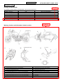
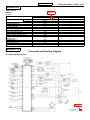
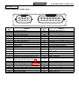
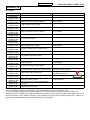
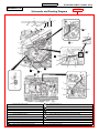
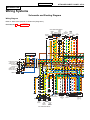
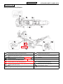
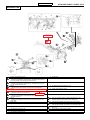
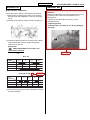
Service Bulletin
MOTORCYCLE
DATE
: Mar. 15, 2013
PAGE
: 1 OF 1
SUBJECT
: YEARLY CHANGE MODEL INFORMATION
APPLICABLE MODEL
: DL650A/UEL3
EFFECTIVE ENGINE OR FRAME NO. : DL650AL3
DL650AUEL3
REFERENCE
E21
E24
E28 and 33
E38
E99
E21
JS1C7111100109726 –
JS1C7111200100962 –
JS1VP56A D2100001 –
JS1VP56A D2100001 –
JS1C71213D0100001 –
JS1C7211100100090 –
: E21, 24, 28, 33, 38 and 99
This bulletin is to inform you of the service information for the above models.
When you service above models, please refer to the following service manuals. Please note, however,
that the contents indicated below in such manuals should be replaced by those in the attached sheet.
AFFECTED SERVICE MANUAL
MANUAL NAME
DL650A SERVICE MANUAL (BOOK):
MANUAL NUMBER
99500-36220-01E
CORRESPONDING PAGE
Page 0A-7, 0A-8, 0C-5, 1A-5,
1A-6, 1A-22, 1H-4, 9A-1,
9A-7, 9A-8, 9C-9, 9D-8
DL650A SERVICE MANUAL (CD-ROM): 99560-36220-018
We believe that this information will be useful in your service activities.
CONTENTS
Country and Area codes ................................................................. ATTACHED SHEET: PAGE 1
Warning, Caution and Information Labels Location .................... ATTACHED SHEET: PAGE 1
Service Data ..................................................................................... ATTACHED SHEET: PAGE 2
FI System Wiring Diagram .............................................................. ATTACHED SHEET: PAGE 2
Terminal Alignment of ECM Coupler ............................................. ATTACHED SHEET: PAGE 3
DTC Table......................................................................................... ATTACHED SHEET: PAGE 4
Fuel Tank Drain Hose and Breather Hose Routing Diagram....... ATTACHED SHEET: PAGE 5
No Spark or Poor Spark .................................................................. ATTACHED SHEET: PAGE 6
Wiring Diagram ................................................................................ ATTACHED SHEET: PAGE 7
Wiring Harness Routing Diagram .................................................. ATTACHED SHEET: PAGE 8
Ignition Switch Inspection .............................................................. ATTACHED SHEET: PAGE 10
Fuel Tank Side Cover and Fuel Tank Front Cover ....................... ATTACHED SHEET: PAGE 10
99500-36220-01E
ATTACHED SHEET: PAGE 1 OF 10
Section 0A
Country and Area Codes
ADDED
The following codes stand for the applicable country(-ies) and area(-s).
Code
Country or Area
DL650A L3 (E-21)
E.U.
DL650AUE L3 (E-21)
E.U.
DL650A L3 (E-24)
Australia
DL650A L3 (E-28)
Canada
DL650A L3 (E-33)
California (U.S.A)
DL650A L3 (E-38)
Taiwan
DL650A L3 (E-99)
Except the above Country or area
Effective Frame No.
JS1C7111100100726 –
JS1C7211100100090 –
JS1C7111200100962 –
JS1VP56A D2100001 –
JS1VP56A D2100001 –
E38 JS1VP56A D2100001 –
E99 JS1C71213 D0100001 –
UPDATED
Warning, Caution and Information Labels Location
7
2
10 (For E-21)
6
9
13
10 (For E-21)
8
1, 3
10 (Except for E-28)
11, 12, 16
5
14
4
15
10 (For E-28)
1. Noise label (For E-03, 24, 33)
11. I.D. label (For E-21, 24)
2. Information label (For E-03, 28, 33, 99 (If equipped))
12. Safety plate (For E-03, 28, 33, 99 (if equipped))
3. ICES Canada label (For E-28)
13. Brake fluid information mark (For E-21)
4. Vacuum hose routing label (For E-33)
14. Brake approval mark (For E-21)
5. Manual notice label (For E-03, 33)
15. Radiator cap label (For E-21)
6. Tire information label (For E-03, 21, 24, 28, 33, 38, 99 (If equipped))
16. Manufacture label (For E-38, 99 (If equipped))
7. General warning label (For E-03, 21, 24, 28, 33, 38, 99 (If equipped))
[A]: Rear front fender
8. Rear carrier warning label (For E-03, 21, 24, 28, 33, 38, 99 (If equipped))
[B]: Meter panel
9. Steering warning label (For E-03, 21, 24, 28, 33, 38, 99 (If equipped))
10. Screen label (For E-03, 21, 24, 28, 33, 38, 99 (If equipped))
[C]: Frame (RH)
[D]: Radiator cap
99500-36220-01E
ATTACHED SHEET: PAGE 2 OF 10
Section 0C
Service Data
ADDED
Wattage
Unit: W
Item
Headlight
HI
LO
Position/Parking light
Brake light/Taillight
Turn signal light
License plate light
Speedometer light
Tachometer light
Turn signal indicator light
High beam indicator light
Neutral position indicator light
Oil pressure/Engine coolant temp
indicator light
FI indicator light
Freeze indicator light
ABS indicator light
Immobilizer indicator light
Section 1A
E03, 28, 33, 38, 99
60 x 2
55 x 2
5x2
21/5
21 x 4
5
LCD
LED
LED
LED
LED
Specification
E21, 24
←
←
←
←
←
←
←
←
←
←
←
LED
←
LED
LED
LED
—
←
←
←
LED
Schematic and Routing Diagram
FI System Wiring Diagram
ADDED
, 38
, 38, 99
99500-36220-01E
ATTACHED SHEET: PAGE 3 OF 10
Section 1A
Terminal Alignment of ECM Coupler
TERMINAL
NO.
1
2
3
4
5
6
7
8
9
10
11
12
13
14
15
16
17
18
19
20
21
22
23
24
25
26
CIRCUIT
GP switch signal (GP)
IAT sensor signal (IAT)
IAP sensor signal #1 (IAP.F)
STP sensor signal (STP)
Power source for sensors (VCC)
HO2 sensor signal (HO2S)
Clutch lever position switch (CLT)
CKP sensor signal (CKP–)
Power source for fuel injector (VM)
Power source for back-up
Power source
Sensor ground (E2)
ECM ground (E1)
—
—
—
Immobilizer communication (for E-21, 24)
Immobilizer indicator (for E-21, 24) / Ignition
switch signal (for E-03, 28, 33, 38, 99)
ECT sensor signal (ECT)
TO sensor signal (TOS)
ADDED
TP sensor signal (TP)
IAP sensor signal #2 (IAP.R)
—
Cooling fan relay
Starter switch signal
Neutral switch signal
TERMINAL
NO.
27
28
29
30
31
32
33
34
35
36
37
38
39
40
41
42
43
44
45
46
47
48
49
50
51
52
CIRCUIT
CKP sensor signal (CKP+)
—
—
—
Serial data for speedometer (TECH)
Serial data for self-diagnosis
—
Immobilizer communication (for E-21, 24)
STVA signal (STVA. 1B)
STVA signal (STVA. 2B)
HO2 sensor heater (HO2SH)
—
EVAP system purge control solenoid valve
(for E-33, 38)
Tachometer
Ground
Fuel injector #2 (R)
Ignition coil #2 (R)
STVA signal (STVA. 1A)
STVA signal (STVA. 2A)
Fuel pump relay (FP Relay)
—
—
—
Ground
Fuel injector #1 (F)
Ignition coil #1 (F)
99500-36220-01E
ATTACHED SHEET: PAGE 4 OF 10
Section 1A
DTC Table
Code
C00
C12 (P0335)
)(Page 1A-27)
C13 (P1750)
)(Page 1A-30)
C14 (P0120-H/L)
)(Page 1A-33)
C15 (P0115-H/L)
)(Page 1A-39)
C17 (P0105)
)(Page 1A-30)
C21 (P0110-H/L)
)(Page 1A-43)
C23 (P1651-H/L)
)(Page 1A-47)
C24 (P0351)
)(Page 1A-52)
C25 (P0352)
)(Page 1A-52)
C28 (P1655)
)(Page 1A-52)
C29 (P1654-H/L)
)(Page 1A-56)
C31 (P0705)
)(Page 1A-63)
C32 (P0201)
)(Page 1A-66)
C33 (P0202)
)(Page 1A-66)
C40 (P0505)
)(Page 1A-68)
C41 (P0230)
)(Page 1A-70)
C42 (P1650)
)(Page 1A-73)
C44 (P0130/P0135)
)(Page 1A-73)
C60 (P0480)
)(Page 1A-78)
C62 (P0443)
)(Page 1A-82)
C65 (P0506/P0507)
)(Page 1A-85)
Malfunction Part
Remarks
None
No defective part
Crankshaft position sensor (CKPS)
Pick-up coil signal, signal generator
Intake air pressure sensor #2 (IAPS)
For #2 cylinder
Throttle position sensor (TPS)
*1
Engine coolant temperature sensor (ECTS)
Intake air pressure sensor #1 (IAPS)
For #1 cylinder
Intake air temperature sensor (IATS)
Tip-over sensor (TOS)
Ignition signal #1 (IG coil #1)
For #1 cylinder
Ignition signal #2 (IG coil #2)
For #2 cylinder
Secondary throttle valve actuator (STVA)
Secondary throttle position sensor (STPS)
Gear position signal (GP switch)
Injector signal #1
For #1 cylinder
Injector signal #2
For #2 cylinder
Idle speed control valve (ISC valve)
Fuel pump control system (FP control system) Fuel pump, fuel pump relay
Ignition switch signal (Anti-theft)
Ignition switch for E-03, 28, 33, 38, 99
/immobilizer for E-21, 24
ADDED
Heated oxygen sensor (HO2S)
Cooling fan control system
Cooling fan relay
EVAP system purge control solenoid valve
(E-33 only)
Idle speed control system
In the LCD (DISPLAY) panel, the malfunction code is indicated from small code to large code.
*1 To get the proper signal from the throttle position sensor, the sensor basic position is indicated in the LCD
(DISPLAY) panel. The malfunction code is indicated in three digits. In front of the three digits, a line appears in any of
the three positions, upper, middle or lower line. If the indication is upper or lower line when engine rpm is 1 300 r/min,
slightly turn the throttle position sensor and bring the line to the middle.
99500-36220-01E
ATTACHED SHEET: PAGE 5 OF 10
Section 1G
ADDED
Schematic and Routing Diagram
Fuel Tank Drain Hose and Breather Hose Routing Diagram
8
5
6
7
“A”
“B”
5
“b” “c”
“F”
“H”
1
“G”
3
2
“I”
6
“J”
3
“a”
2
1
“C”
“E”
6
“D”
“A”
“K”
5
1
4
8
7
6
1. Fuel tank water drain hose No. 1
“D”: Align the tip of the hose.
The tip of the hose must not come to contact with the under cowling.
2. Fuel tank water drain hose No. 2
“E”: The hose must not come to contact with the exhaust pipe support tightening part.
3. Water drain joint
“F”: Pass the drain hose under the thermostat inlet connector.
4. Clamp
“G”: Pass the drain hose above the high-tension cord.
5. Fuel tank breather hose No. 1
“H”: White marking
6. Fuel tank breather hose No. 2
“I”: Clamp it within 10 mm more or less from the marked position.
Clamp the hose together with the starter motor lead wire.
7. Fuel tank breather hose No. 3
“J”: Connect the thinner side of water drain joint to the reservoir tank overflow hose.
8. Fuel tank breather joint
“K”: Pass the drain hose inside the fuel feed hose.
“A”: To the fuel tank
“a”: 30 ± 10°
“B”: Insert the tip of the hose to the bottom of tank nipple.
“b”: 30 ± 10 mm (1.2 ± 0.4 in)
“C”: Clamp it at the marked position of the hose.
“c”: 40 ± 10 mm (1.6 ± 0.4 in)
99500-36220-01E
ATTACHED SHEET: PAGE 6 OF 10
Section 1H
No Spark or Poor Spark
Step 5
Inspect the ignition coils. Refer to “Ignition Coil and
Plug Cap Inspection” (Page 1H-7).
Troubleshooting
NOTE
Check that the transmission is in neutral and
the engine stop switch is in the “RUN”
position. Grasp the clutch lever. Check that
the fuse is not blown and the battery is
fully-charged before diagnosing.
Step 1
Check the ignition system couplers for poor
connections.
Is there connection in the ignition system
couplers?
Yes
Go to Step 2.
No
Poor connection of couplers.
Step 2
Measure the battery voltage between input lead wires
(E-21, 24: O/G and B/W, E-03, 28, 33, 38, 99: O/W and
B/W) at the ECM with the ignition switch in the “ON”
position.
ADDED
Is the voltage OK?
Yes
Go to Step 3.
No
• Faulty ignition switch.
• Faulty turn signal / side-stand relay.
• Faulty engine stop switch.
• Broken wire harness or poor connection
of related circuit couplers.
Step 3
Measure the ignition coil primary peak voltage. Refer
to “Ignition Coil and Plug Cap Inspection” (Page 1H-7).
NOTE
This inspection method is applicable only
with the multi-circuit tester and the peak volt
adaptor.
Is the peak voltage OK?
Yes
Go to Step 4.
No
Go to Step 5.
Step 4
Inspect the spark plugs. Refer to “Spark Plug
Inspection and Cleaning” in Section 0B (Page 0B-9).
Is the spark plug OK?
Yes
Go to Step 5.
No
Faulty spark plugs.
Is the ignition coil OK?
Yes
Go to Step 6.
No
Faulty ignition coil.
Step 6
Measure the CKP sensor peak voltage and its
resistance. Refer to “CKP Sensor Inspection” (Page
1H-9).
NOTICE
The CKP sensor peak voltage inspection is
applicable only with the multi-circuit tester
and peak volt adaptor.
Are the peak voltage and resistance OK?
Yes
• Faulty ECM.
• Open or short circuit in wire harness.
• Poor connection of ignition wire
harness.
No
• Faulty CKP sensor.
• Metal particles or foreign material being
stuck on the CKP sensor and rotor tip.
99500-36220-01E
ATTACHED SHEET: PAGE 7 OF 10
Section 9A
Wiring Systems
Schematic and Routing Diagram
Wiring Diagram
Refer to “Wire Color Symbols” in Section 0A (Page 0A-7).
ADDED
For E-03, 28, 99
RIGHT HANDLEBAR SWITCH
B/O
B
Br
B/W
B/Br
Br/W
R
O
W/B
O/G
W/B
Y/B
O/W
R/W
Y/R
Y/R
B/W
R/B
G/Y
Y/R
B/W
Y/B
W
Gr
B
W
IGNITION
COIL #1
IGNITION
COIL #2
Br
B/W
O/B
O/W
B/R
B/Bl
Y/G
Y/W
O/R
OFF
ON
O/W
W/Bl
B/R
O
O/Y
O/G
Br
O/G
B/W
PUSH
O/B
O/W
O/G
W/B
Y/G
Y/Bl
O
OFF
RUN
ON
OFF
LOCK
P
R
O
O/Y
Gr
Br
IGNITION
SWITCH
REAR
OIL
BRAKE
PRESSURE
LIGHT
SWITCH
SWITCH
HO2
TO
FUEL
SENSOR
FUEL SENSOR
PUMP
PUMP
ON
OFF
OFF
RELAY
ON
M
O/W
B/Br
W/G
W/B
FRONT
ENGINE
BRAKE
STOP STARTER LIGHT
SWITCH BUTTON SWITCH
O
B/W
POSITION LIGHT (R)
Br
B/W
Br
B/W
FRONT TURN
SIGNNAL LIGHT (R)
Lg
B/W
Lg
B/W
Y
B/W
B/Bl
HEADLIGHT (R)
Y
B/W
HEADLIGHT (L)
Br/B
P/W
B/G
Bl
G/Y
Y/B
Y
Lg
Br
Bl/B
O/R
B/W
R/W
B
O/G
Gr
COMBINATION METER
Bl/B
Y/B
B/G
O/R
P/W
G/Y
Br/B
Gr
B
Lg
Br
O/G
R/W
O
B/W
Y
Br
B/Bl
Bl/B
Y/B
B/G
O/R
P/W
G/Y
Br/B
Gr
B
Lg
Br
O/G
R/W
O/Y
B/W
Y
Br
W
B/Bl
FRONT TURN
SIGNNAL LIGHT (L)
B
B/W
B
B/W
POSITION LIGHT (L)
Br
B/W
Br
B/W
Bl
B/W
HI
LO
PASS
OFF
ON
PUSH
SELECT
BUTTON
PUSH
L
PUSH
R
FREE
STP
IAP
SENSOR FUEL
SENSOR
COOLING
GP
STV
#1
FAN ACTVATOR INJECTOR
SWITCH
#1
FUEL
MOTOR
ECT
INJECTOR
SENSOR
#2
DIMMER
HAZARD
&
SWITCH
PASSING
HORN
SWITCH
BUTTON
CLUTCH
TURN
LEVER
SIGNAL
POSITION
SWITCH
SWITCH
LEFT HANDLEBAR SWITCH
4
5
6
1
2
3
G
O/Y
O/B
Br
Lbl
O/Y
O
O/G
B/R
O/R
Bl/B
Bl
B/R
W/Bl
Y/W
Y
W
R/W
B/Br
B/Bl
B/Br
G/B
R
Gr/B
Y/R
Gr/W
Y/R
R
Y
B/Br
B/Lg
P/W
G
W/B
Bl
P
B/W
Bl
P
B/W
HORN
B
Bl
COOLING
FAN
RELAY
B/W
Y/G
B/R
Dg
B/Bl
Bl
B/W
B/Y
W
B
Lbl
Lg
Y
O
B/Bl
O
B/W
Gr
Lg
B
B/Bl
Lbl
B/W
B/Y
W/Bl
B
Lbl
Lg
Y/W
Y/Bl
B/W
B
G/R
O/W
O/R
B
AMBIENT AIR TEMP SENSOR
FUSE BOX
1. HEAD HI
2. HEAD LO
3. FUEL
4. IGNITION
5. SIGNAL
6. FAN
15 A
15 A
10 A
10 A
15 A
15 A
99500-36220-01E
ATTACHED SHEET: PAGE 8 OF 10
Section 9A
Wiring Harness Routing Diagram
5
ADDED
1. Clamp
: Clamp the ignition coil lead wire and generator lead wire.
8. Clamp
: Clamp the reservoir tank inlet hose.
2. Clamp
: Clamp the starter motor lead wire, wire harness, rear brake light switch lead
wire and rear wheel speed sensor lead wire.
9. Clamp
: Clamp the wire harness and regulator/rectifier lead wires.
3. Clamp
: Clamp the wire harness.
ADDED
10. Fixed clamp
4. Clamp
: Clamp the wire harness and radiator inlet hose.
11. Speed sensor
5. Clamp
: Clamp the radiator hose, clutch cable and ignition coil.
12. Clamp
: Clamp the side-stand switch lead wires.
6. Clamp
: Clamp the side-stand switch lead wire. Set the clamp between the crankcase
and engine sprocket outer cover bolt.
“A”: Set the HO2 sensor lead wire coupler and ABS lead wire inside
the frame side cover and rear fender (rear).
7. Clamp
: Clamp the gear position switch lead wire, generator lead wire, side-stand
switch lead wire and speed sensor lead wire.
: 4.5 N·m (0.45 kgf-m, 3.3 lbf-ft)
99500-36220-01E
ATTACHED SHEET: PAGE 9 OF 10
Section 9A
17
16
21
19
9
9
18
20
2
ADDED
3
5
4
7
6
8
10 11 12
14 15
13
1. Ambient air temperature sensor
15. Clutch cable
2. Clamp
: Clamp the right handlebar switch lead wire, immobilizer lead wire (E-21,
24) at the gray tape point and ignition switch lead wire.
16. 10 terminals coupler of left handlebar lead wire
3. Clamp
: Clamp the right handlebar switch lead wire, immobilizer lead wire (E-21,
24) and ignition switch lead wire.
17. 4 terminals coupler of left handlebar lead wire
4. Clamp
: Clamp the stator motor lead wire and oil pressure switch lead wire.
18. Immobilizer lead wire coupler (E-21, 24)
5. Clamp
: Clamp the wiring harness and battery minus wire.
19. Ignition switch lead wire coupler
6. Clamp
: Clamp the oil pressure switch lead wire.
20. Right handlebar switch lead wire coupler
ADDED
7. Clamp
: Clamp the right handlebar switch lead wire and grommet sleeve on the
front brake hose No.1.
21. Front wheel speed sensor wire coupler
8. Clamp
: Clamp the left handlebar switch lead wire and grommet sleeve on the
clutch cable.
“A”: Pass the immobilizer lead wire, ignition switch lead wire, right
handlebar switch lead wire under the front brake pipes.
9. Fixed clamp
“B”: Pass the right handlebar switch lead wire through the guide.
10. Right handlebar switch lead wire
“C”: Pass the right handlebar switch lead wire in front of throttle cables.
Pass the right handlebar switch lead wire inside throttle cables.
11. Ignition switch lead wire
“D”: Pass the ignition switch lead wire in front of immobilizer lead wire
(E-21, 24).
12. Immobilizer lead wire (E-21, 24)
“E”: Do not twist the ignition switch lead wire.
13. Throttle cable
“F”: Pass the left handlebar switch lead wire through the guide.
14. Left handlebar switch lead wire
99500-36220-01E
Section 9C
ATTACHED SHEET: PAGE 10 OF 10
Section 9D
Ignition Switch Inspection
Inspect the ignition switch in the following procedures:
1) Remove the air cleaner box. Refer to “Air Cleaner
Box Removal and Installation” in Section 1D (Page
1D-6).
2) Disconnect the ignition switch lead wire coupler (1).
Fuel Tank Side Cover and Fuel Tank Front Cover
Installation
Install the fuel tank side cover and fuel tank front cover in
the reverse order of removal. Pay attention to the
following point:
• Tighten the fuel tank side cover bolt (1) to the
specified torque.
Tightening torque
Fuel tank side cover bolt (a): 5.5 N·m (0.55 kgf-m,
4.0 lbf-ft)
1
(a)
3) Inspect the ignition switch for continuity with a tester.
If any abnormality is found, replace the ignition
switch with a new one.
Special tool
: 09900–25008 (Multi circuit tester set)
Tester knob indication
Continuity (
)
ADDED
E-21, 24
Position
Color
R
O
Gr
Br
ON
OFF
LOCK
P
ADDED
E-03, 28, 33, 38, 99
Position
Color
R
O
O/Y
Gr
Br
ON
OFF
LOCK
P
4) After finishing the ignition switch inspection, reinstall
the removed parts.