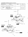
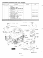
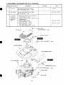
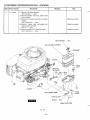
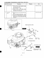
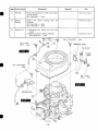
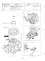
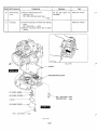
1
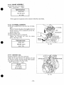
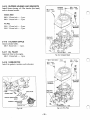
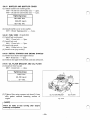
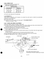
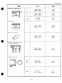
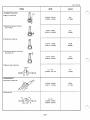
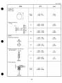
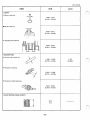
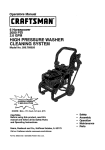
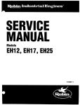
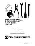
SERVICE
MANUAL
IVIodel
EH18V OHV
396S322
ROBIN AMERICA, INC.
ROBIN TO WISCONSIN ROBIN
ENGINE MODEL CROSS REFERENCE LIST
WISCONSIN ROBIN
ROBIN
0
SIDE VALVE
W 1-080
W1-145
W1-145V
W1-185
W1-185V
W1-230
W 1-280
W 1-340
W 1-390
Wl-45OV
EY21W
EY44W
EY18-3W
EY25W
EY27W
EY08
EY15
EY 15V
EY20
EY2OV
EY23
EY28
EY3 5
EY40 EY45V
EY2 1
EY44
EY 18-3
EY25
EY27
OVERHEAD VALVE
WO1-115
wo1-120
WO1-150
WO1-170
wo1-210
WOl-250
WO 1-300
WO1-300V
WO1-340
WO 1-340V
WO 1-43
OV
EH11
EH12
EH15
EH17
EH21
EH25
EH30
EH30V
EH34
EH34V
EH43V
0
TWO CYCLE
WT1-125V
EC13V
DIESEL
DY23
DY27
DY30
DY35
DY4 1
WRD 1-230
WRD 1-270
-1-300
WRD1-350
WRD1-410
0
CONTENTS
.
Title
Section
1. SpEClF[CATlONS .........................................................................................
2. PERFORMANCE............................................................................................
2-1
Maximum Output ....................................................................................
Page
1
2
2
2-2 Maximum Torque ...................................................................................
2
2-3 PerformanceCurves ............................................................................... 2
3 FEATURES ................................................................................................... 3
.
4.GENERAL DESCRIPTION OF ENGINE COMPONENTS
4-1
4-2
4-3
.................................
3
4-4
4-5
4-6
4-7
4-8
4-9
4-10
4-1 1
4-12
4-13
4-14
4-15
5 . DISASSEMBLY AND REASSEMBLY............................................................
5-1 PreparationsandSuggestions .................................................................. .
5-2 Special Tools.......................................................................................
5-3 DisassemblyProcedures ........................................................................
5-4 ReassemblyProcedures .........................................................................
5-5 Break-inOperation ...............................................................................
6. MAGNETO..................................................................................................
6-1Flywheel
Magneto ................................................................................
11
11
11
12
27
40
41
Basic The0ry .......................................................................................
41
41
6-3 WiringDiagram ....................................................................................
42
6-2
7.AUTOMATlC DECOMPRESSlON SYSTEM ..................................................
43
8.CARBURETOR ........................................................................................... 44
.
8-1 Operation and Construction ....................................................................
44
8-2 DisassemblyandReassembly .................................................................
45
9 STARTING SYSTEM ................................................................................... 47
9-1Recoil
Starter ........................................................................................
47
.
Section
Title
Page
10. TROUBLESHOOTlNG ..............................................................................
51
10-1 Starting Difficulties................................................................................
51
10-2 Engine Misfires ....................................................................................
52
10-3 Engine Stops.......................................................................................
52
10-4 Engine Overheats.................................................................................
52
10-5 Engine Knocks.....................................................................................
53
10-6 Engine BacMires Through Carburetor........................................................
53
11. lNSTALMTlON ....................................................................................... 54
11-1 Installing.............................................................................................
54
11-2 Ventilation ..........................................................................................
54
11-3 Exhaust Gas Discharge .........................................................................
54
12. SERVICE DATA ......................................................................................
55
12-1 Clearance Data and Limits ...................................................................... 55
12-2 Torque Specifications............................................................................
61
12-3 Oil Grade Chart....................................................................................
61
62
13. MAINTENANCE AND STORAGE .............................................................
13-1 Daily Maintenance (Every 8 Hours)............................................................
13-2 Initial 20 Hours Maintenance ...................................................................
62
13-3 Every 50 Hours (10 Days) Maintenance.....................................................
62
13-4 Every 100-200 Hours (Monthly) Maintenance .............................................
63
62
63
13-5 Every 500-600 Hours Maintenance ..........................................................
13-6 Every 1000 Hours (Yearly) Maintenance ....................................................
63
13-7 Engine Storage ....................................................................................
63
..
1. SPECIFICATIONS
EH18V
Model
Air-Cooled, 4-Cycle, Vertical Shaft, Overhead Valve, Gasoline Engine
TY Pe
67 X 52 mm
(2.64 X 2.05in.)
Bore X Stroke
183 cc
(11.16 c,u.in.)
Piston Displacement
4.4 /3600 KW/ rpm
(6/3600 HP/rpm)
Maximum Horsepower
1.29/ 2700 kg-m / rpm
(9.3/2700 ft. Ibs/rpm)
Maximum Torque
~
~
~~~~
Counterclockwise As Viewd From PTO Shaft Side
Rotation
Cooling
'
'
Forced Air Cooling
~
Oil Pump Type
Lubrication
Automobile Oil SAE #20, #30or 1OW-30
Lubricant
Horizontal Draft Type
Carburetor
I
Fuel
Automobile Gasoline
Fuel Feed
~
~~
Gravity Type
~
~~
Governor System
Centrifugal FlyweightType
Ignition System
Flywheel Magneto (Solid State)
Spark Plug
CHAMPION L86C
Starting System
Recoil Starter
Dry Weight
Dimensions Without
P.T.0 Shaft
LXWXH
17 kg (37.5Ibs.)
409 X 372 x 31 1 mm (16.10 X 14.65 x 12.24 in.)
Specifications and dimensions are subject to change without notice.
- 1 -
2. PERFORMANCE
2-1 MAXIMUMOUTPUT
The maximum output of an engine is such a standard power as produced by the engine with its throttle
valvefullyopenedafteritsinitialbreak-inperiodwhenallthemovingpartsareproperlywornin.
Therefore, a new engine may not produce the maximum output in the beginning because the moving
parts are not in a properly worn-in condition.
2-2 MAXIMUMTORQUE
The maximum torque indicates the torque at the output shaft when the engine is producing the maximum
output.
2-3 PERFORMANCECURVES
EH18V
5.2;
(7.0
Tn"--r
""_~_
4.41
(6.0
"""
"""_
"
"
"
7.4!
(2.0
2000
2400
2800
3200
REVOLUTlON
-
3600
"i
r.p.m
-2-
3. FEATURES
1. Theoverheadvalvedesignofferscompactness,lightweightandidealcombustioncharacteristics
resulting in more power from less fuel and prolonged engine life.
2. The parts such as a large capacity muffler, dual element air cleaner reduce noiseto a minimum level.
3. The automatic decompression system offers easy and sure starting.
4. The muffler and carburetor are located
on opposite sides, making the arrangements for cooling air
flow much easier in the designof power equipment.
5. The oilpumpandoilfilterprovideexcellentlubricationregardless
of enginepostureduring
operation.
6 . This engine is offered in two stylish versions.
7. The Pro-Poly version engine is covered witha stylishly designed shroud with the
fuel tank incoroprated intoit.
'8. The Classic Steel version does not have the shroud or combined fuel tank.
4. GENERALDESCRIPTION OF ENGINECOMPONENTS
4-1 CYLINDER AND CRANKCASE
Thecylinderandcrankcaseissinglepiecealuminumdiecasting.Thecylinderliner,made
of
specialcastiron,ismoldedintothealuminum
casting.
Thecrankcasehasamountingsurface
on the
output shaft side, where the main bearing cover is
attached. (See Fig. 4-1.)
Fig. 4-1
4-2 MAIN BEARING COVER
The main bearing cover is an aluminum
diecasting, which is mounted on the output shaft
side of the crankcase. Remove the main bearing
cover to inspect inside of the engine.
The main bearing cover also functions as an oil
pan, with,a trochoid oil pump and oil filler.
(See Fig. 4-2.)
. .
Fig. 4-2
-3-
n.
4-3 CRANKSHAFT
Thecrankshaftisaforgedcarbonsteel,andthe
crank pin is induction-hardened. The PTO end
theshafthasacrankshaftgearwhichispressed
into
Fig. 4-3.)
r,
of
CRANKSHAFT GEAR
Fig. 4-3
4 4 CONNECTING ROD ANDPISTON
Theconnectingrod
is aforgedaluminumalloy,
and its large and small ends function as bearings.
The piston is analuminumalloycasting,and
Fig. 4-4
4-5 CAMSHAFT
Thecamshaft isa hollowshaped and made of
specialcast iron withthecamshaftgearcasted
together.
A centrifugal decompression lever is assembled on
the camshaft. The lubrication oil
pump isdriven
by the groove on the end of the camshaft.
(See Fig. 4-5.)
Fig. 4-5
-4-
4-6 VALVEARRANGEMENT
'
The intake valve is located at flywheel side of the
cylinder
head.
Hard alloy valve seats are molded
in the cylinder
head and stellite is fused to the exhaust valve face.
The cylinder baffle leads cooling air to the exhaust
valve area for the optimum cooling.
(See Fig. 4-6.)
II
EXHAUST V i
Fig. 4-6
4-7 CYLINDER HEAD
Thecylinderhead,isanaluminumdiecasting,.
which utilizes wedge type combustion chamber for
the highest combustion efficiency.
(See Fig. 4-7.)
Fig. 4-7
4-8 GOVERNORSYSTEM
The governor is a centrifugal flyweight type which
ensuresconstantoperationattheselectedspeed
against load variations.
Thegovernorgearwithgovernorweightsis
installedonthebearingcoveranddriven
by' the
camshaft gear. (See Fig.4-8.)
Fig. 4-8
-5-
n
4-9 COOLING SYSTEM
The large fins on the flywheel provide sufficient cooling air capacity for the inlet and exhaust area and
cylinder.
The cylinder baffle helps the cooling air flow efficiently.
4-1 0 LUBRICATION
EH18V has a trochoid pump outside the main bearing cover that is driven by the camshaft.
EH18V uses forced splash type lubrication. (See Fig. 4-9.)
/ CAMSHAFT
M6 FLANGE BOLT ... 1pce.
OIL SHELTER PLATE
M,AIN BEARING COVER
OIL PUMP COVER
&Fig. 4-9
-6-
M6 FLANGE BOLT ... 4pcs.
4-1 1 IGNITION SYSTEM
The ignition
system
is transistor
a
controlled
magneto ignition system which consists
of a flywheel and an ignition coil with a built in transistor
mounted on the crankcase.
Thissystemhasanautomaticignitiontiming
advancing for easier starting. (See Fig.4-10.)
For details, refer to page 39, section 6.
4-12 CARBURETOR
The engines are equipped with a horizontal draft
carburetor that has a float controlled
fuel system
and a fixed main jet.
Thecarburetorsarecalibratedcarefullyforthe
surestarting,
good acceleration,lowfuelconsumption and sufficient output.
Forthe-datails,refer
t o page42,section
“8
CARBURETOR”. (See Fig. 4-11.)
Fig. 4-1 1
4-13 AIR CLEANER
.
The air-cleaner is aheavy-dutytypewithadual
elementsystem.(See Fig. 4-12.)
WING BOLT
GROMMET
I
;
’<
CLEANERCOVER
eo
PRIMARY ELEMENT
#(URETHANE
FOAM)
.’: .
.’
J
SECONDARY ELEMENT
PAPER ELEMENT)
(PAPER
Fig. 4-12
-7-
4-14 DECOMPRESSION SYSTEM
An automaticdecompressionmechanismwhich
opensexhaustvalve
before thepistonreaches
compression top is assembled on the camshaft for
easy starting. (See Fig. 4-13)
For details, refer to page 41, section 7.
[
AUTOMATIC DECOMPRESSION SYSTEM
&$
RETURN SPRING
-a-
n
4-15 SECTIONAL VIEW
OF ENGINE
BLOWER HOUSING
RECOIL STARTER
I
\
COVER
MAIN BEARING
CRANKSHAFT
-9-
SPARK PLUG
CONNECTING ROD
MUFFLER
- 10
-
5. DISASSEMBLY AND REASSEMBLY
5-1 PREPARATIONS
AND
SUGGESTIONS
1) When disassembling the engine, remember the locations of the individual parts so that they can be
reassembledcorrectly. If youareuncertain of identifying some parts, it issuggestedthattags
attached to them.
Have boxes ready to keep disassembled parts
by group.
To prevent missing and misplacing, temporarily assemble each groupof disassembled parts.
Carefully handle disassembled parts, and clean them with oil if necessary.
Use the correct toolsin the correct way.
be
5-2 SPECIAL TOOLS
I
Tool No.
I
I
Tool
Use
I
228- 95003-07
I
Piston ring compressor
I
For placing piston ring
I
Market parts
I
Flywheel puller
1
For pulling off the flywheel
PISTON RING COMPRESSOR
/
/
FLYWHEEL PULLER
Fig. 5-1
-
11 -
I
I
I
5-3 DISASSEMBLY PROCEDURES (CLASSIC STEEL)/ (PRO POLY)
I
I
Step Part
remove
to
'I
Spark plug
II
Oil drain, oil
filter and
bracket
~~
~~
I
Procedures
Remarks
(1) Remove oil gauge.
(2) Remove oil drain plug and drain oil.
(3) Remove oil filter.
(4)Remove oil filter bracket.
M6X 12mm bolt
2pcs.
14mm box wrench
lOmm box wrench
....
OILGAUGE
T
p
SPARK
OILGAUGE
-
T
y
OIL FILTER BRACKET '
OIL DRAIN PLUG
mm
SPARKPLUG
Tool
19mm plug wrench
Remove spark plug cap and spark plug.
PLUG
I
,'
LTER
~ A c
Clni
r ... gnrc
'
OIL DRAIN PLUG
OIL FILTER
BRACKET
Fig. 5-2
- 12-
M6 BOLT '.. 2 p C ~ .
5-3 DISASSEMBLY PROCEDURES (CLASSIC STEEL) -CONTINUED
Part to remove
Recoil starter
Procedures
Remove recoil starter from the engine.
M6X8mm bolt
4pcs.
lOmm box wrench
- 0 . .
Fuel tank
(1) Remove fuel tank.
M6X 12mm bolt . - * * 2pcs.
(2) Remove fuel pipe from the fuel
tank.
(3) Remove side guard.
M6 X 12mm bolt *
Zpcs.
(4) Remove bracket (fuel tank)
lpce.
M6X 14mm bolt
( 5 ) Remove cover (stop switch).
-
....
RECOIL STARTER ASS’Y
M6 FL
M6 FLANGE
BOLT GPCS.
- 8 -
COVER (stop switch)
HOSE CLAMP
I.
SIDE GUARD
M6 FLANGE BOLT ... 1pce.
Fig.
- 13’
-’
5-3
5-3 DISASSEMBLY PROCEDURES (CLASSIC STEEL) -CONTINUED
-
Step Part to remove
Procedures
5
Air cleaner
Remarks
(1) Remove air cleaner cover and air cleaner
element
M6 wing bolt * * - - lpce.
(2) Remove breather hose from cleaner base
and crankcase.
(3) Remove air cleaner base from air cleaner
bracket.
M6X12mm bolt
Ipce.
(4) Removecleaner
baseand
gasket (air
cleaner) from carburetor.
M6 nut
2pcs.
(5) Remove bracket (A/C) from the engine.
M6X 12mm bolt
lpce.
(6) Remove bracket ( N C cover)
M6 X 14mm bolt
1pce.
M6x 14mm tapping bolt
lpce.
Tool
lOmm box wrench
.--.
lOmm box wrench
....
lOmm box wrench
....
-
lOmm box wrench
- ....
PROCEED TO STEP7 OF DISASSEMBLY PROCEDURES
M6 WING BOLT ... Ipce.
M6
X
14mm BOLT ... lpce.
AIR CLEANER COVER
AIR CLEANER
M6 x 14mm
AIR CLEANER BASE
HOSE CLAMP
M6 NUT ... ~ P C S .
BREATHER HOSE
Fig. 5-4
- 14-
5-3 DISASSEMBLY PROCEDURES (PRO POLY)-CONTINUED
Tool
Remarks
Procedures
Step Part to remove
3
Top cover
Remove top cover fromthe engine.
MSX 16mm tapping screw
2pcs.
(+) driver
4
Recoil starter
Remove recoil starter from the engine.
M6 X 12mm bolt
4pcs.
lOmm box wrench
5
(1) Remove air cleaner coverand element
Air cleaner
M6 wing bolt
1pce.
cover and
engine shroud (2) Remove fuel pipe from the fuel tank
(engine shroud).
(with fuel
(3) Remove engine shroud.
tank)
lpce.
M6X 12mm bolt
(4)Remove bracket ( N C cover)
M6X14mm bolt
lpce.
M6X
14mm
tapping
bolt
lpce.
..
----
9 0 . -
L
SCREW
TAPPING
TOP COVER
lOmm box wrench
....
lOmm box wrench
....
I
.
... ~ P C S .
RECOIL STARTER
X
12mm BOLT . . . 4pcs.
-
AIR CLEANER COVER
M6 X 14mm BOLT ... lpce.
BRACKET (A/C cover)
m TAPPING BOLT... 1pce.
- 15-
5-3 DISASSEMBLY PROCEDURES (PRO POLY)-CONTINUED
-
Step Part to remove
Procedures
6
Air cleaner
Tool
Remarks
r:
(1) Remove air cleaner element
....
lpce.
M6 wing bolt
(2) Remove breather hose from cleaner base
and crankcase.
(3) Remove air cleaner base from air-cleaner
bracket.
M6X12mm bolt
lpce.
(4) Removecleanerbase
and gasket (air
cleaner) from carburetor.
M6 nut
2pcs.
( 5 ) Remove bracket (AK) from the engine.
lpce.
M6X12mm bolt
lOmm box wrench
----
lOmm box wrench
--
lOmm box wrench
....
M6 WING BOLT
AIR CLEANERELEMENT
Fig. 5-4
- 16-
\
' 1 .
1pce.
5-3 DISASSEMBLY PROCEDURES (CLASSIC STEEL)
/ (PRO POLY)
Remarks
Step
'art to remove
Procedures
7
Speed control
(1) Remove speed control assembly from the
Tool
lOmm box wrench
crank case, then remove governor spring
from the governor lever.
M6X 12mm bolt
2pcs.
(2) Removechoke rod fromspeed control
assembly,thenremovechoke
rod from
choke shaft of the carburetor.
.-..
8
Governor
lever
lOmm box wrench
(1) Remove governor lever fromthe governor
shaft.
M6 X 25mm bolt and washer assy
1pce.
(2) Remove rod spring and governor rod from
governorlever,thenremove
rod spring
and governor rod from throttle shaft of the
carburetor.
-- -
r
SPEED CONTROL LEVER
\
W
Fig. 5-6
Fig. 5-5
- 17-
'
Dart to remove
Remarks
Procedures
Carburetor
(1) Remove carburetor from stud bolts.
(2) Removegasket and insulator from stud
bolts.
Muffler
( I ) Remove muffler cover from muffler.
M5X lOmm tapping screw
3pcs.
(2) Remove muffler and gasket. (muffler)
M8 X70rnm bolt andwasher assy
....
Tool
(+) driver
12mm box wrench
-*..Zpcs.
M8 X 16mm bolt andwasher assy
.*.-lpce.
M5 x 10mm TAPPING SCREW ... 3pcs.
\
MUFFLER COVER
I
M8 x 16mm BOLT AND
CARBURETOR
Fig. 5-7
- 18-
Step Part to remove
11
Remarks
Procedures
Tool
Remove the clamp from oil filler, and remove
oil filler bracket.
M 6 X 12mm bolt
Ipce.
I O m m box wrench
Blower
hausing
Remove the blower
housing
crankcase.
M6x 12mm bolt
2pcs.
M 6 X 14mm bolt
lpce.
lOmm box wrench
Ignition coil
(1) Disconnectstopswitchwire
from stop
switch.
(2) Remove ignition coil from crankcase.
M6 X 30mm bolt
2pcs.
Oil filler
--
12
13
from
the
....
....
--
- e
- 19-
lOmm box wrench
I
Part to remove
I
Flywheel
I
Procedures
Remarks
I
( 1 ) Remove starter pully from flywheel
MI4 n u t
Ipce.
(2) Remove flywheel from crankshaft.
(See Fig. 5-1 1.)
18mm box wrench
(3) Remove key from crankshaft.
(-) driver
I
e
M14 NUT '.. lpce.
STARTER PULLEY
Fl
Tool
&
Fig. 5-10
KEY
\
Fig. 5-9
Fig. 5-12
-20-
I
Step Part to remove
15
Brake assy
Remarks
Procedures
(1) Remove brake assy.
M6 X 12mm bolt
--
TooI
lOmm box wrench
4pcs.
M6 x 12mm BOLT ... 4pcs.
BRAKE ASSY
\
Fig. 5-13
-21
-
Step Part to remove
16
Cylinder
Cylinder
head
Remarks
Tool
1Omm box wrench
(1) Remove cylinder baffle.
M6X8mm bolt
17
Procedures
*.--
lpce.
(1) Removerockercover
and guide plate
from cylinder head.
M6 X 12mm bolt
4pcs.
(2) Loosen lock nut for rocker arm adjusting
screw.
M8 lock nut
2pcs.
(3) Slide off rocker arm shaft from the holder
to the flywheel side, remove rocker arms.
(See Fig. 5-1 5 . )
(4)Remove push rods.
(5) Remove cylinder head and gasket.
M8X65rnm bolt
2pcs.
M8X40mm bolt . - - lpce.
M8 flangenut
1pce.
lOmm box wrench
12mm box wrench
-
12mm box wrench
-....
Fig. 5-14
Fig. 5-15
-22-
Step
-
'art to remove
Remarks
Procedures
18
Intake and
(1) Press down spring retainer and slide it to
exhaust valve
release from the groove of valvestem,
then removespring
retainer andvalve
spring. (See Fig. 5-16.)
(2) Remove intake andexhaustvalves from
cylinder head.
19
Breather
Clean
carbon
and
gum
deposits from the valves,
valve
seats,
ports and
guides.
Inspect
valves,
valve seats and guides.
(1) Remove breather cover.
M6 X 12mm bolt
2pcs.
Remove gasket (tappet cover), breather
plate and gasket (breatherplate).
lOmm box wrench
.
-
Tool
INTAKE VALVE
EXHAUST VALVE
I
I
M6 x 12mm BOLT
Fig. 5-17
VALVE SPRING
\\
RETAINER
COLLET
Fig. 5-16
-23 -
... 2pcs. /
Part to remove
Mainbearing
(See
cover
Procedures
Remarks
Fig. 5-18.)
M6X30mm bolt and washer assy
* e * .
Oil pump
Do not lose spacer for
crankshaft.
(1) Remove mainbearing cover.
cover.
M6 X 12mm bolt
4pcs.
(2) Remove oil pump(Inner) and oil pump
(Outer).
-
fi
I
M6 x 12mm BOLT
'.'
lOmm boxwrench
8 ~ ~ s .
(1) Remove oil pumpcoverfrom main bearing
OIL PUMP COVER
Tool
4pcs.
Fig. 5-1 9
-24
-
lOmm box wrench
B
Step Part to remove
22
Camshaft and
tappets
1
Procedures
Tool
Remarks
(1) Remove camshaft from crankcase.
(See Fig. 5-20.)
To prevent the tappets
from getting damages, put
the crankcase
cylinder
side down.
(See Fig.5-20.)
Tappet must be installed
in their original position.
Mark tappets prior to removal to prevent error.
(2) Remove tappets from crankcase.
-
/,
/,
I
,/'
f
CAMSHAFT
I
TAPPET
I
/'
I
I
Fig. 5-20
-25-
I
Step Part to remove
23
I
Procedures
(1) Remove
connecting
rod bolts and
connecting rod cap.
Connecting rod bolt
2pcs.
(2) Turn crankshaft until piston is at top dead
center, push out connecting rod and piston
assembly through top of cylinder.
(3) Remove clips and piston pin to remove
connecting rod from piston.
(4)Remove piston rings from piston.
L
24
I
I
I
Connecting
rod and
piston
Crankshaft
Tool
Remarks
I
Scrape
off
all
carbon
might
deposits
that
interfere with removal of
piston from upper end of
cylinder.
lOmm box wrench
Ring expander
(l).Tap lightly on flywheel end of crankshaft
to remove from crankcase. (See Fig.5-22.)
M
0
W
\
CONNECTING ROD CAP
SPACER
f-
Fig. 5-22
Fig. 5-23
-26-
5-4 REASSEMBLYPROCEDURES
0 PRECAUTIONS .FOR REASSEMBLY
1) Clean parts thoroughly’before reassembly.
Pay utmost attention to cleanliness of piston, cylinder, crankshaft, connectingrod and bearings.
2) Scrape off all carbon deposits from cylinder head, piston top and piston ring grooves.
3) Check lip of oil seals. Replace oil seal if the lip is damaged.
Apply oil to the lip before reassembly.
4) Replace all the gaskets with new ones.
5) Replace keys, pins, bolts, nuts, etc., if necessary.
6) Torque bolts and nuts to specification referring to page59 “12-2 TORQUE SPECIFICATIONS”
7 ) Apply oil to rotating and sliding portions.
8) Check and adjust clearances and end plays where specified in this manual.
5-4-1 CRANKSHAFT
(1) Installcrankshaftoncrankcaseusinganoil
sealguidetoavoiddamagetocrankshaft
seal. (See Fig. 5-24.)
oil
Fig. 5-24
-27
-
5-4-2 PISTONANDPISTONRINGS
(1) Install oil ring first, then second ring and top
ring. Spread ring only far enough
to slip over
piston and into correct groove. Use care not
to
distort ring. (See Fig. 5-26.)
Fig. 5-25
EN ENDS OF PI
Fig. 5-26
5-4-3 PISTONANDCONNECTINGROD
Install piston on connection rod.
Oil the small end of connecting rod before installing piston and piston pin.
Use clips on both side of the piston pin to secure
piston pin in position.
Fig. 5-27
-28-
5-4-4
CONNECTING ROD
(1) Before installing the piston and connecting rod
in the cylinder, oil the piston, piston rings and
cylinder wall.
(2) Stagger the piston ring gaps
90” apart around
the piston. (See Fig. 5-28.)
Useapistonringcompressorwheninstalling
piston.
Install piston and rod with the “MA” marks on
flywheel side of the crankcase.
(See Fig. 29.)
(3) Turn crankshaft to bottom dead center, then tap
lightly top of the piston until large end
of the
connecting rod meets crank pin.
Fig. 5-28
PISTON RING COMPRESSOR
CONNECTING ROD
CRANKCASE
Fig. 5-29
(4)Install connecting rod cap with the match mark
on themainbearingcoverside.(Matchthis
markwiththeone
on theleftside
of connectingrod’slargeendviewedfrommain
bearing cover side.) (See Fig. 30)
Connecting rod bolt
2 pcs.
- 0 . -
Tightening torque
17-20 N*m
170-200 kg-cm
12.2-14.5 ft4b
Fig. 5-30
Checkforfreemovemont
of connectingrod by
turning crankshaft slowly.
-29 -
5-4-5 TAPPET AND CAMSHAFT
(1) Oil tappets and install in their original position.
Push in fully to avoid damage during camshaft installation.
(2) Lubricate bearing surfaces of camshaft.
on camshaft and install camshaft
Align timing mark on crankshaftgearwithtimingmark
crankcase. (See Fig. 5-31.)
Incorrect valve timing will cause engine's malfunction.
CRANKSHAFT
CAMSHAFT
Fig. 5-3 1
- 30 -
in the
r'
PLAY
5-4-6 ADJUSTCRANKSHAFTEND
(1) Adjust end play to the,specified values using the proper spacer.
The proper spacer. may be determined
by the following manner.
MAIN BEARING COVER
I
,
R1
”7-
I
Fig. 5-32
0 CRANKSHAFT END PLAY
(1) Measure the depth “ A l ” (From the mating surface to the inner raceof the ball bearing.)
(2) Measure the height “Bl” (From the mating to the crank gear.)
(A1+0.3) - Bl=SIDE CLEARANCE (mm)
(SIDE CLEARANCE) - 0.2=THICKNESS OF CRANKSHAFT SHIM (mm)
(A+0.012) - Bl=SIDE CLEARANCE(in)
SIDE CLEARANCE - 0.008=THICKNESS OF CRANKSHAFT SHIM (in)
Following are available spacer shims.
1
CRANKSHAFT
~~
.
SPACER SHIMS
T=0.6 mm (0.024”)
T=0.8 mrn (0.031”)
T=l .O mrn (0.039”)
- 31 -
~~
5-4-7 MAIN BEARING COVER
(1) Install oil pump to the main bearing cover.
M 6 X 12mm bolt KEY 4 pcs.
....
CRANKCASE
8-9.5 N*m
80-1 00 kgcm
6-7 ft*lb
Lubricatethe
oil sealandbearingsurfaces. Add a light film of oil on the main
bearingcoverface
to hold thegasket in
place.
Placespacerschosen
atprocedure5-4-6
on crankshaft.
Use an oil seal guide when installing the
main bearing cover to avoid damaging the
seal.
Tap the cover into place with a soft hammer.
Main bearing cover.
M6 X 30 mm bolt and washer
8 pcs.
CRANKSHAFT
-.-.
Tightening torque
8-9.5 Nom
80-1 00 kgocm
6-7 ft*lb
OIL PUMP (INNER)
0 RING
M6 BOLT AND WASHER
ASS'Y ... ~ P c s .
OIL PUMP COVER
M6 BOLT ".
~PCS.
Fig. 5-33
-32 -
5-4-8 BREATHERVALVE
Attach breather plate (breather valve) and breather
cover to crankcase using proper gaskets.
(See Fig. 5-34.)
Replace gaskets with new ones if they are torn or
damaged.
Replace breather hose at least once a year or when
ever a crack was found.
Fig. 5-34
5-4-9 CYLINDERHEAD
(1) Clean carbon and gum deposits fromthe valves,
seats,portsandguides.Inspect
the valves,
valve seats and valve guides.
(2) Replace valves that are badly burned, pitted or
warped.
(3) When installing the valves in the cylinder head,
oil thevalvestemsandinsertthem
into the
valve guide. Then place the cylinder head on a
flat table, install the washer, valve spring and
spring retainer. (See Fig. 5-35.)
(4)Valveguidesshouldbereplacedwhenthe
valvestemclearanceexceedsspecifications
(See “SERVICE DATA’ page 57)
Draw the valve guides out and press the new
guides in.
Refer to “SERVICE DATA” for clearance specifications.
Afterreplacingthevalvesandguides,lap
shows
valves in place until a uniformring
around the face of the valve. Clean valves and
wash cylinder head thoroughly.
( 5 ) Install cylinder head to cylinder with new head
gasket.
r
When installing head gasket, show Fig.
5-36.
Tightenthreeflangeboltsand
a flange nut
evenly in threesteps by thefollowingtightening torque:
2 pcs.
Cylinder head M8 X 65 mm bolt
M8 X 40 mm bolt
1 pce.
M8 flange nut
.. 1 pce.
...-.*. ..
e..
1st step
50 kgocrn
3.6 ft*lb
Tightening torque
2nd step
10 N-m
100 kgocrn
7.2 ft-lb
final step
23-26 Nom
230-270
kgmn
17-30 ft*lb
-33-
INTAKE VALVE
Fig. 5-35
5-4-10 ROCKER ARMSAND
PUSH RODS
(1) Insert push rods into crankcase.
Put push rod tip in the hollow of tappet top.
( 2 ) Apply oil to the rocker arms and assemble them to the cylinder head using the rocker shaft and spacer.
\
5-4-1 1 VALVE CLEARANCE ADJUSTMENT
(1) Position the piston at the top dead center
of the compression stroke. The top dead center may
obtained by placing the key slot on the power take off shaft to 45" from the center of cylinder.
Fig. 5-37
(2) Loosen the lock nut on the rocker arm and turn
the adjusting screw to adjust the clearance between
the rocker arm and the valve stem end. (See Fig. 5-38.)
Tighten the lock nut.
0.085-0.1 15 mm
-
[NOTE)
Check and adjust valve clearance with engine cold.
Check operationof valves by turning crankshaft.
Remeasure valve clearance.
(3) Install guide plate and rocker cover using a gasket.
M 6 X 12 mm bolt
4 pcs.
-34-
be
,'
54-12 BRAKE ASSEMBLY
Install brake assy to the engine.
M6 X 12 m m bolt . 4 pcs.
80-100 kg-cm
Never apply oil or (grease) on the internal of flywheel and brake.
5-4-13 FLYWHEEL MAGNETO
(1) Put the woodruff key in the key way of crankshaft.
Wipe off oil and de-grease thoroughly from the
taperedportion of the crankshaft and the flywheel center hole.
(2) Pull the brake lever.
(31 Install the flywheel to crankshaft.
Tighten
the
flywheel
nut
with
the
starter
pulley. (See Fig. 5-39.)
I
RANKSHAFT
I-
Tightening
torque
59-63 Nom
Fig. 5-39
600-650 kgocrn
43-47 ft'lb
5-4-14 IGNITION COIL
Install the ignition coil to the crankcase.
Adjusttheairgapbetweentheignitioncoiland
the flywheel using a thickness gauge (filler gauge)
and tighten the bolts. (See Fig. 5-40.)
M6 X 30 m m bolt
2 pcs.
--
I
I
Air gap
0.3-0.5mm
0.012-0.020in.
I
I
Fig. 5-40
-.35-
5-4-15 BLOWER HOUSING AND BRACKETS
Install blower hosing, oil filler bracket (fuel tank)
and air cleaner bracket.
BLOWER
HOUSING
M6 x 12mm
M6 x 14mm
BOLT '.' 3PcS.
\
BOLT ... lpce.
Classic Steel
-.- 1 pce.
.... 3 pcs.
M 6 X 12 mm bolt
M 6 X 14 m m bolt
Pro Poly
M6
M6
X
X
- 2 pcs.
12 m m bolt
14 m m bolt
- - e .
2 pcs.
5-4-16 CYLINDER BAFFLE
Install cylinder baffle.
M 6 X 8 m m bolt
1 pce.
54-17 OIL FILLER
Install oil filler to the engine.
M 6 X 12 m m bolt
1 pce.
I
TAPPING BOLT... 1Dce
Fig. 5 4 1 (Classic Steel)
....
~~~
\v
M6 x 12mm BOLT ... 2pcs.
5-4-18 CARBURETOR
M6 x 14mm
BOLT ... 2pCS.
Install the gaskets, insulator and carburetor.
M 6 x 14mm
BOLT ... 2pcs.
ENGINE SIDE.
GASKET 2 (INSULATOR)
CABURETOR
I
\
-
TAPPING BOLT ... lorn.
Fig. 5-41 (Pro Poly)
Fig. 542
-36-
J
5-4-19 AIR CLEANER
(1) Install cleaner base on studs, install bracket, cleaner
Tighten the clamp.for stop switch wire together with cleaner bracket on crankcase side.
M6 Nut **..~ P C S .
.
I
Tightening torque
SLOW AIR BLEED JET
8-9.5 N*m
80-1 00 k g c m
AIR VENT HOLE
[NOTE]
Attachtheaircleanergaskettothecarburetor
flangewheninstallingaircleanerbase
on the
engine. (See Fig.5-43.)
MAIN AIR BLEED JET
(2) Install cover and element to the air cleaner base.I
bolt
M6 wing
(3) Connect a breather pipe between breather and air cleaner.
Fig.
5-43
Fig.
5-44
Fig.
5-45
5-4-20 GOVERNOR ADJUSTMENT
Forcorrect Carburetor throttleopeningandgovernor regulation, the governor lever must be properly adjusted.
(1) Installthrottlelever,controllinkageongovernorleverandchokeshaftcontrol
rodin
choke lever.
(2) Hook spring from control lever hole (A) to the
hole (B) in governor lever as shownin Fig. 5-44.
Install bracket assembly on crankcase.
(3) Install governor lever on governor shaft but do
not tighten clamp screw.
(4) Turngovernorleverclockwiseuntilthrottle
valve. in carburetor is opened fully. Hold lever
in this position. (See Fig. 5-45.)
Check that governor lever clamp screw
is loose
so governor shaft can be turned independently of
( 5 ) Insert a screwdriver in slot at end of governor
shaft.Turnclockwiseasfarasshaftcanbe
turned. Tighten governor lever clamp screw.
-37-
5-4-21 MUFFLERANDMUFFLERCOVER
(1) Install muffler and muffler gasket.
M8 X 70 m m bolt and washer assy
M 8 X 16 m m bolt and washer assy
.-..2pcs.
.... lpce.
Tightening torque
22.5-26.5 Nom
230-270 kgecrn
16.6-1 9.5
ft*lb
(2) Install muffler cover to the muffler.
M5 X 10 mm Tapping screw
3 pcs.
--
TANK (if applicable)
(1) Install fuel tank bracket.
M 6 X 12 m m bolt
2pcs.
(2) Install fuel tank.
M 6 X 1 2 mm bolt
2pcs.
(3) Install side guard.
M 6 X 12 m m bolt
2pcs.
(4) Install cover (stop switch).
5-4-22 FUEL
-.- ....
.
5-4-23 RECOIL STARTER AND ENGINE SHROUD
(1) Install recoil starter and engine shroud.
M6 X 8 mm bolt
4pcs.
(2) Connect fueI pipe between fuel cock and carburetor.
--.e
5-4-24 OIL FILTER BRACKETAND OIL FILTER
(1) Install oil filter bracket
M 6 X 1 2 mm bolt
2pcs.
-...
I
Tightening
torque
I
8-9.5 Nom
80-100 k g w n
6-7 ft*lb
/
(2) Tighten filter using a proper tool about 3/4 turn
after
gasket
contacts
mounting
surface
OIL FILTER BRACKET
of
engine.
Fig. 5-46
Check
for
leaks
at testrunningafterengine
assembly is completed.
-38-
\
OIL FILTER
5-4-25 SPARK PLUG
(1) Install spark plug to the cylinder head.
Spark plug : CHAMPION L86C
I
I
L
1
Tightening torque
________~~~
~~~
New spark plug
1 1.8-1 4.7 N-m
Retightening
22.6-26.5 N*m
I
120-1 50 kgocm
230-270 kg-cm
I
16.6-1 9.5 fblb
8.7-1 0.9 ft*lb
(2) Connect spark plug cap to the spark plug.
5-4-26ENGINE OIL
After complete reassembly, turn the engine over and pull the recoil starter
to check for any abnormal
conditions or loose fitting parts.
Review and check wiring.
Fill crankcase with correct grade of oil. (See page 59, "OIL GRADE CHART ")
Crankcase oil capacity : 500cc
5-4-27 CHOKE AND SPEEDADJUSTMENT
(1) Start the engine. (Operate the engine without load.)
(2) In order to fix the position of the speed control lever, insert a philips screw driver into the hole (A) of
the speed control lever through the hole
of the speed control bracket.
(3) Loosen the adjusting screw on the speed control lever.
(4) Check the engine speed by a tachometer or a revolution counter.
Correct engine speed is 3350 r.p.m.
(5) Loosen the bolts (B) and (C), Move the speed control bracket to the position where the engine speed
become 3350 r.p.m.
In order to reduce the engine speed move the speed control bracket
-to the left.
(6) After adjusting the engine speed, re-tighten the two bolts(B) and (C) to fix the bracket.
(7) Tighten the adjusting screw until it contacts the choke lever.
CHOKE LEVER
A
\
ROD SPRING
SPEED CONTROL LEVER
SCREW (PAN HEAD)
\
\
n"L
B
LOW SPEED
When speed control bracket is moved
in the direction of the arrow,. engine speed is reduced.
Fig. 5-47
-39 -
e
5-5 BREAK-IN OPERATION
An engine that has been completely overhauled
by being fitted with a new piston, rings, valves and
connecting rod should be thoroughly RUN- IN before being put back into service.
Goodbearingsurfacesandrunningclearancesbetweenthevariouspartscanonlybeestablished
operating the engine under reduced speed and loadsfor a short period of time.
While the engine is being tested, check for oil leaks.
Make final carburetor adjustment and regulate the engine operating speed.
I
speed
Steps
Step 1
Step 2
Step 3
Step 4
Engine
Load
No load
2500 rpm
10 min
No load
3000 rpm
10 min
2.0 HP
3000 rpm
30 rnin
4.0 HP
3000 rpm
60 min
- 40-
by
6. MAGNETO
0
" .
6-1 FLYWHEEL MAGNETO
The ignitionsystem
of the EH18V isapointlessflywheelmagneto.withanautcmaticadvancing
characteristic.
Being different from the breaker point type ignition system, this- system
is completely free from such
troubles as starting-up failure due to dirty, burnt or corroded point surface. The electronic automatic
advancing ensures extremely easy starts and stable high performance at operating speed
by advancing the
ignition timing to the most suitable point.
6-2 BASIC THEORY
.
To ensure the easy startability of the engine, the step advancing ignition timing system is incorporated in
theignitioncoil.Thissystemenablestheenginetohavebasicallytwodifferentignitiontimings
according to the engine speed. Following are the explanation how the system works.
1)At lower speedof the engine
Rotation of the flywheel induces current I,, as this current flows through the base terminalof the power
transistor, it is activated and the current LZstarts flowing.
As the engine reaches the ignition timing, the ignition timing control circuit for the lower engine speed
is activated and lets the currentb flow through the base terminal of the power transistor.
This generates the collector currentL which will bypass the current11 and abruptly shut off the current
IZ because the power transistor is turnedoff.
This sudden current change generates a big voltage on the secondary side
of the ignition coil and which
sparks the spark plug.
2)At the higher engine speed
Rotation of the flywheel generates the current 11 as this current flows through the base terminal of the
power transistor, it is activated and the current 12 starts flowing.
As the enginereachestheignitiontiming,theignitiontimingcontrolcircuitforthehigherengine
speed is activated and provides the base current
Is to the power transistor. This current induces the
collector current 16 and will bypass the current IL to shut down the current IZ abruptly because the power
transistor is turned off.
This sudden current change generates a big voltage on the secondary side of the ignition coil causing
sparks at the spark plug.
The ignition timing control circuit for the higher engine speed is activated sooner than the control
circuit for the lower speed andnot activated when the engine speed is in a lower range.
-41
-
ELECTRONIC ADVANCING FLYWHEEL
MAGNETO SYSTEM
(B.T.D.C.)
23" .
1
4I
F
15.1
STEP ADVANCING
,
500
,
,
I
1000
2000
ENGINE REVOLUTION
3000 (r.p.m.)
Fig. 6-2
6-3 WIRINGDIAGRAM
STANDARD
Stop switch
Flywheel
Fig. 6-3
-42
-
7. AUTOMATIC DECOMPRESSION SYSTEM
The decompression system operates to release compression by lifting up the exhaust valve at starting.
The release lever mounted on the camshaft has a flyweight at one end and a crescent cam at the other
end. When starting the engine, the crescent cam juts out from the exhaust cam.
The exhaust tappet rides over the crescent cam opening the exhaust valveto release compression.
LEVER
CRESCENT CAM
EXHAUST CAM
Fig. 7-1
a
When the crank speed reaches a certain revolution, the flyweight of the release lever moves outward by
the centrifugal force turning the release lever to retract below the crescent cam. Thus the exhaust valve
closes allowing a sufficient compression for the engine to start
up.
FLYWEIGHT
LEVER
CRESCENT CAM
Fig. 7-2
-43-
8. CARBURETOR
8-1 OPERATIONANDCONSTRUCTION
(See Fig. 7-2. and SI.)
8-1 -1 FLOATSYSTEM
The float chamber is located just below the carburetorbody.and,withafloatandaneedlevalve,
maintains a constant fuel level during engine operation.
Thefuelflowsfrom
the fueltankintothefloat
chamber through needle valve. When the fuel rises
toaspecificlevel,thefloatrises
; andwhenits
buoyancy and fuel pressure are balanced, the needle
valve closes to shut off the fuel, thereby keeping the
fuel at the predetermined level.
FLOAT
u
'\
Fig. 8-1
'
PILOT
Fig. 8-2
-44-
PILOT JET
8-1-2PILOT
SYSTEM
The pilot system feeds the fuel to the engine during idling and low-speed operation.
The fuel is fed through the main jetto the pilot jet, where it is metered, and mixed with the air metered
by the
pilot
air
jet.
The fuel-air mixture is fedto the engine through the pilot outlet and the bypass.
At idling speed, the fuel is mainly fed from the pilot outlet.
8-1-3 MAINSYSTEM
The main system feeds the fuel to the engine at medium- and high-speed operation.
The fuel is metered by the main jet and fed to the main nozzle. The air metered by the main air jet is
mixed with the fuel through the bleed holes in the main nozzle, and the mixture is atomized outof the
mainbore. It is mixedagainwiththeairtakenthroughtheaircleanerintoanoptimumfuel-air
mixture, which is supplied to the engine.
8-1 -4 CHOKE
The choke is used for easy start when engine is cold. When the starter is operated with a closed choke,
the negative pressure applied to the main nozzle increases and draws much fuel according1y;thus easily
start up the engine.
8-2DISASSEMBLYANDREASSEMBLY
Apart from mechanical failures, most
of carburetor troubles are caused by an incorrect mixing ratio,
which may arise mainly due to a clogged up air or fuel passage in jets, or fuel level variations. In order
to assure proper flow of air and fuel, the carburetor must be kept clean at all times. The carburetor
disassembly and reassembly procedures are as follows : (See Fig. 8-2.)
8-2-1 THROTTLE
SYSTEM
(1) Remove the philips screw (15) and throttle valve
(14), and pull out the throttle shaft(l3).
(2) The spring (19) can be taken out by removing the
throttle stop screw (20).
* Exercise carenot to damage throttle valve ends.
13
8-2-2 CHOKESYSTEM
(1) Remove the clip (23) and choke valve (17), and
pull out the choke shaft(16).
(2) Whenreassemblingthechokeshaft,makesure
that the cutout in the choke valve faces the main
air jet.
24
8-2-3 PILOTSYSTEM
(1) Remove the pilot jet
(18), using correct tool to
avoid damage to it.
(2) Reassembly
Tighten the pilot jet securely. Otherwise, the fuel
may leak, causing engine malfunction.
10
1-@
-"-
Fig. 8-3
- 45 -
8-24 MAIN SYSTEM
(1) Remove the bolt (11)and take out float chamber body
(5).
(2) From the body (3) remove the main jet (9).
(3) Reassembly
a)Fasten the main jet securely to the body. Otherwise, the fuel may become too rich and cause
engine malfunction.
b) The bolt tightening torque
is 80 kg-cm.
8-2-5 FLOAT SYSTEM
(1) Pull out the floatpin (8) and remove the float(7) and needle valve (6).
When cIeaning the jets, use neithera drill nor a wire (because of possible damageto the
orifice which will adversely affect fuel flow). Be sure to use compressed to
airblow them clean.
(2) When removing the needle valve and floats, gently tap the reverse side using the rod more slender
than the float pin and remove, since the floatpin is calked to the carburetor body.
-
n
-46 -
9. STARTING SYSTEM
9-1 RECOIL STARTER
When repairing recoil starter, disassemble and reassemble in the following procedures.
Tools: Socket wrench, Needle nose pliers, Screw driver
9-1-1 HOW TO DISASSEMBLY
(1) Remove recoil starter from engine.
(2) Pull starter knob and pull out starter rope for
30-40cm to line up notch
on reelwithoutlet
hole for starter rope.
Holdreelwiththumbandpullstarterrope
inside the starter case with screw driver.
(See Fig. 9-1 or 9-2.)
Rewind reel clockwise until the rotation stops.
Whenrewindingthereel,controltherotation
by holding starter rope using the notch on the
reel and pressing the reel with thumb.
(3) Remove parts in the following order.
1. Return spring
2. Rachet
3. Friction spring
4. Rachet guide
5. Set screw
0-3
Fig. 9-1 (Classic Steel)
STARTER
ROPE
-3
4
&--"
Fig. 9-2(Pro Poly)
-47-
(4) Remove the reel from the starter case as shown
in Fig. 9-3.
Takeoutthereelslowlyturningitlightly
to removespring
towardstheleftandright
from the hook. Do not remove the reel quickly
or the spring may escape from the starter case.
Untie the starter rope from the knob and remove.
STARTER CASE
STARTERCASE
Pro Poly
L
Fig. 9-3
9-1-2 HOW TO REASSEMBLE
(1) Put thestarterropethroughthestarterknob
and tie it as shown in Fig. 9-4. (Tie the rope
tightly for the safety sake.)
Put the opposite side
of the rope through the
starter case and reel. Tie it in the same way as
the starter knob end and put the knot in the reel
completely.
(2) Check that the springis securely set in the reel.
Adjust the position of inner end of the spring
so it hooks on hook in the starter case securely.
The shape of starter spring inner end may be
adjusted with a plier if necessary.
Fig. 9-4
I
/
OUTER END OF SPRING
SPRING KEEPER
' BEARING REEL
I INNER
END OF SPRING
Fig. 9-5
-48-
(3) Prior to installing the reel in the starter case,
wind the starter rope in the reel for 2.5 turns in
the arrowhead direction as shownin Fig. 9-6.
Then let the rope out of the reel from the reel
notch. Line, up the reel hook with the inner end
of the spring and install the reel
in the starter
case.
Check that the inner end
of spring is securely
hooked onto the hook.
Fig. 9-6
(4)Reassemble the parts in reverse order of disassembly.
Checkthattheratchetsarepushed
by the
ratchet springs toward the center of the recoil.
Install the friction plate with its two bosses set
inside of the bent portion of ratchets.
Apply small amount of lock-tight to the center
screw and torque it.
I
Classic Steel
I
Pro Poly
C~-FRICTION
SPRING
-RATCHET GUIOE
&
S
-ET
SCREW
Thightening torque
3.9 Nom
4.0 kg*crn
2.9ft4b
0-FRICTION
SPRING
“RATCHET
GUIDE
SET SCREW
Fig. 9-7
(5) Holdstarterropeasshown
in Fig. 9-8 and
turn reel 4 times in the arrowhead direction.
Firmly press the reel not to allow reverse turn
and pull starting knob to let starter rope out of
starter case.
Return knob slowly to let starter rope rewind
in reel.
Pro Poly
Fig. 9-8
-49-
( 6 ) Test the operation of the recoil starter to see
if theroperecoilssatisfactorilyandtheratchets
project and retract properly. Mount the recoil starter to the engine.
(7) If the spring escapes from the reel when disassembling the recoil, hook the outer endof the spring
onto the notch of the reel and rewind the spring into the housing.
(8) Lubricate the rotating parts, sliding parts and spring with heat resistant grease or mobile oil when
reassembling the recoil and prior to longterm storage.
-50-
IO. TROUBLESHOOTING
a
The following three conditions must be fulfilled for satisfactory engine start.
1. The cylinder filled with a proper fuel-air mixture.
2. Good compression in the cylinder.
3. Good spark, properly timed, to ignite the mixture.
The engine cannot be started unless these three conditions are met. There are also other factors which
make engine start difficult, e. g., a heavy load on the engine when it is about to start at low speed, and
a high back pressure due to a long exhaust pipe.
The most common causesof engine troubles are given below:
10-1 STARTINGDIFFICULTIES
10-1-1 FUEL SYSTEM
(1) No gasoline in the fuel tank ; or the fuel cock closed.
(2) The carburetor is not choked sufficiently, especially when the engine is cold.
(3) Water, dust or gum in the gasoline interfering the fuel flowto the Carburetor.
(4) Inferior grade gasoline or poor quality gasoline is not vaporized enough to produce the correct
fuel-air mixture.
(5) The carburetor needle valve is held open by dirt or gum. This trouble can be detected as the fuel
flows out of the carburetor when the engine is idling. (Overflow)
This trouble may be remedied, depending on cases, by lightly tapping the float chamber with the
grip of a screwdriver or the like.
(6) If the carburetor overflows, excessive fuel runs into the cylinder when starting the engine, making
the fuel-air mixture too rich to burn. If this happens, remove the spark plug, and turn the starting
pulleyafewturns
in ordertolettherichfuel-airmixtureout
of the spark plug hole into the
atmosphere. Keep the carburetor choke open during this operation. Dry the spark plug well, screw
it into place, and try to start again.
10-1-2 COMPRESSIONSYSTEM
If startingdifficultiesandloss
of powerarenotduetothefuelsystemorignitionsystem,the
following must be checked for possible lack of compression.
(1) Engine inside is completely dried up because
of a long period of storage.
(2) Looseorbrokensparkplug.Thiscausesahissingnoisemadebymixturegasrunningout
of
cylinder in compression stroke during cranking.
(3) Damaged head gasket or loose cylinder head. A similar hissing noise is produced during compression stroke.
(4) Incorrect valve clearance
If the correct compression is not obtained even after remedying the above, disassemble the engine
and check further as follows:
a) Valve stuck open due to carbon or gum on the valve stem.
b) If the piston rings are stuck on the piston, remove the piston and connectingrod from the engine.
Clean or replace the parts.
-51
-
10-1-3 IGNITIONSYSTEM
Check the followings for lackof spark .
(1) Leads of the ignition coil or spark plug.
(2) Ignition coil damaged and shorted.
(3) Spark plug cable wet or soaked with oil.
(4)Spark plug dirty or wet.
( 5 ) Spark plug electrode gap incorrect.
(6) Spark plug electrodes are connected or bridged.
(7) Incorrect spark timing.
10-2 ENGINEMISFIRES
(1) Incorrect spark plug electrode gap. Adjust it to anywhere between 0.7 and 0.8mm.
(2) Ignition cable worn and leaking.
(3) Sparks weak.
(4)Ignition wire connections loose.
( 5 ) Water in gasoline.
(6) Insufficient compression.
10-3 ENGINE STOPS
(1) Fuel tank empty. Water, dirt, gum, etc. in gasoline.
(2) Vapor lock, i. e., gasoline evaporating in the fuel lines due to overheat around the engine.
(3) Vapor lock in the fuel lines or carburetor due to the useof too volatile winter gas in the hot season.
(4)Air vent holein the fuel tank cap plugged.
( 5 ) Bearing parts seized due to lackof oil.
(6) Magneto or ignition coil faulty.
10-4 ENGINEOVERHEATS
(1) Crankcase oil level low. Add oil immediately.
(2) Spark timing incorrect.
(3) Low grade gasoline is used, or engineis overloaded.
(4)Cooling air circulation restricted.
( 5 ) Cooling air path misdirected causes lossof cooling efficiency.
(6) Cylinder head cooling fins clogged up with dirt.
(7) Engine operated in an enclosed space without sufficient cooling air.
(8) Exhaust gas discharge restricted, or carbon deposits
in the combustion chamber.
(9) Engine running on low- octane gasoline detonates due to heavy loadat low speed.
- 52 -
10-5 ENGINEKNOCKS
gasoline.
quality
(1) Poor
(2) Engine operating under heavy loadat low speed.
(3) Carbon or lead deposits in the cylinder head.
(4)Spark timing incorrect.
( 5 ) Loose connecting rod bearing due to wear.
(6) Loose piston pin due to wear.
(7) Engine overheated.,
I
.
10-6 ENGINEBACKFIRESTHROUGHCARBURETOR
(1) Water or dirt in gasoline, or low-grade gasoline.
(2) Intake valve stuck.
(3) Valves overheated, orhot carbon particles in the combustion chamber.
(4)Engine cold.
- 53 -
11. INSTALLATION
Engine life, ease of maintenance and inspection, frequency of checks and repairs, and operating cost
all depend on the way in which the engine is installed. Carefully observe the following instructions for
installing the engine.
11-1 INSTALLING
When mounting the engine, carefully examine its position, the method
of connecting it to a machine,
the foundation, and the methodof supporting the engine.
When determining its mounting position,, in particular, make sure that gasoline and oil can easily be
supplied and checked, the spark plug can easily be checked, the air cleaner can easily be serviced, and
that the oil can easily be discharged.
11-2 VENTILATION
Fresh air is necessary for cooling the engine and burning the fuel.
In the case the engine is operated under a hood or in a small room, temperature rise in the engine room
loss of power,pistonseizure,
cancausevaporlock,oildeterioration,increasedoilconsumption,
shorter engine life, etc., making it impossible to operate the engine properly. It is necessary, therefore,
to provide a duct or baffle to guide cooling air to the engine to prevent recirculation of the hot air used
of the machine.
for engine cooling, and temperature rise
Keep the engine room temperature below50°C even in the hottest period of the year.
11-3 EXHAUST GAS DISCHARGE
Exhaustgas isnoxious.Whenoperatingtheengineindoors,besuretodischargetheexhaustgas
outdoors. If a long exhaust pipe is used in such a case, the internal resistance increases causing loss of
engine power. Thus pipe inside diameter must be increased in proportion to exhaust pipe length.
Exhaust pipe: Less than 3m long, pipe inside diameter25 mm,
Less than 5m long, pipe inside diameter 30 mm.
-54-
12. SERVICE DATA
“STD” in the following table is the parts dimension from the brand new engineor the spare parts.
Whereas, “Limit” shows the maximum allowance for the parts to be used on the engine.
If the measurement exceeds beyond the “Limit”, the part needsto be replaced and/or repaired.
12-1 CLEARANCE ‘DATA AND LIMITS
Unit : rnm (in)
ITEM
Limit
STD
CYLINDER HEAD
LESS THAN
0.1
(0.004)
0.05
(0.002)
0
Valve seat contact width
IN. EX.
-
0.7 1 .O
(0.028 0.039)
2.0
(0.079)
-
Valve guide inside dia.
-
5.500 5.51 8
(0.21
65
0.21
-55-
72)
5.65
(0.2224)
Unit : mm (ir
T
ITEM
CYLINDER
0
Inside dia.
STD
Lmit
STD
-
67.000 67.019
(2.6378 2.6385)
To be rebored whenthe
difference between max. and
min. of diameter reached to 0.1
(0.004).
0
1st
reboring
67.250
(2.6476
- 67.269
- 2.6484)
2nd
reboring
67.500
(2.6575
- 67.519
- 2.6582)
Ditto
Roundiness after reboring
LESS THAN
0.01
(0.004)
0
Cylindricity after reboring.
LESS THAN
0.015
(0.0006)
PISTON
0
Piston size (Atskirt in thrust
direction)
STD
-
66.96 66.98
(2.6362 - 2.6370)
66.87
(2.6327)
- 67.23
- 2.6469)
67.12
(2.6425)
1 St Q/S
67.21
(2.6461
2nd 01s
67.46
(2.6559
- 67.48
- 2.6567)
-56 -
67.37
(2.6524)
Uni : mm (in)
T
ITEM
Limit
STD
I
0 Ring groove side clearance
It
-
0.050 0.095
(0.0019 0.0037)
-
TOP
(0.006)
"
-
0.040 0.085
(0.0016 0.0030)
-
2nd
(0.006)
"
-
0 0.035
(0 0.001
Oil ring
4)
0.1 2
(0.006)
"
0
0
Piston pin hole
13.991- 14.002
(0.5508 0.5513)
-
14.035
(0.6313)
-
13.960
(0.6284)
-
0.23
(0.010)
Piston pin outside dia.
13.992 14.000
(0.5508 0.551 2)
Clearance between piston and
cylinder at skirt area.
'
0
0.020 0.059
(0.0008 0.0023)
Piston ring end gap
-
0.05 0.25
(0.0020 0.098)
TOP
-
2nd
-
0.3 0.9
(0.01 18
0.0354)
oil ring
- 57-
1.3
(0.0091)
2.1
(0.0591)
Unit : rnm (in)
ITEM
STD
Limit
CONNECTING ROD
0 Big end inside dia.
26.000
(1.0236
- 26.01 3
- 1.0241)
26.1
(1.1 850)
0 Clearance between big end
and crankpin
-
0
0.037 0.063
(0.0015 - 0.0024)
0.2
(0.008)
- 14.021
- 0.5520)
14.08
(06331)
Small end inside dia.
14.010
(0.5516
0
Clearance between small end
and piston pin
0.01 0
(0.0004
0
- 0.029
- 0.0011)
0.1 2
(0.0047)
Big end side clearance
-
0.1 0.3
(0.0039 0.01 18)
0.5
(0.040)
CRANKSHAFT
-
25.950 25.963
(1.0217 - 1.0221)
0
Journal dia.
D l , D2
24.988 24.997
(0.9838 - 0.9841)
-
-58-
25.84
(1.1752)
Unit: mm (ir
~
ITEM
STD
Limit
~
CAMSHAFT
0
Cam height
-
IN.EX.
CAMS
29.6 29.8
(1.165-1.173)
Dl
16.973 16.984
(0.6682 - 0.6687)
16.95
(0.6673)
D2
14.973 14.984.
(0.5895 0.5899)
-
14.95
(0.5886)
IN.
5.440
(0.2142
- 5.455
- 0.21 48)
5.35
(0.21 06)
EX.
5.426
(0.2136
- 5.444
- 0.21 43)
5.35
(0.2106)
IN.
0.045 - 0.078
(0.0018 0.0031)
EX.
0.056
(0.0022
29.45
(1.159)
0 Journal outside dia.
"D" type
-
VALVE
0
0
Valve stem outside dia.
Clearance between valve stem dia.
and valve guide
-
0.3
(0.01 2)
- 0.092
- 0.0036)
(0.01 2)
0 Valve clearance
IN./EX.
(cold)
-59-
-
0.085 0.1 15
(0.0033 0.0045)
-
0.3
Unit : mm (in).
~~
ITEM
STD
Limit
TAPPET
0
Stem outside dia.
8
-
7.960 7.975
(0.31 34
0.3140)
Guide inside dia.
-
8.000 8.015
-
(0.3150 0.3156)
0
Tappet guide clearance
-
0.025 0.055
(0.001 0 0.0022)
ROCKER ARM
0
Rocker shaft outside dia.
-
11.995 12.000
(0.4722 0.4724)
-
-
12.016 12.034
(0.4731 - 0.4738)
0
Rocker arm shaft clearance
-
0.016 0.039
(0.0006 0.0015)
VALVE SPRING FREE LENGTH
-60-
11.92
(0.4693)
0
Unit : mm (in)
ITEM
0
0
Limit
STD
Valve cutter angle(a)
Valve contact width(b)
a : 90"
b : 0.7 1.O
-
(0.028
2.0
(0.079)
- 0.039)
a
12-2 TORQUE SPECIFICATIONS
TIGHTENING TORQUE
DESCRIPTION
N*m
kg cm
230 - 270
Cylinder head bolts
Connecting rod cap bolts
170 -200
,
600
Flywheel nut
22.5
Main bearing cover bolts
- 650
58.8
- 100
7.8
New spark plug
120- 150
Retightening
230
Spark plug
f t = Ib
16.6
- 19.6
12.2 -. 14.4 16.6
- 63.7
43
- 9.8 80
22.6
- 47
- 7.2
8.7 - 10.9
16.6 - 19.5
5.7
11.8-14.7
- 270
- 19.5
- 26.5
- 26.5
12-3 OIL GRADE CHART
1
Recommended oil viscosity for the embient temparature
I
5w
T
1
I
I
I
10 w
I
20 w
Single
## 20
Lubricant
Quality
1
# 30
I
I
I
1
I
I
low-30
grade
- 20
-4
- 10
14
I
I
0
32
10
50
I
20
68
Use oil classified as SC or higher.
Multi-grade oil tends to increase its consumption athigh ambient temperature.
- 61 -
I
30
86
I
I
40 "C
104 "F
1
13. MAINTENANCE AND STORAGE
The following maintenance jobs apply when the engine is operated correctly under normal conditions.
The indicated maintenance intervals are by no means guarantee maintenance free operations during
these intervals.
For example, if the engine is operated in extremely dusty conditions, the air cleaner should be cleaned
every day instead of every 50 hours.
13-1 DAILY MAINTENANCE (EVERY 8 HRS.)
MAINTENANCE
1)Clean away dust and chaff from engine.
REFER
REMARKS
Governorlinkage
to dust.
is especially sensitive
I
2)Check fuel leakage from fuel system. If
any, retighten fasteners
replace
or
necessary parts.
3) Inspect for loose
hardware
and
retighten if necessary.
Read instruction for
use.
Read instruction for
use.
Loose bolts and nuts may come off and
result in breakage of other parts.
Read instruction for
use.
I
4) Check oil level and addto full mark.
Read instruction for
use.
13-2 INITIAL 20 HOURS. MAINTENANCE
MAINTENANCE
I
1)Change crankcase oil.
REFER
REMARKS
Read instruction for
To remove sludge fromrun-in operation.
I
13-3 EVERY 50 HOURS. (10 DAYS) MAINTENANCE
MAINTENANCE
1)Change crankcase oil.
I
REFER
3)Check and clean spark plug.
Read instruction for
use.
Contaminated oil quickens wear.
2) Clean air cleaner.
If dirty, wash in gasolineor polish with
emery paper.
REMARKS
1
Read instruction for
use.
1
Read instruction for
use.
Read instruction for
use.
4) Clean cooling system.
- 62 -
13-4 EVERY 100-200 HOURS. (MONTHLY) MAINTENANCE
I
MAINTENANCE
REMARKS
REFER
1) Inspect cooling system and remove dirt
Removeblower housing and clean up
between fins andhousing.
Consult your nearest
Robin dearer.
and chaff.
I
2)Clean and adjust spark plug gap.
Read
instruction
for
use.
Read instruction for
use.
3) Change,oil filter.
13-5 EVERY 500-600 HOURS. MAINTENANCE
MAINTENANCE
I
REMARKS
I
REFER
Carbon deposits in combustion chamber
causes lack ofpower.
1) Remove carbon from cylinder head.
I
Consult your nearest
Robin dearer.
2) Disassemble andclean carburetor.
dearer.
Robin
3) Clean fuel tank.
Consult your nearest
dearer.
Robin
I
I
Consult your nearest
Robin dearer.
I
4)Adjust valve clearance.
Consult your nearest
I
Consult your nearest
Robin dearer.
5) Replace spark plug.
Consult your nearest
dearer.
Robin
6)Overhaul engine
13-6 EVERY 1000 HOURS. (YEARLY) MAINTENANCE
MAINTENANCE
1) Replace fuel lines once a year.
REMARKS
REFER
Avoid hazards caused by fuel leakage.
,
Consult your nearest
Robin dearer.
13-7 ENGINESTORAGE
(1) Perform the above 13-1 and 13-2 maintenance jobs.
(2) Drain fuel from the fuel tank and carburetor float chamber.
(3) To prevent rust in the cylinder bore, apply oil through the spark plug hole and turn the crankshaft
.
severalturnsbyhand.Reinstalltheplug.
(4)Turn the starting pulley by hand and leave it where the resistance is the heaviest.
(5) Clean outside of the engine with oiled cloth.
(6) Put a plastic cover or the like over the engine and store the enginein dry place.
- 63 -
I
Industrial
Engines