1
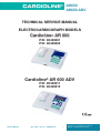
AR600 AR600 ADV TECHNICAL SERVICE MANUAL ELECTROCARDIOGRAPH MODELS Cardioline® AR 600 P/N: 80409501 P/N: 80409502 Cardioline® AR 600 ADV P/N: 80409511 P/N: 80409512 CARDIOLINE® is an et medical devices SpA brand 1 www.cardioline.biz AR600 AR600 ADV Index Introduction and special notes Programming for the installer Serial number Aim of the manual Reference standards Special notes pag. 4 pag. 4 pag. 6 pag. 6 pag. 7 pag. 7 1. Technical characteristics pag. 8 2. Description of the equipment 2.1 Casing 2.2 Battery 2.3 Mother board 2.4 Keyboard 2.5 Mark sensor board 2.6 Printer mechanical assembly complete with thermal head 2.7 Paper transport mechanical assembly 2.8 Battery charger pag. 10 pag. 10 pag. 10 pag. 10 pag. 11 pag. 11 pag. 11 pag. 11 pag. 11 3. Inputs and outputs 3.1 Connection to the patient input socket pag. 13 pag. 13 4. Checking the safety characteristics 4.1 Necessary instruments 4.2 Testing the applied voltage 4.3 Testing the leakage currents pag. 14 pag. 14 pag. 14 pag. 15 5. Checking the main technical features of the electrocardiograph 5.1 Necessary instruments 5.2 Checking sensitivity 5.3 Testing the ECG leads 5.4 Checking the paper transport speed 5.5 Checking the frequency response 5.6 Checking the battery charging system 5.7 Self-test to check the printer pag. 17 pag. 17 pag. 17 pag. 17 pag. 18 pag. 18 pag. 19 pag. 19 6. Identifying faulty circuits and analysis of the principal malfunctions 6.1 Foreword 6.2 Aim pag. 20 6.3 The equipment does not switch on 6.4 Illustration of the supply voltages 6.5 Malfunctions during printing 6.6 Malfunctions caused by faulty paper transport 6.7 Malfunctions during page set-up and sensing the presence of paper 6.8 Acquisition of the Ecg signal faulty or absent 6.9 The equipment does not accept the keyboard commands correctly 6.10 Led and/or display fault pag. 20 pag. 20 7. How to disassembly and reassembly the equipment 7.1 Introduction 7.2 Opening and closing the equipment 7.3 Removing the motherboard 7.4 Removing the battery 7.5 Removing the keyboard board 7.6 Removing the paper transport motor assembly 7.7 Removing the printer assembly 7.8 Removing the mark sensor board 7.9 Removing the paper compartment door 7.10 Removing and replacing the keyboard plate 7.11 Charging the batteries pag. 34 pag. 34 pag. 34 pag. 34 pag. 35 pag. 35 pag. 35 pag. 35 pag. 36 pag. 36 pag. 36 pag. 37 pag. 21 pag. 23 pag. 25 pag. 27 pag. 29 pag. 31 pag. 32 pag. 33 CARDIOLINE® is an et medical devices SpA brand 2 www.cardioline.biz AR600 AR600 ADV 8. Calibrations 8.1 General information 8.2 ECG AR 600 8.3 ECG AR 600 ADV pag. 38 pag. 38 pag. 38 pag. 39 9. General maintenance instructions 9.1 Introduction 9.2 Principal messages 9.3 Inspection frequency 9.4 Cleaning the thermal head pag. 41 pag. 41 pag. 41 pag. 41 pag. 42 10. List of spare parts 10.1 General information pag. 44 pag. 44 APPENDIX A Procedures for handling and storing electronic components sensitive to electrostatic discharge (ESD) pag. 46 Illustrated tables and figures pag. 48 CARDIOLINE® is an et medical devices SpA brand 3 www.cardioline.biz AR600 AR600 ADV INTRODUCTION AND SPECIAL NOTES This equipment, produced in two models without and with display, is a portable electrocardiograph with up to 3 print channels, with internal battery pack rechargeable with a specific class two battery charger. The patient input is CF type protected against defibrillation discharges. This equipment is used with the patient cables not protected against defibrillation supplied by the manufacturer. The recording may be made using heat-sensitive grid paper in a Z-fold pack or roll. The equipment has an IR infrared serial interface with the following functions: Model AR 600 (without display) for: • Loading the single-language software ( contact et medical devices for available languages). • Enabling the setup options such as: implementation of the number of print channels; program for main electrocardiographic parameters measurement ; PC archive function; PC ECG function. Model AR 600 ADV for: • Loading the single-language software ( contact et medical devices for available languages). • Enabling the setup options such as: program for main electrocardiographic parameters measurement ; program for diagnostic interpretation of the electrocardiogram; PC archive function; PC ECG function; program for monitoring arrhythmia and/or ST. PROGRAMMING FOR THE INSTALLER The equipment is supplied with the firmware in the language requested and the requested options enabled. Subsequent enabling of the setup options is carried out according to the procedures contemplated and requested et medical devices. Programming of the equipment in user mode is carried out according to the indications given in the user manual in the section “configuration of the electrocardiograph”. Starting of the serial installation of the software is activated within 12 seconds of selecting the command in the “update firmware” service menu. Ecg AR 600 The service menu is enabled by setting service mode and then pressing the filter, amplitude and speed keys in sequence and activating printing, then select and confirm “update firmware”. CARDIOLINE® is an et medical devices SpA brand 4 www.cardioline.biz AR600 AR600 ADV Ecg AR 600 ADV The service menu is managed on the display. With the “select” key and the “arrows” key, activate and confirm the menus: ! # $ % &' " % # $% # !" %& 1. Language of the print messages; 2. Options supported. " ( )** & #' " #" " %+ & '+# & ## $# &%' % #$ / $ , + % #- %% # . % Any Customer who wants to update the firmware of his equipment must communicate the following information to et medical devices spa 1. Part Number; 2. Serial Number; 3. Language; 4. Options requested; Et 1. 2. 3. 4. Medical Devices will then prepare a package containing: A customized firmware binary file for that particular equipment according to the Customer's requests; A special Applications Software (Loader) to be installed on a PC for managing the updating procedure; Operating Instructions; If necessary, an interface device RS 232 – IR. The updating procedure performs data transfer through the IR interface between the equipment and a PC according to a proprietary protocol and, once activated, it is completely clear to the user. NOTE: Since the updating phase must never be interrupted for any reason, it is recommended to perform it always with the batteries fully charged or with the equipment connected to the mains. At the end of update procedure (indicated by a message on the screen), the equipment restart according to the new configuration. If the firmware update procedure is not properly ended (indicated by an error message on the screen), the malfunction is almost certainly due to communication problems. The correct relative positioning between the two IR devices must therefore be checked, bringing them as close together as possible; eliminate any possible sources of interference (fluorescent lights) and try programming again. Depending on the stage of the updating procedure at which the interruption occurred, the following cases may be considered: - the Flash memory containing the firmware has not yet been modified: the equipment switches off and switches on again exactly as it was before the programming phase. - part of the Flash memory has been modified: the equipment switches off and switches on again, but, recognizing that it no longer has a valid code, it automatically prepares for the programming procedure, attempting to connect via IR with the PC. After a few attempts it switches off, but it is still possible to try programming again, switching it back on. In this case, after programming, the speeds and the mark must be calibrated. SERIAL NUMBER " # "+ ' $ & # % $## % % %' %& # ,# " 0. ( The label is divided into three parts: 1 - The top part shows the data concerning the dealer. 2 - The center part shows: The model (MOD) ________ the year of manufacture ________ The code number (REF) ________ the attention triangle ________ The serial number (SN) ________ CE 470 marking ________ 3 - The bottom part shows: the identification data of the Manufacturer ________ The code number of the model attributed by the Manufacturer ________ NOTE: Always use the serial number and the code of the equipment in any communications with the Dealer or with the Assistance Service. CARDIOLINE® is an et medical devices SpA brand 5 www.cardioline.biz AR600 AR600 ADV CE 0470 marking The mark of conformity CE 0470 shown on the name label of the device, applied on the bottom of the casing, certifies the conformity of the device with the essential requirements prescribed in enclosure I of the Directive 93/42/EEC, assimilated in Italy with the Decree Law No. 46 of 24 February 1997. The number 0470, shown alongside the CE mark, corresponds to the number of the Notified Body responsible for the application of the procedures contemplated in enclosure V of the Directive 93/42/ EEC. (In the specific case the Notified Body is NEMKO) AIM OF THE MANUAL The aim of this manual is as follows: a) to give a functional description of the unit; b) to give a description of the procedures necessary to perform a complete test of the equipment; c) to give a description of the procedures necessary to perform the safety tests according to the IEC safety standards; d) to identify and isolate faulty functional blocks; e) to describe the maintenance jobs necessary for correct and lasting operation of the equipment; f) to supply the list of spare parts. CARDIOLINE® is an et medical devices SpA brand 6 www.cardioline.biz AR600 AR600 ADV REFERENCE STANDARDS The safety characteristics of the medical electrical class equipment comply with the standards: # $ %% 1 #" # $#$ & % #& %&' $ #" ' # &' $ %% # &' $ %%( # &' )$ %%( # $ %%) 1 #" # $#$ & % #& %& ' $ #" ' ( # ($ %%( # " # #& # $#$ & % " % #$% # *& ( & $ # " # #& # $#$ #$ #" & % '# %& " # "# $' " # "" %$ # $ # #" % #$% # ( SPECIAL NOTES a) Remember that correct and efficient maintenance of the equipment and its accessories, following the instructions in this manual, ensures a long and safe working life of the equipment and its accessories. b) Remember that this service manual is intended only for competent technical personnel. c) Remember that all the instrumentation described or indicated in this service manual is necessary for correctly performing tests and calibrations, and for checking the safety features of the equipment. d) Remember that, whenever the equipment is opened for inspection or for servicing, a complete check of the safety characteristics must be made, as described in chapter 4, before it is returned to the user. e) Remember that this equipment has been designed using CMOS technology. Most of the electrical components belong to the family of ELECTROSTATIC SENSITIVE DEVICES (ESD). It is therefore necessary to follow particular working procedures. The particular procedures required when dealing with electrostatic sensitive devices (E.S.D.) are listed in appendix A. The manufacturer declines all responsibility for any damage sustained by the equipment, caused by an inadequate or inexistent working procedure necessary when dealing with E.S.D. devices. NOTE: The transport of the equipment in a non original package or packed in an incorrect way, relieves the manufacturer of all responsibility for damage sustained by the equipment and accessories and renders the guarantee void . f) This technical assistance manual has been prepared by et medical devices SpA, via De Zinis n. 6 - Cavareno (TN) Italia, which reserves all rights to modify it without notice and all copyright rights. g) Read the whole contents of this manual before starting the assistance service. CARDIOLINE® is an et medical devices SpA brand 7 www.cardioline.biz AR600 AR600 ADV 1. TECHNICAL CHARACTERISTICS Mains power supply Maximum absorption Mains power supply protection Internal electrical source Battery protection Internal power supply protection Applied part Protection against defibrillation Input dynamics Input impedance Common mode rejection Frequency response Time constant Acquisition Leads Signal memory Sensitivity of recording: manual automatic Writing system Print channels Paper transport speed Heat-sensitive paper Filters Serial interface Keyboard AR 600 Device with power supply specified class II (second) REF type: 6308. 100 mA at 117 V~ ± 10% 50 mA at 230 V~ ± 10% Fuse: T 0.5 A Set of rechargeable NiMH batteries 8 x 1.2 Vdc 1500 mAh PolySwitch 1.5 A - 40 °C in ambient conditions Pico fuse SHF SLO-BLO T 2 A Littelfuse CF type Internal ± 300 mV @ 0 Hz. ± 5 mV in the bandwidth > 100 Mohm on each electrode > 90 dB 0.5 to 150 Hz (-3dB) with anti-drift filter 3.3 seconds 11 bits 1000 0500 samples/sec/channel in calculation and filters Resolution 5µ V/bit 12 STANDARD leads 12 CABRERA leads (AR 600 ADV) acquired 8 reconstructed 4 (III - aVR - aVL - aVF) 10 seconds for each lead in auto isochronous 5 – 10 – 20 mm/mV ± 5% depends on the number of channels being printed 2.5 – 5 – 10 – 20 mm/mV ± 5% Thermal printer, 8 dots/mm Usable print height 50 mm 1–2–3 25 - 50 mm/s ± 5% Dot Card® in rolls : height 60 mm, length 15 m, gridded Dot Card® pack of Z-Fold : length 20 m, page 70x60 mm, gridded Mains disturbances: Digital filter notch modified 50 – 60 Hz with 32Hz -3db response to linear phase – switch on/switch off filter Anti drift: Digital filter 0.5Hz high pass with linear phase, always enabled and cannot be switched off Infrared Membrane type with 9 function and number with 13 LED function indicators CARDIOLINE® is an et medical devices SpA brand 8 www.cardioline.biz AR600 AR600 ADV Keyboard AR 600 ADV Display AR 600 ADV Interpretation program (optional) Operating modes Autonomy Recharging time Degree of protection of the casing Ambient conditions: Operation Transport and storage Dimensions Weight Conformity to standards Membrane type with 11 function keys, 10 alphanumeric keys and 1 LED function indicator graphic LCD 120x32 dots, rear-lit Interpretation ECG HES (AR 600 ADV): Developed by the Medizinische Hochschule Hannover Calculate parameters: Developed at the Institute of Clinical Physiology (National Research Council), Pisa - Italy Manual: real time acquisition Automatic: isochronous Internal set of batteries: 3 hours in 1 channel mode 10 mm/mV 25 mm/sec. 10 Hz p.v. Internal set of batteries: 14 hours 100% IP20 Ambient temperature: from +10°C to +40°C Relative humidity: from 25% to 95% (without condensation) Atmospheric pressure: from 700 hPa to 1060 hPa Ambient temperature: from -10°C to +40°C Relative humidity: from 10% to 95% (without condensation) Atmospheric pressure: from 500 hPa to 1060 hPa 250 x 60 x 185 mm (length x height x depth) 1000 grams with batteries, without paper EN 60601-1: 1990 EN 60601-1/A1: 1992 EN 60601-1/A2: 1995 EN 60601-1/A13: 1995 General standards for safety of electromedical equipment EN 60601-1-2: 1993 Standards on electromagnetic compatibility of medical equipment. EN 60601-2-25: 1995 Particular safety standards for electrocardiographs *& ( & $ # " # #& # $# $ #$ # $ # #" & % '# %& # " " % #$% # ( " # #" % $ "# $ ' " CARDIOLINE® is an et medical devices SpA brand 9 www.cardioline.biz AR600 AR600 ADV 2. DESCRIPTION OF THE EQUIPMENT All the internal parts of the equipment must be considered an applied part. The equipment is composed of the following main elements: - casing complete with paper compartment door, battery compartment door, keyboard plate and screen printing; - set of 8 NiMH batteries, 9.6 Volt; - principal electronic board referred to below as the “mother board”; - keyboard board; - mark sensor board; - printer mechanical assembly complete with thermal head; - paper transport mechanical assembly; - battery charging assembly outside the equipment. 2.1 CASING The casing is made of polycarbonate Lexan 940 color RAL 7035. 2.2 BATTERY Set of NiMH batteries with the following characteristics: - the set of batteries is protected against short circuits by a 1.5 A poly switch with self reset; - voltage 9.6 Vdc; - capacity 1500 mAh; - type supplied by the manufacturer of the equipment. NOTE ON SAFETY The battery may be replaced only with the type supplied as a spare by the manufacturer. 2.3 MOTHER BOARD This is a multilayer printed circuit board (four layers) in “fine-line” technology for mounting SMD (Surface Mounting Devices) components. It houses most of the equipment's electronic circuits. It may be subdivided into the following sections according to the electric block diagram with file name: TOP_LEVEL (I series) and 60_COMPL_II SERIE. 2.3.1 Section on battery charging The section on battery charging is composed of two parts: • an external part with a mains adapter AC/AC, 230/14.5 Vac or 115/14.5 Vac, protected by a fuse for short circuits and by PTC against overheating; • a part inside the equipment fed with 14.5 Vac composed of the following circuits: rectifying, filtering and current limiting circuits. These circuits do not allow operation of the equipment with the batteries run down or absent. 2.3.2 Section on the power supply to internal circuits It is composed of the following power supplies: • +5 V generated by a linear voltage regulator which feeds the control logic; • ± 5 VI – VL for supplying power to the patient input analog circuits on the hybrid circuit; • + 3.3 V generated by a linear regulator for supplying power to the analog/digital converter built into the microprocessor; • + 3 V reference voltage for the A/D converter. • VTPH voltage obtained from the battery for feeding the thermal head. This voltage is limited in current to 2 A (± 0.2 A) and stabilized in voltage at + 7.5 V (± 0.5 V). CARDIOLINE® is an et medical devices SpA brand 10 www.cardioline.biz AR600 AR600 ADV 2.4 KEYBOARD AR 600 2% # 3 # $04 #$ & % %'' #% + ' % % % $$ # $ #"" ( AR 600 ADV Contains 21 keys, 1 LED, 1 rear-lit liquid crystal display, graphic type, and the circuits for communication with the microprocessor by dedicated serial line. 2.5 MARK SENSOR BOARD 2% # %+ $ %& " # '# & % # %'# # ( 2.6 PRINTER MECHANICAL ASSEMBLY COMPLETE WITH THERMAL HEAD 2%' % $%& # # % The complete assembly is supplied as a spare part. % '#" #$# $%& % %& #$( ' # #" "' # & % % 2.7 PAPER TRANSPORT MECHANICAL ASSEMBLY Composed of the transport motor complete with support and gears. The complete assembly is supplied as a spare part. 2.8 BATTERY CHARGER The accessory defined as a battery charger is an AC/AC mains adapter, class II (second class), 230V~/14.4V~ or 115V~/14.5V~ which guarantees the insulation of the electrocardiograph with respect to the mains and feeds its battery charging circuit. IMPORTANT SAFETY WARNINGS The battery charger is a specific accessory that complements the electrocardiograph with the particular function of ensuring the electrical insulation of the patient and the operator with respect to the mains, when connected. For this reason, as well as guaranteeing the operation of the equipment, it has an essential safety function. Other similar accessories MUST NOT be used; the manufacturer declines all responsibility for damage due to tampering. The battery charger is a class II power supply and does not require ground connection of the electrical system PRECAUTIONS FOR USE • The battery charger can be damaged if dropped, struck or tampered with. • Do not immerse in water or other liquids; • When using it, do not place it on or near sources of heat. • Do not damage the cables for connection to the mains and to the electrocardiograph • Do not use or connect the electrocardiograph differently from the specifications. • Use the battery charger only at the specified mains voltage. CARDIOLINE® is an et medical devices SpA brand 11 www.cardioline.biz AR600 AR600 ADV 3. INPUTS AND OUTPUTS AR 600 – AR 600 ADV do not allow direct connections by cable to external equipments, but only with the use of IR infrared serial connection. 3.1 CONNECTION TO THE PATIENT INPUT SOCKET (table T1) 7 8 15 14 4 5 6 13 12 3 11 1 2 10 9 Socket seen from the connection side Pin 1 Pin 2 Pin 3 Pin 4 Pin 5 Pin 6 Pin 7 Pin 8 Pin 9 Pin 10 Pin 11 Pin 12 Pin 13 Pin 14 Pin 15 = IN C2 (electrode C2) = IN C3 (electrode C3) = IN C4 (electrode C4) = IN C5 (electrode C5) = IN C6 (electrode C6) = AGND (analog ground) = PAT5_10 (patient cable recognition line 5 – 10 electrodes) = DGND (digital ground) = IN R (electrode R) = IN L (electrode L) = IN F (electrode F) = IN C1 (electrode C1) = NC (not connected) = IN N (electrode N) = NC (not connected) The inputs have the following characteristics: a) Sensitivity 1 mV/ 5 - 10 - 20 mm. depending on the sensitivity selected and 1 mV/2.5 mm with automatic sensitivity; b) Input impedance greater than 100 MOhm each electrode; c) Input dynamics +/- 300 mV at 0 Hz. +/- 5 mV in the bandwidth; d) The inputs are protected against defibrillation CARDIOLINE® is an et medical devices SpA brand 12 www.cardioline.biz AR600 AR600 ADV 4. CHECKING THE SAFETY CHARACTERISTICS The safety standard requires two important tests: a) The applied voltage test: checks the efficiency of the insulation of the feeding circuits and of the circuits for connections with the patient. b) Testing of the leakage currents: measures the value of the leakage currents with relation to patient and operator safety. c) The equipment examined is composed of an external battery charger which can remain connected to the electrocardiograph connected to the patient. The insulation of the battery charger, between the mains supply and the socket for connection to the electrocardiograph, is ensured in class II (second class). The electrocardiograph is type CF. NOTE: All the safety tests must be carried out according to standards EN 60601-1 (1990 paragraphs 19 - 20) EN 60601-2-25 (1995). 4.1 NECESSARY INSTRUMENTS a) Instrument for testing dielectric rigidity: Manufacturer R/B model "UH28 M" Elektrotechn. Laboratorium D - 7015 Korntal Germany or equivalent; b) Instrument for measuring leakage currents: model “AMPLAID ST 10“ - Division Amplifon S.p.A. Italy, or model METRON QA 80” Electrical Safety Analyser, or model “BIO-TEK 601-PRO” Division Amplisim srl - Italy or equivalents. 4.2 TESTING THE APPLIED VOLTAGE The test must be performed in a suitable room complying with safety standards using the instrument 4.1 a). 4.2.1 Testing the equipment connected to the battery charger a) Apply the test voltage between all the pins of the patient connector and the pins of the mains plug of the battery charger connected to the electrocardiograph, see table T3. b) Test procedure: (class II electrocardiograph (second class). Apply a test voltage of 2 KVac for 10 seconds, then raise it to 4 KVac and keep it at this value for 1 minute. Then decrease it gradually within 10 seconds. c) Apply the test voltage between all the pins of the patient connector and a metal sheet with maximum dimensions 20x10 cm, pressed against the casing of the equipment, which is shifted in such a way as to control all the parts of the outer surface of the casing. Test procedure : (type CF electrocardiograph). Apply a test voltage of 0.750 KVac for 10 seconds, then raise it to 1.5 KVac and keep it at this value for 1 minute. Then decrease it gradually within 10 seconds. CARDIOLINE® is an et medical devices SpA brand 13 www.cardioline.biz AR600 AR600 ADV 4.2.2 WARNINGS Check that no superficial or destructive discharges are noted during the test. Slight discharges due to a corona effect may be overlooked, as long as they stop when the voltage is temporarily lowered to a lower value, which must however remain higher than the reference voltage U (250V), on condition that the discharges do not cause drops in the test voltage. Battery charger The battery charger is impregnated on the inside with polyurethane resin, so it is not repairable. So the test of dielectric rigidity between the applied part of the ECG and the mains must not be repeated, unless in the case of particular requirements. Electrocardiograph Performing the test between the applied part and the metal sheet in contact with the equipment is advised in the case of repairs. 4.3 TESTING THE LEAKAGE CURRENTS THIS TEST MUST BE PERFORMED AFTER EACH OPENING FOR INSPECTION AND/OR REPAIR USING THE INSTRUMENT 4.1 b AND IN ANY CASE EVERY TWO YEARS. Proceed as follows: 4.3.1 Connect the electrocardiograph connected to the battery charger to the measuring instrument following the instructions in the user manual of the instrument, remembering that: a) The leakage current towards the casing is measured between the mains power supply circuits and a metal sheet with dimensions no larger than 20 x 10 cm. which must be pressed against the casing of the equipment and of the battery charger together, see Fig. 18. b) The leakage current to the patient is measured between the mains and the applied part, see Fig. 20. For the connection with the applied part, use the same patient cable. c) The leakage current to the patient with mains voltage directly on the applied part (first fault condition) is measured between the metal sheet connected to the equipment and to the battery charger together and the applied part, see Fig. 21. d) The auxiliary current to the patient is measured individually on each electrode (except the black one) with respect to all the other electrodes connected together, see Fig. 26. 4.3.2 Set the measuring instrument according to the type (CF) and the class II (second) of the electrocardiograph. 4.3.3 Take the measurement following the indications in the user manual of the instrument and check that the values of the leakage currents measured are less than or equal to those given in table IV. CARDIOLINE® is an et medical devices SpA brand 14 www.cardioline.biz AR600 AR600 ADV Table IV Permanent admissible values of the leakage currents and of the auxiliary currents to the patient in mA (milliamperes). Current pathway Leakage current to casing Leakage current to patient Leakage current to patient with (mains voltage in the applied part) Auxiliary current to patient (+) N.C. = Normal condition (++) S.F.C. = First fault condition CF type N.C.(+) 0.1 0.01 ----0.01 S.F.C.(++) 0.5 0.05 0.05 0.05 NOTE: For the measuring system and the figures mentioned, refer to the standards: EN 60601-1: (1990) and EN 60601-2-25: (1995) paragraph 19. CARDIOLINE® is an et medical devices SpA brand 15 www.cardioline.biz AR600 AR600 ADV 5. CHECKING THE MAIN TECHNICAL FEATURES OF THE ELECTROCARDIOGRAPH 5.1 NECESSARY INSTRUMENTS: a) sample mV generator with the following characteristics: - pulse amplitude: 1mV +/- 3%; - pulse repetition frequency: 1 Hz; - frequency tolerance: +/- 1%; - max rising time: 1 ms. b) low frequency sinusoidal functions generator; c) ECG simulator. 5.2 SENSITIVITY TEST Proceed as follows: a) prepare the equipment for recording of 1 channel on the lead V1 with sensitivity 20 mm/mV.; b) connect the patient cable to the equipment; c) connect to the positive pole of the instrument 5.1 a) the terminal C1 of the patient cable connected to the equipment; d) connect all the other terminals of the cable to the negative pole of the instrument 5.1 a); e) make a recording for a few seconds; f) check that the recorded signal has an amplitude of 20mm. +/- 5% on all the channels (Reference: Standards EN 60601-3-2/Ed. 1); 5.3 TESTING THE ECG LEADS Proceed as follows: a) switch on the equipment; b) connect the patient cable to the equipment; c) connect the red terminal of the patient cable to the positive pole of the instrument in point 5.1.a and the remaining terminals to the negative pole. Start the recording and check that the amplitude in mm of the signal and its polarity (positive or negative) comply with the values listed in table 5.3. d) repeat the measurement in sequence with the remaining active terminals G - V - C1 - C2 - C3 - C4 - C5 - C6 of the patient cable with the same procedures as in point c) and check the correspondence with the values listed in table 5.3. CARDIOLINE® is an et medical devices SpA brand 16 www.cardioline.biz AR600 AR600 ADV + +,#- . '* '#* /'+, #+0'1. 02## 0+,2# 2 +3 + + 25 2% % 4 # +#0<= ± 0> # #" 2 6 ' #" 0 ' #"% % ① ②③④⑤⑥⑦⑧⑨ ⑩ 8 ' #" % #- + 9+ 3 ' #" % #- + 0* + #"&%' / " - 26 7 "$ #" #" % #$% # / #' "& # % 0':; 0*'' ± 4> 0': " # #" %$ $ '' ± 9> +'1. 2 5'.6 ' #" % % - 1 : 20 2@ 24 28 29 2) : ? '' 0* ? '' 0* ? '' * #: '' A 0* #: '' 9 : ' 9 :0 '' 4! 4 :@ '' 4! 4 :4 '' 4! 4 :8 '' 4! 4 :9 '' 4! 4 :) '' 4! 4 A 0* * 0* 9 A 0* 9 4! 4 4! 4 4! 4 4! 4 4! 4 4! 4 * A 0* A 0* 9 9 A 0* 4! 4 4! 4 4! 4 4! 4 4! 4 4! 4 * * * * * * A 0* * * * * * * * * * * * * A 0* * * * * * * * * * * * * A 0* * * * * * * * * * * * * A 0* * * * * * * * * * * * * A 0* * * * * * * * * * * * * A 0* TABLE 5.3 5.4 CHECKING THE PAPER TRANSPORT SPEED Proceed as follows: a) switch on the equipment and connect the patient cable; b) connect to the positive pole of the instrument 5.1 a) the terminal C1 of the patient cable; c) connect all the other terminals to the negative pole of the instrument 5.1 a); d) using the instrument with a square wave of 1Hz and an amplitude of 1 mVpp; e) record the signal on the lead V1; f) measure the length of the wave period recorded on the paper. It must give: Period = 50 mm +/- 5% for speed 50 mm/s; Period = 25 mm +/- 5% for speed 25 mm/s; 5.5 CHECKING THE FREQUENCY RESPONSE Proceed as follows: a) switch on the equipment and connect the patient cable; b) connect to the positive pole of the instrument 5.1 b) the terminal C1 of the patient cable; c) connect all the other terminals to the negative pole of the instrument 5.1 b); d) set the generator for a 10Hz sinusoidal wave with an amplitude of about 1mVpp.; e) select the lead V1 and the sensitivity 10 mm/mV.; f) make a recording and regulate the generator amplitude so as to obtain a 10mm excursion of the recorded signal; h) vary the generator frequency from 0.5Hz to 100Hz with a constant amplitude; g) check that the frequency response agrees with table 5.5. CARDIOLINE® is an et medical devices SpA brand 17 www.cardioline.biz AR600 AR600 ADV Signal amplitude in mVpv 1 Sinusoidal input signal in Hz without filter From 0.67 to 40 Tolerance for the signal 10 Hz – 10 mm ±10% 1 From 40 to 100 + 10% - 30% 0.5 From 100 to 150 + 10% - 30% Table 5.5 NOTE: - The anti-drift filter is of the digital type, 0.5 Hz high pass with linear phase, it is always switched on and cannot be switched off. - The 50 or 60 Hz filter eliminates mains disturbances of a notch modified digital type, with linear phase, it has a frequency response of 32 Hz –3dB. 5.6 CHECKING THE NiMH BATTERY CHARGING SYSTEM 5.6.1 Checking current limitation. a) Remove the set of batteries from the equipment as described in chapter 7.4. b) In the place of the battery, connect an ammeter, respecting the polarities with full-scale value 1 A. Feed the equipment with the battery charger and check that the current measured is 150 mA ±15%. 5.6.2 Checking the low battery indications. a) Remove the set of batteries from the equipment as described in chapter 7.4. b) In the place of the set of batteries, connect a d.c. power supply able to supply 5 A d.c. with a variable voltage from 0 to 15 Volt d.c. , taking care to respect the polarities. Switch on the equipment with a power supply of 10 Vdc, then slowly lower the voltage to 8.6 Vdc ±2%; the yellow LED indicating low battery begins to flash. Lower the voltage to 8.0 Vdc ±2%, the yellow LED remains lit. In this state the battery is completely run down. 5.7 SELF-TEST TO CHECK THE PRINTER The self-test is activated from the user menu. The printout obtained shows the alphanumeric characters, a triangular wave form to check the efficiency of the print head and of the signals with steps of 1 impulse per second for checking the two paper transport speeds 25 – 50 mm/sec. CARDIOLINE® is an et medical devices SpA brand 18 www.cardioline.biz AR600 AR600 ADV 6. IDENTIFYING FAULTY CIRCUITS AND ANALYSIS OF THE PRINCIPAL MALFUNCTIONS 6.1 FOREWORD With the introduction of SMT technology (Surface Mounting Technology) and of “fine line” multilayer printed circuits, it is extremely difficult to find and repair the fault even with suitable equipment. It is therefore advised not to attempt to repair the individual boards, but to replace them. An unsuitable intervention often prevents any possibility of repair when sent back to the factory. 6.2 AIM The aim of this chapter is to provide the repairer with useful information for identifying the board and/or assembly that is not working. For this purpose the analysis of the possible malfunctions or faults is summed up in flow charts and then developed in detail according to the circuit logic given in the general block diagram of the equipment and of the mother board. CARDIOLINE® is an et medical devices SpA brand 19 www.cardioline.biz AR600 AR600 ADV 6.3 THE EQUIPMENT DOES NOT SWITCH ON, FLOW ANALYSIS AND TECHNICAL DESCRIPTION (see wiring diagram, file name POWER_SUPPLY) EQUIPMENT DOES NOT START Battery charger connected Battery mode Verify fuse TEA across battery GOOD FAIL Verify max current flow 1,5 A d.c. Verify battery conditions FAIL Verify blown fuse cause GOOD Replace battery Verify 13 V~ battery charger Verify power supply voltage (See par. 6.4) GOOD Eliminate faulty conditions FAIL Verify rectifier circuits and current limiter Replace fuse Replace battery charger Verify ON/OFF circuits FAIL Replace or fix mother board FAIL CARDIOLINE® is an et medical devices SpA brand 20 www.cardioline.biz AR600 AR600 ADV 6.3.1 The type T 4A fuse that protects the battery is missing or burnt out • Check that the absorption of the equipment is lower than 1.5 A d.c. If the absorption is higher, find the cause. • After eliminating the cause, replace the fuse with one of an equivalent type. 6.3.2 Faulty batteries • They have leaked acid • They have swollen • They do not charge Replace the set of batteries with one of an equivalent type, voltage and capacity. 6.3.3 Checking the set of batteries To check the efficiency of the batteries with plate data 9.6 V - 1.5 Ah , proceed as follows: • Remove the set of batteries from the casing as described in chapter 7.4. • Charge it with an external power supply, with a voltage of 12 to 15 Vdc with a current limitation of 150 mA. • After charging it for 14 hours, discharge it on a resistance with a current of 1.5 A. If the voltage remains higher than 9.5 Volt for about 15 minutes the battery can still be considered efficient, otherwise its charging capacity is very limited and replacing it is advised. 6.3.4 Check external charging of the batteries • Connect the battery charger to the mains and check that its output voltage is 15 Vac ± 10%. 6.3.5 Checking the internal rectifying circuit and current limitation of the equipment • Remove the set of batteries. • Connect the equipment to the mains by means of the battery charger. • Connect a d.c. ammeter in parallel to the battery connector of the mother board. • Check that the current measured is 150 mA ± 10 %. 6.3.6 Checking the ON/OFF circuit • Pressing the ON/OFF key connects the ON_OFF_SW line to the positive pole of the battery. If the voltage measured is not higher than 8 Vdc the fault is due to the keyboard board or its connection, otherwise the mother board is faulty. CARDIOLINE® is an et medical devices SpA brand 21 www.cardioline.biz AR600 AR600 ADV 6.4 ILLUSTRATION OF THE SUPPLY VOLTAGES, FLOW ANALYSIS AND TECHNICAL DESCRIPTION (see wiring diagram, file name POWER_SUPPLY) Verify Power Supply Voltage Verify 13 V~ battery charger +5V digital circuits Verify battery nominal values: 9.6 V 1.5 Ah +/- 5 VL ECG imput circuits + 7.5 V (VTPH) Printhead Voltage +/- 5 VI ECG amplifier circuits + 3.3 V AD converter +3V Reference voltage AD converter For different V value replace mother board replace la board mother CARDIOLINE® is an et medical devices SpA brand 22 www.cardioline.biz AR600 AR600 ADV • • • • • • • 6.4.1 Illustration of the functions related to the power supply voltages The part concerning the battery charger has already been illustrated in chapters 6.3.4 – 6.3.5. + 5 V is generated by the IC13 regulator for supplying power to the digital circuits; ±5 VL supplies power to the input circuits of the ECG signal; ±5 VI supplies power to the amplification circuits of the ECG signal; + 3.3 V is generated by the IC 27 regulator and supplies power to the digital analog converter inside the microprocessor; + 3 V is a reference voltage for the AD converter generated by DZ4; + 7.5 V VTPH is the power supply voltage of the printer thermal head. This voltage is present only during printing, its current is limited to about 2 A and its voltage is stabilized at 7.5 Vdc. These functions are controlled by the circuit composed of Q3 – Q7 – Q8 – Q11. CARDIOLINE® is an et medical devices SpA brand 23 www.cardioline.biz AR600 AR600 ADV ( '. 6#0+,2# *6 ,#- / ,#+#-7 .2! '#'.8 , '#* + 03#,0'.* (see wiring diagrams, file name POWER_SUPPLY and IO_INT) 0 ,/+,2# PRINT OUT NO PRINT ABNORMAL Verify connection flat Too dark at any speed Too light or irregular Verify 7.5 VTPH Clean Printhead (cap. 9.4) FAIL GOOD Mother board failure Verify connections Verify 7.5 VTPH Verify printer signals GOOD Replace mother board Verify 7.5 Vd.c. and printer signals GOOD FAIL GOOD Replace printer Mother board failure Verify battery GOOD Replace mother board Verify mech.. failure Verify proper paper usage CARDIOLINE® is an et medical devices SpA brand 24 www.cardioline.biz AR600 AR600 ADV 6.5.1 Print absent • Check the efficiency of the connection between the thermal head and the mother board (flat). • With printing activated, check the power supply to the thermal head VTPH 7.5 Vd.c. ±0.5 measured on the drain of Q11 or pin 1 – 2 – 3 – 26 – 27 – 28 of J42. • Check the presence of an electrocardiographic or instrumental signal. • If the previous points have been checked, activate the print function of the equipment and check the following on the connector J42: a) The presence of the 3 MHz clock on pin 6 see Fig. 1; b) The presence of logic signals on the DATA lines on pin 25 (data) and LATCH on pin 5 see Fig. 1. c) The presence of a strobe square wave signal on pins 8 – 9 – 10 – 21 – 22 – 23 with a frequency of 1 KHz, see Fig. 1. In the presence of these signals as in Fig. 1, if printing is missing change the thermal head assembly. If on the other hand these signals do not correspond with the test points in Fig. 1 the fault is in the mother board which must be replaced. 6.5.2 Abnormal printing Electrical check • If printing is too intense at all speeds, check whether VTPH on pin 1 of J42 is higher than 8 Vdc (maximum thermal head supply voltage), if Vset is higher, the regulation circuit is faulty (see Q3 – Q7 – Q8 – Q11). • If the duration of the strobe impulse on pin 8 of J42 is longer than about 800 µsec. see Fig. 1 the mother board is faulty and must be replaced. • If the equipment is working regularly and printing disappears, check whether the battery is working correctly. Mechanical check • If the pressure between the thermal print head and paper roller is insufficient, check that the printer is correctly fixed onto the casing. If the printer is tilted the writing is irregular. • Check that the movement of the paper transport roller is not eccentric; if it is, change the paper guide. CARDIOLINE® is an et medical devices SpA brand 25 www.cardioline.biz AR600 AR600 ADV 6.6 MALFUNCTIONS CAUSED BY FAULTY PAPER TRANSPORT, FLOW ANALYSIS AND TECHNICAL DESCRIPTION (see wiring diagram, file name M_SPEED) WRONG PAPER SLIDES Paper does not slide Paper slides irregularly Verify paper door Verify paper roller and paper slides GOOD GOOD Verify motor and gear Verify presence of paper handler GOOD GOOD Verify motor connector Verify motor and gear GOOD GOOD Verify motor circuit and related power supply Verify motor circuit and related power supply GOOD GOOD Replace mother board Replace mother board CARDIOLINE® is an et medical devices SpA brand 26 www.cardioline.biz AR600 AR600 ADV 6.6.1 The paper does not move The principal causes are: • Paper guide badly closed, insert it correctly. • The teeth on the gears of the paper guide are spoilt (crushed), change the paper guide or the motor assembly. • Check the motor - mother board connection. • Check the motor power supply and control system, proceeding as follows: - check the presence of voltage from 9 to 14 V on the sender of Q10; check that on the line PWM0, after pressing the RUN key, there is a square wave generated by the microswitch to enable printing. • The presence of paper is ensured by checking the motor load. When out of paper (or when there is no paper) the transport roller of the paper guide exerts strong friction on the thermal head, causing motor overload. In this state the line ANA_IM (motor current analog input ) sends a signal to the microprocessor which puts the equipment into stop condition. In the opposite case of insufficient load when printing is activated (RUN) without the paper guide, the motor current control circuit produces the same effect on the microprocessor, which blocks printing. 6.6.2 The paper moves irregularly Faulty paper transport also causes malfunctions during printing and in mark control. • Perform all the mechanical checks illustrated in the previous chapter 6.6.1. • If the motor does not control the speed and goes too fast, the transistor Q10 is short circuiting or its command circuits are faulty. • If the paper speed is irregular, perform automatic calibration as illustrated in chapter 8. If the fault continues, change the mother board. CARDIOLINE® is an et medical devices SpA brand 27 www.cardioline.biz AR600 AR600 ADV 6.7 MALFUNCTIONS DURING PAGE SET-UP AND SENSING THE PRESENCE OF PAPER, FLOW ANALYSIS AND TECHNICAL DESCRIPTION (see wiring diagram, file name M_SPEED) PAGING and PAPER LOADED Wrong paging and in AUTO mode paper runs without printing Paper end not recognized, motor running in out of paper status Verify paper sensor and connections Verify motor overload control circuit GOOD FAIL FAIL Replace sensor Verify paper slide Mother board failure GOOD Verify calibration of paper marker sensor Replace mother board FAIL Replace mother board CARDIOLINE® is an et medical devices SpA brand 28 www.cardioline.biz AR600 AR600 ADV 6.7.1 The lack of control when out of paper may depend on: • Motor absorption control circuit, see chapter 6.6.1. • If the above conditions have not been found the mother board is faulty. 6.7.2 The lack of control of the black mark on the paper and respective malfunctions in automatic mode may depend on: • Dirty sensor FC1, clean the glass on top with a cloth. • Faulty connection between sensors board and mother board. Check the flatcable. • The calibration sensor voltage is not correct as described in chapter 8. • Faulty sensor Change the sensors board as described in chapter 7. • If the above conditions have not been found the mother board is faulty. CARDIOLINE® is an et medical devices SpA brand 29 www.cardioline.biz AR600 AR600 ADV 6.8 ACQUISITION OF THE E.C.G. SIGNAL FAULTY OR ABSENT (see wiring diagram, file name PAT_IN) VERIFY EKG ANOMALY Check patient cable and electrodes GOOD Check presence of 8 leads as output of hybrid circuit FAIL FAIL Replace broken items Replace mother board Bad acquisition of the ecg signal may depend on: • The patient cable is worn with interruption of the electrode/ECG connections. It is possible to ascertain this fault by making recordings in manual mode with the cable connected to an e.c.g. simulator • The fault in the electrodes may be checked by making a visual examination or by changing them. • Replace any part found to be faulty. • The failure to display the ecg leads on an oscilloscope connected to the outputs of the hybrid circuit IC5 indicates a fault in the analog part of the input. In this case change the mother board. CARDIOLINE® is an et medical devices SpA brand 30 www.cardioline.biz AR600 AR600 ADV 6.9 THE EQUIPMENT DOES NOT ACCEPT THE KEYBOARD COMMANDS CORRECTLY, FLOW ANALYSIS AND TECHNICAL DESCRIPTION (see wiring diagram, file name TAST_9T; TAST_ADV) FAILURE PERFORMING KEYBOARD COMMANDS Verify connector and flat cable Verify + 5 Vd.c. Verify keyboard • • • • • GOOD FAIL Replace mother board Replace keyboard In the presence of faults, it is good practice to check the efficiency of all the connections (flat - cables - connectors); if faulty, change them with a similar type supplied in the spare parts kit. Check the presence of voltage + 5 V. Check the cyclic presence of the clock at 3 MHz on pin 5 of J1. Check the operation of the keys and the LED with a tester. If the above-mentioned circuits are repairable and operating and the equipment does not accept any command, changing the mother board is advised. NOTE: The keyboard is managed by the microprocessor by means of a synchronous serial type interface with clock. 74HC589 PARALLEL IN-SERIAL OUT detects the pressure of a key and sends the related datum to the CPU. The integrated circuit 75HC595 SERIAL IN-PARALLEL OUT manages the lighting of LED and displays. CARDIOLINE® is an et medical devices SpA brand 31 www.cardioline.biz AR600 AR600 ADV 6.10 DEFECTS OF SIGNALLING OR DISPLAY DEVICES, LEDS AND/OR DISPLAYS, FLOW ANALYSIS AND TECHNICAL DESCRIPTION (see wiring diagram, file name TAST_9T; TAST_ADV) Abnormal LED's and display view Verify connection GOOD VERIFY + 5V GOOD FAIL Replace mother board Verify power supply on mother board cap. 6.4. If failure arises replace mother board Operation indications missing or faulty. The microprocessor manages the operation indications which are displayed by LEDs and/or displays by means of a serial type interface, synchronous with a clock. The integrated circuits 75HC595 SERIAL IN – PARALLEL OUT manage the lighting of LEDS and displays. The principal causes of malfunctions are: • faulty connections; • faults of the keyboard board or of the mother board, in this case check: the cyclic presence of the clock at 3 MHz on pin 5 of J1; the presence of the power supply + 5V on keyboard connector J40 pin 1; if missing or faulty, change the mother board; if the 5V are measured, change the keyboard board. CARDIOLINE® is an et medical devices SpA brand 32 www.cardioline.biz AR600 AR600 ADV 7. HOW TO DISASSEMBLY AND REASSEMBLY THE EQUIPMENT 7.1 INTRODUCTION Before opening the unit, all the necessary precautions must be taken to avoid possible errors or incorrect working procedures. In particular: a) always follow the instructions given in appendix A of this manual, concerning the work procedures, the necessary work instruments and the precautions to be taken when working with E.S.D. components. b) before closing the equipment again, check that all the subsets and connections have been correctly fitted; c) remember to perform all the operations involving handling of the boards only if earthed with the special protected bracelet. NOTE The safety characteristics (see chapter 4) must be checked after each opening and/or repair of the equipment, before it is returned to the customer. 7.2 OPENING AND CLOSING THE EQUIPMENT (table T1) Proceed as follows: a) remove the battery as in paragraph 7.4; b) remove the four M 2.5 x 10 mm TCB retaining screws from the bottom of the casing (table T1 Ref. 1); c) lift and remove the bottom of the casing of the equipment; d) to close the equipment, proceed in inverse order. NOTE: There are no dangerous voltages inside the equipment. 7.3 REMOVING THE MOTHER BOARD (table T2) a) Proceed according to the instructions in chapter 7.2 (opening the equipment). b) Unscrew and remove the four PT 2.5 x 10 mm TCB screws (table T2 Ref. 16). c) Lift the board by the patient connector side and disconnect in sequence from the board: • the keyboard flat; • the thermal head flat; • the mark sensor board flat; • the motor power supply connector. d) The replacement of the mother board requires the calibration of the paper transport speed and the mark presence sensor. d) To reassembly the board, repeat the procedure in back order. CARDIOLINE® is an et medical devices SpA brand 33 www.cardioline.biz AR600 AR600 ADV 7.4 REMOVING THE BATTERY (table T1) Proceed as follows: a) lay the equipment on a soft work surface with the bottom of the casing facing upwards; b) remove the door of the battery compartment after having slackened its retaining screw (table T1 Ref. 2); c) disconnect and remove the set of batteries; d) To reassembly, proceed in inverse order. ATTENTION: Do NOT revert the polarity of the battery, see table T1 rif. 5 – 6. 7.5 REMOVING THE KEYBOARD (table T2) Proceed as follows: a) proceed as in chapter 7.3 points a) - b) - c) for opening the equipment and removing the mother board. AR600 b) Remove the four PT 2.2 x 6 mm TCB retaining screws of the keyboard board with their washers and remove it, lifting it, see table T2 Ref. 1. AR600 ADV c) Remove the six PT 2.2 x 6 mm TCB retaining screws of the keyboard board with their washers and remove it, lifting it, see table T2 Ref. 1. d) Proceed in inverse order to reassembly the board and close the equipment. CAUTION: Remember to insert the nylon washers between the screws and the board. 7.6 REMOVING THE PAPER TRANSPORT MOTOR ASSEMBLY (table T2) Proceed as follows: a) proceed as in chapter 7.3 points a) - b) - c) for opening the equipment and removing the mother board; b) remove the M 2.5 x 8 mm TCB retaining screw with spring washer located on the gear support and lift the motor assembly, see table T2 Ref. 4; d) Proceed in inverse order to reassembly the motor assembly and close the equipment. 7.7 REMOVING THE PRINTER ASSEMBLY (table T2) Proceed as follows: a) proceed as in chapter 7.3 points a) - b) - c) for opening the equipment and removing the mother board from the equipment; b) remove the 2 retaining screws of the printer assembly, see table T2 Ref. 5, remove it from its seat, taking care not to damage the dots of the thermal head with hard objects; c) proceed in inverse order to fit the printer assembly, paying particular attention to the positioning of the mechanical part with screws, washers, etc.; d) to obtain long life of the thermal head, using exclusively the heat-sensitive paper recommended by the manufacturer, DOT-CARD in rolls and packs with height 60 mm is advised. The order code is marked on the bottom edge of the paper; CARDIOLINE® is an et medical devices SpA brand 34 www.cardioline.biz AR600 AR600 ADV e) the thermal head is extremely sensitive to electrostatic potentials, it is recommended always to follow the work procedures described in appendix A; f) the replacement of the printer assembly does not require any calibration. 7.8 REMOVING THE MARK SENSOR BOARD (table T2) Proceed as follows: a) proceed as in chapter 7.3 points a) - b) - c) for opening the equipment and removing the mother board; b) to remove the sensor board, force it upwards using a suitable tool. It is glued into its compartment inside the upper casing, see table T2 Ref. 20; c) to replace the board it is necessary to clean the area in which it is fitted, position it correctly in its compartment, with the output of the flat towards the paper compartment and stick it down with instant glue; d) to close the equipment perform the operations in inverse order; e) the replacement of the sensor card requires its calibration, see chapter 8. 7.9 REMOVING THE PAPER COMPARTMENT DOOR (table T 1) The paper compartment door system is a mechanical device, inserted in the casing, accessible from the outside, driven by the motor of the equipment, which transports the heat-sensitive paper. It is located above the paper compartment and covers it completely. To remove this part, proceed as follows: a) Insert a tool in the special hollow in the left-hand wall of the equipment where the paper comes out and exert pressure upwards so as to release the paper compartment door. b) This assembly must be disassemblyd before inserting a roll or pack of paper, when cleaning the roller and always before opening the equipment. c) To reassembly it, slip it into place with the rubber roller towards the inside of the equipment and holding it up on the other side. As soon as it is inserted, press gently down, on the raised side, so as to snap it shut. NOTE: If the roller is not clean and the paper compartment door is badly inserted or fastened, the paper transport is faulty and the equipment functions incorrectly. 7.10 REMOVING AND REPLACING THE KEYBOARD PLATE (table T1) The keyboard plate is an elastic membrane fitted on top of the keyboard board to allow its control buttons to be pressed . This self-adhesive plate is stuck onto the top of the equipment. To replace it when worn, lift one corner using a fine blade and pull it off the casing. If any adhesive is left on the casing, you must remove it by rubbing with your fingertips. To fit a new plate, center it with the corners in the space provided and press gently over the whole surface. NOTE: A broken or cracked keyboard plate is a threat to the safety of the equipment. CARDIOLINE® is an et medical devices SpA brand 35 www.cardioline.biz AR600 AR600 ADV 7.11 BATTERY CHARGER The equipments may be connected to a battery charger, an external accessory cod. 6308xxxx, supplied in two versions, for wall or table, with mains voltage 230 V~ – 115 V~. This accessory is not repairable and must be replaced if faulty. NOTE: The manufacturer declines all responsibility for any damage caused as a result of tampering. CARDIOLINE® is an et medical devices SpA brand 36 www.cardioline.biz AR600 AR600 ADV 8. CALIBRATIONS 8.1 GENERAL INFORMATION This equipment has an automatic system for calibrating the two paper transport speeds and the mark detecting sensor. The equipment does not require any other calibration. The calibration system may be activated from the service menu as follows: 8.2 ECG AR 600 To enter the service menu, switch on the equipment, select spanner mode, press in sequence the FILTER – AMPLITUDES- SPEED keys and activate printing with RUN. 8.2.1 Calibrating the mark Press the COPY key, the equipment prints the instructions for calibrating the mark. Position the paper in such a way that the mark does not overlap the sensor (visible near the outlet of the equipment), then activate the calibrating process with the RUN key. The microprocessor proceeds in automatic mode to read the voltages at sensor output, voltage with white paper and a black mark, then it calibrates the digital trimmer which regulates the current of the photodiode at optimum values and stores them in the memory. In the presence of the mark the calibration voltage is lower than 1.5 V. In the absence of the mark the calibration voltage is higher than 3.5 V. These values are shown in the printout, as is the numerical position of the digital potentiometer from 0 to 31 positions (wiper). NOTE: The mark presence sensor FC1 is visible by extracting the paper door from the paper compartment; traces of dust or other dirt on the protective glass alter the sensitivity of the sensor. Before proceeding with calibration it is good practice to check the surface of the glass and, if necessary, clean it with cotton wool soaked in alcohol. The sensor may be influenced by a strong light directed on the equipment. 8.2.2 Calibrating the speed Press the speed key, the equipment prints the instructions for calibrating the speed which may be carried out in manual or automatic mode for the speed selected. Calibration in automatic mode This is enabled with the COPY key. The paper runs and the number of revs of the motor is regulated automatically so as to obtain calibration of the speed selected. The final printout shows the speed calibrated at 25 or 50 mm/sec., the percentage value of the duty cycle, for modulation of the impulse width, generated by the microprocessor, determined according to the number of revs of the motor, and the number of revs of the motor. If the speed at calibration differs from the theoretical value by more than 15%, you must proceed in manual mode. Calibration in manual mode (checking) This is enabled with the MODE key from the speed calibration menu. The printout gives the instructions to be followed. CARDIOLINE® is an et medical devices SpA brand 37 www.cardioline.biz AR600 AR600 ADV Press the RUN key, the tracing gives a signal of 1 impulse per second for checking, then increase the value of the duty cycle by means of the SPEED key or decrease it with the AMPLITUDES key until you obtain calibration of the set paper transport speed. 8.2.3 Admissible tolerance of the paper transport speed • Speed 25 mm/sec. ± 5%; • Speed 50 mm/sec. ± 5%. 8.3 ECG AR 600 ADV The access sequences to the various menus are guided on the display. To enter the service menu switch on the equipment, press the MENU key, select with the arrow key (DOWN) and confirm the submenus INSTRUMENTS, SELF-TEST, SERVICE, then press in sequence the FILTER – AMPLITUDES – SPEED – RUN keys and confirm. 8.3.1 Calibrating the mark Confirm the submenu “mark calibration”, position the mark far from the sensor, (visible near the outlet of the equipment), confirm “forward”. The microprocessor proceeds in automatic mode to read the voltages at sensor output, voltage with white paper and a black mark, then it calibrates the digital trimmer which regulates the current of the photodiode at optimum values and stores them in the memory. In the presence of the mark the calibration voltage is lower than 1.5 V. In the absence of the mark the calibration voltage is higher than 3.5 V. These values are shown in the printout, as is the numerical position of the digital potentiometer from 0 to 31 positions (wiper). 8.3.2 Calibrating the speed Confirm the submenu “cal.speed”, select the speed to be calibrated 25 or 50 mm/sec. and confirm. Calibration in automatic mode Confirm the menu, the equipment performs calibration in automatic mode and then shows on the display the percentage value of the duty cycle, for modulation of the impulse width, generated by the microprocessor, determined according to the number of revs of the motor, and the number of revs of the motor. If the speed at calibration differs from the theoretical value by more than 15%, you must proceed in manual mode. Calibration in manual mode (checking) Select and confirm the submenus “cal.speed” , the speed to be calibrated “25 mm/sec.” or “50 mm/sec.” and “manual” calibration mode. The display next shows the messages: Output PWM0 – Duty = xx.x% with the possibility of selecting test – change – quit. Confirming the “test” command enables paper transport and the printout shows a signal of 1 impulse per second, from which you calculate whether to increase or decrease the duty cycle to obtain the set paper transport speed. Next select and confirm “change” and act accordingly. When the speed has been correctly calibrated, select and confirm “quit”. NOTE: All the set data and the configuration of the equipment are saved each time it is switched off. CARDIOLINE® is an et medical devices SpA brand 38 www.cardioline.biz AR600 AR600 ADV 9. GENERAL MAINTENANCE INSTRUCTIONS 9.1 INTRODUCTION The electrocardiograph AR 600 and AR 600 ADV has been designed with the aim of ensuring high reliability and ease of maintenance of the product during its life cycle and use. However, it is always necessary to follow the instructions in the service manual and in the user manual scrupulously during the whole working life of the equipment. The electrocardiograph is equipped with a computerized automatic system which is able to control and manage all operation of the equipment. Any conditions of incorrect use or abnormal operation are indicated by the flashing of green LEDs or the lighting of amber LEDs, by messages on paper and on the display. The programming phase is guided by the respective printout in the ECG AR 600, while in the ECG AR 600 ADV it is guided on the display. 9.2 PRINCIPAL MESSAGES AR 600 #~ Led Green LED Amber LED O Amber LED Flashing green speed LEDs Flashing green LED Green LEDs lit Flashing green LED All the LEDs lit except the mains LED and low battery LED Messages on paper AR 600 ADV Messages on the display Indication of operating status Battery charging Low battery - Inputs saturation - Parameters calculation phase or analysis Out of paper and/or door open Acquisition phase ended Service menu enabled Setup menu enabled Firmware updating and Serial Number setting phase • Programming Guide • Functional information All the information on programming, use and functions. CARDIOLINE® is an et medical devices SpA brand 39 www.cardioline.biz AR600 AR600 ADV 9.3 INSPECTION FREQUENCY To guarantee a safe and long working life, the equipment and its accessories must be periodically inspected and checked. Tables 9.3.1 and 9.3.2 indicate the type of checking required and its frequency, referring to normal use of the electrocardiograph (about 4000 ECG recordings a year). Safety check +9 2 # % : ; "# # $( + # - @ 9 # #2+ $ %$ #& %' "# + 2% %& ( ' #& & %' $ & % " #% Table 9.3.1 Functional and visual check +9 : - checking and cleaning the printer head dots ; 9 every 3 months - checking and cleaning the paper transport roller every 3 months - checking the battery charger, cables and connectors every 3 months - checking the paper transport speed every year - checking the keys and the keyboard every year - checking the keyboard plate every year - cleaning the paper compartment and the mark presence sensor every year - checking the cables, patient cable and electrodes every year - checking the battery every year - calibration every year Table 9.3.2 CARDIOLINE® is an et medical devices SpA brand 40 www.cardioline.biz AR600 AR600 ADV 9.4 CLEANING THE THERMAL HEAD 9.4.1 Introduction As indicated in table 9.3.2 it is necessary to clean the thermal head periodically when the equipment is switched off. Correct periodic cleaning of the thermal print head ensures a faithful and precise reproduction of the E.C.G tracing and long life of the print system. 9.4.2 Necessary instruments a)THERMAL HEAD cleaning brush cod. 66020004. 9.4.3 Cleaning procedure Proceed as follows: a) remove the paper transport guide door; b) clean the dots of the thermal head with the special brush taking care not to touch the head with your hands or other objects. NOTE: the thermal print head is extremely sensitive to electrostatic potential. It is therefore recommended not to touch it for any reason! In case of necessity, handle it after being earthed by means of a suitable strap or protected bracelet. CARDIOLINE® is an et medical devices SpA brand 41 www.cardioline.biz AR600 AR600 ADV 10. LIST OF SPARE PARTS 10.1 GENERAL INFORMATION The part code numbers of the spare parts are listed in tables 10.1 and 10.2. The part code, if any, is indicated on the identification label, inside the equipment. To order a spare part, use the corresponding code. List of spare parts for AR 600 code 80400002 Part code Description 39701070 39701300 39701301 39701305 39701307 39701308 39701309 39701496 39701496E 39701497 39701511 39701512 39701513 39701575 FUSIBILE 4,00 A SLO-BLO SMD (10PZ) BATTERY PACK (4+4) X 1,2V CHIMOGRAFO X AR 600 PORTAROTOLO AR 600 SCHEDA SENSORE TACCA AR 600/AR 1200 SCHEDA TASTIERA AR 600/AR 1200 STAMPANTE COMPLETA AR 600 SCHEDA MADRE AR 600 CARDIOLINE SCHEDA MADRE AR 600 CARDIOLINE (EXCHANGE) TARGH. TASTIERA E MARCHIO AR 600 C/LINE SPORTELLO PILE X S/MICRO 1 RAL 9003 GUIDACARTA AR 600 RAL 9003 MOBILE INFERIORE COMP. AR 600 RAL 9003 MOBILE SUPERIORE COMP. AR 600 RAL 9003 Table 10.1 B " # ' '% %# $ " $ %' " + # %&+# " #$ ; ********( % #" " $- %& %$ ' #" ' " # , & % " # ' %& '% %# $! & %" " %+ $##' " $/ . , . # % % + #% +" " # $ #" " +" " % $ % ; #$ %$ #" & '+# , # &" %" %#$ % % % -% " # $( %#$ # " # % . ! CARDIOLINE® is an et medical devices SpA brand 42 www.cardioline.biz AR600 AR600 ADV List of spare parts for AR 600 ADV Part code code 80400003 Description 69701070 69701300 69701301 69701305 69701307 69701309 69701328 69701498 69701498E 69701499 69701511 69701512 69701513 69701576 FUSIBILE 4,00 A SLO-BLO SMD (10PZ) BATTERY PACK (4+4) X 1,2V CHIMOGRAFO X AR 600 PORTAROTOLO AR 600 SCHEDA SENSORE TACCA AR 600/AR 1200 STAMPANTE COMPLETA AR 600 SCHEDA TASTIERA AR 600 ADV/AR 1200 ADV SCHEDA MADRE AR 600 ADV CARDIOLINE SCHEDA MADRE AR 600 ADV CARDIOLINE (EXCHANGE) TARGH. TAST. E MARCHIO AR600ADV C/LINE SPORTELLO PILE X S/MICRO 1 RAL 9003 GUIDACARTA AR 600 RAL 9003 MOBILE INFERIORE COMP. AR 600 RAL 9003 MOBILE SUPERIORE COMP. AR600ADV RAL9003 Table 10.2 B " # ' '% %# $ " $ %' " + # %&+# " #$ ; ********( % #" " $- %& %$ ' #" ' " # , & % " # ' %& '% %# $! & %" " %+ $##' " $/ . , . # % % + #% +" " # $ #" " +" " % $ % ; #$ %$ #" & '+# , # &" %" %#$ % % % -% " # $( %#$ # " # % . ! CARDIOLINE® is an et medical devices SpA brand 43 www.cardioline.biz AR600 AR600 ADV APPENDIX A 1. PROCEDURES FOR HANDLING AND STORING ELECTRONIC COMPONENTS SENSITIVE TO ELECTROSTATIC DISCHARGE (ESD) 1.1 GENERAL INFORMATION All modern electronic components, in particular those based on CMOS technology, may be irreparably damaged by even very slight electrostatic discharges. Precautions must be taken against electrostatic discharges when handling and working with electronic components sensitive to electrostatic discharges: ELECTROSTATIC SENSITIVE DEVICES (ESD). 2. PROCEDURE 2.1 PROTECTION OF THE WORK AREA 2.1.1 PERSONAL PROTECTION SYSTEMS The personnel involved in control, storage, dispatch and assembly operations must be earthed by means of a special conductive bracelet complying with safety regulations. If this precaution cannot be used, the operator must wear suitable footwear, of an antistatic type. 2.1.2 PROTECTION OF WORKING EQUIPMENT AND INSTRUMENTS Working equipment must be earthed. Tables, worktops and other surfaces on which the components are handled must be covered with conductive material and earthed. All tables and worktops must be covered with a layer of conductive material and earthed. The repair technician must also be earthed with a protected special bracelet complying with safety regulations. 2.2 PACKING AND DESPATCH The material must be packed in special antistatic bags or containers and marked with labels complying with MIL STD 129J. The containers must guarantee adequate protection against impact and handling during transport. 2.3 STORAGE All E.S.D. components must be stored in their original boxes and placed in special metal containers. During storage in the warehouse, electronic components must be kept in their original packaging. Any containers must be made exclusively of metal and/or conductive material. In case of direct handling, the personnel must take the precautions described in point 2.1.1. CARDIOLINE® is an et medical devices SpA brand 44 www.cardioline.biz AR600 AR600 ADV 2.4 HANDLING BOARDS WITH ELECTRONIC COMPONENTS During handling operations, the board must be placed in special antistatic containers. 2.5 IDENTIFICATION OF ESD COMPONENTS Each component sensitive to electronic discharges is identified with the letters ESD. In the Warehouse area, the containers are marked with a special symbol. 2.6 RECOMMENDATIONS AND RESPONSIBILITY Follow all the instructions in this procedure when dealing with E.S.D. components. The manufacturer does not accept responsibility for any damage to the equipment caused by insufficient or unsuitable methods of treatment, handling or work. CARDIOLINE® is an et medical devices SpA brand 45 www.cardioline.biz AR600 AR600 ADV ILLUSTRATED TABLES AND FIGURES FIGURE 1 TEST POINT THERMAL HEAD PILOTING TABLE T1 EXTERNAL VIEWS OF THE EQUIPMENT TABLE T2 INTERNAL VIEWS OF THE EQUIPMENT TABLE T3 PARTICULAR VIEWS CARDIOLINE® is an et medical devices SpA brand 46 www.cardioline.biz AR600 AR600 ADV Service Manual Lang CODE REV OM 01 02 ----- Revision Sheet ECG AR 600 – AR 600 ADV English 80409501-80409502-80409511-80409512 DESCRIPTION DATE SIGLA AP/DC CARDIOLINE® is an et medical devices SpA brand 47 www.cardioline.biz