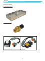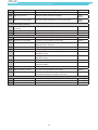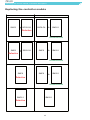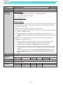
1
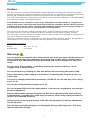
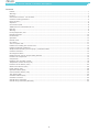
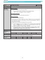
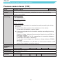
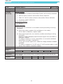
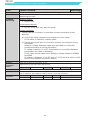
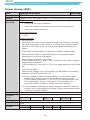
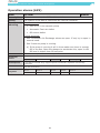
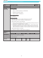
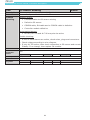
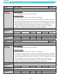
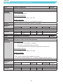
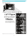
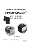
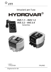
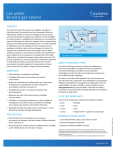
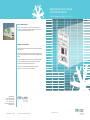
Operating and service manual
Controlled Atmosphere
Star Cool refrigeration unit Model SCI - XX - X - CA
24-hour hotline support
Call us at +45 7364 3500 or send us an e-mail at service@starcool.
dk. Our service department is available 24 hours a day, 7 days a week providing easy access to the answers you need.
Guideline: Order procedure
Purchase spare parts for the Star Cool reefer machine fast and reliable
via the internet.
Customers, service providers and other repair shops order directly from
Star Cool. Vessels shall contact the relevant customer (shipping line) for
ordering.
All orders are placed centrally with Star Cool where our staff will assign
the order to the distribution centre located closest to the required
delivery address and arrange shipment from there.
To be able to order spare parts from www.starcool.dk, please
register at the site, to receive a login and password.
Bjerndrupvej 47
6360 Tinglev, Denmark
Phone: +45 73 64 34 00
Fax.: +45 73 64 35 69
E-mail: [email protected]
www.starcool.dk
Version 810800A - Dec 2010
© Copyright 2010 Maersk Container Industry AS
Version 810800A - Dec 2010
Operating and service manual, Controlled Atmosphere
Preface
The Star Cool CA is a controlled atmosphere system designed to prolong the shelf life of perishables by regulating the internal atmosphere of the container. The container’s atmosphere obtains the
desired gas composition based on entered set points for O2 and CO2 via the controller.
The desired atmospherical composition of the gas serves to lower the respiration of the perishables,
and thereby providing a prolonged shelf life.
ATTENTION! Due to regulation of the cargo atmosphere during transport, oxygen level
may be low and/or carbon dioxide level high inside the container! Please check gas levels
and flush with fresh air before entering and unloading. Exposure to low oxygen/high carbon dioxide may cause loss of consciousness and suffocation.
This version of the manual is dated December 2010, edited by Maersk Container Industry AS.
All rights reserved. This user’s manual is valid for software version 0345 or newer versions.
The information herein is subject to change without notice and does not represent a commitment on
any part of Maersk Container Industry AS.
While the information herein is assumed to be accurate, Maersk Container Industry AS assumes no
responsibility for any errors or omissions that may appear in this documentation.
This manual is valid for:
Model
Release Date
SCI - XX - X - CA
01.12.2010
Warnings
Do not operate or maintain this refrigeration unit until you have familiarized yourself completely with the equipment and operating of this unit by reading the instruction in this addendum and the Operating and service manual for Star Cool
units.
Do not enter the container - including opening the service hatches - when
oxygen level is below 20.9%.
Do not perform any welding on the unit before disconnecting the power plug.
Disconnect main power supply to unit before inspecting the interior of the controller box.
The unit is charged with R134a and ester oil BSE 55. Do not use any other refrigerant or oil.
Do not use contaminated refrigerant or oil.
Do not release R134a into the atmosphere. Use recovery equipment according to
present legislation.
During maintenance please observe that R134a is operating with high and low
temperatures in combination with high pressures, which may cause personal injuries if not handled properly.
During recovery and maintenance of R134a unit personal protection equipment
has to be worn.
Do not trap any liquid refrigerant inside pipes during soldering work. This may
lead to explosion of pipe.
1
Operating and service manual, Controlled Atmosphere
Contents
Preface .......................................................................................................................................................1
Warnings ....................................................................................................................................................1
Legend........................................................................................................................................................3
CA function overview - two versions ...............................................................................................................3
Container venting procedure .........................................................................................................................5
Menu structure ............................................................................................................................................7
Setpoints ....................................................................................................................................................8
CA function on/off ........................................................................................................................................8
Additional menu information for CA ................................................................................................................8
Data log ......................................................................................................................................................9
Warning ......................................................................................................................................................9
Pre Trip Inspection, PTI.................................................................................................................................9
Manual inspection ...................................................................................................................................... 10
Function test ............................................................................................................................................. 10
Operation .................................................................................................................................................. 10
Manual mode ............................................................................................................................................. 10
CA curtain ................................................................................................................................................. 11
Vacuum system test ................................................................................................................................... 11
Problem surrounding the vacuum hose ......................................................................................................... 12
Problem located at membrane ..................................................................................................................... 12
Simple trouble shooting vacuum pump / controller module ............................................................................. 12
Container leak test ..................................................................................................................................... 12
Oil charge and drain ................................................................................................................................... 13
Replacement of vacuum pump heating element ............................................................................................. 13
Locations of components ............................................................................................................................. 14
Components .............................................................................................................................................. 15
Replacing the controller module ................................................................................................................... 18
Temperature sensor alarms (1XX) ................................................................................................................ 19
Pressure sensor alarms (2XX)...................................................................................................................... 22
Other sensor alarms (3XX) .......................................................................................................................... 26
Power alarms (4XX) ....................................................................................................................................28
Operation alarms (6XX) .............................................................................................................................. 29
Communication alarms (7XX) ...................................................................................................................... 36
Test alarms (8XX).......................................................................................................................................39
Controller alarms (9XX) .............................................................................................................................. 47
Controller overview .................................................................................................................................... 49
Overall wiring schematic ............................................................................................................................. 53
Overall wiring schematic (alternate) .............................................................................................................54
2
Operating and service manual, Controlled Atmosphere
Legend
Short name
Name
Pmem
Membrane pressure
Tpump
Vacuum pump temperature
Mpump
Vacuum pump
Hpump
Heating element
Mair
Fresh air motor
CA function overview - two versions
Inside Container
O2
CO2
CA membrane
Fresh air valve
RS 485
Pressure sensor
P
Output
Vacuum Pump
Controller
module SMC6
PTC
RS 485
Thermal circuit
switch
(Only available for some models)
RS 485
Signals
Vacuum
Air flow
PTC
Temperature sensor
Vacuum pump
Heating element
3
Controller
module SSC6CA
Operating and service manual, Controlled Atmosphere
Inside Container
O2
CO2
CA membrane
Fresh air valve
RS 485
Pressure sensor
P
Output
Vacuum Pump
PTC
RS 485
Controller
module SMC6.1
Signals
Vacuum
Air flow
PTC
Temperature sensor
Vacuum pump
Heating element
4
Operating and service manual, Controlled Atmosphere
The basic principle is that the fruit will generate CO2 from O2 via respiration. This will increase the
CO2 level and decrease O2 level inside the container. When the CO2 level reaches above the CO2
set point the vacuum pump will activate and evacuate CO2 with the selective membrane. In case
the O2 level goes below the O2 set point the fresh air valve will open and let in ambient air (20,9%
O2). This described mechanism will regulate the gas concentration within the container as illustrated
below:
Gas
Concentration
O2 level
CO2 level
Time
Warning
Due to low oxygen levels inside the container, ventilation is necessary before entering, either
for repairing the unit or unloading. Stay away from doors while venting.
Container venting procedure
TO BE PERFORMED WHENEVER ENTERING THE UNIT/CONTAINER IS NECESSARY
1.
2.
3.
4.
Press
for operation and select O03 and set Air flow mode to “NORMAL”.
Open fresh air module fully. AL 834 may appear.
Wait for O2 level to reach 21% +/- 2% before entering.
Close air module and clear AL 834.
General specification
Additional components to a standard unit:
•
•
•
•
•
•
O2 sensor
CO2 sensor
Vacuum pump
Membrane
Vacuum hose
Fresh air module incl. motor
Fresh air motor
Type
Gear motor
Supply
12-24 V DC
CO2 sensor
Type
Nondispersive infrared sensor
Operating range
0 - 20%
5
Operating and service manual, Controlled Atmosphere
Accuracy
CO2 (5%) +/- 0,3%
CO2 (0,5%) +/-0,1%
Supply
8-15V DC
Output
RS-485
O2 sensor
Type
Ziconium Oxide
Operating range
0 - 21%
Accuracy
At O2 (3%) +/- 0,5%, temperature ranges
from -1 - 15°C
Supply
8-15V DC
Output
RS-485
Pressure transmitter
Type
Ratiometric
Operating range
-1 - 0 Bar
Accuracy
±10 mBar
Supply
5V DC
Output
Ratiometric
Temperature sensor
Type
NTC, 10 kOhm at 25°C (77°F) 10K3A1
Operating temp.
-40°C to 100°C (-40°F to 212°F)
Accuracy
±0.15°C, range -30°C to 100°C (±0.5°F,
-22°F to 212°F)
Vacuum pump, including heating element
Capacity
16 m3/h at 50 Hz and 19 m3/h at 60 Hz
Supply
3 phase AC 50 Hz 340 – 460 Volts and 60 Hz
400-520 Volt
Oil (type/amount)
Anderol FGC 32 - 0.35 L
6
Operating and service manual, Controlled Atmosphere
Menu structure
MAIN PAGE
AIR EXCHANGE
888m3/h
Press (X) to leave
I01
I02
I03
I04
I05
I06
I07
I08
I09
I10
I11
I12
I13
I14
I15
I16
I17
I18
I19
I20
I21
I22
I23
I24
I25
I26
I27
I28
I29
I30
I31
I32
I33
I34
I35
I36
O01
O02
O03
O04
O05
O06
O07
O08
O09
A01
A02
...
A16
S01
S02
S03
S04
S05
INFORMATION
Relative humidity
Air exchange
O2
CO2
Last defr interval
USDA 1 temp
USDA 2 temp
USDA 3 temp
Cargo temp
Time to defrost
Ambient temp
Supply air 1 temp
Supply air 2 temp
Return air temp
Evaporator temp
Suction temp
Suction press
Membrane pressure
Discharge press
Expansion valve
Evap superheat
Compressor freq
Power frequency
Current phase 1
Current phase 2
Current phase 3
Voltage phase 1-2
Voltage phase 2-3
Voltage phase 1-3
Phase direction
Battery voltage
FC temp
Condenser fan
Evaporator fan
Evaporator heater
Pump temperature
P01
P02
P03
OPERATION
M01
M02
M03
M04
M05
M06
M07
M08
M09
M10
B01
B02
B03
B04
B05
D01
D02
D03
D04
D05
D06
ALARM
L01
L02
L03
L04
Alarm text
...
MANUAL OPERATION
DATALOG VIEW
TIME ADJUST
RUNTIME COUNTERS
CONFIGURATION
C01
C02
C03
C04
C05
>
>
>
>
>
PRE TRIP INSPECTION
T01
T02
T03
T04
T05
T06
T07
T08
T09
T10
T11
T12
T13
T14
T15
T16
T17
T18
T19
T20
T21
Active program
Multi. Temp setp.
Cold treatment
>
>
COLD TREATMENT
Duration
Maximum USDA temp.
Treatment setpoint
Final temperature
CT status
MULTI. TEMP. SETP.
Setpoint
QUEST
Airflow mode
Humidity setpoint
Datalog interval
PROGRAMS
>
O2 setpoint
CO2 setpoint
Active application
SERVICE
PROGRAMS
PTI test
Last
Function test
Abort the test
Test status
10: Init
20: Controller
30: Power
40: Evap fan
50: Cond fan
60: Evap heater
70: CA
80: Compressor
90: FT status
105: T set 13 °C
100: T set 5 °C
110: T set 0 °C
111: Hold 0 °C
120: T set -18 °C
130: Defrost
140: PTI status
R01
R02
R03
R04
R05
R06
R07
F01
F02
F03
F04
F05
F06
F07
F08
F09
F10
7
Hour
OFF
OFF
OFF
OFF
OFF
OFF
Set
0.0
0.0
0.0
0.0
0.0
0.0
%Rh
OFF
OFF
OFF
OFF
OFF
OFF
MANUAL OPERATION
Operating mode
Evaporator heater
Evaporator fan
Condenser fan
Compressor freq
Expansion valve
Hotgas valve
Economizer valve
Airex motor
Vacuum pump
DATALOG VIEW
Text Temperatures
Text Atmosphere
Graph Temperatures
Graph Atmosphere
>
>
>
>
TIME ADJUST
GMT-Year
GMT-Month
GMT-Day
GMT-Hour
GMT-Minute
RUNTIME COUNTERS
Unit
Compressor
Evaporator fan
Condenser fan
Evaporator heater
Airex motor sw times
Vacuum pump
CONFIGURATION
Container
Software version
FC type
FC ID
Phase detection
AirEx calibration
Low pres type
High pres type
Main PCB
Model code
Operating and service manual, Controlled Atmosphere
Setpoints
Setpoints are entered via the operation menu
O2 range 3 - 21%
CO2 range 5 - 12%
Setting setpoint: O2 level is set in O07 and CO2 level is set in O08 (Menu structure)
CA function on/off
If the setpoints for O2 and CO2 is set to OFF the CA function is turned off
Additional menu information for CA
In addition to the standard log the following information can be viewed in the log:
Please note that it will take approx. 5 minutes before CO2 and O2 can be viewed in the
display.
I03 O2 level
Function:
Shows the O2 level [%]
Value:
An actual value of the O2 level inside the container.
I04 CO2 level
Function:
Shows the CO2 level [%]
Value:
An actual value of the CO2 level inside the container.
I18 Membrane pressure
Function:
Membrane pressure.
Value:
Actual vacuum pressure between vacuum pump and membrane. Under normal conditions: 40-100
mBar.
StarView enables the display of the following additional information.
O07 O2 set point
Function:
O2 set point.
Value:
-
O08 CO2 level
Function:
CO2 set point.
Value:
-
8
Operating and service manual, Controlled Atmosphere
Data log
Title
Info displayed
CO2Set
CO2 set point [%]
O2Set
O2 set point [%]
Input CO2
CO2 level [%]
Input O2
O2 level [%]
Input Pmem
Membrane pressure [mBar]
Input Tpump
Oil temperature in the vacuum pump [°C]
Application CAType
0 = CA off
1 = CA on
Control MpumpCA
0 = vacuum pump off
1 = vacuum pump on
Control HpumpCA
0 = heating element off
1 = heating element on
Control MairPct (time opened [%])
0 = fresh air valve closed
100 = fresh air valve open
Warning
Do NOT enter the container, including opening the service hatches, when the oxygen level is below
20.9% (equal ambient air).
Human response to oxygen low atmosphere:
Oxygen content of Air Symptoms of a person exposed
20.9%
Level in ambient air - no effect
15% - 19%
May impair coordination and may induce early symptoms
in persons who have coronary, pulmonary or circulatory
problems.
12% - 15%
Respiration and pulse increase; impaired coordination, perception
and judgement occurs.
10% - 12%
Respiration further increases in rate and depth; poor judgement
and bluish lips occur.
8% - 10%
Mental failure, fainting, unconsciousness, an ash-coloured face,
blue lips, nausea and vomiting.
6% - 8%
8 minutes - 100% fatal; 4-5 minutes - recovery with treatment.
4% - 6%
Coma within 40 seconds, convulsions, respiration ceases - death
Pre Trip Inspection, PTI
Ensure the following manual inspection and function test is performed before taking the Star Cool
CA unit into operations.
The progress of the pre trip test can be followed in the display T04 in steps.
9
Operating and service manual, Controlled Atmosphere
Manual inspection
1.
2.
Check for structural damages on sides, doors and roof on the container.
Secure tight plugs at each of the floors drain plugs, placed near corners. Cut-out views from
front end (left picture) and rear end (right picture)
3.
4.
Make sure service hatches are in perfect condition and installed correctly.
Inspect the fresh air module to ensure it is in perfect condition. Make sure the butterfly is
operational and that the valves are intact.
Check drain hose for any damage.
Make sure lead-ins (cables and vacuum hose) are intact.
Check oil in the vacuum pump.
5.
6.
7.
After ensuring steps 1-7 the unit is now ready for PTI.
Three types of pre trip inspections are available for the Star Cool CA unit: Full PTI, Short PTI and
CA PTI. Please see Star Cool service manual for descriptions on Full PTI and Short PTI.
Function test
Two function tests are available for the Star Cool CA unit: STD and CA.
The CA function test has the following steps:
1. STD function test
2. CO2 sensor test
3. O2 sensor test
4. AirEx motor test
Operation
Set points:
CO2 and O2 set points are entered in the menu structure O07 an O08.
O2 levels below 2% can not be entered.
CO2 levels below 5% can not be entered.
Level readings:
O2 and CO2 concentrations can be viewed in the menu structure I03 and I04. The membrane pressure can be viewed in the menu structure I18 - this displays the vacuum level created. Vacuum
pump oil temperature can be viewed in the menu structure I36.
Manual mode
The AirEx motor can be activated in manual mode in the menu structure M09.
0%: Valve closed
100%: Valve open
10
Operating and service manual, Controlled Atmosphere
The vacuum pump can be activated in the menu structure M10. Activating the vacuum pump should
result in a pressure drop which can be viewed in the menu structure I18.
Only manually activate the vacuum pump when absolutely necessary! The vacuum pump
is not pre-heated if manually activated - this can cause damage to the vacuum pump over
time.
CA curtain
When CA is activated a CA curtain must be installed. Ensure the CA curtain is installed in accordance with the guide included with the CA curtain.
Vacuum system test
Note: BE AWARE OF HOT SURFACES - when handling the vacuum pump.
The vacuum system consists of a membrane connected with a hose to a vacuum pump. Below you
will find a step-by-step method to determine the root cause of a vacuum fault. Please be aware that
there can be more than one problem in a vacuum system, and you might need to go through the
tutorial several times to eliminate the problem.
A vacuum fault alarm can be caused by a single or a combination of the following:
1.
2.
3.
4.
5.
Insufficient amount of oil in vacuum pump
Defective pressure transmitter
Defective or leakage in vacuum pump
Leak in fittings or connections
Leak in membrane
Method to determine the cause:
1.
2.
3.
4.
Check oil level in the vacuum pump. Refill if needed.
Go to menu structure M10 and turn on the vacuum pump and verify that it rotates in the right
direction. If vacuum pump does not activate, see section
“Simple trouble shooting vacuum pump / controller module” on page 12. If vacuum pump acti
vates proceed to 3.
Disconnect the vacuum hose at the vacuum pump and plug the vacuum pump inlet.
a. If the pressure is above 30 mBar, proceed to 4
b. A pressure below 30 mBar indicates the vacuum pump is OK, proceed with the following:
Connect the hose to the vacuum pump again and ensure the connection is tight.
Install a manometer at the transmitter inlet and ensure the reading is similar to the display
reading. If not, the pressure transmitter is defect. If pressure is OK, change the vacuum pump.
Go to menu structure M10 and turn on the vacuum pump.
If the vacuum fault alarm is still present - 2 options from here:
If unit is in operation with cargo: Do nothing! Either the membrane or the connection to the
membrane is leaking. It is not possible to correct this fault during operation, due to low oxygen
level inside container.
Do not enter the container - including opening the service hatches - when
oxygen level is below 20.9%.
Empty container: Disconnect the vacuum hose at the membrane and plug the hose.
Go to menu structure M10 and turn on the vacuum pump.
If readings are:
- Above 30 mBar: ”Problem surrounding the vacuum hose” on page 12
- Below 30 mBar: ”Problem located at membrane” on page 12
11
Operating and service manual, Controlled Atmosphere
CA membrane
Vacuum pump
P
Problem area if reading above 30 mBar
Problem area if reading below 30 mBar
Problem surrounding the vacuum hose
In case of a defective vacuum hose:
1. Check hose for leaks. Repair or replace.
2. After repair or replacement of the vacuum hose, perform “Container leak test” on page 12
Problem located at membrane
1.
2.
Ensure vacuum hose is connected correctly.
If this does not solve the problem, replace membrane.
Please note that this step by step only resolves one leak in the system, and may need to be repeated until the leak is fully terminated. See “Container leak test” on page 12
Simple trouble shooting vacuum pump / controller module
1.
2.
3.
4.
5.
Check contactor coil K9.
Measure wirering, see wire diagram.
Measure bi-metallic switch (optional component). If no connection, replace switch.
Pull contactor K9 manually. If pump starts, replace controller module
Pull contactor K9 manually. If pump does not start, replace the pump.
Container leak test
A container leak test needs to be performed when:
• After replacing vacuum hose
• After replacing wiring going through the unit
• After replacing hoses and or piping going through the unit
• After replacing or opening service hatch
• After repairing structural damage on the unit and or container
• After replacing fresh air valve and or module
• When a container is suspected of leakage
12
Operating and service manual, Controlled Atmosphere
Equipment needed:
• Star Cool test damper
• Test manometer - differential pressure gauge (for instance a Dwyer Magnehelic model 2002)
• CA curtain
• Drain plugs
Method:
1. Install drain plugs
2. Install CA curtain according to instructions supplied along with the curtain
3. Install Star Cool test damper
4. Connect test manometer
5. Apply air pressure 500 Pa
6. Close air supply, and wait 12 min
7.
Ensure pressure is min. 250 Pa after 12 min
Test criteria:
Pressure drop: 2” water column to 1” water column (500 Pa to 250 Pa)
Min. test time: 720 sec (12 min)
If test fails, leak must be located, repaired and test performed over again.
Oil charge and drain
Oil filter should be replaced at every oil change.
1. BE AWARE OFF HOT SURFACES.
2. Remove cover shield from vacuum pump by the 4 bolts.
3. Remove the plug for oil charge, see Vacuum pump in “Components” on page 15.
4. Charge oil while watching the sight glass - do not overcharge.
5. Fasten plug immediately after oil charge.
Replacement of vacuum pump heating element
1.
2.
3.
4.
5.
6.
Turn power off!
BE AWARE OFF HOT SURFACES.
Remove cover shield from vacuum pump by the 4 bolts. Release vacuum pump from its
socket
Unplug sensor cables from terminal box on top of the vacuum pump and tilt
vacuum pump to avoid oil spill when replacing the heating element.
Attach cables to terminal box on top of the vacuum pump according to illustration below.
Turn on power.
1
2
3
13
Operating and service manual, Controlled Atmosphere
Locations of components
14
Operating and service manual, Controlled Atmosphere
Components
CA membrane module
Pressure transmitter
CO2 sensor
O2 sensor
Displayed sensors may vary from currently used models
15
Operating and service manual, Controlled Atmosphere
Vacuum pump
Terminal box
Pressure tranmitter
connection
Pump in-let
Oil in-let
Oil filter
Sight glass
Temp. sensor pocket
Heating element
Oil out-let
Tightening torques for M6 screws at vacuum pump console: 6 Nm
Tightening torques for plugs and heating element: 15 Nm
CA related alarms
Alarm list:
Id
Display text
Description
Alarm type
1. Temperature sensor alarms
130
Tpump open
Vacuum pump temperature sensor open circuit
Warning
131
Tpump short
Vacuum pump temperature sensor short circuit
Warning
132
Tpump invalid
Vacuum pump temperature sensor invalid
Warning
2. Pressure sensor alarms
211
Pmem open
Vacuum pump pressure transmitter open circuit
Warning
212
Pmem short
Vacuum pump pressure transmitter short circuit
Warning
213
Pmem invalid
Vacuum pump pressure transmitter invalid
Warning
214
Pmem fault
Pressure system fault
Warning
3. Other sensor alarms
310
CO2 invalid
CO2 sensor communication missing
Alarm
313
O2 invalid
O2 sensor communication missing
Alarm
Vacuum pump motor overheat
Warning
4. Power alarms
403
Mpump over heat
6. Operations alarms
650
O2 low
O2 sensor measures low O2 level in container
Alarm
651
CO2 high
CO2 sensor measures high CO2 level in container
Alarm
652
Vacuum fault
The pressure sensor measures high pressure in
the vacuum system
Alarm
16
Operating and service manual, Controlled Atmosphere
653
Mpump temp low
Vacuum pump operating temperature is low
Alarm
654
Mpump temp high
Motor for vacuum pump is overheated
Alarm
656
Mpump service
Vacuum pump needs oil change
Fatal
alarm
657
Mpump wrong phase
Vacuum pump operating in wrong direction
Fatal
alarm
7. Communication alarms
740
CO2 sensor
missing
CO2 sensor is missing or communication lost
Alarm
750
CA module missing
CA module is missing or communication lost
Alarm
760
O2 sensor missing
O2 sensor is missing or communication lost
Alarm
8. Test alarms
826
Hpump current ON
Heat vacuum pump too high or too low
Alarm
827
Hpump current OFF
Current in off position is too high
Alarm
831
Pmem sensor
Pmem above or below 1000 mBar (+50/-50) after
Mpump off for 300 sec
Alarm
832
CO2 sensor
No reading or value above 1%
Alarm
833
O2 sensor
No reading or value out of range
Alarm
834
Mair open
Readings for fresh air valve position is outside
specified range
Alarm
835
Mair closed
Readings for fresh air valve position is outside
specified range
Alarm
836
Pmem vacuum
Unable to create vacuum
Alarm
837
Pmem ambient
Not measuring Pmem pressure 1000 mBar
(-50/+50 mBar)
Alarm
838
Mpump ON current
Current failure
Alarm
839
Mpump OFF current
Current in off position is too high
Alarm
890
PTI Tset-13
Unable to reach set point (13°C) (55°F) within 3
hours and staying in-range for 30 min
Alarm
9. Controller alarms
977
Pmem sens sup LOW
Controller internal voltage reference fault
Warning
978
Pmem sens sup HIGH
Controller internal voltage reference fault
Warning
998
Could not detect CA
Unable to detect CA
Warning
17
Operating and service manual, Controlled Atmosphere
Replacing the controller module
Failure scenario
SMC6
SCC6-CA
Replacement action
SSC6-CA
SMC6.1
Or
Defective
Recommended
SMC6
SSC6-CA
SMC6
SMC6.1
Or
Defective
Recommended
SMC6
SMC6
SMC6.1
Or
Defective
Recommended
SMC6.1
SMC6.1
Defective
18
Operating and service manual, Controlled Atmosphere
Temperature sensor alarms (1XX)
130
Tpump open
Warning
Description
Cause
Trouble
shooting
Vacuum pump temperature sensor open circuit
Indication of loose connection, defective temperature sensor
Possible causes:
•
Temperature sensor Tpump or its cable is defective
•
Controller module is defective
Accompanied alarms:
•
AL 132
Trouble shooting:
1. Disconnect the sensor cable for sensor Tpump from the connector on
the controller module, according to the wiring schematics inside in
the control cabinet
2. Measure the resistance between the two wires
a) If this resistance is more than 1.5 MΩ, the cable or the sensor is
defect, replace sensor
b) If this resistance matches the resistance and temperature in
Tables (Star Cool manual), the temperature sensor and cable are
OK
3. Measure the voltage over the connector for Tpump. It should be
between 3.2 and 3.4 V DC
a) If the voltage is within the specified range, connect sensor again.
Measure the voltage over the sensor and check voltage/
temperature according to Tables (Star Cool manual)
b) If the voltage is outside the above range, the controller module,
is defect or other sensors may be defect and pulling the voltage
down. Check other alarms and see Trouble shooting for Star
Cool Main Controller (Star Cool manual) before replacing
controller door
Criteria
Controller
action
Value below low alarm limit -35°C (-31°F)
None
Log
X
Alarm
X
Alarm light
Off
Consequence
It is not possible to control the heating element in the vacuum pump
Elimination
When sensor value becomes valid, it is marked as inactive in the alarm list and
may then be deleted
Log data
Parm 1
Parm 2
Active/Inactive Low limit
Parm 3
Parm 4
High limit
Current
19
Parm 5
Operating and service manual, Controlled Atmosphere
131
Tpump short
Warning
Description
Cause
Trouble
shooting
Vacuum pump temperature sensor short circuit
Indication of short-circuited temperature sensor
Possible causes:
•
Temperature sensor Tpump or its cable defective
•
Controller module defective
Accompanied alarms:
•
AL 132
Trouble shooting:
1. Disconnect the sensor cable for sensor Tpump from the connector on
the controller module, according to the wiring schematics inside in
the control cabinet.
2. Measure the resistance between the two wires.
a) If the resistance is less than (<) 230 Ω, the cable or the sensor is
defect, replace sensor
b) If the resistance matches the resistance and temperature in
Tables (Star Cool Manual), the temperature sensor and cable are
OK.
3. Measure the voltage over the connector for Tpump, it should be
between 3.2 and 3.4 V DC.
a) If the voltage is inside the above range, connect sensor again.
Measure the voltage over the sensor and check voltage/
temperature according to Tables (Star Cool Manual).
b) If the voltage is outside the above range, the controller module
is defect or other sensors may be defect and pulling the voltage
down.
Check other alarms and see Trouble shooting for Star Cool
Main Controller (Star Cool Manual) before replacing controller
door.
Criteria
Controller
action
Value above high alarm limit +140°C (+284°F).
None
Log
X
Alarm
X
Alarm light
Off
Consequence
It is not possible to control the heating element in the vacuum pump
Elimination
When sensor value becomes valid, it is marked as inactive in the alarm list and
may then be deleted
Log data
Parm 1
Parm 2
Active/Inactive Low limit
Parm 3
Parm 4
High limit
Current
20
Parm 5
Operating and service manual, Controlled Atmosphere
132
Tpump invalid
Warning
Description
Cause
Trouble
shooting
Vacuum pump temperature sensor invalid
Indication of defective temperature sensor or its measuring circuitry
Possible causes:
•
Active alarms AL 130 or AL 131
•
Temperature sensor reading is out of valid range:
-35°C (-31°F) or above +130°C (266°F)
Accompanied alarms:
•
AL 130 or AL 131 may also be active.
Trouble shooting:
1. Check accompanied alarms
2. Disconnect the sensor cable for sensor Tpump from the connector on
the controller module, according to the wiring schematics inside in
the control cabinet.
3. Measure the resistance between the two wires.
a) If the resistance is out of range of the resistance and temperature
table in Tables (Star Cool Manual), the temperature sensor and
cable are defect and should be replaced.
b) If the resistance is within range, perform controller door check
Trouble shooting for Star Cool Main Controller (Star Cool
Manual) before replacing controller door.
Criteria
Controller
action
Reading below -35°C (-31°F) or above +130°C (266°F)
None
Log
X
Alarm
X
Alarm light
Off
Consequence
It is not possible to control the heating element in the vacuum pump
Elimination
When sensor value becomes valid, it is marked as inactive in the alarm list and may then
be deleted. Value must be valid for 60 sec. to set alarm inactive.
Log data
Parm 1
Parm 2
Parm 3
Active/Inactive
21
Parm 4
Parm 5
Operating and service manual, Controlled Atmosphere
Pressure sensor alarms (2XX)
211
Pmem open
Description
Cause
Vacuum pump pressure transmitter open circuit
Indication of loose connection, defective or lack of vacuum pump
pressure transmitter
Possible causes:
Trouble
shooting
•
Warning
See AL 212
Accompanied alarms:
•
AL 213
Trouble shooting:
1. Check that the connector is mounted correctly according to wiring
schematic.
a) Check the cable (measure the resistance in the cable).
If the cable is defective, replace cable.
b) Disconnect signal wire on controller module according to wiring
schematic.
Measure voltage between dissconnected signal wire and GND on
controller module.
If voltage is above 4.7 V DC, transmitter or connection between
transmitter and cable is defective.
If not, then mount signal wire. Measure voltage between SIGNAL
and GND.
If voltage is between 0.2 V DC and 4.7 V DC and this alarm is still
active, then replace controller module.
Criteria
Controller
action
Pmem > 1150 mBar
None
Log
X
Alarm
X
Alarm light
Off
Consequence
No consequence as to control
Elimination
When transmitter value becomes valid, it is marked as inactive in the alarm list and may
then be deleted.
Log data
Parm 1
Parm 2
Active/Inactive Low limit
Parm 3
Parm 4
High limit
Present
22
Parm 5
Operating and service manual, Controlled Atmosphere
212
Pmem short
Warning
Description
Cause
Trouble
shooting
Vacuum pump pressure transmitter short circuit
Indication of short-circuited vacuum pump pressure transmitter
Possible causes:
•
Connector for pressure transmitter Pmem not correctly mounted
•
Vacuum pump pressure transmitter Pmem defective
•
Cable for vacuum pump pressure transmitter Pmem defective
•
Controller module defective
Accompanied alarms:
•
AL 213
Trouble shooting:
1. Check that the connector is mounted correctly according to wiring
schematic.
a) Check the cable (measure the resistance in the cable).
If the cable is defective, replace cable.
b) Disconnect signal wire on controller module according to wiring
schematic.
Measure voltage between dissconnected signal wire and GND on
controller module.
If voltage is below 0.2 V DC, transmitter or connection between
transmitter and cable is defective.
If not, then mount signal wire. Measure voltage between SIGNAL
and GND.
If voltage is between 0.2 V DC and 4.7 V DC and this alarm is still
active, then replace controller module.
Criteria
Controller
action
Pmem < 10 mBar
None
Log
X
Alarm
X
Alarm light
Off
Consequence
None
Elimination
When transmitter value becomes valid, it is marked as inactive in alarm list and may
then be deleted
Log data
Parm 1
Parm 2
Active/Inactive Low limit
Parm 3
Parm 4
High limit
Present
23
Parm 5
Operating and service manual, Controlled Atmosphere
213
Pmem invalid
Description
Cause
Vacuum pump pressure transmitter invalid
Indication of defective Vacuum pump pressure Transmitter or its
measuring circuitry
Possible causes:
Trouble
shooting
•
Warning
See AL 212
Accompanied alarms:
•
AL 211 or AL 212 may also be active
Trouble shooting:
1. Check that the connector is mounted correctly according to the
drawing.
a) Check the cable (measure the resistance in the cable).
If the cable is defective, replace cable.
b) Disconnect signal wire on controller module according to wiring
schematic.
Measure voltage between signal wire and GND on controller
module according to wiring schematic.
If voltage is below 0.2 V DC, transmitter or connection between
transmitter and cable is defective.
If not, then mount signal wire. Measure voltage between SIGNAL
and GND
If voltage is between 0.2 V DC and 4.7 V DC and this alarm is still
active, then replace controller module.
Criteria
Controller
action
Pmem out of range for more than 30 sec
Replacement by new value from AAS system
Log
X
Alarm
X
Alarm light
Off
Consequence
None
Elimination
When transmitter value becomes valid, it becomes marked as inactive in alarm list may
then be detected. Value must be valid for 60 sec. to set alarm inactive.
Log data
Parm 1
Parm 2
Parm 3
Active/Inactive
24
Parm 4
Parm 5
Operating and service manual, Controlled Atmosphere
214
Pmem fault
Description
Cause
Trouble
shooting
Pressure system fault
Pressure <10 mBar or >1150 mBar
Possible causes:
•
Warning
See AL 212
Accompanied alarms:
•
AL 213 may be active
Trouble shooting:
1. See AL 212
Criteria
Controller
action
10 mBar or > Pmem > 1150 mBar
None
Log
X
Alarm
X
Alarm light
Off
Consequence
None
Elimination
When sensor value becomes valid, it is marked as inactive in the alarm list and
may then be deleted
Log data
Parm 1
Parm 2
Active/Inactive Low limit
Parm 3
Parm 4
Parm 5
High limit
Act
0
25
Operating and service manual, Controlled Atmosphere
Other sensor alarms (3XX)
310
CO2 invalid
Alarm
Description
Cause
Trouble
shooting
CO2 sensor communication missing
Indication of defective CO2 sensor, or lack of or improper connection
Possible causes:
•
Communication with CO2 sensor
•
Defective CO2 sensor
•
COMRH cable, RH-cable and or COMCA cable is defective
•
Controller module is defective
Accompanied alarms:
•
AL 740
Trouble shooting:
1. Verify that cable CO2-com is mounted correctly (and is not damaged)
according to wiring diagram inside the controller cabinet.
2. Verify that there are correct voltages 12 V DC between 1 and 4 on
X10.
3. Measure with a multimeter that there is a small DC signal between 2
and 3 on X10.
a) If there is signal: The CO2 sensor is defective and must be
replaced.
b) If there is no signal: The controller module is defective and must
be replaced.
Criteria
Controller
action
Communication with CO2 sensor not possible
Run pump 40%
Log
X
Alarm
X
Alarm light
Slow flash
Consequence
CO2 level can not be regulated
Elimination
When sensor value becomes valid, it is marked as inactive in the alarm list and
may then be deleted
Log data
Parm 1
Parm 2
Parm 3
Active/Inactive
26
Parm 4
Parm 5
Operating and service manual, Controlled Atmosphere
313
O2 invalid
Alarm
Description
Cause
Trouble
shooting
O2 sensor communication missing
Indication of defective O2 sensor, or lack of or improper connection
Possible causes:
•
Communication with O2 sensor
•
COMRH cable, RH-cable and or COMCA cable is defective
•
Defective O2 sensor
•
Controller module is defective
Accompanied alarms:
•
AL 310, AL 302 and or AL 760, (See service manual).
Trouble shooting:
1. Verify that cable O2-com is mounted correctly (and is not damaged)
according to wiring diagram inside the controller cabinet.
2. Verify that plugs are properly connected.
3. Verify that there are correct voltages 12 V DC between 1 and 4 on
X10.
a) If there is signal: The O2 sensor is defective and must be
replaced.
b) If there is no signal: The controller module is defective and must
be replaced.
Criteria
Controller
action
Communication with O2 sensor not possible
Open airex 4%
Log
X
Alarm
X
Alarm light
Slow flash
Consequence
O2 level can not be regulated
Elimination
When sensor value becomes valid, it is marked as inactive in the alarm list and
may then be deleted
Log data
Parm 1
Parm 2
Parm 3
Active/Inactive
27
Parm 4
Parm 5
Operating and service manual, Controlled Atmosphere
Power alarms (4XX)
403
Mpump over heat
Warning
Description
Cause
Trouble
shooting
Vacuum pump motor overheat
Indication of an overheated motor or a loose thermistor cable connection
Possible causes:
•
Vacuum pump motor defective.
•
Cable for measuring vacuum pump motor overheat defect.
•
Controller module defective.
Accompanied alarms:
•
N/A.
Trouble shooting:
1. Turn off unit!
Take of the fan cover for the vacuum pump, see if the fan can easily
turn freely by finger. If not, perform oil check. See trouble shooting
AL 656. If the motor is hot, it may be overloaded and jammed or
defect.
2. If the cable for MpumpOH by inspection is defect, replace cable.
3. Disconnect the cable for MpumpOH from the controller module
according to the wiring schematics.
4. Measure the resistance in the cable.
If the resistance is more than 1 MΩ, the cable or the motor is defect
and should be replaced.
If the resistance is less than (<) 5 kΩ, the cable and motor should be
OK.
5. Turn unit on again.
Measure the voltage over the connector for MpumpOH. It should be
between 4.80 V DC and 5.05 V DC.
a) If the voltage is inside the above range, connect sensor again.
Measure the voltage over the sensor and check the voltage.
If the voltage is less than (<) 2.5 V DC, the measurement is OK.
If the alarm after 30 sec. is still active on the display, the
controller module is defect - replace controller module.
b) If the voltage is outside the range, controller module is defect or
another error might affect the voltage. Check other alarms before
replacing controller module.
Criteria
Controller
action
Value above high alarm limit 10k Ohm
Vacuum pump is stopped until alarm is removed
Log
X
Alarm
X
Alarm light
Off
Consequence
Extraction of CO2 is stopped
Elimination
When overheating stops, alarm will be marked as inactive in alarm list and may then be
deleted
Log data
Parm 1
Active/Inactive
Parm 2
Parm 3
Parm 4
High limit
Present
28
Parm 5
Operating and service manual, Controlled Atmosphere
Operation alarms (6XX)
650
O2 low
Alarm
Description
Cause
Trouble
shooting
O2 sensor measures low O2 level in container
The system is not able to vent fresh air into the container
Possible causes:
•
Lack of oil in the vacuum pump
•
Automatic Fresh air defect
•
O2 sensor defect
Trouble shooting:
1. See if automatic Air Exchange valves are open. If not, try to open in
manual mode
2. See if vacuum pump is running.
a) If the pump is running it will in time make sure there is enough
O2 in the box. Open the damper to accelerate this, open it until
O2 level is higher than O2 set point.
Criteria
Controller
action
O2 level < O2 set point – 0.3 * O2 set point
Run pump 40%
Log
X
Alarm
X
Alarm light
X
Consequence
If not flushed with O2 cargo might experience anaerobic respiration and thereby
deteriorate
Elimination
When sensor value becomes valid, it is marked as inactive in the alarm list and
may then be deleted
Log data
Parm 1
Parm 2
Parm 3
Parm 4
Limit
Act
Set point
29
Parm 5
Operating and service manual, Controlled Atmosphere
651
CO2 high
Alarm
Description
Cause
Trouble
shooting
CO2 sensor measures high CO2 level in container
The system is not able to extract the CO2 through the membrane
Possible causes:
•
Lack of oil in the vacuum pump
•
Vacuum pump is not running or defective
•
Membrane is defective
•
CO2 sensor defective
Trouble shooting:
1. The vacuum pump is not running.
a) Check if the bi-metallic switch is connected according to the wire
schematic X78 (depending on model).
b) Push the contactor in the control cabinet, if the pump is then
activated replace controller module. If the pump is not running
when pushing the contactor, replace vacuum pump.
2. The vacuum pump is running.
a) Check oil level in vacuum pump.
b) Read out the pump pressure I18 if > 200 mbar the vacuum
system has a leak. Check entire system for air leaks. If no air
leaks is found the pump might be defect. See ”Vacuum system
test” on page 11
b) Read out the pump pressure I18 if < 200 mBar the membrane is
defect. Replace membrane.
Criteria
Controller
action
CO2 level > CO2 set point + 0.5 * CO2 set point (and rising)
Run pump 100%
Log
X
Alarm
X
Alarm light
X
Consequence
If not CO2 is removed from the container, this will cause damage to the cargo
Elimination
When sensor value becomes valid, it is marked as inactive in the alarm list and
may then be deleted
Log data
Parm 1
Parm 2
Parm 3
Parm 4
Limit
Act
Set point
30
Parm 5
Operating and service manual, Controlled Atmosphere
652
Vacuum fault
Alarm
Description
Cause
Trouble
shooting
Vacuum pump unable to reach required pressure
The vacuum system might have a leak or the pressure sensor is defect
Possible causes:
•
Lack of oil
•
Leak in vacuum system or membrane
•
Defective pressure sensor
•
Vacuum pump is defective
Accompanied alarms:
•
AL 403
Trouble shooting:
1. If AL 403 is active, see trouble shooting for AL 403.
If AL 652 does not turn inactive, proceed with 2.
2. The vacuum pump is not running.
a) Check if the bi-metallic switch is connected according to the wire
schematic X78 (depending on model)
b) Pushing the contactor in the control cabinet, if the pump is then
activated replace controller module. If the pump is not running
when pushing the contactor, check contactor and vacuum pump.
3. The vacuum pump is running.
a) Perform “Vacuum system test” on page 11
Criteria
Controller
action
Pump on > 5 min AND Pmem > 135 mBar in 15 min, and CO2act > CO2set + 2%
None
Log
X
Alarm
X
Alarm light
X
Consequence
If the system can not achieve low pressure, the membrane does not work and therefore
not able to extract CO2 from the container
Elimination
When sensor value becomes valid, it is marked as inactive in the alarm list and
may then be deleted
Parm 1
Log data
Parm 2
Parm 3
Parm 4
Limit
Act
Pump on
time
31
Parm 5
Operating and service manual, Controlled Atmosphere
653
Mpump heat element
Description
Cause
Vacuum pump operating temperature is low
The ambient temperature can be low and thereby difficult for the heating
element and vacuum pump to heat up. It could also be a defective
heating element
Possible causes:
Trouble
shooting
Alarm
•
Defective temperature sensor Tpump
•
Defective heating element
•
Defective contactor K9
Trouble shooting:
1. Check contactor
2. Ensure that Tpump is correctly mounted and inserted completely in
the sensor pocket.
3. Defective heating element.
a) At the contactor measure the heating element, there should be
approx 0.9 kΩ. If not replace heating element.
Criteria
Controller
action
Heating pump on for 50 minutes; Tpump < Tamb + 5°C
None
Log
X
Alarm
X
Alarm light
X
Consequence
Condensation of water vapor in the pump housing
Elimination
When sensor value becomes valid, it is marked as inactive in the alarm list and
may then be deleted
Parm 1
Log data
Parm 2
Parm 3
Parm 4
Limit
Act
Pump on
time
32
Parm 5
Operating and service manual, Controlled Atmosphere
654
Mpump temp high
Description
Cause
Motor for vacuum pump is overheated
Indication of an overheated motor, this can be caused by very high
ambient temperature or a defective pump
Possible causes:
Trouble
shooting
Alarm
•
Vacuum pump motor is overheated
•
Vacuum pump is defective or jammed
Accompanied alarms:
•
N/A
Trouble shooting:
1. Check if the fan for the vacuum pump can turn freely.
If it cannot turn, remove any obstacle
2. Check that the vacuum housing is not blocked.
3. Check that the oil level in the pump is correct.
4. Check that heating element is turned off, and check heater contactor.
5. Check that the temperature sensor Tpump is installed correctly.
6. If none of the above solves the problem, and the pump seems to be
more than 115°C (239°F) - replace vacuum pump.
Criteria
Controller
action
Tpump > 115°C (239°F)
Stop vacuum pump
Log
X
Alarm
X
Alarm light
Consequence
The CA system will not be able to remove CO2 from the container
Elimination
AL 654 will become invalid when temperature decreases
Log data
Parm 1
Parm 2
Active/Inactive High limit
Parm 3
Act
33
Parm 4
Parm 5
Off
Operating and service manual, Controlled Atmosphere
656
Mpump service
Description
Cause
Trouble
shooting
Vacuum pump needs oil change
Pump runtime > 2000 h
Possible causes:
•
Fatal
alarm
Pump runtime > 2000 h
Accompanied alarms:
•
None
Trouble shooting:
1. Replace vacuum pump oil and filter. Filling 0.35 L.
2. Run vacuum pump in 6 min. (manually).
3. Check if oil is clean - if not, replace oil again and go to 2).
4. When oil is still clean after running in 6 minutes, press the alarm for
10 sec, then the alarm will become inactive.
5. Press again to delete service alarm.
Criteria
Controller
action
Pump runtime > 2000 h
None
Log
X
Alarm
X
Alarm light
Quick
Consequence
Unit can not pass PTI.
Not performing oil-change every 2000 pump hours will decrease pump-lifetime
dramatically
Elimination
When alarm becomes inactive, it can be deleted
Log data
Parm 1
Parm 2
Parm 3
Limit
Act
34
Parm 4
Parm 5
Operating and service manual, Controlled Atmosphere
657
Mpump wrong phase
Fatal
alarm
Description
Cause
Trouble
shooting
Vacuum pump operating in wrong direction
Pump ON > 7 sec and Pmem > 600 mBar
Possible causes:
•
Wrong phase direction
•
Pressure tansmitter defective
•
Vacuum hose leak
•
Leaks in the vacuum system
•
Contactor defective
•
Supply voltage to pump defective
Accompanied alarms:
•
AL 213, AL 214 and AL 998
Trouble shooting:
1. Check contactor K10
2. Check pump connection according to wire schematic
3. See “Vacuum system test” on page 11
4. Check pressure transmitter Pmem
Criteria
Controller
action
Pump ON > 7 sec and Pmem > 600 mBar
None
Log
X
Alarm
Consequence
Vacuum pump stop and CA non functionable
Elimination
When alarm becomes inactive, it can be deleted
Parm 1
Log data
X
Alarm light
Parm 2
Parm 3
Parm 4
Parm 5
Limit
Act
Pump on
time
CO2
35
Quick
Operating and service manual, Controlled Atmosphere
Communication alarms (7XX)
740
CO2 sensor missing
Alarm
Description
Cause
Trouble
shooting
CO2 sensor is missing or communication lost
None or bad communication with CO2 sensor
Possible causes:
•
Communication to CO2 sensor lost
•
CO2 sensor missing
•
CO2 sensor defect
•
COMRH cable, RH-cable and or COMCA are defective
•
Main controller defective
Accompanied alarms:
•
AL 302, AL 730, AL 750, AL 751 and AL 760 may accompany this
alarm
Trouble shooting:
1. Verify that cable CO2-com is mounted correctly (and is not damaged)
according to wiring diagram inside the controller cabinet.
2. Verify that there are correct voltages 12 V DC between 1 and 4 on
X10.
3. Measure with a multimeter that there is a small DC signal between 2
and 3 on X10.
a) If there is signal: The CO2 sensor is defective and must be
replaced.
b) If there is no signal: The controller module is defective and must
be replaced.
Criteria
Controller
action
No communication for 2 min.
None
Log
X
Alarm
Consequence
Not possible to run CA
Elimination
Alarm may be deleted when inactive
Log data
Parm 1
X
Alarm light
Parm 2
Parm 3
Parm 4
Parm 5
0
0
0
Err code
36
X
Operating and service manual, Controlled Atmosphere
750
CA module missing
Alarm
Description
Cause
Trouble
shooting
CA module is missing or communication is missing
CA module sensor is missing or communication lost
Possible causes:
•
CA module missing
•
Communication to CA module lost
•
CA module defective
Accompanied alarms:
•
AL 302, AL 730, AL 740 and AL 760 may accompany this alarm
Trouble shooting:
1. If one or more alarms are active, check wires, plugs and connectors.
2. Check voltage supply according to wire schematic.
3. If only AL 750 active, then check connection to CA module and
correct if faulty. If no change, then replace CA module.
Criteria
Controller
action
Consequence
No communication for 2 min.
None
Log
X
Alarm
X
Alarm light
Parm 2
Parm 3
Parm 4
Parm 5
0
0
0
Err code
Not possible to run CA
Elimination
Log data
Parm 1
37
X
Operating and service manual, Controlled Atmosphere
760
O2 sensor missing
Alarm
Description
Cause
Trouble
shooting
O2 sensor is missing or communication lost
None or faulty communication with O2 sensor
Possible causes:
•
Communication to O2 sensor missing
•
Defective O2 sensor
•
COMRH cable, RH-cable and or COMCA cable is defective
•
Controller module defective
Accompanied alarms:
•
AL 313, AL 730 and AL 740 may also be active
Trouble shooting:
1. If one or more alarms are active, check wires, plugs and connectors.
2. Check voltage according to wire diagram.
3. If only AL 760 active, then check connection to O2 sensor and correct
if faulty. If no change, then replace CA module.
Criteria
Controller
action
No communication for 2 min.
None
Log
X
Alarm
Consequence
Not possible to run CA
Elimination
Alarm may be deleted when inactive
Log data
Parm 1
X
Alarm light
Parm 2
Parm 3
Parm 4
Parm 5
0
0
0
Err code
38
X
Operating and service manual, Controlled Atmosphere
Test alarms (8XX)
826
Hpump current ON
Alarm
Description
Cause
Trouble
shooting
Heat vacuum pump too high or too low
Measured current is too high or too low when heater is turned on
Possible causes:
•
Defective cables
•
Defective heating element
•
Defective controller module
•
Defective power meas
Accompanied alarms:
•
N/A
Trouble shooting:
1. Check connection according to wiring schematic.
2. Defective heating element, see AL 653.
3. Check supply [Amp] reading and compare with display reading.
If reading approx. 10 times normal value, replace controller module
Criteria
Controller
action
Current < Imin = 0,5*(U/973,2) or current > Imax = 1,5*(U/973,2).
None
Log
X
Alarm
Consequence
Can not pass PTI
Elimination
Alarm may be deleted after test complete
Log data
X
Alarm light
Parm 1
Parm 2
Parm 3
Parm 4
Parm 5
Step ID
ILimit
I1
I2
I3
39
Slow flash
Operating and service manual, Controlled Atmosphere
827
Hpump current OFF
Alarm
Description
Cause
Trouble
shooting
Current in off position is too high
Measured current is too high when heater is turned off
Possible causes:
•
Mheat controller defective
•
Defective controller module
•
Defective contactor
Accompanied alarms:
•
AL 800, AL 812, AL 817, AL 821 and AL 828 may also be active.
Trouble shooting:
1. If no accompanied alarms, check contactor K10.
Criteria
Controller
action
0.5 Amp if off
None
Log
X
Alarm
Consequence
Can not pass PTI
Elimination
Alarm may be deleted after test complete
Log data
X
Alarm light
Parm 1
Parm 2
Parm 3
Parm 4
Parm 5
Step ID
I limit
I1
I2
I3
Slow flash
831
Pmem sensor
Description
Cause
Trouble
shooting
Pmem above or below 1000 mBar (+50/-50) after Mpump off for 300 sec
Measure or hardware error
Possible causes:
•
Alarm
Pmem defective
Accompanied alarms:
•
AL 211, AL 212, and AL 213 may also be active
•
AL 214
Trouble shooting:
1. See trouble shooting for accompanied alarms AL 211 and AL 212
Criteria
Controller
action
Reading out of range. 950 mBar < normal < 1050 mBar
None
Log
X
Alarm
Consequence
Can not pass PTI
Elimination
Alarm may be deleted after test complete
Log data
X
Alarm light
Parm 1
Parm 2
Parm 3
Parm 4
Parm 5
Step ID
Airex motor
Pmem
CO2
O2
40
Slow flash
Operating and service manual, Controlled Atmosphere
832
CO2 sensor
Description
Cause
Trouble
shooting
No reading or value above 1%
No communication or defective cable or sensor
Possible causes:
•
Alarm
See AL 740
Accompanied alarms:
•
AL 740
Trouble shooting:
1. See trouble shooting for AL 740.
Criteria
Controller
action
Reading out of range. Normal range 0-1% CO2
None
Log
X
Alarm
Consequence
Can not pass PTI
Elimination
Alarm may be deleted after test complete
Log data
X
Alarm light
Parm 1
Parm 2
Parm 3
Parm 4
Parm 5
Step ID
Airex motor
Pmem
CO2
O2
833
O2 sensor
Description
Cause
Trouble
shooting
No reading or value is out of range
No communication or defective cable or sensor
Possible causes:
•
Slow flash
Alarm
See AL 760
Accompanied alarms:
•
AL 760
Trouble shooting:
1. See trouble shooting for AL 760.
Criteria
Controller
action
Reading out of range. Normal 19-22 % O2
None
Log
X
Alarm
Consequence
Can not pass PTI
Elimination
Alarm may be deleted after test complete
Log data
X
Alarm light
Parm 1
Parm 2
Parm 3
Parm 4
Parm 5
Step ID
Airex motor
Pmem
CO2
O2
41
Slow flash
Operating and service manual, Controlled Atmosphere
834
Mair open
Description
Cause
Trouble
shooting
Readings for fresh air valve position is outside specified range
Current too high
Possible causes:
•
Alarm
Damaged or blocked airex module
Trouble shooting:
1. Check fresh air module and valves for damages.
2. If valves are open, check connections according to wiring schematic.
3. Disconnect SIGNAL wire at X23 and measure voltage between GND
and disconnected SIGNAL wire. If below 1.15 V DC replace controller.
4. Mount SIGNAL wire and test Mair in manual mode, open/close.
The value measured should be above 4.15 V DC when closed and
below 1.15 V DC when open. If not, replace controller.
Criteria
Controller
action
Motor potentiometer open 10 - 35 %
None
Log
X
Alarm
Consequence
Can not pass PTI
Elimination
Alarm may be deleted after test complete
Log data
X
Alarm light
Parm 1
Parm 2
Parm 3
Parm 4
Parm 5
Step ID
Airex motor
Pmem
CO2
O2
Slow flash
835
Mair closed
Description
Cause
Trouble
shooting
Readings for fresh air valve position is outside specified range
Current too high
Possible causes:
•
Alarm
Damaged or blocked airex module
Trouble shooting:
1. Check fresh air module and valves for damages.
2. If valves are open, check connections according to wiring schematic.
3. Disconnect SIGNAL wire at X23 and measure voltage between GND
and disconnected SIGNAL wire. If above 4.15 V DC replace controller.
4. Mount SIGNAL wire and test Mair in manual mode, open/close.
The value measured should be above 4.15 V DC when closed and
below 1.15 V DC when open. If not, replace controller.
Criteria
Controller
action
Motor potentiometer closed 70 - 95 %
None
Log
X
Alarm
Consequence
Can not pass PTI
Elimination
Alarm may be deleted after test complete
Log data
X
Alarm light
Parm 1
Parm 2
Parm 3
Parm 4
Parm 5
Step ID
Airex motor
Pmem
CO2
O2
42
Slow flash
Operating and service manual, Controlled Atmosphere
836
Pmem vacuum
Alarm
Description
Cause
Trouble
shooting
Unable to create vacuum
Leakage or low performance vacuum pump
Possible causes:
•
Lack of oil in the vacuum pump
•
Pump not running
•
Leakage involving membrane, hose and or connections
•
Low performance from vacuum pump
Accompanied alarms:
•
AL 403, AL 652, AL 654, AL 656 and or AL 838
Trouble shooting:
1. Check if pump is running, if not, see accompanied alarms for trouble
shooting first.
2. The vacuum pump is not running.
a) Check if the bi-metallic switch is connected according to the wire
schematic X78 (depending on model)
b) Pushing the contactor in the control cabinet, if the pump is then
activated replace controller module. If the pump is not running
when pushing the contactor, check contactor and vacuum pump.
3. The vacuum pump is running.
a) Perform “Vacuum system test” on page 11
Criteria
Controller
action
Unable to reach 20 mBar < Pmem < 130 mBar
None
Log
X
Alarm
Consequence
Can not pass PTI
Elimination
Alarm may be deleted after test complete
Log data
X
Alarm light
Parm 1
Parm 2
Parm 3
Parm 4
Parm 5
Step ID
Tpump
Pmem
CO2
O2
43
Slow flash
Operating and service manual, Controlled Atmosphere
837
Pmem ambient
Description
Cause
Trouble
shooting
Not measuring Pmem pressure 1000 mBar (-50/+50 mBar)
Actual pressure measurement out of range
Possible causes:
•
Alarm
Pmem defective
Accompanied alarms:
•
AL 211, AL 212 and or AL 213
Trouble shooting:
1. See trouble shooting for accompanied alarms.
Criteria
Controller
action
Unable to reach Pmem. 950 mBar < Pmem < 1050 mBar
None
Log
X
Alarm
Consequence
Can not pass PTI
Elimination
Alarm may be deleted after test complete
Log data
X
Alarm light
Parm 1
Parm 2
Parm 3
Parm 4
Parm 5
Step ID
Tpump
Pmem
CO2
O2
838
Mpump ON current
Description
Cause
Trouble
shooting
Current failure
Uses less or more current than specified
Possible causes:
Slow flash
Alarm
•
Bad power connection or supply
•
Jammed or damaged vacuum pump
•
Low performance from vacuum pump due to lack of oil
Accompanied alarms:
•
AL 654, AL 656 and or AL 836
Trouble shooting:
1. Check oil level.
2. Run pump manually and observe current.
If current outside range 0.9 - 1.3 Amp, replace vacuum pump.
Criteria
Controller
action
Vacuum pump current is outside its limit 0.9 - 1.3 Amp
None
Log
X
Alarm
Consequence
Can not pass PTI
Elimination
Alarm may be deleted after test complete
Log data
X
Alarm light
Parm 1
Parm 2
Parm 3
Parm 4
Parm 5
Step ID
Ilimit
I1
I2
I3
44
Slow flash
Operating and service manual, Controlled Atmosphere
839
Mpump OFF current
Alarm
Description
Cause
Trouble
shooting
Current in off position is too high
Measured current is too high when vacuum pump is turned off
Possible causes:
•
Mpump contactor K9 defective
•
Defective controller module.
Accompanied alarms:
•
AL 800, AL 812, AL 817, AL 821 and AL 828 may also be active
Trouble shooting:
1. If no accompanied alarms, check contactor K9. If K9 is defective,
replace.
Criteria
Controller
action
Less than 0.5 Amp
None
Log
X
Alarm
Consequence
Can not pass PTI
Elimination
Alarm may be deleted after test complete
Log data
X
Alarm light
Parm 1
Parm 2
Parm 3
Parm 4
Parm 5
Step ID
Ilimit
I1
I2
I3
45
Slow flash
Operating and service manual, Controlled Atmosphere
890
PTI Tset 13
Alarm
Description
Cause
Trouble
shooting
PTI 13°C Set Fault
Indication of insufficient performance
Possible causes:
•
Doors are open.
•
There may not be enough refrigerant in the unit.
•
The heaters do not operate correctly.
Accompanied alarms:
•
N/A.
Trouble shooting:
1) Verify that the doors are closed.
2) If start temperature was below +5°C, the heaters may be defective.
Start the heaters in manual mode and see if the current consumption
is higher than 5 A each phase.
3) The unit may be lacking refrigerant. Check if the small red balls in the
sight glass in the receiver (receiver tank) are not at the bottom when
the unit is turned off.
Search for leaks, repair and charge the unit.
Criteria
Controller
action
Set-point +13°C was not reached within the 3 hour limit
None
Log
X
Alarm
X
Consequence
Test failed
Elimination
Alarm may then be deleted after test completed
Log data
Parm 1
Parm 2
Active/Inactive Tset
Alarm light
Parm 3
Parm 4
Parm 5
Tact
Tevap
Tret
46
Slow flash
Operating and service manual, Controlled Atmosphere
Controller alarms (9XX)
977
Pmem sens sup LOW
Description
Cause
Trouble
shooting
Controller Internal Voltage Reference Fault
Sensor voltage supply < 4.50 V
Possible causes:
•
Warning
Controller defective
Accompanied alarms:
•
AL 211, AL 212, AL 213 and or AL 214
Trouble shooting:
1) See Trouble shooting for accompanied alarms
Criteria
Controller
action
Voltage < 4.50 V DC
None
Log
X
Alarm
X
Alarm light
Slow flash
Consequence
Less accurate readings from measurement
Elimination
Alarm will be marked as inactive in alarm list when supply voltage is correct. Alarm may
then be deleted
Log data
Parm 1
Parm 2
Parm 3
Parm 4
Parm 5
Low
High
Act
0
47
Operating and service manual, Controlled Atmosphere
978
Pmem sens sup HIGH
Warning
Description
Cause
Trouble
shooting
Controller Internal Voltage Reference Fault
Sensor voltage supply > 5.50 V
Possible causes:
•
Defective power supply for main controller
•
Defective Pmem pressure transmitter
•
Defective main controller
Accompanied alarms:
•
AL 213 and or AL 214
Trouble shooting:
1) See Trouble shooting for accompanied alarms
Criteria
Controller
action
Voltage > 5.50 V DC
None
Log
X
Alarm
X
Alarm light
Slow flash
Consequence
Less accurate readings from measurement
Elimination
Alarm will be marked as inactive in alarm list when supply voltage is correct. Alarm may
then be deleted
Log data
Parm 1
Parm 2
Parm 3
Parm 4
Parm 5
Low
High
Act
0
998
Could not detect CA
Description
Cause
Trouble
shooting
Uanble to detect CA
Broken communication
Possible causes:
Warning
•
COMCA cable defective (for some models)
•
Heating element defective
•
Contactors defective K10
•
Controler module defective
Accompanied alarms:
•
AL 653, AL 740 and or AL 760
Trouble shooting:
1) Check connections according to wire schematic
2) Turn unit off on
3) See Trouble shooting for AL 653
Criteria
Controller
action
Could not detect CA module in time
Cannot run CA mode
Log
X
Alarm
Consequence
Can not pass CA PTI
Elimination
Alarm may be deleted after test complete
Parm 1
Log data
X
Alarm light
Slow flash
Parm 2
Parm 3
Parm 4
Parm 5
CA mode
CA
communication
Idle
current
sum
Hpump on current sum
48
Operating and service manual, Controlled Atmosphere
Controller overview
Displayed overview may vary depending on model
49
Operating and service manual, Controlled Atmosphere
Tables
Vcc = 5V
Voltage [V]
Pressure [Bar]
Pressure [PsiA]
Voltage [V]
Pressure [Bar]
Pressure [PsiA]
0*
0.009
0.13
2.55
0.598
8.67
0.05*
0.021
0.30
2.6
0.610
8.84
0.1*
0.032
0.47
2.65
0.621
9.01
0.15*
0.044
0.63
2.7
0.633
9.18
0.2*
0.055
0.80
2.75
0.644
9.34
0.25*
0.067
0.97
2.8
0.656
9.51
0.3*
0.078
1.14
2.85
0.667
9.68
0.35*
0.090
1.30
2.9
0.679
9.85
0.4*
0.101
1.47
2.95
0.690
10.01
0.45*
0.113
1.64
3
0.702
10.18
0.5
0.125
1.81
3.05
0.714
10.35
0.55
0.136
1.97
3.1
0.725
10.52
0.6
0.148
2.14
3.15
0.737
10.68
0.65
0.159
2.31
3.2
0.748
10.85
0.7
0.171
2.48
3.25
0.760
11.02
0.75
0.182
2.64
3.3
0.771
11.19
0.8
0.194
2.81
3.35
0.783
11.35
0.85
0.205
2.98
3.4
0.794
11.52
0.9
0.217
3.15
3.45
0.806
11.69
0.95
0.228
3.31
3.5
0.818
11.86
1
0.240
3.48
3.55
0.829
12.02
1.05
0.252
3.65
3.6
0.841
12.19
1.1
0.263
3.82
3.65
0.852
12.36
1.15
0.275
3.98
3.7
0.864
12.53
1.2
0.286
4.15
3.75
0.875
12.69
1.25
0.298
4.32
3.8
0.887
12.86
1.3
0.309
4.49
3.85
0.898
13.03
1.35
0.321
4.65
3.9
0.910
13.20
1.4
0.332
4.82
3.95
0.921
13.36
1.45
0.344
4.99
4
0.933
13.53
1.5
0.356
5.16
4.05
0.945
13.70
1.55
0.367
5.32
4.1
0.956
13.87
1.6
0.379
5.49
4.15
0.968
14.03
1.65
0.390
5.66
4.2
0.979
14.20
1.7
0.402
5.83
4.25
0.991
14.37
1.75
0.413
5.99
4.3
1.002
14.54
1.8
0.425
6.16
4.35
1.014
14.70
1.85
0.436
6.33
4.4
1.025
14.87
1.9
0.448
6.50
4.45
1.037
15.04
1.95
0.459
6.66
4.5
1.049
15.21
2
0.471
6.83
4.55*
1.060
15.37
2.05
0.483
7.00
4.6*
1.072
15.54
2.1
0.494
7.17
4.65*
1.083
15.71
2.15
0.506
7.33
4.7*
1.095
15.88
2.2
0.517
7.50
4.75*
1.106
16.04
2.25
0.529
7.67
4.8*
1.118
16.21
2.3
0.540
7.84
4.85*
1.129
16.38
2.35
0.552
8.00
4.9*
1.141
16.55
2.4
0.563
8.17
4.95*
1.152
16.71
2.45
0.575
8.34
5*
1.164
16.88
2.5
0.587
8.51
* Range with non-reliable readings
50
Operating and service manual, Controlled Atmosphere
51
Operating and service manual, Controlled Atmosphere
52
1
2
3
4
5
6
Y/GR
TR3
TR4
TR5
Y/GR
P
Psuc
E
D
C GND
B TX
A RX
Inside Controller Box
SW1
On/Off
switch
A2
A1
A2
A1
A2
A1
A2
A1
A2
A1
2
1
2
1
2
1
2
1
K1
[Blue]
[Y/GR]
GND
SIGNAL
GND
SIGNAL
GND
SIGNAL
GND
SIGNAL
GND
SIGNAL
GND
SIGNAL
+5V
GND
SIGNAL
+5V
/PWR
PWR
GND
PWR
GND
PWR
GND
PWR
GND
PWR
GND
PWR
GND
PWR
X8
X6
X0
1
2
X1
2
1
X2
4
3
2
1
X4
GND
AC-IN
AC-IN
GND
RX-TX
GND
DDP
DDM
VBUS
GND
TXD
RXD
GND
/B
A
/ON
GND
/B
A
12V
X10
L3
L2
L1
10
9
8
7
6
5
4
3
2
1
6
5
4
3
2
1
6
5
4
3
2
1
6
5
4
3
2
1
X15
GND
PWR
GND
PWR
GND
PWR
X17
GND
PWR
GND
PWR
GND
PWR
X19
GND 2
GND 1
X21
GND
SIGNAL
+5V
GND
SIGNAL
+5V
X23
GND
SIGNAL
GND
SIGNAL
GND
SIGNAL
GND
SIGNAL
GND
SIGNAL
X25
4
3
2
1
X27
GND
SIGNAL
GND
SIGNAL
X9
ON
GND
B
A
12V
Shp-1
Shp-2
X3
+
BT1
LM Cargo
FC-com
6
2
4
6
2
4
6
L3
L1
L2
L3
L1
L2
L3
Y/GR
L3
L2
Vexp
Veco
V
V
K6 Mevap Lo
K5 Mcond Hi
K4 Mcond Lo
Vhg
V
Air AirEx
Tsup1
Tsup2
Tamb
Tsuc
Tevap
O2
SENSOR
CO2
SENSOR
RH
SENSOR
K3
K2
INTERLOCK
K8
K1
2
3
3
5
5
3
1
K9 Mpump
4
3
2
1
4
3
2
1
4
3
2
1
4
3
2
1
4
3
2
1
4
3
2
1
4
3
2
1
4
3
2
1
4
3
2
1
Inside Controller Box
CL3 6
CL2 4
CL1 2
CL3 6
CL2 4
CL1 2
CL3 6
CL2 4
K6
K5
K10
K9
3
5
5
6
5
2
3
3
5
5
6
3
5
COMCA
RH
[Y/GR]
TR3S
TR4
GND
B
A
12V
Mpump - 8
Mpump - 7
GND
SIGNAL
n.c.
GND
/B
A
12V
GND
12V
AC-IN
AC-IN
4
3
2
1
COMRH
GND 2 GND
12V 1 12V
4
3 B
A
2
1
X73
GND
/B
A
12V
X75
X77
GND
PWR
GND
PWR
X79
7
8
Y/GR
1
2
3
4
5
1
2
3
4
5
6
7
8
Y/GR
1
2
3
4
5
6
7
8
Y/GR
1
2
3
4
5
6
7
8
Y/GR
13x
AWG18
GND 3 GND
SIGNAL 2 SIG
5V
+5V 1
5 5
2
GND
4 4
4
B
3 3
3
A
2 2
1
1 1 12V
GND
X70
1
2
X71
2
1
X72
4
3
2
1
X74
3
2
1
X76
GND
PWR
GND
PWR
X78
Mpump - 7
Mpump - 8
5
5
4
1
3
3
2
3
5
1
1
Mevap1 - 7
Mevap1 - 8
Mevap2 - 7
Mevap2 - 8
4
1
37 5
27 3
1
1
Mcond - 7
Mcond - 8
4
1
3
1
37 5
K7B
K7
2
3
27 3
K5B
1
1
K-GND
A2
4
A1 [Blue] K10
3
A2
2
A1 [Blue] K9
1
RH
Outside Controller Box
4
3
2
1
4
3
2
1
4
3
2
1
Outside Controller Box
38
CL1 2
K4
1
Hevap3-4A
Hevap4-4B
Hevap5-5A
Hevap6-5B
Y/GR
INTERLOCK
28
CL3 6
CL2 4
CL1 2
CL3 6
CL2 4
CL1 2
38
Hevap
1
2
3
4
1
2
3
4
5
1
2
3
Hevap3-4A
Hevap4-4B
Hevap5-5A
Hevap6-5B
Y/GR
Hevap1-2A
Hevap2-2B
Hevap3-3A
Hevap4-3B
INTERLOCK
28
CL3 6
CL2 4
FC
X100
L1
L2
L3
Hevap1-2A
Hevap2-2B
Hevap3-3A
Hevap4-3B
GND
A
B
Y/GR
1
2
3
Hevap5-6A
Hevap6-6B
Hevap1-1A
Hevap2-1B
FC-com
4x
AWG12
FC-PWR
Hevap5-6A
Hevap6-6B
Hevap1-1A
Hevap2-1B
Outside Controller Box
FC-com
Inside Controller Box
CL1 2
Y/GR
K10 Mheat
5 CL3
3 CL1
1 CL2
5 CL3
3 CL2
1 CL1
1
1
Inside Controller Box
6
4
2
4
L2
L1
2
L1
Tpump
AWG 14
High pressure
switch
(Normally closed)
RMM-com
12V NiMH
Rechargeable
battery
[Black]
GND 2
[Red]
12V 1
X5
GND 3 GND
TX
TXD 2
RX
RXD 1
X7
A2
A1
A2
A1
A2
A1
COMCA
COM
K4 [Blue]
K5 [Blue]
K-GND
K6 [Blue]
GND 3 GND
TX
TXD 2
RXD 1 RX
/ON
GND
/B
A
12V
X11
X13
AirEx
MotorPos
Tsup1
Tsup2
Tamb
Tsuc
GND Vhg
1
GND Vexp
1
GND Veco
1
K-GND
1
2
3
GND
SIG
5V
TR3S
TR4
Tevap
Mcond - 8
Mcond - 7
Tpump
L1
L2
L3
L3
L2
L1
L3
L2
L1
RMM-com
COM
1
2
3
4
5
6
7
X51 (J3) X52 (J1)
GND 1
GND
2
3
4
TX 5
RX
RX 6
TX
7
3
2
1
X40
AWG 14
(GND)
24VAC
0VAC
X50 (J5)
1
2
3
4
X41
GND
SIGNAL 2
SIGNAL SIGNAL 1
X12
2
1
X14
6
5
4
3
2
1
X16
6
5
4
3
2
1
X18
2
1
X20
6
5
4
3
2
1
X22
10
9
8
7
6
5
4
3
2
1
GND 3
B
2
A 1
TR3S
TR4
LM Front
GND
SIGNAL
GND
SIGNAL
X24
4
3
2
1
X26
12V
A
B
GND
L3
L2
L1
RMM 0VAC 1
2
RMM 24VAC 3
COM
L3
L2
L3
L2
L1
RMM-com
[Red]
1
1
GND 3
TX
2
RX 1
LM Cargo
FC-com
GND
B
COMCA
A
12V
K2
[Blue]
K-GND
[Blue] K3
[Blue] K7
K-GND
[Blue] K8
5
4
GND
SIG
5V
GND
Psuc SIG
5V
Pdis
Tusda1
Tusda2
Tusda3
Tcargo
Tret
Mevap2 - 8
Mevap2 - 7
Mevap1 - 8
Mevap1 - 7
COM
MotorPos
LM Front
K3 Hevap
K2 CW
K1 FC
E
D
C GND
B TX
A RX
Outside Controller Box
RS232
Retriever
plug inside
Ctrl Box
2
B
1
A
2
B
1
A
2
B
1
A
2
B
1
A
ON
GND
B
A
12V
K8 CCW
K7 Mevap Hi
M
AirMotor
P
B
A
B
A
B
A
B
A
Pdis
RS232
Retriever
plug in
container
USDA1
USDA2
USDA3
Cargo
Tret
Outside Controller Box
Inside Controller Box
Controller Hatch
KEYPAD
10
5
4
3
2
1
X80
/ON
GND
/B
A
12V
KEYPAD
Controller Hatch
Inside Controller Box
F2
0,4A
2 0,4A
2
F1
Overcurrent 1
3
4 and Main
6 switch
5
2
[Red]
[White]
[Red]
TR2
TR1
Blue or Grey
Black
TRAFO T1
Approx voltages
Terminal 1-2 : 440V AC
Terminal 3-4 : 27V AC
Terminal 5-6 : 24V AC
Trafo
T1
Outside
Controller Box
Inside Controller Box
4x
2.5mm2
Inside Controller Box
[Red]
[Red]
TR4
TR3S
SPM6
POWERMEAS
MODULE
RMM - York
Powerline
modem
POWER IN
SUP6
USER
PANEL
Outside Controller Box
Outside Controller Box
Inside Controller Box
Outside Controller Box
Inside Controller Box
AWG 16
AWG 16
AWG 16
QS1
SSC6-CA
SUB CONTROLLER CA
9x
AWG18
Mevap2
9x
AWG18
Mevap1
9x
AWG18
Mcond
Outside Controller Box
AWG 14
SMC6
MAIN CONTROLLER
Inside Controller Box
COMRH
Pmem
9x
AWG18
Mpump
1
2
3
1
2
3
M
Mcpr
4
5
6
4
5
6
M
4
5
6
4
5
6
M
4
5
6
4
5
6
M
1
2
3
4
5
1
2
3
4
5
H
M
P
Pmem
Hpump
Y/GR
7
8
7
8
Mpump
7 7
8 8
Y/GR
1
2
3
1
2
3
Mevap 2
7 7
8 8
Y/GR
1
2
3
1
2
3
Mevap 1
7 7
8 8
Y/GR
1
2
3
1
2
3
Mcond
Hevap
Z
X
Y
U
V
W
P/N: 5251561800
Rev: 1.20
Lodam electronics a/s
Overall Wiring Schematic
SCC6-CA 8851560201
Inside Controller Box
53
Outside Controller Box
Brown
Operating and service manual, Controlled Atmosphere
Overall wiring schematic
1
2
3
4
5
6
Y/GR
TR3
TR4
TR5
Y/GR
Black
P
Psuc
54
K3 Hevap
K2 CW
K1 FC
E
D GND
C TX
B RX
A
K9 Mpump
E
D
C GND
B TX
A RX
Inside Controller Box
Outside Controller Box
RS232
Retriever
plug inside
Ctrl Box
2
B
1
A
2
B
1
A
2
B
1
A
2
B
1
A
ON
GND
B
A
12V
QS1
2
2
SW1
On/Off
switch
0,4A
F2
0,4A
F1
A2
A1
A2
A1
A2
A1
A2
A1
2
1
K1
[Y/GR]
GND
PWR
GND
PWR
GND
PWR
GND
PWR
GND
PWR
X8
5
4
3
2
1
X6
X0
1
2
X1
2
1
X2
4
3
2
1
X4
GND
AC-IN
AC-IN
GND
RX-TX
GND
DDP
DDM
VBUS
GND
TXD
RXD
GND
/B
A
/ON
GND
/B
A
12V
X10
GND
PWR
24VAC
0VAC (GND)
3
2
1
X40
AWG 14
10
9
8
7
6
5
4
3
2
1
6
5
4
3
2
1
6
5
4
3
2
1
6
5
4
3
2
1
X15
GND
PWR
GND
PWR
GND
PWR
X17
GND
PWR
GND
PWR
GND
PWR
X19
GND 2
GND 1
X21
GND
SIGNAL
+5V
GND
SIGNAL
+5V
X23
GND
SIGNAL
GND
SIGNAL
GND
SIGNAL
GND
SIGNAL
GND
SIGNAL
X25
4
3
2
1
X27
X13
X9
5
4
3
2
1
ON
GND
B
A
12V
X3
A2
A1
+
BT1
LM Cargo
FC-com
12V NiMH
Rechargeable
battery
[Black]
GND 2
[Red]
12V 1
X5
L1
L2
L3
4
6
L2
L3
Y/GR
Pmem
Tsup1
Tsup2
Tamb
Tsuc
Tevap
Veco
Vexp
Vhg
K6 Mevap Lo
K5 Mcond Hi
K4 Mcond Lo
V
V
V
Air AirEx
P
2
L1
6
6
L3
4
4
L2
L3
2
L1
L2
6
L3
2
4
L2
L1
2
L1
Tpump
AWG 14
K10 Mheat
K3
K2
INTERLOCK
K8
K1
2
3
3
5
5
3
1
5 CL3
3 CL1
1 CL2
5 CL3
3 CL2
1 CL1
1
1
4
3
2
1
4
3
2
1
4
3
2
1
4
3
2
1
4
3
2
1
4
3
2
1
4 4
4
3 3
3
RH
2 2
2
1 1
1
Outside Controller Box
Inside Controller Box
4
3
2
1
4
3
2
1
4
3
2
1
Inside Controller Box
Outside Controller Box
High pressure
switch
(Normally closed)
RMM-com
COM
K10 [Blue]
Shp-1
Shp-2
K-GND
K4 [Blue]
K5 [Blue]
K-GND
K6 [Blue]
GND
GND 3
TX
TXD 2
RX
RXD 1
X7
AirEx
Pmem
Tsup1
Tsup2
A2
A1
A2
A1
A2
A1
TR3S
TR4
Tamb
Tsuc
1
2
3
4
5
6
7
L3
L2
L1
L3
L2
L1
RMM-com
COM
Tevap
GND Vhg
1
GND Vexp
1
GND Veco
1
K-GND
GND
SIG
5V
GND
SIG
5V
GND
GND 3
TX
TXD 2
RX
RXD 1
/ON
GND
/B
A
12V
X11
GND 2
PWR 1
Tpump
Mcond - 8
Mcond - 7
1 GND
2
3
4
5 RX
6 TX
7
X51 (J3) X52 (J1)
SIGNAL 2
GND
SIGNAL SIGNAL 1
X12
2
1
X14
6
5
4
3
2
1
X16
6
5
4
3
2
1
GND
3
B
2
A
1
TR3S
TR4
LM Front
/PWR
PWR
X18
2
1
GND
3
TX
2
RX
1
LM Cargo
FC-com
RH
2
4
3
1
GND
SIGNAL
+5V
GND
SIGNAL
+5V
X20
6
5
4
3
2
1
L3
L2
L1
X50 (J5)
1
2
3
4
X41
GND
SIGNAL
GND
SIGNAL
TX
RX
GND
Optional
GND
SIGNAL
GND
SIGNAL
GND
SIGNAL
GND
SIGNAL
GND
SIGNAL
X22
10
9
8
7
6
5
4
3
2
1
12V
A
B
GND
L3
L2
L1
RMM 0VAC 1
2
RMM 24VAC 3
COM
L3
L2
L3
L2
L1
GND
SIGNAL
GND
SIGNAL
X24
4
3
2
1
X26
K-GND
2
[Blue] K9
1
Mpump - 8
Mpump - 7
K-GND
[Blue]
[Blue] K2
K-GND
[Blue] K3
[Blue] K7
K-GND
[Blue] K8
MotorPos
A2
A1
A2
A1
2
1
2
1
2
1
2
1
GND
Pdis
SIG
5V
GND
Psuc SIG
5V
Tusda1
Tusda2
Tusda3
Tcargo
Tret
Mevap2 - 8
Mevap2 - 7
Mevap1 - 8
Mevap1 - 7
COM
[Red]
1
1
Overcurrent1
4 and Main
3
6 switch
5
2
[Red]
[White]
[Red]
TR2
TR1
K8 CCW
K7 Mevap Hi
M
AirMotor
P
B
A
B
A
B
A
B
A
Pdis
RS232
Retriever
plug in
container
USDA1
USDA2
USDA3
Cargo
Tret
Outside Controller Box
Inside Controller Box
Controller Hatch
KEYPAD
10
5
4
3
2
1
X80
/ON
GND
/B
A
12V
KEYPAD
Controller Hatch
Inside Controller Box
TRAFO T1
Approx voltages
Terminal 1-2 : 440V AC
Terminal 3-4 : 27V AC
Terminal 5-6 : 24V AC
Trafo
T1
Outside
Controller Box
Inside Controller Box
4x
2.5mm2
Inside Controller Box
[Red]
[Red]
TR4
TR3S
Blue or Grey
RH
SUP6
USER
PANEL
Outside Controller Box
RMM-com
SPM6
POWERMEAS
MODULE
RMM - York
Powerline
modem
POWER IN
LM Front
O2
SENSOR
CO2
SENSOR
RH
SENSOR
CL3 6
CL2 4
CL1 2
CL3 6
CL2 4
CL1 2
CL3 6
CL2 4
CL1 2
38
28
CL3 6
CL2 4
CL1 2
CL3 6
CL2 4
K6
K5
K10
K9
2
3
3
5
5
6
3
5
1
2
3
1
3
5
5
6
3
5
Mpump - 7
Mpump - 8
5
3
5
4
1
3
2
5
1
3
Mevap1 - 7
Mevap1 - 8
1
L1
L2
L3
FC
1
2
3
4
5
6
7
8
Y/GR
7
8
Y/GR
1
2
3
4
5
1
2
3
4
5
1
2
3
4
5
6
7
8
Y/GR
1
2
3
4
5
6
7
8
Y/GR
13x
AWG18
Hevap
1
2
3
4
X100
Mevap2 - 7
Mevap2 - 8
4
1
37 5
27 3
GND
A
B
Y/GR
1
2
3
Mcond - 7
Mcond - 8
4
1
1
37 5
K7B
K7
1
1
27 3
K5B
INTERLOCK
38
CL1 2
K4
1
Hevap3-4A
Hevap4-4B
Hevap5-5A
Hevap6-5B
Y/GR
Hevap1-2A
Hevap2-2B
Hevap3-3A
Hevap4-3B
INTERLOCK
28
CL3 6
CL2 4
FC-com
Hevap5-6A
Hevap6-6B
Hevap1-1A
Hevap2-1B
Outside Controller Box
FC-com
Inside Controller Box
CL1 2
Y/GR
4x
AWG12
FC-PWR
Inside Controller Box
Hevap3-4A
Hevap4-4B
Hevap5-5A
Hevap6-5B
Y/GR
Hevap1-2A
Hevap2-2B
Hevap3-3A
Hevap4-3B
Hevap5-6A
Hevap6-6B
Hevap1-1A
Hevap2-1B
1
2
3
9x
AWG18
Mevap2
9x
AWG18
Mevap1
9x
AWG18
Mcond
9x
AWG18
Mpump
Z
X
Y
1
2
3
M
Mcpr
4
5
6
4
5
6
M
4
5
6
4
5
6
M
4
5
6
4
5
6
M
1
2
3
4
5
1
2
3
4
5
H
M
Hpump
Y/GR
7
8
7
8
Mpump
7 7
8 8
Y/GR
1
2
3
1
2
3
Mevap 2
7 7
8 8
Y/GR
1
2
3
1
2
3
Mevap 1
7 7
8 8
Y/GR
1
2
3
1
2
3
Mcond
Hevap
U
V
W
1
2
3
P/N: 5251561801
Rev: 2.0
Lodam electronics a/s
Overall Wiring Schematic
SCC6-CA 8851560202
Inside Controller Box
AWG 14
SMC6.1
MAIN CONTROLLER
Outside Controller Box
Inside Controller Box
Outside Controller Box
Inside Controller Box
AWG 16
AWG 16
AWG 16
Outside Controller Box
Outside Controller Box
Brown
Operating and service manual, Controlled Atmosphere
Overall wiring schematic (alternate)