1
Saf-T-Liner EFX
Operator's Manual
School Bus
If you believe that your vehicle has a defect which could cause a crash or could cause injury or death, you should immediately
submit a complaint to the Administrator, National Traffic Safety Administration, 400 Seventh Street, SW., Washington, DC
2059, or call the toll-free Vehicle Safety Hotline at 1-888-327-4236 (TTY: 1-800-424-9153); or go to http://www.safercar.gov,
in addition to notifying THOMAS BUILT BUSES, INC.
If NHTSA receives similar complaints, it may open an investigation, and if it finds that a safety defect exists in a group of
vehicles, it may order a recall and remedy campaign. However, NHTSA cannot become involved in individual problems
between you, your dealer, or THOMAS BUILT BUSES, INC.
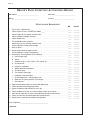
TABLE OF CONTENTS
SECTION
INTRODUCTION . . . . . . . . . . . . . . . . . . . . . . . . . . . . . . . . . . . . . . . . . . . . . . . . . . . . .1
EPA10 EXHAUST SYSTEM . . . . . . . . . . . . . . . . . . . . . . . . . . . . . . . . . . . . . . . . . . . .2
OPERATOR'S COMPARTMENT . . . . . . . . . . . . . . . . . . . . . . . . . . . . . . . . . . . . . . . . . .3
OPERATING THE VEHICLE . . . . . . . . . . . . . . . . . . . . . . . . . . . . . . . . . . . . . . . . . . . .4
EMERGENCY EQUIPMENT . . . . . . . . . . . . . . . . . . . . . . . . . . . . . . . . . . . . . . . . . . . . .5
GENERAL INFORMATION . . . . . . . . . . . . . . . . . . . . . . . . . . . . . . . . . . . . . . . . . . . . .6
MAINTENANCE . . . . . . . . . . . . . . . . . . . . . . . . . . . . . . . . . . . . . . . . . . . . . . . . . . . . .7
Page i
SAF-T-LINER® EFX OPERATOR’S MANUAL
Page ii
INTRODUCTION
TO THE OPERATOR
This manual has been prepared to acquaint you with
the necessary information for the proper operation of
your Thomas Bus body and chassis.
and illustrations will pertain to optional equipment.
Thomas Built Buses, Inc. reserves the right to make
changes at any time without notice.
A thorough knowledge of the operating controls is
essential to the proper transit and comfort of
passengers.
We would like to say "Thank You" for choosing the
Thomas product line to fill your transportation needs.
The information and illustrations contained in this
manual are based on the latest product information
available at the time of publication. Some procedures
This manual should remain with the vehicle when sold
to provide the next owner with important operation
and maintenance information.
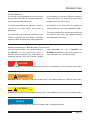
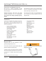
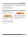
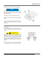
GENERAL INFORMATION - HAZARD ALERT TYPES & USES
Service literature includes a new type of hazard alert:
the NOTICE. This new hazard type allows a
distinction between potential injury, and property or
component damage, which were formerly grouped
under CAUTION. The use of DANGER and
WARNING hazard alerts are the same as before. For
more information, see each definition below.
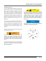
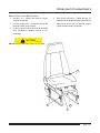
! DANGER
DANGER indicates an immediately hazardous situation which, if not avoided, will result in death or serious injury.
WARNING
WARNING indicates a potentially hazardous situation which, if not avoided, could result in death or serious injury.
CAUTION
CAUTION indicates a potentially hazardous situation which, if not avoided, could result in minor or moderate injury.
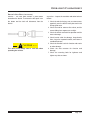
_______ NOTICE _______
NOTICE indicates a procedure that could cause property and / or equipment damage.
Page 1.1
SAF-T-LINER® EFX OPERATOR’S MANUAL
_______ NOTICE _______
Your Thomas Built Bus has been manufactured in
strict compliance with all the applicable Federal Motor
Vehicle Safety Standards (FMVSS) and Canadian
Motor Vehicle Safety Standards (CMVSS). We
strongly advise against making any changes or
modifications that will in any way violate this
compliance.
Thomas Built Buses will not be responsible for any
change or modification occurring to the vehicle after
its purchase that violates these FMVSS and Canadian
Motor Vehicle Safety Standards (CMVSS) standards.
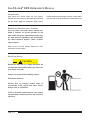
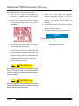
CALIFORNIA PROPOSITION 65 WARNING
WARNING
This product contains or emits chemicals known
to the State of California to cause cancer and birth
defects or other reproductive harm.
MODIFICATIONS OR ADDITIONS TO YOUR VEHICLE
Installation of additional or non-standard components
or attachments as well as alteration or removal of
components can adversely affect the safety or
performance of your vehicle.
Be sure to observe the limitation and specifications
set forth in your Operator’s Manual.
Page 1.2
WARNING
Engine Exhaust, some of its constituents, and
certain vehicle components contain or emit
chemicals known to State of California to cause
cancer and birth defects or other reproductive
harm.
INTRODUCTION
VEHICLE MODIFICATION DISCLAIMER POLICY
Thomas Built Buses, Inc. is not responsible for any
direct or indirect consequence of any modification or
alteration made to its products by anyone other than
the Thomas factory. Please be advised that such
modifications may VOID the Federal and/or State
Certification, and the Thomas Body and Chassis
warranty.
The limited warranties of Thomas exclude:
"Components or systems which have been altered
or modified without the express prior, written
authorization of the company."
Examples of such modifications are, but are not
limited to, the following:
• after-market alternate-fuel conversions
• chassis wheelbase changes
• mounting a Thomas body on a different chassis
than the original
• mounting a different body (than original) on a
Thomas chassis
• any component alteration that affects GAWRF,
GAWRR, and/or GVWR
• any component alteration that affects any FMVSS
certification
• power train replacement or alteration other than
original specification
• steering, braking, or suspension alteration other
than original specification
• seating capacity or configuration modification
• addition or deletion of any passenger entrance or
exit
• basic body structural alteration
• modification of the body-to-chassis mounting
system
• exhaust system alteration or replacement other
than original specification
• use of un-approved fluids, fuels, or lubricants
• electrical system/component alteration
• addition of after-market components, such as:
• Retarder
• Air conditioning
• Battery disconnect
• Traction devices
Page 1.3
SAF-T-LINER® EFX OPERATOR’S MANUAL
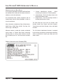
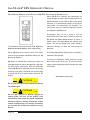
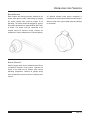
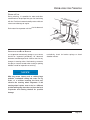
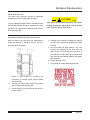
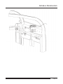
CERTIFICATION AND DATA PLATE
The computer generated Certification and Data Plates
are attached to the inside roof liner above the driver's
window or on the front bulkhead.
The Certification Plate certifies compliance with all
Federal Motor Vehicle Safety Standards in effect at
time of manufacture.
Other information included are Date of Manufacture,
GAWR Front, GAWR Rear, GVWR, Tire Data, VIN,
Vehicle Type, and Body ID.
Whenever contact is made with a dealer, authorized
service agent, or Thomas Built Buses concerning
warranty, parts, or service, these numbers must be
given to identify the unit. The three sets of numbers
are:
VEHICLE IDENTIFICATION NUMBER (VIN)
Page 1.4
1. Chassis Identification Number - When
concerning the chassis of a Thomas product.
2. Order Number - The first five-digit number in the
Body Identification number.
3. Body Number - The last seven-digit number in
the Body Identification number.
The Data Plate lists items such as Chassis Yard
Number, Model Year, Engine and Serial Number,
Transmission and Serial Number, Axles and Model
Numbers.
The VIN (Vehicle Identification Number) is assigned
by the chassis manufacturer and contains information
such as manufacturer, engine type, body style, and
order number.
INTRODUCTION
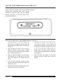
VEHICLE EMISSION CONTROL INFORMATION LABEL
Page 1.5
SAF-T-LINER® EFX OPERATOR’S MANUAL
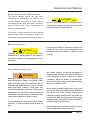
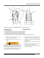
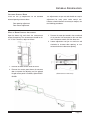
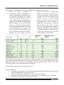
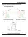
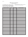
VEHICLE LOADING
The Thomas vehicle is designed to provide excellent
service if not loaded in excess of either the Gross
Vehicle Weight Rating (GVWR) or the maximum front
and rear Gross Axle Weight Rating (GAWR). These
ratings are listed on the vehicle certification plate with
the tires required to obtain these ratings.
GAWR (Gross Axle Weight Rating) is the maximum
weight the axle can carry and reflects the combined
capacity of axle, brakes, tires, wheel equipment, full
fuel burden included, and suspension.
Vehicle warranty is void on any vehicle which has
been subject to misuse. Overloading the vehicle is
misuse.
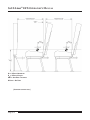
Vehicle Loading Example: Vehicle equipped with
standard axles and suspension, 10:00 x 20, Load
Range G or 11R22.5, Load Range G.
Rear GAWR
Front GAWR
GVWR
GVWR (Gross Vehicle Weight Rating) is the
maximum loaded weight of the vehicle. Passenger
and cargo loads should be distributed proportionately
over both the front and rear axles, full fuel burden
included, and sides of the vehicle.
CAUTION
Actual loads at the front and rear axles can only
be determined by weighing the vehicle at highway
weigh stations or other similar facilities.
21,200 lb.
12,000 lb.
________
33,200 lb.
Rear curb weight, cargo, and passenger load cannot
exceed 21,200 lb. (9616 kg.).
Front curb weight, cargo, and passenger load cannot
exceed 12,000 lb. (5479 kg.).
Maximum total weight cannot exceed 33,200 lb.
(15095 kg.).
(CONTINUES
ON NEXT PAGE.)
WARNING
Overloading can create the potential for serious
safety hazards and places excessive loads on
vehicle components.
REAR GAWR
Page 1.6
9616 kg.
5479 kg.
_______
15095 kg.
FRONT GAWR
INTRODUCTION
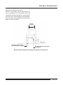
VEHICLE LOADING (CONTINUED)
CAUTION
Thomas Built Buses recommends that when an
MVP-EF requires towing, that it be towed from the
front whenever possible.
If the need arises for the unit to be towed from the
rear, the towing operator should make sure the
steer axle tires are rated high enough to support
the unit weight when towing from the rear. It is
also recommended that when towing from the rear
the distance towed is less than 30 miles at 45 mph.
DELIVERY INSPECTION - NEW VEHICLE
Each new Thomas bus has been inspected before
delivery. Every precaution has been taken to provide
the user with a complete and trouble-free bus.
There are certain steps that must be taken to continue
the assurance of a trouble-free bus. Proper inspection
and maintenance of the bus is a necessity from the
time of delivery and throughout its service life.
If the bus is not processed through a dealer before
delivery to the operator, the need to perform the
"Delivery Inspection" is greater. Any discrepancies or
omissions should be reported to the selling dealer
immediately.
Page 1.7
SAF-T-LINER® EFX OPERATOR’S MANUAL
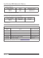
FIRST THIRTY DAYS
In addition to the Delivery Inspection, a one-time
preventive maintenance inspection should be
performed after the first thirty days of operation.
These are areas that should receive attention on any
new vehicle.
BODY
•
•
•
•
•
Tighten all mounting clips and bolts, then
retighten every six months thereafter.
Tighten all cowl mounting bolts, then retighten
every six months thereafter.
Tighten driver's seat bolts, then retighten every
six months thereafter.
Tighten seat leg and wall rail bolts, then
retighten every ninety days thereafter.
Tighten door control mounting bracket, then
retighten every six months thereafter.
•
•
•
Remove heater hose covers and tighten all
hose clamps.
Wash bus only with clean water for the first
thirty days.
Wax bus with a good automotive wax after the
first thirty days.
CHASSIS
•
•
•
•
•
•
•
•
•
•
•
•
•
•
•
•
Check toe-in. Reset if necessary.
Check the steering operation.
Tighten power steering items.
Check power steering reservoir level.
Clean and lubricate all fittings.
Inspect front and rear engine mounts and bolt
condition.
Tighten front and rear spring U-bolts.
Drain and refill differential lubricant.
Check transmission oil level. Drain and refill if
manual transmission.
Change engine oil and filters per PM schedule.
Tighten radiator hoses. Check coolant level.
Tighten steering gear mounting to frame.
Inspect tie rod, pitman arm, and drag link
connections.
Inspect for correct clutch adjustment, if
equipped.
Check brake master cylinder fluid level
(hydraulic brakes).
Inspect for correct brake adjustment.
Page 1.8
•
•
•
•
•
Adjust belt tension (all belts).
Tighten the After-Treatment Exhaust
System. Inspect for any damage to the
After-Treatment Device and the Mitigator
Device.
Gauge tires for correct air pressure.
Inspect for air leaks (air brake models).
Tighten all lug nuts (all wheels).
EPA10 EXHAUST SYSTEM
AFTERTREATMENT SYSTEM (ATS) PRINCIPLES OF OPERATION - CUMMINS
_______ NOTICE _______
EPA10 emissions regulations apply to vehicles
domiciled in Canada and the USA at the time of
printing this manual. Vehicles that are domiciled
outside of the USA and Canada may not have
EPA10-compliant engines with an emission
aftertreatment system, depending upon local
statutory emissions guidelines.
The EPA mandates that all engines built after
December 31, 2009 must reduce the level of
emissions exhausted by the engine to the following
levels:
Nitrogen Oxides (NOx) – 0.2 g/bhp-hr
Particulate Matter (PM) – .01 g/bhp-hr
To meet EPA guidelines, diesel engines installed in
Thomas Built Buses, Inc. chassis for domicile in
Canada and the USA use an Aftertreatment System
(ATS) with an Aftertreatment Device (ATD) and
Selective Catalytic Reduction (SCR) technology to
reduce NOx downstream of the engine.
CAUTION
Using non-specification fluids can result in
serious damage to the ATS. It is extremely
important that the following guidelines be
followed for vehicles with EPA10-compliant
engines, or damage may occur to the ATD, and the
warranty may be compromised.
•
•
•
•
Use ultralow-sulfur diesel with 15 ppm sulfur
content or less.
Do not use fuel blended with used engine lube
oil or kerosene.
Engine lube oil must have a sulfated ash level
less than 1.0 wt %; currently referred to as CJ4 oil.
Use only certified diesel exhaust fluid (DEF) in
the DEF tank
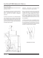
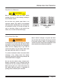
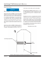
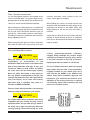
After exhaust gasses leave the engine, they flow into
the ATS. First they flow into a two-part ATD, comprised
of a diesel oxidation catalyst (DOC), and a Diesel
Particulate Filter (DPF). The DPF traps soot particles,
then exhaust heat converts the soot to ash in the DPF,
in a process called regeneration (regen). The harder
an engine works, the better it disposes of soot. When
the engine is running under load and regen occurs
without input, it is called passive regen. If the engine
isn’t running hot enough, the electronic controls may
initiate an active regen, whereby extra fuel is injected
into the exhaust stream before the diesel particulate
filter, to superheat the soot trapped in the filter and
burn it to ash. Both types of regen occur without driver
input.
! DANGER
Active regeneration can occur automatically any
time the vehicle is moving. The exhaust gas
temperature could reach 1500°F (800°C), which is
hot enough to ignite or melt common materials,
and to burn people. The exhaust can remain hot
after the vehicle has stopped moving.
Operating at reduced engine load will allow soot to
accumulate in the DPF. When this occurs, the DPF
lamp illuminates, indicating that a regen must be
performed, and the driver must either bring the vehicle
up to highway speed to increase the load, or park the
vehicle and initiate a parked regen. See Parked
Regen, later in this chapter for instructions.
After the exhaust stream passes through the ATD, it
flows through another canister housing, the SCR
device. A controlled quantity of diesel exhaust fluid
(DEF) is injected into the exhaust stream, where heat
converts it to ammonia (NH3) gas. This mixture flows
through the SCR device, where the ammonia gas
reacts with the NOx in the exhaust, to produce harmless nitrogen (N2) and water vapor (H2O), which then
exits out of the tailpipe.
Page 2.1
SAF-T-LINER® EFX OPERATOR’S MANUAL
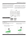
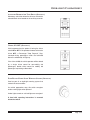
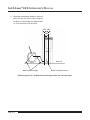
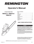
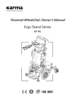
ATS WARNING LAMPS
The Malfunction Indicator Lamp (MIL) illuminates to
indicate a fault that affects the emissions. Figure 1
Warning lamps in the driver’s message center alert
the driver of situations with the aftertreatment system.
An illuminated DPF lamp indicates a regen is needed.
A slow, 10-second flashing of the Heat Exhaust
System Temperature (HEST) lamp alerts the driver
that a parked regen is in progress, but the exhaust
temperatures are still relatively cool. It also indicates
that the high-idle speed is being controlled by the
engine software, not the driver.
A steadily illuminated HEST lamp alerts the operator
of high exhaust temperatures when vehicle speed is
below 5 mph (8 km/h) while it is performing an
automatic regen, and during a parked regen.
FIGURE 1
An illuminated DEF warning lamp in the gauge,
indicates that the DEF tank should be refilled at the
next opportunity.
ATS PARKED REGENERATION
! DANGER
During
parked
regeneration,
exhaust
temperatures are very high, and could cause a
fire, heat damage to objects or materials, or
personal injury to persons near the exhaust
outlet.
_______ NOTICE _______
The regeneration switch can initiate a parked
regen only when the DPF lamp is illuminated
(because the engine software is signaling for a
parked regeneration.)
Before initiating a parked regeneration, make certain
the exhaust outlets are directed away from structures,
trees, vegetation, flammable materials, and anything
else that may be damaged or injured by prolonged
exposure to high heat.
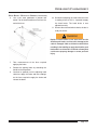
The regen-inhibit switch (optional when available)
provides additional control over the aftertreatment
regeneration process. Depressing the regenerationinhibit switch will prevent a regen from occurring
during a drive cycle. After the vehicle has been shut
down and restarted, regens will occur normally unless
the inhibit switch is pressed again. Figure 4
A reference label is included with the driver’s
documentation package that explains the ATS
warnings, and actions required to avoid further engine
protection sequences. Figure 2
To initiate a parked regeneration, perform the
following steps:
The optional regeneration switch, located on the dash,
is used to initiate a parked regeneration of the
aftertreatment device. Figure 3
warm the engine until the coolant temperature is
at least 150°F (66°C).
1. Park the vehicle away from all combustible and
flammable materials. Chock the tires. Start and
(CONTINUED
Page 2.2
ON NEXT PAGE.)
EPA10 EXHAUST SYSTEM
ATS PARKED REGENERATION (CONTINUED)
FIGURE 2
FIGURE 3
_______ NOTICE _______
The driver must remain with the vehicle during the
entire regeneration cycle.
2.
3.
Set the parking brake. If the parking brake was
already set, you must release it, then set it
again.
Press and hold the regeneration switch for 4
seconds. The engine will increase rpm and
initiate the regen process.
FIGURE 4
3.1 After the parked regen has run for 20 to 40
minutes, the regen cycle is completed. The
engine idle speed will drop to normal, and the
vehicle may be driven normally. The HEST
lamp may be illuminated, but will go out when
the vehicle speed exceeds 5 mph (8 km/h), or
the system has cooled to normal operating
temperature.
3.2 To stop a parked regen at any time during the
process, engage the clutch, brake, or throttle
pedal, or turn off the engine.
Page 2.3
SAF-T-LINER® EFX OPERATOR’S MANUAL
ATS DIESEL PARTICULATE FILTER (DPF) MAINTENANCE
Eventually ash will accumulate in the DPF and the
filter will require servicing. DPF servicing must be
performed by an authorized technician, following the
engine manufacturer’s instructions. A record must be
maintained for warranty purposes, that includes:
•
•
•
date of cleaning or replacement
vehicle mileage
particulate filter part number and serial number
DIESEL EXHAUST FLUID (DEF) - CUMMINS
DEF is used in the aftertreatment system to lower
NOx in the exhaust stream. DEF is colorless and
close to odorless. (It may have a slightly pungent odor
similar to ammonia.) It is nontoxic, non-flammable and
biodegradable. It is mildly corrosive to aluminum, but
it will not affect the strength or structure of the
aluminum. Constant DEF contact will result in white
powder residue. Around 12°F (-11°C) DEF freezes to
slush, but is not damaged or destroyed if frozen, and
is fully usable when thawed. The DEF supply lines are
electrically heated and are purged when the engine is
Page 2.4
shut down. At start up, normal operation of the vehicle
is not inhibited if the DEF is frozen; an immersion
heater with engine coolant flowing through it will warm
the DEF once the engine is running, to allow the SCR
system to operate.
EPA10 EXHAUST SYSTEM
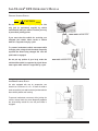
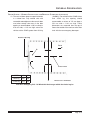
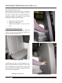
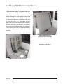
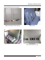
DEF TANK, LOCATION AND FILLING REQUIREMENTS
On the MVP-EFX, the tank is located on the right side,
rearward of the front entrance door. The DEF tank has
a 19 mm filler neck inlet that prevents the hose from a
diesel outlet from being inserted, and has a blue cap
for easy identification.
The MVP-EFxX School Bus has a 10-gallon tank
capacity. DEF consumption is approximately 2% of
fuel consumption, dependent on vehicle operation.
For every 50 gallons of diesel fuel consumed,
approximately 1 gallon of DEF will be consumed.
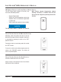
DEF TANK FILL ACCESS DOOR
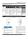
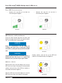
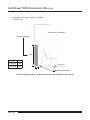
FUEL / DEF GAUGE
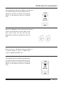
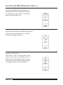
The DEF levels are measured by a gauge consisting
of a four segment LED bar graph.
•
•
Between 50% and 75% full, three bars are
illuminated green. Figure 6
Between 75% and 100% full, four bars are
illuminated green. Figure 5
FIGURE 6
FIGURE 5
(CONTINUED
ON NEXT PAGE.)
Page 2.5
SAF-T-LINER® EFX OPERATOR’S MANUAL
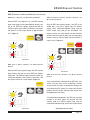
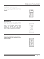
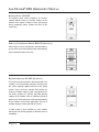
FUEL / DEF GAUGE (CONTINUED)
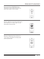
•
Between 25% and 50% full, two bars are
illuminated green. Figure 7
FIGURE 7
•
Between 10% and 25% full, one bar is
illuminated green. Figure 8
FIGURE 8
DEF WARNINGS AND ENGINE DERATES
There are safety controls that warn the driver and
derate the engine when the DEF level registers below
10%, or if the DEF tank is contaminated.
_______ NOTICE _______
Under no circumstances will the engine be
suddenly shut down due to running the vehicle
out of DEF, or putting the improper fluid in the DEF
tank.
_______ NOTICE _______
Tampering with any portion of the DEF system, or
diluting the fluid, will result in a system fault
detection, and a possible major engine derate.
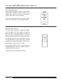
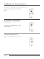
FIGURE 9
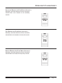
flashing (amber), and one bar of the DEF-level
lightbar is illuminated flashing red. Figure 10
DEF LEVEL—WARNING
When the DEF level in the tank drops to 10% full, the
DEF Low Level Lamp in the gauge is illuminated solid
(amber), and one bar of the DEF-level lightbar is
illuminated solid amber. Figure 9
When the DEF level in the tank drops to 5% full, the
DEF Low Level Lamp in the gauge is illuminated
Page 2.6
FIGURE 10
EPA10 EXHAUST SYSTEM
DEF WARNINGS AND ENGINE DERATES (CONTINUED)
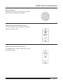
DEF LEVEL—WARNING AND MINOR ENGINE DERATE
When the DEF level drops to 2.5%, the DEF warning
lamp in the gauge is illuminated flashing (amber), one
bar of the DEF-level lightbar flashes red and the
CHECK engine lamp (amber) illuminates. The engine
will perform a minor torque derate of approximately
25%. Figure 11
CHECK ENGINE
DEF TANK-EMPTY WARNING IGNORED—WARNING
MAJOR ENGINE DERATE
AND
After the DEF tank registers empty, if the DEF is not
refilled after a fuel fill or engine stop, the CHECK
engine lamp, malfunction-indicator lamp, and the
STOP engine lamp (red) will be illuminated. The
engine remains at a minor derate until the electronic
sensors indicate a safe situation, then a major engine
derate will occur. (Vehicle speed may be limited to 5
mph /8 km/h.) Figure 13
CHECK ENGINE
STOP ENGINE
FIGURE 11
DEF TANK
DERATE
IS
EMPTY—WARNING
AND
MINOR ENGINE
When the DEF tank registers empty, the DEF warning
lamp flashes, and one bar of the DEF-level lightbar
flashes red. The CHECK engine lamp illuminates, the
malfunction-indicator lamp (amber) illuminates, and
the engine remains at a minor derate. Figure 12
CHECK ENGINE
FIGURE 13
DEF CONTAMINATED—WARNING
DERATE
AND
MAJOR ENGINE
Once a contaminant is detected in the DEF tank, your
vehicle must be taken to an authorized Cummins
service center to ensure no permanent damage has
occurred to the SCR system, the system will function
properly with the correct reducing agent and to reset
the appropriate fault codes.
If a contaminant is detected in the DEF tank, the NOx
sensors in the SCR system will activate the DEF
warning lamp, the CHECK engine lamp, and the
malfunction-indicator lamp, and a minor engine derate
FIGURE 12
(CONTINUED
ON NEXT PAGE.)
Page 2.7
SAF-T-LINER® EFX OPERATOR’S MANUAL
DEF WARNINGS AND ENGINE DERATES (CONTINUED)
will occur. After driving 20 hours or 1000 miles (1600
km) without remedy, the STOP engine lamp will
illuminate, and a major engine derate will occur as
soon as the electronic sensors indicate a safe
situation
After the DEF tank is refilled with DEF, and the
SCR system senses proper NOx levels, the engine
will return to normal operation.
Page 2.8
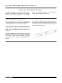
EPA10 EXHAUST SYSTEM
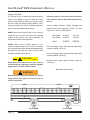
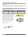
EXHAUST SYSTEM INSPECTING (NOISE EMISSION CONTROL)
The exhaust system must be free of leaks, binding,
grounding, and excessive vibrations. In addition to
inspecting the exhaust system at the scheduled
maintenance interval, inspect the exhaust system if
the noise level of the vehicle has increased. Replace
parts that show leakage, wear, or damage, with
genuine Freightliner/Thomas parts.
These conditions are usually caused by loose,
broken, or misaligned clamps, brackets, or pipes.
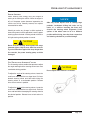
EPA10 EXHAUST SYSTEM - DEFINITIONS OF AFTERTREATMENT SYSTEM (ATS) TERMS
Refer to the following list of definitions of ATS terms
and components.
•
•
•
•
•
•
•
•
Aftertreatment System (ATS)—the entire
exhaust system from the turbocharger to the
tail pipe, including the Selective Catalytic
Reduction (SCR) components.
Aftertreatment Device (ATD)—a device that
removes pollutants from exhaust gas after the
gas leaves the combustion chamber.
BlueTec®—Daimler’s proprietary SCR
technology.
Diesel Oxidation Catalyst (DOC)—a flowthrough devise that enhances the oxidation of
hydrocarbons in the ATD.
Diesel Particulate Filter (DPF)—a component
in the ATD that traps particulate matter from
the exhaust gas.
Diesel Exhaust Fluid (DEF)—the chemical
agent that reacts with the exhaust gases in
the SCR to reduce NOx.
•
•
•
•
DEF Pump—filters and supplies DEF to the
DEF metering unit.
DEF Tank—holds DEF and regulates its
temperature.
DEF Metering Unit—mixes DEF with
compressed air, and meters this mixture into
the exhaust flow via an injection nozzle.
SCR Catalyst—the housing containing a
treated ceramic flow-through block where the
DEF and exhaust gases undergo selective
catalytic reduction.
Selective Catalytic Reduction (SCR)—a
process used to reduce NOx emissions.
Engine Derate—when the engine power is
reduced by 25% to protect the engine. This
warns the driver that the DEF level registers
below 10% or if the DEF tank is
contaminated.
Page 2.9
SAF-T-LINER® EFX OPERATOR’S MANUAL
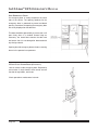
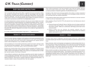
INSPECTION
_______ NOTICE _______
The Environmental Protection Agency’s 2010
regulations mandate lowered exhaust emissions,
thus requiring exhaust system components that
reduce emissions. In particular the aftertreatment
device (ATD), which is part of the aftertreatment
system (ATS), requires special attention during
regularly scheduled maintenance inspections.
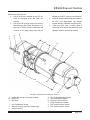
See Figure 1 for Cummins ATD sensor locations. If
any discrepancies are discovered, refer to the
engine manufacturer’s service literature for repair
instructions.
1.
2.
3.
4.
5.
6.
Check for leakage at the clamp that attaches
the exhaust pipe to the turbocharger exhaust
outlet. If leakage exists, tighten the nut on the
clamp to the required torque. If leakage
persists, install a new clamp.
Check the exhaust pipe, bellows, and each
exhaust seal clamp for leakage, wear, cracks,
or damage. Replace damaged components
as needed. If leakage exists at a clamp,
tighten the nuts to the required torque. If
leakage persists, install a new exhaust seal
clamp. Do not reuse seal clamps. Once a
seal clamp is loosened or removed, it must
be replaced.
If present, check the condition of the
insulation material around the exhaust pipe
between the turbocharger and the ATD.
Check the ATD mounting bands for tightness.
Tighten to 30 lbf•ft (41 N•m) if needed. Do not
overtighten.
Check for leaks around the clamps that
attach the ATD in the ATS, and around the
clamps that retain the DPF in the ATD. No
leaks are allowed anywhere in the system.
Check all sensors attached to the ATD for
leaks or damaged wires. No leaks are
allowed.
Page 2.10
7.
8.
9.
Check the DPF exterior surface for dents or
other damage. A dent over 3 inches (76 mm)
in diameter and 1/4-inch (6-mm) deep could
cause internal damage to the DPF, causing it
to malfunction.
Check the SCR catalyst for dents and other
damage.
Check for heat discoloration on the surface of
the ATD. Heat discoloration may indicate
internal damage; especially around the DPF.
_______ NOTICE _______
Diesel exhaust fluid creeps, causing white
crystals to form around the line fittings.
The presence of crystals does not mean the system
has a leak. Replacing the fittings or troubleshooting
the components is not necessary unless there is a
system failure or a fault code.
10. Check the DEF tank, pump, metering unit,
and lines for leaks.
11. Check any wires, lines, or hoses within 4
inches (10 cm) of the exhaust system for heat
damage. Repair or reroute as needed.
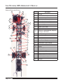
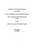
EPA10 EXHAUST SYSTEM
INSPECTION
9
7
8
10
6
3
1
2
4
5
FIGURE 1 - CUMMINS ATD SENSOR LOCATIONS
1.
2.
3.
4.
5.
6.
DOC INLET TEMPERATURE SENSOR
DOC OUTLET TEMPERATURE SENSOR
DPF OUTLET TEMPERATURE SENSOR
DPF TEMPERATURE SENSOR INTERFACE
DPF PRESSURE SENSOR INTERFACE
DOSER INTERFACE
7.
8.
9.
10.
SCR INLET TEMPERATURE SENSOR
SCR TEMPERATURE SENSOR
OUTLET NOX SENSOR
SCR OUTLET TEMPERATURE SENSOR
Page 2.11
SAF-T-LINER® EFX OPERATOR’S MANUAL
DIESEL EXHAUST FLUID (DEF) FILTER
The Environmental Protection Agency's 2010
regulations require lower nitrogen oxide (NOx)
exhaust emissions. Selective catalytic reduction
(SCR) uses diesel exhaust fluid (DEF) to lower NOx
emissions in the vehicle exhaust. A filter in the DEF
pump prevents clogging of the DEF metering unit
injection nozzle.
EPA07 EXHAUST SYSTEM - DEFINITIONS OF ATS COMPONENTS
Refer to the following list of definitions of ATS terms
and components.
•
•
Aftertreatment System (ATS)—the entire
exhaust system from the turbocharger to the
exhaust stack or tail pipe.
Aftertreatment Device (ATD)—the muffler-like
canister that houses a DPF and sensors.
•
•
•
Diesel Particulate Filter (DPF)—a filter that
collects and holds particulate matter (soot
and ash).
Diesel Oxidation Catalyst (DOC)—oxidizes
hydrocarbons and reduces NOx.
Sensors—detect temperatures and pressure
within the ATS.
INSPECTION
_______ NOTICE _______
The Environmental Protection Agency's 2007
regulations require lower exhaust emissions, thus
requiring new exhaust system components. (See
Figure 2.) In particular, the aftertreatment device
(ATD), which is part of the aftertreatment system
(ATS), requires special attention during regularly
scheduled maintenance inspections. If any
discrepancies are discovered, refer to the engine
manufacturer's service literature for repair
instructions, or take the vehicle to an authorized
Freightliner or Thomas Built Bus service facility
for repair.
1.
2.
Check for leakage at the clamp that attaches
the exhaust pipe to the turbocharger exhaust
outlet. If leakage exists, tighten the nut on the
clamp to the required torque. If leakage
persists, install a new clamp.
Check the exhaust pipe and each exhaust
seal clamp for leakage, wear, cracks, or
Page 2.12
3.
4.
5.
damage. Replace damage components as
needed. If leakage exists at the clamp,
tighten the nuts to the required torque. If
leakage persists, install a new exhaust seal
clamp. Do not reuse seal clamps. Once a
seal clamp is loosened or removed, it must
be replaced.
If present, check the condition of the
insulation material around the exhaust pipe
between the turbocharger and the ATD.
Check the ATD mounting bands for tightness.
Tighten to 30 lbf-ft (41 M-m) if needed. Do not
overtighten.
Check for leaks around the clamps that
attach the ATD in the ATS, and around the
clamps that retain the DPF in the ATD. No
leaks are allowed anywhere in the system.
(CONTINUED
ON NEXT PAGE.)
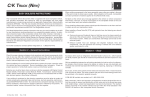
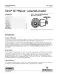
EPA10 EXHAUST SYSTEM
INSPECTION (CONTINUED)
6.
7.
Check all sensors attached to the ATD for
leaks or damaged wires. No leaks are
allowed.
Check the DPF exterior surface for dents or
other damage. (See Figure 2,Reference A.) A
dent over 3 inches (76 mm) in diameter and
1/4-inch (6 mm) deep could cause internal
2
8.
9.
damage to the DPF, causing it to malfunction.
Check for heat discoloration on the surface of
the ATD. Heat discoloration may indicate
internal damage; especially around the DPF.
Check any wires, lines, or hoses within 4
inches (10 cm) of the exhaust system for heat
damage. Repair or re-route as needed.
3
1
5
B
4
C
4
9
A
8
7
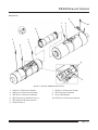
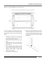
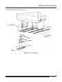
FIGURE 2- AFTERTREATMENT DEVICE (TYPICAL)
A. Inspect this area of the canister for dents.
B. DOC Area
C. DPF Area
1.
2.
3.
Inlet Temperature Sensor
Marmon Fitting at Inlet from Turbocharger
Sensor Housing
4..
5.
6.
7.
8.
9.
6
DPF V-Band Mounting Clamps
Inlet Temperature Sensor
Exhaust Outlet to Diffuser
Outlet Temperature Sensor
DPF Outlet Pressure Sensor
DPF Intake Pressure Sensor
Page 2.13
SAF-T-LINER® EFX OPERATOR’S MANUAL
Page 2.14
OPERATOR'S COMPARTMENT
This section provides the operator with important
operational and general information. The following
divides the Operator's Compartment into four major
parts. The first part of this section covers the
Instrument Panel, the second part covers the Side
Console Switch Panel, the Operator's Compartment
Controls forms the third part, and information about
the Driver's Seat completes the section.
It is important to carefully read and understand the
following pages before operating the vehicle. A proper
understanding of component location, function, and
operation is important to the proper operation of the
bus.
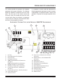
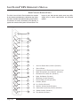
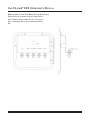
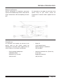
INSTRUMENT CONTROL UNIT, WITH OPTIONAL 3000 PTS TRANSMISSION
4
3
5
6
2
1
3
18
22
21
3
17
20
18
19
1.
2.
3.
4.
5.
AIR VENT
HEATER/DEFROSTER FAN CONTROL
SWITCH BLANKS
AIR PRESSURE GAUGE
3000 TRANSMISSION KEYPAD CONTROLLER
(OPTIONAL)
2500 TRANSMISSION SHIFTER (OPTIONAL)
6. EPA10 INSTRUMENT CLUSTER (DIESEL)
7. ATD MANUAL REGEN SWITCH (OPTIONAL)
8. CRUISE CONTROL SWITCH, SET/RESUME
(OPTIONAL)
9. CRUISE CONTROL SWITCH, ON-OFF (OPTIONAL)
10. PANEL DIMMER SWITCH
11. HEADLIGHT SWITCH
11
15
16
14
13
10
12
3
7
3
8
9
3
3
12. PILOT LIGHT, W/ WARNING LIGHT SYMBOL
(OPTIONAL)
13. WARNING SWITCH, ON-OFF-AMBER LED
(OPTIONAL)
14. DOOR SWITCH
15. WIPER/WASHER SWITCH
16. PARK BRAKE VALVE (AIR BRAKES)
17. IGNITION SWITCH
18. REAR (PASSENGER) HEATER SWITCH
19. REMOTE MIRROR CONTROLS
20. RADIO (OPTIONAL)
21. LEFT HEATER SWITCH
22. BOOSTER PUMP
Page 3.1
SAF-T-LINER® EFX OPERATOR’S MANUAL
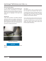
DRIVER'S AIR VENT
Located on the dash at the driver’s window and
directs air from the defrosters to the driver's side
glass.
ELECTRONIC HEATER / DEFROSTER CONTROLLER
The heater control panel enables the operator to
control the dash heating system by adjusting the
temperature setting and the fan speed.
SWITCH BLANKS
Blank panels are used to fill in openings in the switch
panel where switches are not used.
Page 3.2
OPERATOR'S COMPARTMENT
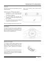
AIR PRESSURE GAUGE
The air pressure gauge indicates the levels of air
pressure in the primary or rear axle brake system
(green needle). (An optional secondary or front axle
brake system, red needle, is available.) If you have
dual air pressure gauges, they should indicate the
same pressure reading. Common cut-out pressures
are between 105-125 psi (72-86 kPa). Common cut-in
pressures are between 90-105 psi (62-72 kPa). The
pressure range between cut-in and cut-out is not
adjustable.
The rear brakes will gradually begin to apply when air
pressure drops below 65 psi (45 kPa). At 40 psi (28
kPa) the rear brakes will automatically lock up by
actuating the PP-1 valve and allowing the air in the
spring brake side of the brake chamber to be
released.
CAUTION
If one needle suddenly drops pressure and stays
below 65 psi (448 kPa), the other system can still
safely stop the vehicle, but it may take longer,
stopping distances may be increased, and the
brakes can only be applied a limited number of
times. Have the vehicle repaired immediately if
this occurs.
_______ NOTICE _______
On Hydraulics units, a single needle air gauge is
installed for air-operated accessories.
Determine and correct cause of pressure loss before
returning vehicle to service.
WARNING
In the event that a pressure loss occurs, the
operator can identify the affected system by
observing the gauge needles. Stop the vehicle
immediately if either of the following conditions
occur:
Lower air warning buzzer sounds and/or indicator
light comes on when the air pressure drops below
60-72 psi (41-50 kPa).
Page 3.3
SAF-T-LINER® EFX OPERATOR’S MANUAL
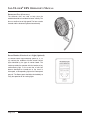
TRANSMISSION SHIFTER, WITH OPTIONAL 3000 PTS TRANSMISSION (PUSHBUTTON)
When *(D) Drive is selected, the transmission will
initially engage the lowest gear programmed for the
(D) Drive position, usually (1) First gear. As the speed
increases, it will automatically upshift. As the vehicle
slows down, the transmission will downshift. The
vehicle must come to a complete stop before shifting
from (D) Drive to (R) Reverse.
The pushbutton shift selector has R, N, D, Up Arrow,
Down Arrow, Mode Button, and a digital display.
Select *(R) Reverse to back the vehicle. The vehicle
must come to a complete stop before shifting from (R)
Reverse to (D) Drive.
(N) Neutral is selected when starting the engine, for
extended periods of engine idle operation, and when
checking vehicle accessories. With the pushbutton
selector (N) Neutral is selected by the ECU at start-up,
unlike the lever shifter. This button has a raised edge
to enable the driver to touch without looking at the
display.
CAUTION
Do not race the engine when shifting from Neutral
into another gear.
CAUTION
Set the gear selector to Neutral, engage the
parking brake, and turn off the ignition, even
momentarily. Never leave the vehicle unattended
while the engine is running. Unexpected sudden
vehicle movement may occur if these precautions
are not taken. Do not allow the vehicle to coast in
Neutral.
Page 3.4
Occasionally there will be a need to limit the
transmission to the lower gears. To do this, utilize the
Up Arrow and Down Arrow buttons to select a
specific range. The digital display will Indicator your
choice. This will not change until vehicle speed is
reduced sufficiently to allow the transmission to
downshift.
The Display Mode button allows the driver to enable a
secondary shift schedule.
To access the Diagnostic Codes, press the up and
down arrows at the same time. To clear active fault
codes, hold the mode button three seconds until mode
LED flashes.
(CONTINUED
ON NEXT PAGE.)
OPERATOR'S COMPARTMENT
TRANSMISSION SHIFTER, WITH OPTIONAL 3000 PTS TRANSMISSION (PUSHBUTTON) (CONTINUED)
The Display Mode button allows the driver to enable a
secondary shift schedule.
_______ NOTICE _______
To access the Diagnostic Codes, press the up and
down arrows at the same time. To clear active fault
codes, hold the mode button three seconds until mode
LED flashes.
*(R) Reverse or (D) Drive position may be
prevented when a damaging or undesirable range
engagement would occur due to a vehicle logic or
engine speed condition.
CAUTION
For more information, refer
Transmission Operator's Manual.
to
your
Allison
Never depend on the transmission as an engine
brake. The transmission will upshift, no matter
what gear is selected when the internal pressure
reaches a certain level. A shift point will be created
by high engine rpm.
Page 3.5
SAF-T-LINER® EFX OPERATOR’S MANUAL
TRANSMISSION SHIFTER, WITH OPTIONAL 2500 PTS TRANSMISSION (LEVER)
( D ) Overdrive - For most highway driving.
(D) Drive - For most city driving.
(2) Second - For driving slowly in heavy city traffic or
on mountain roads where more precise speed control
is desirable, and for climbing and descending long
grades.
To prevent excess engine speed, do not exceed 45
mph (72 kph) in this gear.
To put the transmission into gear, move the selector
lever from Neutral to the desired drive position.
CAUTION
Do not race the engine when shifting from Neutral
into another gear.
The available gears are:
(R) Reverse - Vehicle must be completely stopped
before engaging this gear.
(N) Neutral - Use when vehicle is standing for
prolonged periods with engine running. Set the
parking brake if you leave the vehicle. Engine may be
started in this gear.
CAUTION
Set the gear selector to Neutral, engage the
parking brake, and turn off the ignition, even
momentarily. Never leave the vehicle unattended
while the engine is running. Unexpected sudden
vehicle movement may occur if these precautions
are not taken. Do not allow the vehicle to coast in
Neutral.
Page 3.6
(1) First - For driving up very steep hills and engine
braking at low speeds - 25 mph (40 kph) or less when going downhill.
To prevent excessive engine speed, do not exceed 25
mph (40 kph) in this gear.
A red indicator light will illuminate if the transmission is
unable to shift at the appropriate time. This indicates
a failure in the transmission and should be checked by
a qualified technician. Pull the bus over to a safe
location and get assistance.
CAUTION
Never depend on the transmission as an engine
brake. The transmission will upshift, no mater
what gear is selected when the internal pressure
reaches a certain level. A shift point will be created
by high engine rpm.
OPERATOR'S COMPARTMENT
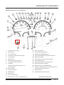
EPA10 INSTRUMENT CLUSTER (DIESEL)
3
5
4
6
7
10
8
9
12
13
14
15
16
11
17
2
18
1
28
19
27
26
20
25
24
21
23
22
1.
2.
3.
4.
TACHOMETER (OPTIONAL)
MAINTENANCE
LEFT TURN SIGNAL
HIGH EXHAUST SYSTEM TEMPERATURE
16.
17.
18.
19.
5.
6.
7.
8.
9.
CHECK ENGINE
STOP ENGINE
MALFUNCTION INDICATOR LAMP
TRANSMISSION RETARDER ACTIVE
AIR BRAKE
HYDRAULIC BRAKE (DEPENDING ON UNIT
CONFIGURATION)
WAIT TO START
TRACTION CONTROL
ABS WARNING
SHIFT INHIBIT
CHECK TRANSMISSION
DIESEL PARTICULATE FILTER REGENERATION
20.
21.
22.
23.
24
25.
26.
10.
11.
12.
13
14.
15.
RIGHT TURN SIGNAL
FASTEN SEAT BELT WARNING
SPEEDOMETER (MPH & METRIC)
HIGH TRANSMISSION TEMP INDICATOR & GAUGE
MAINTENANCE MENU
HIGH COOLANT TEMP INDICATOR & GAUGE
CRUISE CONTROL ON
LOW OIL PRESSURE INDICATOR & GAUGE
DASH DRIVER DISPLAY SCREEN
DIESEL EXHAUST FLUID (DEF) GAUGE
LOW FUEL INDICATOR & FUEL LEVEL GAUGE (ULTRALOW SULFUR DIESEL FUEL ONLY)
27. PARKING BRAKE
28. HIGH BEAM HEADLIGHT INDICATOR
(CONTINUED
ON NEXT PAGE.)
Page 3.7
SAF-T-LINER® EFX OPERATOR’S MANUAL
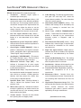
EPA10 INSTRUMENT CLUSTER (CONTINUED)
1.
Tachometer - Indicates engine speed in
revolutions per minute (rpm).
2. Maintenance Intervals Indicator (Yellow) - Will
activate when either of the following conditions
have been met: The oil change interval has been
met and the "change air filter" input has been set
low. This menu allows the driver to set the
change intervals. The maintenance warnings
must be disabled if the intervals are set to zero.
3. Left Turn Signal Indicator Lamp (Green) Indicates that the driver intends to turn left and
flashes at a rate determined by the flasher
module.
4. High Exhaust System Temperature (HEST) Alerts the driver that the exhaust temperature is
out of the desired range.
5. Check Engine ("CHECK ENGINE") - When a
problem is detected by the engine's electronic
system, a diagnostic code is generated and the
"Check Engine" lamp is turned ON.
6. Stop Engine ("STOP ENGINE") - (This acts as
the "Engine Warning" Lamp.) - The bus will shut
down in 30 seconds after light illuminates.
7. Malfunction Indicator Lamp (MIL) - The
indicator is illuminated for all active engine
emission related faults including but not limited
to after-treatment devices.
8. Retarder Active Lamp - Lamp illuminates when
the transmission retarder is engaged. It serves to
slow vehicles or maintain a steady speed on
declines, and help prevent the vehicle from
running away on downhill declines.
9. Hydraulic Brake Fault - Warning indicator is
used to indicate that hydraulic brake fluid
pressure is low.
10. Wait to Start (Optional) - Indicates to the driver
turning the ignition key, he needs to wait a few
moments with the key in the accessory position
before cranking the ignition.
11. Traction Control - Prevents the drive wheels
from spinning when on slippery roads.
Page 3.8
12. A.B.S. Warning - The warning lamp blinks once,
then goes OFF and stays OFF, unless the
system detects a problem. For more information
refer to the service manual.
13. Shift Inhibit ("SHIFT INHIBIT") (Yellow) - The
indicator and message will be activated by the
ICU if a message is received from the
transmission.
14. Check Trans ("CHECK TRANSMISSION")
(Amber) - Transmission Fault indicator. When a
problem is detected by the transmission's
electronic system, a diagnostic code is
generated.
15. Diesel Particulate Filter (DPF) (Yellow) - Lamp
indicates that a manual regen is required soon,
and should be scheduled for the earliest
convenient time.
16 Right Turn Signal Indicator Lamps (Green)Indicates that the driver intends to turn right and
flashes at a rate determined by the flasher
module.
17. Fasten Seat Belt Warning (Red) - The warning
light (seat belt icon) illuminates for 15 seconds
after the ignition switch is turned on.
18. Speedometer - Indicates vehicle speed in miles
per hour (mph) and kilometers per hour (kph).
19. Transmission Fluid Temperature (Optional) Indicates the temperature of oil in the
transmission.
20. Maintenance Menu - Contains three submenus: Maintenance Intervals, Transmission Oil
Life remaining and Transmission Oil Filter Life
Monitor.
21. High Coolant Temperature Gauge (Red) - The
warning light (thermometer icon) and emergency
buzzer activate whenever the coolant
temperature goes above a preset maximum
specified by the engine manufacturer.
(CONTINUED
ON NEXT PAGE.)
OPERATOR'S COMPARTMENT
EPA10 INSTRUMENT CLUSTER (CONTINUED)
22. Cruise Control ("CRUISE ON") (Green) - The
indicator (or message) will be activated by the
ICU when the associated input is activated.
23. Low Engine Oil Pressure ("LOW OIL
PRESSURE") - Indicates the oil pressure in the
engine is low.
24. Display Message Menu Screen - The display
messages menu should contain the following
configurable categories:
a.
b.
c.
d.
e.
f.
g.
h.
i.
j.
k.
l.
m.
n.
o.
Odometer
Chassis Battery Voltage
Instantaneous Fuel Economy
Average Fuel Economy
Gear Attained Status
Transmission Temperature
Hour Meter
Trip Odometer 1
Trip Odometer 2
Boost Pressure
Engine RPM
Percent Engine Load
Fuel Level
Coolant Temperature
Engine Oil Pressure
The display messages menu has three visible lines.
The top line displays the odometer and chassis
battery voltage, while the second and third lines
display other driver selectable parameters. The lines
can be adjusted to show any of the optional display
messages. The menu configuration will be stored in
the EE-prom upon key off.
25. Diesel Exhaust Fluid (DEF) Gauge - Refer to
EPA10 Exhaust System section for operation.)
26. Low Fuel Level Gauge ("LOW FUEL") (UltraLow Sulfur Diesel Fuel only) - Indicates the
amount of fuel in the tank.
27. Park Brake On Indicator (Red) - The
warning/parking brake on indicator light (BRAKE
legend) activates whenever the parking brake is
engaged. If the vehicle is moving at a speed of 2
mph (3 km/h) or more, the emergency buzzer will
sound until the parking brake is released.
28. High Beam Headlight Indicator (Blue) Indicator light (sideways beam icon) illuminates
when the headlight high beams are on.
Page 3.9
SAF-T-LINER® EFX OPERATOR’S MANUAL
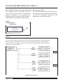
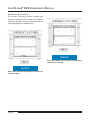
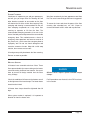
DISPLAY MESSAGE SCREEN (OPERATING EXAMPLE FOR MAINTENANCE MENU)
The maintenance menu shall contain three sub
menus. These three sub menus are maintenance
intervals, transmission oil life remaining, and
transmission oil filter life monitor. A fourth sub menu is
needed for older, pre-2010 service version clusters.
The maintenance intervals menu allows the driver to
set the change intervals of the Engine Oil and Engine
Air Filter. The maintenance warnings must be
disabled if the intervals are set to zero.
Screen 1
Auxiliary Screens
-Maintenance
Maintenance Screens are next.
Screen 2
Maintenance Screens
There are a minimum of two maintenance screens. In select cases depending on the vehicles transmission
type, you may see four maintenance screens. In this case the cluster S/W receives a message from the
engine "ECU and the transmission maintenance screen are then activated. Otherwise only the two default
maintenance screens are available.
DEFAULT
OPTIONAL
(CONTINUED
Page 3.10
ON NEXT PAGE.)
OPERATOR'S COMPARTMENT
DISPLAY MESSAGE SCREEN (OPERATING EXAMPLE FOR MAINTENANCE MENU) - CONTINUED
Screen 3
Auxiliary Screens
-Maintenance.......Engine Oil
To set the interval for engine oil changes, use the down button to scroll to ENGINE
OIL in the maintenance menu. to select ENGINE OIL, press the Right button.
Screen 4
Auxiliary Screens
-Maintenance.......Engine Oil
To change the interval to 6000 miles, continue to press the Down button.until 6000
miles is selected.
Page 3.11
SAF-T-LINER® EFX OPERATOR’S MANUAL
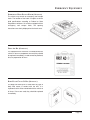
DPF (DIESEL PARTICULATE FILTER) MANUAL REGEN SWITCH
The DPF Regen Switch located on the dash, may
have three selectable positions:
•
•
•
Request Regeneration
Default (can include appropriate normal state
condition, either in an automatic regeneration
or inhibit state.
Inhibit regeneration (optional when available)
_______ NOTICE _______
The DPF Regen Switch is standard. An optional,
CRUISE CONTROL SWITCH, SET/RESUME (OPTIONAL)
Momentary switch that allows the driver to set the
desired vehicle speed. When this speed is reached, it
is maintained by pressing the switch to the "SET"
position to lock in.
Touching the brake or accelerator pedal will override
the "SET" function.
To return the vehicle to the desired speed, press the
switch to the "RESUME" position. The vehicle will
return to its preset speed.
CRUISE CONTROL SWITCH, ON-OFF (OPTIONAL)
Activates or deactivates the cruise control.
Switch must be in "ON" position for the Cruise Control
Set/Resume Switch to operate.
Page 3.12
Omit Exhaust System Regeneration Switch
(shorting connector) is installed under the left
dash next to the diagnostic port that performs this
function.
OPERATOR'S COMPARTMENT
PANEL DIMMER SWITCH (OPTIONAL)
Enables the driver to dim or brighten the light on the
dash panel by sliding the button to the desired
brightness.
HEADLIGHT SWITCH
The headlight switch is a three position switch that
controls the main lighting circuit. Position 1, lower
position is the OFF position. Position 2 center
energizes
the
parking
lights,
tail
lights,
marker/clearance lights, instrument and panel lights.
Position 3, upper position energizes the headlights.
PILOT LIGHT, WITH WARNING LIGHT SYMBOL
Amber and red flashing lights coordinated with eightlight warning system.
Page 3.13
SAF-T-LINER® EFX OPERATOR’S MANUAL
EIGHT LIGHT WARNING
Eight-light warning system controls the amber and red
warning lights mounted on the four corners of the
exterior of the vehicle. These lights are activated at
various times by the driver as necessary.
This system requirements vary from state to state.
Follow your state requirements for proper operation.
DOOR CONTROL SWITCH
The electric door control switch controls the operation
of the front door. In the lower position the entrance
door is closed. In the upper position the door will
open. This switch is connected directly to the battery
allowing entrance and exit of the vehicle at all times.
The operator should ensure that the door is closed
when shutting down the vehicle and leaving it parked.
If ignition key is turned off and door switch is left in
open position, an alarm buzzer will sound.
An emergency release valve is mounted over the
windshield beside the door which allows the door to
be opened without air pressure.
Air doors have two or three postion switches.
Page 3.14
OPERATOR'S COMPARTMENT
WINDSHIELD WIPER/WASHER CONTROL AND INDICATOR
Electric windshield wiper/washer is standard. The
electric windshield wiper/washer controls the wipers.
The wiper knob is located on the lower right dash. The
wiper control is a multi-position switch, which operates
clockwise, OFF, INTERMITTENT, LOW, HIGH.
To activate the windshield washers, press the wiper
knob. The washers will operate on both wet arms. Wet
arms provide for the washer fluid to be plumbed to the
spray tips located on the wiper blades at the pivot
point.
INTERMITTENT wiper control is integrated into the
switch. To activate, turn the wiper knob one click or
position clockwise from OFF and the wiper will
operate on INTERMITTENT. The closer to the OFF
position, the longer the interval. The further away from
the OFF position, the shorter the interval. The next
position to the right or clockwise is LOW and the last
position operates the wipers on HIGH.
To deactivate, turn the knob counterclockwise to the
OFF position.
PARK BRAKE VALVE (AIR BRAKES)
The parking brake applies or releases the vehicle
parking brake. Pulling out on the parking brake knob
applies the parking brake. Pushing the knob in
releases the parking brake.
CAUTION
Whenever the vehicle is put in to neutral, the
parking brake should be applied or the vehicle
could begin to move and cause bodily harm.
Page 3.15
SAF-T-LINER® EFX OPERATOR’S MANUAL
IGNITION SWITCH, WITH ANTI-RESTART FEATURE
The ignition switch is a four position key switch that
controls the cold ignition circuits. The four positions
are as follows:
Position 1 (vertical) is the OFF position. The key can
be removed only at this position.
Position 2 (one click counterclockwise) is the
accessory position. This position energizes the
accessory circuits only.
Position 3 (one click clockwise from off) is the ON or
RUN position. This position energizes the ignition,
alarm, and accessory circuits.
Position 4 energizes the engine starter. This position
is spring-loaded. The switch automatically returns to
Position 3 upon release.
KEYLESS IGNITION SWITCH (OPTIONAL)
The keyless ignition switch with anti-restart is offered
as an alternative to the standard keyed switch. Turn
the keyless ignition switch clockwise to start vehicle
engine. Release switch as engine starts.
Page 3.16
Once the switch is turned to Position 4 and released,
it must be returned to Position 1 before attempting to
restart the engine. The ignition switch contains an
anti-restart feature to prevent engaging the starter
with the engine running.
Ignition switch keys have numbers. Record your key
number for reference if lost.
OPERATOR'S COMPARTMENT
PASSENGER HEATER SWITCH, LO/HI, OFF (OPTIONAL)
The underseat heater fan switches enable the vehicle
operator to control the fan speed of the underseat
heaters. The fans operate at either Low, High speed
or Off.
REAR VIEW MIRROR CONTROL SWITCHES (OPTIONAL)
Controls remote adjustment for both upper flat and
lower convex mirrors (left side and right side)
independently. Switches are located on the lower left
dash.
RADIO CONTROLS - SEE RADIO OPERATOR'S MANUAL
A separate operator's manual is supplied when
vehicle is equipped with Radio or PA.
LEFT HEATER SWITCH, LO/HI, OFF (OPTIONAL)
The underseat heater fan switches enable the vehicle
operator to control the fan speed of the underseat
heaters. The fans operate at either Low, High speed
or Off.
Page 3.17
SAF-T-LINER® EFX OPERATOR’S MANUAL
BOOSTER PUMP, ON-OFF
The booster pump switch energizes an auxiliary
coolant booster pump to circulate coolant to the
heaters when engine is idling or when stop and go
driving conditions reduce coolant flow due to low
engine rpm.
EXHAUST COMPRESSION BRAKE, HI-LOW (OPTIONAL)
When switch is set to LOW position, exhaust brake is
active. When set to HIGH position, both exhaust brake
and compression brake are active.
RETARDER SWITCH, ON-OFF (OPTIONAL)
This switch activates retarder in the transmission. The
retarder in the transmission becomes activate when
the vehicle operator applies pressure to the brake
treadle. There are three switches that control the
amount of retarder capacity used. Light pressure on
the brake treadle will activate one-third braking
capacity of the retarder, while a moderate amount of
pressure will utilize two-thirds of the breaking capacity
of the retarder. Heavy brake application will use all
retarder capacity to slow and stop the vehicle.
A hand control is also available on some models
which gives the vehicle operator six different levels of
retardation.
Page 3.18
OPERATOR'S COMPARTMENT
SECONDARY RESERVE AIR TANK DRAIN (OPTIONAL)
Momentary switch that allows the driver to activate the
solenoid drain valve located on the secondary
reservoir.
WET RESERVE AIR TANK DRAIN (OPTIONAL)
Momentary switch that allows the driver to activate the
solenoid drain valve located on the wet tank reservoir.
PRIMARY RESERVE AIR TANK DRAIN (OPTIONAL)
Momentary switch that allows the driver to activate the
solenoid drain valve located on the primary reservoir.
Page 3.19
SAF-T-LINER® EFX OPERATOR’S MANUAL
SIDE CONSOLE SWITCH PANEL
The Side Console Switch Panel contains the controls
for bus heaters and defrosters, destination sign lights,
and other standard and optional body group controls.
All switches are easily accessed by the operator. A
typical side console switch panel is shown below. The
layout of your side console switch panel may differ
slightly due to vehicle specifications and selected
options.
PASSENGER CHECK
REMINDER SYSTEM
1
2
3
2
2
4
5
5
6
7
8
9
10
11
12
13
14
Page 3.20
1.
2.
3.
4.
5.
6.
7.
8,
9.
10.
11.
12.
13.
14.
AUXILIARY POWER OULET,12-VOLT (OPTIONAL)
SWITCH BLANKS
PASSENGER CHECK REMINDER SYSTEM PILOT LIGHT
NOISE SUPPRESSION, ACTIVE-NORMAL (OPTIONAL)
DEFROSTER FAN, LO/HI, OFF (OPTIONAL)
HORN, ON-NORMAL (OPTIONAL)
ID MARKER, ON-OFF (OPTIONAL)
DRIVERS DOME, ON-OFF (OPTIONAL)
INTERIOR, ON-OFF
LIFT, ON-OFF (OPTIONAL)
SPEAKER, OUTSIDE-INSIDE (OPTIONAL)
COMPARTMENT (LUGGAGE), ON-OFF (OPTIONAL)
STROBE, ON-OFF (OPTIONAL)
FOG, ON-OFF (OPTIONAL)
OPERATOR'S COMPARTMENT
AUXILIARY POWER OUTLET, 12-VOLT (OPTIONAL)
Supplies a 12-volt power supply source for driver addon accessories, such as cellular phones and two way
radios.
Located on the switch cabinet, the outlet is wired
directly to the battery with a 10 amp in-line fuse.
SWITCH BLANKS
Blank panels are used to fill in openings in the switch
panel where switches are not used.
PASSENGER CHECK REMINDER SYSTEM - PILOT LIGHT
The pilot light indicates that the Child Check System
is armed when illuminated.
PASSENGER CHECK
REMINDER SYSTEM
NOISE SUPPRESSION SWITCH (OPTIONAL)
With the noise suppression switch in the active
position, it enables the driver to eliminate any noise
from radio, heaters and fans that may be in use when
the bus is approaching railroad crossings.
Page 3.21
SAF-T-LINER® EFX OPERATOR’S MANUAL
DEFROSTER FAN SWITCH
Enables the defroster fan for windshield cleaning. The
fans run at either low or high speed.
HORN, AIR (OPTIONAL)
Momentary switch that activates the air horn mounted
beneath the driver's vestibule floor.
When switch is released, it returns to the off position.
ID MARKER LIGHTS SWITCH (OPTIONAL)
The marker light switch energizes the bus marker
lights.
Page 3.22
OPERATOR'S COMPARTMENT
DRIVER’S DOME LIGHT SWITCH, ON-OFF (OPTIONAL)
The driver's dome light switch enables the vehicle
operator to energize the dome light above the
operator's compartment.
INTERIOR LIGHT SWITCHES
The interior light switches energize all the vehicle
interior dome lights except the one directly above the
driver.
LIFT SWITCH, ON-OFF (OPTIONAL)
Controlled by the bus operator, switch must be ON to
operate the lift.
Page 3.23
SAF-T-LINER® EFX OPERATOR’S MANUAL
OUTSIDE SPEAKER HORN SWITCH (OPTIONAL)
Outside speaker horn mounted beneath front area of
bus. Located on left side rear of the inner bumper.
Enables the outside speaker horn.
LUGGAGE COMPARTMENT LIGHT SWITCH (OPTIONAL)
Located on the side panel, enables driver to activate
the light in the luggage compartment.
STROBE LIGHT (OPTIONAL)
These lights are used in some eight light warning
systems, some stop arm assemblies and as a
separate warning light affixed to the top of the bus in
various locations. These strobes improve the visibility
of a stopped school bus in all driving conditions.
Page 3.24
OPERATOR'S COMPARTMENT
FOG LIGHTS SWITCH, ON-OFF (OPTIONAL)
Controlled by the vehicle operator and activates fog
lights for better visibility in inclement weather.
CROSSING ARM DEACTIVATION SWITCH (OPTIONAL)
Switch deactivates the crossing control arm after
warning lights have been activated.
EMERGENCY DOOR LIGHT SWITCH (OPTIONAL)
Turns on lights mounted above the emergency door
and/or rear pushout hatch.
Page 3.25
SAF-T-LINER® EFX OPERATOR’S MANUAL
AIR CONDITIONING MASTER SWITCH, OFF-LOW-HIGH (OPTIONAL)
The air conditioning switch enables the bus operator
to energize or de-energize the air conditioning
system.
A/C AIR VENT SWITCH, ON- OFF (OPTIONAL)
In A/C position, air conditioning system operates and
cold air is available.
In vent position, air conditioning system is off and
outside air is available.
STEP/DOOR LIGHT SWITCH (OPTIONAL)
Energizes the step/door lights without activating the
door.
Page 3.26
OPERATOR'S COMPARTMENT
WARNING BUZZER
Mounted on the driver's switch cabinet to alert the
driver when the emergency exit is opened.
MIRROR DEFROSTER SWITCH (OPTIONAL)
The mirror defroster switch energizes the defroster
strips in the exterior mirrors.
DESTINATION SIGN SWITCH (OPTIONAL)
The destination sign switch energizes the vehicle
destination sign light.
Page 3.27
SAF-T-LINER® EFX OPERATOR’S MANUAL
MICROPHONE JACK (OPTIONAL)
When a remote mounted microphone is ordered. Hole
will be plugged when not ordered.
SANDER SWITCH (OPTIONAL)
Switch located in the driver's area, enables vehicle
operator to energize the wheel sanders that mount
forward of the rear wheels. Sand is released onto the
street to increase traction.
OVERRIDE SWITCH, ON-OFF (OPTIONAL)
Will override the eight-light warning system and
activate / de-activate it, as required per option content.
(This switch may be located on the dash as well as the
side panel.)
Page 3.28
OPERATOR'S COMPARTMENT
AUXILIARY RESERVE AIR TANK DRAIN (OPTIONAL)
Momentary switch that allows the driver to activate the
solenoid drain valve located on the auxiliary reservoir.
CHIME, ON-OFF (OPTIONAL)
Vehicle operator has the option of having the chime
switch ON or OFF. If the operator chooses to have the
chime OFF, a Passenger "Stop Request" Sign,
mounted facing passengers under the bulkhead
above the windshield, will light up.
If the chime is ON, the vehicle operator will be alerted
by a single chime sound for non-mobility aid
passengers; double chime sound for mobility aid
passengers requesting to disembark.
PUSH BUTTON EIGHT-LIGHT WARNING SYSTEM (OPTIONAL)
Used as part of an eight-light warning system that
controls the entrance door.
As vehicle approaches stop, this switch energizes
amber warning lights when pressed.
Amber lights remain on until red lights are energized.
A decal with operating instructions is mounted
below the switch.
Page 3.29
SAF-T-LINER® EFX OPERATOR’S MANUAL
HAND BRAKE - HYDRAULIC BRAKES
The driveline parking brake is designed to hold the
vehicle securely in a parked position. This is
accomplished by locking the driveline in place
preventing its rotation. Never use the parking brake to
stop a moving vehicle. The control, or hand lever,
located beside the driver, is an overcenter locking
type. It has an adjustment knob on the end for the
operator to adjust the amount of brake application.
To apply the parking brake, depress the brake pedal
and pull on the park brake lever. When properly
adjusted, the lever should have an increased
resistance until it passes over center to the fully
applied position. To release the parking brake,
depress the brake pedal and push the lever forward
passing over center. Hold the lever to the end of
travel.
To properly adjust the driveline park brake:
1. Park the bus on level ground.
2. Chock the vehicle wheels.
3. From underneath the bus, locate the
transmission mounted park brake drum
assembly.
4. Adjust the distance from the center of the yoke
pin at the lever of the parking brake drum to the
end of the cable at the face of the mounting
clamp of the parking brake cable to 8 1/2" +/1/16". This will eliminate the free play of the
parking brake lever. (Make sure there is no
drag at this setting, if so, increase dimension
until brake is just prior to brake drag.)
If the parking brake does not hold the vehicle securely
when applied, depress the brake pedal and release
the parking brake. Turn the adjustment knob
clockwise, as viewed from the end of the lever, to
increase the braking force. Turning the knob
clockwise will also increase the resistance needed to
move the lever over center.
WARNING
Do not allow the driveline park brake hand lever to
snap to the release position. The operator must
maintain control of the lever during its full travel.
Allowing the lever to move unaided, could allow
damage to the pin or cable or both, causing the
brake to not hold the vehicle securely when
reapplied allowing the vehicle to roll away, that
could cause property damage or severe personal
injury.
5.
From the driver’s seat, gradually turn the
adjustment knob on the parking brake handle
clockwise until resistance is felt.
(CONTINUED
Page 3.30
ON NEXT PAGE.)
OPERATOR'S COMPARTMENT
HAND BRAKE - HYDRAULIC BRAKES (CONTINUED)
6.
Use a pull scale graduated in pounds and
attach it to the brake handle one inch from the
end of the lever.
10. Discontinue adjusting the knob when the scale
is reading a force of 120 +/- 2 pounds to apply
the hand brake. The hand brake is now
adjusted correctly.
11. Remove the scale and wheel chocks; the bus is
ready for service.
WARNING
Rapid or forced release of the hand lever for the
driveline park brake, could result in damage to the
cable. A damaged cable could lead to cable failure
resulting in the inability to apply the driveline park
brake which could result in a vehicle roll away that
could cause property damage or severe personal
injury.
7.
8.
9.
Take measurements of the force required
applying the brake.
Release the parking brake by controlling the
handle to the off position.
Continue to gradually turn the adjusting knob
clockwise, apply the brake and take readings
on the force required to apply the brake and
release the brake.
Page 3.31
SAF-T-LINER® EFX OPERATOR’S MANUAL
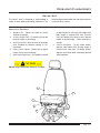
OPERATOR'S COMPARTMENT CONTROLS
The following pages provide information on the
controls in the operator's compartment. The design,
location, and mounting position of these controls
enable the operator to perform a variety of tasks
without moving from the driver's seat.
TURN SIGNAL LEVER/DIMMER SWITCH
The turn signal lever serves the dual purpose of
energizing the vehicle turn signals and changing the
vehicle headlights from one setting to the other.
To activate the turn signals, move lever downward for
a left-hand turn or upward for a right-hand turn. turn
signal lever automatically cancels after turn is
complete.
To switch headlights from the low beam setting to the
high beam setting, pull the turn signal lever upward
and release. To return vehicle headlights to the low
beam setting, pull turn signal lever upward again and
release.
Page 3.32
The vehicle's headlights have an optional high beam
flash provision. With the headlight switch in the ON or
OFF position, pull upward on the turn signal lever and
release to flash high beams.
OPERATOR'S COMPARTMENT
POWER STEERING
Power steering uses energy from your engine to
assist you in steering the vehicle. When the engine is
off, or if the power system becomes inoperative, the
vehicle can still be manually steered, but requires
increased driver effort.
Should you notice any change in effort required to
steer during normal vehicle operation, have the power
steering system checked. A hissing sound at full left or
full right steering wheel position is normal.
_______ NOTICE _______
After any severe impact such as striking large
potholes, inadvertent sliding into curbs on icy
roads, or a collision involving the front end,
observe the steering wheel alignment. If the
spokes of the wheel seem to be in a different
position while driving, have the front suspension
and steering checked for possible damage.
CAUTION
Never hold the steering wheel against the stops
(extreme right or left) for more than five seconds.
If you hold the wheel against the stops longer than
five seconds, the power steering pump could be
damaged.
TILT/TELESCOPING STEERING COLUMN
The tilt steering column enables the operator to adjust
the angle and height of the steering column to a more
comfortable driving position.
CAUTION
Do not adjust while vehicle is in motion.
To adjust the angle of the steering column, locate the
small lever underneath the turn signal lever. Pull lever
towards steering wheel and hold while tilting the
steering wheel at a comfortable position. Release
lever to lock column in position.
To adjust the height of the steering column, locate the
small lever underneath the turn signal lever. Push the
lever and hold while telescoping the steering wheel to
the desired position. Release lever to lock column in
position.
Page 3.33
SAF-T-LINER® EFX OPERATOR’S MANUAL
ELECTRONIC ACCELERATOR PEDAL
The accelerator pedal is an electric rheostat type
control that sends a gradually increased current to the
engine to control engine rpm and vehicle speed.
BRAKE PEDAL (HYDRAULIC)
The brake pedal controls the application of the vehicle
service brake. Downward pressure forces the
movement of hydraulic fluid from a booster or master
cylinder to each wheel. Anticipating the stop and using
light pressure will result in increased brake pad life.
BRAKE PEDAL (AIR)
The brake pedal controls the application of the vehicle
service brake. Downward pressure on the brake pedal
decreases the vehicle speed by applying air to the
brake chambers at each wheel and stops the vehicle
when desired by the operator. Anticipating the stop
and using light application of the brakes will result in
increased life of brake linings and drums. Continuous
heavy applications result in premature wear due to
excess heat.
CAUTION
Overheating the brakes may increase the distance
required to stop the vehicle.
Page 3.34
OPERATOR'S COMPARTMENT
SUN VISOR
Six inches x 30" plastic with finished edge mounted to
windshield header.
Never use an abrasive cleaner. Keep mounting
brackets tight.
Optional sun visor is available in three versions:
1. A plexiglass 6" x 30" with aluminum legs
mounted over the driver's window and/or over
the right side of windshield.
2. A 6" x 30" California sun visor, black, nontransparent, mounted in pivot brackets over the
driver's window.
3. A 6" x 30" visor mounted right side of windshield
in addition to standard left side visor.
Clean with plexiglass cleaner and a soft dry towel.
Horn Button
The electric horn alerts other motorists, pedestrians
and waiting passengers of vehicle presence. Push
down on center part of steering wheel to activate horn.
Release pressure to deactivate horn.
EMERGENCY FLASHERS
The emergency flashers enable the operator to alert
other motorists of the vehicle's position in the road.
Pulling the knob out activates the emergency flashers.
Pushing the knob in deactivates the emergency
flashers.
The emergency flashers should be activated when the
vehicle is disabled in the street and obstructing traffic,
stopping due to an emergency, in tow, or proceeding
at very reduced speed.
Page 3.35
SAF-T-LINER® EFX OPERATOR’S MANUAL
DEFROSTER FANS (OPTIONAL)
The defroster fans are used to help clear the
windshield and driver's window for better visibility. The
fans run at either low or high speed. The fans must be
cleaned and the fasteners tightened occasionally.
Doran Monitor, Exterior 4 or 8 Light (Optional)
The Doran exterior light monitoring system (4, 8, 12,
16) monitors the condition of those exterior vehicle
lights identified by the type of monitor board. The
monitor provides the operator with the location of any
malfunctioning light. In the event that a bulb has
become damaged or burned-out or the circuit is
interrupted, a corresponding light on the Doran panel
goes off. The Doran panel should be checked daily to
verify the operation of all warning lights.
Page 3.36
OPERATOR'S COMPARTMENT
DRIVER'S SEAT
The driver's seat is designed to accommodate a
variety of driver builds and seating preferences. The
following adjustments enable the seat to be moved for
maximum driver comfort:
MECHANICAL BASE SEAT
1.
2.
3.
4.
5.
Backrest Tilt - Rotate the knob for infinite
selection of settings.
Cushion Height Front - Lift handle, pull up and
forward. Choice of two settings.
Seat Fore-and Aft - Move the lever left and slide
seat. Provided for locked-in settings in 1/2"
increments.
Rear Cushion Adjuster - Rotate lever to adjust
height. Choice of three settings.
Seat Height Adjustment - Pull paddle rearward
6.
to adjust height. To raise seat, pull handle while
body weight is removed from seat. To lower
seat, pull handle while sitting in seat. Release
handle at desired height - infinite selection of
settings.
Lumbar Adjustment - To fully inflate lumbar,
depress valve button while all body weight is
removed from seat back. To deflate lumbar,
depress valve button while maintaining desired
seating position.
CAUTION
DO NOT adjust seat while vehicle is in motion.
6
1
4
5
2
3
Page 3.37
SAF-T-LINER® EFX OPERATOR’S MANUAL
AIR BASE SEAT
1.
2.
3.
4.
5.
Backrest Tilt - Rotate knob for infinite selection
of settings.
Cushion Height Front - Lift handle, pull up and
forward. Choice of two settings.
Seat Fore-and-Aft - Move lever left and slide
seat. Provided for locked-in settings in 1/2"
increments.
Rear Cushion Adjuster - Rotate lever to adjust
height. Choice of three settings.
Seat Height Adjustment - Push rocker up to
inflate. Push rocker down to deflate. Infinite
height and weight selection.
6.
7.
8.
9.
Lumbar Adjustment - Push rocker up to inflate
lumbar. Push rocker down to deflate lumbar.
Optional Triple Chamber Air Lumbar - Lower,
middle and upper chambers individually
adjustable.
Optional Air Bolsters - Cushion and back
individually adjustable.
Optional Height Adjuster with Memory - Rotate
lever to select desired ride height - infinite
selection.
CAUTION
DO NOT adjust seat while vehicle is in motion.
1
4
8
7
3
6
2
Page 3.38
5
9
OPERATOR'S COMPARTMENT
DRIVER'S SEAT, WITH BOX PEDESTAL
1.
2.
3.
Backrest Tilt - Rotate the knob for infinite
selection of settings.
Cushion Height Front - Lift handle, pull up and
forward. Choice of two settings.
Seat Fore-and Aft - Move the lever left and slide
seat. Provided for locked-in settings in 1/2"
increments.
4.
Seat Height Adjustment - Rotate the four (4)
knobs on the box pedestal (two on each side) to
loosen and select slot for desired height.
Tighten knobs to secure in position.
CAUTION
DO NOT adjust seat while vehicle is in motion.
1
4
2
3
Page 3.39
SAF-T-LINER® EFX OPERATOR’S MANUAL
DRIVER'S SEAT BELT
The driver's seat belt should be worn at all times when
operating the vehicle.
Application - Hold buckle in one hand and pull
connector belt across pelvic region (hip bone).
Prior to adjusting or fastening the seat belt, adjust the
seat to a comfortable driving position. Refer to the
Driver's Seat part of this section for adjustment
information.
Make sure neither belt is twisted. Insert connector belt
into open end of buckle. A "snap" sound indicates the
connector belt is properly engaged with the buckle.
However, tug on the belt to ensure that the connector
belt is properly engaged with the buckle. The belt
retractor automatically eliminates belt slack for a snug
but comfortable fit.
The driver's seat belt has a wall mounted retractor
with a single belt that runs through a bracket located
over the window and back down to the driver's seat.
The buckle should slide freely on the belt as the driver
pulls the belt across his body to the push button latch
on the door side of the seat.
A shoulder adjustment strap is incorporated into the
belt. It consists of a sleeve that slides on the belt close
to the overhead bracket. (See illustration.) The sleeve
is connected to a loop that limits the movement of the
seat belt as it crosses the driver's shoulder.
(CONTINUED
Page 3.40
ON NEXT PAGE.)
OPERATOR'S COMPARTMENT
DRIVER'S SEAT BELT (CONTINUED)
Release - The seat belts contain a push button
located on the buckle. To release the belt push in on
the button and the latch will disconnect from the
buckle.
CAUTION
The driver must always wear a seat belt when
operating the vehicle.
Inspection - Inspect the seat belts and tether belts as
follows.
1. Check the web for fraying, cuts, or extreme wear,
especially near the buckle latch plate and in the
D-loop guide area.
2. Check the web for extreme dirt or dust, and for
severe fading from exposure to sunlight.
3. Check the buckle and latch for operation and for
wear or damage.
4. Check buckle cable for damage, sharp bends,
kinks, frayed or exposed strands, and loose or
corroded fasteners.
5. Check the Komfort Latch for function and cracks
or other damage.
6. Check the web retractor for function and
damage.
7. Check the mounting bolts for tightness and
tighten any that are loose.
Page 3.41
SAF-T-LINER® EFX OPERATOR’S MANUAL
ENGINE ACCESS DOORS
UPPER ACCESS
DOOR
LOWER ACCESS DOOR
FOR EASE
OF CHECKING ENGINE OIL LEVEL,
TRANSMISSION FLUID LEVEL, AND
POWER STEERING FLUID
RESERVOIR.
Page 3.42
OPERATING THE VEHICLE
This section provides the operator with important
operational information. The following pages contain
helpful driving tips, information for daily operation, and
procedures for operation in emergency or inclement
weather conditions.
understanding of component location, function, and
operation is important to the safe operation of the
vehicle and the protection of all passengers.
It is important to carefully read and understand the
following pages before operating the vehicle. A proper
DAILY CHECKLIST
The vehicle should be inspected daily (prior to
operation) to ensure safe operation and reliable
service. The following is a minimum daily checklist.
Additional checklist items may be added according to
local operating conditions. Any items that fail to meet
the checklist should be reported immediately to the
maintenance supervisor and repaired, as necessary,
before placing vehicle in service.
EXTERIOR CHECKLIST
•
•
•
•
Clean windshield, driver's window, door glass,
mirrors, and headlights.
Inspect vehicle exterior. Make sure all vehicle
identification is clear, clean, and operates
properly. Verify that all under-vehicle
compartments are secure.
Inspect tires for sidewall or tread damage,
excessive or uneven tread wear and proper
inflation. Inspect wheels and rims for cracks,
etc. Check lug nuts for tightness.
Drain moisture from air reservoir tanks. Check
for oil, fuel, coolant, and power steering fluid
leaks.
•
•
•
Unplug block heater and oil heater, if so
equipped.
Inspect steering mechanism for proper
operation.
Inspect for any damage to the After-Treatment
Device and the Mitigation Device.
Page 4.1
SAF-T-LINER® EFX OPERATOR’S MANUAL
ENGINE COMPARTMENT SERVICE
CAUTION
Do not service the engine until the transmission
gear shift selector lever is in "N" (Neutral) and the
parking brake is engaged.
Unless the particular procedure requires you to
run the engine while working in the engine
compartment, you should always turn off the
ignition and remove the key, avoiding the
possibility of personal injury.
Avoid touching fan blades with hands.
ENGINE COMPARTMENT CHECKLIST
Make sure the vehicle engine is off and parking
brake is engaged before performing the following
tasks.
•
•
•
Check coolant level (only with engine cool). As
necessary, fill with a 50/50 water/antifreeze
solution. Fill to the cold max line; do not over
fill.
•
You may lock some emergency roof hatches in
a partly open position for fresh air. Do not leave
them open as a regular practice. Keep in mind
the bus' higher clearance while driving with them
open.
Check engine oil level before starting and when
refueling.
Check belt for cracks, breaks, frayed edges, and
proper tension.
INTERIOR CHECKLIST
People sometimes damage unattended buses.
•
•
•
•
Aisles and stepwells must always be clear of
objects.
Emergency exit handles must be in safe working
condition.
Check all emergency exits for proper operation.
The "Emergency Exit" sign on an emergency
door must be clearly visible.
Page 4.2
OPERATING THE VEHICLE
FINAL CHECK
•
•
•
•
Adjust driver's seat and steering wheel.
Start engine; look and listen for signs of trouble.
Check all gauges and warning lights.
Check and adjust mirrors. Adjust the vehicle
mirrors according to the following procedures
before vehicle begins daily service:
•
Crossview Mirrors - Swivel the mirror head to give a
clear view of area directly in front of the vehicle.
•
•
•
Verify parking brake is applied and check
operation of doors, emergency escape hatches
and emergency exits.
Check operation of interior lights and stepwell
lights.
Visually inspect vehicle, while engine is running,
for fluid or exhaust leaks.
Check operation of all exterior lights, safety
equipment and signal devices.
Interior Rearview Mirrors - Adjust mirror to provide a
clear view of passenger area and roadway.
Convex Mirrors (Optional) - These mirrors provide a
wider view of the adjacent lane. However, cars and
other objects will appear smaller and further away
than when viewed from a flat mirror. Use care when
judging distances with this type of mirror.
BEFORE DRIVING OFF
•
•
•
•
•
Secure all doors.
Check operation of defroster and heater
blowers, windshield wipers/washers and horn.
Fasten seat belt.
Check air pressure gauges for maximum
pressure.
Check operation of service brake and parking
brake.
•
Visually check all gauges for normal operation
readings.
Page 4.3
SAF-T-LINER® EFX OPERATOR’S MANUAL
NORMAL STARTING
It is important that the vehicle operator be familiar
with all operating controls and indicators before
attempting to operate the vehicle.
3. Turn ignition key ON.
4. Wait until the Instrument Cluster performs selfcheck, then start.
The following must apply before starting the vehicle:
• All vandalocks, if applicable, must be in
"unlatched position".
If engine fails to start within 30 seconds, wait 1 to
2 minutes and repeat step 4.
To start the vehicle, use the following procedure:
1. Apply parking brake if not already applied.
2. Place transmission shift control in neutral (N) /
Park.
COLD WEATHER STARTING
To start the vehicle during cold weather, use the
following procedure:
1. Apply parking brake if not already applied.
2. Place transmission shift control in neutral (N) /
Park.
IMPORTANT: Do not depress accelerator
during step 3.
3. Turn ignition key to ON. Wait until the Instrument
Cluster performs self-check, then start.
4. On units equipped with a master control switch,
turn switch to DAY and press engine start
button.
Page 4.4
When engine starts, reduce engine speed to fast idle
rpm. Do not apply load or increase engine speed until
oil pressure gauge indicates normal (approximately
15 seconds).
_______ NOTICE _______
After starting a turbocharged engine, do not
accelerate engine above 1000 rpm until oil
pressure gauge indicates normal.
OPERATING THE VEHICLE
BLOCK HEATERS
Block heaters are heating elements installed in the
engine water jacket to aid in cold starting by keeping
the engine coolant warm while the engine is not
operating. The heater should be plugged in anytime
the ambient temperature is expected to be 40oF (4oC)
or below. The heater must be connected to an
external source of electrical current. Heaters are
available for 120 AC and possess a 750 watt capacity.
An optional weather proof plug-in receptacle is
mounted in the exterior panel above the front bumper.
Make sure that cover stays closed to prevent damage
to connection.
ENGINE WARM-UP
After the engine starts, time is needed for an oil film to
re-establish between moving parts. Operate the
engine at low load until all systems reach normal
operating temperature. Observe all gauges during
warm-up period to verify that vehicle is ready to enter
service.
Page 4.5
SAF-T-LINER® EFX OPERATOR’S MANUAL
ENGINE IDLING/FAST IDLE SYSTEM
Idling the vehicle's diesel engine in cold temperatures
will not result in desired engine temperature. Actually,
a diesel engine cools down when left idling. The
vehicle operator should activate the fast idle feature.
The vehicle operator should activate the fast idle
switch to automatically increase engine idle speed to
950 rpm. This higher idle speed aids vehicle warm-up
and air pressure build-up.
CAUTION
Avoid extended or unnecessary idling. Extended
idling of the engine (ten minutes or more),
particularly at "high" engine speeds could
produce excessive system temperatures that
could damage your vehicle.
MAIN CIRCUIT BREAKER
The main body and chassis power supply cables are
circuit protected by a Mega Fuse Junction Block
(MFJB). The MFJB and main power disconnect switch
are housed in a NEMA enclosure for protection from
the environment and debris. The NEMA enclosure is
mounted to the side of the battery box through which
the main power disconnect switch is accessible. The
main starter / alternator cable branches from inside
this enclosure, keeping its terminals protected from
the environment.
MEGA FUSE JUNCTION BLOCK
Page 4.6
OPERATING THE VEHICLE
DRIVING TIPS (AUTOMATIC TRANSMISSIONS)
The vehicle operator should use care when
accelerating or downshifting on slippery road
surfaces. Sudden acceleration or engine braking,
caused by shifting to a lower gear range, can result in
a loss of vehicle control. This is very important on
snow or ice covered roads.
CAUTION
Do not coast the vehicle in neutral. Severe
transmission damage may result and vehicle will
not have benefits of engine braking.
If the vehicle is stuck in sand or mud, do not attempt
to pull the bus out under its own power; it will only mire
itself deeper. Request professional towing assistance.
ROCKING THE VEHICLE
CAUTION
"Rocking" the vehicle is moving it forward and
backwards in a steady rhythm. If the vehicle is
stuck, have it pulled out. Do not attempt to "rock"
the vehicle.
If rocking the vehicle is necessary, even at low
speeds, it may cause engine overheating, axle
damage, transmission damage or failure, or tire
damage.
SPECIAL DRIVING INSTRUCTIONS
WARNING
Warning: To reduce the risk of personal injury,
before going down a steep or long grade, reduce
speed and down shift the transmission. Do not
hold the brake pedal down too long or too often
while going down a steep or long grade. This
could cause the brakes to overheat, reducing their
effectiveness. As a result, the vehicle will not slow
down at the usual rate. Failure to take these steps
could result in the loss of vehicle control.
To avoid skidding on slippery roads, do not down
shift into "1" (Low) at speeds above 20 mph (32
kph).
On slippery surfaces, avoid quick movements of
steering wheel. Decrease your speed and allow for
extra stopping distance required by these
conditions. Apply the brakes by pumping the
pedal steadily and evenly to avoid wheel lock-up
and loss of vehicle control.
Avoid driving through flooded areas unless you
are sure the water is no higher than the bottom of
the wheel rims. Drive through slowly. Allow
adequate stopping distance since wet brakes do
not grip well. After driving through water, gently
apply the brakes several times while the vehicle is
moving slowly to dry the brakes.
When driving on icy or gravelled surfaces, reduce
speed. Avoid sharp turning maneuvers.
Page 4.7
SAF-T-LINER® EFX OPERATOR’S MANUAL
PARKING
When parking the vehicle, use the following
sequence:
within the chamber, allowing the spring to set the
brakes.
1. Shift transmission lever to “Neutral” or “Park”
with engine running. With Push Button, select
the “Neutral” position while engine is running.
2. Apply parking brake. Let unit idle approximately
five minutes.
3. Shut off engine.
4. Place chock blocks under at least one wheel.
In the event the air system is below 60 psi, the parking
brakes cannot be released until the air system is
recharged either by the running engine to charge the
system with the engine-driven air compressor or by
charging system from an external source, such as a
shop air supply. If this is not possible, the spring
(parking) brakes must be released manually before
moving the bus. Refer to “Release Parking Brake Manually” below.
Air Brake: The parking brakes are mechanically
applied via the action of a heavy coil spring against
the service brake push rod assembly on the rear axle
brakes only.
Refer to the Operator’s Compartment section of this
manual for information concerning the Hydraulic
Brake.
Air pressure within the spring brakes chamber holds
the parking brake in the released position. Pulling the
parking brake control valve out releases the pressure
RELEASE PARKING BRAKE - MANUALLY
The following procedure is provided for manually
releasing the parking brake.
WARNING
Block the wheels before beginning this
procedure. The vehicle will roll when the parking
brake is manually released.
Determine the type of brake chamber on the vehicle.
Certain types have release rods that are permanently
installed in the rear of the chamber housing. Others
have the rod stored on the side of the chamber
housing.
Page 4.8
For either application, make sure rod is installed in
center of brake chamber. Turn rod 1/4 turn clockwise
and install nut on rod. Turn nut clockwise on either
chamber to "cage" or release the spring parking
brake.
OPERATING THE VEHICLE
BATTERY CARE (MAINTENANCE FREE BATTERY)
WARNING
Batteries release explosive gas as a by-product of
their chemical activity. Do not smoke when
working around batteries. Put out all flames and
remove any source of sparks or intense heat.
Make sure the battery compartment is completely
vented before disconnecting or connecting
battery cables.
Battery acid is extremely harmful if splashed in
the eyes or on the skin. Always wear a face shield
and protective clothing when working around
batteries.
Damaged, chafed, or kinked wiring can cause
electrical short-circuits and lead to fires, causing
property damage, injury, or death. Clean, inspect,
and maintain wiring and connections carefully.
1.
1.1 Clean and tighten the battery ground cable,
terminal, and clamps.
1.2 Inspect the retainer assembly (or battery holddowns) and the battery box. Replace worn or
damaged parts. Remove any corrosion with a
wire brush, and wash with a weak solution of
baking soda and water. Rinse with clean water,
the dry. Paint the retainer assembly, if needed,
to prevent rusting.
1.3 Check that foreign objects, such as stones,
bolts, and nuts, are removed from the battery
box.
1.4 After cleaning, connect the cables to the
batteries, and tighten them to the torque
specifications listed on the battery, generally 10
to 15 lbf-ft (14 to 20 N-m).
1.5 Coat the battery terminals with dielectric
grease.
Inspect the battery cables for wear, and replace
as needed. Clean the cable connector
terminals with a wire brush:
Page 4.9
SAF-T-LINER® EFX OPERATOR’S MANUAL
Emergency Starting With Jumper Cables
When using jumper cables, follow the instructions
below.
WARNING
Batteries release explosive gas. Do not smoke
when working around batteries. Put out all flames
and remove all sources of sparks or intense heat
in the vicinity of the battery. Do not allow the
vehicles to touch each other. Do not lean over the
batteries when making connections, and keep all
other persons away from the batteries. Failure to
follow these precautions could lead to severe
personal injury as a result of an explosion or acid
burns.
_______ NOTICE _______
Make sure that both starting systems are the same
voltage. Electronic devices on both vehicles can
be damaged when connected to a vehicle with a
different operating voltage.
1. Apply the parking brakes and turn off all lights
and other electrical devices.
IMPORTANT: Do not attempt to jump start a
damaged battery.
2. Open the battery door (location will vary) to
access the batteries. Slide the battery tray out.
3. Connect the positive (+) jumper cable to the
positive terminal on the discharged battery. See
Jumper Connections diagram on next page.
4. Connect the other end of the positive jumper
cable to the positive terminal on the booster
battery providing the charge.
WARNING
Do the next step exactly as instructed and do not
allow the clamps of one cable to touch the clamps
of the other cable. Otherwise, a spark could occur
near a battery, possibly resulting in severe
personal injury from explosion or acid burns.
5. Connect the negative (-) jumper cable to the
negative terminal on the booster battery.
6. Connect the other end of the negative jumper
cable to the negative ground stud on the vehicle
requiring the jump start.
7. Start the engine of the vehicle providing the
jump start and let the engine run for a few
minutes to charge the batteries of the other
vehicle.
_______ NOTICE _______
Do not crank the engine for more than 30 seconds
at a time during any of the following procedures.
Wait two minutes after each try to allow the starter
to cool. Failure to do so could cause starter
damage.
_______ NOTICE _______
Always connect the batteries and jumper cables
correctly (positive-to-positive and negative-tonegative). Connecting a charging device
backwards (positive-to-negative) can severely
damage the vehicle electrical content and cause
non- warrantable failures.
Page 4.10
(Continued on next page.)
OPERATING THE VEHICLE
4
B
E
D
3
2
1
A
DISCONNECT
A.
B.
C.
1.
2.
3.
4.
JUMPER CABLES IN THE
C
REVERSE
ORDER THAT THEY WERE CONNECTED.
DISCHARGED BATTERY
D. NEGATIVE JUMPER CABLE
NEGATIVE GROUND
E. BOOSTER BATTERY
POSITIVE JUMPER CABLE
1ST CONNECTION: POSITIVE JUMPER CABLE TO DISCHARGED BATTERY
2ND CONNECTION: POSITIVE JUMPER CABLE TO BOOSTER BATTERY
3RD CONNECTION: NEGATIVE JUMPER CABLE TO BOOSTER BATTERY
4TH CONNECTION: NEGATIVE JUMPER CABLE TO NEGATIVE GROUND STUD (DISCHARGED BATTERY)
8. Attempt to start the engine of the vehicle with
the batteries receiving the charge.
9. When the engine starts, let it idle for a few
minutes.
WARNING
Do the next step exactly as instructed and do not
allow the clamps of one cable to touch the clamps
of the other cable. Otherwise, a spark could occur
near a battery, possibly resulting in severe
personal injury from explosion or acid burns.
10. Disconnect the negative jumper cable from the
negative cable stud on the jump started vehicle.
11. Disconnect the negative jumper cable from the
booster battery.
12. Disconnect the positive cable from the booster
battery.
13. Disconnect the other end of the positive jumper
cable from the jump started vehicle.
14. Slide the battery tray back into position and
close the battery door.
Page 4.11
SAF-T-LINER® EFX OPERATOR’S MANUAL
BATTERY REPLACEMENT
CAUTION
Wiring batteries backwards can cause serious
damage to the electrical system.
WARNING
Battery posts, terminals, and related accessories
contain lead and lead compounds, chemicals
known to the State of California to cause cancer
and reproductive harm. Wash hands after
handling.
Page 4.12
OPERATING THE VEHICLE
TIRE INFLATION PRESSURE
CAUTION
Over or underinflated tires can affect vehicle
handling. Pressure can fall suddenly, resulting in
loss of vehicle control.
Do not drive over posted speed limits or at
excessive speeds. This vehicle is not equipped
with high speed capability tires and should never
be operated in excess of 74 mph (119 kph) for
even a short time. Doing so can result in tire
failure, loss of control and possible injury.
IF YOU GET A FLAT TIRE
WARNING
To minimize the risk of personal injury, do not put
any portion of your body under the vehicle while
the vehicle is on the jack. A jack is for emergency
wheel and tire changing only. If you wish to
service the vehicle, use jack stands. Never start
the engine while the vehicle is on the jack.
When a wheel is changed, or any time the wheel
lug nuts have been loosened, the lug nuts should
be properly torqued. (Refer to the Maintenance
Section for proper torque value.) Retighten at 100
miles (160 km) and at 500 miles (800 km).
To prevent inadvertent vehicle movement while
changing a tire, always block the wheels
diagonally opposite the wheel being changed. Be
sure the park brake is engaged.
Do not raise the vehicle using a bumper jack.
Bumper components can be damaged and the
bumper jack can slip, resulting in personal injury.
Make sure the jack is on a solid surface. Brace up
the vehicle with jack stands, or equivalent, at
jacking points so that the jack cannot fail.
Page 4.13
SAF-T-LINER® EFX OPERATOR’S MANUAL
CHASSIS JACKING POINTS
CAUTION
Do not raise vehicle using a bumper jack. Use
only jack (or equivalent) supplied by vehicle
manufacturer with your vehicle. Position jack only
at prescribed jacking points.
If you must raise the vehicle for servicing, use
adequate jack stands. Never service a vehicle
while it is supported only by a jack.
To prevent inadvertent vehicle movement while
changing a tire, always block the wheel diagonally
opposite the wheel being changed. Be sure the
park brake is engaged.
Do not put any portion of your body under the
vehicle while vehicle is supported by a jack. Never
start engine while vehicle is supported by a jack.
AIR RIDE JACKING POINT
On units equipped with rear air suspension, one
should use a minimum of a 4" x 4" block of wood or
steel on top of the jack and locate the jack beneath the
beam directly below axle housing.
To prevent inadvertent movement while jacking the
vehicle, always block the wheel diagonally opposite
the wheel being raised. Be sure the park brake is
engaged.
Page 4.14
OPERATING THE VEHICLE
VEHICLE TOWING AND CONNECTING INSTRUCTIONS
Towing rules and regulations vary from federal, state,
local, and transit authority. These laws must be
followed when towing the vehicle.
Proper equipment must be used to prevent damage to
vehicles during the towing procedure. Use a safety
chain that is completely independent of the primary
towing attachment.
Climatic conditions, road conditions, equipment,
wrecker operator experience, etc., will dictate towing
speed; however, it should never exceed 45 mph.
Connect the towing equipment to the main structural
parts of the vehicle chassis. The chain should be
hooked around the front axle outboard of the springs.
Do not attach to bumpers, tow hooks, or brackets.
Use only equipment designed for this purpose,
following directions of the wrecker manufacturer.
CAUTION
Thomas Built Buses recommends that when an
EFX requires towing, that it be towed from the
front whenever possible.
If the need arises for the unit to be towed from the
rear, the towing operator should make sure the
steer axle tires are rated high enough to support
the unit weight when towing from the rear. It is
also recommended that when towing from the rear
the distance towed is less than 30 miles at 45 mph.
TOWING
CAUTION
Block the disabled vehicle's wheels with chock
blocks before preparing it for towing. Failure to do
so will result in a hazardous condition where the
vehicle could roll uncontrollably.
Either removal of the driveshaft or removal of the
axle shafts are acceptable procedures prior to
towing.
Do not use the two tow hooks under the front of
the vehicle to lift it off the ground. The tow hooks
are designed to tow the vehicle with all of its
wheels on the ground.
CAUTION
Thomas Built Buses recommends that when an
EFX requires towing, that it be towed from the
front whenever possible.
If the need arises for the unit to be towed from the
rear, the towing operator should make sure the
steer axle tires are rated high enough to support
the unit weight when towing from the rear. It is
also recommended that when towing from the rear
the distance towed is less than 30 miles at 45 mph.
Page 4.15
SAF-T-LINER® EFX OPERATOR’S MANUAL
FRONT END TOWING - ALL WHEELS ON GROUND
This is the preferred way of towing. The vehicle may
be towed on all wheels provided the steering is
operating normally. Remember that the power
steering will not have power assist, and the air brakes
are disabled. There must be an appropriate tow bar
installed between the towing vehicle and the disabled
vehicle.
To prepare a disabled vehicle for front end towing with
all wheels on the ground, the following steps are
necessary:
1. Block the Wheels of the disabled vehicle.
2. Release the emergency brake system by
compressing the brake chamber springs as
outlined under Release Parking Brake Manually.
_______ NOTICE _______
This is to prevent the possibility of the emergency
brake being applied during towing.
3. Remove the drive shaft from the unit.
Care should be taken to ensure the U-Joint bearings
are not lost.
Page 4.16
_______ NOTICE _______
If the unit is to be towed more than 10 miles the
rear axle shafts should be removed instead of the
drive shaft.
4. If axle shafts are removed, cover the hub
openings to prevent the loss of lubricant or entry
of dirt or foreign objects.
OPERATING THE VEHICLE
FRONT END TOWING - FRONT WHEELS OFF GROUND
Proper equipment must be used to prevent damage to
the vehicle during the towing procedure. Connect the
towing equipment to the main structural parts of the
vehicle chassis. The chain should be hooked around
the front axle outboard of the springs. DO NOT attach
to bumpers, tow hooks, or brackets. Use only
equipment designed for this purpose following
directions of the wrecker manufacturer. A safety chair
that is completely independent of the primary towing
attachment must be used.
To prepare a disabled vehicle for front end towing with
the front wheels off the ground, the following steps are
necessary:
1. Block the wheels of the disabled vehicle.
2. Release the emergency brake system by
compressing the brake chamber springs as
outlined earlier in this section, entitled Release
Parking Brake - Manually.
_______ NOTICE _______
This is to prevent the possibility of the emergency
brake being applied during towing.
3. Remove the drive shaft from the unit.
Care should be taken to ensure the U-Joint bearings
are not lost.
_______ NOTICE _______
If the unit is to be towed more than 10 miles the
rear axle shafts should be removed instead of the
drive shaft.
4. If axle shafts are removed, cover the hub
openings to prevent the loss of lubricant or entry
of dirt or foreign objects.
SPECIAL TOWING INSTRUCTIONS
1. All federal, state, and local laws regarding such
items as warning signals, night illumination
speed, etc., must be followed.
2. Safety chains must be used.
3. No vehicle should ever be towed over 45 mph
(70 kph).
4. Loose or protruding parts of the damaged
vehicle should be secured prior to moving.
5. A safety chain system completely independent
of the primary lifting and towing attachment must
be used.
6. Operators should refrain from going under a
vehicle which is being lifted by the towing
equipment unless the vehicle is adequately
supported by safety stands.
7. No towing operation which for any reason
jeopardizes the safety of the wrecker operator,
other motorists or bystanders should be
attempted.
Page 4.17
SAF-T-LINER® EFX OPERATOR’S MANUAL
AFTER TOWING
After towing the vehicle, block the rear wheels,
Remove the covers from the hub openings and install
the axle shafts. Apply the emergency brake system
DIESEL FUEL SPECIFICATIONS - CUMMINS
Use only Ultra Low Sulfur Diesel (ULSD) fuel.
ULSD is required for correct operation of the
After-Treatment system, otherwise the engine may
not meet emission regulations and may damage
the After-Treatment System. ULSD contains
15ppm sulphur.
Refer to the Cummins Owners Manual for more
information on this subject.
FUEL TANK FILLING
CAUTION
Handle fuel with care; it is highly flammable. Do
not refuel the vehicle while smoking or when near
open flames or sparks.
Always stop engine before refueling vehicle.
Fill fuel tank outdoors.
Prevent fires by keeping vehicle clean of
accumulated trash, grease and other debris.
Always clean up spilled fuel.
If fuel is observed overflowing from cap, remove
cap with caution. Internal pressure may cause fuel
expulsion.
Page 4.18
before disconnecting the towing vehicle. Check and fill
rear axle with oil as described in the lubrication chart.
OPERATING THE VEHICLE
WATER IN FUEL
During refueling, it is possible for water and other
contaminants to be pumped into your fuel tank along
with fuel. Fuel that is contaminated by water or dirt can
cause severe damage to engine.
Drain water from separator until clear fuel is observed.
INSPECTING FOR ROAD DAMAGE
The suspension and steering linkage in your vehicle
should be inspected periodically for abnormal
looseness and damaged seals. Also be alert for any
changes in steering action. Hard steering, excessive
free play or unusual sounds when turning or parking
indicate a need for inspection or servicing.
Periodically, check for broken springs or shock
absorber mounts.
_______ NOTICE _______
After any severe impact such as striking large
potholes, inadvertent sliding into curbs on icy
roads, or a collision involving the front end,
observe the steering wheel alignment. If the
steering wheel spokes seem to be in a different
position while going down the road, have the front
suspension and steering checked for possible
damage.
Page 4.19
SAF-T-LINER® EFX OPERATOR’S MANUAL
EXTENDED VEHICLE STORAGE
Any time vehicle will be out of use over an extended
period of time (60 days or more), the following steps
should be taken to give it maximum protection:
1. Change engine oil. Used oil does not give
adequate protection.
2. Service air cleaner.
3. Cooling system was initially protected with
antifreeze to -34oF (-1oC). If colder
temperatures are expected, adjust antifreeze
mixture. If coolant has been in vehicle for 36
months or 30,000 miles (48,000km), flush
cooling system. Fill system with mixture of
antifreeze and softened water, and be sure
coolant contains a rust inhibitor. Do not use
additional rust inhibitors or anti-rust products, as
they may not be compatible with a radiator
coolant that already contains rust inhibitors.
4. Remove and clean battery. Store in a cool, dry
place, and keep it charged.
5. Cover dash with opaque material.
Page 4.20
6. Check and maintain recommended tire
pressure. Protect tires from heat and sunlight.
7. Thoroughly clean vehicle. Touch up any painted
surfaces that are scratched or chipped.
8. Lubricate all grease fittings.
9. Add a commercially available fuel stabilizer to
the fuel tank, following manufacturer's
instructions, then idle the engine long enough to
ensure complete circulation of the fuel stabilizer
throughout the fuel system.
OPERATING THE VEHICLE
INITIATING A STATIONARY (PARKED) REGENERATION (REGEN)
CAUTION
Before attempting to initiate a Stationary Regen,
be sure to turn off Fast Idle Switch.
3. This method uses the Cummins Software Tool,
INSITE™ version 6.52 or later to initiate a
Stationary Regen:
Interface to the nine-pin diagnostic connector,
located under the left side of the dash to the PC.
Open INSITE™ and go to the After-Treatment
section. Follow the software instructions to
complete the Regen.
There are three possible methods of initiating a
Stationary Regen:
1. DPF Regen Switch located on the dash: For the
switch to activate stationary regeneration the
following parameters must be met.
1.1 start engine and let idle
1.2 the transmission must be in Neutral
1.3 the parking brake must be set
1.4 vehicle speed must be 0
1.5 regeneration must be required
1.6 the switch must be held down for 4 seconds.
2. Omit Exhaust System Regen Switch (service
connector) located near the 9-pin diagnostic
connector under the left side of dash: In order to
initiate a regen with service connector, the
following parameters must be met.
2.1 start engine and let idle
2.2 unplug the two-piece service connector
2.3 the transmission must be in Neutral
2.4 the parking brake must be set
2.5 vehicle speed must be 0
The engine will begin Stationary Regen. When
regen is complete, be sure to plug connector
back together.
For Stationary Regen following parameters must
be met.
3.1
3.2
3.3
3.4
start engine and let idle
the transmission must be in Neutral
the parking brake must be set
vehicle speed must be 0
When in Stationary Regen, engine speed will be
elevated to approximately 1200 rpms. After regen is
complete, the engine idle will return back to normal.
The DPF lamp and the HEST lamp turn off and the
bus is returned to service.
Page 4.21
SAF-T-LINER® EFX OPERATOR’S MANUAL
REMOTE MANUAL AIR TANK DRAIN VALVES (OPTIONAL)
Manual Drain valves allows the driver to drain the air
tanks without reaching under the unit. The access
door is located left side of the unit behind the battery
box.
OPEN
CLOSE
WET
Page 4.22
PRIMARY
SECONDARY
ACCESSORY
SPECIAL
EMERGENCY EQUIPMENT
This section provides the operator with important
information about the vehicle's emergency equipment.
Safety equipment on the Thomas vehicle varies
according to local, state, Federal, and operator
requirements.
It is important to carefully read and understand the
following pages before operating the vehicle. A proper
understanding of component location, function and
operation is important to the competent operation of
the vehicle and the protection of all passengers.
EMERGENCY DOOR
An emergency exit door is located at the rear of the
vehicle. Most doors have a locking capability in the
open position to allow a clear exit from the vehicle.
The opening hardware for the emergency exit door is
protected to prevent accidental opening. Instructions
for opening the emergency exit door are clearly
displayed on the door face.
_______ NOTICE _______
The vehicle should not be driven if an emergency
exit buzzer is sounding.
Opening of the emergency exit activates a warning
buzzer in the operator's compartment.
Page 5.1
SAF-T-LINER® EFX OPERATOR’S MANUAL
EMERGENCY WINDOW EXITS
The vehicle's emergency push-out windows also
function as emergency exits. To open the windows in
emergency situations, follow the instructions that are
clearly displayed on the window frame.
_______ NOTICE _______
The vehicle should not be driven if an emergency
exit buzzer is sounding.
_______ NOTICE _______
Some states require that operating instructions be
located on glass.
Page 5.2
EMERGENCY EQUIPMENT
EMERGENCY ROOF ESCAPE HATCH (OPTIONAL)
The vehicle may contain an emergency roof escape
hatch. The location of the hatch is subject to vehicle
build specifications according to Federal or State
Regulations variations. On vehicles equipped with an
emergency roof escape hatch, the opening
instructions are clearly displayed on the hatch cover.
FIRST AID KIT (OPTIONAL)
It is important that a first aid kit is maintained with the
vehicle. If items or components are used, they should
be replaced immediately. A need cannot be predicted;
thus, be prepared at all times.
BODY FLUID CLEAN-UP KIT (OPTIONAL)
The body fluid clean-up kit is used when any type of
body fluid comes in contact with the bus. It is
important that this kit be maintained with the vehicle at
all times. If items are used, they should be replaced
immediately.
Page 5.3
SAF-T-LINER® EFX OPERATOR’S MANUAL
SEAT BELT CUTTER (OPTIONAL)
Seat belt cutting knife used for the purpose of cutting
seat belt and wheelchair securement belts in
emergency situations. Located with other safety
equipment.
FIRE EXTINGUISHER (OPTIONAL)
The fire extinguisher should be inspected monthly to
verify that it contains sufficient charge. Observe gauge
on fire extinguisher for current condition. Recharge
fire extinguisher as necessary.
The chemical content of the fire extinguisher can be
corrosive to any metal it contacts. Excess chemical
from the fire extinguisher must be brushed or
vacuumed off. Washing the chemical off will cause a
severe corrosion problem.
TRIANGLES (OPTIONAL)
Three reflectorized triangles complete with carrying
case. Triangle unfolds and locks firmly in place.
Standard mounting location left side floor under first
seat.
Page 5.4
EMERGENCY EQUIPMENT
FUSEES (FLARES) (OPTIONAL)
Three 30 minute fusees in a cylindrical container
mounted with easy access by the driver. Operator
should be familiar with the proper use of the fusees.
FIRE AXES (OPTIONAL)
Fire axes are maintained with the bus for use in case
of emergency. Usually located in driver's area or
safety equipment compartment.
WRECKING BAR (OPTIONAL)
Wrecking bar is maintained with the bus for use in
case of emergency. Usually located in driver's area or
safety equipment compartment.
Page 5.5
SAF-T-LINER® EFX OPERATOR’S MANUAL
SAFETY EQUIPMENT BOXES AND ACCESSORY COMPARTMENT
Located over windshield with glass lettered
"Emergency Equipment Inside". May be equipped
with lock and buzzer, if so desired. Hinge must be
lubricated occasionally.
MAINTENANCE PROCEDURE - HEHR (HEHR OFFERED AS OPTION)
1. Open the window to its maximum position (as
determined by the props) so that the sides and
bottom of the inner window frame are visible and
accessible.
2. With a stiff fiber brush (do not use a wire brush)
and/or an air hose, remove any dirt or debris
from the latch area channels across the bottom
of the window and back frame.
3. Spray (or otherwise apply) a solvent cleaner
with dissolved oil (like WD-40), on the latch
parts on the bottom of the window and back
frame.
4. Cycle the latch mechanism a couple of times
with the inside and outside handles to allow the
lubricant to work-in.
5. Wipe down the latch area and back frame with a
cloth to remove excess oil and liquid.
Page 5.6
6. With the same cloth, wipe the seals on the sides
and across the bottom of the window and
around the seal contact area of the back frame
so that dirt is removed and a light oil film is left
on the metal and seals. (Silicone spray or
graphite spray may also be used. WD-40 or
silicone spray will provide better corrosion and
seal protection).
7. Close and open the window to verify latch
operation and force. When done, close the
window.
EMERGENCY EQUIPMENT
MAINTENANCE INTERVALS - HEHR (HEHR OFFERED AS OPTION)
If the vehicle is in daily use, Hehr recommends
maintenance every time the bus is washed, or
monthly, which ever is shorter. Proportionately longer
periods may be used if the vehicle is not used every
day or if it is operated only in a clean dry environment.
Normal bus operating procedure is to check egress
window operation at the beginning of every driver
shift. If during these daily checks, the forces start to
become excessive, shorter maintenance intervals
may be required.
Page 5.7
SAF-T-LINER® EFX OPERATOR’S MANUAL
Page 5.8
GENERAL INFORMATION
OUTWARD OPENING DOOR
There are two (2) adjustments for the standard
outward opening entrance doors:
Door opening adjustment
Door closure adjustment
The adjustments are pre-set and should not require
adjustment for many years under normal use.
However, should it become necessary to readjust, use
the following procedures.
MANUAL DOOR OPENING ADJUSTMENT
Open the doors fully and check the measurement
across the opening. The measurement should be 281/2". If this is incorrect, adjust as follows:
1. Remove the door control rod at the clevis.
2. Remove the access panel above the entrance
door to expose the adjusting rod. An optional
hinged access panel is available, Option B501502-000.
3. Remove the cotter pin located in the curved end
of the transfer link connected to the rear door
leaf. Disconnect transfer link from door cam.
4. Loosen adjustment rod jam nut and turn rod
clockwise to increase door opening, or turn
counterclockwise to decrease opening.
(CONTINUED ON NEXT PAGE.)
Page 6.1
Saf-T-Liner® EFX OPERATOR’S MANUAL
MANUAL DOOR DOOR OPENING ADJUSTMENT (CONTINUED)
5. Do not exceed the door opening.dimension of
28 1/2". This also controls the sequence of the
front and rear doors closing. The rear door leaf
must come in first allowing the front door leaf to
overlap the rear leaf, and seal the door and
stepwell opening.
6. Reinstall linkage and tighten all jam nuts.
7. Check door for proper opening and closing.
MANUAL DOOR CLOSURE ADJUSTMENT
1. Loosen jam nuts at both ends of control rod.
2. Remove one end by removing clevis bolt/ nut or
spherical rod end.
3. Adjust by turning the clevis or spherical rod end
counterclockwise to lengthen and clockwise to
shorten.
4. Turn the clevis clockwise to shorten or increase
door opening. Turn clevis counterclockwise to
lengthen or decrease opening.
5. Reinstall clevis pin and check operation. Tighten
jam nuts.
Page 6.2
The door control mounting bracket located at the
approximate center of the cowl should be tightened in
the first thirty (30) days and at least every six (6)
months thereafter.
GENERAL INFORMATION
DOOR MAINTENANCE
The door hinge fasteners should be tightened
periodically to ensure proper door operation.
It is very important that drain holes in the bottom of the
outward opening door leaves be cleaned every thirty
(30) days. Use a short piece of welding rod or stiff wire
for a cleaning probe.
CAUTION
Care should be used when operating doors while
making adjustments. Keep hands clear of moving
parts. Personal injury could result.
AIR OPERATED DOOR OPENING ADJUSTMENT
Open the doors fully and check the measurement
across the opening. It should be 28 1/2". If this is
incorrect, adjust as follows:
4. Rotating the turn buckle will lengthen or shorten
the arm, thus increasing or decreasing the door
opening.
5. Do not exceed the door opening. This also
controls the sequence of the front and rear
doors closing. The rear door leaf must come in
first allowing the front door leaf to contact and
seal the door and stepwell opening and upper
door stop/seal.
6. Tighten both jam nuts.
7. Check door for proper opening and closing.
1. Bleed air from system by activating the
emergency air release rocker switch located
above the door.
2. Remove the access panel above the entrance
door to expose the adjusting rod.
3. Loosen the two (2) jam nuts that secure the turn
buckle in place.
Page 6.3
Saf-T-Liner® EFX OPERATOR’S MANUAL
AIR OPERATED DOOR CLOSURE ADJUSTMENT
1. Bleed air from system by activating the
emergency air release rocker switch located
above the door.
Check that air is absent by moving door control
valve back and forth several times before
proceeding.
5. Adjust Flow Control Valves by tightening
clockwise until snug; back off 1 1/2 turns,
counterclockwise for initial adjustment of
opening and closing speed. Adjust as
necessary.
6. Start engine to maintain air pressure. Cycle door
several times to ensure opening and closing
speed is at desired speed.
7. Reinstall access panel. Return bus to service.
_______ NOTICE _______
Service Filter annually.
2. Remove the access panel above the entrance
door to expose the adjusting rod.
3. With the door in the open position, put a wrench
on the flats of the air cylinder output shaft and
rotate as necessary. Facing the shaft end of the
cylinder, clockwise rotation will lengthen the rod
or decrease opening. Counterclockwise rotation
will shorten the rod or increase door opening.
4. Remove and check operation.
CAUTION
Use appropriate size wrench on flat part of shaft
only. Do not use any other tool on the air cylinder
shaft. This will cause damage to the cylinder and
may cause failure.
CAUTION
Care should be used when operating doors while
making adjustments. Keep hands clear of moving
parts. Personal injury could result.
Page 6.4
(CONTINUED
ON NEXT PAGE.)
GENERAL INFORMATION
Page 6.5
Saf-T-Liner® EFX OPERATOR’S MANUAL
SIDE EMERGENCY DOOR
An emergency door is usually located on the street
side of the vehicle. The opening hardware for the
emergency door is protected to prevent accidental
opening. Instructions for opening the emergency door
are clearly displayed on the door face.
This door should be opened daily to ensure that it will
open freely when it is needed. Grease hinge as
necessary. You should also examine the door seal
and ensure that it is not damaged or obstructed with
any foreign material.
Opening the side emergency door activates a warning
buzzer in the operator's compartment.
3-POINT LOCK INSIDE DOOR (OPTIONAL)
Lock for center or side emergency door. Required by
some states. A single handle, when turned, secures
the door at top, bottom, and center.
Check operation at maintenance intervals.
Page 6.6
GENERAL INFORMATION
WINDOWS - SPLIT SASH, REMOVAL AND INSTALLATION
The sash is installed in the window opening and is
securely anchored on both sides to the one piece bow
frames with four (4) clips, two (2) on either side of the
window.
6. Reseal sash, inside and outside using silicone,
Thomas Part #01013370 or equivalent. This will
ensure that moisture does not enter the side of
the body. Do not seal the lower outside
window sash.
1. Remove four (4) screws, two on each side of
the window, and remove the clips. Interior and
exterior caulking will have to be cut.
2. Pull the top of the sash to the interior of the bus
body.
3. Disassembly of the sash for glass replacement
will be covered in the next section "Glass
Replacement".
4. Prior to reinstalling sash in opening, seal both
lower corners of the window opening. This will
assist in keeping moisture out of the body
sidewalls. Use silicone, Thomas Part
#01013370 or equivalent.
5. Reassemble by reversing Steps 1-4.
Page 6.7
Saf-T-Liner® EFX OPERATOR’S MANUAL
GLASS REPLACEMENT
The glass used in your bus must meet certain Federal
Motor Vehicle Safety Standards Therefore, whenever
a glass is broken or must be replaced, it should be
replaced with identical glass. The following
instructions are for replacing glass in split sash:
Always wear heavy gloves and eye protection
when handling glass to minimize the risk of injury.
1. Remove sash as per section "Sash Removal".
2.a To replace the lower stationary glass, loosen the
center screw on each end of the center rail.
Remove the screw on each end of the lower rail.
2.b Remove lower rail and slide glass out.
3.a To replace the upper sliding section, glass,
stand window on it's side and remove three (3)
screws from the sidemember.
3.b Remove the sidemember.
3.c Remove the screw on each end of the lower rail
of the sliding section and slide glass out.
4. Check the glazing rubber. If the seal is damaged
or has deteriorated, replace the one-piece
rubber seal available from your Thomas Dealer.
5. Check the new glass to be installed. Sharp
corners will cut the glazing rubber seal and lead
to glass breakage due to glass contacting metal.
The corners should be ground to a smooth
radius of 1/8".
6. Reverse Steps 1-5 to reassemble sash. Be
careful not to twist or cut the gasket as you slide
it into place.
WARNING
WINDOWS - SPLIT SASH, PUSHOUT - GLASS REPLACEMENT
The glass used in your bus must meet certain Federal
Motor Motor Vehicles Safety Standards. Therefore,
whenever a glass is broken or must be replaced, it
should be replaced with identical glass. The following
instructions are for replacing glass in split sash.
1. Open the sash approximately 15 to 20 degrees
and secure in that position. A rubber tie down
works well in holding the sash out.
2. Remove the screws in the bottom rail and
remove the stationary lower rail and glass.
3. Remove the screws in the center rail and
remove the center rail.
4. Release both window latches and lower the
sliding glass and frame out the bottom of the
rails.
Page 6.8
It is suggested that you remove only one
section of glass at a time. It is more difficult
to replace if both are removed.
5. Check the glazing rubber. If it is damaged or has
deteriorated, replace it with the one-piece
rubber seal available from your Thomas Dealer.
6. Check the new glass to be installed. Sharp
corners will cut the glazing rubber seal and lead
to glass breakage due to glass contacting metal.
The corners should be ground to a smooth
radius of 1/8".
7. Reverse procedure to reassemble sash.
GENERAL INFORMATION
STATIONARY GLASS
This section applies to entrance doors, emergency
doors, and rear stationary windows.
5. Apply a soapy solution, silicone, or rubber
lubricant to the outside diameter of the seal.
This will aid in installation of the glass and seal.
WARNING
Always wear heavy gloves and eye protection
when handling glass to minimize the risk of injury.
To remove the glass for replacement or structural
repair, follow the steps listed below:
1. Apply pressure against the glass from the
outside of the body. Start at one top corner and
work your way around outer edge of rubber seal
pushing glass and seal together off the metal
flange. Remove the glass and rubber seal intact.
2. Remove rubber seal from glass and inspect seal
for cuts and deterioration. If any are found,
replace rubber seal to avoid future leaks and
glass breakage.
3. Inspect metal flange for burrs and sharp edges
that could cut rubber seal. Inspect flange for rust
and deterioration. Repair and repaint before
reinstalling glass and rubber seal.
4. Inspect new or replacement glass and install
rubber seal around outer edge. All glass used
by Thomas meets FMVSS 205 requirements.
Use of OM glass is recommended when
replacing any glass on the bus.
6. Using a nylon cord approximately 2' longer than
the total circumference of the rubber seal, wrap
the cord around the seal and glass. Rest the
assembly on the bottom flange of the window
opening, from the inside of the bus.
7. Pull the cord slowly from the outside of bus while
an assistant applies light pressure to the glass
from inside the bus. Work rubber seal onto the
metal flange.
8. Apply even pressure to the edge of the rubber
seal from inside the bus to seat the seal and
position the assembly on the metal flange. This
will ensure a proper seal.
Page 6.9
Saf-T-Liner® EFX OPERATOR’S MANUAL
Windshield Replacement
The windshield is installed by a bonded process. This
requires no maintenance by the operator. If problems
arise requiring the replacement of the windshield, the
vehicle should be taken to a professional glass
installer.
Page 6.10
GENERAL INFORMATION
THOMAS SEATS AND BARRIERS
All seats and barriers used in the manufacture of bus
bodies must meet many federal requirements. One
requirement commonly overlooked is the seat back
foam for impact energy absorption. This is directed
primarily where the head and knees will strike the seat
back in the event of an accident.
materials on the after-market for minor cuts and seat
cover repair. Torn seams in the cushion or back
covers can be easily repaired by removing the covers,
re-sewing the seams, and reinstalling.
Seat cleaning and care recommendations are from
the Chemical Fabrics and Film Association.
Styrofoam is used in this critical area where its impact
resistance is determined by its density and thickness.
The seat back is designed so that the styrofoam will
crunch or collapse under a predetermined force. This
absorbs much of the force generated by the child's
head or knees when he is thrown into the seat.
"Chemical Fabrics and Film are made to withstand
scuffing, cracking, peeling and hard use. They will
come up fresh and sparkling after a mild soap-andwater bath, a clear water rinse. However, certain
stains, if allowed to remain, may become set, making
removal more difficult. It is important to remove these
stains as soon as possible."
Once this occurs, the styrofoam is damaged and the
seat back would not serve the same purpose for which
it was designed. Unless you removed the upholstery,
you would not know whether the foam should be
replaced or not.
Day to Day Soil - Most stains can be removed with a
neutral soap, warm water and, if necessary, a good,
stiff brush. Fabric should be thoroughly rinsed with
clear water, then blotted dry.
Only OEM seat back foam should be used to ensure
FMVSS compliance.
Paint or Enamel - Remove immediately with a sponge
or cloth dampened with turpentine or kerosene. Rinse.
There are suppliers of seat backs, other than the
manufacturer's dealer, that are serving the aftermarket. The maintenance director should check these
companies for complete compliance with the Federal
standards prior to purchase and installation of this
material.
Nail Polish or Lacquer - Remove immediately for best
results. Pick up as much as possible with dry cloth,
taking care not to spread stain. Go over quickly and
lightly with non-flammable cleaning fluid. Rinse
thoroughly.
To remove seat backs for inspection and/or
replacement of the cover or foam, the following should
be performed:
Tar, Asphalt - Remove immediately. Lengthy contact
will cause a permanent stain. Using cloth dampened
with kerosene, rub gently from outside edge of stain to
center. This will prevent stain from spreading. Rinse.
1. Pull the staples from the vinyl fabric under the
plate.
2. Slide the cover and foam envelope up and off
the frame.
3. Inspect and replace as necessary.
4. Reverse procedure to reinstall.
Chewing Gum, Car Grease, Shoe Polish - Scrape off
as much as possible (chewing gum will come off more
easily if rubbed with ice cube) and go over lightly with
cleaning fluid to remove remainder. No time should be
lost in removing shoe polish as it contains dye which
can cause permanent staining. Rinse thoroughly.
There are many types of tape and vinyl repair
(CONTINUED
ON NEXT PAGE.)
Page 6.11
Saf-T-Liner® EFX OPERATOR’S MANUAL
THOMAS SEATS AND BARRIERS (CONTINUED)
Ball Point Ink - Remove immediately to avoid
permanent staining. Use cloth dampened with alcohol.
Rinse thoroughly.
Wax should only be used on Chemical Coated Fabrics
and Film if manufacturer recommends its use. Many
waxes contain dyes, and dyes will stain.
Powdered abrasives, steel wool, and strong
cleaning preparations are not recommended.
They usually cause dulling, especially of glossy
finishes.
The main thing to remember is to use good judgement
when choosing any cleaning substance other than
soap and water.
VENDOR SEATS
If your bus is equipped with passenger seats other
than Thomas, you can contact them direct for
information on care and maintenance. Below is a list
of these manufacturers.
•
American Seating Company
401 American Seating Center
Grand Rapid, MI 49504
(616) 732-6600
•
Freedman Seating Company
4043 N. Ravenswood
Chicago, IL 60613
(773) 929-6100
•
The C. E. White Company
P. O. Box 308
New Washington, OH 44854
(419) 492-2157
•
Transportation Seating
P. O. Box 595
Montezuma, GA 31063
(616) 732-6600
•
Syntec, Inc.
200 Swarthmore Ave.
High Point, NC 27263
(336) 861-9023
•
IMMI
18881 US 31 N.
Westfield, IN 46074
(800)-586-7839
RESTRAINING BELTS
Restraining belts are only available on seats
specifically designed for their use.
All should be checked for proper operation daily and
fasteners should be checked monthly.
To fasten the belt, pull the belt across the occupant
and insert the tongue into the buckle until it clicks. Pull
to make sure it is latched, snug the belt by pulling
slack out.
Press the button on the buckle to release.
Page 6.12
WARNING
Seat belts must only be used on seat assemblies
designed for their use.
GENERAL INFORMATION
IMMI SEAT CUSHION LATCHES
2.
_______ NOTICE _______
Some buses are
seat cushions:
1.
equipped
with
Always place seat belts on top of the seat
cushions before latching.
latchable
Always lock seat cushions in place after
lifting.
TRACK SEATING - GENERAL INSTALLATION AND REMOVAL GUIDELINES
Removal and installation of track seating in school
buses is the responsibility of the school bus operator
and maintenance staff; these guidelines are provided
by Thomas Built Buses to assist owners and
operators to help insure safe and compliant seating
arrangements. Because the number of variations and
combinations of removable seating in a school bus is
almost limitless, these recommendations and
guidelines are not intended to cover every possible
configuration that might be required in service. If there
is any doubt as to the safety and/or compliance of a
particular seating configuration, please ask TBB to
help at (336) 841-5911.
1. Thomas Built Buses (TBB) recommends that
units be ordered with maximum seating
capacity installed at the factory to ensure that
gross axle weight ratings (GAWR) and gross
vehicle weight ratings (GVWR) are not
exceeded. If seating is added to a school bus
that was not ordered or delivered on the bus
as configured by Thomas Built Buses, care
should be taken to ensure that axle weight
ratings and gross vehicle weight ratings are
not exceeded. Actual weight of the unit with
full fluid capacities (full of fuel) with 120 lb. per
seating position for all seats on the vehicle
and 150 lb. for driver and each wheelchair
position should not be greater than the GAWR
or GVWR printed on the vehicle federal data
label. For capacity calculations, the full
passenger load should be added to the rear
axle of the vehicle. If there is any doubt as to
the capacity of the vehicle and allowable
weight loading, please contact the Thomas
Built Buses, Inc. Engineering Services staff
for help at 336 841 5911.
2. All TBB tracked school bus seat options are
designed for forward facing orientation on the
vehicle.
3. All wheelchairs should be secured in the
forward facing orientation on the vehicle and
secured per the wheelchair restraint
manufacturer’s instructions.
4. All knee room measurements should be
referenced at the center of the seat and at the
seat reference point height which is typically
.25” above the seat cushion’s highest point.
Page 6.13
Saf-T-Liner® EFX OPERATOR’S MANUAL
H H = H-POINT HORIZONTAL
H V = H-POINT VERTICAL
SBT = SEAT BACK THICKNESS
H-POINT = HIP POINT
(CONTINUED
Page 6.14
ON NEXT PAGE.)
GENERAL INFORMATION
TRACK SEATING - GENERAL INSTALLATION AND REMOVAL GUIDELINES (CONTINUED)
5. School bus seating is designed to
accommodate student encapsulation for
primary crash protection. Encapsulation uses
the seat backs and barriers as a passive
restraint system to absorb kinetic energy in a
crash situation and protect passengers. Seat
spacing is critical to passive encapsulation to
protect passengers in the event of vehicle
impacts. It is essential that removable seats
be installed to maintain spacing that ensures
safe configurations. The minimum seat
spacing is limited to protect occupants from
rear end collisions and ensures that there is
adequate room for rearward seat back
deflection in the knee area, and to facilitate
ingress and exit from the seat row. The
maximum seat spacing is limited to protect
occupants from front end collisions and
ensures that there is sufficient forward
deflection to absorb collision energy. TBB
recommends that seats be marked or
mapped when removed from a school bus
and reinstalled exactly where removed.
When this is not possible and to support the
numerous configurations often allowed by
removable seat options, care should be taken
to make sure seats are within minimum and
maximum spacing, as shown below.
*Each seat has a unique absolute minimum knee room spacing per FMVSS 222. Generally this minimum is less
than recommended. Most states require a minimum knee room of 24". It is also recommended by Thomas Built
Buses that a minimum knee room of 24" be maintained. If you require a knee room of less than 24", contact
Thomas Built Buses to get the seats absolute minimum spacing.
**All ISO seats should have a minimum knee room of 26.8"
Notes for measuring:
A.
Track seats must be spaced in 1" increments. Measurements should be rounded up for minimum knee
room and rounded down for maximum knee room.
B.
Check your state and local guidelines for how to measure the knee room.
C.
Seat back thickness (SBT) is measured at H-point when all air is compressed from the seat back
D.
Seat spacing is the Seat Back Thickness plus knee room.
Page 6.15
Saf-T-Liner® EFX OPERATOR’S MANUAL
6. All seats in a school bus should have another
seat or a barrier installed immediately in front
above minimum seat spacing and below
maximum seat spacing. In no circumstances
should seats be removed from the middle of a
seat row. In general, seats should be
removed from the rear of the bus in school
buses with a rear lift door position and from
the front of the bus in vehicles configured with
a front lift door location. When seats are
removed from the front of a seat row, a track
mounted barrier should be moved rearward to
allow above the minimum knee room and
above the maximum knee room between the
barrier and the first seat. Seat rows should be
removed to allow at least a 46” clear space for
the addition of a wheelchair passenger.
7. Track options that allow for different seat
widths in the same seat row should always
have the wider seats located in front of
narrower seats. Never install a narrow seat in
front of a wider seat.
8. Care should be used to install seating to allow
clear access to emergency exits, especially
push out window exits and emergency exit
doors. Seat backs must allow for a 2”
clearance for emergency exit handle access
and the seat back should not obstruct the
clear opening of the emergency exit such that
an ellipsoid with major axis of 50 centimeters
and minor axis of 33 centimeters, keeping a
major axis horizontal at all times can pass
through the opening without contact with the
seat back.u
Ellipsoid gauge passing in behind of seat back
Ellipsoid gauge passing above seat back
(CONTINUED
Ellipsoid gauge passing in front of seat back
Page 6.16
ON NEXT PAGE.)
GENERAL INFORMATION
TRACK SEATING - GENERAL INSTALLATION AND REMOVAL GUIDELINES (CONTINUED)
9. Wheelchair anchorages should allow
passage of the ellipsoid in front of the torso or
behind the shoulder belt attachment as shown
below.
Pushouts not permissible in this area
Emergency Exit
Emergency Exit
Ellipsoid
10. Removable barriers and seats should allow
for a 12” clear aisle to emergency exit doors
without exceeding maximum seat spacing.
This is typically achieved by the position of a
barrier immediately at the door opening and
far enough behind the forward seat to allow a
12” clear aisle for side emergency doors.
30 cm
minimum
Floor line
No seat or barrier may extend past door opening
No obstruction of door latch mechanism
Minimum Side Emergency Exit Clearance Specifications
Page 6.17
Saf-T-Liner® EFX OPERATOR’S MANUAL
11. Wheelchair anchorages should be kept well
away from the exit aisle to side emergency
exit doors. No anchorages are allowed within
12” of the centerline of the exit aisle.
305
305
305
Floor line
Wheelchair Anchorages
Center of Restricted Area
Side Emergency Exit - No Wheelchair Anchorages within the indicated region
Page 6.18
GENERAL INFORMATION
TRACK SEATING - GENERAL INSTALLATION AND REMOVAL GUIDELINES (CONTINUED)
12. The rear exit door deserves special attention
in a school bus. Fully tracked units with
removable seats adjacent to the rear exit door
must allow enough clear area in the door
opening to accommodate a 305 mm deep x
610 mm wide, x 1143 mm high volume for
vehicles with a GVWR greater than 4336 kg
(10,000 lb). For vehicles with a GVWR of less
than 45336 kg, the opening should
accommodate a volume of 152 mm deep x
558 mm wide x 1143 mm high. These
dimensions are measured from the top of
floor to the outside of the rear bus wall at floor
level with the rear emergency door open.
Rear Door Opening
Front
B
Center of Bus
A
GVWR
A
B
>4536 kg
305
610
<=4536 kg
152
558
Dimensions in millimeters
Rear Door Emergency Exit - No Wheelchair Anchorages within the shaded region
Page 6.19
Saf-T-Liner® EFX OPERATOR’S MANUAL
13. Wheelchair anchorages should be excluded
from this area.
Dimensions in millimeters
Rear Door Opening
1143
GVWR
A
>4536 kg
305
<=4536 kg
152
Floor line
A
Wheelchair anchorages
Rear Door Emergency Exit - No Wheelchair Anchorages within the shaded region
Page 6.20
GENERAL INFORMATION
TRACK SEATING - GENERAL INSTALLATION AND REMOVAL GUIDELINES (CONTINUED)
14. Different seat types and/or styles have
different installation criteria. Care should be
taken to identify the specific seat style and
type per the seat installation section of this
manual.
15. Seats equipped with ISO Latch infant carrier
attachment options should be located in the
first row of a school bus. If more than two
seats have been ISO Latch equipped, they
may be located anywhere behind the first
rows and the rear most row on the vehicle.
16. Tests have shown infant carriers with the
infant secured rearward facing is the safest
way to transport infants.
17. ISO Latch equipped tracked seats (infant
carrier capable) should be spaced at 27”
minimum regardless of seat type and
minimum spacing allowed by the seat type
chart. This minimum spacing is to protect the
infant from contacting the seat back or barrier
due to infant carrier belt stretch in a frontal
collision.
18. If one seat is installed in a TBB product with
seat belt option, all seats in the vehicle should
be equipped with seat belts.
19. Again, Thomas Built Buses is dedicated to
helping our customers operate our products in
the safest way possible and is ready to assist
them in any way we can. If there is any doubt
as to the safety and/or compliance of a
particular seating configuration or track seat
removal/install, please ask a TBB expert to
help at (336) 841-5911.
Page 6.21
Saf-T-Liner® EFX OPERATOR’S MANUAL
DOOR IMPACT ZONE
inches high, 22 inches wide, and six inches deep.
_______ NOTICE _______
Refer to FMVSS 217 for additional Information.
School buses with a GVWR of more than 10,000
pounds: In the case of a rear emergency exit door, an
opening large enough to permit unobstructed passage
of a rectangular parallelepiped 114 centimeters high,
61 centimeters wide, and 30 centimeters deep,
keeping the 114 centimeter dimension vertical, the 61
centimeter dimension parallel to the opening, and the
lower surface in contact with the floor of the bus at all
times.
Disregarding the GVWR of School buses: In case
of a side emergency exit door, an opening of at least
114 centimeters high and 61 centimeters wide is
required.
No portion of a seat or a restraining barrier shall be
installed within the area bounded by the opening of a
side emergency exit door, a vertical transverse plane
tangent to the rearward edge of the door opening
frame, a vertical transverse plane parallel to that plane
at a distance of 30 centimeters forward of that plane,
and a longitudinal vertical plane passing through the
longitudinal centerline of the bus.
School buses with a GVWR of 10,000 pounds or
less: In the case of a rear emergency exit door, the
rectangular parallelepiped dimensions shall be 45
(CONTINUED
ON NEXT PAGE.)
Front
Sides of Bus Body
Side Emergency Exit Door
30 cm
minimum
Centerline of Bus
Minimum Side Emergency Exit Clearance Specifications (Plan View)
Page 6.22
GENERAL INFORMATION
DOOR IMPACT ZONE (CONTINUED)
However, a seat bottom may be located within the
area as described if the seat bottom pivots and
automatically assumes and retains a vertical position
when not in use, so that no portion of the seat bottom
is within the area as described above. When the seat
bottom is vertical, see below.
30 cm
minimum
Floor line
No seat or barrier may
extend past door opening
No obstruction of door latch
mechanism
Minimum Side Emergency Exit Flip-Up Seat Clearance Specifications
Page 6.23
Saf-T-Liner® EFX OPERATOR’S MANUAL
No portion of a seat or restraining barrier located
forward of the area described above and between the
door opening and a longitudinal vertical plane passing
through the longitudinal centerline of the bus shall
extend rearward of a vertical transverse plane tangent
to the forward most portion of a latch mechanism on
the door.
30 cm
minimum
Floor line
No seat frame or barrier may
extend past door opening
No obstruction of door latch
mechanism
Minimum Side Emergency Exit Clearance Specifications
Page 6.24
GENERAL INFORMATION
DEFINITIONS
Compartmentalization: The concept of protecting
each child within the passenger compartment of a
school bus with a padded barrier that would prevent
injury.
H point: Also known as the SRP or Seating
Reference Point. It is the calculated location of a point
that would be the hip pivot point of a test dummy
designed for this purpose. This point will vary between
seat design and manufacturers.
Knee room: The distance measured from the front of
the seat back to the rear side of the seat back in front,
passing through the H point. Also the same as seat
spacing minus the seat back thickness.
This section of the manual will provide important
information for installing and reinstalling track seats. It
is important that each seat be properly installed to
comply with state and federal law. Each step is
important to follow the laws set forth to keep each
passenger safe. By following the outline of this section
you will be better able to identify your seat, learn seat
installation requirements, and determine proper seat
spacing for each seat. It is always recommended that
you only re-install the seats that were originally
installed in the vehicle and that they be installed in the
same location as they were removed. If you are
unsure of any step in installing track seating, please
contact Thomas Built Buses.
Seat spacing: The distance measured from the same
point on two adjacent seats.
Track seating: Seats that are installed on a track in
the floor to allow for flexibility in mounting locations.
FMVSS: Federal Motor Vehicle Safety Standards.
CMVSS: Canadian Motor Vehicle Safety Standards.
ICS: Integrated Child Seat
Page 6.25
Saf-T-Liner® EFX OPERATOR’S MANUAL
TRACK SEAT IDENTIFICATION
When installing a track mounted seat, it is important
that you know what seat you are installing. You must
be able to identify each seat being installed to
maintain the proper seat spacing. A seat can be
identified by following these three steps:
1. Determine the make of the seat.
2. Determine the type of seat
3. Determine what options, if any, are on the
seat
1. Determine the make of the seat:
Track seating is offered in two makes, IMMI and
SynTec. The easiest way to distinguish between the
two is the distinct outer perimeters.
IMMI SSA Seat (concave back)
Example of IMMI Seat
All IMMI seats will have a similar appearance. The
IMMI seat has two different variations, the Gen II and
SSA. The difference between the Gen II and the SSA
are the seat backs. The SSA has a concave back and
the Gen II has a straight back.
(CONTINUED
Page 6.26
ON NEXT PAGE.)
IMMI Gen II (straight back)
GENERAL INFORMATION
TRACK SEAT IDENTIFICATION (CONTINUED)
The SynTec seat can be seen below. All SynTec seats
will be similar in shape. Another difference between
the two is the SynTec frame. All SynTec seats will be
constructed with round tubing, unlike the IMMI seats.
39” seat will have an approximate seat cushion width
of 39”. The 39” seat will not have three lap and
shoulder belts.
FLEX seat will have an approximate seat cushion
width of 39”. The FLEX seat will also have three lap
and shoulder belts.
45” seat will have an approximate seat cushion width
of 45”.
Example of SynTec Seat
2. Determine the type of seat:
To identify the seat types you must measure the
length of the seat cushion. Listed below are the
measurements of each type of seat. The seat cushion
is measured across the width of the cushion. The
following picture shows how to measure the seat
cushion. Both the SynTec and IMMI seat can be
identified using the same method.
Measuring Cushion Width
IMMI track seats are offered in 5 types: 30”, 36”, 39”,
FLEX, and 45”.
SynTec track seats are offered in 3 types: 30”, 36”,
and 39”.
30” seat will have an approximate seat cushion width
of 30”.
36” seat will have an approximate seat cushion width
of 36”.
Page 6.27
Saf-T-Liner® EFX OPERATOR’S MANUAL
3. Determine what options, if any, are on the seat:
Review each option in the manual to determine what
options, if any, are on the seat. It is important that you
determine what options are present to install the seat
properly. The IMMI track seat is offered with ISO latch,
ICS, lap and shoulder belts, and lap belts. Each seat
can have one, none, or a combination of these
options. The SynTec track seat is offered in low back,
high back, ISO latch, and lap belts. The following
pictures show each individual option with each make
of seat. If you are unsure or can not find the option in
this manual, please contact Thomas Built Bus for
assistance.
IMMI Lap/Shoulder Belt
(number of belts may vary)
(CONTINUES
IMMI ICS (number of ICS may vary)
Page 6.28
ON NEXT PAGE.)
GENERAL INFORMATION
TRACK SEAT IDENTIFICATION (CONTINUED)
IMMI Lap Belt (number of belts may vary)
IMMI FLEX Seat
SynTec Lap Belt (number of belts may vary)
SynTec ISO Seat
(number of ISO latches may vary)
Page 6.29
Saf-T-Liner® EFX OPERATOR’S MANUAL
INSTALLING TRACK SEATING
It is important that you follow each bullet point listed
below to insure that the seat is installed in a safe
manner. When installing track seating, all federal
regulations must be followed. Any information that
contradicts federal regulation please disregard and
contact Thomas Built Bus.
•
When installing track seating all federal
regulations must be followed.
•
Each seat must be installed behind another
seat or barrier of matching or greater width.
For example, a 30” seat can be installed
behind a 39” seat, but a 39” seat cannot be
installed behind a 30” seat.
•
When installing seats a minimum 12” clear
aisle must be maintained. Figure 5 shows an
example of measuring aisle space. Typically
two 39” seats, side by side, are the largest
two seats that can be placed beside one
another and still allow for a 12” clear aisle.
•
When reinstalling a track mounted seat, it is
recommended that it is installed in the same
location, with the same hardware as it was
originally installed. Seats must conform to the
allowable knee room spacing for each
particular seat. Please refer to the knee room
section of the manual. If you are unsure of the
knee room required, please contact the
manufacturer.
•
Not all track seats are installed with the same
number of fasteners. Please contact the
manufacturer if you are unsure of how many
fasteners are required.
•
Track mounted fasteners are required to be
torque to 20-25 ft lbs to insure proper
installation.
•
Track seats will be installed in 1”
increments.
•
Seat Spacing will be determined Federal
and State specifications.
•
Most seats will have a Min knee room of
24” and a Max knee room of 24” plus Hpoint.
See example of an IMMI seat track installation on
the next page.
Aisle Width Measurement
•
All track seats must be mounted forward
facing.
Page 6.30
GENERAL INFORMATION
INSTALLING TRACK SEATING (CONTINUED)
See Detail A
us
t of B
Fron
Nut
Washer
Stud
Detail A
IMMI Seat Track Installation
Page 6.31
Saf-T-Liner® EFX OPERATOR’S MANUAL
MEASURING KNEE ROOM
It is very important that each seat be placed in the
location for which it was designed. By not properly
placing the seat in its correct location, you may be in
violation of state and/or federal regulations and could
cause injury to a passenger in the event of an
accident.
Seat Spacing
If both seats are identical, seat spacing should be
measured to determine the proper seat placement.
Seat spacing can be measured by measuring the
distance between two seats using the same reference
point. A good place to measure the seat spacing is the
forward most seat bolt pictured below.
Measuring Seat Spacing
_______ NOTICE _______
When measuring seat spacing both seats must be
identical.
Page 6.32
Knee Room
Knee room should be used in seat placement when
the two seats are not identical. Knee room is
measured from the front of the seat back to the rear of
the seat back of the next seat in front of it, passing
through the H point. This is also the same as seat
spacing minus the seat back thickness.
For the most common spacing measurements, please
refer to the “Seat Spacing Chart”. If you do not see the
combination of seats you have or are unsure of the
proper seat spacing, please contact Thomas Built
Buses for proper seat spacing.
GENERAL INFORMATION
WHEELCHAIR RESTRAINTS
General information
If this unit is equipped with wheelchair placements,
each wheelchair placement will have two or four track
segments in the floor and one track segment above
the window. This track is designed for use with
securement equipment supplied by TBB approved
vendors, Q’Straint and Sure-Lok. Use with any other
straps or tiedowns is not recommended.
The restraint system consists of wheelchair tiedowns
and occupant restraint belts. The wheelchair restraints
secure the wheelchair to the floor and the occupant
restraint belts secure the passenger to the wheelchair.
_______ NOTICE _______
Refer to the operation instructions supplied with
the restraint system for proper use and safety
information.
Securing the Wheelchair
The wheelchair must be forward facing. It should be
centered between the four attachment points on the
floor track. The wheelchair must be secured with two
front and two rear tiedowns. If there are more than two
track segments in front of the wheelchair, use the
outer two tracks. If there are more than two track
segments behind the wheelchair, use the inner two
tracks. It is important to refer to the instructions
provided by the manufacturer of the tiedowns for use
and safety information.
Page 6.33
Saf-T-Liner® EFX OPERATOR’S MANUAL
Securing the Occupant
The occupant must be secured with an upper torso
belt occupant tiedown and pelvic belt occupant
tiedown. The torso occupant tiedown must be secured
to the overhead track above the window. It is
important to refer to the instructions provided by the
manufacturer of the occupant restraints for use and
safety information.
Window Handle Clearance
All emergency window release handles must have a
two-inch minimum clearance to allow unobstructed
access in the event of an emergency. This is
especially important when positioning track seats.
_______ NOTICE _______
Refer to FMVSS 217 for additional information.
Seats must be positioned so that emergency window
release handles are located outside the 2" clear zone
shown below.
2 inches*
2 inches
2 inches*
2 inches*
Floor Beneath Emergency Exit
VIEW PARALLEL TO SEAT BACK
*Clearance area around seat back,
arm rests, and other obstructions
Page 6.34
Floor Beneath Emergency Exit
VIEW PERPENDICULAR TO SEAT BACK
Access region is the spatial volume created
by the intersection of the projections of the
areas shown in the two views.
GENERAL INFORMATION
WHEELCHAIR TIEDOWN
Several combinations of wheelchair securement
systems are available through Thomas. Each one has
unique characteristics while accomplishing the same
goal.
For information on the proper use and care of the
specific setup on your vehicle, consult the
manufacturer's Instruction Guide supplied with the
vehicle.
VENDOR LIFTS
For information on the proper use and care of the
specific setup on your vehicle, consult the
manufacturer's Instruction Guide supplied with the
vehicle. Below is a list of these manufacturers.
•
Ricon Corporate Headquarters
7900 Nelson Road
Panorama City, CA 91402
(800) 322-2884
•
Maxon Lift
11921 Slauson Avenue
Santa Fe Springs, CA 90670-221
(562) 464-0099
•
Automotive Innovations Inc. (Braun Lifts)
4 First Street
Bridgewater, MA 02324
(508) 697-8324
Page 6.35
Saf-T-Liner® EFX OPERATOR’S MANUAL
AIR ELECTRIC STOP ARMS/CROSSING ARMS
All stop arms and crossing arms, air or electric, draw
from the on-board chassis air or electrical system. The
connection to the chassis system should never be
changed since it is located so that a defective stop
arm/crossing arm could never deplete an air brake,
brake system or short the electrical system. The
plumbing or wiring varies widely for different makes of
chassis. Problems may occur with leaks or shorts in
this plumbing or wiring.
Stop arms/crossing arms are most commonly
operated by a manual switch mounted in the switch
panel.
For air controlled arms, the manual switch activates
an electric solenoid valve controlling the air flow.
Optionally, the solenoid valve may be activated by the
warning lamp system or a switch in the header above
the entrance door.
Electrically controlled arms, are completely selfcontained. They may be activated by the warning
lamp system, a switch in the driver's area or a switch
at the entrance door.
Drivers should be familiar with the function and proper
operation of the stop sign arm.
Stop arm/crossing arm assemblies are purchased as
a kit, with many different kits available with blades to
meet all state requirements. The assembly is attached
to the outside of the outside of the body or bumper
with sheet metal screws. This assembly requires
occasional cleaning and lubrication of moving parts.
Page 6.36
GENERAL INFORMATION
SPARE TIRE CARRIER (OPTIONAL)
The spare tire carrier on the vehicle is located in the
rear overhang of chassis on the right side.
Use the following procedure to remove the spare tire
from the carrier:
1. Locate crank handle in the operator's
compartment.
2. Remove safety/security chain and remove
safety pins from rods.
3. Place crank handle on crank rod.
4. Release and hold safety latch while cranking
counterclockwise to lower tire to ground.
5. Remove tire from carrier bracket.
To re-install the tire onto the carrier, use the following
procedure:
1. Load tire onto carrier bracket.
2. Turn crank handle clockwise to raise tire. It may
be necessary to "back-off" crank handle to
engage safety latch.
3. Reinstall safety/security chain and safety pins.
Verify security of safety/security chain.
FOLDING STEPS ON FRONT BUMPER
Folding steps mounted on the front bumper to assist
in cleaning the windshield. The steps should be clean
and lubricated.
Page 6.37
Saf-T-Liner® EFX OPERATOR’S MANUAL
BACKING HORN & HEAVY DUTY BACKING ALARM
The backing horn or heavy duty backing alarm is
mounted at the rear underbody and signals
automatically when chassis transmission is placed in
reverse. It is wired into the back up lights.
AIR RESTRICTION INDICATOR
The restriction indicator is a progressive locking type,
located directly behind the grille. The air cleaner
element should be changed when the maximum
restriction is indicated on the gauge.
Front Access Latch Key Location
The front access headlamp/wiper panel latch key is
located in the dash storage compartment.
Page 6.38
GENERAL INFORMATION
PASSENGER ADVISORY SYSTEM - HORN ACTIVATION - OPTION B2001-19-000
Alarm system that requires the driver to deactivate it
by walking through the interior of the bus to turn it off
and verify that no passengers are still aboard.
•
System is activated when the Red warning
lamps are used the first time. Once the route is
complete, and the Ignition is turned off, the Pilot
Lamp on the dash lights as well as the
Passenger Dome Lamps. The Driver then has
to check the bus for passengers and press the
button at the back of the bus. When the button
is pressed, the passenger dome lamps flash 2
times and the Pilot Lamp cuts off. The Driver
can now leave the bus. If the system is not
disarmed then the horn will start blowing. When
this happens the driver must go to the front and
turn the Ignition back on then off and then
return to rear of the bus to press button to
deactivate.
•
•
•
•
•
•
•
•
•
•
•
Time to alarm: N/A.
Type of Alarm: Chassis Horn.
System Activation: When red warning lamps
are used for first time.
Alarm Activation: When Ignition is turned off.
Alarm Indication: Dome Lamps are turned on.
Location of Deactivation Switch: Rear
bulkhead.
Confirmation of Deactivation: Dome lamps flash
when deactivated.
Operation without Deactivation: Chassis Horn.
Dome Light: Yes - Approximately 30 seconds.
Pilot Light Location/Operation: LED pilot light
located in switch cabinet lights steady upon
system activation.
Labeling: “PASSENGER CHECK REMINDER
SYSTEM”. Located at pilot light on switch
cabinet.
Page 6.39
Saf-T-Liner® EFX OPERATOR’S MANUAL
CHILD REMINDER SYSTEM - MODEL CR2A - OPTION B2001-20-000
Alarm system that requires the driver to deactivate it
by walking through the interior of the bus to turn it off
and verify that no passengers are still aboard.
• System is armed after being in run for 10
minutes. It is activated when the bus Ignition is
turned off. The Pilot Lamp on the dash lights as
well as the Passenger Dome Lamps. For the
first 60 seconds after turning the Ignition off the
alarm cannot be disarmed. When the Lights
flash two times then the driver can press the
button at the back of the bus. When the button
is pressed, the passenger dome lamps flash 2
times and the Pilot Lamp cuts off. The Driver
can now leave the bus. If the system is not
disarmed within 1 minute then the horn will start
blowing. When this happens the driver must go
to the front and turn the Ignition back on then off
and then return to rear of the bus to press
button to deactivate. If driver attempts to leave
through Entrance door then the horn will sound
as well.
Page 6.40
•
•
•
•
•
•
•
•
•
•
•
Time to alarm: 60 seconds.
Type of Alarm: Chassis Horn.
System Activation: Timer- 10 minutes.
Alarm Activation: When Ignition is turned off.
Alarm Indication: Chassis Horn.
Location of Deactivation Switch: Rear
bulkhead.
Confirmation of Deactivation: Interior Dome
lights will flash two times.
Operation without Deactivation: Pilot lamp and
dome lights – ON. If not disarmed within 4
Minutes, chassis horn will blow.
Dome Light: Yes.
Pilot Light Location/Operation: LED pilot light
located in switch cabinet lights steady upon
system activation.
Labeling:
A)
“PASSENGER
CHECK
REMINDER SYSTEM”. Located at pilot light on
switch cabinet. B) Operating instructions to be
attached to compartment above driver.
GENERAL INFORMATION
PASSENGER ADVISORY SYSTEM - HORN ACTIVATION - B2001-21-000
Alarm system that requires the driver to deactivate it
by walking through the interior of the bus to turn it off
and verify that no passengers are still aboard.
• System is activated when the Red warning
lamps are used the first time. Once the route is
complete, and the Ignition is turned off, the Pilot
Lamp on the dash lights as well as the
Passenger Dome Lamps. The Driver then has
60 seconds to check the bus for passengers
and press the button at the back of the bus.
When the button is pressed, the passenger
dome lamps flash 2 times and the Pilot Lamp
cuts off. The Driver can now leave the bus. If
the system is not disarmed then the horn will
start blowing. When this happens the driver
must go to the front and turn the Ignition back
on then off and then return to rear of the bus to
press button to deactivate.
• Time to alarm: 60 seconds.
• Type of Alarm: Chassis horn.
•
•
•
•
•
•
•
•
•
•
System Activation: When red warning lamps
are used for first time.
Alarm Activation: When Ignition is turned off.
Alarm Indication: Interior Lamps are turned on.
Location of Deactivation Switch: Rear
bulkhead.
Confirmation of Deactivation: Pilot lamp and
dome lights – ON. If not disarmed within 1
Minute, chassis horn will blow.
Operation without Deactivation: Buzzer and
pilot light - ON
Dome Light: Yes - Approximately 30 seconds.
Pilot Light Location/Operation: LED pilot light
located in switch cabinet lights steady upon
system activation.
Labeling: "PASSENGER CHECK REMINDER
SYSTEM". Located at pilot light on switch
cabinet.
Air or Electric Door: Covers the Air door or
electric door.
Page 6.41
Saf-T-Liner® EFX OPERATOR’S MANUAL
CHILD REMINDER SYSTEM - B2001-22-000
Alarm system that requires the driver to deactivate it
by walking through the interior of the bus to turn it off
and verify that no passengers are still aboard.
• System is activated when the bus is turned on
and runs for 10 minutes. Once the route is
complete, and the Ignition is turned off, the Pilot
Lamp on the dash lights as well as the
Passenger Dome Lamps. The Driver then has
60 seconds to check the bus for passengers
and press the button at the back of the bus.
When the button is pressed, the passenger
dome lamps flash 3 times and the Pilot Lamp
cuts off. The Driver can now leave the bus. If
the system is not disarmed then the horn will
start blowing and headlamps will flash. When
this happens the driver must go to the front and
turn the Ignition back on then off and then
return to rear of the bus to press button to
deactivate.
• Time to alarm: 60 seconds.
Page 6.42
•
•
•
•
•
•
•
•
•
•
Type of Alarm: Chassis horn.
System Activation: 10 minutes after the bus is
started.
Alarm Activation: When Ignition is turned off.
Alarm Indication: Interior Lamps are turned on.
Location of Deactivation Switch: Last bulkhead
section - Drivers side.
Confirmation of Deactivation: Interior lamps
flash when deactivated.
Operation without Deactivation: Pilot lamp and
dome lights – ON. If not disarmed within 1
Minute, chassis horn will blow and headlamps
will start flashing.
Dome Light: Yes- Approximately 30 seconds.
Pilot Light Location/Operation: LED pilot light
located in switch cabinet lights steady upon
system activation.
Labeling: "PASSENGER CHECK REMINDER
SYSTEM". Located at pilot light on switch
cabinet.
GENERAL INFORMATION
CHILD REMINDER SYSTEM - B2001-23-000
Alarm system that requires the driver to deactivate it
by walking through the interior of the bus to turn it off
and verify that no passengers are still aboard.
• System is activated when the Red warning
lamps are used the first time. Once the route is
complete, and the Ignition is turned off, the Pilot
Lamp on the dash lights as well as the
Passenger Dome Lamps. The Driver then has
60 seconds to check the bus for passengers
and press the button at the back of the bus.
When the button is pressed, the passenger
dome lamps flash 2 times and the Pilot Lamp
cuts off. The Driver can now leave the bus. If
the system is not disarmed then the horn will
start blowing and headlamps will flash. When
this happens the driver must go to the front and
turn the Ignition back on then off and then
return to rear of the bus to press button to
deactivate.
• Time to alarm: 60 seconds.
• Type of Alarm: Chassis horn.
•
•
•
•
•
•
•
•
•
•
System Activation: When red warning lamps
are used for first time.
Alarm Activation: When Ignition is turned off.
Alarm Indication: Interior Lamps are turned on.
Location of Deactivation Switch: Rear
bulkhead.
Confirmation of Deactivation: Interior lamps
flash when deactivated.
Operation without Deactivation: Pilot lamp and
dome lights – ON. If not disarmed within 1
Minute, chassis horn will blow and headlamps
will start flashing.
Dome Light: Yes - Approximately 30 seconds.
Pilot Light Location/Operation: LED pilot light
located in switch cabinet lights steady upon
system activation.
Labeling: "PASSENGER CHECK REMINDER
SYSTEM". Located at pilot light on switch
cabinet.
Air or Electric Door: Covers the Air door or
electric door.
Page 6.43
Saf-T-Liner® EFX OPERATOR’S MANUAL
PASSENGER ADVISORY SYSTEM - BUZZER ACTIVATION - B2001-24-000
Alarm system that requires the driver to deactivate it
by walking through the interior of the bus to turn it off
and verify that no passengers are still aboard.
• Post Trip inspection. When the Ignition is turned
off the buzzer sounds continuously and Pilot
Lamp illuminates on the dash. The buzzer will
continue until Driver walks back to the back of
the bus and presses button in rear bulkhead.
Once the button is pressed the buzzer ceases
and Pilot lamp turns off.
• Time to alarm: N/A.
• Type of Alarm: Buzzer.
• System Activation: Ignition.
• Alarm Activation: Driver turns off ignition.
• Alarm Indication: Buzzer sounds upon alarm
activation.
•
•
•
•
•
•
Location of Deactivation Switch: Rear
bulkhead.
Confirmation of Deactivation: Buzzer ceases
and pilot light goes out.
Operation without Deactivation: Buzzer and
pilot light - ON
Dome Light: N/A.
Pilot Light Location/Operation: LED pilot light
located in switch cabinet flashes upon system
activation.
Labeling:
"PERFORM
POST-TRIP
INSPECTION, DISABLE ALARM AT REAR OF
BUS". Located at pilot light on switch cabinet.
PASSENGER ADVISORY SYSTEM - BUZZER ACTIVATION - B2001-25-000
Alarm system that requires the driver to deactivate it
by walking through the interior of the bus to turn it off
and verify that no passengers are still aboard.
• Bus Scan - When the Ignition is turned off the
buzzer sounds continuously and Active Pilot
Lamp illuminates on the control unit. The
buzzer will continue until Driver walks back to
the back of the bus and presses button in rear
bulkhead. Once the button is pressed the
buzzer ceases and Pilot lamp turns off. If button
is not pressed in 60 seconds the Bus horn will
sound. You must turn Ignition back on then off
and then press button in rear bulkhead for the
horn to stop.
• Time to alarm: 60 seconds.
Page 6.44
•
•
•
•
•
•
•
•
•
•
•
Type of Alarm: Chassis Horn.
System Activation: Ignition.
Alarm Activation: Driver turns off ignition.
Alarm Indication: Buzzer sounds upon alarm
activation.
Location of Deactivation Switch: Rear
bulkhead.
Confirmation of Deactivation: Buzzer ceases.
Operation without Deactivation: Chassis horn.
Dome Light: N/A.
Pilot Light Location/Operation: On Bus Scan
Module/Lights.
Labeling: N/A.
Service Mode: By key switch on unit.
GENERAL INFORMATION
PASSENGER ADVISORY SYSTEM - HORN ACTIVATION (CHECK MATE) - B2001-26-000
Alarm system that requires the driver to deactivate it
by walking through the interior of the bus to turn it off
and verify that no passengers are still aboard.
• The Child Checkmate system is active when
the Ignition is turned on the first time. (There
will be a brief audible chirp confirming it is
active) It remains “unarmed” until the Red
warning lights are used the first time on a route.
At the end of the route the driver turns off the
ignition key and has to walk back to the rear
and press the “Stop and Check” button on the
rear bulkhead and hold down until the unit
chirps to let the driver know it has been
deactivated. If Horn starts blowing, Ignition has
to be turned back on, then the button at back
must be pressed again.
•
•
•
•
•
•
•
•
•
•
•
Time to alarm: 60 seconds.
Type of Alarm: Chassis Horn.
System Activation: When red warning lamps
are used for first time.
Alarm Activation: When Ignition is turned off.
Alarm Indication: Chirping from control unit.
Location of Deactivation Switch: Rear
bulkhead.
Confirmation of Deactivation: Rapid chirp
sound from control box.
Operation without Deactivation: Chassis horn
timed to activate after 60 seconds.
Dome Light: N/A.
Pilot Light Location/Operation: None.
Labeling: N/A.
PASSENGER ADVISORY SYSTEM - HORN ACTIVATION (CHECK MATE) - B2001-27-000
Alarm system that requires the driver to deactivate it
by walking through the interior of the bus to turn it off
and verify that no passengers are still aboard.
• The Child Checkmate system is active when
the Ignition is turned on the first time. (There
will be a brief audible chirp confirming it is
active) It remains “unarmed” until the Red
warning lights are used the first time on a route.
At the end of the route the driver has to walk
back to the rear and press the “Stop and
Check” button on the rear bulkhead and hold
down until the unit chirps to let the driver know
it has been deactivated. If Horn starts blowing,
Ignition has to be turned back on, then the
button at back must be pressed again.
• In California the driver must leave the vehicle to
accompany students across the road, the driver
should simply turn off the engine and remove
the key remembering to leave the overhead
flashing lights on. The system will remain active
but will not sound the alarm as long as the
overhead lights remain on. Once the driver
•
•
•
•
•
•
•
•
•
•
•
•
returns to the bus, the engine should be started
prior to turning off the Overhead lights. Once
the lights have been turned off, the driver may
repeat this procedure until the run is completed
at which time the system should be deactivated
following the procedures described above.
Time to alarm: 60 seconds.
Type of Alarm: Chassis Horn.
System Activation: When red warning lamps
are used for first time.
Alarm Activation: When Ignition is turned off.
Alarm Indication: Chirping from control unit.
Location of Deactivation Switch: Rear
bulkhead.
Confirmation of Deactivation: Rapid chirp
sound from control box.
Operation without Deactivation: Chassis Horn.
Dome Light: N/A.
Pilot Light Location/Operation: None.
Labeling: N/A.
California option: Yes.
Page 6.45
Saf-T-Liner® EFX OPERATOR’S MANUAL
PASSENGER ADVISORY SYSTEM - BUZZER ACTIVATION - B2001-28-000
Alarm system that requires the driver to deactivate it
by walking through the interior of the bus to turn it off
and verify that no passengers are still aboard.
• Bus Scan - When the Ignition is turned off the
buzzer sounds continuously and Active Pilot
Lamp illuminates on the control unit. The
buzzer will continue until Driver walks back to
the back of the bus and presses button in rear
bulkhead. Once the button is pressed the
buzzer ceases and Pilot lamp turns off. If button
is not pressed in 60 seconds the Bus horn will
sound. You must turn Ignition back on then off
and then press button in rear bulkhead for the
horn to stop.
• Time to alarm: 60 seconds.
Page 6.46
•
•
•
•
•
•
•
•
•
•
Type of Alarm: Buzzer and Chassis Horn.
System Activation: Ignition & Warning Light
activation.
Alarm Activation: Driver turns off ignition.
Alarm Indication: Buzzer sounds upon alarm
activation.
Location of Deactivation Switch: Rear
bulkhead.
Confirmation of Deactivation: Buzzer ceases.
Operation without Deactivation: Buzzer and
Chassis Horn.
Dome Light: N/A.
Pilot Light Location/Operation: On Bus Scan
Module/Lights.
Labeling: N/A.
GENERAL INFORMATION
CHILD REMINDER SYSTEM EP2 - B2001-29-000
Alarm system that requires the driver to deactivate it
by walking through the interior of the bus to turn it off
and verify that no passengers are still aboard.
• When the bus is started there should be an
audible chip from the EP2 module. When the
Red lamps are used for the first time in route,
the EP2 will emit an audible sound to let you
know it is armed. When the route is over, with
the door closed, you must turn key to off
position for 1 second then turn it back to Ignition
or Accessory. Once that is done the driver must
walk back to back and push button on rear
bulkhead for 3 seconds. The unit will chirp to
let you know that it has been deactivated.
Dome lights will then stay on for approximately
60 seconds. *Note* If when the bus is cut off
and tone is heard from unit and the bus is not
turned back to IGN or ACC then after 8 seconds
the horn will start blowing.
• Theftmate section:
> Walk onto bus, Dome lights should come
on and initial passive alarm will sound after
15 seconds.
> The dome lights will pulsate off and on and
the EP2 will sound a loud voice.
> Turn the ignition key to the on position, this
will silence the alarm.
> The EP2 system is equipped with a RF
receiver to disable the alarm for a
predetermined time by the mechanic for
maintenance.
• Time to alarm: 8 seconds.
• Type of Alarm: Chassis horn.
• System Activation: When red warning lamps
are used for first time.
• Alarm Activation: When Ignition is turned off.
• Alarm Indication: Interior Lamps are turned on.
• Location of Deactivation Switch: Rear
bulkhead.
•
•
•
•
•
Confirmation of Deactivation: Interior lamps
flash when deactivated.
Operation without Deactivation: Dome lights
ON for approx. 1 minute. 8 second delay Chassis horn will blow.
Note: After 1 minute with the bus empty, the
theft mate will activate. After 30 minutes, if
motion is sensed, the chassis horn will blow
5 times until system is deactivated.
Dome Light: Yes- Approximately 60 seconds.
Pilot Light Location/Operation: N/A.
Labeling: N/A
Page 6.47
Saf-T-Liner® EFX OPERATOR’S MANUAL
Page 6.48
MAINTENANCE
This section provides the operator with important
information about vehicle maintenance. Proper
vehicle maintenance is essential to ensuring vehicle
reliability and dependability. Proper maintenance
should start with a good preventive maintenance
program. Periodic inspections by qualified personnel
are the key to eliminating costly and expensive
failures and downtime.
The following are minimum preventive maintenance
inspections that should be performed as shown on the
forms or more often as operational and climatic
conditions dictate.
ELECTRICAL CIRCUIT PROTECTION
Your vehicle's electrical system is protected from
overload damage by circuit breakers. Should an
electrical component fail to operate, check the
appropriate circuit breaker.
WARNING
Always replace a circuit breaker with the same
rating as specified. Never replace with a higher
amperage rating because severe wiring damage
and possible fire can result.
WARNING
Any addition of accessories which exceed the
capacity of the electrical system, or any
modification of the system - such as bypassing a
circuit breaker, could cause premature failure of
electrical components. Any such addition of
accessories, or modifications may affect your
rights under the warranty.
Circuit Breakers that open (blow) may be reset, but
will continue to open until the cause of the overload
condition is corrected. If a circuit breaker needs to be
replaced, use only a new circuit breaker, rated
according to specifications.
Page 7.1
SAF-T-LINER® EFX OPERATOR’S MANUAL
TOUCH-UP
Retouch damaged areas as soon as possible to
benefit vehicle appearance and control corrosion.
Exposed metal quickly corrodes and repair may
develop into a major expense. Your Thomas dealer
may be your paint source.
WASHING
For the first 30 days, wash the vehicle only with clean
water. Do not use a high pressure hose or detergent
during this period. Operating conditions will dictate
washing frequency. Special attention must be given to
removing salt deposits when vehicle is operated in
areas that use salt. Failure to do so may cause
serious damage to sheet metal and painted surfaces,
which could invalidate your warranty.
WAXING
Waxing is recommended to eliminate any weathered
appearance. A good automotive wax may be applied
after the first 30 days of service. Annual waxing should
Page 7.2
be standard procedure for additional corrosion
protection and longer paint life, and to maintain your
current warranty status.
MAINTENANCE
FLOOR COVERING
Cleanliness is important to you and your passengers,
and will give you longer floor life. Allowing dirt and
other abrasive materials to accumulate on the floor
will shorten the life of the vehicle floor covering. Daily
sweeping and cleaning is recommended. Do not use
floor sweeping compounds as it may cause floor
covering to separate or lift from the floor. The
recommended sweeping procedure is to start in the
front of the body and sweep toward the rear and side
emergency door. This method ensures a check of
emergency door operations and ensures removal of
dirt, pencils, etc., which cause the emergency door to
improperly seal. Do not use harsh detergents and
excessive amounts of water. Mop with a mild soap
solution, then remove excess water.
Wax floor occasionally for best appearance and floor
life. The use of a non-skid type floor wax is suggested.
To renew the luster and close the pores of the floor
covering after extended use, mix 10% Clorox or
commercial bleach to 90% water and mop the floor.
Oil and grease quickly deteriorate the floor covering.
Remove as soon as possible.
HEATING SYSTEM
All heaters have removable aluminum filters. These
filters prevent debris from accumulating on the heater
core and causing inefficient heat transfer. Use an air
hose to remove all foreign material from the filters
every 30 days.
Check the condition of all hoses to the heaters as well
as the tightness of the hose clamps. The heater hoses
should not be kinked.
_______ NOTICE _______
Silicone hoses require special constant torque
clamps.
For fill procedures see Heater/Coolant Fill Procedures
in this section.
All heater hose clamps should be tightened after 30
days.
When system coolant is replaced, it is important to
bleed all air from the heater units.
Page 7.3
SAF-T-LINER® EFX OPERATOR’S MANUAL
FLOOR (UNDERNEATH BUS)
Accumulations of mud, snow and road salts should be
removed with a high pressure hose. Follow this
procedure at intervals of 30 days to 6 months,
depending upon your operation and environmental
conditions.
This cleaning procedure will also give you the
opportunity to make an efficient check of your
mounting clips and bolts. Mounting clips and bolts
should be inspected for secure fit every thirty days.
Excessive amounts of chemicals, salt and other snow
and ice controls materials add to the deterioration of
metal on all vehicles on our highways and roads
today. We suggest using the guidelines in our service
manual relating to preventive maintenance of the
underside of the floor.
As an added method, you should clean the entire
Page 7.4
underside of the floor of all foreign elements annually
and re-undercoat if chemical action is apparent, or
separation of undercoat to body floor is visible.
Climatic and operating conditions should dictate if
underfloor inspection should be performed more
often.
_______ NOTICE _______
When cleaning areas containing electrical
components and connections, take care to protect
these items from water intrusion. When using a
pressure washer to clean these areas, use the
lowest possible pressure setting.
MAINTENANCE
TIRES - GENERAL INFORMATION
Tire size and inflation pressures are recorded on the
vehicle certification plate. For greater riding comfort,
prolonged tire life, and to reduce wear and tear on the
vehicle, the tires should be inflated as specified.
When checking tire inflation pressure, it is important to
use an accurate gauge and check the pressure when
the tires are cold. Cold inflation pressures must not
exceed the recommended pressure specification.
Exceeding this pressure specification will exceed the
design capability of the tire.
Before driving each day, glance at all tires. If one looks
lower than the others, have the pressure of all tires
checked. Otherwise, check pressure every few
weeks. Check spare tire regularly.
When loading your vehicle, the weight on each axle
should be evenly distributed so that the weight on any
wheel does not exceed 1/2 the GAWR (Gross Axle
Weight Rating) for the axle on which that wheel is
mounted.
Inspect the tire side walls for cuts, bruises, and other
damage. If internal damage to the tire is suspected,
have the tire dismounted and inspected for need to
repair or replace.
TIRE AND WHEEL REPLACEMENT
CAUTION
When you replace tires, use only tire and wheel
combinations
as
recommended
on
the
Certification Plate in the driver's area. Refer to this
plate to help determine what type of tires your
vehicle has. Make sure that all tires and wheels
are of the same size and load-carrying capacity.
Never mix radial, bias belted, or bias type tires.
Use only wheels recommended for the tire size
selected. Replacement of tires with specifications
(size, load ranges), and in some cases brands,
other than what is specified, may result in a
reduction of GAWR and GVWR.
cooling, speedometer/odometer calibration,
stopping ability, headlight aim, bumper height,
vehicle ground clearance, steering stops, and tire
or tire chain clearance to the body and chassis.
Replacement with used wheels is not advised.
The use of wheels and/or tires with load carrying
limits higher than the limits of the wheels/tires
originally installed on your vehicle does not in
itself increase the GAWR or the GVWR of the
vehicle. Only wheel assemblies approved and
released for your vehicle model should be used.
Alterations to the vehicle suspension or steering
can adversely affect vehicle handling and may
lead to loss of vehicle control.
Failure to follow these precautions can adversely
affect the safety and handling of your vehicle.
CAUTION
Use of after-market wheel assemblies may not be
compatible with your vehicle and may result in
equipment failure and possible injury. A wheel of
the wrong size or type may adversely affect load
carrying capacity, wheel and bearing life, brake
Page 7.5
SAF-T-LINER® EFX OPERATOR’S MANUAL
CHANGING TIRES
WARNING
CAUTION
To avoid personal injury and/or property and
equipment damage, call for expert tire service.
To minimize the risk of personal injury, do not put
any portion of your body under the vehicle while
the vehicle is supported by a jack. The jack is for
emergency wheel and tire changing only.
_______ NOTICE _______
Use a clip-on chuck, and stand to one side of any
tire you are inflating. Always use a tire inflation
cage when inflating a tire that is not mounted on
the vehicle. Do not inflate a flat tire and place
vehicle into service. Have the flat tire checked and
repaired (or replace the tire) before placing the
vehicle into service.
_______ NOTICE _______
Stud Pilot Wheels - Lug nuts on the right side of
the vehicle have right-hand (turn clockwise to
tighten) threads and on the left side of the vehicle
have left-hand (turn counterclockwise to tighten)
threads.
Use the following procedure for changing front tires:
1.
2.
3.
4.
5.
6.
7.
8.
Make sure vehicle is parked on a level surface
if possible, and is not obstructing traffic.
Apply parking brake.
Place automatic transmission gear selector in
neutral.
Shut down engine.
Turn on emergency flashers.
Block diagonally opposite wheel. Use "chocks"
if possible to prevent vehicle movement.
Slightly loosen all ten lug nuts..
Place jack underneath axle at spring pad.
Make absolutely sure that jack sits on a firm,
level surface. Close valve on jack by turning it
clockwise.
Page 7.6
CAUTION
If you wish to service the vehicle, use jack stands.
Never start the engine while the vehicle is on the
jack.
9.
10.
11.
12.
13.
14.
15.
Raise vehicle only to a height that permits tire
removal.
Remove all 10 lug nuts.
Remove wheel and tire.
Install replacement wheel and tire by reversing
steps 1-10. Reinstall lug nuts, hand tightening
until snug.
Lower vehicle to ground by slowing turning
valve on jack counterclockwise. Do not lower
vehicle until all clamps or lug nuts are tight.
After wheels are on ground, tighten nuts as
shown in the section entitled "Tightening
Wheel Nuts", following procedure closely.
Return jack and all equipment to tool box.
(CONTINUED
ON NEXT PAGE.)
MAINTENANCE
CHANGING TIRES (CONTINUED)
Use the following procedure for changing the outside
rear axle tire. A qualified tire service center should be
contacted to change an inside rear axle tire due to the
safety hazards involved.
1.
2.
3.
4.
5.
6.
Make sure vehicle is parked on a level surface
and is not obstructing traffic.
Turn on emergency flashers.
Place a "run-up" block in front of inside rear
axle tire.
Drive vehicle forward until inside rear axle tire
is on top of chock.
Block diagonally opposite wheel. Use "chocks"
if possible to prevent vehicle move-ment.
Apply parking brake.
7.
8.
9.
10.
11.
12.
13.
Place automatic transmission vehicles in
NEUTRAL.
Shut down engine.
Remove all 10 lug nuts.
Remove wheel and tire.
Install replacement wheel and tire by reversing
steps 1-9. Reinstall lug nuts, hand tightening
until snug.
Drive vehicle down block. Do not drive vehicle
down block until all clamps or lug nuts are tight.
After wheels are on ground, tighten nuts as
shown in the next section, "Tightening Wheel
Nuts". Follow procedure closely.
Page 7.7
SAF-T-LINER® EFX OPERATOR’S MANUAL
TIGHTENING WHEEL NUTS
Before tightening the wheel nuts, the following points
should be understood:
3.
Torque all wheel nuts to 450-525 ft/lbs. (6087098 Nm).
_______ NOTICE _______
Stud Pilot Wheels - Lug nuts on the right side of
the vehicle have right-hand (turn clockwise to
tighten)threads and on the left side of the vehicle
have left-hand (turn counterclockwise to tighten)
threads.
For rear axle wheels, make sure the valve stems are
180o apart (1/2 turn) to facilitate inflating and checking
CAUTION
The presence of rust streaks emanating from the
lug nuts is evidence of the lug nuts not being
torqued to specification. Failure to correct this
condition will lead to damaged wheels or rims,
and can result in the loss of wheels involved if
permitted to operate in this condition for any
extended period of operation.
tires.
Never apply grease or oil to wheel studs or nuts.
Use a torque wrench to tighten nuts. Re-torque wheel
nuts every 1,000 miles (1600km).
Use the following procedure for tightening disc type
wheels:
1.
2
Install all 10 wheel nuts loosely.
Finger tighten only the nuts indicated by
arrows in the illustration below.
Page 7.8
If your vehicle is equipped with a spare tire, check the
spare tire inflation pressure at the same time as the
other tires. The spare tire and wheel should be of the
same size and quality as the others on your vehicle.
MAINTENANCE
WHEEL INSPECTION & MAINTENANCE
CAUTION
Whenever a wheel is removed and then
reinstalled, always remove any corrosion that
might be present on the mounting surface of the
wheel and/or the surface of the hub, drum or rotor
that contacts the wheel.
Installing wheels without good metal-to-metal
contact at the wheel mounting surface can cause
the wheel lug nuts to loosen and could allow the
wheel to come off while the vehicle is in motion,
causing loss of control.
MOUNTING & DISMOUNTING TIRE
When remounting and inflating a tire, use only
appropriate equipment and adhere to prescribed
safety precautions to avoid damage to the tire and
possible injury to yourself. If you are not properly
equipped or experienced in this work, take the tire
to a tire repair shop.
Page 7.9
SAF-T-LINER® EFX OPERATOR’S MANUAL
LUBRICATION CHARTS
The following information has been extracted from the
service manuals of manufacturers providing
components for Thomas Built Buses. All manuals
supplied with the Thomas Maintenance Manual
should be studied as they contain additional
lubrication and maintenance information.
ENGINE OIL CAPACITY AND CLASSIFICATION
CUMMINS ENGINE
OIL CAPACITY
DRY
ISB 200-260
17.6 Qts.(16.7L)
It is normal to add some oil between oil changes.
Check your engine oil level before start-up or while
refueling, or at least every 500 miles (800km). To
check the engine oil level, park your vehicle on level
ground and turn engine off. Wait a few minutes for oil
to drain back to oil pan. Protect yourself from engine
heat, then pull out the dipstick. Wipe it clean and
reinsert fully. Pull the dipstick out and check level.
Keep the oil level above the ADD mark on the dipstick
by adding oil as required. DO NOT OVERFILL.
Change engine oil and filter according to the
Maintenance Schedule.
Page 7.10
RECOMMENDED LUBRICANT
REFILL
16.6 Qts. (15.7L)
See Manufacturer’s recommendation
for approved lubricant.
CAUTION
Do not handle a hot oil filter with bare hands.
MAINTENANCE
ENGINE OIL AND FILTER CHANGE INTERVAL
CUMMINS ENGINE
MILEAGE INTERVAL
TIME INTERVAL
ISB 200-260
6,000 miles (9600km)
6 months or 500 hours
CUMMINS ENGINE
AMBIENT TEMPERATURE
VISCOSITY LOW ASH (SAE)
ISB 200-260
0o to 120oF (-17o to 49oC)
-10o to 118oF (-23o to 48oC)
-10o to 70oF (-23o to 21oC)
-18o to 70oF (-28o to 21oC)
-20o to 32oF (-29o to 0oC)
5w/40 or 15W/40
10W/30
10W/30
5W/30
0W/30
ENGINE OIL VISCOSITY CHART
For temperature below -10oF (-23oC), it may be necessary to warm the oil so the engine can be cranked and the
oil can circulate freely.
GENERAL LUBRICATION NOTES
The following notes are helpful when performing
lubrication procedures on the vehicle. These notes
apply to the Lubrication Location Chart.
•
•
•
•
•
Clean grease fitting (before lubricating
component) with dry, clean towel.
Lubricate at each point every 3,000 miles
(4800km) or monthly with lubricant to meet MILL-2105.
Consult your MVP-EFX Service Manuals.
Adjust service interval as necessary for local
conditions.
The front axle is a sealed knuckle type and does
not require raising off the ground for lubrication.
WHEEL BEARINGS - GREASE PACKED/LUBRICATED
•
•
•
•
•
•
•
Lubricate every 12,000 miles (19200km)
Soap Type - Lithium 12 Hydroxy stearate or
equivalent
Consistency - NLGII No. 1
Corrosion and Oxidation Inhibitors
Base Oil Solvent Refined Petroleum Oil
Base Oil Viscosity at 210oF: 75 SUS
Pour Point: +10oF
Pack the grease by hand, forcing the grease into the
cavities between the rollers and cage from the large
end of the cone. Pack the wheel or hub cavity
between the bearing cups with grease to the level of
the smallest diameter of the cups.
Page 7.11
SAF-T-LINER® EFX OPERATOR’S MANUAL
SERVICE/INSPECTION POINTS
24
4
9
Item No.
6
1.
Air Filter
2.
Automatic Slack Adjusters (Air Brakes)
3.
Brakes
4.
Engine Coolant Reservoir
5.
Driveshafts - U-Joint & Slip Yokes
6.
Engine - Belts
7.
Engine - Oil Filter
8.
Engine - Oil Fill Tube
9.
Engine - Fan
10.
Front Axle - Wheel Bearings, King Pins,
Bushings, & Ball Studs
11.
Fuel/Water Separator
12.
Power Steering Reservoir
13.
Rear Axle
14.
Steering Linkage
15.
Transmission - Fill Tube
16.
Transmission - Filter, External
17.
Transmission - Filter, Internal
18.
U-Bolts
19.
Wheel Lug Nuts
20.
Fuel Fill
21.
Engine Coolant Filter
22.
Air Tanks (4) (Air Brakes)
23.
DEF Tank
24.
Windshield Washer Reservoir
25.
Air Dryer
8
1
15
7
21
12
17
16
14
2
2
3
3
19
19
10
18
18
11
5
23
22
5
25
5
22
5
5
2
3
5
5
2
Description
3
19
19
18
13
18
20
Page 7.12
MAINTENANCE
OIL LUBRICATED WHEEL BEARINGS
Use only gear type oil.
•
•
•
•
Base stock from solvent refined, high viscosityindex petroleum oil
Corrosion and oxidation inhibitors
Extreme pressure (EP) additive
Pour Point - 10oC Maximum
For extreme cold weather use SAE 80W and for hot
climates use SAE 140.
Oil lubricated bearing in lieu of grease packed wheel
bearing should be check for lubrication every 3,000
miles (4800km) or monthly.
Generally use SAE 90 viscosity oil which meets or
exceeds API GL-5 requirements.
BRAKE SYSTEM
The vehicle is equipped with a dual brake system that
consists of separate systems for the front axle and
rear axle service brakes. The complete brake system
should be checked at regular intervals for valve leaks,
condition of air lines, compressor governor
adjustment and brake adjustment.
Check the brake system for leaks according to the
following procedure:
1.
Run engine to build up system pressure to
governor cut-off of 115-125 psi (79-86 kPa).
2.
3.
4.
5.
6.
Shut down engine and release service brakes.
Observe dual brake air system gauge on
dashboard. Pressure drop should not exceed
20 psi in 10 minutes.
Apply service brakes.
Observe dual brake air system gauge on
dashboard. Pressure drop should not exceed 3
psi per minute.
Leakage above limits requires a complete
system inspection and immediate correction of
cause.
BRAKE LUBRICATION
CAUTION
Care must be exercised when lubricating
components near the brake linings. Overlubrication could cause the brake linings to
become saturated with lubricant and impair their
ability to properly stop the vehicle.
Page 7.13
SAF-T-LINER® EFX OPERATOR’S MANUAL
AUTOMATIC SLACK ADJUSTERS
WARNING
Manually adjusting an automatic slack adjuster to
bring the pushrod stroke within legal limits is
likely masking a mechanical problem. Adjustment
is not repairing. Before adjusting an automatic
slack adjuster, troubleshoot the foundation brake
system and inspect it for worn or damaged
components. Improperly maintaining the vehicle
braking system may lead to brake failure,
resulting in property damage, personal injury, or
death.
POWER STEERING LUBRICATION
The lubricant used in this vehicle's power steering
system is the medium by which hydraulic pressures
are applied and relieved, under control, to effect
steering assist. In addition, the oil lubricates moving
parts and dissipates heat which reduces efficiency
and accelerates wear.
Change oil twice a year or every 5,000 miles (8000
km). Severe service requires more frequent intervals.
cover. Remove the cover and filter element. Clean the
inside of the reservoir with a lint-free cloth. Install a
new filter element, refill the reservoir and replace its
cover.
The level must be between the "MAX" and "MIN" mark
on the reservoir. Do not overfill. Use DEXRON lII
Automatic Transmission Fluid or equivalent.
_______ NOTICE _______
WARNING
Block the rear tires and apply the parking brake
when filling the reservoir while the engine is
running.
To avoid loss of reservoir cap and/or loss or
contamination of fluid, be sure that the cap is
properly installed.
_______ NOTICE _______
The power steering pump reservoir must be kept full
and free of air. Run the engine and turn the steering
wheel from side to side while filling the reservoir to its
proper level.
A replaceable filter element is located in the power
steering reservoir. Change the filter element
whenever the oil in the steering system is changed.
Carefully clean any built up oil around the reservoir
Page 7.14
Flush the system with recommended fluids only.
Do not mix oil types. Using mixed oils or any
unapproved oil could lead to seal deterioration
and leaks, which could ultimately result in the loss
of power steering assist.
MAINTENANCE
TRANSMISSION FLUID - AUTOMATIC TRANSMISSIONS
The following procedure should be used when
checking the transmission fluid in the automatic
transmission:
1.
2.
3.
4.
5.
Operate the transmission in a drive range until
transmission oil reaches normal operating
temperature of 160o-200oF (71o-93oC). The
transmission oil must be warm to ensure a
proper reading.
Shift through all drive ranges to fill the clutches
and oil passages.
Park the vehicle on a level surface, shift
transmission to NEUTRAL, and apply the
parking brake. Allow engine to run at idle
speed.
Wipe the dipstick clean and check oil level. The
safe operating level is any level within the
"add" and "full" range on the dipstick.
If oil is not within the range indicated in step 4,
add or drain oil as necessary to bring the level
near the full mark. Do not overfill - severe
transmission damage results.
Overheating - Extended operation at low road speeds
with engine at full throttle can cause excessively high
oil temperatures in the transmission.
If overheating is encountered, shift transmission to
NEUTRAL and accelerate the engine to 1200-1500
rpm. This should reduce the sump temperature to
normal operating range of 160o-220oF (71o-93oC).
CAUTION
The engine should never be operated for more
than 30 seconds at full throttle with transmission
in any gear and output stalled.
Overfilling - results in oil breakdown due to excessive
heat and aeration from the churning action of the
gears. Early breakdown of the oil will result in heavy
varnish and sludge deposits that plug oil ports and
build up on splines and bearings. Under these
conditions, the transmission will overheat and severe
damage will result.
Page 7.15
SAF-T-LINER® EFX OPERATOR’S MANUAL
TRANSMISSION LUBRICANT
ALLISON TRANSMISSION
CAPACITY
RECOMMENDED LUBRICANT
2500 PTS
3000 PTS
20 Qts.*
29 Qts.*
Dexron III or C-4
Dexron III or C-4
*Dry fill, not including coolers and external filter.
TRANSMISSION OIL AND OIL FILTER CHANGE CHART
ALLISON TRANSMISSION
MILEAGE INTERVAL
TIME INTERVAL
2500 PTS
3000 PTS
25,000 miles*
“
12 months*
"
*Whichever occurs first.
**Initial Change only.
APPROVED ALLISON TRANSMISSION LUBRICANTS*
TES-295 APPROVAL
NUMBER
COMPANY
PRODUCT BRAND NAME
AN-051005
ExxonMobil Lubricants and Petroleum Specialties Company
Mobil Delvac Synthetic
AN-011001
Castrol Heavy Duty Lubricants
TranSynd
AN-031002
BP
Autran Syn 295
AN-031003
Cognis Corporation
Emgard 2805
AN-031004
International Truck & Engine Company
Fleetrite Synthetic ATF
AN-071006
John Deere & Company
HD SynTran
*TO CHECK THE LATEST ALLISON-APPROVED FLUIDS, GO TO www.allisontransmission.com.
Lubricants listed in order of preference. Do not mix types of oil.
Page 7.16
MAINTENANCE
REAR AXLE FLUID
Check the lubricant every 3000 miles (4800km) or
once a month.
Drain and refill axle housing at 25,000 miles
(40000km) or 12 months, whichever occurs first.
Check the lubricant level in the rear axle according to
the following sequence:
Draining the rear axle is best accomplished
immediately after the vehicle has completed a trip.
The warm lubricant will run freely, allowing full
drainage in minimum time. This practice works well in
cold weather.
1.
2.
3.
Locate rear filler plug on rear axle.
Remove filler plug and check lubricant level.
Lubricant should be level with plug opening.
Add lubricant as necessary to level of filler plug
opening. Install rear filler plug.
Page 7.17
SAF-T-LINER® EFX OPERATOR’S MANUAL
COOLANT LEVEL
Check the cooling system daily, such as during fuel
stops. You do not need to remove the radiator cap to
check the coolant level. Look through the translucent
coolant reservoir tank or the sight glass near the top
of the radiator. When the engine is cold, the coolant
level should be at or slightly above the "Full Cold"
mark on the reservoir tank. when the engine has fully
warmed up, the level should be at or slightly above the
"Full Hot" mark on the reservoir tank.
CAUTION
Do NOT remove radiator cap to check coolant
level.
If the coolant level is low, remove the cap on the
coolant reservoir tank. Fill the surge tank to the
MAXline with a 50/50 mixture of water and the type of
antifreeze currently installed in your vehicle. If the
surge tank was empty, start the engine after refilling
and check the level again when the engine is at
operating temperature. Put the cap back on the
reservoir tank.
If you have to add coolant more than four times a year,
see your dealer for a cooling system check.
When additional coolant is needed, add the
recommended concentration of antifreeze to the
reservoir tank. Do not overfill.
CAUTION
Never add coolant to radiator when engine is
overheating. Do not loosen or remove radiator cap
to cool overheating engine.
The radiator cap should not be removed while the
system is hot/under pressure. When the cooling
system gets hot, pressure builds up inside the
system. Suddenly removing the cap will allow
scalding steam or coolant spray to escape,
possibly resulting in painful injuries.
Overflow Coolant
Reservoir Tank
(Optional)
COOLANT FILTER REPLACEMENT
CAUTION
Mechanical over-tightening of the water filter
during replacement may destroy the threads or
damage the filter head.
Page 7.18
_______ NOTICE _______
To ensure the proper level of cooling system
additive is maintained, refer to Engine Manual.
MAINTENANCE
ANTIFREEZE
Your bus is equipped with a 50/50 solution of
antifreeze and water. The antifreeze is an SCA precharged, heavy duty coolant/antifreeze which is a
blend of ethylene glycol, and a specially formulated
inhibitor package designed for heavy duty cooling
system applications. It meets or exceeds all
requirements of RP-329 Truck Maintenance Council.
This mixture protects the bus to -34oF (-37oC). Prior
to taking the bus into a cold climate, the driver should
check the antifreeze. For protection to -62oF (-52oC)
and below, the mixture should be 60% antifreeze and
40% water. Never have more than 65% antifreeze in
the system. Freeze point protection and cooling
capabilities are dependent on the correct mixture.
Antifreeze should be used in the cooling system all
year to assist in corrosion control. Rust, scale and
solder bloom are typical examples of problems
normally associated with cooling systems utilizing
water only during the summer months.
Alliance pre-charged antifreeze, part OWI ALA003, is
recommended.
_______ NOTICE _______
Check with Engine Manufacturer for their SCA
recommendations and maintenance schedule.
Nitrate levels need to be checked and maintained
every time coolant is added to the system. A Penray®
Test Kit, part # PIC TS 100, is recommended to check
with. The ideal level is 1200 ppm (parts per million).
CAUTION
"Anti-leak" antifreezes are not recommended for
use in Cummins engines. Although these
antifreezes are chemically compatible with DCA
water treatment, the "anti-leak" agents may clog
the coolant filters.
_______ NOTICE _______
Optional Extended Life Antifreeze is available
which does not contain SCA. Check label on the
vehicle to be sure which type is in the vehicle.
Page 7.19
SAF-T-LINER® EFX OPERATOR’S MANUAL
COOLING SYSTEM
The cooling system in the vehicle contains
approximately 52 U.S. quarts (49.2L). The antifreeze
is an SCA pre-charged, heavy duty coolant/antifreeze
which is a blend of ethylene glycol, and a specially
formulated inhibitor package designed for heavy duty
cooling system applications. It meets or exceeds all
requirements of RP-329 Truck Maintenance Council.
The original factory installed solution of antifreeze and
water protects the engine, cooling system and vehicle
heating system to -34oF (-37oC). The cooling system
is pre-charged to the correct SCA level upon leaving
the factory.
To flush the system:
1. Place a large container under the radiator.
2. Remove the surge tank cap.
3. Open the petcock at the bottom of the radiator
to drain the engine coolant.
4. Disconnect the radiator inlet and outlet hose
connections.
5. Attach a flushing gun nozzel to the radiator
outlet.
6. Add water to the radiator until it is full.
When adding coolant to the vehicle, a 50% ethylene
glycol antifreeze and 50% water solution is
recommended. A 50/50 antifreeze to water ratio will
protect the engine, cooling system, and heating
system to -34oF (-37oC). The coolant must be
When flushing the radiator, do not apply more
than 20 psi (138 kPa)air pressure. Excessive
pressure can damage the radiator or heater core.
checked before driving in a colder climate or season.
The quality of the "make-up" water also affects the
efficiency of the coolant additives and components.
When untreated, all water is corrosive.Therefore, we
recommend using de-ionized water. Water with an
extremely high mineral content is unfit for cooling
system use. If water hardness registers in excess of
200 PPM (part per million) or if chloride and sulfate
register 100 PPM or more, use an alternate water
source or have your water supply professionally
treated.
The cooling system should not be operated without
antifreeze (even in hot weather conditions). In addition
to antifreeze and good quality make-up water, the
diesel cooling system requires the use of
supplemental coolant additives and filters to protect
the system from oil fouling, corrosion products, scale,
rust and dirt. (Check with Engine Manufacturer for
their recommendations.)
When treating the cooling system with chemical
additives, always start clean.
Page 7.20
CAUTION
7.
Apply no more than 20 psi (138 kPa)air
pressure intermittently to help dislodge
sediment buildup in the core.
8. Drain the radiator, then flush the radiator until
clean water flows from the radiator. Remove the
flushing gun.
9. Close the petcock.
10. Using clamps, connect the hoses to the radiator.
Torque the clamps 33 to 38 lbf-in (370 to 430 Ncm)
11. Fill the radiator with coolant. Use a mixture of 50
percent water and 50 percent corrosioninhibiting antifreeze to protect the engine to 34oF (-37o C) year round.
_______ NOTICE _______
Flushing a coolant system that has ELC
(Extended Life Coolant) with water will
contaminate the system if all of the water is not
removed. it is recommended that you flush an
ELC system with ELC coolant.
(Continued on next page.)
MAINTENANCE
COOLING SYSTEM (CONTINUED)
If the system is dirty, showing mineral build up, scale,
rust or oil, use a heavy duty radiator cleaner following
the engine manufacturer's directions. Maintaining the
correct coolant additive concentration level requires
an initial charge after cleaning and a service charge at
the scheduled maintenance interval.
There are two methods for charging a diesel cooling
system when performing maintenance. (1) The filter
change method (if equipped) that uses an initial
charge filter containing a pre-measured amount of dry
additives. (2) Pouring a pre-measured amount of
liquid additive into the radiator and adding a service
filter (if equipped).
There are various test kits available to check SCA
concentration levels. They are used to check the
nitrite level of the chemical. Nitrite is the additive that
aids in the prevention of corrosion and cavitation. The
Penray® Kit, part # PIC TS 100, is recommended. The
instructions are included with the kit and are printed in
the engine operation and maintenance manuals.
The pH balance should be maintained between 6.5
and 9.0 for the ELC and 8.5-11 for the Fully
Formulated, anything lower is corrosive to cast iron,
steel and aluminum and causes rapid depletion of
additives. Anything over can cause the over
concentration to precipitate from the coolant onto heat
transfer surfaces, reducing the systems ability to
dissipate, absorb and radiate heat.
Use the following guidelines when adding or
refilling the cooling system:
• Do not use methoxy propanol base antifreeze as
it may damage engine seals.
• Never exceed 65% antifreeze in any coolant
solution.
• If engine overheats, do not add water or coolant
until engine has cooled. Add coolant with engine
running.
•
•
•
The use of a permanent antifreeze with a high
silicate content should be avoided to prevent
radiator and cooling system plugging. This can
lead to overheating with resulting engine
damage.
Always top-off the cooling system after operating
the engine for 15 minutes when the cooling
system has been drained.
If the cooling system must be drained to service
or repair the engine, close the heater shut-off
valves to prevent draining the entire system.
The vehicle is equipped with a surge tank to store
coolant that would normally overflow when the cooling
system is hot. Coolant is also added to the system
through the reservoir tank.
CAUTION
Do not open the surge tank filler cap when the
engine and radiator are hot. Cooling system
pressure may force extremely hot coolant by the
filler cap opening and cause serious personal
injury.
Allow engine and radiator to cool, and release system
pressure at pressure release cap before opening
cooling system.
The reservoir tank contains a pressure release valve
that is designed to safely release cooling system
pressure. Lift the pressure release valve to discharge
any remaining cooling system pressure or steam
before attempting to open the reservoir tank filler cap.
A safety latch prevents complete removal of the filler
cap in one operation.
(Continued on next page.)
Page 7.21
SAF-T-LINER® EFX OPERATOR’S MANUAL
COOLING SYSTEM (CONTINUED)
CAUTION
During filling, air must be vented from the engine
coolant passages. (Some engines are equipped
with a vent to allow the air to escape.) The system
must be filled slowly to prevent air locks. Wait 2 to
3 minutes to allow air to be vented, then add
mixture to bring the level to the bottom of the filler
neck.
HEATER/COOLANT FILL PROCEDURES
The following procedures have been established to
help improve the purging of air from the heater system
and engine when cooling system repairs are
performed. A procedure has been written for each
engine. Use the one that best suites your particular
application.
4.
5.
*6.
7
8.
With engine NOT running, turn on booster
pump.
Add coolant as required.
Total volume of coolant added should be 2 to 2
1/2 gallons.
Start engine and add coolant as required.
Install radiator cap.
_______ NOTICE _______
Procedure should be performed on cold engines
only.
Cummins ISB:
1. Open all gate valves.
2. Open valve on front heater using controls.
3. Remove radiator cap.
WINDSHIELD WASHER
To add windshield washer fluid, locate the fluid
reservoir behind the left windshield wiper access
panel below the windshield. Use a suitable washer
fluid (not water) and fill to the cap.
Page 7.22
*Two (2) to 2 1/2 gallons is an average required to
fill a dry heater system after the engine is already
filled. When performing heater or engine
maintenance, the volume of coolant required to fill
the system will vary.
MAINTENANCE
AIR CLEANER
The air cleaner is located in the forward section ahead
of the stepwell. An elastic seal is attached to the top
inlet adapter, sealing the area where the air cleaner
contacts the incoming air plenum.
Replacement is simple:
• Secure the vehicle.
• Remove the four fasteners from the bottom, the
filter drops down.
• Replace filter.
A restriction indicator has been installed behind the
grill assembly at the top of the radiator installed
(viewed from the front).
Maximum restriction is 25" H2O at full load and rated
engine RPM. This will occur during normal operation
on the road. Replace the element every 2 years,
45,000 miles, or 25" of restriction, whichever comes
first. Do not attempt to clean or reuse it.
DRAINING AIR RESERVOIR TANKS
The air reservoir tanks should be drained daily. The
drain cocks should be left open until all moisture
escapes.
Many operators open the drain cocks at the end of the
day to permit thorough purging of the system. The
drain cocks are closed prior to placing the vehicle
back into service. This automatically causes the
engine to be warmed-up while rebuilding air pressure
in the system.
CAUTION
Failure to maintain air tanks properly can result in
excessive water, sludge and other contaminants
entering the air brake system. This can clog air
passages, which can result in slower brake
operation or brake failure.
Page 7.23
SAF-T-LINER® EFX OPERATOR’S MANUAL
BERG CABLE OPERATED DRAIN VALVES
Cable operated Berg drain valves mounted on all air
reservoir tanks. Remote mounted cables are located
on the right side of the body. To drain the tanks, pull
on cables below the side sheet. Tanks should be
drained daily.
PROPER DISPOSAL OF FLUIDS
CAUTION
Be mindful of the environment and ecology.
Before you drain any fluids, find out the proper
way to dispose of the fluid.
Do not pour oil onto the ground, down a drain, or
into a stream, pond or lake. Consult local
ordinances that govern the disposal of wastes.
UNIQUE DRIVING CONDITIONS
Engine Oil & Oil Filter - Change every three months
or 3,000 miles (4800 km), whichever occurs first, if
your driving habits FREQUENTLY include:
•
Operating when outside temperature remains
below freezing and most trips are less than 5 miles
(8km).
•
Operating during hot weather (above 90oF, 32oC)
and:
• making frequent stops.
• driving in stop-and-go "rush hour" traffic.
• continuously driving above normal highway
speeds.
• operating in dusty conditions.
• carrying maximum loads.
• extensive idling and/or low speed operation.
Page 7.24
Air Cleaner - If operating in severe dust conditions,
ask your dealer for proper replacement intervals.
Automatic Transmission Lubricant - Must be
changed whenever there is evidence of dirt,
contamination, or high temperature condition
indicated by discoloration or strong odor.
MAINTENANCE
DRIVE BELT REPLACEMENT AND ADJUSTMENT
_______ NOTICE _______
Belts must be cool when tension is checked.
Disconnect the negative cable from the battery
when replacing belt.
Check belts for wear, cracks, and other damage.
Replace the belt if it is frayed or has pieces of material
missing.
With engine stopped, check belt tension with a reliable
gauge. Drive belt tension should be 80-100 ft./lbs.
(360-490 N).
LEAF SPRINGS
When properly tightened, the U-bolts on your vehicle's
leaf springs should stretch by .003" per inch of original
length.
CAUTION
Since the U-bolts have stretched during
installation, they should not be re-used for
repairs. The very act of removing their fastening
nuts will cut the stretched threads with crossthreading and lower their ability to hold a specific
torque.
The U-bolts on your vehicle's leaf springs should be
checked and retightened every 5,000 miles (8000km).
Page 7.25
SAF-T-LINER® EFX OPERATOR’S MANUAL
CUMMINS ENGINE OPERATING SPECIFICATIONS
*Oil Pressure - psi
*(kPa)
10-30
(69-207)
**Coolant Temperature - F
**(C)
180o-212o
(82o-100o)
Engine Idle RPM
750
Rated Speed RPM
(governed)
2500
Charging Voltage
13-14 Volts
*Lower oil pressure is normal at idling speed.
Higher than normal oil pressure at start-up with engine cold is acceptable.
If no oil pressure is indicated, warning light and buzzer will activate. Shut down engine immediately and determine
cause.
**Coolant temperature will vary with air temperature and conditions.
Page 7.26
MAINTENANCE
GENERAL VEHICLE SPECIFICATIONS
_______ NOTICE _______
All height dimensions are based on an average of measurements taken.
All measurements are based on 11R22.5 Tires (41 1/2" outside diameter).
Standard
Body
Model
Window
Section
Wheelbase
0908
0918
1008
1018
1108
1118
1208
1218
1308
1318
1408
1418
9
9+10"
10
10+10"
11
11+10"
12
12+10"
13
13+10"
14
14+10"
136"
136"
155"
155"
174"
174"
193"
193"
212"
212"
231"
231"
Body Length Body
w/ Bumpers Width
327.8"
337.7"
356.5"
366.5"
385.3"
395.3"
414.0"
424.0"
442.7"
452.7"
467.0"
477.0"
1 ROOF MOUNTED
96"
96"
96"
96"
96"
96"
96"
96"
96"
96"
96"
96"
1 Height
1Height
73” HR
78” HR
Turning
Radius
F/Axle
Track
R/Axle
Track
121"
121"
121"
121"
121"
121"
121"
121"
121"
121"
121"
121"
123"
123"
123"
123"
123"
123"
123"
123"
123"
123"
123"
123"
21' 3"
21' 3"
23' 10"
23' 10"
26' 5"
26' 5"
29'
29'
31' 7"
33' 7"
34' 2"
34' 2"
80"
80"
80"
80"
80"
80"
80"
80"
80"
80"
80"
80"
72.25"
72.25"
72.25"
72.25"
72.25"
72.25"
72.25"
72.25"
72.25"
72.25"
72.25"
72.25"
F/Axle
Track
R/Axle
Track
2.032
2.032
2.032
2.032
2.032
2.032
2.032
2.032
2.032
2.032
2.032
2.032
1.835
1.835
1.835
1.835
1.835
1.835
1.835
1.835
1.835
1.835
1.835
1.835
ITEMS THAT REQUIRE ADDITIONAL HEIGHT
Static Vent - 2 1/32" or 5.159 cm
Roof Hatch - Low Profile 2 1/4" or 5.715 cm
Strobe Light - 4 1/2" or 11.43 cm
Roof Hatch - 5 1/4" or 13.335 cm
Metric
Body
Model
0908
0918
1008
1018
1108
1118
1208
1218
1308
1318
1408
1418
*cm
**m
Window
Section
Wheelbase
9
9+10"
10
10+10"
11
11+10"
12
12+10"
13
13+10"
14
14+10"
345.4
345.4
393.7
393.7
442.0
442.0
490.2
490.2
538.5
538.5
586.7
586.7
Body Length Body
w/ Bumpers Width
832.6
857.8
905.5
930.9
978.7
1004.1
1051.6
1077.0
1124.5
1149.9
1186.2
1211.6
243.8
243.8
243.8
243.8
243.8
243.8
243.8
243.8
243.8
243.8
243.8
243.8
1 Height
1Height
73” HR
78” HR
Turning
Radius
307.34
307.34
307.34
307.34
307.34
307.34
307.34
307.34
307.34
307.34
307.34
307.34
312.42
312.42
312.42
312.42
312.42
312.42
312.42
312.42
312.42
312.42
312.42
312.42
6.477
6.477
7.264
7.264
8.051
8.051
8.839
8.839
9.448
10.236
10.414
10.414
Page 7.27
SAF-T-LINER® EFX OPERATOR’S MANUAL
Page 7.28
Form #1
DRIVER'S DAILY INSPECTION & CONDITION REPORT
Bus Number _____________________________
Date/Time___________________________
Mileage_________________________________
Location ____________________________
MAINTENANCE DEPARTMENT
OK
1.
2.
3.
4.
5.
6.
7.
8.
9.
10.
11.
12.
13.
14.
15.
16.
17.
18.
19.
Fill fuel tank - Gallons/Liters ____ . . . . . . . . . . . . . . . . . . . . . . . . . . . . . . . . . . . . . . . . .____
Check engine oil level - Quarts/Liters added ____ . . . . . . . . . . . . . . . . . . . . . . . . . . . . .____
Inspect engine for oil, coolant, and fuel leaks . . . . . . . . . . . . . . . . . . . . . . . . . . . . . . . .____
Check fuel/water separator for water . . . . . . . . . . . . . . . . . . . . . . . . . . . . . . . . . . . . . . .____
Check coolant level . . . . . . . . . . . . . . . . . . . . . . . . . . . . . . . . . . . . . . . . . . . . . . . . . . . . .____
Fill windshield washer container . . . . . . . . . . . . . . . . . . . . . . . . . . . . . . . . . . . . . . . . . . .____
Inspect tires for cuts, damage, inflation, wear . . . . . . . . . . . . . . . . . . . . . . . . . . . . . . . .____
Visual inspection of exterior for damage . . . . . . . . . . . . . . . . . . . . . . . . . . . . . . . . . . . . .____
Drain air tanks . . . . . . . . . . . . . . . . . . . . . . . . . . . . . . . . . . . . . . . . . . . . . . . . . . . . . . . . .____
Inspect engine belts for proper tension . . . . . . . . . . . . . . . . . . . . . . . . . . . . . . . . . . . . . .____
Visual inspection of engine compartment . . . . . . . . . . . . . . . . . . . . . . . . . . . . . . . . . . . .____
Start engine. Check operation of the following: . . . . . . . . . . . . . . . . . . . . . . . . . . . . . . .____
a. Check engine light . . . . . . . . . . . . . . . . . . . . . . . . . . . . . . . . . . . . . . . . . . . . . . . . . .____
b. Starter . . . . . . . . . . . . . . . . . . . . . . . . . . . . . . . . . . . . . . . . . . . . . . . . . . . . . . . . . . . .____
c. Sound of engine - noise, knock, miss, squeal, etc. . . . . . . . . . . . . . . . . . . . . . . . . .____
d. All instruments . . . . . . . . . . . . . . . . . . . . . . . . . . . . . . . . . . . . . . . . . . . . . . . . . . . . .____
e. Heater/Air conditioner . . . . . . . . . . . . . . . . . . . . . . . . . . . . . . . . . . . . . . . . . . . . . . . .____
f. Windshield wiper and washer . . . . . . . . . . . . . . . . . . . . . . . . . . . . . . . . . . . . . . . . .____
g. All interior lights . . . . . . . . . . . . . . . . . . . . . . . . . . . . . . . . . . . . . . . . . . . . . . . . . . . .____
h. Turn signals, stop lamps . . . . . . . . . . . . . . . . . . . . . . . . . . . . . . . . . . . . . . . . . . . . .____
i. Headlights, clearance lights . . . . . . . . . . . . . . . . . . . . . . . . . . . . . . . . . . . . . . . . . . .____
j. All warning devices - warning lights, horn . . . . . . . . . . . . . . . . . . . . . . . . . . . . . . . .____
k. Maximum air system pressure (110-120 psi) . . . . . . . . . . . . . . . . . . . . . . . . . . . . . .____
l. Door controls . . . . . . . . . . . . . . . . . . . . . . . . . . . . . . . . . . . . . . . . . . . . . . . . . . . . . .____
Depress brake pedal (check for leaks while depressed) . . . . . . . . . . . . . . . . . . . . . . . .____
Check operation of parking/spring brakes . . . . . . . . . . . . . . . . . . . . . . . . . . . . . . . . . . .____
Inspect seat backs and cushions for cuts, rips . . . . . . . . . . . . . . . . . . . . . . . . . . . . . . . .____
Check condition of all rear view mirrors, adjust mirrors as necessary . . . . . . . . . . . . . .____
Move bus to ready line. En route, check operation of brakes and steering . . . . . . . . . .____
Check to make sure all exterior doors are closed securely . . . . . . . . . . . . . . . . . . . . . .____
Inspect driver's seat belt for condition and operation . . . . . . . . . . . . . . . . . . . . . . . . . . .____
Driver's Signature _________________________________
Comments:
Not OK
_______
_______
_______
_______
_______
_______
_______
_______
_______
_______
_______
_______
_______
_______
_______
_______
_______
_______
_______
_______
_______
_______
_______
_______
_______
_______
_______
_______
_______
_______
_______
Form #2
PREVENTIVE MAINTENANCE INSPECTION #1
4,000 Miles (6,400 Km) - 60 Days (whichever occurs first)
Unit Number__________________________
Mileage ______________________________
Repair Order #________________________
Date/Time ____________________________
Location______________________________
Check = OK
X = Attention Required
R = Repair
N/A = Not Applicable
OK
1.
2.
3.
4.
5.
6.
7.
8.
9.
10.
11.
12.
13.
14.
15.
16.
17.
18.
19.
Check driver's reports for problems previously reported . . . . . . . . . . . . . . . . . . . . . . . .____
Ignition switch "On" - air pressure warning signals . . . . . . . . . . . . . . . . . . . . . . . . . . . .____
Start engine. Check operation of the following:
a. Starter operation . . . . . . . . . . . . . . . . . . . . . . . . . . . . . . . . . . . . . . . . . . . . . . . . . . . .____
b. Check operation of Intake Air Heater . . . . . . . . . . . . . . . . . . . . . . . . . . . . . . . . . . . .____
c. All gauges: Oil pressure ____ Temp ____ Trans Temp ____Tach ____ . . . . . . . . .____
Voltmeter ____ Ammeter ____ Air pressure ____ Speedometer ____ . . . . . . . . . .____
d. Check interior lights ____ Dash lights ____ Ceiling lights ____ . . . . . . . . . . . . . . .____
e. Check exterior lights ____ Headlights ____ High beam indicator ____ . . . . . . . . .____
Tail ____ Stop ____ Stepwell ____ Clearance ____ . . . . . . . . . . . . . . . . . . . . . . . .____
f. Check turn signals ____ 4-way flashers . . . . . . . . . . . . . . . . . . . . . . . . . . . . . . . . .____
g. Check 4-light warning system ____ 8-light warning system____ . . . . . . . . . . . . . .____
h. Check Windshield wiper operation ____ Washer ____ . . . . . . . . . . . . . . . . . . . . . .____
i. Check max air pressure (should be 110-120 psi) . . . . . . . . . . . . . . . . . . . . . . . . . .____
j. Check heater operation ____ Air conditioner ____ . . . . . . . . . . . . . . . . . . . . . . . . .____
k. Check alternator output on voltmeter ____ . . . . . . . . . . . . . . . . . . . . . . . . . . . . . . .____
l. Check operation of parking/spring brakes ____ Park brake warning light ____ . . .____
m. Check hydraulic fluid level. . . . . . . . . . . . . . . . . . . . . . . . . . . . . . . . . . . . . . . . . . . .____
Depress brake pedal - check for leaks in brake system . . . . . . . . . . . . . . . . . . . . . . . .____
Inspect condition of windshield ____ Side glasses ____ Mirrors ____ . . . . . . . . . . . .____
Inspect condition of wiper blades ____ Fill washer container ____ . . . . . . . . . . . . . . .____
Inspect front door assembly hinges ____ Controls ____ Adjustments ____
Inline Filter ____ . . . . . . . . . . . . . . . . . . . . . . . . . . . . . . . . . . . . . . . . . . . . . . . . . . . . . .____
Inspect seat back and cushion for damage ____ Check frames ____ . . . . . . . . . . . . .____
Inspect condition of floor covering ____ Upholstery ____ . . . . . . . . . . . . . . . . . . . . . . .____
Inspect and operate all emergency exits "opening/locking' . . . . . . . . . . . . . . . . . . . . . .____
Check operation of all door and window warning buzzers . . . . . . . . . . . . . . . . . . . . . .____
Check operation of all roof hatches and warning buzzers . . . . . . . . . . . . . . . . . . . . . .____
Inspect exterior sheet metal for damage: Corrosion ____ Paint Condition ____ . . . . .____
Inspect lock condition, all external access doors . . . . . . . . . . . . . . . . . . . . . . . . . . . . .____
Check condition and adjust all Belts ____ Alternator ____ Air conditioner ____ . . . . .____
Inspect condition of throttle for proper operation . . . . . . . . . . . . . . . . . . . . . . . . . . . . . .____
Inspect engine mounts - condition and security . . . . . . . . . . . . . . . . . . . . . . . . . . . . . .____
Inspect air intake ducts, hoses for condition & for chafing ____ Loose clamps ____ . .____
Check air cleaner restriction indicator. Service filter if necessary . . . . . . . . . . . . . . . . .____
Not OK
_______
_______
_______
_______
_______
_______
_______
_______
_______
_______
_______
_______
_______
_______
_______
_______
_______
_______
_______
_______
_______
_______
_______
_______
_______
_______
_______
_______
_______
_______
_______
_______
_______
Form #2
PREVENTIVE MAINTENANCE INSPECTION #1
(CONTINUED)
OK
20.
21.
22.
23.
24.
25.
26.
27.
28.
29.
30.
31.
32.
33.
34.
35.
36.
37.
38.
39.
40.
41.
42.
43.
44.
45.
46.
47.
48.
Not OK
Inspect cooling system for leaks - Radiator ____ Hoses ____ . . . . . . . . . . . . . . . . . . .____
_______
Inspect fan assembly - Mounting ____ Fan blades ____ . . . . . . . . . . . . . . . . . . . . . . .____
_______
Check coolant level, Freeze protection_____% and SCA levels_____ppm or units . . .____
_______
Important: Check with Engine Manufacturer for their SCA recommendations and maintenance
schedule.
Check Hydraulic fluid level . . . . . . . . . . . . . . . . . . . . . . . . . . . . . . . . . . . . . . . . . . . . . . .____
_______
Grease rear suspension ____ Drive shaft ____ Brake mechanism ____ . . . . . . . . . . .____
_______
Check lube level - Rear axle ____ Trans. (std.) ____ . . . . . . . . . . . . . . . . . . . . . . . . . .____
_______
Adjust rear brakes ____ Inspect lining wear ____ . . . . . . . . . . . . . . . . . . . . . . . . . . . . .____
_______
Clean rear axle vent . . . . . . . . . . . . . . . . . . . . . . . . . . . . . . . . . . . . . . . . . . . . . . . . . . .____
_______
Inspect rear springs, broken leaves ____ Loose U-bolts ____ . . . . . . . . . . . . . . . . . . .____
_______
Inspect air suspension for cracks ____ Wear ____ Hangers ____ Leaks ____ . . . . . .____
_______
Bleed air tanks ____ Check moisture ejector ____ Heat operation ____ . . . . . . . . . . .____
_______
Inspect battery installation, hold-down clamps security, clean as required . . . . . . . . . .____
_______
Inspect battery cables for corrosion, chafing . . . . . . . . . . . . . . . . . . . . . . . . . . . . . . . . .____
_______
Check state of charge in batteries. Fill, if applicable. Battery voltage ____ . . . . . . . . .____
_______
Inspect fuel tank mounting brackets for cracks, security . . . . . . . . . . . . . . . . . . . . . . . .____
_______
Clean fuel tank vents ____ Inspect filler cap seals ____ . . . . . . . . . . . . . . . . . . . . . . . .____
_______
Jack front axle. Check tires for toe-in wear . . . . . . . . . . . . . . . . . . . . . . . . . . . . . . . . . .____
_______
a. Grease suspension, king pin, steering linkage . . . . . . . . . . . . . . . . . . . . . . . . . . . . .____
_______
b. Check lube level of front wheels ____ Bearing adjustment ____ . . . . . . . . . . . . . .____
_______
c. Check steering linkage for lost motion ____ Check king pins ____ . . . . . . . . . . . .____
_______
d. Inspect front springs for broken leaves ____ Loose U-Bolts ____ Shackles ____ .____
_______
e. Adjust front brakes ____ Grease brake mechanism ____ Check lining wear ____ ____
_______
Inspect steering gear box mounting for security . . . . . . . . . . . . . . . . . . . . . . . . . . . . . .____
_______
Inspect wheel/rim lug nuts for security . . . . . . . . . . . . . . . . . . . . . . . . . . . . . . . . . . . . . .____
_______
Inspect wheels/rims for cracks, slipping . . . . . . . . . . . . . . . . . . . . . . . . . . . . . . . . . . . . .____
_______
Inspect tires for cuts, tread depth, wear . . . . . . . . . . . . . . . . . . . . . . . . . . . . . . . . . . . . .____
_______
Inflate tires to recommended pressure . . . . . . . . . . . . . . . . . . . . . . . . . . . . . . . . . . . . .____
_______
Inspect body mounting bolts and clips for security . . . . . . . . . . . . . . . . . . . . . . . . . . . .____
_______
Consult repair order for following: ____
_______
a. Change engine oil ____ Replace oil filters ____ . . . . . . . . . . . . . . . . . . . . . . . . . . .____
_______
b. Replace fuel filters ____ Water filter ____ . . . . . . . . . . . . . . . . . . . . . . . . . . . . . . . .____
_______
Start engine. Check filters for leaks . . . . . . . . . . . . . . . . . . . . . . . . . . . . . . . . . . . . . . . .____
_______
Engine idling & at operating temperature - check automatic transmission fluid level . .____
_______
Road test. Check brake operation, unusual noises, etc. . . . . . . . . . . . . . . . . . . . . . . . .____
_______
Wipe grease off steering wheel and driver's seat . . . . . . . . . . . . . . . . . . . . . . . . . . . . .____
_______
Fill out all required work orders, forms, etc. . . . . . . . . . . . . . . . . . . . . . . . . . . . . . . . . . .____
_______
Mechanic's Signature ___________________________________
Comments:
Form #3
PREVENTIVE MAINTENANCE INSPECTION #2
45,000 Miles, 75,000 Km - Annual
Unit Number__________________________
Mileage ______________________________
Repair Order #________________________
Date/Time ____________________________
Location______________________________
Check = OK
X = Attention Required
R = Repair
N/A = Not Applicable
OK
1.
2.
3.
4.
5.
6.
7.
8.
9.
10.
11.
12.
13.
14.
15.
16.
17.
18.
19.
20.
21.
22.
23.
24.
Not OK
Steam clean engine compartment, if necessary . . . . . . . . . . . . . . . . . . . . . . . . . . . . . .____
_______
Perform #1 Inspection . . . . . . . . . . . . . . . . . . . . . . . . . . . . . . . . . . . . . . . . . . . . . . . . . .____
_______
Inspect hoses for deterioration - replace as required . . . . . . . . . . . . . . . . . . . . . . . . . .____
_______
o
o
Check condition of antifreeze - replace as required - set for -30 F (-34 C) . . . . . . . . .____
_______
Important: Check with Engine Manufacturer for their SCA recommendations and maintenance
schedule.
Check shutters for opening and closing fully, if so equipped . . . . . . . . . . . . . . . . . . . .____
_______
Service shutter system filter, if so equipped . . . . . . . . . . . . . . . . . . . . . . . . . . . . . . . . .____
_______
Clean front of radiator module (mud, dirt, debris) . . . . . . . . . . . . . . . . . . . . . . . . . . . . .____
_______
Remove covers, all heaters - clean cores, clean filters . . . . . . . . . . . . . . . . . . . . . . . . .____
_______
Check operation of all heater motors, defrosters . . . . . . . . . . . . . . . . . . . . . . . . . . . . .____
_______
Replace power steering filter in reservoir . . . . . . . . . . . . . . . . . . . . . . . . . . . . . . . . . . .____
_______
Replace water filter, if not done previously . . . . . . . . . . . . . . . . . . . . . . . . . . . . . . . . . .____
_______
Check operation - block/oil heaters, if applicable . . . . . . . . . . . . . . . . . . . . . . . . . . . . .____
_______
Check operation of ether start device . . . . . . . . . . . . . . . . . . . . . . . . . . . . . . . . . . . . . .____
_______
Tighten all hose clamps - air intake system . . . . . . . . . . . . . . . . . . . . . . . . . . . . . . . . . .____
_______
Air cleaner element - replace every 2 years, 45,000 miles, or 25" of restriction,
whichever comes first . . . . . . . . . . . . . . . . . . . . . . . . . . . . . . . . . . . . . . . . . . . . . . . . . .____
_______
Check operation of restriction indicator, remove and test operation . . . . . . . . . . . . . . .____
_______
Service crankcase breathers . . . . . . . . . . . . . . . . . . . . . . . . . . . . . . . . . . . . . . . . . . . . .____
_______
Check exhaust system for leaks, security . . . . . . . . . . . . . . . . . . . . . . . . . . . . . . . . . . .____
_______
Check operation of engine protection system . . . . . . . . . . . . . . . . . . . . . . . . . . . . . . . .____
_______
Test batteries for full charge . . . . . . . . . . . . . . . . . . . . . . . . . . . . . . . . . . . . . . . . . . . . . .____
_______
Clean batteries and battery box . . . . . . . . . . . . . . . . . . . . . . . . . . . . . . . . . . . . . . . . . . .____
_______
Test alternator regulator setting - 14 to 14.2
(must be checked with a fully charged battery) . . . . . . . . . . . . . . . . . . . . . . . . . . . . . . .____
_______
Remove starter - inspect brushes (at 90,000 mile intervals) . . . . . . . . . . . . . . . . . . . .____
_______
Clean dust from magnetic switch, lever end.
Remove backing plates (if equipped), Inspect rear brakes linings
(Replace if less than 1/4") . . . . . . . . . . . . . . . . . . . . . . . . . . . . . . . . . . . . . . . . . . . . . . .____
_______
Form #3
PREVENTIVE MAINTENANCE INSPECTION #2
(CONTINUED)
OK
25.
26.
27.
28.
29.
30.
31.
32.
33.
34.
35.
36.
37.
38.
39.
Inspect slack adjusters for worn splines. Remove plug and grease all 4, if
sealed type . . . . . . . . . . . . . . . . . . . . . . . . . . . . . . . . . . . . . . . . . . . . . . . . . . . . . . . . . . .____
Tighten rear U-bolts ____ Torque Values ____ . . . . . . . . . . . . . . . . . . . . . . . . . . . . . . .____
Tighten front U-bolts ____ Torque Values ____ . . . . . . . . . . . . . . . . . . . . . . . . . . . . . . .____
Remove front wheel. Inspect lining. Replace if within 1/8" of rivet head . . . . . . . . . . . .____
Clean and repack wheel bearings, if not oil lubricated . . . . . . . . . . . . . . . . . . . . . . . . .____
Drain and refill differential. Check lube for metal, chips, etc. . . . . . . . . . . . . . . . . . . . . .____
Drain and refill manual transmission (if equipped) - Check lube for contaminants . . . .____
Drain automatic transmission - drop pan. Replace internal filter . . . . . . . . . . . . . . . . . .____
Renew transmission filter . . . . . . . . . . . . . . . . . . . . . . . . . . . . . . . . . . . . . . . . . . . . . . . .____
Refill with ATF Dexron 111 or equal . . . . . . . . . . . . . . . . . . . . . . . . . . . . . . . . . . . . . . . .____
Check operation of air dryer - renew filter or desiccant, if so equipped . . . . . . . . . . . .____
Inspect rubber seals on emergency exits . . . . . . . . . . . . . . . . . . . . . . . . . . . . . . . . . . .____
Lubricate all access and emergency door hinges . . . . . . . . . . . . . . . . . . . . . . . . . . . . .____
Replace entrance door inline filter . . . . . . . . . . . . . . . . . . . . . . . . . . . . . . . . . . . . . . . . .____
Inspect all windows for proper latching . . . . . . . . . . . . . . . . . . . . . . . . . . . . . . . . . . . . .____
Inspect fuel tanks (by a trained inspector), every third year (CNG units) . . . . . . . . . . .____
Check fuel sender unit connections and renew dielectric grease, if necessary. . . . . . .____
Check fuel fill hose for tightness . . . . . . . . . . . . . . . . . . . . . . . . . . . . . . . . . . . . . . . . . .____
Mechanic's Signature ______________________________
Comments:
Not OK
_______
_______
_______
_______
_______
_______
_______
_______
_______
_______
_______
_______
_______
_______
_______
_______
_______
_______
Form #4
MAINTENANCE GENERAL
MAINTENANCE RECORDS
The maintenance service record is for your
convenience. Record the services performed on your
vehicle in the record log. You should retain copies of
your receipts for the services. You also should keep
records of any emission systems maintenance
MAINTENANCE PERFORMED
DATE
services performed on your vehicle. This record log
should remain with the vehicle at all times.
MILEAGE/KM
SHOP NAME AND ADDRESS
1408 Courtesy Road
Post Office Box 2450
High Point, NC 27261
(336) 889-4871
www.thomasbus.com
©2012 Thomas Built Buses, Inc. All rights reserved. No
portion of this catalog may be reproduced by any means
without express permission from the copyright holder.
2012
Part #TBB 176060