1
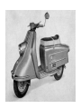
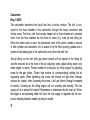
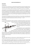
he HEINKEL Motor Scooter was named the "TOURIST"
because, in its design, great care was taken to combine utmost riding comfort and
manoeuvrability with excellent driving characteristics. By using high quality material
and best craftmanship we have done all in our power to give you a vehicle which we
are sure will be a pleasure to you. But we need your co-operation in order to make
this pleasure last for a long time.
We ask you, therefore, in your own interest, to study this Instruction Manual carefully
and to apply it accordingly. When perusing it you will find many useful hints and
following these will save you a great deal of trouble.
Please give your special attention to the running-in instructions, the recommendations
concerning oil-changing, battery maintenance and the lubrication diagram. Recommended Service Inspections — according to our Service Manual — should be carried
out regularly. Should you, at any time, require additional technical information, please
contact your local HEINKEL Dealer, who will be glad to assist you.
It is our aim to make sure that your HEINKEL Scooter gives you entire satisfaction
ERNST HEINKEL AKTIENGESELLSCHAFT
January 1965
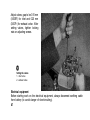
Service
D e p a r t m e n t
THE HEINKEL SERVICE ORGANISATION
with numerous branches in many countries will always gladly assist you with advice
and the dealer who sold you this Scooter will readily give you the personal service which goes with it.
Wherever you see the "HEINKEL SERVICE" Sign, your Tourist Scooter will get careful attention.
At these Service Stations, trained and skilled mechanics with Special tools take
care of your TOURIST and ample spares are always available.
4
Please do not forget that your TOURIST needs regular service inspections. A comprehensive Service Schedule extending to 70.000 miles has been designed for your
guidance, and the service checks involved have been listed and explained in our
(brown) Service Booklet.
The life and trouble-free Service given by your HEINKEL TOURIST depends to a
large extent upon the Running-in and Service Instructions being closely followed.
Comply carefully with these instructions and your TOURIST will never let you down.
5
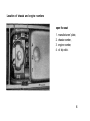
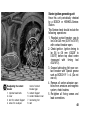
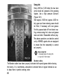
Location of chassis and engine numbers
open the seat:
1.
2.
3.
4.
manufacturers' plate,
chassis number,
engine number,
oil dip stick.
6
chassis number
engine number
Number of steering lock key (i. e.
number indicated on key head)
NOTE! The key for steering lock and luggage compartment can only be replaced
if you quote the key number. Therefore enter your key number in this booklet.
7
At Sports Meetings and Endurance Trials held in Europe and against fierce motorcycle competition HEINKEL TOURIST Scooters always gain an impressive share
of awards.
Thus from 1958 through 1961 HEINKEL TOURIST riders received the following
awards in 151 INTERNATIONAL and NATIONAL meetings:
414 GOLD MEDALS
124 SILVER MEDALS
68 BRONZE MEDALS
83 GOLD TEAM AWARDS
19 SILVER TEAM AWARDS
7 BRONZE TEAM AWARDS
8
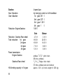
TECHNICAL DATA
Engine
Mode of Operation
Model
Output
Number of cylinders
Arrangement of cylinder
Bore
Stroke
Swept capacity
Compression ratio
Valve arrangement
Valve clearance when engine cold
Lubrication system
Cooling System
Ignition
Type of ignition
Dynamo
9
4-stroke o. h. v.
407 A-1
9.5 h. p. at 5750 r. p. m.
1
vertical
60 mm (2.36") diam.
61.5 mm (2.42")
174 cc
1:7.4
overhead valves
inlet 0.15 mm (0.0059"), exhaust 0.20 mm
(0.0079")
oil-bath splashing lubrication
blower cooling
Battery-magneto with automatic timing
Dynastart unit "BOSCH"
(AZ/DAQ 90/12 1700+0,2 R)
Retarded ignition
Thermal coefficient of spark plug
Spark gap
Contact breaker gap
Spark plug thread
Carburettor
Needle carburettor with accelerator pump
Carburettor passage
Main jet
Idling jet
Needle jet
Position of needle
Jet needle with cone
Float chamber insert
Air screw
Air filter
Clutch
Clutch Operation
0.6 to 0.8 mm (0.0236" to 0.0315") before
t. d. c. (using timing tool 404/W 10)
10° before t.d.c.
225
0.5 to 0.6 mm (0.02" to 0.024")
0.40 to 0.45 mm (0.0157" to 0.0177")
M 14x1.25
BING-Type 1/20/55
20 mm (0.787")
85
30
2.66
3
20x1.65 0
No.3
11/2 turns open (set to best idling)
special paperfilter
oil-bath immersed, multiple-disc clutch
by hand on left handlebar
10
Gearbox
Gear Operation
Gear reduction
Reduction: Engine-Gearbox
Reduction: Gearbox-Rear wheel
Total reduction: 1st gear
2nd gear
3rd gear
4th gear
Power transmission:
Engine-Gearbox
Gearbox-Rear wheel
Hill-climbing capacity in 1st gear
11
4-speed type
by twist-grip control on left handlebar
1st gear 3.51 :1
2nd gear 2.07 :1
3rd gear 1.38:1
4th gear 1
:1
1.88:1
Solo
Sidecar
2.73:1
18.05:1
10.60:1
7.10:1
5.13:1
3.10:1
20.50:1
12.02:1
8.06:1
5.83:1
endless 3/8"x3/8" pitch chain
(56 links, endless)
1
/ 2 " x 5 / 1 6 " Single roller chain
(70 links, endless) solo and sidecar
approx. 3 2 % (at total weight of 250 kg)
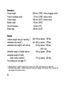
Chassis
Frame
Engine Suspension
Front wheel Suspension
Rear wheel Suspension
Handlebars
Brakes
Brake controls
Stand
Wheels
Rims
Tyres
torsion-free tubular steel
elastic three-point rubber Suspension
swing fork with two hydraulic telescopic
shock absorbers
swinging arm with fully enclosed chain
running in oil-bath; spring leg with
hydraulic telescopic shock absorber
shell handlebar unit with incorporated
speedometer
mechanical internally expanding drum
brakes; drum diameter 140 mm (5.51")
width
25 mm (0.984")
front wheel: by hand lever
rear wheel: by foot-operated pedal
centre stand
interchangeable
2.45-10 split flat-base rims
4.00x10"
12
Dimensions
Overall length
Overall handlebar width
Overall height
Saddle height
Ground clearance
Wheel base
Weights
Unladen weight, ready for travelling 1)
admissible total weight2)
admissible total weight2) with side-car
admissible weight of loaded side-car
admissible weight of trailer
(trailer without brakes!!)
For loading plan, see page 18.
1
)
2
2020 mm
710 mm
1000 mm
750 mm
145 mm
1380 mm
(79.53") without luggage carrier
(27.95") without mirror
(39.37") without mirror
(29.53")
(5.70")
(54.33")
solo 148 kg (approx. 329 Ibs.)
solo 350 kg (approx. 778 Ibs.)
450 kg (approx. 1000 Ibs.)
(with 3 up)
146 kg (approx. 325 Ibs.)
115 kg (approx. 225 Ibs.)
Unladen weight = weight of vehicle alone, ready to be driven, with lubricant, fuel and tools.
) Admissible total weight = unladen weight plus riders and luggage. With side-car fitted, includes the
extra weight of the side-car alone.
13
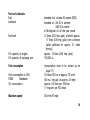
Fuel and Lubricants
Fuel
Lubricant
Fuel tank
Oil capacity of engine
Oil capacity of swinging arm
Fuel consumption
Fuel consumption to DIN
70030
Standards
Oil consumption
Maximum speed
branded fuel, at least 82 octane (ROZ)
branded oil, SA 40 in summer
SAE 30 in winter
or Multigrade oil all the year round
12 litres (2.65 Imp. gals.) of which approx.
1.7 litres (0.38 Imp. gals.) form a reserve
(latter sufficient for approx. 31 miles
driving)
approx. 1.5 litres (2.65 Imp. pints)
150-200 cc.
(consumption chart to be looked up on
page 17)
3.0 litres/100 km at approx. 70 km/h
(94 m.p. Imp.gal. at approx. 43 mph)
approx. 0.5 litres per 1000 km
(1 Imp.pint. per 700 miles)
92 km/h (57 mph)
14
Standard Equipment
12 Volt
Electrical equipment
2; each 6V10/11 Ah.
flat batteries
140 mm ø with Bilux bulb 35/35 Watts
built-in headlamp
4 Watts
parking light
5 Watts
tail light with licence plate light
18 Watts
braking light
18 Watts
blinking light
blinking tell-tale light
2 Watts
charging tell-tale light
2 Watts
speedometer light
2 Watts
combined light-, ignition- and
combined unit incorporated in front
starting-switch
shield
wide-scale speedometer
in handlebar unit
overtaking signal light
switch on handlebar
steering lock
on frame
Luggage hook
on front shield
Extra equipment
Spare wheel
rear luggage carrier
rear view mirror
In the interest of technical progress, we reserve the right to make modifications.
15
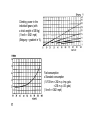
DIAGRAMS
Performance and torque
(1 PS = 1 DIN hp)
(1 mkg = 7.233 ft Ib)
(1 U/min = 1 r.p.m.)
Number of engine revolutions when
driving in the individual gears
(1 U/min = 1 r.p.m.)
(1 km/h = 0.621 mph)
16
Climbing power in the
individuell gears (with
a total weight of 250 kg)
(1 km/h = 0.621 mph)
(Steigung = gradient in %)
Fuel consumption
x Standard consumption
(1 l/100 km = 282 m. p. Imp. gals.
= 235 m. p. US. gals.)
(1 km/h = 0.621 mph)
17
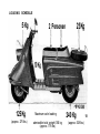
LOADING SCHEDULE
5 Kg
125 Kg
(approx. 275 Ibs.)
25 Kg
2 Personen
Maximum axle loading
admissible total weight 350 kg
(approx. 778 Ibs.)
240 Kg
(approx. 528 Ibs.)
18
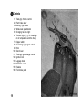
Controls
1.
2.
3.
4.
5.
6.
7.
8.
9.
10.
11.
12.
13.
14.
15.
16.
19
Twist-grip throttle control
Front brake lever
Blinking light switch
Wide-scale speedometer
Charging tell-tale light
Tell-tale light (e. g. for headlight
or oil temperature and the like)
Dipper switch
Overtaking light signal switch
Horn
Clutch lever
Twist-grip gear change control
Ignition lock
Luggage hook
Handlebar lock
Fusebox
Foot brake pedal
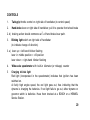
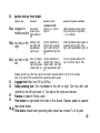
CONTROLS
1.
Twist-grip throttle control on right side of handlebar (to control speed)
2.
Hand-brake lever on right side of handlebar; pull it to operate front wheel brake
2. d) braking action should commence at 1/4 of hand brake lever path.
3.
Blinking light switch on right side of handlebar
(to indicate change of direction)
3. e) lever up = left-hand blinker flashing
lever in middle position = off-position
lever down = right-hand blinker flashing
4.
Wide-scale speedometer with built-in kilometer (or mileage) counter
5.
Charging tell-tale light
Red light (incorporated in the speedometer) indicates that ignition has been
switched on.
At fairly high engine speed, the red light goes out, thus indicating that the
dynamo is charging the batteries. If red light fails to go out, either dynamo or
governor switch is defective. Have them checked at a BOSCH or a HEINKEL
Service Station.
20
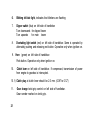
6.
Blinking tell-tale light, indicates that blinkers are flashing
7.
Dipper switch (blue) on left side of handlebar
Turn downwards for dipped beam
Turn upwards
for main beam
8.
Overtaking light switch (red) on left side of handlebar. Same is operated by
alternately pushing and releasing red button. Operative only when ignition on.
9.
10.
Horn (green) on left side of handlebar.
Push button. Operative only when ignition on.
Clutch lever on left side of handlebar. If compressed, transmission of power
from engine to gearbox is interrupted.
10. f) Clutch play at clutch lever should be 2-3 mm. (0.08" to 0.12")
11.
21
Gear change twist-grip control on left side of handlebar.
Gear number marked on twist grip.
12.
Ignition lock on front shield
Ignition key
removed
12. a) engaged in
middle position
all electric
power consumers switched
off
12. b) turn key to the
right
parking Iight,
rear light and
speedometer
iight are on.
pushed in until
resistance is felt
ignition on, control
Iight on
ignition switched on;
control light, parking
Iight, rear light and
speedometer light are
on
pushed in beyond resistance
starter operates engine (start
only with gears in 0-position.,
i. e. in neutral)
starter operates engine (gears in
neutral!) parking light, rear
light and speedometer light on
ignition switched on,
Do only operate starter with
control light, main or
key in position 12a) or 12b)
dipper beam, rear light
and speedometer light
on
Release ignition key after the engine has startet. Operate starter only for 5-10 seconds
max., then wait for 30 seconds before operating starter again.
12. c) turn key to the
left
main- or dipperbeam on, rear
Iight and speedometer Iight on.
13.
14.
Luggage hook. Max load 10 kg (22 Ibs.).
Safety steering lock. Turn handlebar to the left or right. Turn key with lock
cylinder to the left and push in. Turn key to the right and remove.
15.
Fusebox. 4 fuses of 8 Amp. each.
16.
Foot brake on right-hand front side of foot board. Depress pedal to operate
rear wheel brake.
16.g) Foot brake: should start operating after pedal has covered 1/5 of its path.
22
RUNNING-IN AND DRIVING INSTRUCTIONS
The running-in period is of vital importance to the future Service life and the
reliability of your scooter. Even parts, which have been machined with utmost care,
need a certain time for bedding down, and this can only be achieved by a very
careful running-in of your scooter. It is, therefore, in your own interest that we
advise you not to drive at the maximum speed recommended for running-in time
except for very brief periods (a few seconds), after which you should throttle down
again. The more often you repeat this procedure, the sooner all parts will bed down
and the sooner your scooter will have completed its running-in stage. Therefore,
the length of time required for the running-in period, not only depends on the
mileage driven but, to a great extent, also on the way your scooter is run in. During
this period, try to avoid main highways because on these you are quite often induced to speeding. It would be best to drive on secondary roads, because on these
driving usually calls for more frequent gear changing and corresponding closing
and opening of the throttle. Do not permit the engine to labour in high gears, but
change down to a Iower gear in good time in order to avoid too sudden a drop
of engine speed. The engine should always turn freely.
1st gear
up to 12 m. p. h.
2nd gear
from 12 to 20 m. p. h.
3rd gear
from 20 to 30 m. p.h.
4th gear
from 30 to 45 m. p. h.
Even after covering the initial 1250 miles, do not immediately drive at top speed;
instead let the engine get used to it by progressively increasing your speed and by
driving at full throttle for brief intervals only. On long descents leave ignition on
and change down to Iower gear.
23
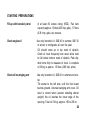
STARTING PREPARATIONS
Fill-up with branded petrol
of at least 82 octane rating (ROZ). Fuel tank
capacity approx. 12 litres (2.65 Imp. gals.), 1.7 litres
(0.38 Imp. gals.) are reserve.
Check engine oil
Use only branded oil; SAE 40 in summer, SAE 30
in winter or multigrade all over the year.
Oil should come up to top mark of dipstick.
Check oil level frequently and never allow level
to fall below bottom mark of dipstick. Push dipstick home fully to measure oil level. A complete
oil filling is approx. 1.5 litres (2.65 Imp. pints).
Check oil in swinging arm
Use only branded oil; SAE 40 in summer and winter.
Tilt scooter to the left side, until the foot board
touches ground. Unscrew swinging arm cover. Oil
level is correct when (scooter standing almost
upright) the oil reaches the Iower edge of the
opening. Total oil filling: approx. 150 to 200 cc.
24
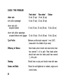
CHECK TYRE PRESSURE
driver solo
with pillion passenger
Front wheel
Rear wheel
Sidecar
1.0 atü (15 psi) 1.8 atü (26 psi)
1.0 atü (15 psi) 2.0 atü (29 psi)
driver solo with
occupied sidecar
1.0 atü (15 psi) 2.5 atü (36 psi) 1.5 atü (22 psi)
driver with pillion passenger,
occupied sidecar and luggage
Tyre Profile:
Efficiency of Brakes:
1.2 atü (18 psi) 2.5 atü (36 psi) 1.5 atü (22 psi)
Minimum profile depth required 1 mm (0.04")
(measured in the middle of tyre cover)
Hand brake action should start once brake lever
has covered 1/4 of its path. Rear brake action
should start once foot brake pedal has covered
1
/5 of its path.
Steering:
Should have no play and should move with ease.
Screws and Bolts:
Should be well-tightened on wheels, engine and
control levers.
25
Lights and Signal:
Main beam, dipper beam, parking light, tail
light, braking light, blinking lights and horn
should work.
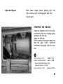
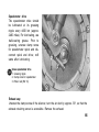
STARTING THE ENGINE
Open the inspection lid on the righthand side of the rear cowling giving
access to the fuel tap.
Open the fuel tap.
Before starting the engine make sure
that the gear control (left-hand
handlebar twist-grip) is set to neutral.
lever pointing to left:
closed (= Zu)
lever in vertical position:
open (= Auf)
tank will discharge down to the
reserve of approx. 1.7 litres
lever pointing to right:
reserve {= Res.)
26
When the engine Open and dose the throttle twist-grip a few times briefly. Then
is cold
push in the ignition key (red light comes on) beyond resistance
to operafe Starter, at the same time slightly opening the throttle
until engine Starts. After starting, release ignition key. Control
engine revolutions by throttle twist-grip on handlebar.
When the engine is warm
Push in key beyond resistance,
at the same time slightly opening
throttle on handlebar until engine Starts. After starting release
ignition key. Control engine revs
by throttle twist grip.
Starting the engine
1. Ignition key
(drücken = push)
2. Twist-grip throttle control
3. Twist-grip gear control
set to O (neutral)
27
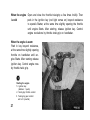
DRIVING AND Ol
Starting
the scooter
Place one foot in front of stand to avoid movement of same. Then grip the handlebars and roll
scooter easily off its stand. Seat yourself comfortably on the scooter.
When the engine has been started (neutral gear),
at Iow number of engine revolutions pull clutch
lever and shift to first gear. Open throttle gradually and slowly release clutch lever (to let in the
clutch). Control driving speed by twist grip
throttle control.
Shifting into higher
gears
The four speed gearbox is operated easily and
smoothly by twist-grip on handlebar. Engage
gears gently and do not force them into position.
At a speed of approx. 12 mph, close throttle,
disengage clutch, shift to 2nd gear, open throttle
again and at the same time let in the clutch
gently. Proceed likewise at a speed of 24 mph in
order to change up into 3rd gear, and at 31 mph
for 4th gear.
28
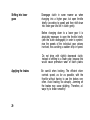
Shifting into Iower
gears
Disengage clutch in same manner as when
changing into a higher gear, but open throttle
briefly (according to speed) and then shift down
into Iower gear and let in clutch gently.
Before changing down to a Iower gear it is
absolutely necessary to open the throttle briefly
(with the clutch disengaged) in order to synchronize the speeds of the individual gear pinions
involved, thus avoiding a sudden drop in speed.
Do not drive with slightly depressed clutch,
instead of shifting to a Iower gear, because this
would cause premature wear of clutch plates.
Applying the brakes
29
Be careful when braking. The efficient driver
controls speed, as far as possible, with the
throttle without having to use the brakes very
often. Avoid braking too abruptly. Jamming on
the brakes may cause skidding. Therefore, always try to brake smoothly!
Avoid locking of wheels because locked wheels
have less braking power. Try always to use both
brakes at the same time. Do not brake while
negotiating curves, but when approaching them.
Always shiftdown to Iower gear on steep slopes
and, if necessary, use front and rear wheel brake
alternately, so as to avoid overheating of brakes.
In Iow gear, the four-stroke engine of your HEINKEL Tourist will take over a large part of the
braking.
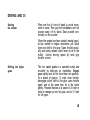
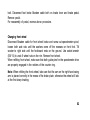
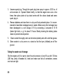
Stopping and parking
To slow down scooter, close the throttle, brake
gently down, at the same time disengage the
clutch and shiftgears into neutral position. Never
stop with gears engaged, because otherwise the
engine will stall. Remove ignition key; close fuel
tap if stopping for quite some time.
Putting scooter on stand
Hold the handlebars and, using your foot, press
stand to the ground and pull the scooter slightly
backwards until the stand catch is reached.
Parking the scooter thus becomes mere child's
play as you do not have to lift the scooter from
the ground.
30
Note! For parking the scooter, both legs of central stand should touch the ground simultaneously
so as to distribute the weight of the scooter
evenly and thus avoid damage to stand.
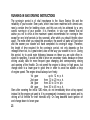
SUGGESTIONS AS TO DRIVING
Driving properly is a decisive factor also for the life span and operating costs
of your scooter. Adapt your driving speed to circumstances prevailing in town and
country traffic. Driving at a steady speedy pace will result in the very same speed
average as driving at a frequently varying pace. Driving unnecessarily fast is unwise.
When driving in mountain regions (descents, gradients) be sure to gear down in time
so that the number of engine revolutions will not fall too much. The engine should
turn but not labour. When driving downhill avail yourself of the braking power of
the 4-stroke engine; change down to the same gear you would use when going uphill.
This makes for added safety and at the same time keeps your brakes efficient. When
going downhill never switch off the ignition.
31
Translation of the above data
see page 80
32
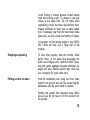
DESCRIPTION OF THE ENGINE
Crankshaft
The crankshaft is suspended by two ball bearings. The chain wheel for driving the
clutch (and thus the gears) is located on the left-hand side of the crankshaft. Starterignition-generating unit, ignition regulator and fan wheel are mounted on the
right-hand side of the crankshaft. The big end of the connecting rod is roller bearing
suspended, the small end is fitted with a bronce bush.
The light metal alloy piston is equipped with 2 compression rings and 1 oil scraper
ring.
Valve Operation
The armoured o. h. valves are mounted in the light metal alloy cylinder head, V-shape.
The valves are operated from the camshaft by drag arms, push rods and rocker arms.
Lubrication
Engine, clutch and gears are combined in one block and have a joint oil chamber.
They are lubricated by a simple oil splashing System.
Change oil according to lubrication plan!
33
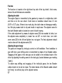
Clutch
The multiple-disc clutch, oil-bath immersed, is mounted on the clutch spindle. The
engine output is transmitted from engine to clutch by a pitch chain. The clutch is
operated from the clutch lever on the handlebar by an adjustable Bowden cable,
fitted to the clutch worm.
Gear Box
The gears are fitted inside the crankcase and the gear wheels are permanently
engaged. The individual gears are operated by the gear change twist-grip control
(left side of handlebar). Gear change operating is transmitted from the twist-grip
through adjustable Bowden cables to the gear lever, which latter transmits it on to
the control segment and the gear change control cylinder. This cylinder is provided
with grooves into which the guide pins of both gear shift forks engage. The forks,
guiding the gear pinions, cause the claws to mesh with the corresponding pairs of
sprocket wheels, thereby achieving the required gear reduction.
Swinging Arm
The rear wheel shaft is driven by a pitch chain - from the small chain wheel of the
drive shaft to the big chain wheel of the rear wheel shaft. The chain, being fully
enclosed in the swinging arm, is oilbath-immersed.
Check oil level in swinging arm as per lubrication schedule and, if necessary,
change oil.
34
35
BING-Carburettor Type 1/20/46
Needle Position
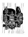
Description and Component List of the Bing-Carburettor Type 1/20/55
A
Carburettor housing
F3 Pump piston
K1 Air regulating screw
A2 Evaporator air bore
F4 Valve plate
K3 Spring
B
F5 Spring
N
B1 Cover thread
G Pump jet needle
N1 Clamp screw
B2 Adjusting screw
G1 Clamp bracket
U
B3 Nut
H Main jet
U1 Float chamber cover
C
Cover plate
Gas piston
Clamp ring
Float chamber
H2 Cover screw
W Float
C2 Gas piston return spring
I
X
C3 Adjuster screw
I1 Idling jet return screw
E
I2
Gasket
K
Idling jet
Mixing chamber insert
F2 Pump needle jet
Idling jet
Float needle
Y1 Banjo connention
(petrol pipe connector)
36
Carburettor
Bing 1/20/55
The carburettor transforms the liquid fuel into a fuel-air mixture. The fuel is conveyed to the float chamber of the carburettor through the banjo connection and
hollow screw. The float, with float needle, keeps fuel in float chamber at a constant
level; from the float chamber the fuel flows to screw (H2), main jet and idling jet.
When the intake valve is open, the downward move of the piston creates a vacuum
in both cylinder and carburettor. Air is sucked in by the filter opening, passes over a
system of fuel-leading jets in the carburettor and is thus fed with fuel.
During idling run the fuel (with gas piston closed) will be tapped at the idling jet
and the required air at the bore of the air adjusting screw (adjust idling speed only
when engine is warm). Pre-set number of revolutions for idling engine by adjusting
screw for the gas piston. Obtain best mixture by correspondingly setting the air
regulating screw. When tightening this screw, the mixture will get richer (through
reduced air intake); when loosening the screw, it will get thinner (through increased
air intake). Correctly set, the idling engine will run smoothly and steadily. The fuel
supply at full or almost full engine Performance is determined by the main jet. When
the engine is not operating under full load, the fuel supply is regulated by the reciprocal interplay between needle jet and jet needle.
37
The HEINKEL Tourist carburettor is equipped with an accelerator pump. It injects a
small quantity of fuel into the mixing chamber whenever the slide is opened. Thus
the fuel pump makes for smooth transition — regulating richness of the fuel-air mixture
when the throttle is opened rapidly.
If, with a cold engine, the throttle is opened several times the fuel injections will
provide for easy starting.
The accelerator pump is combined with the pump needle jet; the Iower enlarged
cylinder part takes up pump piston with valve plate, pump spring and - at the
bottom - the main jet. The whole set is protected by the cover screw H2.
Do not modify factory-standard carburettor setting and be sure to use only factoryrecommended jet sizes.
Starter-ignition-generating unit
It is advisable to pay Special attention to the ignition and lighting System, as the
reliability of the engine largely depends on it. From time to time have this equipment checked by a specialist. Removal and reassembly of this unit should be carried
out only at a HEINKEL- or BOSCH-service Workshop so as to avoid damage to
crankshaft and dynamo.
38
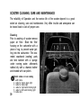
SCOOTER CLEANING, CARE AND MAINTENANCE
The reliability of Operation and the service life of the scooter depend to a great
extent on cleaning, care and maintenance. Very offen trouble and annoyance can
be traced back to lack of proper care.
Cleaning
Prior to washing of scooter remove
paper air filter. Block the filter
housing on the carburettor with a
piece of rag, to prevent water getting into the carburettor. The enameled coachwork (cowling) parts
are best washed with a sponge
under running water, afterwards
rubbed dry with a chamois leather
and treated with car polish.
39
Electric cables on rear cowling
1. earth cable
2. cable for licence plate light
3. cable for brake light
4. cable for right-hand blinking light
5. cable for left-hand blinking light
6. cable clips
After washing, grease brake joints, centre stand and all moving parts. Use a proprietary chromium polish for the chromium-plated parts.
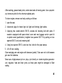
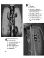
To clean engine, remove rear body cowling as follows:
1. open the seat.
2. disconnect plugs for brake light, tail light and blinking light cables.
3. Applying hex. socket wrench SW 10, unscrew tail retaining bolt with plate. If
scooter is equipped with spare wheel, cover and rear luggage carrier: open lid
on plastic cover (push-button), lengthen box spanner SW 19 by putting on box
spanner SW 21 and undo retaining bolt.
4. Using box spanner SW 10, undo two hex. bolts for the pipe clamps.
5. Lift off rear cowling.
Clean swinging arm and engine with kerosene (petrol). Take care not to let kerosene
get near the batteries.
Never use a high-pressure jet nor play a jet directly on starter-ingnition-generator
unit, regulator, hubs and lever joints, as those parts might be damaged or Start
rusting.
40
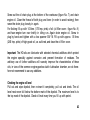
Engine Maintenance
Lubrication is of particular importance with a four-stroke engine and the instructions
for oil-changing must therefore be strictly adhered to. Use only the recommended
branded oils, i. e. multigrade for the whole year round or SAE 40 in summer and
SAE 30 in winter. During the running-in period, change oil as follows:
1st oil-change at 310 miles
2nd oil-change at 625 miles
3rd oil-change at 1250 miles
subsequently
every
1250 miles
Change oil only while the engine is
warm, so that the oil runs out freely.
Put the machine on the stand.
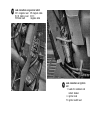
Draining engine oil
1. oil drain screw
2. engine support (left-hand side)
(fitted from bottom)
3. engine support (right-hand side)
(fitted from top)
41
Screw out the oil drain plug at the bottom of the crankcase (figure No. 7) and drain
engine oil. Clean the thread of both plug and bore (in order to avoid seizing); then
screw the drain plug loosely in again.
For flushing fill up with 1.0 litres (1.75 Imp. pints) of oil (oil filler cover - figure No. 8)
and have engine turn over briefly in idling run. Again drain engine oil. Screw in
plug by hand and tighten with a box spanner SW 16. Fill up with approx. 1.5 litres
(2.65 Imp. pints) of high-grade oil, as outlined, and close the oil filler cover.
Important: The HD-oils are lubricants with selected chemical additives which protect
the engine specially against corrosion and prevent formation of residues. The
arbitrary use of further additives will scarcely improve the characteristics of these
oils; in view of the common engine-gearbox-clutch lubrication chamber, we do therefore not recommend to use any additives.
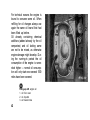
Checking the engine oil Ievel
Pull out and wipe dipstick, then re-insert it completely, pull out and check. The oil
Ievel must never fall below the bottom mark of the dipstick. The maximum Ievel is to
the top mark of the dipstick. Check oil Ievel every time you fill up with petrol.
42
For technical reasons the engine is
bound to consume some oil. When
refilling for oil changes always use
again the same oil brand that had
been filled up before.
Oil already containing chemical
additives (added already by the oil
companies) and oil lacking same
are not to be mixed, as otherwise
engine damage might develop. During the running-in period the oil
consumption of the engine is somewhat higher — normal oil consumption will only start once several 1000
miles have been covered.
Filling-up with engine oil
1. oil filler cover
2. oil dip stick
3. air bleeder tube
43
Changing of oil in swinging arm and
checking of oil level
Tilt scooter to left side, until footboard touches ground, unscrew
swing-arm cover. Drain oil by suction.
Check the links of the chain.
To fill up, use branded oil SAE 40.
Total oil filling approx. 150 to 200
c. c. When oil level is correct, oil
reaches Iower edge of opening
when scooter Stands almost upright. Refit cover of swinging arm
and screw on again.
Check and change oil in swinging arm
1. Fixing nuts
2. Cover for swinging arm
(Ölstand = oil level)
Carburettor cleaning
Occasional cleaning of the carburettor will become necessary. The greatest care
should be taken in dismantling.
Do not dismantle the accelerator pump and pump needle jet set.
44
Wash and flush all the individual
parts in petrol, blow through the Jets
and then re-assemble. Do not modify factory-standard carburettor setting. Readjust needle position and
air regulating screw in accordance
with factory instructions. If you
should have any difficulty with the
carburettor setting, do not hesitate
to call on your HEINKEL-Service Station.
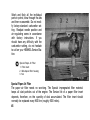
Special Paper Air Filter
1. Filter insert
2. Bell-shaped filter housing
3. Nut
Special Paper Air Filter
The paper air filter needs no servicing. The Special impregnated filter material
keeps all dust particles out of the engine. The Service life of a paper filter insert
depends, therefore, on the quantity of dust accumulated. The filter insert should
normally be replaced every 8000 km (roughly 5000 miles).
45
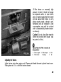
If filter shows an unusually high
amount of dust it should of course
be replaced earlier. In town traffic
and on tarred roads the filter insert
will last about 5000 miles; on very
dusty country roads a drop in performance and an increase in fuel
consumption may well be noticed
after a considerably shorter distance already.
Caution! Do not allow filter insert to
come into confact with liquids (water, petrol, oil etc.)
Special Paper Air Filter, removed and
disassembled
1. Filter support 3. Bell-shaped
4. Disc
2. Filter insert
housing
5. Nut
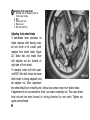
Adjusting the Valves
Adjust valves only when engine cold. Remove air bleed tube and cylinder head cover.
Place piston at t. d. c. with both valves closed.
46
Adjust valves, gap to be 0.15 mm
(0.0059") for inlet and 0.20 mm
(0.0079 )for exhaust valve. After
setting valves, tighten locking
nuts on adjusting screws.
Setting the valves
1. inlet valve
2. exhaust valve
Electrical equipment
Before starting work on the electrical equipment, always disconnect earthing cable
from battery (to avoid danger of shortcircuiting).
47
Re-adjusting the contact
breaker
1. cylinder head bolts
2. cover
3. bolt for contact Support
4. screw for re-adjust-
5.
6.
7.
8.
ment of contact
breaker gap
contact Support
contact breaker lever
lubricating felt
cam
Starter-ignition-generating-unit
Have this unit periodically checked
by a BOSCH or HEINKEL-ServiceStation.
This Service check should include the
following operations:
1. Readjust contact breaker; gap to
be 0.4 to 0.45 mm (0.016" to 0.018")
with contact breaker open.
2. Check ignition. Ignition timing to
be 0.6 to 0.8 mm (0.0236" to
0.0315") before top dead centre
(measured with timing tool
404/W10).
3. Grease lubricating felt near contact breaker with Special grease
such as BOSCH Ft 1 v 4. (Do not
use oil).
4. Remove all carbon abrasion particles from armature and magneto
system; check brushes.
5. Re-tighten all fixing screws and
lead connections.
48
Lead connections on governor switch
30 h magneto lead DF magneto cable
B + 30 battery lead D + 61
50 Starter lead
magneto cable
Lead connections on ignition
coil
1. Leads for condensor and
contact breaker
4. ignition lead
15. ignition switch lead
Ignition coil and governor switch
Ignition coil and governor switch need no servicing. Periodically, however, check
the lead connections on same and, if necessary, tighten them again.
Spark plug
Check spark plug gap every 4000-8000 km
(2.400 to 4.800 miles). It should be 0.5 to 0.6
mm (0.020" to 0.024"). The spark plug is
accessible from the luggage boot; push the
little metal flap aside, remove ignition cable
and unscrew spark plug. When again screwing in the spark plug (washer), do so by
hand, using the spanner only for final
tightening, so as not to damage the thread.
Be careful to place washer correctly on plug;
do not secure the plug too tightly. For screwing in, place plug vertically on thread!
Checking the battery
1. Cover
2. Cover screws
3. Acid tester
4. Acid level (3 mm = 1/8 ins.
above top edge of plates)
50
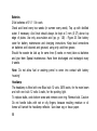
Batteries
2 flat batteries of 6 V 11 Ah each.
Check acid level every two weeks (in summer every week). Top up with distilled
water, if necessary. Acid level should always be kept at 3 mm (0.12") above top
edge of plates. Use only accumulator acid (sp. gr. 1.28) - Figure 25. See battery
cover for battery maintenance and charging instructions. Keep lead connections
on batteries well cleaned and greased, using only acid-free grease.
Should the scooter be laid up for some time (6 weeks or more) take out batteries
and give them Special maintenance. Have them discharged and recharged every
4 weeks.
Note: Do not allow fuel or washing petrol to come into contact with battery
housing!
Headlamp
The headlamp is fitted with one Bilux bulb 12 volts, 35/35 watts, for the main beam
and with one bulb 12 volts 4 watts, for the parking light.
To replace bulbs, undo bottom screw and remove cover ring. Remove bulb. Caution:
Do not handle bulbs with wet or oily fingers, because resulting moisture or oil
fumes will tarnish the headlamp reflector. Use clean rag or tissue paper.
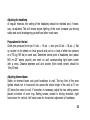
51
Adjusting the headlamp
At regular intervals, the setting of the headlamp should be checked and, if necessary, re-adjusted. This will ensure proper lighting of the road, increase your driving
saftey and avoid endangering yourself and other road users.
Preparations for the test
Check tyre pressure (front tyre 1.0 atü — 15 psi —, rear tyre 2.0 atü — 30 psi —). Set
up scooter on its wheels on level ground and put on a load of either two persons
or of 70 kg (155 Ibs) on each seat. Determine centre point of headlamp face (about
0.65 m = 25" above ground) and mark on wall corresponding light beam centre
with a cross. Distance between wall and scooter (front wheel centre) should be
10m(33 feet).
Adjusting dimmed beam
Switch on dimmed beam and point headlamp to wall. The top limit of the area
lighted should run in horizontal line across the whole length of the wall at 10 cm
(4") below the cross on wall. If correction is necessary, adjust the two setting screws
placed at bottom of cover ring. Setting screws, viewed in driving direction: right
hand screw for vertical, left hand screw for horizontal adjustment of headlamp.
52
Adjusting the headlamp
Adjusting main beam
Switch over to main beam and check if headlamp is correctly set so that cross on
the wall is in centre of lighted area. For correction proceed as explained for
dimmed beam. Cross check with adjustment of dimmed beam.
53
Sidecar Operation
When using the scooter with a sidecar fitted, the headlamp must be re-adjusted.
Proceed according to the foregoing instructions, with the sidecar remaining unladen.
Brake light and tail blinking lights
To replace bulbs of tail-, brake- and tail blinking-lights, undo the 4 bolts and remove
cover of rear lamp assy.
Front blinking Iights
Undo two bolts, remove housing, replace bulb.
Bulbs
Watts
main beam & dipped
beam
35/35
parking light
4
tail light
5
brake light
18
tail blinking light
18
front blinking light
18
control light for blinking
light
2
control light for battery
charging
2
speedometer light
2
Volts
12
12
12
12
12
12
12
12
12
Bilux bulb
bulb socket 9 diam.
bulb
bulb
bulb
bulb
tell-tale lamp bulb,
socket 9 diam.
tell-tale lamp bulb,
socket 9 diam.
tell-tale lamp bulb,
socket 7 diam.
Quantity
1
1
1
1
2
2
1
1
1
54
Fuse box
1 Fuses 8 Amp.
2 lead clamp screws
15 clamp for lead to charging telltale light, blinking light switch and
blinkinq light tell-tale lamp
30 clamp for lead to brake light
switch, handlebar switch 30 and horn
58 clamp for lead to tail light, speedometer light and parking light
56 clamp for lead to handlebar switch
56, for main beam and dipped
beam
Lead connections for headlamp
and blinking light switch
15 lead to fuse-box and tell-tale light
54 lead to blinking light switch
31 earthing lead (brown)
56b lead for dipped beam (yellow)
58 lead for rearlight (grey)
56 headlamp (white)
55
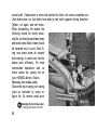
Adjusting the clutch
1. lock nut
2. adjuster screw
3. lock nut
4. clutch cable adjuster screw
Adjusting the gears
1. lock nut
2. adjuster screws for Bowden cable
3. shift lever
4. rubber tube
56
Fuse box
The fuse-box is located at the right-hand top side of the leg shield. Undo screw,
remove lid and the fuses are accessible.
Adjusting the clutch
The engine Output is transmitted to the gearbox by means of a multiple-disc clutch
and then on to the rear wheel. Clutch lever on handlebar should have 2-3 mm
(0.08" to 0.12") play. If there is too much play, the clutch does not disengage readily;
too little play causes clutch to slip and results in rapid wear. The adjuster screw for
the clutch Bowden cable is located on cover of clutch housing.
If the cable adjustment by means of adjuster screw 20/4 has reached its limits, turn
the adjuster screw completely in, loosen hex. nut 20/1 on clutch lever, turn clutch
worm screw 20/2 to the left and tighten hex. nut again. The final adjustment should
now be done with the adjuster screw 20/4.
Adjusting the gear change
The gears are changed by twist-grip control on left handlebar. From handlebar to
gear shift lever, gear shifting action is transmitted by means of two Bowden cables.
Engaging of the gears in the twist-grip can be suited to the individual touch of the
driver by adjusting the setting screw on the twist-grip (located between gear marking
3 and 4).
To obtain easy shifting and engaging of the individual gears, the two Bowden
cables should not be set too loose. The metal sleeves of the Bowden cables should
turn freely, but without play at the adjuster screws.
57
Adjusting the gears (detailed procedure)
Note: "Upward" shifting (1-0-2-3-4) is transmitted by the upper Bowden cable,
"downward" shifting (4-3-2-0-1) is transmitted by the Iower Bowden cable.
1. Set twist-grip to "1"-position; gear lever on crank case must point towards
clutch worm and 1st gear must be engaged.
2. Turn twist-grip slowly to "0"-position (neutral), at the same time moving rear
wheel forward and backwards. Neutral gear must be engaged. If gear wheels
are still in 1st gear, turn upper adjusting screw out until neutral is obtained
(i. e. until rear wheel turns free).
3. Turn twist-grip slowly to "2"-position, at the same time moving rear wheel forward and backwards. 2nd gear must be engaged. If gear wheels are still in
neutral gear, turn upper adjusting screw out until 2nd gear engages.
4. For adjustment of 3rd and 4th gear, proceed correspondingly.
5. For "downward" adjustment, turn twist-grip slowly from "4" to "3"-position
(again moving rear wheel forward and backwards). If necessary turn Iower
adjusting screw out until 3rd gear engages.
6. For adjustment of 2nd, neutral and 1st gear, proceed correspondingly.
7. Should (after adjustment) shifting be too stiff, screw in a little both adjusting
screws equally.
8. Cross-check the individual gears; lock the adjusting screws.
58
Adjusting front wheel brake
1. Adjuster nut for Bowden cable of
front wheel brake
2. Bolt
3. Brake lever nut
4. Brake lever
5. Rim nuts (SW 10)
Adjusting front wheel brake
If handbrake lever produces no
brake response after having covered one fourth of its overall path,
readjust front wheel brake (figure
22). Brake disc and brake lever
with adjuster nut are located on
right side of front wheel.
To readjust, retain bolt with spannerSW10 (this bolt should not move
while brake is being adjusted) and
set adjuster nut. After adjustment
the wheel should turn smoothly and without any uneven noise from brake shoes.
If adjustment of nut has reached its limits, turn same completely out. Then open brake
lever nut and turn lever forward (in driving direction) by one notch. Tighten nut
again and set brake.
59
Adjusting rear brake
1. Lock nut
2. Adjusting screw for
rear brake Bowden cable
3. Brake lever
Adjusting rear wheel brake
The adjuster screw for the rear brake is located on swinging arm (Figure 30). For
readjustment, loosen lock nut and adjust screw. Tighten lock nut again. After adjustment the rear wheel should turn smoothly and without any uneven noise from brake
shoes.
Brake action should commence after foot brake pedal has covered one fifth of its
60
overall path. If adjustment of screw has reached its limits, turn screw completely out.
Undo brake lever nut, turn brake lever back by one notch (against driving direction).
Tighten nut again and set brake.
When dismantling the brakes the
following should be strictly observed:Do not interchange brake shoes
and brake cams. Brake shoes should
be replaced only in pairs. After fitring new brake shoes do several
test brakings, to make sure that the
brakes work efficiently. For more
complicated operations such as
brake repairs etc. please call on
your HEINKEL-Service Station.
Removing foot brake pedal
Disconnect return spring, turn spring
plate as indicated by arrow on
figure No. 24, remove pedal pivot
Removing the foot brake pedal
1. Spring plate with pivot bolt
61
bolt. Disconnect foot brake Bowden cable both on brake lever and brake pedal.
Remove pedal.
For reassembly of pedal, reverse above procedure.
Changing front wheel
Disconnect Bowden cable for front wheel brake and screw out speedometer spiral;
loosen both axle nuts until the washers come off the recesses on front fork. Tilt
scooter to right side until the footboard rests on the ground. Use socket wrench
(SW 14) to undo 5 wheel nuts on the rim. Remove front wheel.
When refitting front wheel, make sure that both guide pins for the speedometer drive
are properly engaged in the notches of the counter ring.
Note: When refitting the front wheel, take care that the cam on the right hand swing
arm is placed correctly in the recess of the brake plate; otherwise the wheel will lock
at the first sharp braking.
62
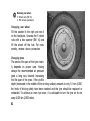
Removing rear wheel
1. Wheel nuts (SW 14)
2. Rim screws (weldea-in)
Changing rear wheel
Tilt the scooter fo the right and rest it
on the footplate. Unscrew the 5 wheel
nuts with a box spanner (SW 14) and
lift the wheel off the hub. For reassembly, reverse above procedure.
Changing tyres
The service life span of the tyres mainly depends on proper care. Having
always the recommended air pressure
goes a long way towards increasing
the life span of the tyres. If the profile
depth (measured in the middle of the running surface) amounts to only 1.0 mm (0.04")
the limits of driving safety have been reached and the tyre should be replaced or
retreaded. To achieve an even tyre wear, it is advisable to turn the tyre on its rim
every 4.000 km (2.500 miles).
63
Removing tyres
Tyre changing is very easy, as the wheel is composed of two split rims, held together
by bolts and nuts. When removing tyre and tube never use sharp tools (screwdriver etc.)
Note: Never undo rim nuts, when tyres are still inflated as otherwise tyres likely to
blow off.
Unscrew valve cap and by means of the reversed cap, screw out valve insert, deflate
tyre, unscrew nut from the valve and push valve back into rim. Place wheel flat on the
ground and, by treading on it, loosen tyre bead all around the rim. Take off 5 nuts
with spanner (SW 10) and pull both rims off tyre.
Fitting tyres
Tube and tyre beads should be rubbed with talc so as to prevent their sticking to rims.
Inflate tube a little and put it into tyre without folds,the valve pointing upwards. Place
tyre with inserted tube flat on the ground and insert the split rim half which provides
the valve bore. Center valve and screw on valve nut. Put on remaining split rim half
and screw on with 5 nuts. Before tightening, check whether the two split rim halves
are a perfect fit in their inner diameter, so as to prevent difficulties when putting
wheel back on hub. Inflate tyre and by letting the wheel bounce on the ground
several times, make sure that both beads fit correctly on rim. After further inflating
(see page 25, checking tyre pressure) the guide line on the tyre bead should be evenly
spaced all around the rim.
64
Swing fork
Every 2.000 km (1.200 miles) the two lever
joints should be greased at the greasing
nipples. Use a high pressure lubricant.
(Figure 32/1).
After approx. 8.000 km (approx. 4.800 miles) upper and Iower steering races should
be filled, if necessary, with new grease.
For this purpose take off front wheel cowling, remove swing fork, clean and grease
races and balls. Reassemble without play.
The above operations can best be carried
out by HEINKEL agents who are equipped
to ensure that the reassembly is carried
out properly.
Grease swing fork
1. Greasing nipple for swing fork
2. Cap nut for front wheel
Bowden cables
The Bowden cables have been properly lubricated with special grease before leaving
the factory. It is, nevertheless, advisable to lubricate them at regular intervals so as
to keep them in perfect working order.
65
Speedometer drive
The speedometer drive should
be lubricated at its greasing
nipple every 4.000 km (approx.
2.400 miles). For lubricating, use
ball-bearing grease. Prior to
greasing, unscrew clamp screw
for speedometer spiral and disconnect spiral and drive; refit
same after lubricating.
Grease speedometer drive
1. Greasing nipple
2. Clamp screw for speedometer
3. Wheel nuts (SW 14)
Exhaust assy
Unscrew the clamp screw of the silencer, turn the air duct by approx. 90°, so that the
exhaust retaining screw is accessible. Remove the exhaust.
66
Exhaust
1. Fixing screw
2. Clamp screw for
exhaust silencer
Winter Driving and Operation
If you drive your scooter during the
winter, take care to drive according to road conditions and apply
brakes very cautiously.
If the average temperature drops
below + 5° C. (40° F) the engine
must be filled up with winter oil
SAE 30 (provided no multigrade oil
is used all year).
At temperatures below freezing
point the Bowden cables should be
lubricated with a lightweight oil, to avoid freezing of the cables.
The batteries have been kept small for reasons of weight; therefore they need special
care in winter, when the engine needs more starting current from the batteries than
in summer.
67
SUMMER DRIVING AND OPERATION UNDER TROPICAL CONDITIONS
When driving in very hot weather or in tropical countries, both the inspection lid on
right side of rear cowling - which gives access to carburettor and fuel tap - and the
seat should be opened after every stop to provide Ventilation and cooling. Acid level
in the batteries should be checked every week, and, if necessary, batteries should
be topped up with distilled water.
STORING OF SCOOTER
If your scooter is not to be used for a fairly long period (wintering, or for any other
reason) the following operations should be carried out:
1. Drive engine until warm, (approx. 10-20 km = 6-12 miles), drain engine oil, fill
up with 1.0 litre (1.75 Imp. pints) of anti-corrosion oil; have engine turn briefly.
2. Close fuel tap, disconnect fuel pipe, drain float chamber.
68
3. Unscrew spark plug. Through the spark plug bore spray in approx. 20-30 cc. of
anti-corrosion oil. Operate Starter briefly, so that the engine turns over a few
times; then place piston at top dead centre with the valves closed and screw
spark plug in.
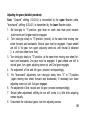
4. Remove batteries and store them in a dry and frost-protected place. It is recommended to have them recharged every 4 weeks. Before every third recharge have
them discharged to a cell voltage of 1.8 by connecting a consumer of 15 W
(brake light bulb, e. g.) for about 10 hours. Merely draining the battery plates
does not prevent decomposition.
5. Clean scooter thoroughly and coat chromium-plated parts with acid-free grease.
6. Store scooter in a dry room on a stand so that the tyres (inflated) are off the
ground.
Taking the scooter out of storage
Run the engine until it is warm; drain the anti-corrosion oil and fill up with 1.5 litres
(2.65 Imp. pints) of branded oil, check and make sure that all connections, screws
and nuts are tight.
69
Breakdowns
I. Engine will not start though operated according to the instructions on page 26
refill tank
1. Fuel tank empty
2. Fuel tap closed or not set for open fuel tap or set for reserve
reserve
3. Fuel system blocked
clear system by blowing through it with
compressed air
4. Jets blocked
clear jets by blowing through (do not dismantle accelerator pump)
close fuel tap, open throttle fully, depress
5. Warm engine "overflooded"
starter button. Within a short time the mixdue to over-application of
ture will be ignitable and engine will start.
throttle
Open fuel tap again
6. Ignition switched on, red control
lamp does not come on:
charge battery
a) battery flat
b) control lamp burned out
replace control lamp
70
7. Break in lead
D+61-15
(between governor switch and
ignition starter).
8. Spark plug fouled, defective or
gap too wide
9. Contact breaker points dirty or
worn, contact breaker rocker
arm sticking
10. Ignition coil defective
11. Condenser defective (blue, arclike contact spark)
eliminate break
clean or replace plug, correct gap to 0.5 to
0.6 mm (0.02" to 0.024")
clean contact breaker points, reset or replace, clean contact breaker rocker arm
pivot
replace ignition coil
replace condenser
II. Starter does not turn or scarcely turns engine
1. Battery Iow or flat
re-charge battery
2. Battery leads corroded
clean, tighten and grease battery leads
3. Short-circuit in wiring System
have wiring checked at a Service Station
4. Magneto coil in regulator
Have magneto coil and wiring checked by
disconnected
BOSCH or HEINKEL service Station.
71
III. Engine cuts out and stops suddenly
1. fuel tank empty
fill up with fuel
2. fuel in tank down to reserve
put fuel tap at reserve position
level
3. fuel pipe clogged
clean fuel pipe by blowing through
4. jets clogged
blow through jets (do not dismantle
accelerator pump!)
5. spark plug defective
replace spark plug
6. ignition cable disconnected
reconnect ignition cable
7. contact breaker rocking arm
clean its fulcrum pin render rocking arm
sticking
movable again
IV. Engine runs irregularly
1. plug loose
2. ignition cable defective
3. plug defective
4. contact breaker points dirty or
worn
5. condenser defective
tighten with box spanner (washer)
insulate or renew ignition cable
renew plug
clean, reset or renew contact breaker
renew condenser
72
V. Engine pulling badly and getting hot
1. Wrong sparking plug
fit correct plug (225)
2. Wrong ignition timing
check and adjust (retarded ignition
0.6 to 0.8 mm (0.0236" to 0.0315") before t.
d. c. measured by timing tool 404/W 10)
3. Engine needs oil
check oil level in engine and fill up, if
necessary
4. Carburettor air-fuel mixture too
tighten carburettor clamp bolt and test for
lean (carburettor loosened)
original setting
5. Brakes bind and get hot
re-adjust brakes
VI. Lights not working
1. Loose or defective bulbs
2. Loose cable connections and
leads
3. Bad earthing connection
73
tighten or renew bulbs
tighten
tighten earthing cable
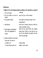
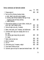
Service, maintenance and lubrication schedule
every
1. Change engine oil
2. Test run with the following functional checks
a) clutch (check for play and correct engaging)
b) switching (check left-hand handlebar twist grip for easy
engaging of gears and easy operating)
c) brakes (efficiency)
3. Check electrical equipment, all current utilisers, including red
control light; check headlight setting
4. Check and adjust valve play, if necessary
5. Battery: check acidity, and, if necessary, add distilled water
6. Corrections which might prove necessary after trial run:
3a) clutch
3b) switching (gear change twist grip control)
3 c) brakes
7. Tighten wheel and axle nuts
8. Check tyre pressure
9. Trial run
10. Check steering, play, if necessary, re-adjust
11. Visual check of wheels and tyres
12. Carburettor, pipes and tap to be cleaned and checked for leaks
km.
2000
miles
1400
2000
1400
2000
2000
2000
1400
1400
1400
2000
1400
2000
2000
2000
4000
1400
1400
1400
2800
4000
2800
74
every
13. Clean spark plug, adjust electrodes, check ignition timing
14. Check contact breaker gap; if necessary, readjust, check
ignition timing
15. Grease lubricating felt on contact breaker cam
16. Retighten engine fixation bolts
17. Lubricate centre stand
18. Lubricate all levers on controls
19. Spray with CARAMBA brake lever and stop light switch
20. Fill rubber boots at the Bowden cable wire ends with grease
21. Clean battery connections and grease with battery grease
22. Thoroughly grease speedometer drive
23. Clean and check for leaks the carburettor, pipes and fuel tap
24. Change paper filter insert
25. Check engine compression
26. Dismantle cooling baffles and, if necessary, grease
27. Visual check of steering races; if necessary, grease
28. Remove front wheel hub with brake nut, change grease
29. Grease front fork
30. Grease Bowden cables
31. Render mobile brake nut for rear wheel and grease
32. Change oil in swinging arm
75
km
4000
miles
2800
4000
4000
4000
4000
4000
4000
4000
4000
4000
8000
8000
8000
8000
8000
8000
8000
8000
8000
8000
2800
2800
2800
2800
2800
2800
2800
2800
2800
5000
5000
5000
5000
5000
5000
5000
5000
5000
5000
Table of contents
Preface
Service
Location of chassis and engine
numbers
Technical data
Diagrams
Loading schedule
Controls
Running-in and driving instructions
Starting preparations
Check tyre pressure
Starting the engine
Driving and operation of controls
Suggestions as to driving
Description of the engine
Crankshaft
Valve Operation
Lubrication
Clutch
Gear box
Swinging arm
3
4
6
9
16
18
19
23
24
25
26
28
31
33
33
33
33
34
34
34
Carburettor
Starter-ignition-generating unit
Scooter cleaning, care and
maintenance
Engine maintenance
Checking the engine oil level
Changing of oil in swinging arm
Carburettor cleaning
Special Paper Air Filter
Adjusting the Valves
Electrical equipment
Starter-ignition-generating unit
Ignition coil and governor switch
Spark plug
Batteries
Headlamp
Adjusting the headlamp
Fuse-box
Adjusting the clutch
Adjusting the gears
(detailed procedure)
35
38
39
41
42
44
44
45
46
47
48
50
50
51
51
52
57
57
58
76
Adjusting front wheel brake
Adjusting rear wheel brake
Removing foot brake pedal
Changing front wheel
Changing rear wheel
Changing tyres
Removing tyres
Fitting tyres
Swing fork
Bowden cables
59
60
61
62
63
63
64
64
65
65
Speedometer drive
Exhaust assy
Winter Driving and Operation
Summer Driving and Operation
Storing of scooter
Taking the scooter out of storage
Breakdowns
Service, maintenance and
lubrication schedule
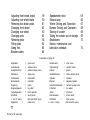
Translation of page 32
Kipphebel
Auslaßventil
Auslaßkrümmer
Zündkerze
Kurbelwelle
Nockenwelle
Kupplung
Kupplungswelle
Vorgelegewelle
Schaltrad
1. und 3. Gang
Kipphebel
=
77
Printed in W.-Germany
=
=
=
=
=
=
=
=
=
=
rocker arm
exhaust valve
exhaust elbow piece
spark plug
crankshaft
camshaft
clutch
lay shaft
clutch spindle
Gear pinion
(first and third gear)
rocker arm
Einlaßventil
Zylinderkopf
Kolben
Einlaßkrümmer
Zylinder
Magnet
Unterbrechernocken
Lüfterrad
Anker
Abtriebswelle
Schaltrad
=
2. und 4. Gang
=
=
=
=
=
=
=
=
=
=
inlet valve
cylinder head
piston
intake elbow piece
cylinder
magneto System
contact breaker cam
fan wheel
armature
driven shaft
Gear pinion
(2nd and 4th gear)
66
66
67
68
68
69
70
74
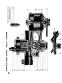
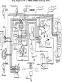
Wiring Diagram for 175 c.c. »HEINKEL-TOURIST« Scooter Type 103 A-2