1
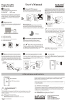
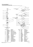
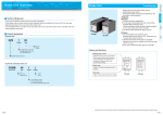
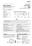
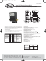
IN-DX:SSS-1000
10/1/10
10:16 AM
Page 1
Bulletin IN-DX
Series DX Differential Pressure Switch
Specifications - Installation and Operating Instructions
1-13/64
[45.85]
59/64
[23.50]
1-27/64
[36.30]
2-55/64
[72.59]
4-29/64
[113.03]
1-11/32
[34.04]
47/64
[18.80]
13/64
[5.08]
2X
47/64
[18.54]
1-13/16
3/4 [46.05]
[19.05]
The Series DX is a pressure switch that makes a contact output based on the
differential pressure between two pressure sources. Unit incorporates a SPDT
snap switch in a weatherproof, type 4X enclosure. Series DX features low
differential pressure set points with high single pressure limit.
OPERATING PRINCIPLE
The DX uses opposing diaphragms to sense the high and low pressure. A pivot
mechanism transfers the difference of the two pressures to the switch.
Example
Series
Construction
Wetted Materials
Process Connection
Circuit Options
Range
Options
DX W 1 1 153 2 M
DX
W
1
1
153
1
2
3
4
DXW-11-153-2-M
Differential Pressure
Switch
Weatherproof
Brass/Fluoroelastomer
1/4˝ NPT
SPDT
2.5 to 10 psi
10 to 25 psi
25 to 50 psi
50 to 75 psi
Stainless Steel tag
SST
PRESET Preset set point
1-13/32
[35.56]
2-1/2
35/64
[63.50]
[13.97]
9/16
[14.10]
15/64
[6.00]
SPECIFICATIONS
Service: Compatible gases and liquids.
Wetted Materials: Connection: Brass; Diaphragm: Fluoroelastomer.
Temperature Limits: 30 to 140°F (-1 to 60°C).
Pressure Limits: 200 psig (13.8 bar).
Enclosure Rating: Weatherproof UL type 4X (IP65).
Repeatability: ±2% of full range.
Switch Type: SPDT snap switch.
Electrical Rating: 5A @ 125/250 VAC (~), 5A res. @ 30 VDC (
).
Electrical Connection: Removable terminal block.
Conduit Connection: 0.871˝ diameter hole for 1/2˝ conduit fitting.
Process Connection: 1/4˝ NPT female. Continuous single side only pressure
should not exceed 1.25 x full differential range.
Mounting Orientation: Ports on horizontal plane, ±10°.
Set Point Adjustment: External screw.
Housing Materials: Body: Aluminum; Housing: Polycarbonate; Cover: 300 SS.
Vibration and Shock: Set point repeats after 2.5 Gs, 5 to 500 Hz. Set point
repeats after a 15 Gs, 10 millisecond duration.
Altitude Limit: 6560 ft (2000 m).
Humidity Limit: 80% (non-condensing).
Pollution Degree: 2.
Environment: Intended for indoor and outdoor use.
Weight: 1 lb 3 oz (0.54 kg).
Agency Approvals: CE, UL.
Adjustable Range
psid (bar)
2.5 to 10 (0.17 to 0.69)
10 to 25 (0.69 to 1.72)
25 to 50 (1.72 to 3.45)
50 to 75 (3.46 to 5.17)
Fixed Deadband
psid (bar)
At Low Set Point At High Set Point
1.5 (0.10)
2.5 (0.17)
2.5 (0.17)
3.5 (0.24)
3.5 (0.24)
6.0 (0.41)
6.0 (0.41)
8.0 (0.55)
Approximate Deadbands
DWYER INSTRUMENTS, INC.
P.O. BOX 373 • MICHIGAN CITY, INDIANA 46361, U.S.A.
Phone: 219/879-8000
Fax: 219/872-9057
www.dwyer-inst.com
e-mail: [email protected]
IN-DX:SSS-1000
10/1/10
10:16 AM
Page 2
UNPACKING
Remove the DX from the shipping carton and inspect for damage. If damage is
found, notify the carrier immediately.
NC
NO
COM
INSTALLATION
CAUTION
Insure that the process fluid is compatible with the wetted
materials.
CAUTION
VIEW OF TERMINAL BLOCK
INSIDE SWITCH HOUSING
Do not exceed the maximum device ratings.
CAUTION
Insure that the system is not pressurized before installing or
removing this device or other objects from the system.
Figure 2: Wiring Diagram
WARNING
The DX is to be mounted with the pressure connections horizontal ±10°.
For pipe mounting, mount the unit from the pressure connections to the pipe. Make
sure the piping is properly supported to handle the weight of the pressure switch.
NOTICE
Power must be off while wiring connections are being made.
Installation must be made in accordance with local codes and
regulations.
For surface mounting, mount the unit to the selected surface using the mounting
ear holes provided using two #6 or #8 screws. See the Figure 2 for mounting hole
spacing.
Make sure that connections are connected to the proper port. The high pressure
port is marked with the “+” sign and is on the left side of the unit with the label side
facing you. The low pressure port is marked by the “-“ sign and is the right side of
the unit. Piping or tubing should always be turned into the pressure port, do not turn
the pressure switch. When installing the piping or tubing into the switch always use
a wrench on the flats of the pressure connection. Use pipe thread sealant tape or
other suitable pipe joint compound when making the pressure connection.
Electrical connections are made to the removable terminal block inside the
enclosure. Remove the terminal block from the circuit board for wiring if desired.
Feed stripped and tinned leads through the conduit opening and connect them as
shown in Figure 2. 250V @ 60C 14 to 24 AWG / 2.5 to .25 mm2 wiring with PVC or
equivalent insulation with 94-V0 or FV-0 flammability rating is recommended for the
switch. Replace terminal block after wiring. The DX provides one 0.871˝ diameter
hole for 1/2˝ conduit fitting. The conduit connections must be made such that
condensation is not allowed to enter the sensor housing. If necessary install a
conduit breather drain in a separate conduit body to prevent buildup of moisture.
NOTICE
For weatherproof applications, install directly to conduit or use
the optional cable gland accessory.
SETPOINT ADJUSTMENT
The set point is adjusted with a standard slotted head screw driver.
1) Remove rubber plug over set point adjustment screw located on the right side of
the unit (with the label side facing you).
2) Insert the screw driver to turn the set point adjustment.
3) A clockwise rotation is an increase in differential pressure set point and a
counterclockwise rotation is a decrease in differential pressure set point. (The
set point screw can be turned too far as to fall out; do not turn the screw to the
point that there are no longer any female threads visible in the switch body).
4) Using a pressure source and pressure gauge adjust the set point screw to the
set point desired while monitoring the contact output.
5) Once desired set point is achieved replace set point adjustment cover.
1-11/32
[34.04]
9/16
[14.10]
35/64
2X
47/64 [13.97]
[18.54]
1-13/32
[35.56]
2-1/2
[63.50]
NOTICE
Design a fail-safe system that takes into consideration the
possibility of switch failure, power failure, and operator error.
15/64
[6.00]
Explanation of Symbols:
Symbol
Publication
Figure 2: Mounting Hole Dimensions
ELECTRICAL CONNECTION
A SPDT snap action switch is provided. The output logic is shown in Table 1.
Condition
NO
NC
Differential Pressure Closed Open
Above Set Point
Differential Pressure Open Closed
Below Set Point
~
Description
IEC 50417 - 5031
Direct current
IEC 50417 - 5032
Alternating current
IEC 50417 - 5019
Protective conductor terminal
MAINTENANCE & REPAIR
Inspect and clean switch with water or damp cloth as needed. Disassembly or
modifications made by the user will void the warranty and could impair the
continued safety of the product. If repair is required obtain a Return Goods
Authorization (RGA) number and send the unit, freight prepaid, to the address
below. Please include a detailed description of the problem and conditions under
which the problem was encountered.
Table 1: Switch Action
Dwyer Instruments, Inc.
Attn: Repair Department
102 Indiana Hwy 212
Michigan City, IN 46360
©Copyright 2010 Dwyer Instruments, Inc.
Printed in U.S.A. 10/10
DWYER INSTRUMENTS, INC.
P.O. BOX 373 • MICHIGAN CITY, INDIANA 46361, U.S.A.
Phone: 219/879-8000
Fax: 219/872-9057
FR# M3-443822-00
www.dwyer-inst.com
e-mail: [email protected]