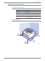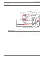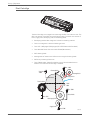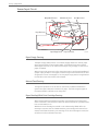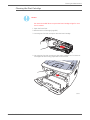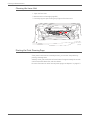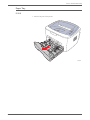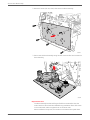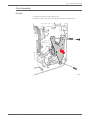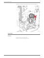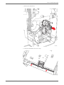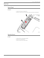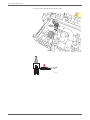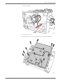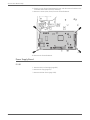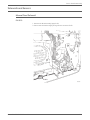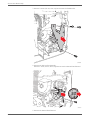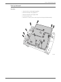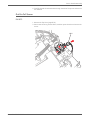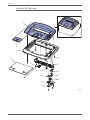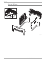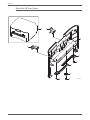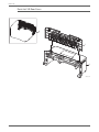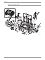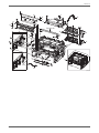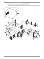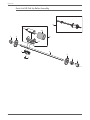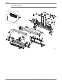
1
Phaser® 3140/3155/3160
Laser Printer
Phaser 3140/3155/3160
Service Manual
®
Phaser 3140/3155/3160
Service Manual
®
Warning
The following servicing instructions are for use by qualified service personnel
only. To avoid personal injury, do not perform any servicing other than that
contained in the operating instructions, unless you are qualified to do so.
First Printing: September 2009
Prepared By:
Xerox Corporation
GPDG Worldwide Product Training and Information
26600 SW Parkway
Wilsonville, OR 97070
© 2009 by Xerox Corporation. All rights reserved.
Unpublished rights reserved under the copyright laws of the United States. Contents of this publication may not be reproduced in any form without
permission of Xerox Corporation.
Copyright protection claimed includes all forms and matters of copyrightable materials and information now allowed by statutory or judicial law or
hereinafter granted, including without limitation, material generated from the software programs which are displayed on the screen such as styles,
templates, icons, screen displays, looks, etc.
Xerox technical training materials and service manuals are intended for use by authorized Xerox service technicians and service partners only and are
not for resale. These materials may not be distributed, copied, or otherwise reproduced without prior written consent from Xerox Corporation.
XEROX®, CentreWare®, Phaser®, PrintingScout™, and Walk-Up® are trademarks of Xerox Corporation in the United States and/or other countries.
Adobe Reader®, Adobe Type Manager®, ATM™, and PostScript® are trademarks of Adobe Systems Incorporated in the United States and/or other
countries.
Apple®, AppleTalk®, Bonjour®, EtherTalk®, LaserWriter®, LocalTalk®, Macintosh®, Mac OS®, and TrueType® are trademarks of Apple Computer, Inc.
in the United States and/or other countries.
HP-GL®, HP-UX®, and PCL® are trademarks of Hewlett-Packard Corporation in the United States and/or other countries.
Windows®, Vista™, and Windows Server™ are trademarks of Microsoft Corporation in the United States and/or other countries.
Novell®, NetWare®, NDPS®, NDS®, Novell Directory Services®, IPX™, and Novell Distributed Print Services™ are trademarks of Novell, Incorporated in
the United States and/or other countries.
SunSM, Sun Microsystems™, and Solaris™ are trademarks of Sun Microsystems, Incorporated in the United States and/or other countries.
SWOP® is a trademark of SWOP, Inc.
UNIX® is a registered trademark in the US and other countries, licensed exclusively through X/Open Company Limited.
As an ENERGY STAR® partner, Xerox Corporation has determined that this product meets the ENERGY STAR guidelines for energy efficiency. The
ENERGY STAR name and logo are registered U.S. marks.
PANTONE® Colors generated may not match PANTONE-identified standards. Consult current PANTONE Publications for accurate color. PANTONE® and
other Pantone, Inc. trademarks are the property of Pantone, Inc. © Pantone, Inc., 2000.
ii
Phaser 3140/3155/3160 Printer Service Manual
Contents
Contents
1 General Information
Introduction and Overview . . . . . . . . . . . . . . . . . . . . . . . . . . . . . . . . . . . . . . . . . . . . . . . . . . . . . . . . . . . . . . . . . . . . . . . . . . . . . . 1-2
Technical Support Information . . . . . . . . . . . . . . . . . . . . . . . . . . . . . . . . . . . . . . . . . . . . . . . . . . . . . . . . . . . . . . . . . . 1-2
Printer Configurations. . . . . . . . . . . . . . . . . . . . . . . . . . . . . . . . . . . . . . . . . . . . . . . . . . . . . . . . . . . . . . . . . . . . . . . . . . . . . . . . . . . 1-3
Parts of the Printer . . . . . . . . . . . . . . . . . . . . . . . . . . . . . . . . . . . . . . . . . . . . . . . . . . . . . . . . . . . . . . . . . . . . . . . . . . . . . . . . . . . . . . 1-5
Front View . . . . . . . . . . . . . . . . . . . . . . . . . . . . . . . . . . . . . . . . . . . . . . . . . . . . . . . . . . . . . . . . . . . . . . . . . . . . . . . . . . . . . 1-5
Rear View . . . . . . . . . . . . . . . . . . . . . . . . . . . . . . . . . . . . . . . . . . . . . . . . . . . . . . . . . . . . . . . . . . . . . . . . . . . . . . . . . . . . . . 1-6
Control Panel. . . . . . . . . . . . . . . . . . . . . . . . . . . . . . . . . . . . . . . . . . . . . . . . . . . . . . . . . . . . . . . . . . . . . . . . . . . . . . . . . . . 1-7
Maintenance Items . . . . . . . . . . . . . . . . . . . . . . . . . . . . . . . . . . . . . . . . . . . . . . . . . . . . . . . . . . . . . . . . . . . . . . . . . . . . . . . . . . . . . 1-9
Consumables . . . . . . . . . . . . . . . . . . . . . . . . . . . . . . . . . . . . . . . . . . . . . . . . . . . . . . . . . . . . . . . . . . . . . . . . . . . . . . . . . . . . . . . . . .1-10
Print Cartridge Life. . . . . . . . . . . . . . . . . . . . . . . . . . . . . . . . . . . . . . . . . . . . . . . . . . . . . . . . . . . . . . . . . . . . . . . . . . . . .1-10
Specifications. . . . . . . . . . . . . . . . . . . . . . . . . . . . . . . . . . . . . . . . . . . . . . . . . . . . . . . . . . . . . . . . . . . . . . . . . . . . . . . . . . . . . . . . . .1-11
Printer Specifications . . . . . . . . . . . . . . . . . . . . . . . . . . . . . . . . . . . . . . . . . . . . . . . . . . . . . . . . . . . . . . . . . . . . . . . . . .1-11
Print Speed. . . . . . . . . . . . . . . . . . . . . . . . . . . . . . . . . . . . . . . . . . . . . . . . . . . . . . . . . . . . . . . . . . . . . . . . . . . . . . . . . . . .1-12
Warm-Up Time . . . . . . . . . . . . . . . . . . . . . . . . . . . . . . . . . . . . . . . . . . . . . . . . . . . . . . . . . . . . . . . . . . . . . . . . . . . . . . . .1-12
Power Save Mode. . . . . . . . . . . . . . . . . . . . . . . . . . . . . . . . . . . . . . . . . . . . . . . . . . . . . . . . . . . . . . . . . . . . . . . . . . . . . .1-12
First Print Output Time . . . . . . . . . . . . . . . . . . . . . . . . . . . . . . . . . . . . . . . . . . . . . . . . . . . . . . . . . . . . . . . . . . . . . . . . .1-12
Memory Specifications. . . . . . . . . . . . . . . . . . . . . . . . . . . . . . . . . . . . . . . . . . . . . . . . . . . . . . . . . . . . . . . . . . . . . . . . .1-12
Environmental Specifications . . . . . . . . . . . . . . . . . . . . . . . . . . . . . . . . . . . . . . . . . . . . . . . . . . . . . . . . . . . . . . . . . . .1-13
Electrical Specifications . . . . . . . . . . . . . . . . . . . . . . . . . . . . . . . . . . . . . . . . . . . . . . . . . . . . . . . . . . . . . . . . . . . . . . . .1-13
Image Specifications . . . . . . . . . . . . . . . . . . . . . . . . . . . . . . . . . . . . . . . . . . . . . . . . . . . . . . . . . . . . . . . . . . . . . . . . . .1-14
Physical Dimensions and Clearances . . . . . . . . . . . . . . . . . . . . . . . . . . . . . . . . . . . . . . . . . . . . . . . . . . . . . . . . . . . .1-15
Mounting Surface Specifications . . . . . . . . . . . . . . . . . . . . . . . . . . . . . . . . . . . . . . . . . . . . . . . . . . . . . . . . . . . . . . .1-16
Media and Tray Specifications. . . . . . . . . . . . . . . . . . . . . . . . . . . . . . . . . . . . . . . . . . . . . . . . . . . . . . . . . . . . . . . . . .1-16
2 Theory of Operation
Operational Overview . . . . . . . . . . . . . . . . . . . . . . . . . . . . . . . . . . . . . . . . . . . . . . . . . . . . . . . . . . . . . . . . . . . . . . . . . . . . . . . . . . . 2-2
System Overview . . . . . . . . . . . . . . . . . . . . . . . . . . . . . . . . . . . . . . . . . . . . . . . . . . . . . . . . . . . . . . . . . . . . . . . . . . . . . . . 2-2
Paper Path . . . . . . . . . . . . . . . . . . . . . . . . . . . . . . . . . . . . . . . . . . . . . . . . . . . . . . . . . . . . . . . . . . . . . . . . . . . . . . . . . . . . . . . . . . . . . 2-3
Paper Feeding . . . . . . . . . . . . . . . . . . . . . . . . . . . . . . . . . . . . . . . . . . . . . . . . . . . . . . . . . . . . . . . . . . . . . . . . . . . . . . . . . . 2-3
Drive Assembly . . . . . . . . . . . . . . . . . . . . . . . . . . . . . . . . . . . . . . . . . . . . . . . . . . . . . . . . . . . . . . . . . . . . . . . . . . . . . . . . . 2-6
Laser Unit . . . . . . . . . . . . . . . . . . . . . . . . . . . . . . . . . . . . . . . . . . . . . . . . . . . . . . . . . . . . . . . . . . . . . . . . . . . . . . . . . . . . . . 2-7
Transfer Roller. . . . . . . . . . . . . . . . . . . . . . . . . . . . . . . . . . . . . . . . . . . . . . . . . . . . . . . . . . . . . . . . . . . . . . . . . . . . . . . . . . 2-7
Print Cartridge. . . . . . . . . . . . . . . . . . . . . . . . . . . . . . . . . . . . . . . . . . . . . . . . . . . . . . . . . . . . . . . . . . . . . . . . . . . . . . . . . . 2-8
Fuser . . . . . . . . . . . . . . . . . . . . . . . . . . . . . . . . . . . . . . . . . . . . . . . . . . . . . . . . . . . . . . . . . . . . . . . . . . . . . . . . . . . . . . . . . . 2-9
Electrical Components . . . . . . . . . . . . . . . . . . . . . . . . . . . . . . . . . . . . . . . . . . . . . . . . . . . . . . . . . . . . . . . . . . . . . . . . .2-10
Sensor Input Circuit. . . . . . . . . . . . . . . . . . . . . . . . . . . . . . . . . . . . . . . . . . . . . . . . . . . . . . . . . . . . . . . . . . . . . . . . . . . .2-16
Driving Circuit . . . . . . . . . . . . . . . . . . . . . . . . . . . . . . . . . . . . . . . . . . . . . . . . . . . . . . . . . . . . . . . . . . . . . . . . . . . . . . . . .2-17
Engine F/W. . . . . . . . . . . . . . . . . . . . . . . . . . . . . . . . . . . . . . . . . . . . . . . . . . . . . . . . . . . . . . . . . . . . . . . . . . . . . . . . . . . .2-18
Phaser 3140/3155/3160 Printer Service Manual
iii
Contents
3 Error Messages and Codes
Introduction . . . . . . . . . . . . . . . . . . . . . . . . . . . . . . . . . . . . . . . . . . . . . . . . . . . . . . . . . . . . . . . . . . . . . . . . . . . . . . . . . . . . . . . . . . . . 3-2
Diagnostics . . . . . . . . . . . . . . . . . . . . . . . . . . . . . . . . . . . . . . . . . . . . . . . . . . . . . . . . . . . . . . . . . . . . . . . . . . . . . . . . . . . . 3-2
Understanding the Control Panel LEDs . . . . . . . . . . . . . . . . . . . . . . . . . . . . . . . . . . . . . . . . . . . . . . . . . . . . . . . . . . . . . . . . . . . 3-3
Jam Errors . . . . . . . . . . . . . . . . . . . . . . . . . . . . . . . . . . . . . . . . . . . . . . . . . . . . . . . . . . . . . . . . . . . . . . . . . . . . . . . . . . . . . . . . . . . . . . 3-5
Clearing Paper Jams . . . . . . . . . . . . . . . . . . . . . . . . . . . . . . . . . . . . . . . . . . . . . . . . . . . . . . . . . . . . . . . . . . . . . . . . . . . . 3-5
Paper Jam 0 . . . . . . . . . . . . . . . . . . . . . . . . . . . . . . . . . . . . . . . . . . . . . . . . . . . . . . . . . . . . . . . . . . . . . . . . . . . . . . . . . . . . 3-8
Paper Jam 1 . . . . . . . . . . . . . . . . . . . . . . . . . . . . . . . . . . . . . . . . . . . . . . . . . . . . . . . . . . . . . . . . . . . . . . . . . . . . . . . . . . .3-10
Paper Jam 2 . . . . . . . . . . . . . . . . . . . . . . . . . . . . . . . . . . . . . . . . . . . . . . . . . . . . . . . . . . . . . . . . . . . . . . . . . . . . . . . . . . .3-11
Paper Rolled on the OPC Drum . . . . . . . . . . . . . . . . . . . . . . . . . . . . . . . . . . . . . . . . . . . . . . . . . . . . . . . . . . . . . . . . .3-13
Tray and Media Problems . . . . . . . . . . . . . . . . . . . . . . . . . . . . . . . . . . . . . . . . . . . . . . . . . . . . . . . . . . . . . . . . . . . . . . . . . . . . . .3-14
Paper Tray Empty Indication with Paper in Tray . . . . . . . . . . . . . . . . . . . . . . . . . . . . . . . . . . . . . . . . . . . . . . . . .3-14
Paper Tray Empty With No Indication. . . . . . . . . . . . . . . . . . . . . . . . . . . . . . . . . . . . . . . . . . . . . . . . . . . . . . . . . . .3-15
Multiple Sheet Feeding . . . . . . . . . . . . . . . . . . . . . . . . . . . . . . . . . . . . . . . . . . . . . . . . . . . . . . . . . . . . . . . . . . . . . . . .3-16
Out Bin Full . . . . . . . . . . . . . . . . . . . . . . . . . . . . . . . . . . . . . . . . . . . . . . . . . . . . . . . . . . . . . . . . . . . . . . . . . . . . . . . . . . .3-17
Print Cartridge Errors . . . . . . . . . . . . . . . . . . . . . . . . . . . . . . . . . . . . . . . . . . . . . . . . . . . . . . . . . . . . . . . . . . . . . . . . . . . . . . . . . . .3-18
Print Cartridge At Or Nearing End Of Life. . . . . . . . . . . . . . . . . . . . . . . . . . . . . . . . . . . . . . . . . . . . . . . . . . . . . . . .3-18
Invalid Print Cartridge . . . . . . . . . . . . . . . . . . . . . . . . . . . . . . . . . . . . . . . . . . . . . . . . . . . . . . . . . . . . . . . . . . . . . . . . .3-19
Toner Empty or Exhausted . . . . . . . . . . . . . . . . . . . . . . . . . . . . . . . . . . . . . . . . . . . . . . . . . . . . . . . . . . . . . . . . . . . . .3-20
Fuser Errors . . . . . . . . . . . . . . . . . . . . . . . . . . . . . . . . . . . . . . . . . . . . . . . . . . . . . . . . . . . . . . . . . . . . . . . . . . . . . . . . . . . . . . . . . . . .3-21
Paper Rolled in the Fuser . . . . . . . . . . . . . . . . . . . . . . . . . . . . . . . . . . . . . . . . . . . . . . . . . . . . . . . . . . . . . . . . . . . . . . .3-21
Fuser Gear Damaged from Overheating. . . . . . . . . . . . . . . . . . . . . . . . . . . . . . . . . . . . . . . . . . . . . . . . . . . . . . . . .3-22
Front Cover Errors . . . . . . . . . . . . . . . . . . . . . . . . . . . . . . . . . . . . . . . . . . . . . . . . . . . . . . . . . . . . . . . . . . . . . . . . . . . . . . . . . . . . . .3-23
Error Indicated When Front Cover is Closed . . . . . . . . . . . . . . . . . . . . . . . . . . . . . . . . . . . . . . . . . . . . . . . . . . . . .3-23
No Error LED Indication for Front Cover . . . . . . . . . . . . . . . . . . . . . . . . . . . . . . . . . . . . . . . . . . . . . . . . . . . . . . . . .3-24
4 General Troubleshooting
Introduction . . . . . . . . . . . . . . . . . . . . . . . . . . . . . . . . . . . . . . . . . . . . . . . . . . . . . . . . . . . . . . . . . . . . . . . . . . . . . . . . . . . . . . . . . . . . 4-2
Reports. . . . . . . . . . . . . . . . . . . . . . . . . . . . . . . . . . . . . . . . . . . . . . . . . . . . . . . . . . . . . . . . . . . . . . . . . . . . . . . . . . . . . . . . . . . . . . . . . 4-2
Printing Demo Page . . . . . . . . . . . . . . . . . . . . . . . . . . . . . . . . . . . . . . . . . . . . . . . . . . . . . . . . . . . . . . . . . . . . . . . . . . . . 4-3
Configuration Report . . . . . . . . . . . . . . . . . . . . . . . . . . . . . . . . . . . . . . . . . . . . . . . . . . . . . . . . . . . . . . . . . . . . . . . . . . . 4-4
Supplies Information Report/Error Information Report . . . . . . . . . . . . . . . . . . . . . . . . . . . . . . . . . . . . . . . . . . . . 4-5
Cleaning Page . . . . . . . . . . . . . . . . . . . . . . . . . . . . . . . . . . . . . . . . . . . . . . . . . . . . . . . . . . . . . . . . . . . . . . . . . . . . . . . . . . 4-7
Servicing Instructions . . . . . . . . . . . . . . . . . . . . . . . . . . . . . . . . . . . . . . . . . . . . . . . . . . . . . . . . . . . . . . . . . . . . . . . . . . . . . . . . . . . 4-8
Measurement Techniques . . . . . . . . . . . . . . . . . . . . . . . . . . . . . . . . . . . . . . . . . . . . . . . . . . . . . . . . . . . . . . . . . . . . . . . . . . . . . . . 4-9
Media-Based Problems . . . . . . . . . . . . . . . . . . . . . . . . . . . . . . . . . . . . . . . . . . . . . . . . . . . . . . . . . . . . . . . . . . . . . . . . . . . . . . . . .4-10
Mis-Pick . . . . . . . . . . . . . . . . . . . . . . . . . . . . . . . . . . . . . . . . . . . . . . . . . . . . . . . . . . . . . . . . . . . . . . . . . . . . . . . . . . . . . . .4-10
Inoperable Printer Troubleshooting . . . . . . . . . . . . . . . . . . . . . . . . . . . . . . . . . . . . . . . . . . . . . . . . . . . . . . . . . . . . . . . . . . . . .4-11
The Printer is Not Responding to the Print Command . . . . . . . . . . . . . . . . . . . . . . . . . . . . . . . . . . . . . . . . . . . .4-11
Power Supply Troubleshooting . . . . . . . . . . . . . . . . . . . . . . . . . . . . . . . . . . . . . . . . . . . . . . . . . . . . . . . . . . . . . . . . . . . . . . . . . .4-12
AC Power Troubleshooting . . . . . . . . . . . . . . . . . . . . . . . . . . . . . . . . . . . . . . . . . . . . . . . . . . . . . . . . . . . . . . . . . . . . .4-12
No Power . . . . . . . . . . . . . . . . . . . . . . . . . . . . . . . . . . . . . . . . . . . . . . . . . . . . . . . . . . . . . . . . . . . . . . . . . . . . . . . . . . . . .4-13
USB Port Testing. . . . . . . . . . . . . . . . . . . . . . . . . . . . . . . . . . . . . . . . . . . . . . . . . . . . . . . . . . . . . . . . . . . . . . . . . . . . . . . . . . . . . . .4-15
USB Port Verification . . . . . . . . . . . . . . . . . . . . . . . . . . . . . . . . . . . . . . . . . . . . . . . . . . . . . . . . . . . . . . . . . . . . . . . . . .4-15
Network Configuration Errors . . . . . . . . . . . . . . . . . . . . . . . . . . . . . . . . . . . . . . . . . . . . . . . . . . . . . . . . . . . . . . . . . . . . . . . . . . .4-16
Send Error. . . . . . . . . . . . . . . . . . . . . . . . . . . . . . . . . . . . . . . . . . . . . . . . . . . . . . . . . . . . . . . . . . . . . . . . . . . . . . . . . . . . .4-16
Operating System and Application Problems. . . . . . . . . . . . . . . . . . . . . . . . . . . . . . . . . . . . . . . . . . . . . . . . . . . . . . . . . . . . .4-17
Common Windows Problems . . . . . . . . . . . . . . . . . . . . . . . . . . . . . . . . . . . . . . . . . . . . . . . . . . . . . . . . . . . . . . . . . . .4-17
SPOOL Error . . . . . . . . . . . . . . . . . . . . . . . . . . . . . . . . . . . . . . . . . . . . . . . . . . . . . . . . . . . . . . . . . . . . . . . . . . . . . . . . . . .4-18
Common Macintosh Problems . . . . . . . . . . . . . . . . . . . . . . . . . . . . . . . . . . . . . . . . . . . . . . . . . . . . . . . . . . . . . . . . . .4-18
Common Linux Problems . . . . . . . . . . . . . . . . . . . . . . . . . . . . . . . . . . . . . . . . . . . . . . . . . . . . . . . . . . . . . . . . . . . . . . .4-19
Common PostScript Problems . . . . . . . . . . . . . . . . . . . . . . . . . . . . . . . . . . . . . . . . . . . . . . . . . . . . . . . . . . . . . . . . . .4-20
iv
Phaser 3140/3155/3160 Printer Service Manual
Contents
5 Print-Quality Troubleshooting
Print-Quality Troubleshooting Overview . . . . . . . . . . . . . . . . . . . . . . . . . . . . . . . . . . . . . . . . . . . . . . . . . . . . . . . . . . . . . . . . . . 5-2
Defects Associated with Specific Components . . . . . . . . . . . . . . . . . . . . . . . . . . . . . . . . . . . . . . . . . . . . . . . . . . . . 5-2
Troubleshooting Print-Quality Checklist. . . . . . . . . . . . . . . . . . . . . . . . . . . . . . . . . . . . . . . . . . . . . . . . . . . . . . . . . . . . . . . . . . . 5-4
Check the Print Cartridge. . . . . . . . . . . . . . . . . . . . . . . . . . . . . . . . . . . . . . . . . . . . . . . . . . . . . . . . . . . . . . . . . . . . . . . . 5-4
Check the Laser Unit . . . . . . . . . . . . . . . . . . . . . . . . . . . . . . . . . . . . . . . . . . . . . . . . . . . . . . . . . . . . . . . . . . . . . . . . . . . . 5-4
Check the Transfer Roller. . . . . . . . . . . . . . . . . . . . . . . . . . . . . . . . . . . . . . . . . . . . . . . . . . . . . . . . . . . . . . . . . . . . . . . . 5-5
Check the Image . . . . . . . . . . . . . . . . . . . . . . . . . . . . . . . . . . . . . . . . . . . . . . . . . . . . . . . . . . . . . . . . . . . . . . . . . . . . . . . 5-5
Print-Quality Troubleshooting Procedures. . . . . . . . . . . . . . . . . . . . . . . . . . . . . . . . . . . . . . . . . . . . . . . . . . . . . . . . . . . . . . . . . 5-8
Print-Quality Defect Definitions. . . . . . . . . . . . . . . . . . . . . . . . . . . . . . . . . . . . . . . . . . . . . . . . . . . . . . . . . . . . . . . . . . 5-8
Repeating Defects . . . . . . . . . . . . . . . . . . . . . . . . . . . . . . . . . . . . . . . . . . . . . . . . . . . . . . . . . . . . . . . . . . . . . . . . . . . . . . 5-9
Printing Begins at Wrong Position . . . . . . . . . . . . . . . . . . . . . . . . . . . . . . . . . . . . . . . . . . . . . . . . . . . . . . . . . . . . . .5-10
Light or Undertone Print . . . . . . . . . . . . . . . . . . . . . . . . . . . . . . . . . . . . . . . . . . . . . . . . . . . . . . . . . . . . . . . . . . . . . . .5-10
Black Print. . . . . . . . . . . . . . . . . . . . . . . . . . . . . . . . . . . . . . . . . . . . . . . . . . . . . . . . . . . . . . . . . . . . . . . . . . . . . . . . . . . . .5-11
Uneven Density . . . . . . . . . . . . . . . . . . . . . . . . . . . . . . . . . . . . . . . . . . . . . . . . . . . . . . . . . . . . . . . . . . . . . . . . . . . . . . .5-13
Background Contamination . . . . . . . . . . . . . . . . . . . . . . . . . . . . . . . . . . . . . . . . . . . . . . . . . . . . . . . . . . . . . . . . . . . .5-14
Ghosting (1). . . . . . . . . . . . . . . . . . . . . . . . . . . . . . . . . . . . . . . . . . . . . . . . . . . . . . . . . . . . . . . . . . . . . . . . . . . . . . . . . . .5-15
Ghosting (2). . . . . . . . . . . . . . . . . . . . . . . . . . . . . . . . . . . . . . . . . . . . . . . . . . . . . . . . . . . . . . . . . . . . . . . . . . . . . . . . . . .5-16
Ghosting (3). . . . . . . . . . . . . . . . . . . . . . . . . . . . . . . . . . . . . . . . . . . . . . . . . . . . . . . . . . . . . . . . . . . . . . . . . . . . . . . . . . .5-17
Ghosting (4). . . . . . . . . . . . . . . . . . . . . . . . . . . . . . . . . . . . . . . . . . . . . . . . . . . . . . . . . . . . . . . . . . . . . . . . . . . . . . . . . . .5-18
Vertical White Lines. . . . . . . . . . . . . . . . . . . . . . . . . . . . . . . . . . . . . . . . . . . . . . . . . . . . . . . . . . . . . . . . . . . . . . . . . . . .5-19
Vertical Lines are Curved . . . . . . . . . . . . . . . . . . . . . . . . . . . . . . . . . . . . . . . . . . . . . . . . . . . . . . . . . . . . . . . . . . . . . . .5-20
Vertical Black Line or Band . . . . . . . . . . . . . . . . . . . . . . . . . . . . . . . . . . . . . . . . . . . . . . . . . . . . . . . . . . . . . . . . . . . . .5-21
Horizontal Black Line or Band. . . . . . . . . . . . . . . . . . . . . . . . . . . . . . . . . . . . . . . . . . . . . . . . . . . . . . . . . . . . . . . . . . .5-22
Black/White Spot . . . . . . . . . . . . . . . . . . . . . . . . . . . . . . . . . . . . . . . . . . . . . . . . . . . . . . . . . . . . . . . . . . . . . . . . . . . . . .5-23
Skew. . . . . . . . . . . . . . . . . . . . . . . . . . . . . . . . . . . . . . . . . . . . . . . . . . . . . . . . . . . . . . . . . . . . . . . . . . . . . . . . . . . . . . . . . .5-24
Stains on the Front of the Page. . . . . . . . . . . . . . . . . . . . . . . . . . . . . . . . . . . . . . . . . . . . . . . . . . . . . . . . . . . . . . . . .5-26
Stains on the Back of the Page . . . . . . . . . . . . . . . . . . . . . . . . . . . . . . . . . . . . . . . . . . . . . . . . . . . . . . . . . . . . . . . . .5-27
Blank Page (1). . . . . . . . . . . . . . . . . . . . . . . . . . . . . . . . . . . . . . . . . . . . . . . . . . . . . . . . . . . . . . . . . . . . . . . . . . . . . . . . .5-28
Blank Page (2). . . . . . . . . . . . . . . . . . . . . . . . . . . . . . . . . . . . . . . . . . . . . . . . . . . . . . . . . . . . . . . . . . . . . . . . . . . . . . . . .5-29
Incomplete Fusing . . . . . . . . . . . . . . . . . . . . . . . . . . . . . . . . . . . . . . . . . . . . . . . . . . . . . . . . . . . . . . . . . . . . . . . . . . . . .5-30
Print-Quality Specifications . . . . . . . . . . . . . . . . . . . . . . . . . . . . . . . . . . . . . . . . . . . . . . . . . . . . . . . . . . . . . . . . . . . . . . . . . . . . .5-31
Skew. . . . . . . . . . . . . . . . . . . . . . . . . . . . . . . . . . . . . . . . . . . . . . . . . . . . . . . . . . . . . . . . . . . . . . . . . . . . . . . . . . . . . . . . . .5-31
Curl . . . . . . . . . . . . . . . . . . . . . . . . . . . . . . . . . . . . . . . . . . . . . . . . . . . . . . . . . . . . . . . . . . . . . . . . . . . . . . . . . . . . . . . . . . .5-31
Registration . . . . . . . . . . . . . . . . . . . . . . . . . . . . . . . . . . . . . . . . . . . . . . . . . . . . . . . . . . . . . . . . . . . . . . . . . . . . . . . . . . .5-31
Noise . . . . . . . . . . . . . . . . . . . . . . . . . . . . . . . . . . . . . . . . . . . . . . . . . . . . . . . . . . . . . . . . . . . . . . . . . . . . . . . . . . . . . . . . .5-31
Image Area . . . . . . . . . . . . . . . . . . . . . . . . . . . . . . . . . . . . . . . . . . . . . . . . . . . . . . . . . . . . . . . . . . . . . . . . . . . . . . . . . . .5-32
Environmental Condition. . . . . . . . . . . . . . . . . . . . . . . . . . . . . . . . . . . . . . . . . . . . . . . . . . . . . . . . . . . . . . . . . . . . . . .5-32
Quality Paper. . . . . . . . . . . . . . . . . . . . . . . . . . . . . . . . . . . . . . . . . . . . . . . . . . . . . . . . . . . . . . . . . . . . . . . . . . . . . . . . . .5-32
Paper Condition . . . . . . . . . . . . . . . . . . . . . . . . . . . . . . . . . . . . . . . . . . . . . . . . . . . . . . . . . . . . . . . . . . . . . . . . . . . . . . .5-32
Printer Condition . . . . . . . . . . . . . . . . . . . . . . . . . . . . . . . . . . . . . . . . . . . . . . . . . . . . . . . . . . . . . . . . . . . . . . . . . . . . . .5-33
6 Adjustments and Calibrations
Adjustments. . . . . . . . . . . . . . . . . . . . . . . . . . . . . . . . . . . . . . . . . . . . . . . . . . . . . . . . . . . . . . . . . . . . . . . . . . . . . . . . . . . . . . . . . . . . 6-2
Altitude Specifications . . . . . . . . . . . . . . . . . . . . . . . . . . . . . . . . . . . . . . . . . . . . . . . . . . . . . . . . . . . . . . . . . . . . . . . . . . 6-2
Phaser 3140/3155/3160 Printer Service Manual
v
Contents
7 Cleaning and Maintenance
Service Maintenance Procedure. . . . . . . . . . . . . . . . . . . . . . . . . . . . . . . . . . . . . . . . . . . . . . . . . . . . . . . . . . . . . . . . . . . . . . . . . . 7-2
Recommended Tools . . . . . . . . . . . . . . . . . . . . . . . . . . . . . . . . . . . . . . . . . . . . . . . . . . . . . . . . . . . . . . . . . . . . . . . . . . . 7-2
Cleaning . . . . . . . . . . . . . . . . . . . . . . . . . . . . . . . . . . . . . . . . . . . . . . . . . . . . . . . . . . . . . . . . . . . . . . . . . . . . . . . . . . . . . . . . . . . . . . . 7-2
Cleaning the Print Cartridge . . . . . . . . . . . . . . . . . . . . . . . . . . . . . . . . . . . . . . . . . . . . . . . . . . . . . . . . . . . . . . . . . . . . . 7-3
Cleaning the Laser Unit . . . . . . . . . . . . . . . . . . . . . . . . . . . . . . . . . . . . . . . . . . . . . . . . . . . . . . . . . . . . . . . . . . . . . . . . . 7-4
Printing the Print Cleaning Page . . . . . . . . . . . . . . . . . . . . . . . . . . . . . . . . . . . . . . . . . . . . . . . . . . . . . . . . . . . . . . . . . 7-4
Maintenance . . . . . . . . . . . . . . . . . . . . . . . . . . . . . . . . . . . . . . . . . . . . . . . . . . . . . . . . . . . . . . . . . . . . . . . . . . . . . . . . . . . . . . . . . . . 7-5
RIP Procedures . . . . . . . . . . . . . . . . . . . . . . . . . . . . . . . . . . . . . . . . . . . . . . . . . . . . . . . . . . . . . . . . . . . . . . . . . . . . . . . . . 7-5
Firmware Updates . . . . . . . . . . . . . . . . . . . . . . . . . . . . . . . . . . . . . . . . . . . . . . . . . . . . . . . . . . . . . . . . . . . . . . . . . . . . . . . . . . . . . . 7-5
Firmware Update Procedures . . . . . . . . . . . . . . . . . . . . . . . . . . . . . . . . . . . . . . . . . . . . . . . . . . . . . . . . . . . . . . . . . . . . 7-5
8 Service Parts Disassembly
Overview . . . . . . . . . . . . . . . . . . . . . . . . . . . . . . . . . . . . . . . . . . . . . . . . . . . . . . . . . . . . . . . . . . . . . . . . . . . . . . . . . . . . . . . . . . . . . . . 8-2
Standard Orientation of the Printer . . . . . . . . . . . . . . . . . . . . . . . . . . . . . . . . . . . . . . . . . . . . . . . . . . . . . . . . . . . . . . 8-2
Preparation . . . . . . . . . . . . . . . . . . . . . . . . . . . . . . . . . . . . . . . . . . . . . . . . . . . . . . . . . . . . . . . . . . . . . . . . . . . . . . . . . . . . 8-3
Notations in the Disassembly Text . . . . . . . . . . . . . . . . . . . . . . . . . . . . . . . . . . . . . . . . . . . . . . . . . . . . . . . . . . . . . . . 8-4
Fastener Types . . . . . . . . . . . . . . . . . . . . . . . . . . . . . . . . . . . . . . . . . . . . . . . . . . . . . . . . . . . . . . . . . . . . . . . . . . . . . . . . . 8-5
Maintenance Items and Consumables . . . . . . . . . . . . . . . . . . . . . . . . . . . . . . . . . . . . . . . . . . . . . . . . . . . . . . . . . . . . . . . . . . . 8-6
Print Cartridge. . . . . . . . . . . . . . . . . . . . . . . . . . . . . . . . . . . . . . . . . . . . . . . . . . . . . . . . . . . . . . . . . . . . . . . . . . . . . . . . . . 8-6
Paper Tray . . . . . . . . . . . . . . . . . . . . . . . . . . . . . . . . . . . . . . . . . . . . . . . . . . . . . . . . . . . . . . . . . . . . . . . . . . . . . . . . . . . . . 8-7
Transfer Roller. . . . . . . . . . . . . . . . . . . . . . . . . . . . . . . . . . . . . . . . . . . . . . . . . . . . . . . . . . . . . . . . . . . . . . . . . . . . . . . . . . 8-8
Pick Up Roller. . . . . . . . . . . . . . . . . . . . . . . . . . . . . . . . . . . . . . . . . . . . . . . . . . . . . . . . . . . . . . . . . . . . . . . . . . . . . . . . . . . 8-9
Fuser . . . . . . . . . . . . . . . . . . . . . . . . . . . . . . . . . . . . . . . . . . . . . . . . . . . . . . . . . . . . . . . . . . . . . . . . . . . . . . . . . . . . . . . . .8-11
Thermistor . . . . . . . . . . . . . . . . . . . . . . . . . . . . . . . . . . . . . . . . . . . . . . . . . . . . . . . . . . . . . . . . . . . . . . . . . . . . . . . . . . . .8-13
Thermostat . . . . . . . . . . . . . . . . . . . . . . . . . . . . . . . . . . . . . . . . . . . . . . . . . . . . . . . . . . . . . . . . . . . . . . . . . . . . . . . . . . .8-14
Fuser Lamp. . . . . . . . . . . . . . . . . . . . . . . . . . . . . . . . . . . . . . . . . . . . . . . . . . . . . . . . . . . . . . . . . . . . . . . . . . . . . . . . . . . .8-15
Heat Roller . . . . . . . . . . . . . . . . . . . . . . . . . . . . . . . . . . . . . . . . . . . . . . . . . . . . . . . . . . . . . . . . . . . . . . . . . . . . . . . . . . . .8-17
Pressure Roller . . . . . . . . . . . . . . . . . . . . . . . . . . . . . . . . . . . . . . . . . . . . . . . . . . . . . . . . . . . . . . . . . . . . . . . . . . . . . . . . .8-20
Covers . . . . . . . . . . . . . . . . . . . . . . . . . . . . . . . . . . . . . . . . . . . . . . . . . . . . . . . . . . . . . . . . . . . . . . . . . . . . . . . . . . . . . . . . . . . . . . . .8-23
Front Cover . . . . . . . . . . . . . . . . . . . . . . . . . . . . . . . . . . . . . . . . . . . . . . . . . . . . . . . . . . . . . . . . . . . . . . . . . . . . . . . . . . .8-23
Top Cover . . . . . . . . . . . . . . . . . . . . . . . . . . . . . . . . . . . . . . . . . . . . . . . . . . . . . . . . . . . . . . . . . . . . . . . . . . . . . . . . . . . . .8-23
Rear Cover . . . . . . . . . . . . . . . . . . . . . . . . . . . . . . . . . . . . . . . . . . . . . . . . . . . . . . . . . . . . . . . . . . . . . . . . . . . . . . . . . . . .8-26
Left Side Cover . . . . . . . . . . . . . . . . . . . . . . . . . . . . . . . . . . . . . . . . . . . . . . . . . . . . . . . . . . . . . . . . . . . . . . . . . . . . . . . .8-27
Right Side Cover . . . . . . . . . . . . . . . . . . . . . . . . . . . . . . . . . . . . . . . . . . . . . . . . . . . . . . . . . . . . . . . . . . . . . . . . . . . . . . .8-28
Disassembly Procedures . . . . . . . . . . . . . . . . . . . . . . . . . . . . . . . . . . . . . . . . . . . . . . . . . . . . . . . . . . . . . . . . . . . . . . . . . . . . . . . .8-29
Tray Holder Pad Assembly. . . . . . . . . . . . . . . . . . . . . . . . . . . . . . . . . . . . . . . . . . . . . . . . . . . . . . . . . . . . . . . . . . . . . .8-29
Laser Unit . . . . . . . . . . . . . . . . . . . . . . . . . . . . . . . . . . . . . . . . . . . . . . . . . . . . . . . . . . . . . . . . . . . . . . . . . . . . . . . . . . . . .8-30
Feeder . . . . . . . . . . . . . . . . . . . . . . . . . . . . . . . . . . . . . . . . . . . . . . . . . . . . . . . . . . . . . . . . . . . . . . . . . . . . . . . . . . . . . . . . . . . . . . . .8-32
Pick Up Roller Assembly . . . . . . . . . . . . . . . . . . . . . . . . . . . . . . . . . . . . . . . . . . . . . . . . . . . . . . . . . . . . . . . . . . . . . . . .8-32
Drive Assembly . . . . . . . . . . . . . . . . . . . . . . . . . . . . . . . . . . . . . . . . . . . . . . . . . . . . . . . . . . . . . . . . . . . . . . . . . . . . . . . .8-35
Clutch Assembly . . . . . . . . . . . . . . . . . . . . . . . . . . . . . . . . . . . . . . . . . . . . . . . . . . . . . . . . . . . . . . . . . . . . . . . . . . . . . . .8-37
Feed Roller . . . . . . . . . . . . . . . . . . . . . . . . . . . . . . . . . . . . . . . . . . . . . . . . . . . . . . . . . . . . . . . . . . . . . . . . . . . . . . . . . . . .8-38
Feed Actuator . . . . . . . . . . . . . . . . . . . . . . . . . . . . . . . . . . . . . . . . . . . . . . . . . . . . . . . . . . . . . . . . . . . . . . . . . . . . . . . . .8-40
Manual Feed Actuator . . . . . . . . . . . . . . . . . . . . . . . . . . . . . . . . . . . . . . . . . . . . . . . . . . . . . . . . . . . . . . . . . . . . . . . . .8-44
Paper Tray Empty Actuator. . . . . . . . . . . . . . . . . . . . . . . . . . . . . . . . . . . . . . . . . . . . . . . . . . . . . . . . . . . . . . . . . . . . .8-47
Electrical . . . . . . . . . . . . . . . . . . . . . . . . . . . . . . . . . . . . . . . . . . . . . . . . . . . . . . . . . . . . . . . . . . . . . . . . . . . . . . . . . . . . . . . . . . . . . .8-51
Control Panel. . . . . . . . . . . . . . . . . . . . . . . . . . . . . . . . . . . . . . . . . . . . . . . . . . . . . . . . . . . . . . . . . . . . . . . . . . . . . . . . . .8-51
Controller Board . . . . . . . . . . . . . . . . . . . . . . . . . . . . . . . . . . . . . . . . . . . . . . . . . . . . . . . . . . . . . . . . . . . . . . . . . . . . . . .8-51
Power Supply Board . . . . . . . . . . . . . . . . . . . . . . . . . . . . . . . . . . . . . . . . . . . . . . . . . . . . . . . . . . . . . . . . . . . . . . . . . . .8-54
Fan . . . . . . . . . . . . . . . . . . . . . . . . . . . . . . . . . . . . . . . . . . . . . . . . . . . . . . . . . . . . . . . . . . . . . . . . . . . . . . . . . . . . . . . . . . .8-58
Solenoids and Sensors. . . . . . . . . . . . . . . . . . . . . . . . . . . . . . . . . . . . . . . . . . . . . . . . . . . . . . . . . . . . . . . . . . . . . . . . . . . . . . . . . .8-59
Manual Feed Solenoid . . . . . . . . . . . . . . . . . . . . . . . . . . . . . . . . . . . . . . . . . . . . . . . . . . . . . . . . . . . . . . . . . . . . . . . . .8-59
Pick Up Solenoid. . . . . . . . . . . . . . . . . . . . . . . . . . . . . . . . . . . . . . . . . . . . . . . . . . . . . . . . . . . . . . . . . . . . . . . . . . . . . . .8-61
Out Bin Full Sensor. . . . . . . . . . . . . . . . . . . . . . . . . . . . . . . . . . . . . . . . . . . . . . . . . . . . . . . . . . . . . . . . . . . . . . . . . . . . .8-63
vi
Phaser 3140/3155/3160 Printer Service Manual
Contents
9 Parts List
Serial Number Format. . . . . . . . . . . . . . . . . . . . . . . . . . . . . . . . . . . . . . . . . . . . . . . . . . . . . . . . . . . . . . . . . . . . . . . . . . . . . . . . . . . 9-2
Using the Parts List . . . . . . . . . . . . . . . . . . . . . . . . . . . . . . . . . . . . . . . . . . . . . . . . . . . . . . . . . . . . . . . . . . . . . . . . . . . . . . . . . . . . . 9-3
Parts Lists . . . . . . . . . . . . . . . . . . . . . . . . . . . . . . . . . . . . . . . . . . . . . . . . . . . . . . . . . . . . . . . . . . . . . . . . . . . . . . . . . . . . . . . . . . . . . . 9-4
Parts List 1.0 Main . . . . . . . . . . . . . . . . . . . . . . . . . . . . . . . . . . . . . . . . . . . . . . . . . . . . . . . . . . . . . . . . . . . . . . . . . . . . . . 9-4
Parts List 2.0 Top Cover . . . . . . . . . . . . . . . . . . . . . . . . . . . . . . . . . . . . . . . . . . . . . . . . . . . . . . . . . . . . . . . . . . . . . . . . . 9-6
Parts List 3.0 Covers. . . . . . . . . . . . . . . . . . . . . . . . . . . . . . . . . . . . . . . . . . . . . . . . . . . . . . . . . . . . . . . . . . . . . . . . . . . . . 9-8
Parts List 4.0 Front Cover . . . . . . . . . . . . . . . . . . . . . . . . . . . . . . . . . . . . . . . . . . . . . . . . . . . . . . . . . . . . . . . . . . . . . . .9-10
Parts List 5.0 Rear Cover . . . . . . . . . . . . . . . . . . . . . . . . . . . . . . . . . . . . . . . . . . . . . . . . . . . . . . . . . . . . . . . . . . . . . . .9-12
Parts List 6.0 Main Frame . . . . . . . . . . . . . . . . . . . . . . . . . . . . . . . . . . . . . . . . . . . . . . . . . . . . . . . . . . . . . . . . . . . . . .9-14
Parts List 7.0 Drive Assembly (Model 3140). . . . . . . . . . . . . . . . . . . . . . . . . . . . . . . . . . . . . . . . . . . . . . . . . . . . . .9-20
Parts List 7.1 Drive Assembly (Models 3155/3160) . . . . . . . . . . . . . . . . . . . . . . . . . . . . . . . . . . . . . . . . . . . . . . .9-22
Parts List 8.0 Pick Up Roller Assembly . . . . . . . . . . . . . . . . . . . . . . . . . . . . . . . . . . . . . . . . . . . . . . . . . . . . . . . . . . .9-24
Parts List 9.0 Fuser . . . . . . . . . . . . . . . . . . . . . . . . . . . . . . . . . . . . . . . . . . . . . . . . . . . . . . . . . . . . . . . . . . . . . . . . . . . . .9-26
Parts List 10.0 Paper Tray . . . . . . . . . . . . . . . . . . . . . . . . . . . . . . . . . . . . . . . . . . . . . . . . . . . . . . . . . . . . . . . . . . . . . .9-30
Xerox Supplies and Accessories . . . . . . . . . . . . . . . . . . . . . . . . . . . . . . . . . . . . . . . . . . . . . . . . . . . . . . . . . . . . . . . . . . . . . . . . .9-32
10 Wiring
Plug/Jack Locators . . . . . . . . . . . . . . . . . . . . . . . . . . . . . . . . . . . . . . . . . . . . . . . . . . . . . . . . . . . . . . . . . . . . . . . . . . . . . . . . . . . . .10-2
Map 1 - Controller Board (3140) . . . . . . . . . . . . . . . . . . . . . . . . . . . . . . . . . . . . . . . . . . . . . . . . . . . . . . . . . . . . . . . .10-4
Map 2 - Controller Board (3155) . . . . . . . . . . . . . . . . . . . . . . . . . . . . . . . . . . . . . . . . . . . . . . . . . . . . . . . . . . . . . . . .10-5
Map 3 - Controller Board (3160B/3160N) . . . . . . . . . . . . . . . . . . . . . . . . . . . . . . . . . . . . . . . . . . . . . . . . . . . . . . .10-6
Map 4 - 110V and 220V Power Supply Boards . . . . . . . . . . . . . . . . . . . . . . . . . . . . . . . . . . . . . . . . . . . . . . . . . . .10-7
Component Locator Diagrams . . . . . . . . . . . . . . . . . . . . . . . . . . . . . . . . . . . . . . . . . . . . . . . . . . . . . . . . . . . . . . . . . . . . . . . . . .10-8
Map 5 - Sensors . . . . . . . . . . . . . . . . . . . . . . . . . . . . . . . . . . . . . . . . . . . . . . . . . . . . . . . . . . . . . . . . . . . . . . . . . . . . . . .10-9
Map 6 - Motor, Solenoids, and Fan . . . . . . . . . . . . . . . . . . . . . . . . . . . . . . . . . . . . . . . . . . . . . . . . . . . . . . . . . . . . 10-10
Wiring Diagrams. . . . . . . . . . . . . . . . . . . . . . . . . . . . . . . . . . . . . . . . . . . . . . . . . . . . . . . . . . . . . . . . . . . . . . . . . . . . . . . . . . . . . 10-11
Notations Used in the Wiring Diagrams . . . . . . . . . . . . . . . . . . . . . . . . . . . . . . . . . . . . . . . . . . . . . . . . . . . . . . . 10-11
Phaser 3140 Wiring . . . . . . . . . . . . . . . . . . . . . . . . . . . . . . . . . . . . . . . . . . . . . . . . . . . . . . . . . . . . . . . . . . . . . . . . . . . . . . . . . . 10-14
3140 System Connections. . . . . . . . . . . . . . . . . . . . . . . . . . . . . . . . . . . . . . . . . . . . . . . . . . . . . . . . . . . . . . . . . . . . 10-14
3140 Controller Board Wiring . . . . . . . . . . . . . . . . . . . . . . . . . . . . . . . . . . . . . . . . . . . . . . . . . . . . . . . . . . . . . . . . 10-15
3140 Laser Unit Wiring . . . . . . . . . . . . . . . . . . . . . . . . . . . . . . . . . . . . . . . . . . . . . . . . . . . . . . . . . . . . . . . . . . . . . . 10-16
3140 Power Supply Wiring . . . . . . . . . . . . . . . . . . . . . . . . . . . . . . . . . . . . . . . . . . . . . . . . . . . . . . . . . . . . . . . . . . . 10-17
Phaser 3155 Wiring . . . . . . . . . . . . . . . . . . . . . . . . . . . . . . . . . . . . . . . . . . . . . . . . . . . . . . . . . . . . . . . . . . . . . . . . . . . . . . . . . . 10-18
3155 System Connections. . . . . . . . . . . . . . . . . . . . . . . . . . . . . . . . . . . . . . . . . . . . . . . . . . . . . . . . . . . . . . . . . . . . 10-18
3155 Controller Board Wiring . . . . . . . . . . . . . . . . . . . . . . . . . . . . . . . . . . . . . . . . . . . . . . . . . . . . . . . . . . . . . . . . 10-19
3155 Laser Unit Wiring . . . . . . . . . . . . . . . . . . . . . . . . . . . . . . . . . . . . . . . . . . . . . . . . . . . . . . . . . . . . . . . . . . . . . . 10-20
3155 Power Supply Wiring . . . . . . . . . . . . . . . . . . . . . . . . . . . . . . . . . . . . . . . . . . . . . . . . . . . . . . . . . . . . . . . . . . . 10-21
Phaser 3160 Wiring . . . . . . . . . . . . . . . . . . . . . . . . . . . . . . . . . . . . . . . . . . . . . . . . . . . . . . . . . . . . . . . . . . . . . . . . . . . . . . . . . . 10-22
3160 System Connections. . . . . . . . . . . . . . . . . . . . . . . . . . . . . . . . . . . . . . . . . . . . . . . . . . . . . . . . . . . . . . . . . . . . 10-22
3160 Controller Board Wiring . . . . . . . . . . . . . . . . . . . . . . . . . . . . . . . . . . . . . . . . . . . . . . . . . . . . . . . . . . . . . . . . 10-23
3160 Laser Unit Wiring . . . . . . . . . . . . . . . . . . . . . . . . . . . . . . . . . . . . . . . . . . . . . . . . . . . . . . . . . . . . . . . . . . . . . . 10-24
3160 Power Supply Wiring . . . . . . . . . . . . . . . . . . . . . . . . . . . . . . . . . . . . . . . . . . . . . . . . . . . . . . . . . . . . . . . . . . . 10-25
A Reference
Acronyms and Abbreviations . . . . . . . . . . . . . . . . . . . . . . . . . . . . . . . . . . . . . . . . . . . . . . . . . . . . . . . . . . . . . . . . . . . . . . . . . . . . A-2
Phaser 3140/3155/3160 Printer Service Manual
vii
Contents
viii
Phaser 3140/3155/3160 Printer Service Manual
Service Terms
Manual Terms
Various terms are used throughout this manual to either provide additional
information on a specific topic or to warn of possible danger present during a
procedure or action. Be aware of all symbols and terms when they are used, and
always read Note, Caution, and Warning statements.
Note
A note indicates an operating or maintenance procedure, practice or condition
that is necessary to efficiently accomplish a task.
A note can provide additional information related to a specific subject or add
a comment on the results achieved through a previous action.
Caution
A caution indicates an operating or maintenance procedure, practice or
condition that, if not strictly observed, results in damage to, or destruction of,
equipment.
Warning
A warning indicates an operating or maintenance procedure, practice or
condition that, if not strictly observed, may result in personal injury.
Product Terms
Caution: A personal injury hazard exists that may not be apparent. For example, a
panel may cover the hazardous area.
Danger: A personal injury hazard exists in the area where you see the sign.
Phaser 3140/3155/3160 Printer Service Manual
ix
Symbols Marked on the Product
Warning. Danger invisible laser radiation when open.
Avoid direct exposure to beam.
Hot surface on or in the printer. Use caution to avoid
personal injury.
Warning. Use caution to avoid personal injury.
Use caution (or draws attention to a particular
component). Refer to the manual(s) for information.
Do not touch the OPC Drum.
Do not expose the item to sunlight.
Do not tilt the Print Cartridge.
0°C
32°F
35°C Do not expose item to high temperature.
95°F
Recycle the item.
x
Phaser 3140/3155/3160 Printer Service Manual
Power Safety Precautions
Power Source
For 115 VAC printers, do not apply more than 127 volts RMS between the supply
conductors or between either supply conductor and ground. For 230 VAC printers,
do not apply more than 254 volts RMS between the supply conductors or between
either supply conductor and ground. Use only the specified power cord and
connector. This manual assumes that the reader is a qualified service technician.
Plug the three-wire power cord (with grounding prong) into a grounded AC outlet
only. If necessary, contact a licensed electrician to install a properly grounded
outlet. If the product loses its ground connection, contact with conductive parts
may cause an electrical shock. A protective ground connection by way of the
grounding conductor in the power cord is essential for safe operation.
Disconnecting Power
Warning
Turning the power Off using the power switch does not completely de-energize
the printer. Disconnect the power cord from the printer. Disconnect the power
cord by pulling the plug, not the cord.
Disconnect the Power Cord in the following cases:
•
if the power cord or plug is frayed or otherwise damaged,
•
if any liquid or foreign material is spilled into the product,
•
if the printer is exposed to any excess moisture,
•
if the printer is dropped or damaged,
•
if you suspect that the product needs servicing or repair,
•
whenever you clean the product.
Phaser 3140/3155/3160 Printer Service Manual
xi
Electrostatic Discharge Precautions
Some semiconductor components, and the respective sub-assemblies that contain
them, are vulnerable to damage by Electrostatic Discharge (ESD). These
components include Integrated Circuits (ICs), Large-Scale Integrated circuits
(LSIs), field-effect transistors, and other semiconductor chip components. The
following techniques will reduce the occurrence of component damage caused by
static electricity.
Be sure the power is Off to the chassis or circuit board, and observe all other safety
precautions.
xii
•
Immediately before handling any semiconductor components assemblies,
drain the electrostatic charge from your body. This can be accomplished by
touching an earth ground source or by wearing a wrist strap device connected
to an earth ground source. Wearing a wrist strap will also prevent
accumulation of additional bodily static charges. Be sure to remove the wrist
strap before applying power to the unit under test to avoid potential shock.
•
After removing a static sensitive assembly from its anti-static bag, place it on
a grounded conductive surface. If the anti-static bag is conductive, you may
ground the bag and use it as a conductive surface.
•
Do not use freon-propelled chemicals. These can generate electrical charges
sufficient to damage some devices.
•
Do not remove a replacement component or electrical sub-assembly from its
protective package until you are ready to install it.
•
Immediately before removing the protective material from the leads of a
replacement device, touch the protective material to the chassis or circuit
assembly into which the device will be installed.
•
Minimize body motions when handling unpacked replacement devices.
Motion such as your clothes brushing together, or lifting a foot from a
carpeted floor can generate enough static electricity to damage an electrostatically sensitive device.
•
Handle IC’s and Erasable Programmable Read-Only Memories (EPROM’s)
carefully to avoid bending pins.
•
Pay attention to the direction of parts when mounting or inserting them on
Printed Circuit Boards (PCB’s).
Phaser 3140/3155/3160 Printer Service Manual
Service Safety Summary
General Guidelines
For qualified service personnel only: Refer also to the preceding “Power Safety
Precautions” on page xi.
Use care when servicing with power: Dangerous voltages may exist at several
points in this product. To avoid personal injury, do not touch exposed connections
and components while power is On. Disconnect power before removing the covers
or replacing components.
Do not wear jewelry: Remove jewelry prior to servicing. Rings, necklaces, and
other metallic objects could come into contact with dangerous voltages and
currents.
Ozone: During normal operation, this machine produces ozone gas. The amount
of ozone produced does not present a hazard to the operator. However, it is
advisable that the machine be operated in a well ventilated area.
Warning Labels
Read and obey all posted warning labels. Throughout the printer, warning labels
are displayed on potentially dangerous components. As you service the printer,
check to make certain that all warning labels remain in place.
Safety Interlocks
Make sure all covers are in place and all Interlock switches are functioning correctly
after you have completed a printer service call. If you bypass an Interlock Switch
during a service call, use extreme caution when working on or around the printer.
Class 1 Laser Product
The Phaser 3140/3155/3160 is certified to comply with Laser Product
Performance Standards set by the U.S. Department of Health and Human Services
as a Class 1 Laser Product. This means that this product does not emit hazardous
laser radiation; which is possible only because the laser beam is totally enclosed
during all modes of customer operation. When servicing the printer or laser unit,
follow the procedures specified in this manual and there will be no hazards from
the laser.
Maintenance
Cleaning
Before cleaning this product, unplug the product from the electrical outlet. Always
use materials specifically designated for this product, the use of other materials
may result in poor performance and create a hazardous situation. Do not use
aerosol cleaners; they may be explosive and flammable under certain conditions.
Phaser 3140/3155/3160 Printer Service Manual
xiii
Print Cartridge
The product contains a dry image cartridge that is recyclable. Under various state
and local laws, it may be illegal to dispose of the cartridge into the municipal
waste. Check with the local waste officials for details on recycling options or the
proper disposal procedures.
Fuses
Warning
Do not install a fuse of a different type or rating. Installing the wrong type or
rating of fuse can cause overheating and a risk of fire.
Part Replacement
Only use genuine Xerox approved spare parts or components to maintain
compliance with legislation and safety certification.
Assembly Precautions
Use extreme care during assembly. Check all harnesses to ensure they do not
contact moving parts and can not get trapped between components.
xiv
Phaser 3140/3155/3160 Printer Service Manual
Servicing Electrical Components
Before starting any service procedure, switch the printer power Off and unplug the
Power Cord from the wall outlet. If you must service the printer with power applied,
be aware of the potential for electrical shock.
Warning
Do not touch any electrical component unless you are instructed to do so by a
service procedure.
Servicing Mechanical Components
When servicing mechanical components within the printer, manually rotate the
drive assemblies, rollers, and gears.
Warning
Do not try to manually rotate or manually stop the drive assemblies while the
printer motor is running.
Servicing Fuser Components
Warning
This printer uses heat to fuse the toner image to paper. The Fuser is very hot. Turn
the printer power Off and wait for the Fuser to cool before attempting to service
the Fuser or adjacent components.
Phaser 3140/3155/3160 Printer Service Manual
xv
Moving the Printer
Warning
Parts of the printer are hot. Wait at least 30 minutes for the printer to cool before
moving or packing the printer.
Warning
Back injury could result if you do not lift the printer properly.
The printer can be lifted by one person. Use proper lifting and handling
techniques when moving the printer.
7.41 kg
16.34 lb.
s3160-078
When shipping the printer, repack the printer using the original packing material
and boxes or a Xerox packaging kit. Instructions for repacking the printer are
included in the kit. If you do not have all the original packaging, or are unable to
repackage the printer, contact your local Xerox service representative.
Caution
Failure to properly repackage the printer for shipment can result in damage to
the printer. Damage to the printer caused by improper packaging is not
covered by the Xerox warranty, service agreement, or Total Satisfaction
Guarantee.
xvi
Phaser 3140/3155/3160 Printer Service Manual
Regulatory Information
Xerox has tested this product to electromagnetic emission and immunity
standards. These standards are designed to mitigate interference caused or
received by this product in a typical office environment.
United States (FCC Regulations)
This equipment has been tested and found to comply with the limits for a Class B
digital device, pursuant to Part 15 of the Federal Communications Commission
(FCC) Rules. These limits are designed to provide reasonable protection against
harmful interference in a residential installation. This equipment generates, uses,
and can radiate radio frequency energy. If it is not installed and used in
accordance with these instructions, it may cause harmful interference to radio
communications. However, there is no guarantee that interference will not occur in
a particular installation. If this equipment does cause harmful interference to radio
or television reception, which can be determined by turning the equipment Off
and On, the user is encouraged to try to correct the interference by one or more of
the following measures:
•
Reorient or relocate the receiver (device being interfered with).
•
Increase the separation between the printer and the receiver.
•
Connect the equipment into an outlet on a circuit different from that which
the receiver is connected.
•
Consult the dealer or an experienced radio/television technician for help.
Any changes or modifications not expressly approved by Xerox could void the
user's authority to operate the equipment. To ensure compliance with Part 15 of
the FCC rules, use shielded interface cables.
Canada (Regulations)
This Class B digital apparatus complies with Canadian ICES-003.
Cet appareil numérique de la classe B est conforme à la norme NMB-003 du
Canada.
Phaser 3140/3155/3160 Printer Service Manual
xvii
European Union
The CE mark applied to this product symbolizes Xerox’s
declaration of conformity with the following applicable
Directives of the European Union as of the dates indicated:
December 12, 2006: Council Directive 2006/95/EC as amended. Approximation
of the laws of the member states related to low voltage equipment.
December 15, 2004: Council Directive 2004/108/EC as amended. Approximation
of the laws of the member states related to electromagnetic compatibility.
This product, if used properly in accordance with the user's instructions, is neither
dangerous for the consumer nor for the environment. To ensure compliance with
European Union regulations, use shielded interface cables.
A signed copy of the Declaration of Conformity for this product can be obtained
from Xerox.
xviii
Phaser 3140/3155/3160 Printer Service Manual
Manual Organization
The Phaser 3140/3155/3160 Printer Service Manual is the primary document used
for repairing, maintaining, and troubleshooting the printer. Use this manual as
your primary resource for understanding the operational characteristics of the
printer and all available options. This manual describes specifications, theory, and
the diagnosis and repair of problems occurring in the print engine and attached
options. Also included are detailed replacement procedures, parts lists, and wiring
diagrams.
The Phaser 3140/3155/3160 Printer Service Manual contains these chapters:
Introductory, Safety, and Regulatory Information: This section contains
important safety information and regulatory requirements.
Chapter 1 - General Information: This section contains an overview of the
printer’s operation, configuration, specifications, and consumables.
Chapter 2 - Theory of Operation: This section contains detailed functional
information on the print engine components.
Chapter 3 - Error Codes and Messages: This section provides detailed
troubleshooting procedures for error messages indicated by the printer.
Chapter 4 - General Troubleshooting: This section includes troubleshooting
methods for situations where error indicator is not available.
Chapter 5 - Print-Quality Troubleshooting: This section focuses on techniques to
correct image quality problems associated with the printer output.
Chapter 6 - Adjustments and Calibrations: This section provides procedures for
the adjustment of printer components.
Chapter 7 - Cleaning and Maintenance: This section provides periodic cleaning
procedures for the printer.
Chapter 8 - Service Parts Disassembly: This section contains removal procedures
for spare parts listed in the Parts List. A replacement procedure is included when
necessary.
Chapter 9 - Parts List: This section contains exploded views of the print engine
and optional Field Replaceable Units (FRUs), as well as part numbers for orderable
parts.
Chapter 10 - Plug/Jack and Wiring Diagrams: This section contains the plug/jack
locations and the wiring diagrams for the printer.
Appendix A - Reference: This section provides a list of acronyms and
abbreviations.
Phaser 3140/3155/3160 Printer Service Manual
xix
xx
Phaser 3140/3155/3160 Printer Service Manual
General Information
In this chapter...
•
Introduction and Overview
•
Printer Configurations
•
Parts of the Printer
•
Maintenance Items
•
Consumables
•
Specifications
Chapter
1
General Information
Introduction and Overview
The Xerox Phaser 3140/3155/3160 Printers have a single-pass laser design
architecture,. Print speeds range between 18 and 24 pages per minute (ppm), and
resolution up to 1200 x 1200 dots-per-inch (dpi) image quality depending on the
model.
The Phaser 3140/3155/3160 provides a standard 250-Sheet, input tray. The
manual feeder holds 1 sheet. The manual feeder supports specialty media, card
stock, and envelopes. The output tray holds 100 sheets facedown.
Technical Support Information
The Xerox Phaser 3140/3155/3160 Printer Service Manual is the primary
document used for repairing, maintaining, and troubleshooting the printers.
To ensure complete understanding of this product, participation in Xerox Phaser
3140/3155/3160 Printer Service Training is strongly recommended.
For updates to the Service Manual, Service Bulletins, knowledge base, etc., go to:
•
Xerox Global Service Net: https://www.xrxgsn.com/secure/main.pl
•
Service Partners: http://www.office.xerox.com/partners
For further technical support, contact your assigned Xerox Technical Support for
this product.
1-2
Phaser 3140/3155/3160 Printer Service Manual
General Information
Printer Configurations
The Phaser 3140/3155/3160 printer is available in four configurations.
Feature
Printer Configurations
Phaser 3140
Phaser 3155
Phaser 3160B Phaser 3160N
Processor
Speed
150 MHz
150 MHz
360 MHz
360 MHz
Memory
Configuration
8 MB
8 MB
64 MB
64 MB
Duplex Unit
N/A
N/A
N/A
N/A
PCL5e
No
No
Standard
Standard
PCL6
No
No
Standard
Standard
EPSON
No
No
Standard
Standard
IBM ProPrinter
No
No
Standard
Standard
SPL
Standard
Standard
Standard
Standard
USB
USB 1.1
(USB 2.0
compatible)
High Speed
USB 2.0
High Speed
USB 2.0
High Speed
USB 2.0
Ethernet
Interface
N/A
N/A
N/A
10/100
Base-TX
(embedded
type)
Fonts
Interface
Phaser 3140/3155/3160 Printer Service Manual
1-3
General Information
Feature
Network
Protocols
Printer Configurations
Phaser 3140
Phaser 3155
Phaser 3160B Phaser 3160N
N/A
N/A
N/A
TCP/IPv4
DHCP, BOOTP
DNS, WINS,
Bonjour, SLP,
UPnP
Standard
TCP/IP
Printing
(RAW), LPR,
IPP
SNMPv 1/2/3,
HTTP (S),
Telnet, SMTP,
LDAP, IPSec
TCP/IPv6
(DHCP, DNS,
RAW, LPR,
SNMPv 1/2/3,
HTTP (S),
IPSec)
Network
Management
N/A
N/A
N/A
CentreWare
IS/CW Web
1 Sheet
Standard
Manual Feeder
Standard
Standard
Standard
Paper Tray
(250 Sheet)
Standard
Standard
Standard
Tray
1-4
Standard
Phaser 3140/3155/3160 Printer Service Manual
General Information
Parts of the Printer
Front View
1
2
3
4
6
5
7
8
9
s3160-073
Item
Description
Item
1
Output Tray
6
Manual Feeder
2
Control Panel
7
Paper Tray
3
Front Cover Handle
8
Output Support
4
Front Cover
9
Print Cartridge
5
Manual Feeder Guides
Phaser 3140/3155/3160 Printer Service Manual
1-5
General Information
Rear View
1
2
3
4
Item
s3160-074
Description
1
Rear Cover
2
Network Porta
3
USB Port
4
Power Receptacle
a. 3160N only
1-6
Phaser 3140/3155/3160 Printer Service Manual
General Information
Control Panel
The Control Panel consists of 2 LEDs and 2 function buttons.
Error LED
Online LED
Cancel Button
Power Button
s3160-066
Item
Feature
Description
1
Error
When illuminated, indicates a printer error.
2
Online
Displays the online printer status.
3
Cancel
Stops an operation at any time. This button is also
used to print Reports.
4
Power
Turns the printer power on and off.
Phaser 3140/3155/3160 Printer Service Manual
1-7
General Information
Error LED
LED State
Printer State
Red
■
■
The cover is open. Close the cover.
There is no paper in the tray. Load paper in the tray.
The printer has stopped due to a major error.
The Print Cartridge is empty, or needs to be replaced.
A print cartridge has reached its cartridge life.
Flashing Red
■
The Print Cartridge toner is low.
Orange
■
A paper jam/misfeed has occurred.
LED State
Printer State
Green
The printer is powered on and can be used.
Blinking Green
■
■
■
■
Online LED
■
1-8
When the green LED slowly blinks, the printer is receiving
data from the computer.
When the green LED rapidly blinks, the printer is printing
data.
Phaser 3140/3155/3160 Printer Service Manual
General Information
Maintenance Items
A maintenance item is a part or assembly that requires periodic replacement.
Tray 1 is customer replaceable.
Phaser 3140/3155/3160 Maintenance Items
Item
Print Life
Fuser
50,000 pages
Pick Up Roller
50,000 pages
Transfer Roller
50,000 pages
Paper Tray
50,000 pages
Note
Print life is based on “typical” office printing with 5% coverage on 24 lb.
paper. Print life is not guaranteed and varies depending on usage habits.
Maintenance parts should only be replaced by an authorized service provider,
dealer, or the retailer where the printer was purchased. The warranty does not
cover the replacement of any maintenance parts after their life span.
Tray
Fuser
Pick Up Roller
Phaser 3140/3155/3160 Printer Service Manual
Transfer Roller
s3160-075
1-9
General Information
Consumables
The Print Cartridge is the only consumable. The Print Cartridge CRUM (Customer
Replaceable Unit Meter) records toner usage data. When a print cartridge reaches
the end of estimated cartridge life, its status is indicated by the Error LED
(page 1-8).
Approximate Print Lifea
Print Cartridge
3140
3155, 3160
Initial Toner
700 pages
1000 pages
Standard Capacity
1,500 pages
1,500 pages
High Capacity
2,500 pages
2,500 pages
a. Declared cartridge yield in accordance with ISO/IEC 19752.
Print Cartridge Life
When the Print Cartridge life has ended, the printer stops accepting print requests.
Print the Supplies Information Report (page 4-2) to check Print Cartridge life
status.
Print Cartridge Error Information
1-10
Print Cartridge
Status
Functionality
Xerox
Toner Low/Red
Blinking LED
Continues to print.
Xerox
Toner
Empty/Solid Red
LED
Device will not print.
Phaser 3140/3155/3160 Printer Service Manual
General Information
Specifications
Printer Specifications
Characteristic
Specifications
Printing Technology
Laser beam printing + Electrophotography
Printer Life
50,000 pages or 5 years, whichever comes first (A4
size, 5% coverage)
Average Monthly Print
Volume
750 PV/month (A4, ISO 19572 pattern)
Maximum Monthly
Duty Cycle
Phaser 3140:
10,000 pages (A4, ISO 19572 pattern)
Phaser 3155:
12,000 pages (A4, ISO 19572 pattern)
Phaser 3160:
15,000 pages (A4, ISO 19572 pattern)
Resolution (dpi)
Phaser 3140, 3155
600 x 600 dpi
(software enhanced up to1200 x 600 dpi)
Phaser 3160
600 x 600 dpi
(software enhanced up to 1200 x 1200 dpi)
Operating System
Mac
Mac OS X 10.3-10.6
Windows
Windows
2000/XP(32/64bit)/Vista(32/64bit)/2003 Server
(32/64bit)/2008 Server(32/64bit)
Linux
Red Hat 8~9, Fedora Core 1~4, Mandrake 9.2~10.1,
SuSE 8.2~9.2, Mandriva 2005, 2006, 2007
(32bit/64bit), Ubuntu 6.06-7.04, Debian 4.0
Phaser 3140/3155/3160 Printer Service Manual
1-11
General Information
Print Speed
Media
Phaser 3140 (ppm) Phaser 3155/3160 (ppm)
Letter
19
24
A4
18
24
Duplex
Manual
Manual
Warm-Up Time
Warm-up Time is defined as the time when the printer changes from Power-On to
Standby mode.
•
From Power On (UI Ready): Less than 30 seconds
Power Save Mode
The default setting is 1 minute. Use the Printer Settings Utility or CentreWare IS to
change the default setting to 1, 5, 10, 15, 20, 30, 45, 60, or 120 minutes.
First Print Output Time
First Print Output Time (FPOT) is defined as the time from when the engine
receives a Start signal in Ready state, until a single page is printed and delivered to
the output tray.
FPOT (sec.)
Paper Size
Phaser 3140
Phaser 3155, 3160
A4, A5, Letter
Less than 10 seconds
Less than 9 seconds
Legal
Less than 12 seconds
Less than 10 seconds
The following table lists FPOT when the printer is in Power Save mode.
FPOT (sec.)
Printer Mode
Phaser 3140
Phaser 3155, 3160
Power Save
Less than 30 seconds
Less than 19 seconds
Memory Specifications
1-12
Model
Memory
Phaser 3140, 3155
8 MB
Phaser 3160
64 MB
Phaser 3140/3155/3160 Printer Service Manual
General Information
Environmental Specifications
Characteristic
Specifications
Temperature
Operating
10° to 32° C (50° to 90° F)
Storage (Unpackaged)
0° to 35° C (32° to 104° F)
Storage (Packaged)
-20° to 40° C (-4° to 104° F)
Humidity
Operating
10% to 80% RH
Storage (Unpackaged)
20% to 80% RH
Storage (Packaged)
20% to 95% RH
Altitude
Operating
2,500 meters (8,200 feet)
Storage (Packaged)
0.25 atmospheric pressure (equivalent to
10,300M or 34,000 feet
Acoustic Noise Level
Printing
Phaser 3140
Phaser 3155, Phaser 3160
Less than 50.0 dB
Less than 51.0 dB
Standby
Less than 25.0 dB
Power Save Mode
Background level
Electrical Specifications
Characteristic
Specifications
Power Supply Voltage/Frequency
Line Voltagesa
100-127 VAC (±10%)
220-240 VAC (±10%)
Frequency Range
50/60 Hz ± 3 Hz
Power Consumption
AC 110 V
AC 220 V
Ready Mode
Less than 60 W
Less than 60 W
Power Save Mode
Less than 6.5 W
Less than 6.5 W
Average Operation
Less than 400 W
Less than 400 W
a. See the Rating label on the machine for the correct voltage, frequency (hertz), and
type of current for your machine.
Phaser 3140/3155/3160 Printer Service Manual
1-13
General Information
Image Specifications
Note
Edge-to-edge printing is not available.
Print Margins
Print Area
Guaranteed
Print Quality
Area
Margin
Paper Width - (A+B)
A = Left Margin
4.23 mm
B = Right Margin
4.23 mm
Paper Length -(C+D) C = Top Margin
D = Bottom
Margin
Maximum
4.23 mm
4.23 mm
3 mm from edge of paper
Characteristic
Specifications
Skew
Vertical
± 2.0 mm / 241.3 mm
(Based on 0.0082 mm/mm)
Horizontal
± 1.5 mm / 177.8 mm
(Based on 0.0084mm/mm)
Registration
1-14
Left Print Position Accuracy
(scanning direction)
± 2.0 mm
Top Print Position Accuracy
(feeding direction)
± 2.0 mm
Phaser 3140/3155/3160 Printer Service Manual
General Information
Physical Dimensions and Clearances
Printer Dimensions and Weight
Print Engine
Specification
Height
230 mm (9.1 in.)
Width
360 mm (14.2 in.)
Depth
389 mm (15.3 in.)
Weight
Net.: 7.41kg (16.34 lb.)
Gross: 9.52 kg (20.99 lb.)
Minimum Clearances
10 cm
(3.9 in.)
10 cm
(3.9 in.)
48.26 cm
(18.8 in.)
Phaser 3140/3155/3160 Printer Service Manual
10 cm
(3.9 in.)
s3160-115
1-15
General Information
Mounting Surface Specifications
The printer must not be tipped or tilted more than 2 mm (0.08 inch).
2mm
(0.08 in.)
2mm
(0.08 in.)
s3160-081
Failure to adhere to the specified mounting specification will void all guarantees of
print-quality and/or performance.
Media and Tray Specifications
This section list supported media for the Phaser 3140/3155/3160 printers.
Supported Paper Type and Size
Print Media Weighta/Capacityb
Paper Type
Paper Size
Dimension
Paper Tray
Plain Paper
Letter
216 x 279 mm
(8.5 x 11 in.)
■
Legal
216 x 356 mm
(8.5 x 14 in.)
US Folio
216 x 330 mm
(8.5 x 13 in.)
A4
210 x 297 mm
(8.27 x 11.69 in.)
Oficio
216 x 343 mm
(8.5 x 13.5 in.)
JIS B5
182 x 257 mm
(7.17 x 10.12 in.)
ISO B5
176 x 250 mm
(6.93 x 9.84 in.)
Executive
184 x 267 mm
(7.25 x 10.5 in.)
A5
148 x 210 mm
(5.83 x 8.27 in.)
A6
105 x 148 mm
(4.13 x 5.83 in.)
1-16
■
■
■
Manual Tray
60 to 105 g/m2
(16 to 28 lb. bond)
250 sheets of
80g/m2 (20 lb. bond)
■
■
60 to 163 g/m2
(16 to 43 lb. bond)
1 sheet stacking
60 to 90 g/m2
(16 to 24 lb. bond)
150 sheets of
80 g/m2 (20 lb. bond)
Phaser 3140/3155/3160 Printer Service Manual
General Information
Supported Paper Type and Size (Continued)
Print Media Weighta/Capacityb
Paper Type
Paper Size
Dimension
Paper Tray
Manual Tray
Envelope
Envelope
Monarch
98 x 191 mm
(3.87 x 7.50 in.)
Not available in Paper Tray.
■
■
Envelope No. 10 105 x 241 mm
(4.12 x 9.50 in.)
Thick paper
Thin paper
Envelope DL
110 x 220 mm
(4.33 x 8.66 in.)
Envelope C5
162 x 229 mm
(6.38 x 9.02 in.)
Envelope C6
114 x 162 mm
(4.49 x 6.38 in.)
Refer to Plain
Paper section
Refer to Plain
Paper section
■
Refer to Plain
Paper section
Refer to Plain
Paper section
■
90 g/m2 (24 lb. bond)
■
■
60 to 70 g/m2
(16 to 19 lb. bond)
■
■
Transparency Refer to Plain
Paper section
Refer to Plain
Paper section
Not available in Paper Tray.
■
■
Labelsc
Card Stock
Letter, Legal, US Refer to Plain
Folio, A4, JIS B5, Paper
ISO B5,
Executive, A5,
Statement
Not available in Paper Tray.
Letter, Legal, US Refer to Plain
Folio, A4, JIS B5, Paper
ISO B5,
Executive, A5,
Statement,
PostCard 4x6
Not available in Paper Tray.
Custom (minimum size)
76 x 127 mm
(3.00 x 5.00 in.)
Custom (maximum size)
216 x 356 mm
(8.5 x 14.02 in.)
■
■
■
■
■
60 to 163 g/m2
(16 to 43 lb. bond)
75 to 90 g/m2
(20 to 24 lb. bond)
1 sheet stacking
90 g/m2 (24 lb. bond)
1 sheet stacking
60 to 70 g/m2
(16 to 19 lb. bond)
1 sheet stacking
138 to 146 g/m2
(36.81 to 38.91 lb. bond)
1 sheet stacking
120 to 150 g/m2
(32 to 40 lb. bond)
1 sheet stacking
105 to 163 g/m2
(28 to 43 lb. bond)
1 sheet stacking
N/A
a. If media weight is over 120 g/m2 (32 lb.), load a paper into the tray one by one.
b. Maximum capacity may differ depending on media weight, thickness, and environmental conditions.
c. Smoothness: 100 to 250 (sheffield)
Phaser 3140/3155/3160 Printer Service Manual
1-17
General Information
1-18
Phaser 3140/3155/3160 Printer Service Manual
Theory of Operation
In this chapter...
•
Operational Overview
•
Paper Path
Chapter
2
Theory of Operation
Operational Overview
The Phaser 3140/3155/3160 is a monochrome printer that has a single-pass laser
design architecture, which offers mono print speed up to 24 pages per minute
(ppm), and resolution up to 1200 x 1200 dots-per-inch (dpi) image quality. The
printer provides a USB interface for all models, and the 3160N supports 10/100
Base-TX ethernet.
System Overview
The location of the printer’s primary functional components is shown in the
following illustration.
Cover Open Sensor
Laser Unit
Manual Feed Sensor
Output Bin Full Sensor
Manual Feed Slot
Fuser
Paper Exit Sensor
Tray
2-2
Print Cartridge
Transfer Roller
Paper Empty Sensor
Paper Feed Sensor
s3160-065
Phaser 3140/3155/3160 Printer Service Manual
Theory of Operation
Paper Path
The media supplied from the Paper Tray is transported through the printer as
shown in the illustrations below. Media fed from the manual feed slot enters the
media path at the Feed Idle Roller.
Output Bin Full Sensor
Feed Idle Roller
Manual Feed Sensor
Cover Open Sensor
Manual Feed Slot
Paper Exit Sensor
Paper Empty Sensor
Paper Feed Sensor
Feed Roller
Pick Up Roller
s3160-082
Paper Feeding
The feeding mechanism consists of the manual feeder, Paper Tray, Pick Up Roller,
Feed Rollers, and Holder Pad. The rollers and sensors in the paper feed path control
paper registration and guide the paper through the image transfer, image
development, image fusing, and exit assemblies.
Phaser 3140/3155/3160 Printer Service Manual
2-3
Theory of Operation
Paper Tray
In the Paper Tray, paper is separated by the Holder Pad mounted to the center of
the tray. Both the side guide and the rear guide can be adjusted for various paper
sizes. The Paper Empty Sensor detects when the Paper Tray needs to be loaded
with paper.
s3160-077
Tray Holder Pad
Individual sheets are separated by the Tray Holder Pad in the Paper Tray. When
paper feeds into the printer, it passes over the Tray Holder Pad Assembly which
uses a spring loaded friction pad to separate the sheets of paper.
s3160-153
Manual Feeder
The manual feeder is used to hold non-standard or custom paper sizes and special
media (envelopes, transparencies, etc.). The manual feeder can hold 1 sheet of
paper or 1 envelope.
2-4
Phaser 3140/3155/3160 Printer Service Manual
Theory of Operation
Pick Up Roller
The Pick Up Roller is used to pick up and feed paper into the printer and remove
static charge on the paper. The Pick Up Roller is driven by the Pick Up Solenoid.
Pick Up Roller
s3160-090
Feed Roller (Registration)
The Feed Roller controls paper registration and guides the paper into the printer.
s3160-089
Phaser 3140/3155/3160 Printer Service Manual
2-5
Theory of Operation
Drive Assembly
The Drive Assembly receives power from the Controller Board. The Drive Assembly
consists of the main motor and gear set mounted to a support plate.
•
Motor: 24V DC
•
Driving Frequency: 2200 rpm
3155 & 3160
3140
s3160-084
2-6
Phaser 3140/3155/3160 Printer Service Manual
Theory of Operation
Laser Unit
s3160-087
The Laser Unit is the core part of the Phaser 3140/3155/3160 and is controlled by
the video controller circuitry of the Controller Board. The Laser Unit converts video
data received from the Controller Board into an electrostatic latent image on the
surface of the OPC drum. This is achieved by controlling the laser beam and
exposing the surface of the OPC drum to the laser light. A rotating polygon mirror
reflects the laser light onto the OPC drum. Each face of the mirror produces one
scan line. The OPC drum rotates at the same speed as the paper feeding speed. As
the OPC drum turns, the laser scans creating the full page image.
The Horizontal Sync (HSYNC) signal is created when the laser beam from the Laser
Unit reaches the end of the polygon mirror and the signal is sent to the Controller
Board. The controller detects the HSYNC signal and adjusts the vertical line of the
image on paper. After the HYSNC signal is detected, the image data is sent to the
Laser Unit to adjust the left margin on the paper.
Transfer Roller
The Transfer Roller applies a positive charge to the rear surface of the paper. The
negatively charged toner image on the Printer Cartridge OPC drum is attracted to
the positive charge on the rear surface of the paper, causing the image to be
transferred from the surface of the drum onto the paper. For more information, see
“Print Cartridge” on page 2-8.
s3160-083
Phaser 3140/3155/3160 Printer Service Manual
2-7
Theory of Operation
Print Cartridge
s3160-076
The Print Cartridge is an integral unit containing the OPC unit and toner unit. The
OPC unit consists of the OPC drum and charging roller. The toner unit consists of
toner, supply roller, developing roller, and cleaning blade.
•
Developing method: Non-magnetic 1 element contacting method
•
Toner: non-magnetic 1 element shatter type toner
•
Toner Life: 1,000 pages/2,500 pages (ISO 19752 Pattern/A4 Standard)
•
Toner Residual Sensor: Dot count with CRUM(CRU Monitor)
•
OPC cleaning blade
•
Management of waste toner: Collects toner using the cleaning blade.
•
OPC drum protecting shutter: No
•
Toner CRUM reader: Identifies whether toner is Xerox branded toner or
whether a non-Xerox Print Cartridge is installed.
Max -1.4KV
Zener Diode
-100V
Cleaning Blade
Cleaning Roller
Charging Roller
OPC Drum
Laser
Transfer Roller
V0 : -720V
VL : -150V
Max. -350V
Doctor Blade
Max. +5KV
Developing Roller
Supply Roller
Max. -550V
s3160-088
2-8
Phaser 3140/3155/3160 Printer Service Manual
Theory of Operation
Fuser
The Fuser consists of a Halogen Lamp, Heat Roller, Pressure Roller, Thermistor, and
Thermostat. The Heat Roller transfers heat from the lamp to the paper. The
Pressure Roller adheres the melted toner to the media surface. The Thermistor and
Thermostat monitor Fuser operating temperature.
Heat Roller
Halogen Lamp
(inside Heat Roller)
Thermostat
Pressure Roller
(behind Heat Roller)
Thermistor
Pressure Roller
s3160-086
Halogen Lamp
•
•
Voltage
•
120V: 115 V ± 5%
•
220V: 230 V ± 5%
Capacity: 750 Watt ± 25 W
Thermistor
The Thermistor detects the temperature of the heating unit and feeds the data to
the main processor.
Thermostat
When the Heat Lamp becomes too hot, the Thermostat cuts off power to the lamp
to prevent overheating.
Heat Roller
The Heat Roller transfers heat from the lamp to the paper. As the paper passes
between the Heat Roller and Pressure Rollers, the toner is melted and permanently
fixed to the paper. The surface of the Heat Roller is coated with Teflon, so that
toner does not stick to the surface.
Phaser 3140/3155/3160 Printer Service Manual
2-9
Theory of Operation
Pressure Roller
The Pressure Roller is made of a silicon resin and the surface is coated with Teflon.
When media passes between the Heat Roller and the Pressure Roller, toner is
melted and permanently fixed to the surface of the paper.
Safety Features
Several protection devices are used to prevent Fuser overheating:
•
Hardware cuts off Fuser power when overheating is detected.
•
Software cuts off Fuser power when overheating is detected.
•
Thermostat cuts off power to the lamp.
Interlocks disable the Fuser, motor, and Laser Unit.
•
Fuser power is cut off when the front cover is opened.
•
Fuser cover temperature is maintained at less than 80° C.
Electrical Components
The printer’s major electrical components consist of these boards:
•
Control Panel
•
Controller
•
Power Supply
Controller
Control Panel
Power Supply
s3160-091
2-10
Phaser 3140/3155/3160 Printer Service Manual
Theory of Operation
Control Panel
The Control Panel is the user interface for display of printer status and operation of
the printer.
Error LED
Online LED
Cancel Button
Power Button
s3160-080
Controller Board
The Controller Board consists of the CPU and printer control functions. The CPU
functions as the bus control, I/O handling, drivers, and PC interface. The Controller
Board sends the current image video data to the Laser Unit and manages the
electrophotographic printing process. Circuits on the Controller Board drive the
Motor (paper feed), Clutch, Heat Lamp, and Fan.
The signal from the Out Bin Empty Sensor is input directly to the Controller Board.
Note
Each printer model has a unique Controller Board. The following illustration
shows the 3160N Controller Board.
CN2 CN1
CN7
USB
CN5
ENET
CN8
Phaser 3140/3155/3160 Printer Service Manual
CN15
CN12
CN9
CN10
CN6
s3160-093
2-11
Theory of Operation
Memory
The Controller Board has Flash and DRAM memory.
•
Flash Memory: Stores System Program and can be updated via USB interface.
•
DRAM Memory: It is used as Swath Buffer in printing, and System Working
Memory Area.
Power Supply Board
The Power Supply board consists of low voltage and high voltage circuitry and
supplies power to the entire printer.
The low voltage circuit supplies DC power to the printer. It converts 110V/220V to
+5V and +24V DC.
The high voltage circuit outputs the high voltage for the THV/MHV/BIAS signals.
The high voltage output is supplied to the Print Cartridge and Transfer Roller.
AC heater control circuitry supplies power to the Fuser.
P/JCON1
P/JCON2
s3160-092
Transfer High Voltage (THV+)
The (+) Transfer High Voltage is supplied to the Transfer Roller for transferring
toner onto the OPC Drum to the paper.
•
Input Voltage: 24 VDC ± 15%
•
Output Voltage: MAX +5.0 KV ± 5% (duty variable, no loading)
•
Input Contrast of the Voltage Stability Degree: less than ± 3% (fluctuating
input 21.6V~26.4V)
•
2-12
Loading contrast: ± 3% or less
•
Output Voltage Rising Time: 50 ms Max
•
Output Voltage Falling Time: 100 ms Max
•
Fluctuating Transfer Voltage with Environmental Various: 0 V~5 KV
Phaser 3140/3155/3160 Printer Service Manual
Theory of Operation
•
Environment Recognition Control Method: The THV-PWM ACTIVE is the
transfer active signal. It detects the resistance change of the transfer roller
(due to environmental changes) which alters this voltage feed-back signal. For
more information, see “Transfer” on page 2-18.
•
Output Voltage Control Method: The Transfer Output Voltage is output and
controlled by changing the duty cycle of the THV/PWM signal.
Charge Voltage (MHV)
High voltage is supplied to the OPC drum through the charging roller while
charging the skin of the OPC drum.
•
Input Voltage: 24 VDC ± 15%
•
Output Voltage: -1.0 KV ~ -1.8 VDC ± 3%
•
Output Voltage rising time: 50 ms Max
•
Output Voltage Failing Time: 50 ms Max
•
Output Control Signal (MHV-PWM): CPU is HV output when PWM is Low.
Cleaning Voltage (THV-)
•
-1.2 KV ± 15%
•
The (+) Transfer Voltage is not output because the THV PWM is controlled
with high.
•
The (-) Transfer Voltage is output because the THV-Enable Signal is controlled
with low.
•
The output fluctuation range is large because there is no feedback control and
connection resistor.
Developing Voltage (DEV)
The Developing Voltage is supplied to the Developer Roller to transfer to the toner
to the charge on the OPC Drum scanned by the laser beam while printing the
image. The engine controls whether the high voltage is supplied and its quantity.
•
Input voltage: 24 VDC ± 15%
•
Output voltage: -200 V ~ -600 V DC ± 3%
•
Output voltage fluctuation range: PWM control
•
Input contrast of the output stability degree: ± 3% or less
Loading contrast: ± 3% or less
•
Output voltage rising time: 50 ms Max
•
Output voltage falling time: 50 ms Max
•
Output Control Signal (BIAS-PWM): The CPU output is HV output when PWM
is low.
Phaser 3140/3155/3160 Printer Service Manual
2-13
Theory of Operation
Supply
•
Output voltage: -400 V ~ -800 VDC ± 50 V (ZENER using, DEV)
•
Input contrast of the output stability degree: under ± 5%
Loading contrast: ± 5% or less
•
Output voltage rising time: 50 ms Max
•
Output voltage falling time: 50 ms Max
•
Output Loading range: 10 M Ohm ~ 1000 M Ohm
•
Output control signal (BIAS-PWM): The CPU is HV output when PWM is Low.
Power Supply
The Power Supply (switch-mode power supply, SMPS) supplies DC power for driving
the printer, and the AC heater control, which supplies power to the Fuser.
The Power Supply has two output channels: +5.0 V and +24 V.
AC Input
•
•
Input rated voltage:
•
AC 110 V~127 V
•
AC 220 V~240 V
Input voltage fluctuation range:
•
AC 99 V~140 V
•
AC 198 V~265 V
•
Rated frequency: 50/60 Hz
•
Rated frequency fluctuating range: 47~63 Hz
•
Input current: under 4.0 A/2.0 A (when the lamp is Off or rated voltage is
inputted/outputted)
Rated Output Power
2-14
Item
CH1
CH2
Channel Name
+5.0 V
+24.0 V
Connector Pin
CON2
5V PIN: 8, 15, 16
CON2
24 V PIN: 5, 6, 9, 10,
12
Rated Output
+5.1 V ± 5%
(4.845 ~ 5.355 V)
+24 V ± 15%
(20.4 ~ 27.6 V)
Max. Output Current
1.2 A
2.0 A
Peak Loading Current 1.5 A
2.5 A
Remark
Under
100 ms
Phaser 3140/3155/3160 Printer Service Manual
Theory of Operation
Item
CH1
CH2
Ripple & Noise
Voltage
Under 100 mVp-p
Under 500 mVp-p
Maximum Output
6W
48 W
Peak output
7.5 W
60 W
Protection for
Loading Shortage
and Overflowing
Current
Shut down or Fuse
Protection
Shut down (or
Output Voltage Drop
Phaser 3140/3155/3160 Printer Service Manual
Remark
Under
100 ms
2-15
Theory of Operation
Sensor Input Circuit
Output Bin Full Sensor
Manual Feed Sensor
Cover Open Sensor
Paper Exit Sensor
Paper Empty Sensor
Paper Feed Sensor
s3160-142
Paper Empty Sensing
The Paper Empty (width) Sensor on the Power Supply detects the state of paper
empty and the state of narrow paper width. If the Paper Empty sensor fails to
detect paper existence, it can mean that the Paper Tray is empty, or that narrow
paper is installed.
When the print job comes to the CPU, the pickup action is performed regardless of
a paper empty condition. If the paper comes through to the Feed Sensor, the CPU
recognizes the use of narrow paper, if not, the paper empty state is recognized and
the red LED on the Control Panel is illuminated.
Manual Feed Sensing
Through the operation of an actuator on the frame, the Manual Feed Sensor
(photo interrupter) detects the existence of paper. The CPU recognizes paper in
the manual feeder, and feeds it into the printer.
Paper Feeding/With Print Cartridge Sensing
When media passes the Feed Sensor actuator, the Feed Sensor sends the feed
event to the CPU. If the Feed Sensor does not detect media after a predetermined
time, a Jam0 state occurs.
Whether the Print Cartridge is inserted or not is detected by CRUM. After the
cartridge is mounted, the sub- CRUM reads the print cartridge information from
contact with CRUM involved in print cartridge. If the Print Cartridge is invalid, the
red LED on the Control Panel illuminates.
2-16
Phaser 3140/3155/3160 Printer Service Manual
Theory of Operation
Exit Sensor
The Exit Sensor, located on the Fuser, detects the media as it exits the Fuser.
The CPU monitors the on/off timing of the Exit Sensor signal and determines
normal operation or the presence of a jam (Jam2). If a paper jam is detected, the
red LED on the Control Panel illuminates.
Out Bin Full Sensor
The Out Bin Full Sensor detects when the output tray is full If the sensor detects
the output tray is full, the red LED on the Control Panel illuminates.
Front Cover Interlock
The Front Cover Interlock switch is located on the Power Supply. When the Front
Cover is open, the +24 V that is supplied to the Motor, solenoids, Fan, Laser Unit,
and the high voltage circuitry is cut off. When the Front Cover is open, the Status
LED changes to red.
Driving Circuit
Fan and Solenoid Driving
The Fan, Pick Up Solenoid, and the Manual Feed Solenoid are driven by signals
from the Controller Board. A diode protects the driving transistor from the noise
pulse that is created when the solenoid is de-energizing.
Motor Driving
The Controller Board contains the motor interface circuits, and the Drive Assembly
contains a motor control board with a driver IC.
Phaser 3140/3155/3160 Printer Service Manual
2-17
Theory of Operation
Engine F/W
Control Algorithm
Feeding
The printer feeds the paper from the manual feeder when the Manual Feed Sensor
indicates that paper is present in the manual feeder.
When feeding from the Paper Tray, the drive of the Pick Up Roller is controlled by
the Pick Up Solenoid. While paper moves, the occurrence of a jam is judged as
follows.
Item
Description
JAM 0
The leading edge of the paper did not pass the Feed Sensor.
■ After paper has been picked up, paper did not enter the printer.
■ After paper has been picked up, paper enters the printer, but did not
reach the Feed Sensor in the specified time.
■ If the Feed Sensor does not indicate On after paper has been picked
up, the printer re-picks. If after re-picking, the Feed Sensor is still not
activated, a JAM 0 error occurs.
This is an indication that the leading edge of the paper already
passed the Feed Sensor.
■ Even though paper reaches the Feed Sensor, the Feed Sensor is not
activated.
JAM 1
The paper is between the Feed Sensor and the Exit Sensor.
■ After the leading edge of the paper passes the Feed Sensor, the
trailing edge of the paper cannot pass the Feed Sensor in the
specified time. (The Feed Sensor cannot be OFF.)
■ After the leading edge of the paper passes the Feed Sensor, the
paper cannot reach the Exit Sensor in the specified time.
JAM 2
After the trailing edge of the paper passes the Feed Sensor, the paper
does not pass the Exit Sensor in the specified time.
Transfer
The charging voltage, developing voltage, and transfer voltage are controlled by
Pulse Width Modulation (PWM). Each output voltage is changeable due to the
PWM duty cycle. The transfer voltage used when the paper passes the Transfer
Roller is decided by environmental recognition. The resistance value of the Transfer
Roller changes due to the surrounding environment of the printer or the voltage
value. This change in resistance in turn changes the value of the voltage due to
loading. This voltage is fed back into the printer through the A/D converter. Based
on the value fed back, the PWM cycle is changed to maintain the required transfer
voltage.
2-18
Phaser 3140/3155/3160 Printer Service Manual
Theory of Operation
Fusing
The temperature change of the Heat Roller’s surface is detected by the value of
the Thermistor. The Thermistor resistance is measured using the A/D converter
through which the CPU can determine the temperature of the Heat Roller. AC
power is controlled by comparing the target temperature to the value from the
Thermistor. If the value from the Thermistor is out of the controlled range while
controlling the fusing process, an error is reported.
Fuser Thermal Errors
Error
Description
LED Display
Open Heat
Error
When the engine operates at the
warm-up state, the temperature of the
fixing unit is not higher than a specified
temperature.
When the error occurs, the engine stops
all functions and keeps it at error state.
LED blinking.
Low Heat Error
The Low Heat Error can occur when the
engine is at Standby, Printing, or WarmUp mode. If the temperature of the
fixing unit is lower than the specified
temperature at each state, and the lower
temperature state is maintaining during
a specified time, the Low Heat Error
occurs.
When this error occurs, the engine stops
all functions and keeps it at error state.
LED blinking.
Over Heat Error If the temperature of the fixing unit is
higher than the expected temperature,
and the high temperature state is
maintained over a specified time.
When this error occurs, the engine stops
all functions and keeps it at error state.
LED blinking.
Recovering from Heat Error
The printer automatically recovers from the heat error when the error is only
caused by low heat error, and not the heat errors in Warm-Up state and the Over
Heat error.
When an error occurs, the engine memorizes the present temperature.
When a Low Heat error occurs, the maximum heat is supplied to the fixing unit.
After a specified time elapses, the engine detects the temperature again. If the
temperature is higher than the memorized temperature, the error is recovered.
When an Over Heat error occurs, no heat is supplied to the fixing unit. After a
specified time elapses, the engine detects the temperature again. If the
temperature is a specified degree lower than the memorized temperature, the
error is recovered.
Phaser 3140/3155/3160 Printer Service Manual
2-19
Theory of Operation
Laser Unit
The Laser Unit receives image data from the PVC or HPVC and makes the latent
image on the OPC surface. The Laser Unit uses a single beam system.
The errors related to the Laser Unit are shown in the table below:
Error
Description
LReady
When printing starts, the engine drives the polygon
motor of the Laser Unit. If the motor is not in a ready
status after a specified period of time elapses, the
engine detects the error that the polygon motor is not
in a ready status. If this error occurs, the engine stops
all functions and remains in the error state. The red
LED is illuminated to inform the error status to the
user.
Hsync
This error occurs when the Polygon Motor speed is
steady but the Hsync is not generated.
When the polygon motor is ready, the Laser Unit sends
a Hsync signal that synchronizes each image line. If
the engine does not detect the signal consecutively
over a fixed time, it defines the Hsync Error. If this
error occurs, the engine stops all functions and
remains in the error state. The red LED is illuminated to
inform the error status to the user.
LSU Error Recovery
If the LReady or Hsync error happens, the paper exits out beforehand. The engine
mode is changed to recovery mode and the engine informs the main system of the
engine mode. The engine checks the Laser Unit error, and if the error doesn’t recur
the printing job will proceed.
2-20
Phaser 3140/3155/3160 Printer Service Manual
Error Messages and
Codes
In this chapter...
•
Introduction
•
Understanding the Control Panel LEDs
•
Jam Errors
•
Tray and Media Problems
•
Print Cartridge Errors
•
Fuser Errors
•
Front Cover Errors
Chapter
3
Error Messages and Codes
Introduction
This section describes the Control Panel LEDs, jam errors, tray and media problems,
and Print Cartridge, Fuser, and Front Cover errors. Printer problems not directly
indicated by, or associated with an error message are covered in Chapter 4,
“General Troubleshooting.” Print-quality problems are covered in Chapter 5, “PrintQuality Troubleshooting.”
Diagnostics
The printer performs several self-tests. When turned On, a routine of power up
tests (POST) checks key operational parameters. During operation, the printer
monitors system performance.
3-2
Phaser 3140/3155/3160 Printer Service Manual
Error Messages and Codes
Understanding the Control Panel LEDs
Error LED
Online LED
Cancel Button
Power Button
s3160-080
The color of the LEDs indicates the printer’s current status.
LED
Status
Error
Red
Description
On
■
■
■
■
■
Orange
Blinking
■
On
■
■
Phaser 3140/3155/3160 Printer Service Manual
The cover is open. Close the cover.
There is no paper in the tray. Load paper
in the tray.
The printer has stopped due to a major
error.
The Print Cartridge is empty, or needs to
be replaced.
The Print Cartridge has almost reached
its estimated cartridge life.
A small amount of toner is left in the
cartridge. The estimated cartridge life of
toner is close. Prepare a new cartridge
for replacement. You may temporarily
increase the printing quality by
redistributing the toner.
The Print Cartridge is empty, or needs to
be replaced.
A paper jam has occurred.
3-3
Error Messages and Codes
LED
Status
Online
Green
Description
On
■
■
Blinking
■
■
3-4
The machine is in power saver mode.
The machine is online and can receive
data from the computer.
When the backlight slowly blinks, the
machine is receiving data from the
computer.
When the backlight blinks rapidly, the
machine is printing data.
Phaser 3140/3155/3160 Printer Service Manual
Error Messages and Codes
Jam Errors
If a paper jam occurs, the LED on the control panel lights orange. Find and remove
the jammed paper.
Note
To resume printing after clearing paper jams, you must open and close the
Front Cover.
Follow these initial steps when evaluating repeated jams:
1. Ask the customer about the paper types being used. If not on the
recommended list, determine if this is contributing to the problem. Recycled,
multi-purpose, or copier paper tends to contaminate the paper path. Constant
use of special papers such as labels or business cards can also contribute to
jamming.
2. Ensure the correct tray loading and setup procedures are followed (securing
the guides, selecting the correct paper type, fanning the paper, etc.)
3. Make sure the printer is plugged directly into an electrical outlet. Using
extension cords or a power strip is not recommended.
4. Make every attempt to establish a jam rate prior to starting any work.
5. Determine if jamming is occurring in the paper tray or in the manual feeder.
This helps to identify any dirty or defective parts.
6. Clear the paper path of any jams and paper debris.
7. Clean the paper rollers in the paper tray and tray slot using a slightly damp
(water only) lint free cloth.
Clearing Paper Jams
Paper Jam at the Paper Tray
1. Open and close the Front Cover. The jammed paper should automatically
eject from the machine. If the paper does not eject, go to the next step.
2. Pull out the Paper Tray.
s3160-097
Phaser 3140/3155/3160 Printer Service Manual
3-5
Error Messages and Codes
3. Remove the jammed paper by gently pulling it straight out.
Note
If the paper does not move when you pull, or if you do not see the paper
in this area, check the Fuser area around the Print Cartridge.
s3160-099
4. Insert the Paper Tray back into the machine until it snaps into place. Printing
automatically resumes.
Paper Jam at the Manual Tray
1. If the paper is not feeding properly, pull the paper out of the machine.
s3160-100
2. Open and close the Front Cover to resume printing.
3-6
Phaser 3140/3155/3160 Printer Service Manual
Error Messages and Codes
Paper Jam Inside the Printer
1. Open the Front Cover and pull the Print Cartridge out.
s3160-094
2. Remove the jammed paper by gently pulling it straight out.
s3160-096
Paper Jam at the Exit Tray
1. Open and close the Front Cover. The jammed paper is automatically ejected
from the machine. If you do not see the jammed paper, go to the next step.
Phaser 3140/3155/3160 Printer Service Manual
3-7
Error Messages and Codes
2. Gently pull the paper out of the output tray.
Note
If you do not see the jammed paper, or if there is any resistance when you
pull, stop and go to the next step.
s3160-095
3. Open the Rear Cover.
4. Pull the Fuser pressure levers down and remove the paper.
5. Return the pressure levers to their original position.
6. Close the Rear Cover.
7. Open and close the Front Cover, printing automatically resumes.
Paper Jam 0
The leading edge of the paper is jammed between the Pick Up Roller and the
Paper Feed Sensor.
Paper Feed Sensor
s3160-069
3-8
Phaser 3140/3155/3160 Printer Service Manual
Error Messages and Codes
Initial Actions
•
Clean the Pick Up Roller and Paper Tray Holder Pad.
•
Check the paper path for obstructions or debris.
•
Cycle printer power.
•
If the problem persists, refer to the following procedure.
Troubleshooting Reference Table
Applicable Parts
■
■
■
■
■
■
Drive Assembly PL7.0 or PL7.1
Power Supply Board, PL1.0.1
Pick Up Solenoid, PL6.0.18
Paper Tray Holder Pad, PL10.0.11
Pick Up Roller Assembly, PL8.0
Feed Actuator, PL6.0.57
Wiring and Plug/Jack Map References
■
■
■
■
Map 1 - Controller Board (3140)
Map 2 - Controller Board (3155)
Map 3 - Controller Board (3160B/
3160N)
Map 6 - Motor, Solenoids, and Fan
Troubleshooting Procedure Table
Step
Actions and Questions
Yes
No
1
Pull out the Paper Tray (page 8-7),
and check for a jammed piece of
paper in the printer.
Did a piece of paper jam in the
printer?
Go to step 5.
Go to step 2.
2
Remove the Drive Assembly, and
check the cable that connects the
Drive Assembly and the Controller
board for damage and continuity.
Is the cable damaged?
Repair the
cable. If the
problem
persists, go to
step 3.
Go to step 3.
3
Replace the Drive Assembly
(page 8-35).
Does the problem persist?
Go to step 4.
Complete.
4
Replace the Power Supply Board.
Does the problem persist?
Go to step 5.
Complete.
5
Check the Pick Up Solenoid for
damage or obstructions.
Is the Pick Up Solenoid damaged?
Replace the
Pick Up
Solenoid
(page 8-61). If
the problem
persists, go to
step 6.
Go to step 6.
6
Check the Paper Tray Holder Pad.
Is the Holder Pad loose due to bad
sealing of the side-pad?
Replace the
Holder Pad
(page 8-29). If
the problem
persists, go to
step 7.
Go to step 7.
Phaser 3140/3155/3160 Printer Service Manual
3-9
Error Messages and Codes
Troubleshooting Procedure Table (Continued)
Step
Actions and Questions
Yes
No
7
Check the Pick Up Roller for damage
or debris.
Is the Pick Up Roller damaged?
Clean or
Go to step 8.
replace the Pick
Up Roller
Assembly
(page 8-9). If
the problem
persists, go to
step 8.
8
Check the Feed Actuator for
damage.
Is the Feed Actuator damaged?
Replace the
Feed Actuator
(page 8-40). If
the problem
persists, go to
step 9.
9
Replace the Power Supply Board
(page 8-54).
Complete.
Go to step 9.
Paper Jam 1
A Jam 1 occurs when the jam is located in front of or inside of the Fuser, or the
media is stuck at the Exit Roller in the Fuser just after passing through the Feed
Actuator.
Initial Actions
•
Check the paper path for obstructions or debris.
•
Cycle printer power.
•
If the problem persists, refer to the following procedure.
s3160-072
3-10
Phaser 3140/3155/3160 Printer Service Manual
Error Messages and Codes
Troubleshooting Reference Table
Applicable Parts
■
■
Power Supply Board, PL1.0.1
Feed Actuator, PL6.0.57
Wiring and Plug/Jack Map References
■
Map 4 - 110V and 220V Power Supply
Boards
Troubleshooting Procedure Table
Step
Actions and Questions
Yes
No
1
Is the jam occurring in front of or
inside of the Fuser?
Replace the
Power Supply
(page 8-54).
If the problem
persists go to
step 2.
Go to step 2.
2
Is the jam occurring in the exit roller
and the Fuser just after passing
through the Feed Actuator?
Replace the
Feed Actuator
(page 8-40).
Complete.
Paper Jam 2
A Jam 2 occurs when there is a jam in front of or inside of the Fuser, or when the
media is stuck in the Exit Roller and in the Fuser just after passing through the
Feed Actuator.
If the media is rolled in the Fuser Roller, it can be caused by:
•
A Fuser guide claw is broken or bent.
•
The spring of a guide claw is broken or bent.
•
The Heat Roller or Pressure Roller is seriously contaminated with toner.
Initial Actions
•
Check the paper path for obstructions or debris.
•
Cycle printer power.
•
If the problem persists, refer to the following procedure.
Phaser 3140/3155/3160 Printer Service Manual
3-11
Error Messages and Codes
Paper Exit Sensor
s3160-071
Troubleshooting Reference Table
Applicable Parts
■
Fuser, PL9.0
Troubleshooting Procedure Table
Step
3-12
Actions and Questions
Yes
No
1
Remove the Top Cover (page 8-23).
Go to step 2.
2
Clean the exit rollers.
Go to step 3.
3
Remove and disassemble the Fuser
(page 8-11).
Remove the jammed paper.
Go to step 4.
4
Clean the Fuser rollers.
Go to step 5.
5
Inspect the Fuser guide claws and
their associated springs.
Are any of the guide claws broken or
warped, or are any of the guide claw
springs missing or bent?
Replace the
Fuser.
Go to step 6.
6
Clean the surface of the Pressure
Roller with a clean dry cloth.
Check the Exit Actuator for damage
and functionality, and then reinstall
the Fuser.
Does the problem persist?
Replace the
Fuser.
Complete.
Phaser 3140/3155/3160 Printer Service Manual
Error Messages and Codes
Paper Rolled on the OPC Drum
Media jam in the Print Cartridge. The media is rolled around the OPC drum.
Carefully remove the media by gently pulling the media from the Print Cartridge
while turning the OPC drum.
Caution
Do not touch the OPC drum or expose the Print Cartridge to light for more
than 5 minutes.
Initial Actions
•
Check the media weight. Lighter weight media is more likely to jam.
•
Cycle printer power.
•
If the problem persists, refer to the following procedure.
Troubleshooting Reference Table
Applicable Parts
■
Print Cartridge, PL1.0.12
Troubleshooting Procedure Table
Step
Actions and Questions
Yes
No
1
Check the media type.
Does the media meet
specifications?
Go to step 2.
Replace the
media.
2
Check the Print Cartridge for
damage or debris.
Is the Print cartridge damaged or
obstructed by debris?
Clean, or
replace the
Print Cartridge.
Complete.
Phaser 3140/3155/3160 Printer Service Manual
3-13
Error Messages and Codes
Tray and Media Problems
Paper Tray Empty Indication with Paper in Tray
The Status LED indicates the Paper Tray is empty but the Paper Tray has paper
loaded.
Applicable Error Message
The red Error LED is On.
Initial Actions
•
Check the sensor actuator for damage or obstructions.
•
Cycle printer power.
•
If the problem persists, refer to the following procedure.
Troubleshooting Reference Table
Applicable Parts
■
■
■
Wiring and Plug/Jack Map References
Paper Tray Empty Actuator,
PL6.0.56
Power Supply Board, PL1.0.1
Controller Board, PL1.0.2
■
■
■
■
■
■
■
3140 Power Supply Wiring
3155 Power Supply Wiring
3160 Power Supply Wiring
Map 1 - Controller Board (3140)
Map 2 - Controller Board (3155)
Map 3 - Controller Board (3160B/
3160N)
Map 6 - Motor, Solenoids, and Fan
Troubleshooting Procedure Table
Step
3-14
Actions and Questions
Yes
No
1
Check the Paper Tray Empty
Actuator for damage.
Is the actuator damaged?
Replace the
Go to step 2.
Paper Tray
Empty Actuator
(page 8-47). If
the problem
persists, go to
step 2.
2
Inspect and reseat the wiring
harness between Power Supply
Board CON2 and Controller Board
CN5 (CN7 on 3160 model).
Is the wiring harness damaged?
Repair the
harness.
If the problem
persists, go to
step 3.
Go to step 3.
Phaser 3140/3155/3160 Printer Service Manual
Error Messages and Codes
Troubleshooting Procedure Table (Continued)
Step
3
Actions and Questions
Yes
No
Replace the Power Supply Board.
Does the problem persist?
Replace the
Controller
Board
(page 8-51).
Complete.
Paper Tray Empty With No Indication
The Status LED does not indicate when the Tray is empty.
Initial Actions
•
Check the paper path for obstructions or debris.
•
Cycle printer power.
•
If the problem persists, refer to the following procedure.
Troubleshooting Reference Table
Applicable Parts
■
■
■
Paper Tray Empty Actuator,
PL6.0.56
Power Supply Board, PL1.0.1
Controller Board, PL1.0.2
Wiring and Plug/Jack Map References
■
■
■
■
3140 Power Supply Wiring
3155 Power Supply Wiring
3160 Power Supply Wiring
Map 4 - 110V and 220V Power Supply
Boards
Troubleshooting Procedure Table
Step
Actions and Questions
Yes
No
1
Check the Paper Tray Empty
Actuator for damage.
Is the actuator damaged?
Repair or
replace the
actuator
(page 8-47).
Go to step 2.
2
Check the continuity of the harness
connecting the Power Supply Board
CON2 and the Controller Board CN5
(CN7 on the 3160).
Is the harness damaged?
Repair the
harness.
If the problem
persists, go to
step 3.
Go to step 3.
3
Replace the Power Supply Board
(page 8-54).
Does the problem persist?
Go to step 4.
Complete.
4
Replace the Controller Board
(page 8-51).
Complete.
Phaser 3140/3155/3160 Printer Service Manual
3-15
Error Messages and Codes
Multiple Sheet Feeding
Multiple sheets of media are fed at the same time.
Initial Actions
1. Remove, fan, and reload the media. Ensure that the tray has not been over
filled.
2. Try loading paper from a fresh ream, fan the paper, and then insert into the
tray or flip existing paper over.
3. Cycle printer power.
If the problem persists, refer to the following procedure.
Troubleshooting Reference Table
Applicable Parts
■
■
Wiring and Plug/Jack Map References
Paper Tray Holder Pad Assembly,
PL10.0.11
Pick Up Solenoid, PL4.0.37
■
Map 6 - Motor, Solenoids, and Fan
Troubleshooting Procedure Table
Step
3-16
Actions and Questions
Yes
No
1
Check the left and right paper
guides of the Paper Tray to ensure
they are set correctly.
Are the paper guides set correctly?
Go to step 2.
Adjust the left
and right
paper guides.
2
Check the Paper Tray Holder Pad.
Clean the
Go to step 3.
Is the Holder Pad dirty or damaged? Holder Pad, and
replace if
necessary
(page 8-29). If
the problem
persists, go to
step 3.
3
Replace the Pick Up Solenoid
(page 8-61).
Complete.
Phaser 3140/3155/3160 Printer Service Manual
Error Messages and Codes
Out Bin Full
The red Error LED is blinking.
Initial Actions
•
Check the Out Bin Full Actuator for damage or obstructions.
•
Cycle printer power.
•
If the problem persists, refer to the following procedure.
Troubleshooting Reference Table
Applicable Parts
■
■
■
Top Cover, PL2.0
Controller Board, PL1.0.2
Out Bin Full Sensor, PL6.0.73
Wiring and Plug/Jack Map References
■
■
■
■
■
■
■
3140 Controller Board Wiring
3155 Controller Board Wiring
3160 Controller Board Wiring
Map 1 - Controller Board (3140)
Map 2 - Controller Board (3155)
Map 3 - Controller Board (3160B/
3160N)
Map 5 - Sensors
Troubleshooting Procedure Table
Step
Actions and Questions
Yes
No
1
Remove the Top Cover (page 8-23),
and check the Output Bin Full
Actuator for damage.
Is the actuator damaged?
Repair the
actuator if
possible, or
replace the Top
Cover
(page 8-23). If
the problem
persists, go to
step 2.
Go to step 2.
2
On the Controller Board check for
+3.3 V at CN2-1 (CN15-1 on printer
model 3160).
Is +3.3 V present?
Go to step 3.
Replace the
Controller
Board
(page 8-51). If
the problem
persists, go to
step 3.
3
Check the continuity of the bin full
harness connecting the Controller
Board and Out Bin Full Sensor.
Is the harness damaged?
Repair the
harness.
Replace the
Out Bin Full
Sensor
(page 8-63).
Phaser 3140/3155/3160 Printer Service Manual
3-17
Error Messages and Codes
Print Cartridge Errors
Caution
Over exposure to light reduces OPC drum sensitivity. After removal, cover the
Print Cartridge to block light from reaching the OPC Drum.
Print Cartridge At Or Nearing End Of Life
If the Error LED is red (not blinking), the Print Cartridge may have reached its
estimated end of life. Replace the Print Cartridge.
If the Error LED is red and blinking, it may indicate that the estimated end of Print
Cartridge life is approaching. If the printed image is light due to limited toner
remaining, use the following procedure to redistribute the toner to temporarily
improve image quality.
1. Open the Front Cover.
2. Remove the Print Cartridge.
3. Gently shake the Print Cartridge from side to side 5 or 6 times to distribute
toner.
s3160-102
4. Install the Print Cartridge.
5. Close the Front Cover.
6. Cycle printer power to clear the message.
7. If the problem persists, replace the Print Cartridge.
If the problem persists, use the following procedures to troubleshoot the problem.
3-18
Phaser 3140/3155/3160 Printer Service Manual
Error Messages and Codes
Invalid Print Cartridge
If the Error LED is red (not blinking), the Print Cartridge may not be a genuine
Xerox print cartridge. Non-Xerox or Third Party Print Cartridges can cause
malfunctions, print-quality problems, and jam errors.
Initial Actions
•
Cycle printer power.
•
If problem persists, refer to the following procedure.
Troubleshooting Reference Table
Applicable Parts
■
■
Controller Board, PL 1.0.2
Print Cartridge, PL1.0.12
Wiring and Plug/Jack Map References
■
■
■
■
■
■
3140 Controller Board Wiring
3155 Controller Board Wiring
3160 Controller Board Wiring
Map 1 - Controller Board (3140)
Map 2 - Controller Board (3155)
Map 3 - Controller Board (3160B/
3160N)
Troubleshooting Procedure Table
Step
Actions and Questions
Yes
No
1
Is the Print Cartridge a genuine
Xerox cartridge?
Go to step 2.
Replace with a
Xerox
cartridge.
2
Reseat the Print Cartridge and cycle
printer power.
Does the error persist?
Go to step 3.
Complete.
3
Reseat CN9 on the Controller Board
(CN10 on the 3160) and cycle
printer power.
Does the error persist?
Go to step 4.
Complete.
4
Check for +3.3V at CN9-4 (CN10-4
on the 3160).
Is +3.3V present?
Go to step 5.
Replace the
Controller
Board
(page 8-51).
5
Replace the Print Cartridge
(page 8-6).
Does the error persist?
Replace the
Controller
Board
(page 8-51).
Complete.
Phaser 3140/3155/3160 Printer Service Manual
3-19
Error Messages and Codes
Toner Empty or Exhausted
The Print Cartridge has reached the end of life count. When this error occurs the
red Error LED is On.
Initial Actions
•
Cycle printer power.
•
If problem persists, refer to the following procedure.
Troubleshooting Reference Table
Applicable Parts
■
■
Wiring and Plug/Jack Map References
Print Cartridge, PL1.0.12
Controller Board, PL 1.0.2
■
■
■
■
■
■
3140 Controller Board Wiring
3155 Controller Board Wiring
3160 Controller Board Wiring
Map 1 - Controller Board (3140)
Map 2 - Controller Board (3155)
Map 3 - Controller Board (3160B/
3160N)
Troubleshooting Procedure Table
Step
3-20
Actions and Questions
Yes
No
1
Print the Configuration Report
(page 4-2), and check the Toner
Remaining count.
Is the cartridge at or near end of
life?
Replace the
cartridge.
Go to step 2.
2
Reseat the Print Cartridge and cycle
printer power.
Does the error persist?
Go to step 3.
Complete.
3
Reseat CN9 on the Controller Board
(CN10 on the 3160) and cycle
printer power.
Does the error persist?
Go to step 4.
Complete.
4
Check for +3.3V at CN9-4 (CN10-4
on the 3160).
Is +3.3V present?
Go to step 5.
Replace the
Controller
Board
(page 8-51).
5
Replace the Print Cartridge
(page 8-6).
Does the error persist?
Replace the
Controller
Board
(page 8-51).
Complete.
Phaser 3140/3155/3160 Printer Service Manual
Error Messages and Codes
Fuser Errors
Paper Rolled in the Fuser
There are repeated media jams in the Fuser. When this error occurs the red Error
LED is On.
Warning
Allow the Fuser to cool before beginning the repair.
Initial Actions
•
Check the media.
•
Clean the Fuser’s Pressure Roller and Heat Roller.
•
Check the Fuser gear.
•
If the problem persists, refer to the following procedure.
Troubleshooting Reference Table
Applicable Parts
■
■
Fuser, PL9.0
Drive Assembly, PL7.0 (3140)
Drive Assembly, PL7.1 (3155 and
3160)
Wiring and Plug/Jack Map References
■
Map 6 - Motor, Solenoids, and Fan
Troubleshooting Procedure Table
Step
Actions and Questions
Yes
No
1
Reseat the Fuser connections.
Does the error still occur?
Go to step 2.
Complete.
2
Check the Fuser for contamination.
Is the Fuser dirty?
Remove
(page 8-11),
disassemble,
and clean the
Fuser.
Go to step 3.
3
Check the guide claws for damage?
Are the guide claws damaged?
If possible,
Go to step 4.
repair the guide
claws.
4
Replace the Fuser.
Does the problem persist?
Replace the
Drive Assembly
(page 8-35).
Phaser 3140/3155/3160 Printer Service Manual
Complete.
3-21
Error Messages and Codes
Fuser Gear Damaged from Overheating
There is a repetitive jam at the Fuser, or the Fuser rollers are not turning.
Warning
Allow the Fuser to cool before beginning the procedure.
Initial Actions
•
Ensure that the Fuser is secured to the printer.
•
Cycle printer power.
•
If the problem persists, refer to the following procedure.
Troubleshooting Reference Table
Applicable Parts
■
■
■
■
Wiring and Plug/Jack Map Reference
Fuser Lamp, PL9.0.13
Fuser, PL9.0
Power Supply, PL1.0.1
Controller Board, PL1.0.2
■
■
■
Map 1 - Controller Board (3140)
Map 2 - Controller Board (3155)
Map 3 - Controller Board (3160B/
3160N)
Troubleshooting Procedure Table
Step
3-22
Actions and Questions
Yes
No
1
Check the Fuser Lamp for damage or Replace the
overheating.
Fuser Lamp
Is the Fuser Lamp damaged?
(page 8-15).
Go to step 2.
2
Replace the Fuser (page 8-11).
Does the problem persist?
Go to step 3.
Complete.
3
Replace the Power Supply
(page 8-54).
Does the problem persist?
Go to step 4.
Complete.
4
Reseat connections on the Controller Replace the
Board.
Controller
Does the problem persist?
Board
(page 8-51).
Complete.
Phaser 3140/3155/3160 Printer Service Manual
Error Messages and Codes
Front Cover Errors
Error Indicated When Front Cover is Closed
The Status LED indicates an error even though the Front Cover is closed.
Initial Actions
•
Cycle printer power.
•
If the problem persists, refer to the following procedure.
Troubleshooting Reference Table
Applicable Parts
■
■
Front Cover, PL1.0.11
Power Supply Board, PL1.0.1
Wiring and Plug/Jack Map References
■
Map 5 - Sensors
Troubleshooting Procedure Table
Step
Actions and Questions
Yes
No
1
Check that the Front Cover open
actuator (PL6,0.55) is securely
affixed to the frame.
Is the actuator firmly attached?
Go to step 2.
Tighten the
actuator screw.
If the problem
persists, go to
step 2.
2
Inspect the Front Cover for damage. Replace the
Is the Front Cover damaged?
Front Cover.
If the problem
persists, go to
step 3.
3
Replace the Power Supply Board
(page 8-54).
Phaser 3140/3155/3160 Printer Service Manual
Go to step 3.
Complete.
3-23
Error Messages and Codes
No Error LED Indication for Front Cover
The Error LED does not indicate an error when the Front Cover is open.
Initial Actions
•
Cycle printer power.
•
If problem persists, refer to the following procedure.
Troubleshooting Reference Table
Applicable Parts
■
■
■
Power Supply, PL1.0.1
Control Panel, PL2.0.10
Controller Board, PL1.0.2
Wiring and Plug/Jack Map References
■
■
■
■
■
■
■
■
■
■
Map 1 - Controller Board (3140)
Map 2 - Controller Board (3155)
Map 3 - Controller Board (3160B/
3160N)
Map 4 - 110V and 220V Power Supply
Boards
3140 Power Supply Wiring
3140 Controller Board Wiring
3155 Power Supply Wiring
3155 Controller Board Wiring
3160 Power Supply Wiring
3160 Controller Board Wiring
Troubleshooting Procedure Table
Step
3-24
Actions and Questions
Yes
No
1
Check the Front Cover open actuator for
normal operation.
Is the actuator operating normally,
Go to step 2.
Correct the
operation of
the Front
Cover open
actuator.
If the
problem
persists, go
to step 2.
2
Inspect and reseat the wiring harness
between Power Supply Board CON2 and
Controller Board CN5 (CN7 on model
3160).
Is the wiring harness damaged?
Repair the
harness.
If the
problem
persists, go
to step 3.
Go to step 3.
3
Replace the Power Supply Board
(page 8-54).
Does the error still occur?
Go to step 4.
Complete.
Phaser 3140/3155/3160 Printer Service Manual
Error Messages and Codes
Troubleshooting Procedure Table (Continued)
Step
Actions and Questions
Yes
No
4
Inspect and reseat the wiring harness
between Control Panel CN1 and
Controller Board CN8 (CN9 on model
3160).
Is the wiring harness damaged?
Repair the
harness.
If the
problem
persists, go
to step 5.
Go to step 5.
5
Replace the Control Panel (page 8-51).
Does the problem persist?
Replace the
Controller
Board
(page 8-51).
Complete.
Phaser 3140/3155/3160 Printer Service Manual
3-25
Error Messages and Codes
3-26
Phaser 3140/3155/3160 Printer Service Manual
General Troubleshooting
In this chapter...
•
Introduction
•
Reports
•
Servicing Instructions
•
Measurement Techniques
•
Media-Based Problems
•
Inoperable Printer Troubleshooting
•
Power Supply Troubleshooting
•
USB Port Testing
•
Network Configuration Errors
•
Operating System and Application Problems
Chapter
4
General Troubleshooting
Introduction
This chapter covers the Status LED and general troubleshooting procedures.
Troubleshooting print-quality problems are covered in Chapter 5, Print-Quality
Troubleshooting.
Reports
This product provides several printable reports for maintenance purposes. These
reports can be used to aid the diagnosis of print quality problems.
The following reports are available in the Phaser 3140/3155/3160 printers.
4-2
Report
Description
How To Print
Printing Demo Page
Print Printing Demo Page
to check that the
machine is operating
correctly.
In Ready mode, press
and hold the Cancel
button for approximately
2 seconds until the status
LED blinks slowly, and
then release.
Configuration Report
Print the Configuration
Report o view current
printer settings, or to
help troubleshoot printer
problems.
In Ready mode, press
and hold the Cancel
button for approximately
5 seconds until the status
LED blinks fast, and then
release.
Supplies Information
Report/Error Information
Report
Print the Supplies
Information Report to
view supply life
indicators. The Error
Information Report is
printed at the same time.
In Ready mode, press
and hold the Cancel
button for approximately
15 seconds until the
status LED blinks fast,
and then release.
Print Cleaning Page
If the printer has blurred
or smeared printouts, you
can clear the problem by
printing a cleaning sheet.
In Ready mode, press
and hold the Cancel
button for approximately
10 seconds until the
status LED blinks fast,
and then release.
Phaser 3140/3155/3160 Printer Service Manual
General Troubleshooting
Printing Demo Page
s3160-121
Phaser 3140/3155/3160 Printer Service Manual
4-3
General Troubleshooting
Configuration Report
s3160-119
4-4
Phaser 3140/3155/3160 Printer Service Manual
General Troubleshooting
Supplies Information Report/Error Information Report
s3160-122
Phaser 3140/3155/3160 Printer Service Manual
4-5
General Troubleshooting
s3160-156
4-6
Phaser 3140/3155/3160 Printer Service Manual
General Troubleshooting
Cleaning Page
s3160-118
Phaser 3140/3155/3160 Printer Service Manual
4-7
General Troubleshooting
Servicing Instructions
The service checklist below is an overview of the path a service technician should
take when servicing the printer and printer optional equipment.
Step 1: Identify the Problem
1. Verify the reported problem exists.
2. Print normal customer prints and the printer Demo page.
3. Make note of any print-quality problems in the test prints.
4. Make note of any mechanical or electrical abnormalities present.
5. Make note of any unusual noise or smell coming from the printer.
6. Is the Online LED on? If not check that the power cable, Control Panel,
and Power Supply are connected correctly.
7. Verify the AC input power supply is within proper specifications by
measuring the voltage at the electric outlet while the printer is running.
8. Does the drive motor or other components initialize (listen for the
motor and fan)? If not, check the for proper connections.
Step 2: Inspect and Clean the Printer
1. Turn the printer power Off.
2. Disconnect the AC power cord from the wall outlet.
3. Verify the power cord is free from damage or short circuit and is
connected properly.
4. Remove the Print Cartridge and protect it from light.
5. Remove the Transfer Roller.
6. Inspect the printer interior and remove any debris such as paper clips,
staples, pieces of paper, dust, or loose toner.
7. Do not use solvents or chemical cleaners to clean the printer interior.
8. Do not use any type of oil or lubricant on the printer parts.
9. Use only an approved toner vacuum.
10.Clean all rubber rollers with a lint-free cloth, dampened slightly with
cold water and mild detergent.
11.Inspect the interior of the printer for damaged wires, loose
connections, toner leakage, and damaged or obviously worn parts.
12.If the Print Cartridge appears damaged, replace with a new one.
Step 3: Check the Installation Environment
1. Ensure the installation surface is flat, level, and free from vibration. If
necessary move the printer.
2. Ensure that the temperature and humidity of the surroundings are
within specification. If necessary, move the printer.
3. Ensure that the printer is positioned away from any air conditioning or
other heating or cooling equipment. Also ensure that it is not
positioned in a direct draft from any air conditioning, fan, or open
window. If necessary move the printer.
4. Ensure the printer is not positioned in direct sunlight. If it is
unavoidable, use a curtain to shade the printer.
4-8
Phaser 3140/3155/3160 Printer Service Manual
General Troubleshooting
5. Ensure the printer is installed in a clean dust free environment. Move
the printer to a clean area if necessary.
6. Some industrial or cleaning processes give off fumes which can affect
the printer. Move the printer away from this type of air pollution.
Step 4: Find the Cause of the Problem
1. Use the troubleshooting procedures to find the cause of the problem.
2. Use the Wiring Diagrams and Plug/Jack Locator to locate test points.
3. Take voltage readings as instructed in the appropriate troubleshooting
procedure.
Step 5: Correct the Problem
1. Use the Parts List to locate a part number.
2. Use the Disassembly procedures to replace the part.
Step 6: Final Checkout
1. Test the printer to be sure you have corrected the initial problem and
there are no additional problems present.
Measurement Techniques
1. Unless indicated otherwise, the instruction “switch On printer power” means
for you to switch On printer power and let the printer proceed through Power
On Self Test (POST) to a ‘Ready’ condition.
2. Conventions used in this manual to represent connectors
P/Jxx
YY
Plug and Jack
3. When instructed to take voltage, continuity, or resistance readings on a wiring
harness, proceed as follows; Check P/J 232–1 to P/J 210–5 by placing the red
probe (+) of your meter on pin 1 of P/J 232, and place the black probe (–) of
your meter on pin 5 of P/J 210.
4. When you are instructed to take resistance readings between “P/J 232 <=> P/J
210” (without specified pin numbers), check all pins. Refer to the section
“Wiring” for the location of all wiring harnesses and pins.
5. When you are instructed to take a voltage reading, the black probe (–) is
generally connected to a pin that is either RTN (Return) or SG (Signal Ground).
You can substitute any RTN pin or test point in the printer, and you can use FG
(frame ground) in place of any SG pin or test point.
6. Before measuring voltages make sure the printer is switched On, the
consumables and the paper trays are in place, and the interlock switch is
actuated, unless a troubleshooting procedure instructs otherwise.
7. All voltage values given in the troubleshooting procedures are approximate
values. The main purpose of voltage readings is to determine whether or not a
component is receiving the correct voltage value from the Power Supply and if
gating (a voltage drop) occurs during component actuation. Gating signals
may be nothing more than a pulse, resulting in a momentary drop in voltage
that may be difficult or impossible to read on the average multi-meter.
8. When a troubleshooting procedure instructs you to replace a non-spared
component and that component is part of a parent assembly, you should
replace the entire parent assembly.
Phaser 3140/3155/3160 Printer Service Manual
4-9
General Troubleshooting
9. Ensure that you are using a supported media size and type.
10. Power and signal grounds are connected to the frame ground. All circuit
troubleshooting can be performed using the metal frame (chassis) as the
grounding point. To locate connectors or test points, refer to the “Wiring”
section for more information.
Unless otherwise specified, the following voltage tolerances are used within
this section:
Stated
Measured
+3.3 VDC
+3.135 to +3.465 VDC
+5.0 VDC
+4.75 to +5.25 VDC
+24.0 VDC
+21.6 to +26.4 VDC
0.0 VDC
Less than +0.5 VDC
Media-Based Problems
1. Check that the correct type of media is being used; for the correct media types
and weights, see “Media and Tray Specifications” on page 1-16. The customer
should use a quality laser printer paper. The printer may have trouble picking
glossy or overly smooth paper.
2. Inspect the paper for bent, torn, or folded corners.
3. Check the paper path for obstructions or debris.
4. Ensure that the paper guides are set correctly.
5. Ensure that the media is a supported type for the tray. See “Media and Tray
Specifications” on page 1-16, for the correct media types, sizes, and weights
for each tray.
6. Load a fresh ream of paper in the tray.
Mis-Pick
1. Check that the correct type of media for the tray is being used and the paper
guides are set correctly. See “Media and Tray Specifications” on page 1-16.
2. Remove, fan, and reload the media. Ensure that the tray has not been over
filled.
3. Try loading paper from a fresh ream, fan the paper, and then insert into the
tray or flip existing paper over.
4. Clean the Feed Rollers with a clean, dry, lint-free wipe. If necessary, replace the
Feed Rollers (page 8-38).
4-10
Phaser 3140/3155/3160 Printer Service Manual
General Troubleshooting
Inoperable Printer Troubleshooting
The Printer is Not Responding to the Print Command
The printer is On, but does not respond after a print command is sent.
1. Print the Print Demo page (page 4-2). If the page prints correctly the problem
is not in the printer.
2. Check that the computer and the printer are properly connected.
a.
b.
Reconnect the cable(s) if not properly connected.
Replace the cable(s) if damaged.
3. The printer does not print from Windows environment.
a.
b.
c.
d.
e.
f.
Phaser 3140/3155/3160 Printer Service Manual
Check that the printer driver is set up correctly.
If the printer driver is properly set up, try printing a test page from the
driver properties.
Check on which program is not printing.
If no applications can print, open Notepad and send a print job using
Notepad.
If the problem is within a single application, adjust the printing properties
within that program.
If changing the properties in the application print dialog box does not
solve the problem, uninstall and reinstall new printer driver.
4-11
General Troubleshooting
Power Supply Troubleshooting
Warning
Hazardous voltage is connected to the wall outlet.
AC Power Troubleshooting
Troubleshooting Reference Table
Applicable Parts
■
Power Supply, PL1.0.1
Wiring and Plug/Jack References
■
Map 4 - 110V and 220V Power Supply
Boards
Troubleshooting Procedure Table
Step
4-12
Actions and Questions
Yes
No
1
Check the voltage at the AC wall outlet.
Is there approximately 110 VAC (or
220 VAC if the printer is a 220 V
configuration) at the AC wall outlet?
Go to step 2.
Notify the
customer of
improper AC
output from
the outlet.
2
Check the power cord for defects or loose
connection.
Is the Power Cord loose or defective?
Replace or
reconnect
the Power
Cord.
Replace the
Power
Supply
(page 8-54).
Phaser 3140/3155/3160 Printer Service Manual
General Troubleshooting
No Power
When the printer is turned On, no activity is detected.
Warning
Hazardous voltage is connected to the Power Supply.
Initial Actions
•
Cycle printer power.
•
If problem persists, refer to the following procedure.
Troubleshooting Reference Table
Applicable Parts
■
■
■
Power Cord, PL1.0.13
Power Supply, PL1.0.1
Controller Board, PL1.0.2
Wiring and Plug/Jack Map References
■
■
■
■
■
■
Map 1 - Controller Board (3140)
Map 2 - Controller Board (3155)
Map 3 - Controller Board (3160B/
3160N)
3140 Power Supply Wiring
3155 Power Supply Wiring
3160 Power Supply Wiring
Troubleshooting Procedure Table
Step
Actions and Questions
Yes
No
1
Check the connection to the wall outlet.
Is the printer connected to the outlet?
Go to step 2.
Connect to
the wall
outlet.
2
Check the condition of the Power Cord.
Is the Power Cord damaged?
Replace the
Power Cord.
Go to step 3.
3
Check the wall outlet.
Is the proper supply voltage present?
Go to step 4.
Use a
different
outlet.
4
Check the output supplies on the Power
Supply.
Check for +24 V at each of the following
pins: CON2-5, 6, 9, 10, and 12.
Check for +5 V at CON2-8, 15, and 16.
Is the correct voltage present at each
pin?
Go to step 5.
Replace the
Power
Supply
(page 8-54).
Phaser 3140/3155/3160 Printer Service Manual
4-13
General Troubleshooting
Troubleshooting Procedure Table (Continued)
Step
4-14
Actions and Questions
Yes
No
5
Check and reseat the wiring harness
between the Power Supply CON2 and
Controller Board CN5 (CN7 on model
3160).
Is the wiring harness damaged?
Repair the
harness.
If the
problem
persists, go
to step 6
Go to step 6.
6
Check and reseat the wiring harness
between Control Panel CN1 and
Controller Board CN8 (CN9 on model
3160).
Is the wiring harness damaged?
Repair the
harness.
If the
problem
persists, go
to step 7.
Replace the
Controller
Board
(page 8-51).
If the
problem
persists, go
to step 7.
7
Replace the Control Panel (page 8-51).
Complete.
Phaser 3140/3155/3160 Printer Service Manual
General Troubleshooting
USB Port Testing
In situations where USB communications fail, test the printer’s USB Port directly
using a USB cable and a second, known good, USB Port. A successful test using this
procedure eliminates the printer’s USB Port as the root cause.
•
Check that the driver software is properly installed on the host.
•
Make sure the USB cable is connected at both ends and is serviceable.
Note
The testing procedure was developed for Windows XP. If a different operating
system is in use, adapt the steps as necessary.
USB Port Verification
1. Check that the printer is Ready
2. Insert the driver software into the computer.
3. If the installer auto runs, exit the installer window.
4. Connect a USB cable between the printer and computer’s USB Ports. The
computer automatically detects the new hardware and creates a driver.
Note
If the driver is not installed on the computer, locate the driver files on the
CD-ROM. Once the files are located, the computer installs the driver and
automatically configures it to match the printer’s feature set.
5. Open the Printers and Faxes window on the computer by clicking Start,
Settings, and then Printers and Faxes.
6. Locate the correct entry for the printer being tested and display its properties
from the File menu pull-down.
7. Open the General tab and click the Print Test Page button to generate the test
print. If the test page prints, the USB port is functioning normally.
Phaser 3140/3155/3160 Printer Service Manual
4-15
General Troubleshooting
Network Configuration Errors
Note
This section on network errors applies to the 3160N model only.
Send Error
Failed to access, authenticate, or connect to the SMTP/SMB/FTP server.
Initial Actions
•
Check network and data configuration settings.
•
Cycle printer power.
•
If the problem persists, follow the procedure below.
Troubleshooting Reference Table
Applicable Parts
■
Wiring and Plug/Jack Map References
Controller Board, PL1.0.2
■
Map 3 - Controller Board (3160B/
3160N)
Troubleshooting Procedure Table
Step
4-16
Actions and Questions
Yes
No
1
Check the network connection to the Go to step 4.
printer using the ping command.
Does the printer respond?
Go to step 2.
2
Check the LAN connections.
Is the connection secure?
Go to step 3.
Reseat the LAN
connector.
3
Print a Configuration Report
(page 4-2).
Are the Network Information
settings correct?
Go to step 4.
Correct printer
settings.
4
Check server configuration.
Is the server configured to accept
incoming data?
Go to step 5.
Correct server
settings.
5
Cycle printer power.
Does the error persist?
Replace the
Controller
Board
(page 8-51).
Complete.
Phaser 3140/3155/3160 Printer Service Manual
General Troubleshooting
Operating System and Application Problems
Common Windows Problems
The following messages may appear under various conditions.
Condition
■
■
■
■
■
■
Solutions
General Protection
Fault
Exception OE
Spool32
Illegal Operation
Close all other applications, reboot Windows, and try
printing again.
Fail to print
A printer time-out error
occurred
Wait until the printer finishes the print job. If the
message appears in Standby mode or after printing
has been completed, check the cable connection
and/or whether an error has occurred.
The Printer is Not Responding to the Print Command
The printer is On, but not operating in print mode.
1. Print the Printing Demo page (page 4-2). If the page prints correctly the
problem is not in the printer.
2. Check that the computer and the printer are properly connected.
a.
b.
Reconnect the cable(s) if not properly connected.
Replace the cable(s) if damaged.
3. Check that the printer driver is set up correctly, the correct port is selected, and
the printer port settings are correct.
4. If the printer driver is properly set up, try printing a test page from the driver
properties.
5. If the problem is within a single application, adjust the printing properties
within that program.
If changing the properties in the application print dialog box does not solve
the problem, uninstall and reinstall the printer driver.
Note
Check the Xerox web site for a newer version of the print driver before
reinstalling.
Phaser 3140/3155/3160 Printer Service Manual
4-17
General Troubleshooting
SPOOL Error
Simultaneous Peripheral Operations Online (SPOOL) is the process Windows uses
to manage print jobs. Jobs are processed and then stored on the hard disk until the
printer is ready to accept them.
1. Insufficient disk space on the hard disk in the directory assigned for the basic
spool. Delete any unnecessary files to provide more disk space for spool
storage.
2. If previous printing errors were not solved. There may be files from previous
failed print jobs on the hard disk with the name in the form “*.jnl”. Delete these
files and reboot Windows to restart the printer.
3. There may be a conflict with other drivers or programs. Shut down all other
programs except the current one, if possible.
4. When an application program or the printer driver is damaged. After
rebooting the computer, check for viruses, restore the damaged files and
reinstall the application program which is not working properly.
5. Computer memory is insufficient to support printing. Add more memory to
the PC.
How to Delete the Data in the SPOOL Manager
In the SPOOL Manager, the installed drivers and the list of documents waiting to
be printed are shown. Select the document to be deleted and click Delete in the
menu.
If the job you are deleting is the current job, any data that has already been
transferred to the printer’s memory will still be printed. If there is a problem with
the printer (out of toner, out of paper, etc.), the job may take a long time to delete
as it must wait for a time out.
Common Macintosh Problems
The following messages may appear under various conditions.
Condition
Possible Cause
Solutions
The printer does not print a
PDF file correctly. Some
parts of graphics, text, or
illustrations are missing.
Incompatibility
Printing the PDF file as an
between the PDF file image may solve this
and Acrobat products. problem:
From the Acrobat
printing options, turn On
Print As Image.
NOTE It takes longer to print
when using a PDF file as
an image.
The document has printed,
but the print job has not
disappeared from the
spooler in Mac OS 10.3.2.
Some letters do not display
normally during cover sheet
printing.
4-18
Update your Mac OS to
OS 10.3.3 or higher.
Mac OS cannot find
the font during cover
page printing.
Only alphanumeric
characters are allowed on
the cover page.
Phaser 3140/3155/3160 Printer Service Manual
General Troubleshooting
Common Linux Problems
The following messages may appear under various conditions.
Condition
The printer does not
print.
Solutions
■
■
■
■
■
When printing a
document over the
network in SuSE 9.2, the
printer does not print.
Phaser 3140/3155/3160 Printer Service Manual
Check if the printer driver is installed on the
computer.
Open Unified Driver Configurator and switch to the
Printers tab in the Printers Configuration window to
check the list of available printers.
Make sure that the printer is displayed on the list. If
not, add the printer.
Check if the printer is started. Open the Printers
Configuration window and select your printer from
the printers list. Check the description in the
Selected printer pane. If the printer status contains
the “stopped” string, press the Stop button. Normal
operation should restore. The “stopped” status can
be activated when some problems occur in printing.
Check if your application has a special print option
such as “=oras.” If “-oraw” is specified in the
command line parameter, then remove it to print
properly. For Gimp front-end, select “print” -->
“Setup printer” and edit command line parameter
in the command item.
The CUPS (Common Unix Printing System) version
distributed with SuSE Linux 9.2 (cups-1.1.21) has a
problem with IPP (Internet Printing Protocol) printing.
Use the socket printing instead of IPP or install the
later version of CUPS (cups-1.1.22 or higher).
4-19
General Troubleshooting
Common PostScript Problems
The following errors are PostScript language specific that may occur when multiple
printer languages are being used.
Note
To receive a printed or screen displayed message when PostScript errors occur,
open the Print Options window and click the appropriate selection next to the
PostScript errors section.
Condition
Possible Cause
PostScript file does not
print.
The PostScript driver
may not be installed
correctly.
Solutions
■
■
4-20
Print a Configuration page
and verify that the
PostScript version is
available for printing.
Install the PostScript
driver.
“Limit Check Error”
message is displayed.
The print job was too
complex.
Change the complexity of
the print job.
A PostScript error page
prints.
Print job may not be
PostScript.
Make sure that the print job
is a PostScript job. Check
whether the software
application expected a setup
or PostScript header file to
be sent to the printer.
When printing a
document using a
Macintosh with Acrobat
Reader 6.0 or higher,
colors print incorrectly.
The resolution setting
in the printer driver
may not be matched
with that in Acrobat
Reader.
Make sure that the
resolution setting in your
printer driver matches
information in Acrobat
Reader.
Phaser 3140/3155/3160 Printer Service Manual
Print-Quality
Troubleshooting
In this chapter...
•
Print-Quality Troubleshooting Overview
•
Troubleshooting Print-Quality Checklist
•
Print-Quality Troubleshooting Procedures
•
Print-Quality Specifications
Chapter
5
Print-Quality Troubleshooting
Print-Quality Troubleshooting Overview
Print-quality defects can be attributed to printer components, consumables,
media, internal software, external software applications, and environmental
conditions. To successfully troubleshoot print-quality problems, eliminate as many
variables as possible. The first step is to generate a print using the Printing Demo
page embedded in the printer on laser paper from the approved media list. Refer
to “Media and Tray Specifications” on page 1-16 for supported and specialty
media that have been tested and approved for use in the Phaser 3140/3155/3160.
Use paper from a fresh ream that is acclimated to room temperature and
humidity.
If the print-quality defect is still present when printing on approved media from an
unopened ream of paper, then investigate software applications and
environmental conditions.
Check the temperature and humidity under which the printer is operating.
Compare this to the “Environmental Specifications” on page 1-13. Extreme
temperature and humidity can adversely affect the xerographic and fusing
characteristics of the printer.
When analyzing a print-quality defect, determine if the defect is repeating or
random occurrence. Continuous defects in the process direction, such as Voids and
Lines, are the most difficult to diagnose. Inspect the visible surfaces of all rollers for
obvious defect. If no defects are found, replace the Print Cartridge, Transfer Roller,
Fuser, and Laser Unit one at a time until the defect is eliminated.
Defects Associated with Specific Components
Some print-quality problems are associated with specific assemblies; the most
common problems and the associated assemblies follow.
Laser Unit
•
Black Print (page 5-11)
•
Vertical White Lines (page 5-19)
•
Vertical Lines are Curved (page 5-20)
•
Ghosting (3) (page 5-17)
•
Ghosting (4) (page 5-18)
•
Stains on the Back of the Page (page 5-27)
•
Incomplete Fusing (page 5-30)
Fuser
5-2
Phaser 3140/3155/3160 Printer Service Manual
Print-Quality Troubleshooting
Transfer Roller
•
Uneven Density (page 5-13)
•
Background Contamination (page 5-14)
•
Ghosting (1) (page 5-15)
•
Vertical White Lines (page 5-19)
•
Vertical Black Line or Band (page 5-21)
•
Black/White Spot (page 5-23)
•
Skew (page 5-24)
•
Stains on the Front of the Page (page 5-26)
•
Stains on the Back of the Page (page 5-27)
Print Cartridge
•
Light or Undertone Print (page 5-10)
•
Uneven Density (page 5-13)
•
Background Contamination (page 5-14)
•
Ghosting (1) (page 5-15)
•
Ghosting (3) (page 5-17)
•
Vertical White Lines (page 5-19)
•
Vertical Black Line or Band (page 5-21)
•
Horizontal Black Line or Band (page 5-22)
•
Black/White Spot (page 5-23)
•
Stains on the Front of the Page (page 5-26)
•
Blank Page (1) (page 5-28)
•
Blank Page (2) (page 5-29)
•
Incomplete Fusing (page 5-30)
Power Supply Board
•
Light or Undertone Print (page 5-10)
•
Black Print (page 5-11)
•
Background Contamination (page 5-14)
•
Ghosting (1) (page 5-15)
•
Ghosting (3) (page 5-17)
•
Incomplete Fusing (page 5-30)
Controller Board
•
Black Print (page 5-11)
•
Ghosting (1) (page 5-15)
•
Vertical Lines are Curved (page 5-20)
•
Blank Page (2) (page 5-29)
Phaser 3140/3155/3160 Printer Service Manual
5-3
Print-Quality Troubleshooting
Troubleshooting Print-Quality Checklist
As a first step to troubleshooting print quality problems, perform these checks to
isolate or correct the reported problem.
Check the Print Cartridge
Check the amount of toner remaining. Low toner causes print-quality problems
such as fading, streaking, white lines, or dropouts. If toner is low, remove the Print
Cartridge and gently agitate the cartridge from side-to-side to distribute toner and
temporarily extend cartridge life. Replace the cartridge if the life count is at or near
end of life.
s3160-102
Check the Laser Unit
Paper, toner, and dust particles can accumulate inside the printer and cause printquality problems such as smearing or toner specks. One area where accumulations
of dust and debris often occur is the Laser Unit lens. Remove the Print Cartridge,
and clean the laser lens using a dry cotton swab or lint-free cloth.
s3160-137
5-4
Phaser 3140/3155/3160 Printer Service Manual
Print-Quality Troubleshooting
Check the Transfer Roller
Surface damage or the accumulation of dust and debris on the Transfer Roller can
also cause print quality defects. Remove and inspect the Transfer Roller (page 8-8).
Replace the roller if excessively worn or damaged.
Caution
Do not touch the surface of the Transfer Roller. Clean the Transfer Roller
surface with a dry cotton swab or lint-free cloth.
Check the Image
Examine the print to determine the defect type. Match the defect to one or more
of the following examples. Use the accompanying procedure to isolate or resolve
the problem. If the defect persists, go to the troubleshooting procedure for the
observed defect.
1. Print is too light.
a.
b.
c.
d.
The toner may be too low. Check the
amount of toner and change the Print
Cartridge if necessary.
If you are printing on a rough print
surface, change the media type settings.
Check that the correct type of media is
used.
The Print Cartridge may need to be
replaced. Replace the Print Cartridge.
Light or Undertone Print
2. Toner smears or print comes off the page.
a.
b.
If you are printing on thick or uneven
media, change the media type settings to
a heavier type.
Check that the media meets
specifications (refer to “Media and Tray
Specifications” on page 1-16).
Smudges or Smears
Phaser 3140/3155/3160 Printer Service Manual
5-5
Print-Quality Troubleshooting
3. Toner spots appear on the page and printing
is blurred.
a.
b.
c.
Print the Cleaning Page several times
(page 4-2).
Check the Print Cartridge to make sure
that it is installed correctly.
Replace the Print Cartridge.
Random Spots
4. Entire page is white.
a.
b.
c.
d.
Ensure the packaging material is removed
from the Print Cartridge.
Check the Print Cartridge to make sure
that it is installed correctly.
Toner may be low. Change the Print
Cartridge.
Check the Laser windows for obstructions.
Blank Print
5. Streaks appear on the page.
a.
Toner may be low. Change the Print
Cartridge.
Horizontal Band, Void, or Streaks
7. Part of the page prints.
a.
Check the Print Cartridge to make sure it
is installed correctly.
Partial Band
5-6
Phaser 3140/3155/3160 Printer Service Manual
Print-Quality Troubleshooting
8. The job prints, but the top and side margins
are incorrect.
a.
b.
Ensure the media size settings match the
loaded media.
Ensure the margins are set correctly in
your software application and evaluate
the print.
Image Not Centered
9. Printing on both ends of the transparencies is
faded.
This occurs when the printer is operating at a
location where relative humidity reaches 85°
or more.
a.
Adjust the humidity or relocate the
printer to an appropriate environment.
Light Print on Transparency
Phaser 3140/3155/3160 Printer Service Manual
5-7
Print-Quality Troubleshooting
Print-Quality Troubleshooting Procedures
Print-Quality Defect Definitions
The following table lists print-quality defects, their definition, and the page where
each corrective procedure appears.
5-8
Defect
Definition
Go to
Repeating Defects
A pattern of horizontal lines or spots.
page 5-9
Printing Begins at
Wrong Position
Printing begins at wrong position on the paper. page 5-10
Light or Undertone The overall image density is too light.
Print
page 5-10
Black Print
The entire image area is black.
page 5-11
Uneven Density
Density is uneven between left and right sides.
page 5-13
Background
Contamination
A light or gray contamination appears on all or
most of the page.
page 5-14
Ghosting (1)
There is ghosting at 75.3 mm intervals on the
entire print.
page 5-15
Ghosting (2)
Ghosting appears at 75.3 mm intervals when
printing on card stock or transparencies from
the manual feeder.
page 5-16
Ghosting (3)
White ghosting appears at 75.3 mm intervals.
page 5-17
Ghosting (4)
There is ghosting at 75.3 mm intervals. Fuser
operating temperature is too high.
page 5-18
Vertical White
Lines
There is faded or white lines from the leading
edge to the trailing edge.
page 5-19
Vertical Lines are
Curved
The vertical components of the image are
curved.
page 5-20
Vertical Black Line
or Band
There are faded or black lines from the leading
edge to the trailing edge.
page 5-21
Horizontal Black
Line or Band
There are black lines running parallel with the
leading edge of the print.
page 5-22
Black or White
Spots
The toner image is not completely fused to the
paper. The image easily rubs off.
page 5-23
Skew
The printed image is not parallel with the
media.
page 5-24
Stains on the Front The background of the front of the page is
of the Page
stained.
page 5-26
Stains on the Back
of the Page
The back of the page is stained.
page 5-27
Blank Page (1)
The entire image area is blank.
page 5-28
Blank Page (2)
The entire print is blank. One or several blank
pages are printed.
page 5-29
Phaser 3140/3155/3160 Printer Service Manual
Print-Quality Troubleshooting
Repeating Defects
When horizontal lines or spots occur repetitively, it could indicate a roller defect.
Measure the interval of the print defect and check the measurement against the
roller diameters in the table. The interval does not necessarily match the
circumference of the roller.
Charge Roller
Developing Roller
Supply Roller
Pressure Roller
Heat Roller
OPC Drum
Transfer Roller
s3160-141
Roller Dimensions
Abnormal
Circumference Image
Part
OPC Drum
75.3 mm
(2.96 in)
White spots,
Black spots
Print
Cartridge
PL1.0.12
Charge Roller
37.5 mm
(1.48 in)
Ghosting, Black
spot and
Periodic band
Print
Cartridge
PL1.0.12
Supply Roller
49 mm
(1.93 in)
Periodic bands
of different
density
Print
Cartridge
PL1.0.12
Developing
Roller
35 mm
(1.38 in)
White spots,
Black bands
Print
Cartridge
PL1.0.12
Transfer Roller
Ghosting or
poor fusing
Transfer
Roller
PL1.0.8
Pressure Roller
Background
Fuser
PL9.0.34
Heat Roller
Black spot and
image ghost
Fuser
PL9.0.36
Roller
Phaser 3140/3155/3160 Printer Service Manual
Parts List
No.
5-9
Print-Quality Troubleshooting
Printing Begins at Wrong Position
Printing begins at wrong position on the paper.
Troubleshooting Procedure Table
Step
1
Actions and Questions
Yes
Replace the Feed Sensor Actuator
(page 8-40).
Complete.
No
Light or Undertone Print
The overall image density is too light. The Print Cartridge is at or near end of life,
Toner Save mode is On, or the high-voltage contacts between the Power Supply
and Print Cartridge are damaged or dirty.
Initial Actions
•
Check the Print Cartridge life count.
•
Agitate the Print Cartridge to redistribute the toner.
•
Set Toner Save mode to Off.
Troubleshooting Reference Table
Applicable Parts
■
■
Example Print
Power Supply Board, PL1.0.1
Print Cartridge, PL1.0.12
Light or Undertone Print
5-10
Phaser 3140/3155/3160 Printer Service Manual
Print-Quality Troubleshooting
Troubleshooting Procedure Table
Step
Actions and Questions
Yes
No
1
Check the Print Cartridge.
Is the Print Cartridge empty?
Replace the
Print Cartridge
(page 8-6).
Go to step 2.
2
Check Toner Save mode.
Is Toner Save mode enabled?
Go to step 3.
Disable Toner
Save mode.
3
Check the ambient temperature.
Is the ambient temperature below
10° C?
Relocate the
printer.
Go to step 4.
4
Check the interior for toner spills.
Is there toner spilled inside?
Clean the
inside of the
printer.
Go to step 5.
5
Check the Power Supply Board
installation. Reseat the connectors if
necessary.
Does the image quality improve?
Complete.
Replace the
Power Supply
Board
(page 8-54).
Black Print
The entire image is black. Charge voltage from the Power Supply Board to the Print
Cartridge is not available due to damaged or dirty contacts.
Initial Actions
•
Check the connection between the Controller Board and Power Supply Board.
•
Check the connection between the Power Supply Board and Print Cartridge.
Troubleshooting Reference Table
Applicable Parts
■
■
■
Example Print
Controller Board, PL1.0.2
Power Supply Board, PL1.0.1
Laser Unit, PL6.0.79
Black Print
Phaser 3140/3155/3160 Printer Service Manual
5-11
Print-Quality Troubleshooting
Troubleshooting Procedure Table
Step
5-12
Actions and Questions
Yes
No
1
Check the connectors between the
Controller Board and Power Supply
Board.
Are the connectors secure?
Go to step 3.
Reconnect the
connectors.
Go to step 2.
2
Does the error still occur?
Go to step 3.
Complete.
3
Replace the Power Supply Board
(page 8-54).
Does the error still occur?
Go to step 4.
Complete.
4
Does the error still occur?
Replace the
Laser Unit
(page 8-30).
Go to step 5.
Complete.
5
Does the error still occur?
Replace the
Controller
Board
(page 8-51).
Complete.
Phaser 3140/3155/3160 Printer Service Manual
Print-Quality Troubleshooting
Uneven Density
Print density is uneven between the left and right sides. Possible causes include;
uneven spring force at the ends of the Transfer Roller, the springs are damaged,
the Transfer Roller is improperly installed, or the Transfer Roller bushing or holder is
damaged.
Initial Actions
•
Check the paper transfer path.
•
Ensure there is no debris in the transfer path.
Troubleshooting Reference Table
Applicable Parts
■
■
Example Print
Transfer Roller, PL1.0.8
Print Cartridge, PL1.0.12
Color Uneven or Wrong (Process Direction)
Troubleshooting Procedure Table
Step
Actions and Questions
Yes
No
1
Check the Transfer Roller
installation. Reseat the Transfer
Roller if necessary (page 8-8).
Does the image quality improve?
Complete.
Go to step 2.
2
Check the Print Cartridge.
Is the Print Cartridge empty or
damaged?
Replace the
Print Cartridge
(page 8-6).
Complete.
Phaser 3140/3155/3160 Printer Service Manual
5-13
Print-Quality Troubleshooting
Background Contamination
There is toner contamination on all or most of the page. The contamination
appears as a very light gray dusting. The Print Cartridge is designed to print 2,000
sheets at 5% coverage. If prints typically are below 5% coverage, background
contamination can occur.
Initial Actions
•
Check the paper transfer path.
•
Ensure there is no debris in the transfer path.
Troubleshooting Reference Table
Applicable Parts
■
■
■
Example Print
Power Supply Board, PL1.0.1
Transfer Roller, PL1.0.8
Print Cartridge, PL1.1.12
Background Contamination
Troubleshooting Procedure Table
Step
5-14
Actions and Questions
Yes
No
1
Check the paper condition.
Is the paper dry, a recommended
type, and loaded in the correct
position?
Go to step 2.
Replace the
paper.
2
Print out the Supplies Information
Report (page 4-2), and check usage
patterns.
Does the typical print have less than
5% coverage?
Go to step 3.
Go to step 4.
3
Check the Print Cartridge. Is the
Replace the
Print Cartridge at or near end of life? Print Cartridge
(page 8-51).
Go to step 4.
4
Check the Transfer Roller movement. Go to step 5.
Does the Transfer Roller rotate
smoothly?
Clean the
Transfer Roller
bushings.
Phaser 3140/3155/3160 Printer Service Manual
Print-Quality Troubleshooting
Troubleshooting Procedure Table (Continued)
Step
5
Actions and Questions
Yes
No
Check the Power Supply Board
installation. Reseat the connectors
on the board if necessary.
Does the image quality improve?
Complete.
Replace the
Power Supply
Board
(page 8-54).
Ghosting (1)
There is ghosting at 75.3 mm intervals on the whole print. Charge voltage from the
Power Supply Board to the Print Cartridge is not available due to damaged or dirty
contacts or a failed Power Supply.
Initial Actions
•
Check the connection between the Power Supply Board and Print Cartridge.
•
Check the Print Cartridge and Transfer Roller life.
Troubleshooting Reference Table
Applicable Parts
■
■
■
■
Example Print
Power Supply Board, PL1.0.1
Transfer Roller, PL1.0.8
Print Cartridge, PL1.0.12
Controller Board, PL1.0.2
75.5 mm
75.3
Digital Printer
Digital Printer
Digital Printer
Digital Printer
Digital Printer
Digital Printer
Troubleshooting Procedure Table
Step
Actions and Questions
Yes
No
1
Check the Print Cartridge life
counter.
Is the Print Cartridge near end of life
or damaged?
Replace the
Print Cartridge
(page 8-6).
Go to step 2.
2
Check the Transfer Roller life
counter.
Is the Transfer Roller at or near end
of life?
Replace the
Transfer Roller
(page 8-8).
Go to step 3.
3
Check the ambient temperature.
Is the ambient temperature below
10° C?
Relocate the
printer.
Go to step 4.
Phaser 3140/3155/3160 Printer Service Manual
5-15
Print-Quality Troubleshooting
Troubleshooting Procedure Table (Continued)
Step
Actions and Questions
Yes
No
4
Clean the Power Supply Board
contacts.
Does the image quality improve?
Complete.
Go to step 5.
5
Replace the Power Supply Board
(page 8-54).
Does the image quality improve?
Complete.
Go to step 6.
6
Check the Controller Board
installation. Reseat the Controller
Board connectors.
Does the image quality improve?
Complete.
Replace the
Controller
Board
(page 8-51).
Ghosting (2)
There is ghosting at 75.3 mm intervals when printing on card stock or
transparencies using the manual feeder. When printing on thicker media or
transparencies, a higher transfer voltage is required. Setting the Paper Type to
Thick provides a higher voltage level to the Print Cartridge.
Initial Actions
•
Check that the Paper Type is set to Thick in the printer driver.
•
Verify the paper is within the printer specifications (refer to “Media and Tray
Specifications” on page 1-16).
Troubleshooting Reference Table
Applicable Parts
Example Print
75.5 mm
75.3
Digital Printer
Digital Printer
Digital Printer
Digital Printer
Digital Printer
Digital Printer
Troubleshooting Procedure Table
Step
1
5-16
Actions and Questions
Yes
No
Check that Paper Type is set to Thick Clean the
Set Paper Type
Power Supply
in the prnter driver.
to Thick.
Is the driver set to Paper Type Thick? Board contacts.
If problem
persists, go to
Ghosting (1).
Phaser 3140/3155/3160 Printer Service Manual
Print-Quality Troubleshooting
Ghosting (3)
There is white ghosting at 75.3 mm intervals.
Initial Actions
•
Verify the paper is within the printer specifications (refer to “Media and Tray
Specifications” on page 1-16).
Troubleshooting Reference Table
Applicable Parts
■
■
Example Print
Print Cartridge, PL1.0.12
Power Supply, PL1.0.1
75.5 mm
75.3
Digital Printer
Digital Printer
Digital Printer
Digital Printer
Digital Printer
Digital Printer
Troubleshooting Procedure Table
Step
Actions and Questions
Yes
No
1
Print the Supplies Information
Report (page 4-2), and check if the
Print Cartridge is at end of life.
Is the Print Cartridge at end of life?
Replace the
Print Cartridge
(page 8-6). If
the problem
persists, go to
step 2.
Go to step 2.
2
Replace the Power Supply Board
(page 8-54).
Complete.
Phaser 3140/3155/3160 Printer Service Manual
5-17
Print-Quality Troubleshooting
Ghosting (4)
There is ghosting at 75.3mm intervals. Fuser operating temperature is too high.
Initial Actions
•
Ensure there is no debris in the Fuser.
•
Verify the paper is within the printer specifications (refer to “Media and Tray
Specifications” on page 1-16).
Troubleshooting Reference Table
Applicable Parts
■
Example Print
Fuser, PL9.0
75.5 mm
75.3
Digital Printer
Digital Printer
Digital Printer
Digital Printer
Digital Printer
Digital Printer
Warning
Allow the Fuser to cool before starting the procedure.
Troubleshooting Procedure Table
Step
1
Actions and Questions
Yes
No
Remove and disassemble the Fuser
(page 8-11). Remove contaminated
toner particles on the roller, and
clean any foreign matter between
the Thermistor and Heat Roller.
Replace the
Fuser
(page 8-11).
Complete.
NOTE If the Heat Roller is deformed, replace
it (page 8-17).
Does the problem persist?
5-18
Phaser 3140/3155/3160 Printer Service Manual
Print-Quality Troubleshooting
Vertical White Lines
There are faded or completely non-printed lines along the page in the process
direction. Possible causes include dust or debris blocking the path between the
Laser Unit and Print Cartridge, or a build up of debris on the OPC drum cleaning
blade.
Initial Actions
•
Clean the Laser Unit window.
•
Ensure there is no dust or debris on the Print Cartridge or Fuser components.
Troubleshooting Reference Table
Applicable Parts
■
■
■
Example Print
Print Cartridge, PL1.0.12
Transfer Roller, PL1.0.8
Laser Unit, PL6.0.79
Vertical Blank Lines
Troubleshooting Procedure Table
Step
Actions and Questions
Yes
No
1
Check the Print Cartridge life usage.
Is the Print Cartridge empty?
Replace the
Print Cartridge
(page 8-6).
Go to step 2.
2
Check the Laser Unit window.
Is there contamination on the Laser
Unit window?
Clean the Laser Go to step 3.
Unit window.
3
Check the Print Cartridge for debris.
Is there any debris on the OPC
drum?
Clean the
drum.
Go to step 4.
4
Check the OPC Drum on the Print
Cartridge for damage.
Is the OPC Drum damaged?
Replace the
Print Cartridge
(page 8-6).
Go to step 5.
Phaser 3140/3155/3160 Printer Service Manual
5-19
Print-Quality Troubleshooting
Troubleshooting Procedure Table (Continued)
Step
Actions and Questions
Yes
No
5
Check the Transfer Roller surface for
damage.
Is the Transfer Roller surface
damaged?
Replace the
Transfer Roller
(page 8-8). If
the problem
persists, go to
step 6.
Go to step 6.
6
Replace the Fuser (page 8-11).
Does the problem persist?
Replace the
Laser Unit
(page 8-30).
Complete.
Vertical Lines are Curved
When printing, vertical lines are not straight.
Initial Actions
•
Cycle printer power.
•
If the problem persists, refer to the following procedure.
Troubleshooting Reference Table
Applicable Parts
■
■
Example Print
Laser Unit, PL6.0.79
Controller Board, PL1.0.2
Vertical Lines Are Curved
Troubleshooting Procedure Table
Step
5-20
Actions and Questions
Yes
No
1
Replace the Laser Unit
Does the problem persists?
Go to step 2.
Complete.
2
Replace the Controller Board
(page 8-51).
Complete.
Phaser 3140/3155/3160 Printer Service Manual
Print-Quality Troubleshooting
Vertical Black Line or Band
There are faded or black lines along the page in the direction of paper travel from
the leading edge to the trailing edge. This often occurs when the developer roller
or cleaning blade in the Print Cartridge is damaged.
Initial Actions
•
Check the condition of the Print Cartridge.
•
Check the surface of the Transfer Roller.
Troubleshooting Reference Table
Applicable Parts
■
■
Example Print
Transfer Roller, PL1.0.8
Print Cartridge, PL1.0.12
Vertical Stripes
Troubleshooting Procedure Table
Step
Actions and Questions
Yes
No
1
Check the Print Cartridge for
damage.
Is the Print Cartridge damaged?
Replace the
Print Cartridge
(page 8-6).
Go to step 2.
2
Check the Transfer Roller surface for
damage.
Is the Transfer Roller surface
damaged?
Replace the
Transfer Roller
(page 8-8).
Complete.
Phaser 3140/3155/3160 Printer Service Manual
5-21
Print-Quality Troubleshooting
Horizontal Black Line or Band
There are black lines running parallel with the leading edge of the print,
perpendicular to the direction of the paper travel. This can occur when the high
voltage contacts to the Print Cartridge are damaged or dirty. Staining of Print
Cartridge components can also cause horizontal banding.
Initial Actions
•
Check the connection between the Power Supply and Print Cartridge.
•
Check Print Cartridge life.
Troubleshooting Reference Table
Applicable Parts
■
Example Print
Print Cartridge, PL1.0.12
Horizontal Stripes
Troubleshooting Procedure Table
Step
5-22
Actions and Questions
Yes
No
1
Clean all Print Cartridge contacts.
Does the image quality improve?
Complete.
Go to step 2.
2
Does the defect occur at a regular
interval?
■ OPC Drum = 75.3mm
■ Charge roller = 37.5mm
■ Supply roller = 49mm
■ Develop roller = 35mm
■ Transfer roller = 46.2mm
■ Heat Roller = 63.9mm
■ Pressure Roller = 75.3mm
Clean the right
side OPC Drum
gear.
Go to step 3.
3
Check the right side OPC Drum gear
for damage.
Is the Gear damaged?
Replace the
Print Cartridge
(page 8-6).
Complete.
Phaser 3140/3155/3160 Printer Service Manual
Print-Quality Troubleshooting
Black/White Spot
Dark or blurry spots appear on the page. If black spots occur periodically, the
rollers in the Print Cartridge may be contaminated with dust or debris. If faded
areas or voids occur in a black image at intervals of 75.3 mm, or black spots occur
elsewhere, check the OPC drum surface.
Initial Actions
•
Check Print Cartridge life.
•
Ensure there is no debris on the OPC drum of the Print Cartridge.
Troubleshooting Reference Table
Applicable Parts
■
■
Example Print
Transfer Roller, PL1.0.8
Print Cartridge, PL1.0.12
Random Spots
Troubleshooting Procedure Table
Step
Actions and Questions
Yes
No
1
Check the paper path.
Is there any debris or toner
contamination on the paper path?
Clean the
paper path.
Go to step 2.
2
Print the Print Cleaning Page several
times (page 4-2).
Does the error still occur?
Go to step 3.
Complete.
3
Check for spots at regular intervals.
■ Charge roller: 37.5 mm interval
■ OPC drum: 75.3 mm interval
Is there repeating spots on the
page?
Replace the
Print Cartridge
(page 8-6).
Go to step 4.
4
Check the Print Cartridge for
damage.
Is the Print Cartridge damaged?
Replace the
Print Cartridge
(page 8-6).
Go to step 5.
Phaser 3140/3155/3160 Printer Service Manual
5-23
Print-Quality Troubleshooting
Troubleshooting Procedure Table (Continued)
Step
5
Actions and Questions
Yes
No
Print the Supplies Information
Report (page 4-2) and check the
Transfer Roller life.
Is the Transfer Roller life expired?
Replace the
Transfer Roller
(page 8-8).
Complete.
Skew
The printed image is not parallel with both sides of the paper.
Initial Actions
•
Determine where the skew is introduced (Tray, Fuser)
•
Check for debris in the media path or on the rollers.
Troubleshooting Reference Table
Applicable Notes
■
■
■
Example Print
Transfer Roller, PL1.0.8
Pick Up Roller, PL8.0
Holder Pad, PL10.0.11
Skew 2
Troubleshooting Procedure Table
Step
5-24
Action and Questions
Yes
No
1
Check media condition.
Is the media dry, recommended
type, and loaded correctly?
Go to step 2.
Replace the
media.
2
Open and close the Rear Cover.
Does the error still occur?
Go to step 3.
Complete.
3
Check the Transfer Roller.
Is the surface clean and smooth?
Go to step 4.
Clean or
replace the
Transfer Roller
(page 8-8).
Phaser 3140/3155/3160 Printer Service Manual
Print-Quality Troubleshooting
Troubleshooting Procedure Table (Continued)
Step
Action and Questions
Yes
No
4
Reseat the Print Cartridge.
Does the error still occur?
Go to step 5.
Complete.
5
Reload the media in the Paper Tray
and reseat the paper guides.
Does the error still occur?
Go to step 6.
Complete.
6
Check the media path.
Is there any debris in the media
path?
Remove the
debris.
Go to step 7.
7
Replace the Paper Tray Pick Up
Roller (page 8-9).
Does the error still occur?
Replace the
Paper Tray
Holder Pad
(page 8-29).
Complete.
Phaser 3140/3155/3160 Printer Service Manual
5-25
Print-Quality Troubleshooting
Stains on the Front of the Page
The background of the front of the page is stained. This could indicate toner
leakage from the Print Cartridge or damage or debris on the Transfer Roller
surface.
Initial Actions
•
Check for toner leakage from the Print Cartridge.
•
Print the Print Cleaning Page (page 4-2).
Troubleshooting Reference Table
Applicable Parts
■
Example Print
Print Cartridge, PL1.0.12
Repeating Defects
Troubleshooting Procedure Table
Step
5-26
Actions and Questions
Yes
No
1
Check the Transfer Roller for
contamination.
Is the Transfer Roller surface dirty?
Print the Print
Cleaning Page
(page 4-2)
several times.
Go to step 2.
2
Check the Print Cartridge for
damage or leakage.
Is the Print Cartridge damaged?
Replace the
Print Cartridge
(page 8-6).
Complete.
Phaser 3140/3155/3160 Printer Service Manual
Print-Quality Troubleshooting
Stains on the Back of the Page
The background on the back of the page is stained at 47.0 mm intervals.
Initial Actions
•
Print the Print Cleaning Page (page 4-2) several times.
•
Check for damage or debris in the Fuser.
Troubleshooting Reference Table
Applicable Parts
■
■
Example Print
Transfer Roller, PL1.0.8
Fuser, PL9.0.0
Residual Image/Ghosting
Warning
Allow the Fuser to cool before starting the procedure.
Troubleshooting Procedure Table
Step
Actions and Questions
Yes
No
1
Print the Print Cleaning Page
(page 4-2) several times.
Does the error persist?
Go to step 2.
Complete.
2
Replace the Transfer Roller
(page 8-8). If the Transfer Roller is
contaminated severely, replace it.
Does the error persist?
Go to Step 3.
Complete.
3
Disassemble the Fuser and clean the
Heat Roller, Pressure Roller, and the
area between the Heat Roller and
Thermistor.
Does the error persist?
Replace the
Fuser
(page 8-11).
Complete.
Phaser 3140/3155/3160 Printer Service Manual
5-27
Print-Quality Troubleshooting
Blank Page (1)
The entire image area is blank. Charge voltage from the Power Supply Board to the
Print Cartridge is not available due to damaged or dirty contacts.
Initial Actions
•
Check the connection between the Power Supply Board and Print Cartridge.
•
Ensure there is no debris on the transfer path.
Troubleshooting Reference Table
Applicable Parts
■
Example Print
Print Cartridge, PL1.0.12
Blank Print
Troubleshooting Procedure Table
Step
5-28
Actions and Questions
Yes
No
1
Clean the contacts on the Print
Cartridge and inside of the printer.
Does the error still occur?
Go to step 2.
Complete.
2
Replace Print Cartridge (page 8-6).
Complete.
Phaser 3140/3155/3160 Printer Service Manual
Print-Quality Troubleshooting
Blank Page (2)
The entire image area is blank. One or several blank pages are printed, or when the
printer is turned On, several blank pages are printed. Charge voltage from the
Power Supply Board to the Print Cartridge is not available due to damaged or dirty
contacts, or the Pick Up Solenoid has failed.
Initial Actions
•
Check the connections between the Controller Board, the Power Supply Board,
and the Print Cartridge.
•
Ensure there is no debris on the transfer path.
Troubleshooting Reference Table
Applicable Parts
■
■
■
Example Print
Controller Board, PL1.0.2
Print Cartridge, PL1.0.12
Pick Up Solenoid, PL6.0.18
Multiple Blank Prints
Troubleshooting Procedure Table
Step
Actions and Questions
Yes
No
1
Clean the contacts on the Print
Cartridge and inside of the printer.
Does the error still occur?
Replace the
Print Cartridge.
If the error
persists, go to
step 2.
Complete.
2
Go to Step 3.
Check the Pick Up Solenoid
operation.
Does the solenoid operate correctly?
Replace the
Pick Up
Solenoid
(page 8-61).
3
Reseat the Controller Board
connections.
Does the error still occur?
Complete.
Phaser 3140/3155/3160 Printer Service Manual
Replace the
Controller
Board
(page 8-51).
5-29
Print-Quality Troubleshooting
Incomplete Fusing
The toner is not completely fused to the paper and easily rubs or flakes off.
Initial Actions
•
Verify the correct media type is set.
Troubleshooting Reference Table
Applicable Parts
■
■
■
Example Prints
Fuser, PL9.0.0
Print Cartridge, PL1.0.12
Power Supply, PL1.0.1
Smudges or Smears
Troubleshooting Procedure Table
Step Actions and Questions
5-30
Yes
No
1
Print the Print Cleaning Page
(page 4-2) several times.
Does the problem persist?
Go to Step 2.
Complete.
2
Check the media.
Is the media dry, a recommended
type, and loaded correctly?
Go to step 3.
Replace the
media.
3
Check the media settings.
Does the loaded media type/size
match the setting displayed in
Printing Preferences?
Go to Step 4.
Adjust the
setting to a
heavier type.
4
Check the Print Cartridge.
Is the Print Cartridge damaged?
Go to step 5.
Replace the Print
Cartridge
(page 8-6).
5
Reseat the Fuser.
Does the problem persist?
Go to step 6.
Complete.
6
Replace the Fuser (page 8-11).
Does the problem persist?
Replace the
Power Supply
(page 8-54).
Complete.
Phaser 3140/3155/3160 Printer Service Manual
Print-Quality Troubleshooting
Print-Quality Specifications
Note
The printed image has 4 mm margins on all sides.
The Print-Quality specifications are as follows.
Skew
•
Vertical Skew: ±2.0 mm (Paper Tray) / 241.3 mm
•
Horizontal Skew: ±1.5 mm (Paper Tray) / 177.8 mm
Curl
For 20lb paper
•
<20 mm (0.79") Max, Environment: at NN/LL condition with 5% page
coverage
•
<30 mm (1.18") Max, Environment: at LL/HH condition with 5% page
coverage
For 24lb paper
•
<30 mm (1.18") Max, Environment: at all condition with 5% page coverage
Measure the highest corner of 10 sheets of simplex output 5 minutes after output
on flat surface. Load the paper as indicated on the wrapper. If there is no
designation for proper paper up-side, test using both sides.
Registration
Left print position (scanning direction): ± 2.0 mm
Top print position (feeding direction): ± 2.0 mm
Noise
•
Ready Mode: <25 dB(A)
•
Printing Mode:
•
Phaser 3140: <50 dB(A)
•
Phaser 3155, Phaser 3160: <51 dB(A)
Phaser 3140/3155/3160 Printer Service Manual
5-31
Print-Quality Troubleshooting
Image Area
4.0mm
4.0mm
4.0mm
356mm
(14.02inch)
Guaranteed Printing Area
352mm
4.0mm
212mm
216mm
(8.5inch)
3160Guaranteed Print Area
Environmental Condition
•
Temperature: 10° C - 32° C (50° F - 90° F)
•
Humidity: 20 to 80% RH
Note
Defects may occur from condensation after 30 minutes if the printer is turned
On in a critical environment such as 85% at 10° C (50° F).
Quality Paper
The print-quality is best when quality paper is fed from the tray. The print quality is
evaluated on the maximum size of each standard paper.
•
Black and White Quality: Xerox-brand 4200 paper
Paper Condition
Paper should be fresh and stored in the operating environment for 12 hours before
use for printing.
5-32
Phaser 3140/3155/3160 Printer Service Manual
Print-Quality Troubleshooting
Printer Condition
The specified print quality is guaranteed with the printer in specified normal
environmental condition.
Phaser 3140/3155/3160 Printer Service Manual
5-33
Print-Quality Troubleshooting
5-34
Phaser 3140/3155/3160 Printer Service Manual
Adjustments and
Calibrations
In this chapter...
•
Adjustments
Chapter
6
Adjustments and Calibrations
Adjustments
Altitude Specifications
Print quality is affected by atmospheric pressure, which varies by altitude. The
following information contains instructions and specifications for adjusting
altitude information for the Phaser 3140/3155/3160.
Note
Verify the Phaser 3140/3155/3160 printer driver has been installed.
Prior to performing the altitude adjustment procedure, determine the altitude
location of the printer and the appropriate value to be adjusted for the printer.
Value
4,000 m
High 1
3,000 m
High 2
2,000 m
High 3
1,000 m
Normal
s3160-067
Making Altitude Adjustments
For Phaser 3160
1. From the Start menu, select Programs > Xerox Phaser 3160 > Printer
Settings Utility.
2. On the left column, select Setting.
3. On the right column, select Altitude Adjustment.
4. On the Altitude Adjustment pull-down menu, select the appropriate altitude
setting for the printer.
5. Click the Apply button to change the altitude information.
6. Click the Exit button to close the Printer Settings Utility window.
6-2
Phaser 3140/3155/3160 Printer Service Manual
Adjustments and Calibrations
For Phaser 3140 and 3155
1. Click the Windows Start menu.
•
For Windows 2000, select Settings > Printers.
•
For Windows XP/2003, select Control Panel > Printers and Faxes.
•
For Windows 2008/Vista, select Control Panel > Hardware and Sound >
Printers.
2. Select the your printer’s driver and right-click to open Properties.
3. In printer driver properties, select Device Options.
4. Select necessary options in the Altitude Adjustment drop-down list.
5. Click OK.
Phaser 3140/3155/3160 Printer Service Manual
6-3
Adjustments and Calibrations
6-4
Phaser 3140/3155/3160 Printer Service Manual
Cleaning and
Maintenance
In this chapter...
•
Service Maintenance Procedure
•
Cleaning
•
Maintenance
•
Firmware Updates
Chapter
7
Cleaning and Maintenance
Service Maintenance Procedure
Perform the following procedures whenever you check, service, or repair a printer.
Cleaning the printer, as outlined in the following steps, assures proper operation
and reduces the probability of service calls in the future.
The frequency of use, Average Monthly Print Volume (AMPV), media used, and
environment determine how critical cleaning the printer is and how often it is
necessary.
Recommended Tools
•
Toner vacuum cleaner
•
Clean water
•
Clean, dry, lint-free cloth
•
Black light-protective bag
Cleaning
Perform these cleaning steps as indicated by the operating environment.
Warning
Never apply alcohol or other chemicals to any parts of the printer. Do not use
aerosol cleaners; they may be explosive and flammable under certain
conditions.
Caution
Never use a damp cloth to clean up toner. Be sure to place the Print Cartridge
in a light-protective bag as exposure to light can quickly degrade performance
and result in early failure.
1. Record number of sheets printed.
2. Print several sheets of paper to check for problems or defects.
3. Turn the printer Off and disconnect the power cord.
4. Remove the Print Cartridge, Transfer Roller, Fuser, side covers, and Rear Cover
before cleaning each part and the printer’s interior.
5. Clean the Fan.
6. Ensure that all cover vents are clean and free of obstructions.
7. Remove and clean the paper trays.
8. Clean all rubber rollers with a lint-free cloth slightly dampened with cold water.
7-2
Phaser 3140/3155/3160 Printer Service Manual
Cleaning and Maintenance
Cleaning the Print Cartridge
Caution
Do not touch the OPC Drum or expose the Print Cartridge to light for more
than 5 minutes.
1. Open the Front Cover.
2. Remove the Print Cartridge (page 8-6).
3. Use a dry lint-free cloth to wipe to clean the Print Cartridge.
s3160-134
4. Use a dry lint-free cloth to wipe any dust and/or spilled toner from the Print
Cartridge area. Remove any paper debris from the area.
s3160-135
Phaser 3140/3155/3160 Printer Service Manual
7-3
Cleaning and Maintenance
Cleaning the Laser Unit
1. Open the Font Cover.
2. Remove the Print Cartridge (page 8-6).
3. Use a dry Q-tip to wipe the long strip of glass of the Laser Unit.
s3160-137
Printing the Print Cleaning Page
If the printer has blurred or smeared printouts, you can clear the problem by
printing a cleaning sheet.
In Ready mode, press and hold the Cancel button for approximately 10 seconds
until the status LED blinks fast, and then release.
For more information on other internal printer pages, see “Reports” on page 4-2.
7-4
Phaser 3140/3155/3160 Printer Service Manual
Cleaning and Maintenance
Maintenance
RIP Procedures
Perform these maintenance procedures while servicing the printer.
•
Clean the Feed Rollers, Exit Rollers, and Guides; replace if necessary.
•
Remove and clean the paper tray.
•
Print the Configuration and Error Information reports (page 4-2); diagnose
and repair any problems as indicated.
•
Check cleanliness of the interior and exterior, including fan; if necessary, clean
(dust or vacuum) these areas.
•
Review proper printer operation using a customer file, if possible. Check with
the customer regarding any special applications they may be using.
•
Review with the customer all work performed and discuss proper printer care.
Firmware Updates
The Controller Board firmware can be updated by customers and service
technicians. Firmware updates are available at www.xerox.com/office/support.
Firmware Update Procedures
There are two methods for upgrading firmware, USB and Network.
1. Down load the applicable files from the Xerox support web site. Unzip
(decompress) the files.
2. Be sure your appropriate firmware updating option (Network or USB) is
available and connected.
3. Reboot the printer.
Using a USB Connection
Before starting the following procedure, download the firmware package from the
Xerox web site.
1. Connect PC and printer with a USB Cable.
2. Unzip all of the files included in the downloaded firmware file.
3. At the DOS Prompt, verify that you’re at the root directory of the file. Type
usblist2 Rom_file_name.fls and press Enter.
4. On the printer’s Control Panel, the red LED starts blinking. When the firmware
update is complete, the red LED stops blinking and the printer resets.
Phaser 3140/3155/3160 Printer Service Manual
7-5
Cleaning and Maintenance
Using a Network Connection
1. Ensure the printer is connected to the computer with a network connection.
2. Verify that you have downloaded the *.fls file.
3. Open a web browser.
4. Enter the printer’s IP address.
5. The CentreWare IS window is displayed.
6. Click the Print tab.
7. On the left side, click Firmware Download.
8. Click the Browse button and locate the “*.fls” file on your computer.
9. Select the “*.fls” file and click Open.
10. Click the Blue button to start the firmware update process.
11. A processing window is displayed.
12. Click OK to close the status window when the firmware upgrade is complete.
13. Print a Configuration page and verify the firmware information.
7-6
Phaser 3140/3155/3160 Printer Service Manual
Service Parts
Disassembly
In this chapter...
•
Overview
•
Maintenance Items and Consumables
•
Covers
•
Disassembly Procedures
•
Feeder
•
Electrical
•
Solenoids and Sensors
Chapter
8
Service Parts Disassembly
Overview
This section contains the removal procedures for field-replaceable parts of the
printer listed in the Parts List. In most cases, the replacement procedure is simply
the reverse of the removal procedure. In some instances, additional steps are
necessary and are provided for replacement of the parts. For specific assemblies
and parts, refer to “Parts Lists” on page 9-4.
Note
Always use the correct type and size screw (page 8-5). Using the wrong screw
can damage tapped holes. Do not use excessive force to remove or install
either a screw or a printer part.
Standard Orientation of the Printer
When needed, the orientation of the printer is called out in the procedure as an aid
for locating the printer parts. The following illustration identifies the Front, Rear,
Left, and Right sides of the printer.
Rear
Left
Front
Right
s3160-101
8-2
Phaser 3140/3155/3160 Printer Service Manual
Service Parts Disassembly
Preparation
Before you begin any removal and replacement procedure:
1. Wear an Electrostatic Discharge wrist strap to help prevent damaging to the
sensitive electronics of the print circuit boards.
2. Turn the printer power Off and disconnect the power cord from the wall outlet.
3. Disconnect all computer interface cables from the printer.
4. Remove the Paper Tray (page 8-7).
5. Open the Front Cover.
6. Remove the Print Cartridge (page 8-6).
Caution
Do not touch the OPC drum or expose the Print Cartridge to light for more
than 5 minutes.
Note
Names of parts that appear in the removal and replacement procedures may
not match the names that appear in the Parts List. For example, a part called
the Registration Chute Assembly in a removal procedure may appear on the
Parts List as Assembly Registration Chute. When working on a removal
procedure, ignore any prerequisite procedure for parts already removed.
Caution
Many parts are secured by plastic tabs. Do not over flex or force these parts.
Do not over torque screws threaded into plastic parts.
Warning
Unplug the AC power cord from the wall outlet before removing any printer
part.
Phaser 3140/3155/3160 Printer Service Manual
8-3
Service Parts Disassembly
Notations in the Disassembly Text
•
The notation “(item X)” points to a numbered callout in the illustration
corresponding to the disassembly procedure being performed.
•
The notation “PLX.X.X” indicates that this component is listed in the Parts List.
•
Bold arrows in an illustration show direction of movement when removing or
replacing a component.
•
The notation “(tap, plastic, 10 mm)” or “(metal, 6 mm)” refer to the type of
screw being removed.
Note
Provides information specific to the replacement of parts or assemblies.
8-4
Phaser 3140/3155/3160 Printer Service Manual
Service Parts Disassembly
Fastener Types
The following table lists the primary types of Posi-Drive screws used to assemble
the printer. The procedures provide dimensional specifications for screws being
removed.
Posi-Drive Screw Types used in the Printer
Type
Application
Shape
Characteristics
Self-tapping,
plastic, black
Coarse
1. Black colored.
2. Screw thread is coarse
compared to metal screw.
3. Screw tip is thin.
Plastic
Parts etc.
Self-tapping,
plastic, silver
Coarse
1. Silver colored.
2. Screw thread is coarse
compared to metal screw.
3. Screw tip is thin.
Plastic
Parts etc.
Self-tapping,
plastic with
flange, silver
Coarse
Plastic
1. Silver colored.
2. Screw thread is coarse
compared to metal screw.
3. Screw tip is thin. Screw has
a flange.
Parts etc.
Sheet Metal,
silver
1. Silver colored.
2. Diameter is uniform.
Parts etc.
Sheet
Metal
Caution
Use care when installing self-tapping screws in plastic. To properly start the
screw in plastic, turn the screw counter-clockwise in the hole until you feel the
screw engage the threads, then tighten as usual. Always use the correct type
and size screw and properly align the screw to prevent damaging the tapped
holes. Do not use excessive force to remove or install either a screw or a printer
part.
Phaser 3140/3155/3160 Printer Service Manual
8-5
Service Parts Disassembly
Maintenance Items and Consumables
Maintenance items include the Transfer Roller, Fuser, Pick Up Roller, and Tray. The
Print Cartridge is the only consumable item.
Print Cartridge
PL1.0.12
Caution
Do not touch the OPC drum or expose the Print Cartridge to light for more
than 5 minutes.
1. Open the front cover.
2. Pull the Print Cartridge out.
s3160-094
8-6
Phaser 3140/3155/3160 Printer Service Manual
Service Parts Disassembly
Paper Tray
PL10.0
1. Pull the Tray out of the printer.
s3160-014
Phaser 3140/3155/3160 Printer Service Manual
8-7
Service Parts Disassembly
Transfer Roller
PL1.0.8
Caution
Do not touch the surface of the Transfer Roller.
1. Open the Front Cover.
2. Take out the Print Cartridge (page 8-6).
3. Remove the Laser Unit (page 8-30).
4. Take off the Transfer Roller by releasing the right side from the hook.
Caution
Use a screwdriver to gently push on the hook while using care to not break the
hook.
s3160-104
Replacement Note
When replacing the Transfer Roller, wrap a sheet of paper around it to avoid
touching the roller.
8-8
Phaser 3140/3155/3160 Printer Service Manual
Service Parts Disassembly
Pick Up Roller
PL8.0
1. Remove the Paper Tray.
2. Turn the printer over.
3. Remove 1 screw (silver, 6 mm, plastic, tap).
s3160-043
4. Use a flat screwdriver to carefully lift the tab off of the Pick Up Roller.
s3160-044
Phaser 3140/3155/3160 Printer Service Manual
8-9
Service Parts Disassembly
5. Rotate the Pick Up Roller and lift it off the shaft.
s3160-045
Replacement Note
The following illustration shows how the Pick Up Roller is attached to the Feed
Roller Shaft.
Feed Roller Clip
Feed Roller Shaft
Feed Roller
s3160-046
8-10
Phaser 3140/3155/3160 Printer Service Manual
Service Parts Disassembly
Fuser
PL9.0
Warning
Allow the Fuser to cool 30 minutes before performing this procedure.
1. Remove the Rear Cover (page 8-26).
2. On the Power Supply, remove CON1.
P/JCON1
s3160-038
Note
Press the connector lock to remove CON1.
s3160-068
Phaser 3140/3155/3160 Printer Service Manual
8-11
Service Parts Disassembly
3. Remove the Fuser Thermistor cable from the Controller Board. The connector
number varies depending on your printer model. See the following illustration.
3160: CN8
3155: CN12
3140: CN12
s3160-048
4. Remove 4 screws (10 mm, silver, tap) securing the Fuser.
s3160-049
5. Pull the Fuser out of the printer.
8-12
Phaser 3140/3155/3160 Printer Service Manual
Service Parts Disassembly
Thermistor
PL9.0.11
Warning
Turn the printer power Off and allow the Fuser to cool 30 minutes before
performing this procedure.
1. Remove the Fuser (page 8-11).
2. Remove 1 screw (10 mm, silver, tap) securing the Thermistor.
s3160-056
3. Remove the wiring harness from the harness guide and remove the
Thermistor.
Phaser 3140/3155/3160 Printer Service Manual
8-13
Service Parts Disassembly
Thermostat
PL9.0.12
Warning
Turn the printer power Off and allow the Fuser to cool 30 minutes before
performing this procedure.
1. Remove the Fuser (page 8-11).
2. Remove 3 screws (8 mm, black) that secure the Thermostat.
CN49
CN50
s3160-064
3. Lift the Thermostat away from the Fuser Cover.
4. Disconnect the wiring harness connectors CN49 & CN50 from the Thermostat.
5. Remove the Thermostat.
8-14
Phaser 3140/3155/3160 Printer Service Manual
Service Parts Disassembly
Fuser Lamp
PL9.0.13
Warning
Turn the printer power Off and allow the Fuser to cool 30 minutes before
performing this procedure.
1. Remove the Fuser (page 8-11).
2. Release the 2 tabs on the right Fuser lamp cap and remove the cap.
Caution
Take care to not over flex the tabs as they can easily break.
s3160-105
Phaser 3140/3155/3160 Printer Service Manual
8-15
Service Parts Disassembly
3. Release the 3 tabs on the left Fuser lamp cap and remove the cap.
s3160-106
4. Disconnect the lamp wires on both sides of the Fuser.
s3160-055
8-16
Phaser 3140/3155/3160 Printer Service Manual
Service Parts Disassembly
5. Remove 2 screws (8 mm, black, tap), one on each end of the Fuser, and gently
slide the Fuser Lamp out of the Fuser.
s3160-136
Caution
Hold the halogen lamp by the ends so there is no transfer of oil from your
hands onto the lamp, which can damage the lamp.
Heat Roller
PL9.0.36
Warning
Turn the printer power Off and allow the Fuser to cool 30 minutes before
performing this procedure.
1. Remove the Fuser (page 8-11).
2. Remove the Fuser Lamp (page 8-15).
Phaser 3140/3155/3160 Printer Service Manual
8-17
Service Parts Disassembly
3. Remove 2 screws (6 mm, silver).
s3160-053
4. Remove 2 screws (6 mm, silver).
s3160-054
5. Lift the Fuser Cover off the Fuser.
8-18
Phaser 3140/3155/3160 Printer Service Manual
Service Parts Disassembly
6. Open both Fuser lever arms, and then slide the Heat Roller out of the Fuser
frame.
s3160-058
7. Remove the Fuser Gear from the Heat Roller.
Replacement Note
When reassembling the Fuser, gently pull the claw guides towards the front of
the Fuser to avoid breaking them. Starting on the right, pull the right-most
claw forward and then lower the cover slightly to hold the claw in place. Move
to the left and repeat the process with the next claw. Repeat until each claw is
pulled forward and secure the cover.
s3160-133
Phaser 3140/3155/3160 Printer Service Manual
8-19
Service Parts Disassembly
Pressure Roller
PL9.0.34
Warning
Turn the printer power Off and allow the Fuser to cool 30 minutes before
performing this procedure.
1. Remove the Fuser (page 8-11).
2. Remove the Heat Roller (page 8-17).
3. Rotate the Right Bushing counter-clockwise and then remove it.
s3160-059
8-20
Phaser 3140/3155/3160 Printer Service Manual
Service Parts Disassembly
4. Rotate the Left Bushing clockwise and then remove it.
s3160-057
5. Release the e-ring and washer that secures the Jam Link Lever, and then
remove the Jam Link Lever.
Note
You can remove the e-ring/washer from either the left or right lever.
s3160-116
Phaser 3140/3155/3160 Printer Service Manual
8-21
Service Parts Disassembly
6. Slide the Pressure Roller High Bushing up and away from the Fuser Frame, and
then remove the Pressure Roller.
s3160-060
8-22
Phaser 3140/3155/3160 Printer Service Manual
Service Parts Disassembly
Covers
Front Cover
PL1.0.11
1. Remove the Tray (page 8-7).
2. Take off the front cover by removing both hooks.
s3160-015
Top Cover
PL1.0.10
1. Open the Front Cover.
Phaser 3140/3155/3160 Printer Service Manual
8-23
Service Parts Disassembly
2. Remove 2 screws (10 mm, silver, tap) on the front of the printer.
s3160-157
3. Open the Rear Cover.
4. Remove 2 screws (10 mm, silver, tap) on the rear of the printer.
s3160-017
8-24
Phaser 3140/3155/3160 Printer Service Manual
Service Parts Disassembly
5. Lift the Top Cover off of the bosses at the front and rear of the printer.
Bosses
s3160-143
6. Lift the Top Cover off of the printer and disconnect CN1.
CN1
s3160-018
Phaser 3140/3155/3160 Printer Service Manual
8-25
Service Parts Disassembly
Rear Cover
PL3.0.1
1. Remove 4 screws (10 mm, silver, tap) and 1 black screw (8 mm, black, tap)
from the rear cover.
s3160-019
2. Remove the Rear Cover.
8-26
Phaser 3140/3155/3160 Printer Service Manual
Service Parts Disassembly
Left Side Cover
PL3.0.3
1. Remove the Front Cover (page 8-23).
2. Remove the Top Cover (page 8-23).
3. Remove the Rear Cover (page 8-26).
4. Lift the Left Side Cover off of the 2 bosses on the front of the printer.
5. Lift the top 2 hooks on the Left Side Cover off of the printer.
6. Lift the Left Side Cover off of the 2 bosses on the rear of the printer and
remove the cover.
Hooks
Bosses
s3160-021
Phaser 3140/3155/3160 Printer Service Manual
8-27
Service Parts Disassembly
Right Side Cover
PL3.0.4
1. Remove the Front Cover (page 8-23).
2. Remove the Top Cover (page 8-23).
3. Remove the Rear Cover (page 8-26).
4. Lift the Right Side Cover off of the 2 bosses on the front of the printer.
5. Lift the top 2 hooks on the Right Side Cover off of the printer.
6. Lift the Right Side Cover off of the 2 bosses on the rear of the printer and
remove the cover.
Hooks
Bosses
s3160-020
8-28
Phaser 3140/3155/3160 Printer Service Manual
Service Parts Disassembly
Disassembly Procedures
Tray Holder Pad Assembly
PL10.0.11
1. Remove the Tray (page 8-7).
2. Remove paper from the Tray.
3. Unhook the latches on the left and right sides of the Holder Pad and remove
it.
s3160-138
Phaser 3140/3155/3160 Printer Service Manual
8-29
Service Parts Disassembly
Laser Unit
PL6.0.79
1. Remove the Top Cover (page 8-23).
2. Remove 3 screws (10 mm, silver, tap).
s3160-023
3. Move the harness that lays over the top of the Laser Unit out of the way.
8-30
Phaser 3140/3155/3160 Printer Service Manual
Service Parts Disassembly
4. Lift the Laser Unit slightly, and disconnect CN1 and CN5.
CN5
CN1
s3160-144
5. Remove the Laser Unit.
Phaser 3140/3155/3160 Printer Service Manual
8-31
Service Parts Disassembly
Feeder
Pick Up Roller Assembly
PL8.0
1. Remove the Print Cartridge (page 8-6).
2. Remove the Paper Tray (page 8-7).
3. Turn the printer over, and remove 11 screws (10 mm, silver, tap) on the Engine
Shield assembly.
s3160-037
4. Lift the Engine Shield Assembly slightly and disconnect all cables on the
boards to remove the assembly.
5. Remove the Drive Assembly (page 8-35).
8-32
Phaser 3140/3155/3160 Printer Service Manual
Service Parts Disassembly
6. Remove 3 screws (10 mm, silver, tap) and remove the Feed Bracket.
s3160-028
Phaser 3140/3155/3160 Printer Service Manual
8-33
Service Parts Disassembly
7. Remove the Pick Up Gear.
s3160-030
8. Turn the printer upside down with the rear of the printer facing you.
8-34
Phaser 3140/3155/3160 Printer Service Manual
Service Parts Disassembly
9. Lift the clip on the Pick Up Shaft and slide the Pick Up Assembly slightly to the
left, and then lift the assembly and slide it to the right to remove it.
s3160-031
Replacement Note
The back panel of the Drive Assembly is numbered to show the order that the
screws should be installed during installation. Start the 6 screws in the order
listed, and then tighten them in the same order.
When installed on the printer, the numbers on the bracket are upside down.
Drive Assembly
PL7.0 and 7.1
1. Remove the Left Cover (page 8-27).
Phaser 3140/3155/3160 Printer Service Manual
8-35
Service Parts Disassembly
2. Remove 6 screws (10 mm, silver) that secure the Drive Assembly.
6
2
4
1
5
3
s3160-026
3. Disconnect the Drive Assembly wiring harness connector CN1 and remove the
Drive Assembly.
CN1
s3160-027
Replacement Note
The Drive Assembly bracket and Engine Shield are numbered to show the
order that the screws should be installed during installation. Start all 6 screws
in the order listed, and then tighten them in the same order.
When installed on the printer, the numbers on the bracket are upside down.
8-36
Phaser 3140/3155/3160 Printer Service Manual
Service Parts Disassembly
Clutch Assembly
PL6.0.68
1. Remove the Drive Assembly (page 8-35).
2. Remove 3 screws (10 mm, silver, tap) and remove the Feed Bracket.
s3160-028
Phaser 3140/3155/3160 Printer Service Manual
8-37
Service Parts Disassembly
3. Remove the Idler Gear (black), and then pull the Clutch Assembly out.
s3160-029
Feed Roller
PL6.0.42
1. Remove the front cover (page 8-23).
2. Remove the Drive Assembly (page 8-35).
8-38
Phaser 3140/3155/3160 Printer Service Manual
Service Parts Disassembly
3. Remove the Feed Shaft.
s3160-139
4. Unclip the Feed Roller from the 2 clips.
s3160-140
Phaser 3140/3155/3160 Printer Service Manual
8-39
Service Parts Disassembly
Feed Actuator
PL6.0.57
1. Remove the Print Cartridge (page 8-6).
2. Remove the Paper Tray (page 8-7).
3. Turn the printer over, and remove 11 screws (10 mm, silver, tap) on the Engine
Shield assembly.
s3160-037
4. Lift the Engine Shield Assembly and disconnect all cables on the boards to
remove the assembly.
5. Remove the Drive Assembly (page 8-35).
8-40
Phaser 3140/3155/3160 Printer Service Manual
Service Parts Disassembly
6. Remove 3 screws (10 mm, silver, tap) and remove the Feed Bracket.
s3160-028
Phaser 3140/3155/3160 Printer Service Manual
8-41
Service Parts Disassembly
7. Remove the Pick Up Gear.
s3160-030
8. Turn the printer upside down with the rear of the printer facing you.
8-42
Phaser 3140/3155/3160 Printer Service Manual
Service Parts Disassembly
9. Lift the clip on the Pick Up Shaft and slide the Pick Up Assembly slightly to the
left, and then lift the assembly and slide it to the right to remove it.
s3160-031
10. Gently press the tab and remove the Feed Actuator.
Note
For reinstallation purposes, observe the position of the spring on the Feed
Actuator.
s3160-033
Phaser 3140/3155/3160 Printer Service Manual
8-43
Service Parts Disassembly
Manual Feed Actuator
PL6.0.58
1. Remove the Print Cartridge (page 8-6).
2. Remove the Paper Tray (page 8-7).
3. Turn the printer over.
4. Remove 11 screws (10 mm, silver, tap) on the Engine Shield assembly.
s3160-037
5. Lift the Engine Shield Assembly and disconnect all cables on the boards and
remove the assembly.
6. Remove the Drive Assembly (page 8-35).
8-44
Phaser 3140/3155/3160 Printer Service Manual
Service Parts Disassembly
7. Remove 3 screws (10 mm, silver, tap) and remove the Feed Bracket.
s3160-028
8. Remove the Feed Roller (page 8-38).
9. Turn the printer upside down with the rear of the printer facing you.
Phaser 3140/3155/3160 Printer Service Manual
8-45
Service Parts Disassembly
10. Lift the clip on the Pick Up Shaft and slide the Pick Up Assembly slightly to the
left, and then lift the assembly and slide it to the right to remove it.
s3160-031
8-46
Phaser 3140/3155/3160 Printer Service Manual
Service Parts Disassembly
11. Remove the Manual Feed Actuator by gently pushing on the tab and then lift
the actuator out.
Note
For reinstallation purposes, observe the position of the spring on the
Manual Feed Actuator. If necessary, wind the spring around the shaft 1
time to increase tension during reinstallation.
s3160-034
Replacement Note
If necessary, wind the spring around the shaft 1 time to increase tension
during reinstallation.
Paper Tray Empty Actuator
PL6.0.56
1. Remove the Print Cartridge (page 8-6).
2. Remove the Tray (page 8-7).
3. Remove the Rear Cover (page 8-26).
Phaser 3140/3155/3160 Printer Service Manual
8-47
Service Parts Disassembly
4. On the Power Supply Board, disconnect CON1.
P/JCON1
s3160-038
s3160-068
8-48
Phaser 3140/3155/3160 Printer Service Manual
Service Parts Disassembly
5. Disconnect CON3.
P/JCON3
s3160-127
6. Turn the printer over.
7. Remove 11 screws (10 mm, silver, tap) on the Engine Shield assembly.
s3160-037
Phaser 3140/3155/3160 Printer Service Manual
8-49
Service Parts Disassembly
8. Gently turn the Engine Shield Assembly over and disconnect all cables on the
Controller Board and remove the assembly.
9. Gently press on the tab and lift the Tray Empty Actuator out of the printer.
s3160-047
8-50
Phaser 3140/3155/3160 Printer Service Manual
Service Parts Disassembly
Electrical
Control Panel
PL2.0.10
1. Remove the Top Cover (page 8-23).
2. Remove 2 screws (10 mm, silver, tap), and then remove the Control Panel.
s3160-025
Controller Board
PL1.0.2
1. Remove the Print Cartridge (page 8-6).
2. Remove the Tray (page 8-7).
3. Remove the Rear Cover (page 8-26).
Phaser 3140/3155/3160 Printer Service Manual
8-51
Service Parts Disassembly
4. On the Power Supply Board, disconnect CON1.
P/JCON1
s3160-038
s3160-068
8-52
Phaser 3140/3155/3160 Printer Service Manual
Service Parts Disassembly
5. Disconnect CON3.
P/JCON3
s3160-127
6. Turn the printer over.
7. Remove 11 screws (10 mm, silver, tap) on the Engine Shield assembly.
s3160-037
Phaser 3140/3155/3160 Printer Service Manual
8-53
Service Parts Disassembly
8. Gently turn the Engine Shield Assembly over and disconnect all cables on the
Controller Board and remove the assembly.
9. Remove 4 screws (silver, 6mm) from the Controller Board.
s3160-042
10. Remove the Controller Board.
Power Supply Board
PL1.0.1
1. Remove the Print Cartridge (page 8-6).
2. Remove the Tray (page 8-7).
3. Remove the Rear Cover (page 8-26).
8-54
Phaser 3140/3155/3160 Printer Service Manual
Service Parts Disassembly
4. Disconnect CON1 on the Power Supply Board.
P/JCON1
s3160-038
s3160-068
Phaser 3140/3155/3160 Printer Service Manual
8-55
Service Parts Disassembly
5. Disconnect CON3.
P/JCON3
s3160-127
6. Turn the printer over.
7. Remove 11 screws (10 mm, silver, tap) on the Engine Shield assembly.
s3160-037
8-56
Phaser 3140/3155/3160 Printer Service Manual
Service Parts Disassembly
8. Gently turn the Engine Shield Assembly over and disconnect all cables on the
boards to remove the assembly.
9. Remove 2 screws (black, 8 mm, tap) from the power supply connector.
s3160-117
10. Disconnect CON2 on the Power Supply Board.
11. Remove 5 screws (silver, 6mm).
Remove the ground wire screw (silver, 6mm). Note that the ground wire screw
is slightly larger in diameter than the other screws.
P/JCON2
s3160-040
12. Remove the Power Supply Board.
Phaser 3140/3155/3160 Printer Service Manual
8-57
Service Parts Disassembly
Fan
PL6.0.4
1. Remove the Top Cover (page 8-23).
2. Remove the Left Cover (page 8-26).
3. Remove 1 screw (10 mm, silver, tap), and then unplug fan connector CON3.
P/JCON3
s3160-036
4. Remove the Fan.
8-58
Phaser 3140/3155/3160 Printer Service Manual
Service Parts Disassembly
Solenoids and Sensors
Manual Feed Solenoid
PL6.0.19
1. Remove the Drive Assembly (page 8-35).
2. Disconnect the black and gray wiring harness connector CN22.
CN22
s3160-130
Phaser 3140/3155/3160 Printer Service Manual
8-59
Service Parts Disassembly
3. Remove 3 screws (10 mm, silver, tap) and remove the Feed Bracket.
s3160-028
4. Remove the Pick Up Gear Assembly.
Remove 1 screw (10 mm, silver, tap) that secures the Manual Feed Solenoid.
s3160-062
5. Remove the Manual Feed Solenoid.
8-60
Phaser 3140/3155/3160 Printer Service Manual
Service Parts Disassembly
Pick Up Solenoid
PL6.0.18
1. Remove the Print Cartridge (page 8-6).
2. Remove the Paper Tray (page 8-7).
3. Remove the Rear Cover (page 8-26).
4. Turn the printer over.
5. Remove 11 screws (10 mm, silver, tap) on the Engine Shield assembly.
s3160-037
Phaser 3140/3155/3160 Printer Service Manual
8-61
Service Parts Disassembly
6. Lift the Engine Shield Assembly and disconnect CN7 (CN6 on the 3160) on the
Controller Board.
CN6
s3160-131
7. Remove the Drive Assembly (page 8-35).
8. Remove 1 screw (10 mm, silver, tap) that secures the Pick Up Solenoid.
s3160-061
8-62
Phaser 3140/3155/3160 Printer Service Manual
Service Parts Disassembly
9. Carefully thread the solenoid cable through the side of the printer and remove
the solenoid.
Out Bin Full Sensor
PL6.0.73
1. Remove the Top Cover (page 8-23).
2. Disconnect the wiring harness CN21, and then press the tabs and remove the
sensor.
CN21
s3160-063
Phaser 3140/3155/3160 Printer Service Manual
8-63
Service Parts Disassembly
8-64
Phaser 3140/3155/3160 Printer Service Manual
Parts List
In this chapter...
•
Serial Number Format
•
Using the Parts List
•
Parts Lists
•
Xerox Supplies and Accessories
Chapter
9
Parts List
Serial Number Format
Changes to Xerox products are made to accommodate improved components as
they become available. It is important when ordering parts to include the following
information:
•
Component's part number
•
Product type or model number
•
Serial Number of the printer
The serial number is found on a label located on the back of the printer.
S/N Label
s3160-123
The nine-digit serial number has the following format:
PPPSSSSSS
PPP = Three digit alphanumeric product code
Product Code
Product
TVB
3140, 110 V Engine
TVX
3140, 220 V Engine
UWX
3155, 220 V Engine
UWB
3160B, 220 V Engine
UXA
3160N, 110 V Engine
UXB
3160N, 220 V Engine
SSSSSS = Six digit numeric serial number based on the following table:
Product
9-2
Starting Serial Number
Ending Serial Number
3140, 110 V Engine
041501
071500
3140, 220 V Engine
071501
271500
3155, 220 V Engine
301501
401500
3160B, 220 V Engine
401501
431500
3160N, 110 V Engine
431501
461500
3160N, 220 V Engine
461501
511500
Phaser 3140/3155/3160 Printer Service Manual
Parts List
Example
UXB461515: Xerox Serial Number
UXB: Product Code for the Phaser 3160N, 220V printer
461515 = Serial Number for 3160N
Using the Parts List
•
ID No.: The callout number from the exploded part diagram.
•
Name/Description: The name of the part to be ordered and the number of
parts supplied per order.
•
Part Number: The material part number used to order that specific part.
•
Parts identified throughout this manual are referenced PL#.#.#; For example,
PL3.1.10 means the part is item 10 of Parts List 3.1.
•
A black triangle preceding a number followed by a parenthetical statement in
an illustrated parts list means the item is a parent assembly, made up of the
individual parts called out in parentheses.
•
The notation “with X~Y” following a part name indicates an assembly that is
made up of components X through Y. For example, “1 (with 2~4)” means part
1 consists of part 2, part 3, and part 4.
•
An asterisk (*) following a part name indicates the page contains a note about
this part.
•
The notation (NS) next to a part indicates that particular part is not spared,
but contained in a kit or major assembly.
•
The notation “J1<>J2 and P2” is attached to a wire harness. It indicates that
connector Jack 1 is attached to one end of the wire harness and connector J2
is attached to the other end that is plugged into P2.
Note
Only parts showing part numbers are available for ordering by support. Parts
not showing part numbers are available on the parent assembly.
Abbreviations
Abbreviation
Meaning
C
C-ring
E
E-ring
KL
K-clip
S
Screw
Phaser 3140/3155/3160 Printer Service Manual
9-3
Parts List
Parts Lists
Parts List 1.0 Main
8
0
7
12
10
9
2
11
1
6
4
5
13
3
s3160-001
9-4
Phaser 3140/3155/3160 Printer Service Manual
Parts List
Parts List 1.0 Main
ID No.
Name/Description
Part Number
1.
Power Supply Board, 110V
Power Supply Board, 220V
105N02172
105N02173
2.
Controller Board
3140
3155
3160B
3160N
140N63413
140N63414
140N63415
140N63411
3.
Paper Tray
050N00547
4.
Power Inlet Bracket
—
5.
Engine Shield
—
6.
Engine Harness
—
7.
Fuser - 110V
Fuser - 220V
126N00332
126N00333
8.
Transfer Roller
022N02354
9.
Main Frame
—
10.
Top Cover
002N02909
11.
Front Cover
3140
3155
3160B
3160N
002N02910
002N02911
002N02912
002N02906
12.
Print Cartridge - 1.5K
Print Cartridge - 2.5K
108R00908
108R00909
13.
Power Cord, 110V
Power Cord, 220V
105N02072
117N01769
Phaser 3140/3155/3160 Printer Service Manual
9-5
Parts List
Parts List 2.0 Top Cover
2
0
3
1
13
14
4
13
7
6
10
5
8
9
11
12
s3160-002
9-6
Phaser 3140/3155/3160 Printer Service Manual
Parts List
Parts List 2.0 Top Cover
ID No. Name/Description
Part Number
0.
Top Cover Assembly
002N02909
1.
Top Cover
—
2.
Cover-Top Upper
—
3.
Stacker
—
4.
Exit Cover
—
5.
PMO-Sub_M_Stacker
—
6.
PMO-Bushing_F/Down
—
7.
Out Bin Full Actuator
—
8.
LED Lens
—
9.
Key-Start
—
10.
Key-Power
—
11.
Key-Power Holder
—
12.
Control Panel
140N63412
13.
Screw-Taptype
—
14.
Sponge-Cover_Top (3155 and 3160 models only) —
Phaser 3140/3155/3160 Printer Service Manual
9-7
Parts List
Parts List 3.0 Covers
1
0
3-1
3
3-2
4-1
4
4-2
2
s3160-003
9-8
Phaser 3140/3155/3160 Printer Service Manual
Parts List
Parts List 3.0 Cover Assemblies
ID No.
Name/Description
Part Number
1.
Rear Cover Assembly
3140/3155/3160B
3160N
002N02913
002N02905
Front Cover Assembly
3140
3155
3160B
3160N
002N02910
002N02911
002N02912
002N02906
3.
Left Cover Assembly
002N02907
4. -
Right Cover Assembly
002N02908
2.
Phaser 3140/3155/3160 Printer Service Manual
9-9
Parts List
Parts List 4.0 Front Cover
0
3
1
2
4
5
4
6
5
9-10
5
s3160-007
Phaser 3140/3155/3160 Printer Service Manual
Parts List
Parts List 4.0 Cover Assemblies
ID No.
Name/Description
Part Number
1.
Front Cover Assembly
3140
3155
3160B
3160N
002N02910
002N02911
002N02912
002N02906
2.
Adjust-Manual_Right
—
3. -
Adjust-Manual_Left
—
4.
Adjust Rack-M-Manual
—
5.
Screw-Taptype
—
6.
Gear-Rack_Pinion
—
Phaser 3140/3155/3160 Printer Service Manual
9-11
Parts List
Parts List 5.0 Rear Cover
0
1
2
s3160-008
9-12
Phaser 3140/3155/3160 Printer Service Manual
Parts List
Parts List 5.0 Cover Assemblies
ID No.
Name/Description
Part Number
0.
Rear Cover Assembly
3140/3155/3160B
3160N
002N02913
002N02905
1.
Upper Rear Cover
—
2.
Lower Rear Cover
—
Phaser 3140/3155/3160 Printer Service Manual
9-13
Parts List
Parts List 6.0 Main Frame
7
0
43
73
1
88
80-3
80-2
80-1
80-4
54
2
46
59-3
3
11 10 53
51
34
45
59
18
19
68-2
27
80
62
68
9
67
11 44
68-4
68-1 68-5
34
63
68-3
59-1 59-2
3837 39
11
36
36-2 36-1
32
66
61
52
56
30
47
31
57-2
57
57-1
30
58-2
58-1
9-14
4
58 61
55
50
74
48
49
s3160-009
Phaser 3140/3155/3160 Printer Service Manual
Parts List
41
7
35
22
79
40 54
77-1
85
77
77-2
25
20
78
8
Transfer Roller
28
29
33
12
75
86
26
32
42
54
76
23
0
24
86
s3160-010
Phaser 3140/3155/3160 Printer Service Manual
9-15
Parts List
Parts List 6.0 Frame
9-16
ID No.
Name/Description
Part Number
1.
Control Panel
140N63412
2.
Frame-Holder_LSU_L
—
3.
Frame-Holder_LSU_R
—
4.
Fan
127N07583
7.
Screw-Taptype
—
8.
Screw-Taptype
—
9.
Screw-Taptype
—
10.
Washer-Plain
—
11.
Ring-CS
—
12.
Spring-Etc
—
18.
Pick Up Solenoid
121N01168
19.
Manual Solenoid
121N01162
20.
Spring-CS
—
22.
Bush-M-Feed Idle
—
23.
Shaft-P-Core
—
24.
Bush-M-Pick Up R
—
25.
Bush-M-TR L
—
26.
Guide-M-TR Rib
—
27.
Feed Bracket
—
28..
Plate-P-Saw
—
29.
Guide-P-TR
—
30.
Foot-ML80
—
31.
Housing-Terminal
—
32.
Frame-Base
—
33..
Bush-TR_L
—
34.
Spring ETC-Guide Deve
—
35.
Spring ETC-TR
—
36.
36-1.
36.2.
Frame-Left Stopper Pick Up
Spring-TS
Cam-M-Pick Up
—
—
—
37.
Gear-Feed 2
—
38.
Gear-Idle 23
—
39.
Shaft-Feed
—
40.
Roller-Registration
—
41.
Shaft-Idle Feed
—
Phaser 3140/3155/3160 Printer Service Manual
Parts List
Parts List 6.0 Frame (Continued)
ID No.
Name/Description
Part Number
42.
Roller-Feed
022N02421
43.
Frame-Roller Exit Face Down
—
44.
Stopper-Lever_DR
—
45.
IPR-P-Ground_Drive
—
46.
Ground-Fuser
—
47.
IPR-P-Ground_TR
—
48.
Terminal-Con
—
49.
Terminal-Supply
—
50.
Terminal-CR
—
51.
IPR-P_Ground_Drive2
—
52.
IPR-P-Ground_Guide Paper
—
53.
PMO-Gear_Exit_DRV16
—
54.
PMO-Bushing Feed
—
55.
Cover Open Actuator
—
56.
Paper Tray Empty Actuator
120N00425
57.
57-1.
57-2.
Feed Actuator
Spring-TS
PMO-Feed Actuator
009N01653
022N02127
58.
58-1.
58-2
Manual Feed Actuator
Spring-TS
PMO-Actuator Manual
120N00532
009N01657
709N00007
59.
59-1.
59-2.
59-3
Pick Up Gear Unit
Spring-CS
PMO-Gear Pick Up A
PMO-Gear Pick Up B
—
—
—
—
60.
PMO-Locker CST
—
61.
PMO-Plate Guide Deve_L
—
62.
PMO-Plate Guide Deve_R
—
66.
MEC-Terminal
—
67.
Terminal-CRUM
—
68.
68-1.
68-2.
68-3.
68-4.
68-5.
Clutch Assembly
Spring-TS
Gear-Feed 1
Shaft-Feed
PMO-Collar Spring
PMO-Hub Clutch
005N01031
—
—
—
—
—
73.
Photo-Interrupter
130N01574
74.
IPR-P-Terminal CON
—
75.
Bracket-Bush_TR L
—
Phaser 3140/3155/3160 Printer Service Manual
9-17
Parts List
Parts List 6.0 Frame (Continued)
9-18
ID No.
Name/Description
Part Number
76.
Pick Up Roller Assembly
001N00518
77.
77-1.
77-2.
Frame-Front Guide Paper
Guide-P-Paper
Sheet-Guide_Paper
—
—
—
78.
Drive Bracket
3140
3155/3160
030N00771
030N00770
79.
Laser Unit
130N01579
80.
80-1.
80-2.
80-3.
80-4
Frame-Roller Decurl
Holder-M-Exit F/Down
Roller-M-Exit FR
Roller-M-Exit Main
Spring-CS
—
—
—
—
—
84.
Harness-Bin full
—
85.
Harness-Laser
—
86.
Harness-Step Motor Clutch
—
87.
Harness-CRUM
—
88.
Harness-OPE
—
Phaser 3140/3155/3160 Printer Service Manual
Parts List
Phaser 3140/3155/3160 Printer Service Manual
9-19
Parts List
Parts List 7.0 Drive Assembly (Model 3140)
0
9
10
11
13
7
12
12
4
1
6
3
8
5
2
13
6
9-20
13
s3160-011
Phaser 3140/3155/3160 Printer Service Manual
Parts List
Parts List 7.0 Drive Assembly (Model 3140)
ID No. Name/Description
Part Number
0.
Drive Assembly
030N00771
1.
Bracket Gear
—
2.
Step Motor
—
3.
Impeller
—
4.
Step Motor Bracket
—
5.
Gear RDCN OPC
—
6.
Gear RDCN 57/18
—
7.
Gear RDCN 90/31
—
8.
Gear RDCN 103/41
—
9.
Gear DRV Fuser Out
—
10.
Gear Hub Clutch
—
11.
Gear DRV Fuser In
—
12.
Screw-Taptype
—
13.
Plain Washer
—
14.
Motor BLDC
—
Phaser 3140/3155/3160 Printer Service Manual
9-21
Parts List
Parts List 7.1 Drive Assembly (Models 3155/3160)
0
8
9
10
6
12
11
7
3
1
2
5
4
11
12
5
9-22
12
s3160-012
Phaser 3140/3155/3160 Printer Service Manual
Parts List
Parts List 7.1 Drive Assembly (Models 3155/3160)
ID No. Name/Description
Part Number
0.
Drive Assembly
030N00770
1.
Bracket P Gear 1400
—
2.
Motor BLDC
—
3.
Bracket Motor Step
—
4.
Gear RDCN OPC
—
5.
Gear RDCN 57/18
—
6.
Gear RDCN 90/31
—
7.
Gear RDCN 103/41
—
8.
Gear DRV Fuser Out
—
9.
Gear Hub Clutch
—
10.
Gear DRV Fuser In
—
11.
Gear Fuser DR OUT 37
—
12.
Gear Hub Clutch
—
13.
Gear DRV Fuser In
—
14.
Screw-Taptype
—
15.
Plain Washer
—
Phaser 3140/3155/3160 Printer Service Manual
9-23
Parts List
Parts List 8.0 Pick Up Roller Assembly
0
3-2
3-1
1
3
2
3-3
6
4
2
5
1
7
s3160-004
9-24
Phaser 3140/3155/3160 Printer Service Manual
Parts List
Parts List 8.0 Pick Up Roller Assembly
ID No.
Description
Part Number
0.
Pick Up Roller Assembly
001N00518
1.
Pick Up Stopper
—
2.
PMO-Idle Pick Up
—
3.
3-1.
3-2
3-3.
Frame Base- Pick Up Rubber
Pick Up Rubber
Pick Up Rubber Housing
Pick Up Housing
—
4.
Pick up Holder
—
5.
Screw-Taptype
—
6.
Shaft-P-Pick Up
—
7.
Bush-M-Pick Up L
—
Phaser 3140/3155/3160 Printer Service Manual
9-25
Parts List
Parts List 9.0 Fuser
24
23
4
20
14
12
0
10 7 45
6
3
19
11
5
25
44 43
42
41
4
35
28
40
36
34
38
8
22
37
16
26
9
31
13
3
33
18
21
4
27
17
29
39
32
15
3
9-26
30
s3160-005
Phaser 3140/3155/3160 Printer Service Manual
Parts List
Parts List 9.0 Fuser
ID No. Name/Description
Part Number
0.
Fuser (110V)
Fuser (220V)
126N00332
126N00333
3.
Screw-Taptype
—
4.
Screw-Taptype
—
5.
Screw-Taptype
—
6.
Screw-Taptype
—
7.
Washer Plain
—
8.
Washer Plain
—
9.
E-Ring
—
10.
Ring-CS
—
11.
Thermistor
130N01578
12.
Thermostat
130N01490
13.
Halogen Lamp
110V
220V
122N00269
122N00270
14.
Spring TS
—
15.
Spring ES
—
16.
Spring TS
009N01657
17.
RMO Rubber Exit
—
18.
PMO Bushing TX
—
19.
Guide Claw
—
20.
Spring ETC-Fuser Exit
—
21.
Spring ETC-PR(7300)
—
22.
Bush-PR High
—
23.
PMO-Exit Roller
—
24.
Harness-Fuser Joint
—
25.
Harness-Fuser AC
—
26.
Holder-Actuator
—
27.
Bush-M-HR R R2
—
28.
Bush-M-HR L R2
—
29.
Fuser Frame
—
30.
Input Guide
—
31.
Fuser Cover
—
32.
Fuser Dummy Cover
—
33.
Roller-M-Exit F/Up
—
34.
Pressure Roller
022N01611
35.
Gear Fuser
—
36.
Heat Roller
022N02310
Phaser 3140/3155/3160 Printer Service Manual
9-27
Parts List
Parts List 9.0 Fuser
9-28
ID No. Name/Description
Part Number
37.
Exit Actuator
—
38.
Lever Link Jam-L
—
39.
Lever Link Jam-R
—
40.
CAP Lamp-L
—
41.
CAP Lamp-R
—
42.
Caution Label
—
43.
PMO-Gear Exit Drv16
—
44.
Gear-RDCN Exit
—
45.
Gear-Idle 23
—
Phaser 3140/3155/3160 Printer Service Manual
Parts List
Phaser 3140/3155/3160 Printer Service Manual
9-29
Parts List
Parts List 10.0 Paper Tray
5
4
0
3
6
9
7
10
8
10
11-1
11-2 11
11-3
12
15
14
13
2
16
1
17
21
20
9-30
22
18
19
s3160-006
Phaser 3140/3155/3160 Printer Service Manual
Parts List
Parts List 10.0 Paper Tray Assembly
ID No.
Description
Part Number
0.
Paper Tray
050N00547
1.
Tray Frame
—
2.
Guide-Extension CST
—
3.
PMO Extension Small
—
4.
Adjust-M Cassette-R
—
5.
Adjust-M Cassette-L
—
6.
RPR-Pad Tray
—
7.
Plate-P-Knock Up
—
8.
Cam-M-Knock Up
—
9.
Screw-Taptype
—
10.
Spring-CS
—
11.
11-1.
11-2.
11-3.
Tray Holder Pad Assembly
Sheet-Holder Pad
Friction Pad
Holder Pad
019N00998
—
—
—
12.
Holder Pad Housing
—
13.
Spring ETC-Exit Roll FD
—
14.
Roller-M-Idle Feed
—
15.
Spring-ES
—
16.
Tray Cover
—
17.
Screw-Taptype
—
18.
Gear-Pinion
—
19.
Screw-Taptype
—
20.
PMO-Plate Locker
—
21.
Spring ETC-Locker, Plate
—
22.
PMO-Roller Upper DP
—
Phaser 3140/3155/3160 Printer Service Manual
9-31
Parts List
Xerox Supplies and Accessories
Consumables and Maintenance Items
Parts List
Reference
Description
Part Number
PL1.0.11
Transfer Roller (50K)
022N02354
PL8.0.0
Fuser - 110V (50K)
126N00332
Fuser - 220V (50K)
126N00333
Print Cartridge - 2.5K
108R00909
Print Cartridge - 1.5K
108R00908
PL1.0.12
Power Cords
9-32
Description
Part Number
Power Cord, 110V
105N02072
Power Cord, 220V
117N01769
Phaser 3140/3155/3160 Printer Service Manual
Wiring
•
Plug/Jack Locators
•
Component Locator Diagrams
•
Wiring Diagrams
•
Phaser 3140 Wiring
•
Phaser 3155 Wiring
•
Phaser 3160 Wiring
Chapter
10
Wiring
Plug/Jack Locators
The Plug/Jack Locator diagrams show the P/J locations within the printer. Use
these illustrations to locate connections called out in the Troubleshooting
procedures presented in Sections 3, 4, and 5.
1. Locate the P/J connector designator in the first column of the table.
2. With this information, go to the map listed in the second column.
3. Use the coordinates to locate the connection indicated on the map with its P/
J designation number.
4. The Description column provides a brief description of each connection.
Controller Board and Power Supply Plug/Jack Designators and Locator
P/J
Map Coordinates Description
3140 Controller Board
CN1
1
C-137
N/A
CN2
1
F-140
Out Bin Full Sensor
CN3
1
B-137
N/A
CN4
1
J-139
Laser Unit
CN5
1
J-137
Power Supply
CN6
1
A-138
USB Port
CN7
1
I-139
Pick Up Solenoid
CN8
1
J-140
Control Panel
CN9
1
H-139
Print Cartridge CRUM
CN11
1
G-140
Motor/Manual Solenoid
CN12
1
E-140
Fuser Thermistor
3155 Controller Board
CN1
2
C-137
N/A
CN2
2
B-137
Out Bin Full Sensor
CN4
2
J-139
Laser Unit
CN5
2
K-138
Power Supply
CN6
2
F-140
Motor/Manual Solenoid
CN7
2
J-140
Pick Up Solenoid
CN8
2
G-140
Control Panel
CN9
2
I-140
Print Cartridge CRUM
CN11
2
A-138
USB Port
CN12
2
D-140
Fuser Thermistor
3160B and 3160N Controller Board
10-2
CN1
3
C-137
N/A
CN2
3
B-137
N/A
CN3
3
A-138
USB Port
CN4
3
A-139
Ethernet Port (3610N only)
CN5
3
J-139
Laser Unit
CN6
3
J-140
Pick Up Solenoid
Phaser 3140/3155/3160 Printer Service Manual
Wiring
Controller Board and Power Supply Plug/Jack Designators and Locator
P/J
Map Coordinates Description
CN7
3
J-138
Power Supply
CN8
3
D-140
Fuser Thermistor
CN9
3
G-140
Control Panel
CN10
3
I-140
Print Cartridge CRUM
CN12
3
F-140
Manual Feed Solenoid and Motor
CN15
3
E-140
Out Bin Full Sensor
Power Supply Board
CON1
4
C-135
Fuser
CON2
4
H-139
Controller Board Interface
CON3
4
F-134
Fan
Phaser 3140/3155/3160 Printer Service Manual
10-3
Wiring
Map 1 - Controller Board (3140)
A
131
B
C
D
E
F
G
H
I
CN9
CN7
J
K
L
132
133
134
135
CN3 CN1
136
137
CN5
138
139
CN6
(USB)
CN4
140
141
CN12 CN2
CN11
CN8
142
143
144
145
s3160-155
10-4
Phaser 3140/3155/3160 Printer Service Manual
Wiring
Map 2 - Controller Board (3155)
A
131
B
C
D
E
F
G
H
I
J
K
L
132
133
134
135
CN2 CN1
136
137
CN7
138
139
CN3
(USB)
CN5
140
141
CN8
CN15
CN12
CN9
CN10
CN6
142
143
144
145
s3160-154
Phaser 3140/3155/3160 Printer Service Manual
10-5
Wiring
Map 3 - Controller Board (3160B/3160N)
A
131
B
C
D
E
F
G
H
I
J
K
L
132
133
134
135
CN2 CN1
136
137
CN3
(USB)
CN7
138
139
CN5
140
141
CN4 (ENET)
CN8
CN15
CN12
CN9
CN10
CN6
142
143
144
145
s3160-111
10-6
Phaser 3140/3155/3160 Printer Service Manual
Wiring
Map 4 - 110V and 220V Power Supply Boards
131
A
110V
132
B
C
D
E
P/JCON1
F
G
H
I
J
K
L
P/JCON3
133
134
135
136
137
P/JCON2
138
220V
P/JCON1
P/JCON3
139
140
141
142
143
144
P/JCON2
145
s3160-112
Phaser 3140/3155/3160 Printer Service Manual
10-7
Wiring
Component Locator Diagrams
Maps 6 and 7 indicate the location of key components within the printer.
1. Map 5 - Sensors
2. Map 6 - Motor, Solenoids, and Fan
Component Locator
10-8
Component
Map
Coordinates
Out Bin Full Sensor
5
C-135
Paper Empty Sensor
5
D-138
Manual Feed Sensor
5
E-139
Feed Sensor
5
D-139
Exit Sensor
5
E-137
Front Cover Interlock Switch
5
E-139
Pick Up Solenoid
6
B-138
Manual Feed Solenoid
6
C-138
Motor
6
D-136
Fan
6
I-137
Phaser 3140/3155/3160 Printer Service Manual
Wiring
Map 5 - Sensors
A
131
B
C
D
E
F
G
H
I
J
K
L
132
133
134
Exit Sensor
Outbin Full Sensor
135
136
137
138
139
140
Front Door Interlock Switch
Paper Empty Sensor
141
Manual Feed Sensor
Feed Sensor
142
143
144
145
s3160-113
Phaser 3140/3155/3160 Printer Service Manual
10-9
Wiring
Map 6 - Motor, Solenoids, and Fan
131
A
B
C
D
E
F
G
H
I
J
K
L
132
133
134
Motor
135
136
137
138
139
Fan
Pick Up Solenoid
140
Manual Feed Solenoid
141
142
143
144
145
s3160-114
10-10
Phaser 3140/3155/3160 Printer Service Manual
Wiring
Wiring Diagrams
Notations Used in the Wiring Diagrams
The following table lists the symbols used in the wiring diagrams.
Symbol
Description
Denotes a Plug.
Plug
Denotes a Jack.
Jack
Denotes Pin yy and Jack yy of the connector
Pxx and Jxx.
P/Jxx
YY
Plug and Jack
Denotes a Jumper Point (JPxxx/xxx). Each end
of the Jumper connection has a numeric
designation.
JPxxx
Jumper
Denotes the parts.
PL X.Y.Z implies the item “Z” of plate (PL) “X.Y”
in Parts List.
Fuser
PL X.Y.Z
Subassembly 1
Denotes functional parts attached with
functional parts name.
Heater
Subassembly 2
Phaser 3140/3155/3160 Printer Service Manual
10-11
Wiring
Symbol
Description
Denotes the control and its outline in the
Board.
Control
Subassembly 3
Denotes a connection between parts with
harness or wires, attached with signal name/
contents.
DEVE_A
Connection Wire
CLUTCH ON(L)+24V
Function Logic 1
EXIT SENSED(L)+3.3VDC
Function Logic 2
Denotes the function, and logic value of the
signal to operate the function (Low: L, High:
H).
The given voltage is for signal in high status.
The arrow indicates the direction of signal.
Denotes the function, and logic value of the
signal when the function operated (Low: L,
High: H).
The given voltage is for signal in high status.
The arrow indicates the direction of signal.
Denotes a connection between wires.
Connection of Wires
Denotes a Clutch or Solenoid.
Solenoid/Clutch
Denotes a Motor.
M
Motor
10-12
Phaser 3140/3155/3160 Printer Service Manual
Wiring
Symbol
Description
Denotes a Photo Sensor.
Optic Sensor
Denotes an LED.
LED
Denotes a Safety Interlock Switch.
Safety Interlock Switch
Denotes an On-Off Switch (single-pole, singlethrow switch).
On Off Switch
Denotes an On-Off Switch (Temperature normally close).
Temperature Switch
Denotes an NPN Photo-transistor.
NPN Phototransistor
I/L +24 VDC
+5 VDC
+3.3 VDC
Phaser 3140/3155/3160 Printer Service Manual
Denotes DC voltage when the Interlock Switch
in MCU Board turns On.
Denotes DC voltage.
SG
Denotes signal ground.
AG
Denotes analog ground.
RTN
Denotes return.
10-13
Wiring
Phaser 3140 Wiring
3140 System Connections
3140
Fuser Unit
CN12
Print Cartridge
CRUM
Power Supply
Board
CON1
CON2
Empty
Sensor
Manual Feed
Sensor
Feed
Sensor
Controller
Board
CN4
CN1
CN5
CN8
CN1 Control Panel
CN9
CN5
Laser
CN6 USB
CN2
Outbin Full Sensor
CN7
Pickup Solenoid
CN11
CN22 Manual Feed Solenoid
CN1
Motor
Exit
Sensor
Front Cover
Interlock
INLET1
s3160-145
10-14
Phaser 3140/3155/3160 Printer Service Manual
Wiring
3140 Controller Board Wiring
3140
Controller Board
+3.3VDC
CN2
Interlock
+24VDC
1
2
3
+3.3VDC
GND
nSENS_OUTBIN_FULL
Outbin Full Sensor
CN7
1
2
24VDC
PICKUP_CLUTCH
CN11
Interlock
+24VDC
3
2
1
1
2
3
4
5
6
CN8
1
2
3
4
5
6
7
8
Pickup Solenoid
CN1
A
B
AB-
M
CN22
2
1
24VS
REGI_CLUTCH
nKEY_PRINT
nKEY_POWER_SAVE
LED_POWER
GND
nLED_READY
nLED_ERROR
nLED_TONER
nKEY_CANCEL
Motor
4
3
2
1
CN1
8
7
6
5
4
3
2
1
Manual Feed
Solenoid
Control Panel
s3160-147
Phaser 3140/3155/3160 Printer Service Manual
10-15
Wiring
3140 Laser Unit Wiring
3140
Controller Board
Interlock
+24VDC
+5VDC
CN4
1
2
3
4
5
6
7
8
9
10
11
12
13
14
15
CN1
5
4
3
2
1
CN5
10
9
8
7
6
5
4
3
2
1
24V
GND
nPMOTOR
nLREADY
LSU_CLK
nLD_ENABLE
DAC_OUT
GND
nHSYNC
nLSU_SH
GND
DO1DO1+
GND
5V_LSU
CN12
1
2
Laser
CON1
FUSER_THERM1
THERMISTOR1
Fuser
LIVE
NEUTRAL
LIVE
NEUTRAL
1
2
Power Supply
Board
INLET1
s3160-148
10-16
Phaser 3140/3155/3160 Printer Service Manual
Wiring
3140 Power Supply Wiring
3140
Controller Board
Interlock
+24VDC
+5VDC
+3.3VDC
CN5
1
2
3
4
5
6
7
8
9
10
11
12
13
14
15
16
17
18
19
20
21
22
23
24
25
26
nP_EMPTY
nP_FEED
nP_REGI
GND
+24V
+24V
+5V
GND
+24VS
+24VS
+24VS
GND
GND
GND
5V_SMPS
5V_SMPS
nP_EXIT
THV_READ
nTHV_EN
THV_PWM
MHV_PWM
PWM_DEV_DC
nRELAY_AC_OFF
FAN_MAIN
FUSER_ON
STANDBY
CN9
1
2
3
4
GND
SCL1_CHORUS3
SDA1_CHORUS3
3.3V
CON2
2
1
3
4
5
6
8
7
9
10
12
11
13
14
15
16
18
17
20
19
22
21
24
23
26
25
Print Cartridge
CRUM
S
Power Supply
Board
Empty
Sensor
Manual Feed
Sensor
Feed
Sensor
Exit
Sensor
Front Cover
Interlock
THV
OPC
MHV
DEV
Supply
M
D
Drum
T
s3160-149
Phaser 3140/3155/3160 Printer Service Manual
10-17
Wiring
Phaser 3155 Wiring
3155 System Connections
3155
Fuser Unit
CN12
Print Cartridge
CRUM
Power Supply
Board
CON1
CON2
Controller
Board
CN4
CN1
CN5
CN8
CN1 Control Panel
CN9
Laser
CN11 USB
CN5
Empty
Sensor
Manual Feed
Sensor
CN2
Outbin Full Sensor
CN7
Pickup Solenoid
CN6
Feed
Sensor
CN22 Manual Feed Solenoid
CN1
Motor
Exit
Sensor
Front Cover
Interlock
CON3
Fan
INLET1
s3160-146
10-18
Phaser 3140/3155/3160 Printer Service Manual
Wiring
3155 Controller Board Wiring
3155
Controller Board
+3.3VDC
CN2
Interlock
+24VDC
1
2
3
3
2
1
Outbin Full Sensor
CN7
1
2
Interlock
+24VDC
+3.3VDC
GND
nSENS_OUTBIN_FULL
CN6
1
2
3
4
5
6
7
8
9
10
11
12
CN8
1
2
3
4
5
6
7
8
24VS
PICKUP_CLUTCH
33 PULL-DOWN (DIR)
BLDC_CLK
BLDC_MOTOR_READY
nBLDC_MOTOR_EN
GND
33 PULL-DOWN (BRAKE)
GND
GND
+24VS
+24VS
Pickup Solenoid
CN1
10
9
8
7
6
5
4
3
2
1
CN22
2
1
24VS
REGI_CLUTCH
nKEY_PRINT
nKEY_POWER_SAVE
LED_POWER
GND
nLED_READY
nLED_ERROR
nLED_TONER
nKEY_CANCEL
CN1
8
7
6
5
4
3
2
1
Motor
M
Manual Feed
Solenoid
Control Panel
s3160-150
Phaser 3140/3155/3160 Printer Service Manual
10-19
Wiring
3155 Laser Unit Wiring
3155
Controller Board
Interlock
+24VDC
+5VDC
CN4
1
2
3
4
5
6
7
8
9
10
11
12
13
14
15
CN1
5
4
3
2
1
CN5
10
9
8
7
6
5
4
3
2
1
24V
GND
nPMOTOR
nLREADY
LSU_CLK
nLD_ENABLE
DAC_OUT
GND
nHSYNC
nLSU_SH
GND
DO1DO1+
GND
5V_LSU
CN12
1
2
Laser
CON1
FUSER_THERM1
THERMISTOR1
Fuser
LIVE
NEUTRAL
LIVE
NEUTRAL
Fan
1
2
Power Supply
Board
INLET1
CON3
1
N.C.
2
GND
3
FAN_POWER
s3160-151
10-20
Phaser 3140/3155/3160 Printer Service Manual
Wiring
3155 Power Supply Wiring
3155
Controller Board
Interlock
+24VDC
+5VDC
+3.3VDC
CN5
1
2
3
4
5
6
7
8
9
10
11
12
13
14
15
16
17
18
19
20
21
22
23
24
25
26
nP_EMPTY
nP_FEED
nP_REGI
GND
+24V
+24V
+5V
GND
+24VS
+24VS
+24VS
GND
GND
GND
5V_SMPS
5V_SMPS
nP_EXIT
THV_READ
nTHV_EN
THV_PWM
MHV_PWM
PWM_DEV_DC
nRELAY_AC_OFF
FAN_MAIN
FUSER_ON
STANDBY
CN9
1
2
3
4
GND
SCL1_CHORUS3
SDA1_CHORUS3
3.3V
CON2
2
1
4
3
5
6
8
7
9
10
12
11
13
14
15
16
18
17
20
19
22
21
24
23
26
25
Print Cartridge
CRUM
S
Power Supply
Board
Empty
Sensor
Manual Feed
Sensor
Feed
Sensor
Exit
Sensor
Front Cover
Interlock
THV
OPC
MHV
DEV
Supply
M
D
Drum
T
s3160-152
Phaser 3140/3155/3160 Printer Service Manual
10-21
Wiring
Phaser 3160 Wiring
3160 System Connections
3160
Fuser Unit
CN8
Print Cartridge
CRUM
Power Supply
Board
CON1
CON2
Controller
Board
CN5
CN1
CN5
CN9
CN1 Control Panel
CN10
Laser
CN3 USB
CN7
CN4 ENET
Empty
Sensor
CN15
Outbin Full Sensor
Manual Feed
Sensor
CN6
Pickup Solenoid
Feed
Sensor
CN12
CN22 Manual Feed Solenoid
CN1
Exit
Sensor
Motor
Front Cover
Interlock
CON3
Fan
INLET1
s3160-107
10-22
Phaser 3140/3155/3160 Printer Service Manual
Wiring
3160 Controller Board Wiring
3160
Controller Board
+3.3VDC
CN15
Interlock
+24VDC
1
2
3
3
2
1
Outbin Full Sensor
CN6
1
2
Interlock
+24VDC
+3.3VDC
GND
nSENS_OUTBIN_FULL
+24VDC
PICKUP_CLUTCH
CN12
33 PULL-DOWN (DIR)
1
BLDC_CLK
2
BLDC_MOTOR_READY
3
nBLDC_MOTOR_EN
4
GND
5
33
PULL-DOWN
(BRAKE)
6
GND
7
GND
8
+24VS
9
+24VS
10
11
12
Pickup Solenoid
CN1
10
9
8
7
6
5
4
3
2
1
CN22
2
1
+24VS
REGI_CLUTCH
CN9
N.C.
1
nKEY_POWER_SAVE
2
LED_POWER
3
GND
4
nLED_READY
5
nLED_ERROR
6
nLED_TONER
7
nKEY_CANCEL
8
CN1
8
7
6
5
4
3
2
1
Motor
M
Manual Feed
Solenoid
Control Panel
s3160-108
Phaser 3140/3155/3160 Printer Service Manual
10-23
Wiring
3160 Laser Unit Wiring
3160
Controller Board
Interlock
+24VDC
+5VDC
CN5
1
2
3
4
5
6
7
8
9
10
11
12
13
14
15
CN1
5
4
3
2
1
CN5
10
9
8
7
6
5
4
3
2
1
+24VS
GND
nLSU_MOT_EN
nREADY_LSU
CLK_LSU_MOT
nLDON_LSU
LD_POWER1
GND
HSYNC_1
nSH_LSU_1
GND
VDO_1_N
VDO_2_P
GND
5V_LSU
CN8
1
2
Laser
CON1
FUSER_THERM1
THERMISTOR1
Fuser
LIVE
NEUTRAL
LIVE
NEUTRAL
Fan
1
2
Power Supply
Board
INLET1
CON3
1
N.C.
2
GND
3
FAN_POWER
s3160-109
10-24
Phaser 3140/3155/3160 Printer Service Manual
Wiring
3160 Power Supply Wiring
3160
Controller Board
Interlock
+24VDC
+5VDC
+3.3VDC
CN7
1
2
3
4
5
6
7
8
9
10
11
12
13
14
15
16
17
18
19
20
21
22
23
24
25
26
nSENS_P_EMPTY
nSENS_P_FEED
nSENS_P_REGI
GND
+24V
+24V
+5V
GND
+24VS
+24VS
+24VS
GND
GND
GND
5V_SMPS
5V_SMPS
nSENS_P_EXIT
THV_READ
nTHV_EN
PWM_THV
PWM_MHV
PWM_DEV_DC
nRELAY_AC_OFF
FAN_MAIN
FUSER_ON
STANDBY
CN10
1
2
3
4
GND
SCL1_CHORUS3
SDA1_CHORUS3
3.3V
CON2
2
1
4
3
5
6
8
7
9
10
12
11
13
14
15
16
18
17
20
19
22
21
24
23
26
25
Print Cartridge
CRUM
S
Power Supply
Board
Empty
Sensor
Manual Feed
Sensor
Feed
Sensor
Exit
Sensor
Front Cover
Interlock
THV
OPC
MHV
DEV
Supply
M
D
Drum
T
s3160-110
Phaser 3140/3155/3160 Printer Service Manual
10-25
Wiring
10-26
Phaser 3140/3155/3160 Printer Service Manual
Reference
Contents...
•
Acronyms and Abbreviations
Appendix
A
Reference
Acronyms and Abbreviations
Acronym
A-2
Description
A3
Paper size 297 millimeters (11.69 inches) x 420 millimeters (16.54
inches).
A4
Paper size 210 millimeters (8.27 inches) x 297 millimeters (11.69 inches).
A5
Paper size 148 millimeters (5.82 inches) x 210 millimeters (2.10 inches).
AC
Alternating Current is type of current available at power source for the
printer.
AMPV
Average Monthly Print Volume
ASIC
Application Specific Integrated Circuit
ASSY
Assembly
BIOS
Basic Input Output System
BOOTP
Boot Parameter Protocol
BSD
Block Schematic Diagram
BTM
Bottom
CAM
Cam Shaft
CCD
Charged Coupled Device (Photoelectric Converter)
CD
Compact Disc
CLT
Clutch
CMOS
Complementary Metal Oxide Semiconductor
CN
Connector
CON
Connector
CPU
Central Processing Unit
CRU
Customer Replaceable Unit
CRUM
Customer Replaceable Unit Meter/Memory
CST
Cassette
dB
Decibel
dbA
decibel ampere
dBM
decibel milliwatt
DAA
Data Access Arrangement
DC
Direct Current is type of power for printer components. Machine converts
AC power from power source to DC power.
DCU
Diagnostic Control Unit
DDR2
DIMM
Double Data Rate Dual In-Line Memory Module
DEVE
Developer
DHCP
Dynamic Host Configuration Protocol
Phaser 3140/3155/3160 Printer Service Manual
Reference
Acronym
Description
DIMM
Dual In-line Memory Module
DPI
Dot Per Inch
DRAM
Dynamic Random Access Memory
DRV
Drive
DUP
Duplex
DVM
Digital Voltmeter
EEPROM
Electrically Erasable Programmable Read-Only Memory
EMI
Electro Magnetic Interference
EP
electrophotographic
EPP
Enhanced Parallel Port
EOM
End of Message
ESD
Electrostatic Discharge
FCC
Federal Communications Commission
FCOT
First Copy Out Time
FDR
Feeder
FPOT
First Print Output Time
FRU
Field Replaceable Unit
GB
Giga Byte
GDI
graphics device interface
GND
Ground
HARN
Harness
HCF
High-Capacity Feeder
HUM
Humidity
HVPS
High-Voltage Power Supply
Hz
Hertz (cycles per second)
IC
Integrated Circuit
IEC
International Electrotechnical Commission
I/F
Interface
I/O
Input and Output
IDE
Intelligent Drive electronics or Imbedded Drive Electronics
IEEE
Institute of Electrical and Electronics Engineers. Inc.
IP
Image Processor
IPA
Isopropyl Alcohol
KB
Kilo Byte
LAN
Local Area Network
LCD
Liquid Crystal Display
Phaser 3140/3155/3160 Printer Service Manual
A-3
Reference
Acronym
A-4
Description
LD
Laser Diode
LED
Light Emitting Diode
LSU
Laser Scanning Unit
LVPS
Low-Voltage Power Supply
MB
Mega Byte
MHz
Mega Hertz
MM
Millimeters
MOT
Motor
NVM
Non-Volatile Memory
NVRAM
Non-Volatile Random Access Memory
OHP
Overhead Paper (Transparency)
OPC
Organic Photo Conductor
OPT
Optional
PBA
Printed Board Assembly
PCL
Printer Command Language
PDL
Page Description Language
P/J
Plug Jack (electrical connections)
PPD
PostScript Printer Description
PPM
Pages Per Minute
PS
PostScript
PWBA
Printed Wiring Board Assembly
PWM
Pulse Width Modulation
RAM
Random Access Memory
RH
Relative Humidity
ROM
Read-Only Memory
ROS
Raster Output Scanner - Laser Unit
SMPS
Switching Mode Power Supply
SNR
Sensor
SOL
Solenoid
SOS
Start of Scan
SPOOL
Simultaneous Peripheral Operations Online
SW
Switch
SYNC
Synchronous or Synchronization
THV
Transfer High Voltage
TNR
Toner
Phaser 3140/3155/3160 Printer Service Manual
Reference
Acronym
Description
UI
User Interface
USB
Universal Serial Bus
Phaser 3140/3155/3160 Printer Service Manual
A-5
Reference
A-6
Phaser 3140/3155/3160 Printer Service Manual
Index
A
abbreviations, A-2
AC
input connection, 1-6
requirements, 1-13
troubleshooting, 4-12
altitude adjustment, 6-2
B
background contamination, 5-14
banding, 5-22
black lines, 5-21
black prints, 5-11
blank prints, 5-28
button
definitions, 1-7
location, 1-7
C
clearances, 1-15
Clutch Assembly
part number, 9-17
clutch assembly
removal, 8-37
consumable, 1-10
Print Cartridge, 1-10
Control Panel
buttons, 1-7
description, 1-7
Error LED, 1-8
Online LED, 1-8
part number, 9-7
removal, 8-51
Controller Board, 2-11
3140 wiring, 10-15
3155 wiring, 10-19
3160 wiring, 10-23
connector definitions, 2-11
designators, 10-2
Phaser 3140/3155/3160 Printer Service Manual
operation, 2-11
part number, 9-5
removal, 8-51
CRUM, 2-8
curl, 5-31
D
dimensions, 1-15
Drive Assembly, 2-6
operation, 2-6
part number
3140, 9-21
3155/3160, 9-23
removal, 8-35
E
electrostatic discharge, 0-xii
Error LED
color codes, 1-8
Ethernet
port location, 1-6
Exit Actuator
Spring
part number, 9-27
Exit Sensor, 2-17
Exit Sensor Actuator
location, 2-17
F
Fan, 2-17
part number, 9-16
removal, 8-58
fasteners, 8-5
precautions, 8-5
Feed Actuator
part number, 9-17
removal, 8-40
Spring
part number, 9-17
I–1
Feed Pad Assembly, 2-4
Feed Roller
operation, 2-5
part number, 9-17
removal, 8-38
Feed Sensor, 2-16
Firmware update, 7-5
fonts
supported, 1-3
Front Cover
interlock switch, 2-17
part number, 9-5
removal, 8-23
Fuser, 2-9
error recovery, 2-19
Exit Sensor, 2-17
ghosting image, 5-18
Heat Roller, 2-9
image defects, 5-9
jam, 3-21
life count, 1-9
location, 1-9
operation, 2-9
overheat protection, 2-10
part number, 9-5
Pressure Roller, 2-10
removal, 8-11
thermistor, 2-9
thermostat, 2-9
Fuser Lamp
part number, 9-27
removal, 8-15
H
Heat Roller, 2-9
operation, 2-9, 2-19
part number, 9-27
removal, 8-17
I
image area, 5-32
interlock
Front Cover, 2-17
functions, 2-10
L
Laser Unit, 2-7
3140 wiring, 10-16
3155 wiring, 10-20
3160 wiring, 10-24
I–2
cleaning, 7-4
errors, 2-20
HSYNC, 2-7
operation, 2-7, 2-20
part number, 9-18
removal, 8-30
LED
status/errors, 3-14, 3-15, 3-23, 3-24
Left Cover
part number, 9-9
Left Side Cover
removal, 8-27
light prints, 5-10
M
maintenance items, 1-9
Manual Feed Actuator
assembly, part number, 9-17
part number, 9-17
removal, 8-44
Spring
part number, 9-17
Manual Feed Solenoid, 2-17
removal, 8-59
Manual Feeder, 2-4
supported media, 1-2
Manual Solenoid
part number, 9-16
margins, 1-14
media
supported types, 1-16
transport path, 2-3
memory
specifications, 1-12, 2-12
N
noise, 5-31
Non-Xerox Print Cartridge, 1-10
O
Online LED
color codes, 1-8
OPC drum, 2-7
ghosting image, 5-15
image defects, 5-9
Out Bin Full Sensor, 2-17
part number, 9-17
removal, 8-63
Output Tray
capacity, 1-2
Phaser 3140/3155/3160 Printer Service Manual
P
Paper Empty Sensor, 2-16
Paper Tray
life count, 1-9
part number, 9-5
Paper Tray Empty Actuator
part number, 9-17
removal, 8-47
Paper Tray Holder Pad Assembly
part number, 9-31
removal, 8-29
Pick Up Roller, 2-5
life count, 1-9
location, 1-9
operation, 2-5
part number, 9-18, 9-25
removal, 8-9, 8-32
Pick Up Solenoid, 2-17
part number, 9-16
removal, 8-61
PostScript
common problems, 4-20
Power Cord
part number, 9-5, 9-32
Power Supply
3140 wiring, 10-17
3155 wiring, 10-21
3160 wiring, 10-25
part number, 9-5
removal, 8-54
troubleshooting, 4-12
Pressure Roller, 2-10
operation, 2-10
part number, 9-27
removal, 8-20
Print Cartridge
cleaning, 7-3
components, 2-8
consumables, 1-10
CRUM, 2-8
drum cleaning page, 7-4
ghosting image, 5-15
jam in OPC, 3-13
life count, 1-10
low toner, 5-4
non-Xerox Print Cartridge, 1-10
operation, 2-8
part number, 9-5
Print speed, 1-12
Printable area, 1-14
printer
cleaning, 7-2
component life, 1-9
defect definitions, 5-8
dimensions, 1-15
electrical requirements, 1-13
image area, 5-32
Phaser 3140/3155/3160 Printer Service Manual
image defects, 5-5
installation clearances, 1-15
life count, 1-11
media path, 2-3
moving, 0-xvi
no output, 4-11, 4-17
no power, 4-13
noise, 5-31
operating environment, 1-13
overview, 2-2
power consumption, 1-13
print quality defects, 5-2
print speed, 1-12
serial number, 9-2
surface requirements, 1-16
system overview, 2-2
wiring, 10-14, 10-18, 10-22
print-quality
defects, 5-8
specifications, 5-31
troubleshooting, 5-8
R
Rear Cover, 1-6
part number, 9-9, 9-13
removal, 8-26
repeating defects, 5-9
reports
maintenance reports, 4-2
Right Cover
part number, 9-9
Right Side Cover
removal, 8-28
Roller
Heat Roller, 2-9
heat roller, 2-19
image defects, 5-9
Pick Up Roller, 2-5
Pressure Roller, 2-10
Tray Pick Up Roller, 2-5
S
Safety
precautions, 0-xi
service, 0-xiii
symbols, 0-x
Sensor
Exit, 2-17
Feed, 2-16
Front Cover interlock, 2-17
Out Bin Full, 2-17
Paper Empty, 2-16
Toner Cartridge, 2-16
I–3
serial number
format, 9-2
location, 9-2
service instructions, 4-8
skew
specifications, 5-31
troubleshooting, 5-24
solenoid
removal, 8-59, 8-61
specifications
altitude, 6-2
electrical, 1-13
environmental, 1-13
functional, 1-11
image, 1-14
memory, 1-12
print-quality, 5-31
supplies and accessories
power cords, 9-32
system connections
3140, 10-14
3155, 10-18
3160, 10-22
operation, 2-7
part number, 9-5
removal, 8-8
Tray, 2-4
capacity, 1-2
holder pad, 2-4
media guides, 2-4
options, 1-4
supported media, 1-16
troubleshooting
inoperable printer, 4-11
measurement techniques, 4-9
media-based problems, 4-10
mis-picks, 4-10
operating systems, 4-17
power supply, 4-12
USB port, 4-15
U
USB
port testing, 4-15
rear port, 1-6
troubleshooting, 4-15
T
Technical Support, 1-2
thermal errors, 2-19
Thermistor, 2-9
part number, 9-27
removal, 8-13
Thermostat, 2-9
part number, 9-27
removal, 8-14
Toner Cartridge
removal, 8-6
sensor, 2-16
Top Cover
part number, 9-5, 9-7
removal, 8-23
Transfer Roller, 2-7
image defects, 5-9
life count, 1-9
location, 1-9
I–4
V
vertical lines, 5-20
vertical voids, 5-19
voltage
input requirements, 0-xi
measured tolerances, 4-10
W
warm-up time, 1-12
wiring
Phaser 3140, 10-14
Phaser 3155, 10-18
Phaser 3160, 10-22
Phaser 3140/3155/3160 Printer Service Manual
Copyright © 2009, Xerox Corporation.
All rights reserved. Unpublished
rights reserved under the copyright
laws of the United States.
Part#: 701P49961