1
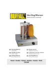
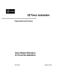
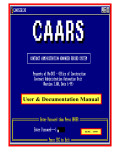
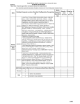
Perfect ACTM Module The Difference is in the Detail Troubleshooting Guide LGxxxA1C-B3 Product Specifications AC module DC Input Parameter Section Power Voltage Current Value Max. 295 W 300W 305W Tolerance 3% 3% 3% Open Circuit 39.7 V 39.8 V 40.0 V Max. Power Point 31.8 V 32.0 V 32.1 V Short Circuit 9.85 A 9.98 A 10.10 A Max. Power Point 9.28 A 9.40 A 9.52 A Relative Reduction Efficiency < 2.0% Note : *Relative efficiency reduction in respect to irradiance Note : Rated electrical characteristics are within 10 percent of above figures. PV module was measured at STC (Standard Test Condition : Irradiation 1,000W/m2, Cell temp. 77°F(25°C), 1,5AM) AC Output Parameter Section 240VAC 280W (@DC Module 295W) / 285W (@DC Module 300W) / 290W (@DC Module 305W) AC Continuous1) Power 208VAC Inverter Rated Continuous 305W 300W Rated 240V (211 ~ 264 V) 208V (187 ~ 229V) Rated 1.27A Voltage Current 1.44A Max. Fault Current 77A Nominal 60 Hz (59.3 ~ 60.5 Hz) Extended 57.0 Hz ~ 60.5 Hz Efficiency Power Factor > 0.95 CEC Weighted Efficiency (California Energy Commission) 96.5% 96.0% Max. Number of AC Modules 12 ea 11ea 1) Pmax (AC) = Max. Input DC Power x CEC Efficiency Protection Ground Fault Detection and Interrupt (GFDI) Applied Fuse 2A CAUTION : FOR CONTINUED PROTECTION AGAINST THE RISK OF FIRE, REPLACE ONLY WITH SAME TYPE AND RATING OF FUSE Over Current Protection Device (OCPD) 2 20A AC module Mechanical Data Micro Inverter Model (Utility Interactive) LM305UE-G1 Enclosure Rating Type 6 Operating Ambient Temperature - 40 ~ 65 °C (-40 ~ 145°F) Operating Temperature (internal) - 40 ~ 90 °C (-40 ~ 194°F) Storage Temperature - 40 ~ 90 °C (-40 ~ 194°F) Weight 18.0 kg Certification UL 1703, IEC 61215 Ed 2, IEC 61730 Safety Class II, CE, ISO9001 UL1741 / IEEE1547 CSA 22.2 No. 107.1-01 FCC Part 15 Class B Dimension Unit: mm / in. Cross-sectional Drawings Short Side Frame Long side frame 3 Response to Abnormal Conditions IEEE 1547 (Default) Parameter Range Clearing Time (s) Phase Voltage V < 60V <0.16 60V ≤ V < 106V < 2.00 132 ≤ V < 144V < 1.00 V ≥ 144V < 0.16 (< 0.016, Hawaii mode - TOV)1) > 60.5Hz < 0.16 < 59.3Hz (< 57 Hz, Hawaii mode)1) < 0.16 Voltage Frequency Note 1 : This test is performed in nominal conditions, except for test parameter Note 2 : After clearing, if grid returns to the normal state, it takes up to 5 minutes for operation of AC module Dedicated Cables Trunk Cable Connector Type TC-ER sunlight resistant Max. Voltage 600V Max. Current 20A Size 12AWG Max. Voltage 300V Max. Current 20A Drop Cable Connector Type TC-ER sunlight resistant Max. Voltage 600V Max. Current 5A Size 18AWG Max. Voltage 300V Max. Current 5A Certification UL9703, UL6703A Dimensions 400 mm (95.75 inch) 53 mm (2.09 inch) 122 mm (4.80 inch) 4 31.5 mm (1.24 inch) 1,200 mm (47.24 inch) 66 mm (2.60 inch) Table of Contents Product Specifications 2 1 Safety 6 2 Messages and Alerts 1-1 APP Messages Notice #1 and #2 AC Voltage High/ Low Notice #3 AC Frequency Changing Too Fast Notice #4, #5 AC Frequency High/ Low Error #1 DC Voltage High Error #2 DC Current High Error #3 AC Current High Error #4 Inverter Failure Error #5 Temperature Protection Alert GFDI 8 9 11 11 12 12 13 13 14 14 3 Gateway and Communication Issues 3-1 Power Line Communication Issues 3-1-1 Factors that Affect Power Line Communication 3-1-2 Cautions during Gateway Installation 3-1-3 Problems Checking AC Module through the Smartphone App 3-1-4 Discrepancy of Installed AC Module Quantity on Smartphone App 3-1-5 Number of Registered AC Modules Fluctuating on Smartphone App 3-1-6 Checking for Interferences to the Power Line Communication 3-1-7 Connecting the Gateway to a Remote Router 3-1-8 Solving Connection Issues in the Gateway 3-1-9 Registering Additional AC Modules to the Gateway 3-1-10 Changing the EnerBox 3-1-11 Registering a Replacement AC Module to the Gateway 3-1-12 Relocating a Gateway with Completed AC Module Registration 15 15 16 16 16 16 17 18 18 19 19 20 20 4 Gateway and Communication Issues 4-1 Network Configuration Troubleshooting 21 5 1 Safety Note and comply with the safety guidelines of this manual while handling AC modules. Failure to comply may result in severe damage to the equipment and/or fatal injuries. 1-1 Safety Symbols Safety symbols are used to minimize loss and injury during handling and operation of the equipment specified in this manual. DANGER Failure to comply with the instructions may cause fatal injuries or immediate death. WARNING Failure to comply with the instructions may cause severe injuries or death. CAUTION Failure to comply with the instructions may cause injuries or damage to property. Failure to comply with the instructions may cause severe injuries or immediate death by overvoltage. Failure to comply with the instructions may cause injuries or damage to property by fire. AC Module DANGER • To prevent the risk of electric shock, stay away from current-carrying terminals during operation. And, allow several minutes after the circuit breaker has been turned off. It may be energized in the open position. • To prevent the risk of overvoltage, do not disconnect the cable connector during operation. WARNING • To prevent the risk of burns, do not touch metal parts during operation. • For safety, only qualified persons should service modules. • To prevent the risk of electric shock, stay away from damaged module(s). Do not use module(s) with broken glass or torn backsheets. • Damaged modules must be handled with proper safety equipment. Failure to comply may result in serious bodily injury or death. • For proper operation, make sure to use exclusively cables, connectors and accessories provided by LG Electronics. Parts that are not listed may cause critical danger. • For proper operation, the AC Module shall be connected only to a dedicated branch circuit. • To prevent the risk of fire, do not connect any device between the AC module and circuit breaker. Circuit breaker may not work properly. • Before installation, make sure to check that the area of location meets the required environment specified in Chapter 6. Product Specification (Voltage, frequency, temperature, number of AC modules, overcurrent device). CAUTION • Use proper equipment, connectors, wires and buttresses for the installation of the module. Failure to comply may result in product damage, product failure and/or bodily injury. • To reduce the risk of accidents, do not install during inclement weather. • To prevent the risk of electric shock, do not touch the glass surface or frame of the solar module after installation. • To prevent the risk of injury, do not apply pressure on the module (ex. placing heavy objects or stepping on the module). • To prevent the risk of injury, do not drop the module; modules must be gently handled and placed down. • For proper operation, do not scratch the coating surface of the frame. It may increase the corrosion of the frame. • For proper operation, do not concentrate sunlight on the module surface. • Addition of holes in the frame or glass of the module may decrease the strength and integrity of the frame or glass. • Do not remove warning labels. • Store the module in its original package until installation. 6 Gateway WARNING • EnerBox warranty void if cover removed. No serviceable parts inside. Refer servicing to qualified personnel. • To avoid communication interference, do not connect the product to power strips, surge protectors, or surge protector-embedded power strips. It is recommended to directly connect the gateway to a120VAC outlet. CAUTION • Only certified installers should enter the installer mode.PV system may malfunction. • Set the grid configuration to best suit the installation area. PV system may malfunction. 7 2 Messages and Alerts The app shows real time status of the AC modules under AC Module Status and System Status, as well as Array View and Events through the monitoring web server. Please refer AC module System Installation Instruction and AC Module Web Server Manual for further details. Ex) App Messages Screen 1 2 3 1 Date 2 AC module ID 3 Message type Ex) Web Array View Screen 1 2 3 4 Select monitoring levels. (ex. Full System, by Gateway or individual AC Module) Set the monitoring period. (Today, Past 7 Days, Month, etc.) Installer scan zoom in or out of the screen. If the module is red, maintenance is required. Click the red module to see more details. 5 Installer can check today’s production information in this area. (System Energy, Peak Power and Latest Power) 8 Ex) Web Event Screen 1 Current Issues : Provides the current conditions of the system. 2 Event History : Provides the event records for aspecified period. 3 Click the device in the query results to check the “Issue Details”. A pop-up window will appear. Issue Details : Shows the following information: Affected devices, alert type, alert duration and detailed descriptions. Notice #1 and #2 AC Voltage High/ Low • It occurs when the system voltage is lower or higher than the operational threshold. Due to a problem of the power company, it can temporarily happen or and it is automatically adjusted by the power company. If the problem persists, check the followings. Nominal Voltage 240 Volt AC Nominal Voltage 208 Volt AC L1, L2 to neutral 106 to 132 Vac L1, L2, L3 to neutral 106 to 132 Vac L1 to L2 211 to 264 Vac L1 to L2 to L3 183 to 229 Vac Ex) Voltage Low Screen App Message Screen Web Event Screen • Check the voltage at terminals in the distribution panel,sub-panel, AC junctionbox and transformer between the grid and the AC module system. Otherwise, the grid may be unstable or there may be a problem with the maximum capacity of the transformer. There is also a possibility of short circuits arising between two conductors. 9 The below diagram illustrates an example of checking the voltages. Voltage Measurement 0000 0 2-pole 20A 2-pole (Determined according to the total current) G N L1L2 X12 [An array of AC modules] [AC junction box] [Distribution panel] • Check the wirings to see if the connection is ok. The conductors in the cables may have been damaged or cut. • Check if the connector connection is ok. The connector may be broken or connected improperly. • Check that there is not discrepancy between the real grid voltage and the voltage setting in the installation app. • Check that the permissible current of the circuit breaker is 20A. • Check if the cables are for outdoor usage. • Check the size of the cables. If the size of the cables is smaller than 12AWG, the flowing current in cables may be limited and the voltage may rise. 10 Notice #3 AC Frequency Changing Too Fast • Occurs if system voltage is lower or higher than the operational threshold. It is usually caused by a problem with the energy company. It may be a temporary problem, and is automatically corrected by the energy company. If the problem persists, check the following: Ex) Frequency Changing Too Fast Screen App Message Screen Web Event Screen • Check if there other any other alerts from the app. • Check the system voltage. • Inquire to the power company after closing the circuit breaker. Notice #4, #5 AC Frequency High/ Low • Occurs if system voltage is lower or higher than the operational threshold. It is usually caused by a problem with the energy company. It may be a temporary problem, and is automatically corrected by the energy company. If the problem persists, check the following: Nominal Frequency 60Hz 59.3 to 60.5Hz Hawaii 57 to 60.5Hz Ex) AC Frequency Low App Message Screen Web Event Screen • If you receive a message regarding low AC Voltage, please check the circuit breaker. • Problem may occur due to instability of the utility service. 11 Error #1 DC Voltage High • Occurs if the AC module DC input voltage is higher than 50V. DC Voltage Operation Range 20 to 45 VDC Ex) DC Voltage High Screen App Message Screen Web Event Screen • Check for possible damages in the module and microinverter. • If problem persists, request for a replacement AC module. Error #2 DC Current High • Occurs if the AC module input current is higher than the limit. Max. Input Operating DC current 12 ADC Ex) DC Current High Screen App Message Screen Web Event Screen • Using a multimeter, check the voltage of the input terminal. • Check for other messages. • If problem persists, request for a replacement micro inverter. 12 Error #3 AC Current High • Occurs if the AC module output current exceeds the operational threshold. Nominal Voltage 240 Volt AC Max. Output AC current Nominal Voltage 208 Volt AC 1.27A AC Max. Output AC current 1.44A AC Ex) AC Current High Screen App Message Screen Web Event Screen • Check for other messages. • Problem may stem from instability of the utility service. • Check that proper cables are used for the system and that the AC connector is connected correctly. Error #4 Inverter Failure • Occurs if AC module malfunctions.. Ex) Inverter Failure Screen App Message Screen Web Event Screen • Check for other messages. • Problem may stem from instability of the system. • Check that proper cables are used for the system and that the AC connector is connected correctly. 13 Error #5 Temperature Protection • Occurs if the internal temperature of the inverter is outside of the operation range; operation will automatically be stopped. Operating Temperature (Internal) -40 ~ + 90°C (-40 ~ +194°F) Ex) Temperature Protection Screen App Message Screen Web Event Screen • Check that the operational ambient temperature is within the operational range. If the ambient temperature is above 65°C (145°F), the internal temperature of the micro inverter may exceed 90°C (194°F). • Operation will resume automatically when the ambient temperature returns within the operational range. Alert GFDI • Occurs if the system current leakage exceeds the limit. Ex) GFDI Screen App Message Screen Web Event Screen • Check for other error messages. In case of a GFDI error, the system will automatically reset within 1 minute. • If problem persists, check all connections. Check that the wirings status is ok. The insulators (or jackets) of the cables may be worn out or cut. What is GFDI(Ground Fault Detector/Interrupter)? Ground fault is when currents flowing through the cable leak through an exposed conductor and touches the ground. The GFDI(Ground Fault Detector/Interrupter) function detects events of ground fault and automatically stops operation of the AC module. 14 3 Gateway and Communication Issues 3-1 Power Line Communication Issues • The micro inverter has a built-in power line communication module to support communication with the gateway. The gateway includes the same module to communicate with the microinverter. LG AC module monitoring system is designed to automatically achieve power line communication without additional configuration. However, the gateway and microinverter are commonly connected to the same power source in a home or building. As a result, other devices can affect the communication between the gateway and micro inverter, and vice versa. This interference can lead to communication issues. 1. AC Module Power Communication Distribution board Smartphone (Installation App) 2. C ommunication Gateway Meter Server Router 3. M onitoring PC Gird Smartphone 3-1-1 Factors that Affect Power Line Communication • Power strips or surge protectors in the same circuit. • UPS (Uninterruptible Power Supply) or Battery backup units in the same circuit. • Lamp dimming switches. • Power line communication-based home networks or home automation devices. • Sensor lamps • Battery Chargers (Cell phone and laptop charger) • AC Adapters • Heavy rotating motors (fans, refrigerators, freezers, water pumps, etc.) • Home Appliances including but not limited to washing machines and dryers, vacuums, hair dryers, electric drills, etc. • Electricity powered insect repellants. • Other electronic devices. - Please designate a power outlet for the sole use of the gateway. 15 3-1-2 Cautions during Gateway Installation • Power strips, surge protectors and outlet adapters can interfere with power line communication. Be sure to plug the gateway directly to a power outlet. • A lamp or light switch can contribute unwanted noise to the communication. Be sure to dedicate a power outlet for the sole use of the gateway. • Existing home appliances and other electronics can interfere with the gateway’s power line communication. 3-1-3 Problems Checking AC Module through the Smartphone App • If AC modules registered to a gateway cannot be accessed through the smart phone app, there is a communication problem between the gateway and AC module. • This could be a problem with the current outlet. Try to connect the gateway to a different outlet. • Though the maximum communication distance range is 328 yds. (under optimal conditions), it is recommended to install the gateway within 109 yds. (100m) of the AC modules. • It is strongly recommended to have a dedicated outlet between the gateway and AC module. Appliances and devices using the same outlet will disrupt communication. 3-1-4 D iscrepancy of Installed AC Module Quantity on Smart phone App • If the number of AC module on the app does not correctly reflect the number of installed modules, it is a possibility that the AC modules are not fully operational due to insufficient power supply for communication. After checking that energy is being generated in the modules, try scanning for the missing modules on the app. • Scan for the AC modules during the day when they are generating energy. • If the error continues, there is a problem with the communication connection. Please refer to 3-1-1 Factors that Affect Power Line Communication. 3-1-5 Number of Registered AC Modules Fluctuating on Smart phone App • The number of registered AC modules can change on the app for two reasons. • The built-in power line communication module is powered through the micro inverter. Depending on the level of solar power generation, the communication module might not receive sufficient power to communicate normally with the gateway. Refresh the app during a different time. • Communication errors can arise from the use of certain household devices. Please try again after powering off the devices suspected of causing the problem.If the error persists, please refer to 3-1-1 Factors that Affect Power Line Communication. 16 3-1-6 Checking for Interferences to the Power Line Communication • If there is still a problem with the connection between the gateway and the AC module, it is necessary to check the factors causing interference. • First, connect the gateway directly to the AC module. This will eliminate any potential interference caused by other devices; normal communication should be achieved and the AC modules should be detectable by the smart phone app. If the AC modules are still not detected on the app, there could be a communication problem between the smart phone/tablet and the gateway. If you suspect that there is a problem with the gateway, please request for a replacement unit. It is recommended to install the gateway as illustrated in the figure below to prevent communication interferences. PV Rack AC Module Trunk Cable Transition Cable AC Junction Box Equipment Grounding Conductor General AC Cable Communication Gateway Meter 0000 0 Sub Panel Installation App G N L1L2 120VAC Distribution Panel • If normal communication between the gateway and the AC module is established, close all the circuit breakers except for that of the gateway and the AC module. Disconnect the gateway from the AC module and re-install it indoors. • Verify that the connection between the gateway and AC module is maintained after the second installation. The correct number of AC modules should now be visible from the app. • Turn on one of the circuit breakers and wait 10 to 15 minutes. Scan for the AC modules through the app. If successful, turn on another circuit breaker and scan for the AC modules. Repeat until all circuit breakers are back on. If you encounter an error while scanning, the last circuit breaker is interfering with the communication. 17 3-1-7 Connecting the Gateway to a Remote Router If the gateway cannot detect the installed AC modules, it is recommended to move the gateway near the distribution panel for more reliable communication. To do so, the gateway needs to be connected to a remote router via PLC Bridge as illustrated below. 4 Power Line Adapter PLC Bridge Broadband router Server Power Line Adapter 1 2 3 1 Connect the AC adapter from Power Port (12V/1A) of the gateway to a dedicated 120VAC outlet. 2 Connect the PLC cable from PLC IN Port of the gateway to a dedicated 120VAC outlet. 3 Connect one of the power line adapters from the LAN Port of the gateway to a 120VAC outlet. 4 Connect the other power line adapter from a spare port on the broadband router to a 120VAC outlet. 3-1-8 Solving Connection Issues in the Gateway If connection problems occur on the gateway, please check the LED status located on the back of the gateway and follow the troubleshooting table below. If the problem persists, please turn off the system circuit breaker and contact the service center (1-888-865-3026, [email protected]) LED status Power LED(No Light) AC Adapter may be incorrectly connected. Check the AC Adapter and outlet in use; if power still does not come on, contact your electricity provider for possible power grid problems. GFDI ON (Red) Possible wiring problems within the system. Turn off then on using the system circuit breaker, and wait 10 minutes. PLC ON (Red) Connection between AC cable and outlet or system and power grid may be interrupted. Reconnect the AC cable; if light does not change to green, try other outlets. Wireless LAN ON (Red) 18 Troubleshooting Possible problem with the wireless module inside the gateway. Contact the service center. 3-1-9 Registering Additional AC Modules to the Gateway If you hit the Registration button before listing all AC modules, or you need to add the unlisted AC module, follow steps below. 1 E nter LGElectronics (initial password) on the blank box in figure and press EnerBoxGroupchage button toreturn the gateway to the initial condition. Check PLC LED. It should turn red. 2 Press the Back button. Wait for a minute and check that the PLC LED has changed green.Then, press MAC Address List and check if the additional AC modules have been listed. If you can’t check the additional AC modules, connect the gateway to another outlet near the distribution panel and search for the unlisted AC modules. 3 Press Registration button to finish. LGElectronics 3-1-10 Changing the EnerBox If the EnerBox is not working correctly, follow steps below to troubleshoot. 1 After connecting a new EnerBox, enter the serial number of the failed EnerBox on the blank and press EnerBox Group change button. 2 Compare MAC addresses listed in App and web server. 3 If matching, press Registration button to finish. ex) 1121408000322 19 3-1-11 Registering a Replacement AC Module to the Gateway If you need toexchange an AC module, follow the steps below. 1 Enter LGElectronics (initial password) on the blank box in the figure and press the EnerBox Group chage button to return the gateway to the initial condition. Check that the PLC LED has turned red. 2 Press Back button. Wait for a minute and check that PLC LED is now turned to green. Then. press MAC Address List and check if the additional AC modules have been listed. If you can’t see the additional AC modules, connect the gateway to another outlet near the distribution panel and search for the unlisted AC modules. 3 Press Delete button to delete the exchanging AC module MAC address. 4 Press Registration button to finish. LGElectronics 3-1-12 Relocating a Gateway with Completed AC Module Registration After the EnerBox is connected to a 120VAC outlet of the new location, enter into AC Module Status and check that all previously registered MAC addresses colors are shown in black. MAC address color is red : Unreliable link detection. If some MAC addresses colors are red, the EnerBox must be connected to a different AC outlet. 20 4 Gateway and Communication Issues 4-1 Network Configuration Troubleshooting Web Server Communication Errors • Check the LAN cable connection to the wired LAN port. If necessary, reconnect. • Check the hub or router settings. • Check the smart phone app settings. • Check that the server IP and domain are listed correctly on the app. • Reset the power of the Gateway. • Check that the network is stable with your service provider. 21 Memo 22 Memo 23 This document is subject to change without notice. LG, LG logo and Life's Good are trademarks of LG Electronics, Inc. worldwide. Trademarks and intellectual properties of LG Electronics, Inc. are protected by international copyright laws.