1
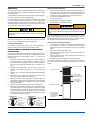
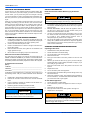
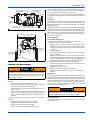
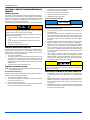
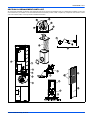
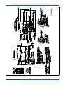
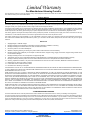
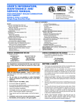
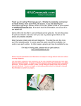
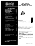
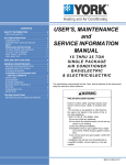
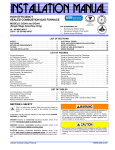
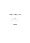
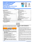
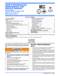
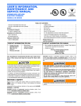
USER’S INFORMATION, MAINTENANCE AND SERVICE MANUAL HIGH EFFICIENCY SEALED COMBUSTION GAS FURNACE For Installation In: 1. 2. 3. MODELS: DGAA and DGAH (Single Stage Downflow Only) Manufactured (Mobile) Homes Recreational Vehicles & Park Models Modular Homes & Buildings TABLE OF CONTENTS CONTACT INFORMATION FOR USA . . . . . . . . . . . . . . . . . . . . . . . 1 CONTACT INFORMATION FOR CANADA . . . . . . . . . . . . . . . . . . . 1 SAFETY . . . . . . . . . . . . . . . . . . . . . . . . . . . . . . . . . . . . . . . . . . . . . . . . 1 While you are away . . . . . . . . . . . . . . . . . . . . . . . . . . . . . . . . . . . . 2 SEASONAL SERVICE INFORMATION . . . . . . . . . . . . . . . . . . . . . . 2 Your Service Technician . . . . . . . . . . . . . . . . . . . . . . . . . . . . . . . . 2 DESCRIPTION . . . . . . . . . . . . . . . . . . . . . . . . . . . . . . . . . . . . . . . . . 2 WARRANTY AND RESPONSIBILITIES . . . . . . . . . . . . . . . . . . . . . 2 GAS SUPPLY . . . . . . . . . . . . . . . . . . . . . . . . . . . . . . . . . . . . . . . . . . 3 Natural Gas Operation . . . . . . . . . . . . . . . . . . . . . . . . . . . . . . . . . . 3 Propane Gas Operation . . . . . . . . . . . . . . . . . . . . . . . . . . . . . . . . . 3 INSTRUCTIONS FOR EXAMINING THE FURNACE INSTALLATION . . . . . . . . . . . . . . . . . . . . . . . . . . . . . . . 3 Observing Burner Operation . . . . . . . . . . . . . . . . . . . . . . . . . . . . . 3 If Furnace Fails to Operate Properly . . . . . . . . . . . . . . . . . . . . . . . 3 HOW YOUR GAS FURNACE WORKS . . . . . . . . . . . . . . . . . . . . . . 4 IF FURNACE FAILS TO OPERATE PROPERLY . . . . . . . . . . . . . . 4 When You Call For Service Assistance . . . . . . . . . . . . . . . . . . . . . 4 To Contact Your Serviceman . . . . . . . . . . . . . . . . . . . . . . . . . . . . . 4 SAFETY INFORMATION . . . . . . . . . . . . . . . . . . . . . . . . . . . . . . . . . 4 Read the Instructions Below Before Trying to Start the Furnace . . . . . . . . . . . . . . . . . . . . . . . . . . . . . . . . . . . . 4 START-UP AND SHUTDOWN INSTRUCTIONS . . . . . . . . . . . . . . . 4 Operating Instructions: . . . . . . . . . . . . . . . . . . . . . . . . . . . . . . . . . . 4 To Turn Off the Appliance: . . . . . . . . . . . . . . . . . . . . . . . . . . . . . . .4 FURNACE USER MAINTENANCE . . . . . . . . . . . . . . . . . . . . . . . . .5 Air Filters . . . . . . . . . . . . . . . . . . . . . . . . . . . . . . . . . . . . . . . . . . . .5 Removing Filters . . . . . . . . . . . . . . . . . . . . . . . . . . . . . . . . . . . . . .5 Blower Care . . . . . . . . . . . . . . . . . . . . . . . . . . . . . . . . . . . . . . . . . .5 Motor Lubrication . . . . . . . . . . . . . . . . . . . . . . . . . . . . . . . . . . . . . .5 SERVICE AND MAINTENANCE MANUAL . . . . . . . . . . . . . . . . . . . . .6 SAFETY SECTION . . . . . . . . . . . . . . . . . . . . . . . . . . . . . . . . . . . . . .6 FURNACE MAINTENANCE SECTION . . . . . . . . . . . . . . . . . . . . . .6 FURNACE CLEANING SECTION . . . . . . . . . . . . . . . . . . . . . . . . . .6 Burner Removal/Cleaning . . . . . . . . . . . . . . . . . . . . . . . . . . . . . . .6 Cleaning the Heat Exchanger . . . . . . . . . . . . . . . . . . . . . . . . . . . .6 THE FURNACE CONTROLS AND THEIR FUNCTION . . . . . . . . . .6 SEQUENCE OF OPERATION . . . . . . . . . . . . . . . . . . . . . . . . . . . . .7 Continuous Blower . . . . . . . . . . . . . . . . . . . . . . . . . . . . . . . . . . . . .7 Heating Cycle . . . . . . . . . . . . . . . . . . . . . . . . . . . . . . . . . . . . . . . . .7 Hot Surface Ignition System . . . . . . . . . . . . . . . . . . . . . . . . . . . . . .7 TROUBLESHOOTING . . . . . . . . . . . . . . . . . . . . . . . . . . . . . . . . . . .7 FURNACE CONTROL DIAGNOSTICS . . . . . . . . . . . . . . . . . . . . . .8 REPLACEMENT PARTS LIST . . . . . . . . . . . . . . . . . . . . . . . . . . . . . .9 WIRING DIAGRAM . . . . . . . . . . . . . . . . . . . . . . . . . . . . . . . . . . . . . .12 LIMITED WARRANTY . . . . . . . . . . . . . . . . . . . . . . . . . . . . . . . . . . . .14 CONTACT INFORMATION FOR USA CONTACT INFORMATION FOR CANADA • Contact us by mail: DISTRIBUTED BY: StyleCrest 801 W. 37th Street Building #7 Wichita, Ks 67219 • MANUFACTURED BY: York International 5005 York Drive Norman, OK 73069 The manufacturer recommends that the user read all sections of this manual and keep the manual for future reference. • SECTION I: SAFETY 1. The furnace area must be kept clear and free of combustible materials, gasoline and other flammable vapors and liquids. 2. Insulating materials may be combustible. The furnace must be kept free and clear of insulating materials. The furnace area must be examined when installed in an insulated space or when insulation is added to be sure that the insulation material has been kept away from the furnace. Follow the instructions exactly as shown on the OPERATING INSTRUCTION LABEL or the Start-up and Shutdown Instructions on Page 4 of this manual when lighting the furnace or turning the furnace off. Should the gas supply fail to shut off or if overheating occurs, shut off the gas valve to the furnace before shutting off the electrical supply. Do not use this furnace if any part has been under water. A flooddamaged furnace is extremely dangerous. Attempts to use the furnace can result in fire or explosion. A qualified service agency should be contacted to inspect the furnace and replace all gas controls, control system parts, electrical parts that have been wet or the furnace if deemed necessary. FIRE OR EXPLOSION HAZARD - Failure to follow safety warnings exactly could result in serious injury, death, or property damage. —Do not store or use gasoline or other flammable vapors and liquids in the vicinity of this or any other appliance. 3. —WHAT TO DO IF YOU SMELL GAS: • Do not try to light any appliance. • Do not touch any electrical switch; do not use any phone (including cell phone) in your building. • Leave the building immediately. • Immediately call your gas supplier from a neighbor’s phone. Follow the gas supplier’s instructions. • If you cannot reach your gas supplier, call the fire department. — Installation and service must be performed by a qualified installer, service agency or the gas supplier. Johnson Controls Unitary Products Go to website at www.york.com click on “contact”, then click on “contact form” and follow the instructions. Contact us by mail: York International Consumer Relations 5005 York Drive Norman, OK 73069 4. 5. 129099-BUM-J-0112 129099-BUM-J-0112 6. 7. 8. NEVER…Store flammable materials of any kind near your furnace. Gasoline, solvents, and other volatile liquids should be stored only in approved containers outside your home. These materials vaporize easily and are extremely dangerous. NEVER Store cleaning materials near your furnace. Materials such as bleaches, detergents, powdered cleansers, etc., can cause corrosion of the heat exchangers. Use the area around your furnace as a storage area for NEVER items which could block the normal flow of air. This flow of air is required for ventilation of the various furnace components. VENT PIPE FLUE COLLAR BLOWER MOTOR CAPACITOR … BLOWER BLOWER MOTOR COMBUSTION AIR PIPE PRESSURE SWITCH … SAFETY SHUTOFF SWITCH CONTROL BOARD BOOSTER DRAFT ASSEMBLY SILICONE TUBE FIRE OR EXPLOSION HAZARD GAS VALVE This furnace is designed and approved for use with Natural Gas and (LP) Propane Gas ONLY. DO NOT BURN ANY LIQUID FUEL OR SOLID FUEL IN THIS FURNACE. GAS BURNER ASSEMBLY Burning any unapproved fuel will result in damage to the furnace heat exchanger, which could result in Fire, Personal Injury, and/or Property Damage. AIR CONDITIONING COIL PANELS While you are away Your furnace is equipped with a safety device which will shut off the supply of gas to the burner in case of malfunction. For this reason it is never practical to assume that the furnace will operate unattended for a long period of time, especially if there is a possibility of damage to your property because of freezing. So, if you plan to be away from home, arrange for someone to check your house every day. SEASONAL SERVICE INFORMATION During extreme cold weather, ice may form on the furnace roof jack crown. Small amounts of ice forming on the roof jack will present no problem to proper furnace operation. However, excessive ice formation could restrict the combustion air supply to the burner causing inefficient burner operation. When the temperature is very cold, near zero or below, it is recommended that the roof jack be inspected every day or more frequently if required. If ice has started to collect on the roof jack crown, it should be carefully broken off. Your Service Technician Your furnace's best friend is your qualified service technician. If the unit gives any indication of improper operation, call your service technician. If the service technician is allowed to perform the normal routine care of your furnace, he can many times detect potential difficulties and make corrections before trouble develops. Preventative maintenance of this type will allow you to operate the unit with a minimum of concern, and at the same time will pay for itself in added years of comfort. DESCRIPTION This furnace shall be installed in the downflow position. Figure 1 shows a typical model in the downflow position. The furnace is equipped with an induced-draft vent blower and atmospheric burner. Combustion air is drawn through the roof jack and pushed into the burner box. Flue gas is forced from the heat exchanger by the vent blower and discharged through the flue pipe to the outside atmosphere. This is a forced air furnace. The furnace circulating air blower draws cool air from the house, passes it over the hot furnace heat exchanger and circulates the warmed air through the ductwork to the house. The furnace is equipped with the controls necessary for proper operation. The various components referred to in this manual and on the furnace rating plate are identified in Figure 1. 2 FIGURE 1: Component Locations WARRANTY AND RESPONSIBILITIES It is the sole responsibility of the home owner to make certain that the gas furnace has been correctly set up and converted to the proper fuel (Propane or Natural gas) and adjusted to operate properly. The manufacturer warrants the furnace to be free from defects in material or workmanship for the stated time in the warranty agreement (see warranty certificate packed with the furnace). However, the manufacturer will not be responsible for any repair costs to correct problems due to improper set-up, improper installation, furnace adjustments, improper operating procedure by the user, etc. It is also the sole responsibility of the home owner to make sure that the home if located above 2,000 ft. altitude be derated. Some specific examples of service calls which cannot be included in warranty payments are: 1. 2. 3. 4. 5. 6. 7. 8. 9. 10. 11. 12. 13. 14. Converting the furnace to use another type of fuel. Correcting faulty duct work in the home. Correcting wiring problems in the electrical circuit to the furnace. Resetting circuit breakers or other switches. Adjusting the burner air shutter or service calls made to correct problems caused by improper air adjustment. Correcting problems caused by improper gas supply pressure to the furnace. Instructional training on how to light and operate furnace. Furnace problems caused by installation of air conditioner, heat pump, or other air quality device. Problems caused by improper installation of the furnace flue assembly (roof jack). Adding a roof jack extension because of unusual wind conditions or snow conditions. Adjusting thermostats. Problems caused by construction debris which has fallen into the flue or combustion air openings. Replacement of fuses. Problems caused by plugged or restricted orifices by any means. You should establish a firm understanding of these responsibilities with your manufactured housing dealer, service company or gas supplier so there will be no misunderstanding at a later time. Johnson Controls Unitary Products 129099-BUM-J-0112 GAS SUPPLY Observing Burner Operation The gas supply to your home will either be Natural Gas or Propane gas. Your furnace will be factory equipped to operate on only one of these two different gases. 1. Observe burner to make sure it ignites. Observe color of flame. On natural gas the flame will burn blue with appreciably yellow tips. On Propane gas a yellow flame may be expected. If flame is not the proper color call a qualified service technician for service. 2. 3. 4. 5. Let furnace heat until blower cycles on. Turn thermostat down. Observe burner to make sure it shuts off. Let the furnace cool and blower cycle off. A small metal tag secured to the furnace next to the gas valve will specify the type of gas your furnace is equipped to use. If the gas is different from that specified on the metal tag, the furnace can be converted by following the instructions on the furnace safety label inside lower front panel. Parts for conversion are contained in the small bag attached to the gas valve. Be sure the proper size orifice is used, as specified on the furnace name plate. The furnace must be converted by a qualified technician. Improper conversion can cause unsafe operation, explosion, and/or fire or asphyxiation. Natural Gas Operation The furnace is designed for 7" W.C. inlet pressure. Pressure is reduced to 3 1/2" W.C. by the pressure regulator in the gas valve. Propane Gas Operation Should overheating occur, or the gas supply fail to shut off, shut off the manual gas valve to the furnace and allow blower to run until furnace cools down and blower shuts off before shutting off the electrical supply. If any abnormalities are observed when checking for correct operation, such as burner failing to ignite or to turn off, sooty flame, etc., call your nearest authorized service technician as shown in the Service Center List included in the home owner envelope with the furnace. If Furnace Fails to Operate Properly 1. Check setting of thermostat - and position of HEAT/COOL switch if air conditioning is installed. If a set-back type thermostat is employed be sure that the thermostat is in the correct operating mode. 2. 3. Check to see that electrical power is ON. Check to see that the knob or switch on the gas control valve is in the full ON position. Make sure filters are clean, return grilles are not obstructed, and supply registers are open. Be sure that furnace flue piping is open and unobstructed. Inlet pressure to the gas valve must be 11" W.C. When properly converted to Propane gas, the pressure is regulated at 10" W.C. INSTRUCTIONS FOR EXAMINING THE FURNACE INSTALLATION It is the owner’s responsibility to ensure that an annual inspection of the entire heating portion of the unit is made by a qualified service agency. Examine the furnace as outlined below in steps “1 - 6” before each heating season. 1. Examine the heat exchanger, through an access panel located on the supply air plenum. Visually examine the exterior sections of the vent/combustion air piping and the vent connectors to be sure that they are physically sound without holes or excessive corrosion. 2. Examine the vent pipe making sure it is firmly in place, and is physically sound without holes and all of the connections are secure. Examine return connections for Modular or Manufactured (Mobile) Homes. Examine the return air filter rack connections to make sure they are physically sound, sealed to the furnace door. Examine the furnace casing making sure the physical support is sound without sagging, cracks or gaps. Examine the furnace base making sure it is physically sound without cracks, gaps or sagging and has a good seal. Examine the furnace casing for obvious signs of deterioration. Examine the burner flames to make sure the burner look like they are operating properly. The burner flames for natural gas should appear blue with a few yellow tips. The burner flames for propane gas should appear blue with moderate yellow tips. The flame should appear cylindrical in shape and should extend from the end of the burner into the heat exchanger. 3. 4. 5. 6. 7. PROPANE GAS NATURAL GAS LIGHT BLUE WITH YELLOW TIPS WHITISH YELLOW TO LIGHT YELLOW DARK BLUE LIGHT BLUE BLUE TIPS JUST STARTING TO BECOME PRONOUNCED 4. 5. If the cause for the failure to operate is not obvious, do not attempt to service the furnace yourself. Call a qualified service agency or your gas supplier. 1. Examine Vent Pipe 2. Examine Filter Door 3. Remove Filter Door to Examine Combustion Air Pipe 7. Remove Burner Door to Examine Burner Flame 4. Examine Burner Door 5. Remove Burner Door to Examine Furnace Base and Air Conditioning Coil Panels FIGURE 3: Furnace Examination Checkpoints BLUE TIPS JUST STARTING TO BECOME PRONOUNCED FIGURE 2: Burner Flame Appearance Johnson Controls Unitary Products 3 129099-BUM-J-0112 HOW YOUR GAS FURNACE WORKS SAFETY INFORMATION Your furnace is a very easy appliance to take for granted. Season after season, it sits there in your home, keeping you warm and comfortable. For this reason, you may never have given much thought to the way your furnace operates. In order to get the safest and most efficient operation from your furnace, you should understand how your furnace does its job. Read the Instructions Below Before Trying to Start the Furnace When you set your thermostat to provide more heat in your home, you are starting the heating cycle of the furnace. First, the inducer motor starts to purge the heat exchanger of any remaining gases. Next, the hot surface ignitor glows and after a warm-up period the gas valve opens and ignition occurs. A short time later, the blower starts and distributes the warm air throughout the home. When the temperature setting on your thermostat is reached, the gas valve closes, the main burner is turned off, and the blower continues to run until the remaining warm air in the system is distributed. When the blower stops, the heating cycle has ended. If you do not follow these instructions exactly, a fire or explosion may result causing property damage, personal injury, and/or loss of life. 1. 2. 3. IF FURNACE FAILS TO OPERATE PROPERLY 1. 2. 3. 4. 5. Check setting of thermostat - and position of heat/cool switch if air conditioning is installed. If a set-back type thermostat is employed be sure that the thermostat is in the correct operating mode. Check to see that electrical power is “ON”. Check to see that the lever or switch on the gas control valve is in the full “ON” position. Make sure filters are clean, return grilles are not obstructed, and supply registers are open. Be sure that furnace flue piping is open and unobstructed. When You Call For Service Assistance Very often time can be saved if you will give the service agency the MODEL and SERIAL NUMBER of your furnace. This will enable him to determine the specific components used, and perhaps to better identify the possible problem and be better prepared if a service call is required. To Contact Your Serviceman (fill in) COMPANY: ______________________________________________ ADDRESS: ______________________________________________ TELPHONE: _____________________________________________ All appliances need maintenance by serviceman at the beginning of each heating season. Call your nearest authorized service technician to: 1. 2. 3. 4. 5. Replace filters. Clean all lint and dust from around furnace. Remove fan and clean all dust and lint from unit with stiff bristle brush. Inspect combustion chamber, the transition into the blower compartment, flue collar, and roof jack. Check the gas valve and line connections for leaks. Make any adjustments necessary for good operation. NOTICE The coil panel provides a good removable access for inspecting inside the furnace casing. Smoke or reflected light inside the casing indicates the presence of leaks in the heat exchanger. 4 4. This appliance does not have a pilot. It is equipped with an ignition device which automatically lights the burner. Do not try to light the burner by hand. BEFORE OPERATING; smell all around the appliance area for gas. Be sure to smell next to the floor because some gas is heavier than air and will settle on the floor. Use only your hand to push the gas control switch to the “on” position. Never use tools. If the switch will not operate by hand, don’t try to repair it, call a qualified service technician. Force or attempted repair may result in a fire or explosion. Do not use this appliance if any part has been under water. Immediately call a qualified service technician to inspect the appliance and to replace any part of the control system and any gas control, which has been under water. START-UP AND SHUTDOWN INSTRUCTIONS Operating Instructions: 1. 2. 3. 4. 5. STOP! Read the safety information above. Set the thermostat to the lowest setting. Turn off all electric power to the appliance. Remove furnace door. Move gas control switch to the “OFF” position. Do not force. See Figure 4. 6. Wait five (5) minutes to clear out any gas. If you then smell gas, STOP! Follow Step 2 (refer to Safety Information on Page 4). If you don’t smell gas, go to next step. 7. Move gas control switch to the “ON” position. Do not force. See Figure 4. 8. Replace burner door. 9. Turn on all electric power to the appliance. 10. Set thermostat to the desired setting. Burner will light, which may take 30-60 seconds. 11. After three (3) trials for ignition, if the appliance will not operate follow the instructions, “TO TURN OFF THE APPLIANCE” and call your service technician or gas supplier. To Turn Off the Appliance: 1. 2. 3. 4. 5. Set the thermostat to lowest setting. Turn off all electric power to the appliance if service is to be performed. Remove burner access panel. Move gas control switch to the “OFF” position. See Figure 4. Replace burner access panel. Should overheating occur, or the gas valve fail to shut off, turn the external manual gas valve in the gas supply line to the furnace to the “off” position and let the furnace cool off before shutting off the electrical power supply. Refer to Figure 5. Johnson Controls Unitary Products 129099-BUM-J-0112 MAIN REGULATOR ADJUSTMENT 90° FLANGE OUTLET (MANIFOLD) PRESSURE TAP INLET Do not operate the furnace, and call a certified dealer / servicing contractor to check and / or clean your furnace, or for more information if you have questions about the operation of your furnace. If all components appear to be in good operating condition, replace the front panels. Follow the operating instructions to place the furnace in operation. Air Filters SUPPLY PRESSURE TAP ELECTRICAL CONNECTIONS ON/OFF SWITCH (shown in OFF position) Dirty filters greatly restrict the flow of air and may cause damage to the moving parts of the furnace. If the filters become clogged the heat exchangers and blower motor could overheat resulting in a potentially dangerous situation. OUTLET FIGURE 4: Gas Valve The filters should be checked every 3 months (DO NOT USE PLEATED FILTER in this furnace). On new construction, check the filters every week for the first four weeks and every three weeks after that, especially if the indoor fan is running continuously. When replacing the filter(s) you must use filters that are the same size and type as those in the furnace (2 - 16 x 20 x1). Removing Filters Internally Mounted Air Filters The air filter is in a rack that is attached to the door of the furnace. To remove the filter you must do the following: GAS PIPE 1. GAS PIPE MANUAL SHUT-OFF VALVE GAS BURNER GAS VALVE DRIP LEG MANUAL SHUT-OFF VALVE DRIP LEG FIGURE 5: Gas Piping FURNACE USER MAINTENANCE Before proceeding, be sure the area is well ventilated. Turn the thermostat OFF. If the blower is running, wait until it stops automatically. Turn OFF the gas and electrical power supplies to the furnace. Check all metal parts and surfaces to be sure they have cooled to room temperature before you begin. Every time the filters are changed the following items should be visually inspected: • • • • Check roof jack assembly for blockage or leakage. Check all components to be sure they are in good condition and that there are no obvious signs of deterioration. Check the evaporator coil drain lines to make sure there are no cracks or leaks. Check for dirt or lint on any surfaces or on components. Do not try to clean any of the surfaces or components. Cleaning of the furnace and its components must be done by a qualified service professional. If, during the inspection of your furnace, you find any of the following conditions: • • • • Excessive amounts of dust and lint on components. Damaged or deteriorated components or surfaces. Leaks or blockage in the vent pipe passages. Water on any surface inside or outside of the furnace. Johnson Controls Unitary Products Before proceeding, be sure the area is well ventilated. Follow instruction “To turn off the appliance”. Check all metal parts and surfaces to be sure they have cooled to room temperature before you begin. 2. Remove the filter door. 3. Remove the air filter by sliding it down the track. The air filter will slide out of the rack. 4. Replace throw away filter(s)) with the same size new filter(s). Throw away filter(s)) may be replaced with cleanable filter(s) at this time. Cleanable filter(s) may be cleaned as described in the manufacturer instructions or as described in these instructions. To replace the filter after cleaning you must do the following: 1. 2. 3. 4. Slide filter into place. If the filter has been cleaned, make sure it is dry before re-installing it. Replace the door or cover panel. Make sure the door snaps into the retaining clips. Follow the Operating Instructions to place the furnace back in operation. Blower Care Even with good filters properly in place, blower wheels and motors will become dust laden after long months of operation. The entire blower assembly should be inspected annually. If the motor and wheel are heavily coated with dust, they can be brushed and cleaned with a vacuum cleaner. If the blower cannot be properly cleaned without removing it from the furnace, then call a qualified service agency. Only a qualified service agency can perform this service. Make sure you DO NOT move the clip on weight on the indoor fan wheel when cleaning the wheel. This weight is used to balance the wheel. Moving the weight will cause the fan wheel to vibrate. Motor Lubrication The motors in these furnaces are permanently lubricated, and do not require periodic oiling. 5 129099-BUM-J-0112 SECTION II: SERVICE AND MAINTENANCE MANUAL SAFETY SECTION This section has been designed to assist a qualified service agency in performing service and maintenance on this appliance. The homeowners and/or end user must never attempt to perform any service or maintenance on the appliance especially when it involves the removal or adjustment of any parts and/or components. 5. 6. 7. 8. Remove the screws that hold the burner assembly to the combustion air box and remove the assembly. Remove burner from the burner assembly. Rinsing in hot water may clean burners. Reassemble in the reverse order. Cleaning the Heat Exchanger NOTICE The following safety rules must be followed when servicing the furnace. It is recommended that replacement gaskets be available before removing burner assembly and combustion air box. ELECTRIC SHOCK, FIRE OR EXPLOSION HAZARD Lower Heat Exchanger Access Failure to follow safety warnings exactly could result in dangerous operation, serious injury, death or property damage. 1. Improper servicing could result in dangerous operation, serious injury, and death or property damage. 2. • Before servicing, disconnect all electrical power to the furnace. • When servicing controls, label all wires prior to disconnecting. Reconnect wires correctly. 3. • Verify proper operation after servicing. 4. FURNACE MAINTENANCE SECTION The furnace should be cleaned and adjusted by a certified dealer or qualified service contractor once a year or before the start of every heating season. The following items must be cleaned and serviced or replaced if there are signs of deterioration. 1. The roof cap (if applicable). 2. The furnace vent pipe. Should it be necessary to service the vent/ air intake system, the manufacturer recommends this service be conducted by a qualified service agency. The operation of this appliance requires the reassembly and resealing of the vent/air intake system. 3. The furnace burner, ignitor and flame sensor. FURNACE CLEANING SECTION NOTE: The cleaning operations listed below must be performed only by a qualified service agency. Burner Removal/Cleaning The main burner should be checked periodically for dirt accumulation. If cleaning is required, follow this procedure: 1. 2. 3. 4. 6 Turn off the electrical power to the unit. Turn off the gas supply at the external manual shut-off valve and loosen the ground union joint. Remove the upper access panel. Disconnect wires from flame sensor, rollout switch and HSI igniter. Remove igniter carefully, as it is easily broken. 5. Turn off the electrical power to the unit and turn off gas supply at the shutoff valve. Remove the blower and burner compartment access doors. Disconnect the gas supply piping at the union to permit removal of the entire burner and gas control assembly from the vestibule panel. Use the wrench boss on the gas valve when removing or installing this piping. Unplug the igniter from the wire harness. Disconnect sensor wires. Identify and note the location of all leads for ease of reinstallation. Remove the screws holding the burner assembly to the vestibule panel and remove this assembly. Handle the assembly carefully since it contains the igniter, which is fragile and easily broken. The lower portion of the heat exchanger will now be exposed. Remove any soot and scale. Vacuum loose soot, scale and dirt from the heat exchanger. After cleaning is complete, replace all components in reverse order. Re-gasket all surfaces which required a gasket. Reconnect all wiring. Reattach vent pipe and gas supply lines before restoring service to furnace. Restore electrical power, check gas supply piping for leaks, and then verify furnace operation. Label all wires prior to disconnection when servicing controls. Wiring errors can cause improper and dangerous operation. Verify proper operation after servicing. THE FURNACE CONTROLS AND THEIR FUNCTION 1. 2. 3. Limit Control - This furnace is protected by two (2) high temperature limit switches. The lower limit switch is an automatic reset type. Upper Limit Control - The upper limit switch near left side of blower is a manual reset type limit switch. If burner does not function, turn system switch to “OFF” and push reset button in center of limit switch. Gas Valve - The gas valve is 100% shut-off type and will fail safe if for some reason the gas is turned off. It is also of the snap opening type which opens to fire position. Johnson Controls Unitary Products 129099-BUM-J-0112 SEQUENCE OF OPERATION TRANSFORMER NEUTRALS L1 HEAT On cooling/heating thermostats with fan switch, when the fan switch is set in the ON position, a circuit is completed between terminals R and G of the thermostat. The blower motor is energized through the cool fan terminal on the ignition control module. COOL LINE VOLTAGE BLACK - HIGH SPEED RED -LOW SPEED XFMR Continuous Blower Intermittent Blower - Cooling On cooling/heating thermostats with fan switch, when the fan switch is set in the auto position and the thermostat calls for cooling, a circuit is completed between the R, Y and G terminals. The motor is energized through the cool fan terminal and runs on the selected speed. The fan off setting is fixed at 60 seconds for SEER enhancement. FAN OFF JUMPER Heating Cycle When the system switch is set on HEAT and the fan is set on AUTO, and the room thermostat calls for heat, a circuit is completed between terminals R and W of the thermostat. When the proper amount of combustion air is being provided, a pressure switch activates the ignition control. The ignition control provides a 30-second warm-up period. The gas valve then opens for 10 seconds. If the flame is not detected within 2 seconds of the gas valve opening, the gas valve is shut off and a retry operation begins. If the flame is lost for 2 seconds during the 10 second stabilization period, the gas valve is shut off and a retry operation begins. During a retry operation the ventor starts a 15 second interpurge and the ignitor warm-up time is extended to 27 seconds. If the flame is established for more than 10 seconds after ignition, during a retry, the control will clear the ignition attempt (retry) counter. If three retries occur during a call for heat, the furnace will shut down for one hour. If at the end of the one hour shut down there is a call for heat, the furnace will initiate a normal start cycle. If the problem has not been corrected the furnace will again lockout after three retries. A momentary loss of gas supply, flame blowout, or a faulty flame probe circuit will result in a disruption in the flame and be sensed within 0.8 seconds. The gas valve will de-energize and the control will begin a recycle operation. A normal ignition sequence will begin after a 15 second inter-purge. If during the three recycles the gas supply does not return, or the fault condition is not corrected the ignition control will lockout for 60 minutes. During burner operation, a momentary loss of power for 50 milliseconds or longer will de-energize the gas valve. When the power is restored, the gas valve will remain de-energized and the ignition sequence will immediately restart. As the gas starts to flow and ignition occurs, the flame sensor begins its sensing function. If a flame is detected during the 10 second flame stabilization period the circulating blower will energize 30 seconds after the gas valve opens (20 seconds after the flame stabilization period ends). Normal furnace operation will continue until the thermostat circuit between R and W is opened. When the thermostat circuit opens, the ignition control is de-energized. When the ignition control is de-energized, the gas flow stops, and the burner flames are extinguished. The ventor continues to operate for 15 seconds after the gas flow stops. The blower motor continues to operate for the amount of time set by the fan-off delay "Jumper" located on the ignition control board. Refer to Figure 6. The heating cycle is complete, and the furnace is ready for the start of the next heating cycle. Johnson Controls Unitary Products FAN ON ADJUSTMENT JUMPER FUSE 3A FIGURE 6: Furnace Control Board Hot Surface Ignition System HOT SURFACE IGNITION SYSTEM Do not attempt to light this furnace by hand (with a match or any other means). There may be a potential shock hazard from the components of the hot surface ignition system. The furnace can only be lit automatically by its hot surface ignition system. TROUBLESHOOTING The following visual checks should be made before troubleshooting: 1. 2. 3. 4. Check to see that the power to the furnace and the ignition control module is ON. The manual shut-off valves in the gas line to the furnace must be open. Make sure all wiring connections are secure. Review the sequence of operation. Start the system by setting the thermostat above the room temperature. Observe the system’s response. Then use the troubleshooting section in this manual to check the system’s operation. Never bypass pressure switch to allow furnace operation. To do so will allow furnace to operate under potentially hazardous conditions. Do not try to repair controls. Replace defective controls with UPG Source 1 Parts. Never adjust pressure switch to allow furnace operation. 7 129099-BUM-J-0112 FURNACE CONTROL DIAGNOSTICS The furnace has built-in, self diagnostic capability. If a system problem occurs, a fault code is shown by a blinking green LED. It is located behind a clear view port in the blower compartment door. DO NOT turn off furnace power as this action will clear the control's memory of the fault. The control continuously monitors its own operation and the operation of the system. If a failure occurs, the LED will indicate the failure code. If the failure is internal to the control, the light will stay on continuously. In this case, the entire control should be replaced as the control is not field repairable. Flash sequence codes 1 through 6 are as follows: LED will turn “on” for one second and “off” for one second. This pattern will be repeated the number of times equal to the code. For example, six “on” flashes equals a number 6 fault code. 3 FLASH: Combustion air pressure switch failed to close, this indicates the normally open pressure switch contact did not close at the beginning of the heat cycle. This could be caused by a number of problems; faulty inducer, blocked vent pipe, broken pressure switch hose or faulty pressure switch. 4 FLASH: Limit Switch Open, this indicates that a primary or auxiliary limit switch has opened its normally closed contacts. With this fault code the control will operate the supply air blower and inducer. This condition may be caused by: dirty filter, improperly sized duct system, incorrect blower speed setting, incorrect firing rate or faulty blower motor. 5 FLASH: Gas flow with no call for heat. Check gas valve and gas valve wiring. RAPID FLASHES: Reverse Polarity, reverse polarity indicates reverse line voltage polarity. Both heating and cooling will be affected. Check polarity of both. STEADY ON: Normal Operation. All flash code sequences are broken by a 2 second “off” period. 60 MINUTE AUTOMATIC RESET FROM LOCKOUT: This control includes a "watchdog" type circuit that will reset from a lockout condition after 60 minutes. Operational faults 1, 3, 4 and Steady On will be reset. This provides protection to an unoccupied structure if a temporary condition exists causing a furnace malfunction. An example would be a low incoming gas supply pressure preventing unit operation. When the gas pressure is restored, at some point the "watchdog" would restart the unit and provide heat for the house. IGNITION CONTROL Normal flame sense current is approximately 3.7 microamps DC (a) Low flame signal control lockout point is 0.9 microamps DC (a) 1 FLASH: Ignition failure. 2 FLASH: Combustion air pressure switch closed, this indicates that the normally open pressure switch contacts are stuck in the closed position. The control confirms these contacts are open at the beginning of each heat cycle. This would indicate a faulty pressure switch or mis-wiring. NOTE: If a flame is detected the control flashes the LED for 1/8 of a second and then enters a flame stabilization period. Thermostat Satisfied Thermostat Calling for Heat (Seconds) 0 5 0 32 Fan on Delay 12 Seconds ON THERMOSTAT OFF OFF ON INDUCER OFF 15 Sec. Post Purge ON IGNITOR OFF OFF OFF OFF MAIN VALVE OFF CIRCULATING BLOWER OFF ON OFF OFF 60, 90, 120, 180 SEC. OFF Selectable Fan Off Delay FIGURE 7: Furnace Event Control Schedule 8 Johnson Controls Unitary Products 129099-BUM-J-0112 SECTION III: REPLACEMENT PARTS LIST All components, assemblies, accessories, and replacement parts for this furnace are available through your qualified service installer or refer to the service center list in your booklet. It is not recommended that the homeowner purchase, install, or replace any components of this furnace. Contact your local contactor, dealer, or service provider for additional information. 22 23 20 21 19 10 15 9 14 3 1 2 6 4 13 17 BURNER ORIFICE (SEE CHART) 16 7 5 6 18 12 11 CONTROL BOX DETAIL Johnson Controls Unitary Products 9 129099-BUM-J-0112 DGAA ITEM 1 2 3 4 5 6 7 8 9 10 11 12 13 DESCRIPTION DGAA056BDTB DGAA070BDTB DGAA077BDTB DGAA090BDTB Switch, Pressure Tubing Silicone (2’ Req’d) S1-32435972000 S1-02812499000 S1-02535358000 S1-37319801821 S1-03101932002 S1-02543267000 S1-07319801064 S1-32435972000 S1-02812499000 S1-02535358000 S1-37319801821 S1-03101932002 S1-02543267000 S1-07319801064 S1-32435972000 S1-02812499000 S1-02535358000 S1-37319801821 S1-03101932002 S1-02543267000 S1-07319801064 S1-32435972000 S1-02812499000 S1-02535358000 S1-37319801821 S1-03101932002 S1-02543267000 S1-07319801064 S1-37319804651 S1-02535354000 S1-7681-3301 S1-2940A3541 S1-02535380000 S1-37319801403 S1-37323792001 S1-02535354000 S1-7681-3301 S1-2940A3541 S1-02535380000 S1-37319801403 S1-37323792002 S1-02535354000 S1-7681-3301 S1-2940A3541 S1-02535381000 S1-37319801403 S1-37323792003 S1-02535354000 S1-7681-3301 S1-2940A3541 S1-02535381000 S1-37319801403 S1-02541021000 S1-1214-2511 S1-02541021000 S1-02541021000 S1-1214-2511 S1-1214-2511 Accessory (See Page 4) 7900-7611 7900-7611 S1-1468-220P S1-1468-220P S1-02435603000 S1-02435603000 S1-37319806100 S1-37319806100 S1-02521192000 S1-02521192000 S1-02420063000 S1-02420063000 S1-02435602000 S1-02435602000 S1-02435813000 S1-02435813000 S1-02619654003 S1-02619654003 S1-07319801342 S1-07319801342 155887 155887 S1-02118364000 S1-02118364000 S1-02118365000 S1-02118365000 S1-37323864001 S1-37323864001 S1-01006900005 S1-01006900005 S1-01006742000 S1-01006742000 S1-01006900015 S1-01006900015 S1-01006900001 S1-01006900001 S1-02541021000 S1-1214-2511 Limit Switch, Manual (Upper) Assembly, Booster (w/Motor) Control Board, Integrated Valve, Gas Bracket, Mounting (Gas Valve) 14 15 16 17 18 19 20 21 22 23 24* 25* 26* 27* 28* 29* 30* 31* 32* NOTE: Exchanger, Heat (w/Gaskets) Sensor, Flame Switch, System Transformer (115-24V, 40 VA) Switch, Limit Burner Assembly, Auto Ignition (Includes items 10 & 15) Ignitor, Hot Surface Filter (2 Req’d) (16x20x1) Panel, Door (Upper) Panel, Door (Lower, Tall) Motor (See Note 2) (old-see note 4) Motor (new-see note 4) Assembly, Motor Mount (See Note 2) Plug, Connector Capacitor, Run (See Note 3) (Old-see note 4) Capacitor (New-see note 4) Capacitor (Units built on/after 8/11/2008) Wheel, Blower Top, Casing Diagram, Wiring Strike, Door Latch, Door Housing, Blower Gasket, Combustion Air Box Gasket, Burner Gasket, Booster Assembly Gasket, Heat Exchanger 7900-7611 S1-1468-220P S1-02435603000 S1-37319806100 S1-02521192000 S1-02420063000 S1-02435602000 S1-02435813000 S1-02619654003 S1-07319801342 155887 S1-02118364000 S1-02118365000 S1-37323864001 S1-01006900005 S1-01006742000 S1-01006900015 S1-01006900001 < < 7900-7611 S1-1468-220P S1-02435603000 S1-37319806100 S1-02521192000 S1-02420063000 S1-02435602000 S1-02435813000 S1-02619654003 S1-07319801342 155887 S1-02118364000 S1-02118365000 S1-37323864001 S1-01006900005 S1-01006742000 S1-01006900015 S1-01006900001 *Not Shown New replacement parts shown in bold face type at the first printing of parts list dated 1/12. Major components and suggested stocking items are shown with shaded item number. “<“ Across from row indicates a change in that row. --- Not applicable to specified model. 2. For Serial Numbers lower then 001207164- Replacement DGAA motors also require Motor Mount Assembly 373-19806-100 if replaced motor has integral, flex-arm motor mount. 3. DGAA with 5-Ton Blowers are provided as an accessory item and are not standard equipment from the factory. See Page 4 4. The “old” motor must use the “old” run capcitor. The “new” motor can use either capacitor. Serial No. W0F6528688 and above were built with the new motor. 10 Johnson Controls Unitary Products 129099-BUM-J-0112 DGAH ITEM 1 2 3 4 5 6 7 8 9 10 11 12 13 14 15 16 17 18 19 20 21 22 23 24* 25* 26* 27* 28* 29* 30* 31* 32* DESCRIPTION DGAH056BBSB DGAH077BBSB Switch, Pressure Tubing Silicone (2’ Req’d) S1-32435972000 S1-02812499000 S1-02535358000 S1-37319801821 S1-03101932002 S1-02543267000 S1-07319801064 S1-32435972000 S1-02812499000 S1-02535358000 S1-37319801821 S1-03101932002 S1-02543267000 S1-07319801064 S1-37319804651 S1-02535354000 S1-7681-3301 S1-2940A3541 S1-02535380000 S1-37319801403 S1-37323792002 S1-02535354000 S1-7681-3301 S1-2940A3541 S1-02535381000 S1-37319801403 S1-02541021000 S1-1214-2511 S1-02541021000 S1-1214-2511 Limit Switch, Manual (Upper) Assembly, Booster (w/Motor) Control Board, Integrated Valve, Gas Bracket, Mounting (Gas Valve) Exchanger, Heat (w/Gaskets) Sensor, Flame Switch, System Transformer (115-24V, 40 VA) Switch, Limit Burner Assembly, Auto Ignition (Includes itemss 10 & 15) Ignitor, Hot Surface Filter (2 Req’d) (16x20x1) Panel, Door (Upper) Panel, Door (Lower, Short) Motor Assembly, Motor Mount Plug, Connector Capacitor, Run Wheel, Blower Top, Casing Diagram, Wiring Strike, Door Latch, Door Housing, Blower Gasket, Combustion Air Box Gasket, Burner Gasket, Booster Assembly Gasket, Heat Exchanger < < Accessory (See Page 4) 7900-7671 S1-02431948000 --S1-02521192000 --S1-02619654003 S1-07319801342 157953 S1-02118364000 S1-02118365000 S1-37323864001 S1-01006900005 S1-01006742000 S1-01006900015 S1-01006900001 7900-7671 S1-02431948000 --S1-02521192000 --S1-02619654003 S1-07319801342 157953 S1-02118364000 S1-02118365000 S1-37323864001 S1-01006900005 S1-01006742000 S1-01006900015 S1-01006900001 NOTE: *Not Shown New replacement parts shown in bold face type at the first printing of parts list dated 1/12. Major components and suggested stocking items are shown with shaded item number. “<“ Across from row indicates a change in that row. --- Not applicable to specified model. 3. DGAH with 5-Ton Blowers are provided as an accessory item and are not standard equipment from the factory. See page 4. BURNER ORIFICE CHART (Normal Altitude Only, See Note 5) MODEL 056 070 077 090 NATURAL GAS LP GAS S1-9951-1361 S1-9951-0821 S1-9951-1541 S1-9951-0931 S1-9951-1611 S1-9951-0981 S1-9951-1771 S1-9951-1061 ACCESSORY PARTS LIST ACCESSORY 5-Ton Blower Ass’y 7900-7751 DESCRIPTION Door Panel (Upper) Motor Run Capacitor (20 MFD) Motor Mount Blower Wheel DGAA DGAH 7900-7631 S1-02431975000 S1-02420051000 S1-37319802930 S1-1472-2761 7900-7631 S1-02431975000 S1-02420051000 S1-37319802930 S1-1472-2761 NOTES 5 Contact Customer Service for installations at altitudes over 2000 feet above sea level. “<“ Across from row indicates a change in that row. --- Not Applicable to specified model. Johnson Controls Unitary Products 11 129099-BUM-J-0112 SECTION IV: WIRING DIAGRAM FIGURE 8: Wiring Diagram - DGAA 12 Johnson Controls Unitary Products 129099-BUM-J-0112 FIGURE 9: Wiring Diagram - DGAH Johnson Controls Unitary Products 13 Limited Warranty For Manufactured Housing Furnace UPG warrants this product to be free from defects in factory workmanship and material under normal use and service and will replace parts that prove to have such defects according to the terms outlined below. FURNACE MODELS Furnace Model DGAA, DGAH Heat Exchanger Parts Coverage Labor and Trip Coverage* 10 years 2 years 1 years The warranty period for any replacement heat exchanger or part provided here under shall not extend beyond the warranty period stated above. The heat exchanger warranty is on a parts only basis: no labor, freight or other service charges are allowed. The warranty period will begin on the purchase date of the residence when the product is installed as original equipment, or the installation date when installed in a residence previously purchased by the consumer. Return the Warranty Registration Card to UPG promptly after product installation or purchase for your benefit and protection. The warranty period will begin upon product shipment from UPG in the absence of a recorded Warranty Registration Card. This warranty applies to the original consumer/purchaser and any subsequent purchaser. The warranty does not apply if the furnace is removed from the original residence, or if the residence has been moved from the original location where the furnace was placed in service. This warranty applies only to products installed: (1) in the United States of America or Canada; (2) in accordance with UPG recommendations and specifications outlined in the Installation Manual provided with the product; (3) in accordance with all national, state/provincial, and local codes; and (4) in the original residence. Exclusions 1. 2. 3. 4. 5. 6. 7. 8. 9. 10. 11. 12. 13. Shipping/freight, or material charges. Damages resulting from transportation, mishandling, improper application, installation or servicing. Damages resulting from accident, abuse, fire, flood, or other acts of nature. Use of the product in a corrosive atmosphere. Alteration, tampering, defacing or removing the product serial number will serve to void the warranty. Damages resulting from inadequacy or interruption of electrical service, improper energy supply, blown fuses, improper wiring external to the unit or other like damages. Damages resulting from the use of components not approved by UPG. This warranty does not cover consequential damages, incidental damages or incidental expenses including damages to property. Damages caused by failure to perform normal or routine maintenance as set out in the operation and service instructions. Cleaning, replacement of filters, or any other routine maintenance as set out in the User’s Information, Maintenance and Service Manual. Replacement or cleaning of nozzles or orifices. Fuses either internal or external to the product. Excessive fuel or electricity consumption. THIS WARRANTY IS IN LIEU OF ALL OTHER WARRANTIES, EXPRESSED OR IMPLIED, INCLUDING THE IMPLIED WARRANTIES OF MERCHANTABILITY AND FITNESS FOR A PARTICULAR PURPOSE. SOME STATES DO NOT ALLOW THE DISCLAIMER OF IMPLIED WARRANTY, SO THAT THE ABOVE DISCLAIMER MAY NOT APPLY TO YOU. SOME STATES ALLOW ONLY A PARTIAL LIMITATION ON IMPLIED WARRANTIES, OR LIMIT THE DURATION OF IMPLIED WARRANTIES TO THE DURATION OF THE EXPRESS WARRANTY. IN SUCH STATES, THE DURATION OF IMPLIED WARRANTIES IS HEREBY EXPRESSLY LIMITED TO THE DURATION OF THE EXPRESS WARRANTY ON THE FACE HEREOF. IN NO EVENT, WHETHER AS A RESULT OF BREACH OF WARRANTY OR CONTRACT TORT (INCLUDING NEGLIGENCE) STRICT LIABILITY OR OTHERWISE, SHALL UPG BE LIABLE FOR SPECIAL, INCIDENTAL, OR CONSEQUENTIAL DAMAGES, INCLUDING BUT NOT LIMITED TO LOSS OF USE OF THE EQUIPMENT OR ASSOCIATED EQUIPMENT, LOST REVENUES OR PROFITS, COST OF SUBSTITUTE EQUIPMENT. THIS WARRANTY DOES NOT COVER CONSEQUENTIAL DAMAGES. THE ABOVE LIMITATIONS SHALL INURE TO THE BENEFIT OF UPG SUPPLIERS AND SUBCONTRACTORS. THE ABOVE LIMITATION ON CONSEQUENTIAL DAMAGES SHALL NOT APPLY TO INJURIES TO PERSONS IN THE CASE OF CONSUMER GOODS. SOME STATES DO NOT ALLOW THE EXCLUSION OR LIMITATION OF LIABILITY FOR CONSEQUENTIAL OR INCIDENTAL DAMAGES, OR FOR STRICT LIABILITY IN TORT, SO THAT THE ABOVE EXCLUSIONS AND LIMITATIONS MAY NOT APPLY TO YOU. UPG DOES NOT ASSUME, OR AUTHORIZE ANY PERSON TO ASSUME FOR UPG ANY LIABILITY FOR THE SALE OF THIS PRODUCT. THIS WARRANTY GIVES YOU SPECIFIC LEGAL RIGHTS. YOU MAY ALSO HAVE OTHER RIGHTS WHICH VARY FROM STATE TO STATE. TO OBTAIN WARRANTY SERVICE Consult the Authorized Service Center list packed with the furnace installed in the manufactured home or contact your installing or servicing dealer. Or, look in the Yellow Pages of the telephone book under Mobile Homes-or Manufactured Housing-Repair and Service for the name and telephone number of the nearest authorized manufactured housing service center. If local authorized service cannot be obtained, or you are unable to contact your installing dealer, contact the authorized distributor in your area. If there is no distributor in your area, and you cannot obtain proper service under the terms of the warranty, please write: Unitary Products Group (UPG) Customer Relations Department, PO Box 19014, Wichita, KS 67204-9014. Subject to change without notice. Published in U.S.A. Copyright © 2012 by Johnson Controls, Inc. All rights reserved. Johnson Controls Unitary Products P.O. Box 19014 Wichita, KS 67204-9014 129099-BUM-J-0112 Supersedes: 129099-BUM-I-0711