1
Revised 12-98
$2.50
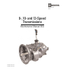
9-, 10- and 13-Speed
Transmissions
Maintenance Manual 26A
Design Level One
Design Level Two
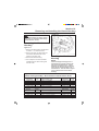
Service Notes
This Maintenance Manual describes the correct service and repair procedures for the nine-speed, ten-speed and
thirteen-speed Design Level One and Design Level Two manual transmissions.
You must follow your company safety procedures when you service or repair equipment. Be sure you understand all the
procedures and instructions before you begin work on the unit. Meritor uses the following types of notes to give warning
of possible safety problems and to give information that will prevent damage to equipment:
WARNING
A warning indicates procedures that must be followed exactly. Personal injury can occur if the
procedure is not followed.
CAUTION
A caution indicates procedures that must be followed exactly. If the procedure is not followed,
damage to equipment or components can occur. Personal injury can also occur in addition to damage
or malfunctioning of equipment or components.
TORQUE
This symbol is used to indicate fasteners that must be tightened to a specific tourque value.
NOTE
A note indicates an operation, procedure or instruction that is important for correct service. A note
can also give information that will make service easier and quicker.
Some procedures require the use of special tools for safe and correct service. Failure to use these special tools when
required, can cause injury to service personnel or damage to vehicle components.
Silicone Gasket Materials
WARNING
When you apply some silicone gasket materials, small amounts of acid vapor are present. To prevent
possible serious personal injury, make sure the work area is well-ventilated. If the silicone gasket
material gets into your eyes, flush them with water for 15 minutes. Have your eyes checked by a
doctor as soon as possible.
Loctite®
WARNING
Take care when using Loctite to avoid serious personal injury. Follow the manufacturer's instructions
to prevent irritation to the eyes and skin. If Loctite gets into your eyes, flush them with water for 15
minutes. Have your eyes checked by a doctor as soon as possible.
Cleaning Solvents
WARNING
If you use solvents, hot solution tanks or alkaline solutions incorrectly, serious personal injury can
occur. To prevent serious personal injury, follow the instructions supplied by the manufacturer of
these products. Do NOT use gasoline to clean parts. Gasoline can explode and cause serious
personal injury.
CAUTION
•
Use only solvent cleaners to clean ground or polished metal parts. Hot solution tanks or water
and alkaline solutions will damage these parts. You can use isopropyl alcohol, kerosene or diesel
fuel for this purpose.
•
If required, use a sharp knife to remove gasket material from parts. Take care not to damage
ground or polished surfaces.
Table of Contents
SUBJECT
PAGE
Section 1 - General Information ................................................................................... 5
Description .................................................................................................................... 5
Identification .................................................................................................................. 6
Nine-Speed Manual Transmissions .............................................................................. 6
Ten-Speed Manual Transmissions ............................................................................... 6
Thirteen-Speed Manual Transmissions ........................................................................ 6
Design Level 1 Manual Transmissions ......................................................................... 6
Design Level 2 Manual Transmissions ......................................................................... 8
Gear Timing .................................................................................................................. 9
Gasket Sealant ........................................................................................................... 12
Removing Gasket Sealant .......................................................................................... 12
Installing Gasket Sealant ............................................................................................ 12
Inspecting Used Parts ................................................................................................. 15
Repairing or Replacing Parts ...................................................................................... 19
Cleaning Ground or Polished Parts ............................................................................ 19
Cleaning Rough Parts ................................................................................................. 19
Drying the Cleaned Parts ............................................................................................ 19
Preventing Corrosion or Rust on Cleaned Parts ......................................................... 19
Section 2 - Lubrication and Maintenance.................................................................. 20
Transmission Oil Specifications .................................................................................. 20
Transmissions Oil Coolers .......................................................................................... 20
Scheduled Maintenance ............................................................................................. 21
Checking and Adjusting the Oil Level ......................................................................... 21
Checking the Condition of the Breather Vent ............................................................. 22
Checking Fastener Torque ......................................................................................... 22
Inspecting the Transmission for Leaks and Damage .................................................. 22
Draining and Replacing the Transmission Oil ............................................................. 23
Adjusting Remote Shift Housing Linkage ................................................................... 24
Lubricating the Remote Shift Housing ........................................................................ 24
Section 3 - In Vehicle Service ..................................................................................... 25
Removing the Shift Lever and Tower Assembly ......................................................... 25
Installing the Shift Lever and Tower Assembly ........................................................... 25
Removing the Slave Valve .......................................................................................... 27
Installing the Slave Valve ............................................................................................ 27
Removing the Air Filter and Regulator Assembly ....................................................... 28
Installing the Air Filter and Regulator Assembly ......................................................... 29
Removing the Output Yoke and Oil Seal .................................................................... 29
Installing the Oil Seal and Output Yoke ...................................................................... 30
Removing and Installing the Remote Control Assembly ............................................. 33
Page 1
8188C-TOC
1
2/1/99, 12:48 PM
Table of Contents (Continued)
SUBJECT
PAGE
Section 4 - Removing and Installing the Transmission .......................................... 34
Removing the Transmission ....................................................................................... 34
Installing the Transmission ......................................................................................... 36
Section 5 - Overhauling the Shift Lever and Tower Assembly ............................... 41
Disassembling the Aluminum Tower Assembly .......................................................... 41
Assembling the Aluminum Tower Assembly ............................................................... 43
Disassembling the Cast Iron Tower Assembly ........................................................... 46
Assembling the Cast Iron Tower Assembly ................................................................ 47
Section 6 - Remote Control Assembly ...................................................................... 48
Disassembling the Remote Control Assembly ............................................................ 48
Assembling the Remote Control Assembly ................................................................ 49
Section 7 - Removing and Installing the Top Cover Assembly............................... 50
Removing the Top Cover Assembly ........................................................................... 50
Installing the Top Cover Assembly ............................................................................. 52
Section 8 - Overhauling the Top Cover Assembly ................................................... 54
Disassembling the Standard and Forward Position Top Cover Assembly ................. 54
Assembling the Standard and Forward Position Top Cover Assembly ...................... 60
Disassembling the Standard and Forward Position “X” Bar
Top Cover Assembly ................................................................................................ 66
Assembling the Standard and Forward Position “X” Bar Top Cover Assembly .......... 72
Section 9 - Removing and Installing the Input Shaft................................................ 79
Removing the Input Shaft ........................................................................................... 79
Installing the Input Shaft ............................................................................................. 81
Section 10 - Removing and Installing the Clutch Housing ...................................... 83
Removing the Clutch Housing .................................................................................... 83
Installing the Clutch Housing ...................................................................................... 83
Section 11 - Removing and Installing the Auxiliary Case........................................ 85
Removing the Auxiliary Case-Nine-Speed and Ten-Speed Transmissions ............... 85
Installing the Auxiliary Case-Nine-Speed and Ten-Speed Transmissions ................. 90
Removing the Auxiliary Case-Thirteen-Speed Transmissions ................................... 94
Installing the Auxiliary Case-Thirteen-Speed Transmissions ..................................... 98
Removing the Auxiliary Drive Gear ........................................................................... 102
Installing the Auxiliary Drive Gear ............................................................................. 103
Section 12 - Overhauling the Main Case ................................................................. 104
Removing the Mainshaft ........................................................................................... 104
Removing the Input Shaft ......................................................................................... 110
Removing the Main Countershafts ........................................................................... 113
Page 2
8188C-TOC
2
2/1/99, 12:48 PM
Table of Contents (Continued)
SUBJECT
PAGE
Section 12 - Overhauling the Main Case(Continued) ............................................ 104
Removing the Reverse Idler Gear Assembly ............................................................ 114
Removing the Oil Pump ............................................................................................ 115
Removing the Magnets ............................................................................................. 116
Removing the PTO Covers ....................................................................................... 116
Installing the PTO Covers ......................................................................................... 117
Installing the Magnets ............................................................................................... 117
Installing the Oil Pump .............................................................................................. 118
Installing the Reverse Idler Gear Assemblies ........................................................... 118
Installing the Input Shaft ........................................................................................... 119
Installing the Main Countershafts ............................................................................. 123
Installing the Mainshaft ............................................................................................. 125
Section 13 - Overhauling the Auxiliary Drive Gear................................................. 134
Disassembling the Auxiliary Drive Gear Assembly ................................................... 134
Assembling the Auxiliary Drive Gear Assembly ........................................................ 136
Section 14 - Overhauling the Mainshaft .................................................................. 137
Disassembling the Mainshaft .................................................................................... 137
Assembling the Mainshaft ......................................................................................... 139
Section 15 - Overhauling the Main Countershafts ................................................. 150
Disassembling the Main Countershaft ...................................................................... 150
Assembling the Main Countershaft ........................................................................... 152
Section 16 - Overhauling the Auxiliary Case .......................................................... 155
Disassembling the Auxiliary Case-Nine-Speed and Ten-Speed Transmissions ...... 155
Assembling the Auxiliary Case-Nine-Speed and Ten-Speed Transmissions ........... 163
Disassembling the Auxiliary Case-Thirteen-Speed Transmissions .......................... 174
Assembling the Auxiliary Case-Thirteen-Speed Transmissions ............................... 182
Section 17 - Main Countershaft End Play Adjustment ........................................... 193
Checking and Adjusting the End Play of the Main Countershafts ............................ 193
Section 18 - Auxiliary Countershaft End Play Adjustment .................................... 200
Checking and Adjusting the End Play of the Auxiliary Countershafts ....................... 200
Section 19 - Troubleshooting ................................................................................... 207
General Information .................................................................................................. 207
Troubleshooting Other Systems ............................................................................... 208
Troubleshooting Leaks ............................................................................................. 209
Troubleshooting Vibrations ....................................................................................... 209
Troubleshooting Noises ............................................................................................ 210
Troubleshooting Operating Conditions ..................................................................... 211
Page 3
8188C-TOC
3
2/1/99, 12:48 PM
Table of Contents (Continued)
SUBJECT
PAGE
Section 20 - Specifications ....................................................................................... 214
Transmissions Oil Capacities ................................................................................... 214
Transmission Oil Specifications ................................................................................ 214
Fastener Torque Locations-Nine-Speed and Ten-Speed Transmissions ................. 215
Fastener Torque Chart-Nine-Speed and Ten-Speed Transmissions ....................... 218
Fastener Torque Locations-Thirteen-Speed Transmissions ..................................... 220
Fastener Torque Chart-Thirteen-Speed Transmissions ........................................... 223
Air Line Locations-Nine-Speed and Ten-Speed Transmissions ............................... 225
Air Line Identification Chart-Nine-Speed and Ten-Speed Transmissions ................ 226
Air Line Locations-Thirteen-Speed Transmissions ................................................... 227
Air Line Identification Chart-Thirteen-Speed Transmissions .................................... 228
Holding Cover Template ........................................................................................... 229
Special Tools ............................................................................................................ 230
Page 4
8188C-TOC
4
2/1/99, 12:48 PM
Section 1
General Information
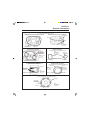
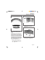
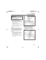
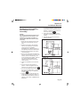
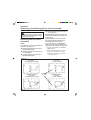
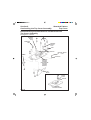
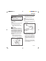
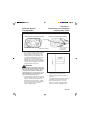
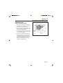
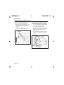
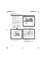
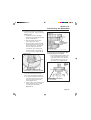
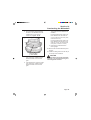
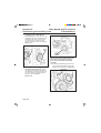
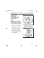
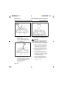
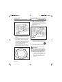
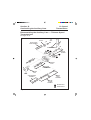
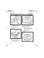
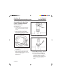
Description
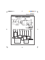
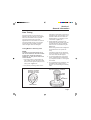
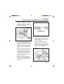
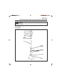
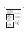
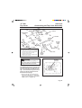
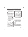
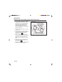
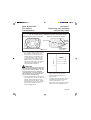
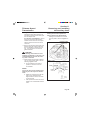
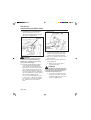
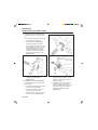
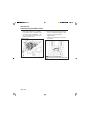
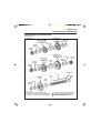
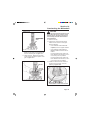
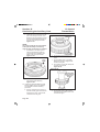
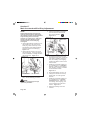
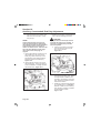
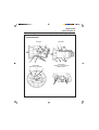
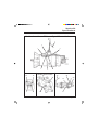
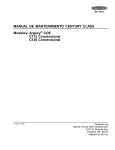
See Figure 1–1.
This publication describes the service
procedures for the following Meritor transmissions:
● Nine–Speed Transmissions.
● Ten–Speed Transmissions.
● Thirteen–Speed Transmissions.
Two design levels are described in this
publication:
● Design Level One. This applies to
transmissions with serial numbers
LB93001999 and below. Snap rings
are used to keep the tapered roller
bearings in the case.
● Design Level Two. This applies to
transmissions with serial numbers
LB93002000 and above. Retainer
plates are used to keep the tapered
roller bearings in the case.
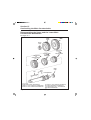
The main case, which includes the mainshaft, the main countershafts, the input
shaft, the reverse idler gear and the (optional) oil pump, are the same for all transmissions.
The auxiliary case is the same design for
nine-speed and ten-speed transmissions
while the auxiliary case for the thirteenspeed transmission is different. The thirteen-speed transmission uses a different
case, piston housing and output shaft
assembly. The thirteen–speed transmission also uses a splitter gear set in addition
to a HI and LO range gear set.
The input torque from the engine is distributed by two countershafts and one mainshaft. An auxiliary case provides the LO
and HI ranges of operation.
Tapered roller bearings are used to support the countershafts in the main transmission case and the auxiliary section.
Figure 1–1
NINE-SPEED TRANSMISSION
TEN-SPEED TRANSMISSION
THIRTEEN-SPEED TRANSMISSIONS
Page 5
Section 1
General Information
An air shift system is used to select the LO
or HI range of operation on all transmissions and the DIR and OD “splitter” range
of operation on thirteen-speed transmissions. For more information, see Maintenance Manual Number 26B, Nine Speed
Manual Transmissions Air Shift Systems or
Maintenance Manual 26D, Thirteen-Speed
Transmissions Air Shift Systems.
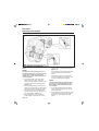
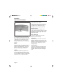
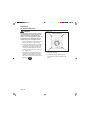
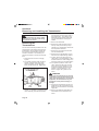
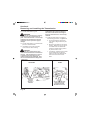
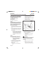
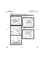
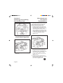
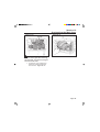
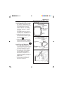
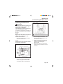
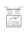
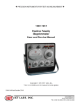
Identification
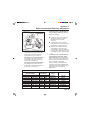
An identification plate is installed on the
side of the transmission. Use the information on the identification plate when ordering parts. Figure 1–2.
See Figure 1–2 for an explanation of the
model identification number and the identification plate.
Nine–Speed Manual
Transmissions
The transmission is identified by the number “9” in the Speed portion of the model
number. Figure 1–2.
The transmission uses nine forward gears
(five gears in the LO range and four gears
in the HI range) and two reverse gears.
The transmission may be either a “Design
Level 1” or a ”Design Level 2”. See the
explanation in this section.
Ten–Speed Manual
Transmissions
The transmission is identified by the number “10” in the Speed portion of the model
number. Figure 1–2.
The transmission uses ten forward gears
(five gears in the LO range and five gears
in the HI range) and two reverse gears.
The transmission is a ”Design Level 2”.
See the explanation in this section.
Thirteen–Speed Manual
Transmissions
The transmission is identified by the number “13” in the Speed portion of the model
number. Figure 1–2.
The transmission uses thirteen forward
gears (five gears in the LO range and
eight gears in the HI range that are divided
between four DIR gears and four O/D
gears) and two reverse gears.
The transmission may be either a “Design
Level 1” or a ”Design Level 2”.
The auxiliary case is different from the ninespeed and the ten-speed transmissions.
Design Level 1 Manual
Transmissions
Design Level 1 Manual Transmissions
apply to transmissions with serial numbers
below LB93002000.
The transmission is identified by the number “1” in the Design Level portion of the
model number. Figure 1–2.
Page 6
Section 1
General Information
Figure 1–2
RMX10-145A2S002
Meritor Transmission
Model Number
O.E.M. Transmission
Part Number
Manufacturing Date
Meritor Automotive
CUST#
MODEL
SERIAL NO. & ASS'Y PLANT
RATIO
DATE
Transmission
Serial Number
These Plugs
Indicate
Oil Pump
R M X 10-145 A 2 S 002
TYPE
A= Automated
E= Electric/Air
M=Manual
S= Engine
Synchro
Shift
W=Shift by
Wire
SPEED
Progressive
Forward
Speeds
RATIO
MERITOR
SHIFT PATTERN
No letter=direct drive
standard H pattern
X=overdrive
standard H pattern
O=overdrive 9-speed
non-standard pattern
OR
overdrive 13-speed
standard H pattern
x 10 =
Nominal
Input
Torque
SHIFT BAR
HOUSING
POSITION
F=Foward
S=Standard
SPECIFICATION
DESIGN LEVEL
1=Serial Numbers
LB93001999 and
Below
2=Serial Numbers
LB93002000 and
Above
Page 7
Section 1
General Information
Snap rings are used to retain the bearing
cups for the main countershaft in the main
case and for the auxiliary countershafts in
the auxiliary case and the main case.
Selective snap rings are used to adjust the
end play in the main case and the auxiliary
case.
Design Level 2 Manual
Transmissions
Design Level 2 Nine-Speed, Ten-speed
and Thirteen-Speed Manual Transmissions
apply to all transmissions with serial numbers LB93002000 and above.
Page 8
The transmission is identified by the
number “2” in the Design Level portion of
the model number. Figure 1–2.
Retainer plates are used to retain the
bearing cups for the main countershaft in
the main case. The bearing cover and the
selective washer are used to retain the
cups for the auxiliary countershaft in the
auxiliary case.
Selective shims are used to adjust the end
play in the main case. Selective washers
are used to adjust the end play in the
auxiliary case.
Section 1
General Information
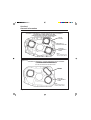
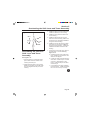
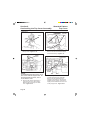
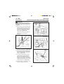
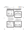
Gear Timing
If the timing marks on the gears are not
aligned in the main case or in the auxiliary
case, the transmission will not operate.
The timing marks must be correctly
aligned when the transmission is serviced.
The timing marks will not go out of alignment during normal vehicle operation
unless the gear teeth are damaged.
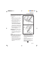
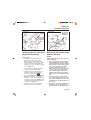
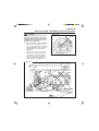
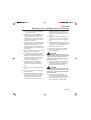
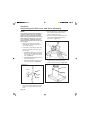
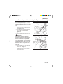
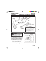
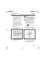
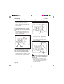
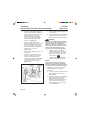
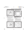
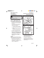
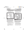
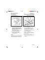
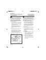
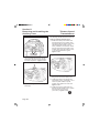
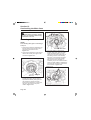
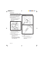
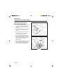
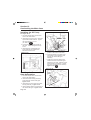
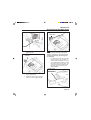
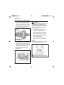
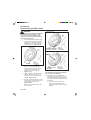
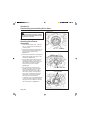
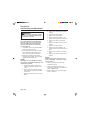
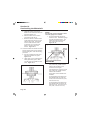
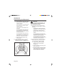
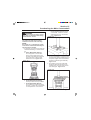
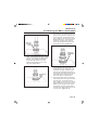
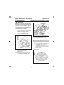
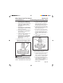
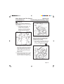
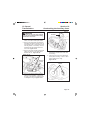
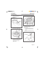
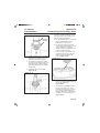
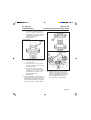
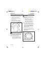
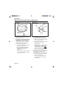
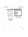
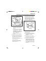
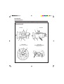
Timing Marks in Auxiliary Case
NOTE:
To make sure the timing marks are in
the correct locations, count the number
of gear teeth, divide the total teeth
number by “2” and put the mark in the
correct location.
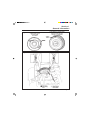
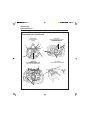
1. Put timing marks on the auxiliary low
gear. Mark one tooth with paint. Mark
a second tooth opposite (180o) the first
timing mark. Figure 1–3.
2. Use paint to put timing marks on two
Figure 1–3
teeth next to each other on each countershaft low gear of the auxiliary countershafts. Make sure the marks are
aligned with the “O” stamping on the
countershaft. Figure 1–3.
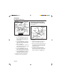
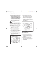
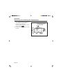
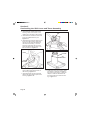
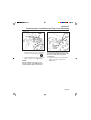
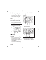
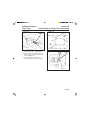
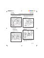
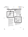
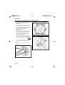
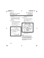
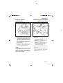
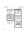
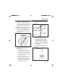
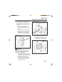
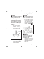
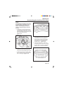
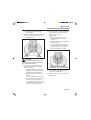
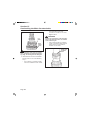
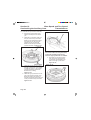
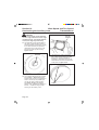
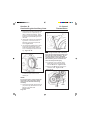
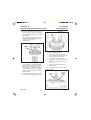
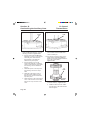
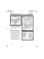
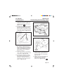
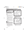
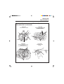
3. During assembly, each of the two
timing marks on the auxiliary low gear
must be between the two marked
teeth on each countershaft low gear.
Figure 1–4.
All the timing marks must be aligned if
the transmission is to operate correctly.
If the timing marks are not painted in
the correct position on the gears, only
one set of marks will be aligned.
4. To check the alignment of the timing
marks, rotate the output shaft seven
(7) complete revolutions. All the gears
must rotate.
5. For complete service procedures, see
‘Assembling the Auxiliary Case’ in
Section 16, “Overhauling the Auxiliary
Case”.
COUNTERSHAFT LOW GEAR-MARK
TWO TEETH OVER "O" STAMPING
AUXILIARY LOW GEARMARK ONE TOOTH ON
EACH SIDE 180° APART
TIMING
MARKs
"O"
STAMPING
TIMING MARKS
Page 9
Section 1
General Information
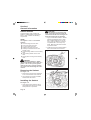
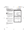
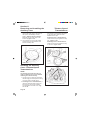
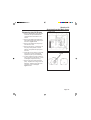
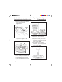
Figure 1–4
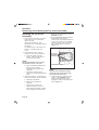
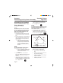
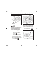
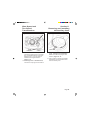
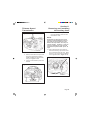
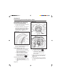
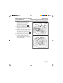
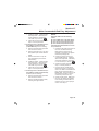
Timing Marks in Transmission
Case
NOTE:
To make sure the timing marks are in
the correct locations, count the number
of gear teeth, divide the total teeth
number by “2” and put the mark in the
correct location.
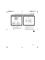
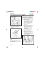
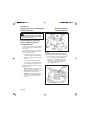
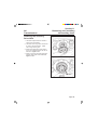
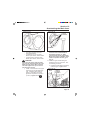
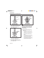
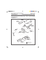
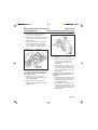
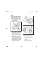
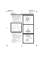
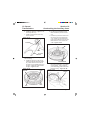
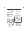
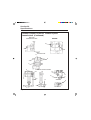
1. Put timing marks on the main drive
gear on the input shaft. Mark one
tooth with paint. Mark a second tooth
opposite (180o) the first timing mark.
Figure 1–5.
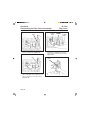
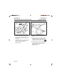
2. Use paint to put timing marks on two
teeth next to each other on each driven
gear of the main countershafts. Make
sure the marks are aligned with the
slot for the key or the “O” stamping on
the countershaft. Figure 1–5.
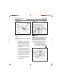
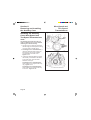
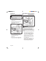
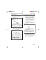
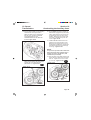
3. During assembly, each of the two
timing marks on the main drive gear
Page 10
must be between the two marked
teeth on each countershaft drive gear.
Figure 1–6
All the timing marks must be aligned if
the transmission is to operate correctly.
If the timing marks are not painted in
the correct position on the gears, only
one set of marks will be aligned.
NOTE:
The main shaft and the auxiliary drive
gear must be installed when the alignment marks in the transmission case
are checked.
4. To check the alignment of the timing
marks, rotate the input shaft. All the
gears must rotate.
5. For complete service procedures, see
‘Assembling the Transmission Case’ in
Section 12, “Overhauling the Main
Case”.
Section 1
General Information
Figure 1–5
COUNTERSHAFT DRIVEN GEAR
—MARK TWO TEETH OVER
THE SLOT FOR THE KEY
OR THE "O" STAMPING
MAINDRIVE GEAR
—MARK ONE TOOTH
ON EACH SIDE
180° APART
TIMING
MARK
TIMING
MARKS
Figure 1–6
Page 11
Section 1
General Information
Gasket Sealant
The transmission uses Loctite® RTV
Sealant™ #5699 (Meritor Part Number
2297-A-7021) between the following
components.
NOTE:
See Figures 1–9 to 1–11 for sealant
patterns.
Clutch housing and main case.
PTO covers and main case.
Top cover and main case.
Auxiliary case and main case.
Auxiliary countershaft covers and
auxiliary case.
● Output bearing retainer on the auxiliary
case.
● Input bearing retainer on the main
case.
● Range piston housing to the auxiliary
case.
●
●
●
●
●
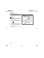
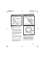
CAUTION
Apply the sealant in a 1/8 inch (2 mm)
bead. If too much sealant is used, the
sealant that extends over the edges can
break off and plug the oil passages.
2. Apply Loctite® RTV Sealant™ #5699
(Meritor Part Number 2297-A-7021)
with a sealant dispenser to one surface. Apply the sealant in a continuous pattern with a 1/8 inch (2 mm)
bead. Make sure the bead encircles
any fastener holes.
3. Install the component as described in
the correct section of this manual.
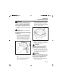
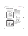
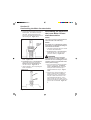
Figure 1–7
CAUTION
Use Loctite ® RTV Sealant™ #5699
(Meritor Part Number 2297-A-7021) as a
gasket. The use of any other gasket
material (such as a corrosive sealant)
can cause leaks and damage the transmission.
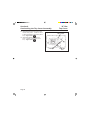
Removing the Sealant
See Figure 1–7.
1. Remove the component as described
in the correct section of this manual.
2. Use a scraper to remove all sealant
material from the surface.
Installing the Sealant
See Figure 1–8.
1. Clean the mounting surfaces with a
chlorinated solvent such as Loctite®
Safety Solvent or equivalent.
Page 12
Figure 1–8
SEALANT
DISPENSER
Section 1
General Information
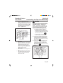
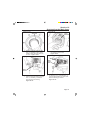
AUXILIARY COVER-TO-TRANSMISSION CASE GASKET PATTERN
Figure 1–9
• PUT THE PATTERN ON THE AUXILIARY COVER
TRANSMISSION CASE GASKET PATTERN
AUXILIARY COVER GASKET PATTERN
REAR COVER
BOLT HOLE
BEAD
NOTE:
APPLY SEALANT
IN A 1/8 INCH
(2MM) BEAD.
TRANSMISSION CASE
BOLT HOLE
CLUTCH HOUSING-TO-TRANSMISSION
CASE GASKET PATTERN
PTO COVERS-TO-TRANSMISSION CASE
GASKET PATTERN
• PUT THE PATTERN ON THE TRANSMISSION CASE
• PUT THE PATTERN ON THE TRANSMISSION CASE
MAKE SURE THE
PATTERN IS ON THE
TRANSMISSION
CASE AND NOT
ON THE RETAINER
NOTE:
APPLY SEALANT
IN A 1/8 INCH
(2MM) BEAD
PUT BEAD
AROUND HOLE
TRANSMISSION
CASE
NOTE:
APPLY SEALANT
IN A 1/8 INCH
(2MM) BEAD
BOLT
HOLE
SIDE COVER
BOTTOM COVER
NOTE: DO NOT BLOCK OIL FEED HOLE
SHIFT BAR HOUSING-TO-TRANSMISSION
CASE GASKET PATTERN
• PUT THE PATTERN ON THE TRANSMISSION CASE
OUTPUT BEARING RETAINER-TO-AUXILIARY
COVER GASKET PATTERN
• PUT THE PATTERN ON THE OUTPUT BEARING RETAINER
BOLT HOLE
OIL SLOT
BOLT HOLE
FOUR HOLES
SURROUNDED
BY SEALANT
NOTE:
APPLY SEALANT
IN A 1/8 INCH
(2MM) BEAD
TRANSMISSION CASE
NOTE:
APPLY SEALANT
IN A 1/8 INCH
(3MM) BEAD
BEAD TO BE
KEPT OUTSIDE
OF OIL SLOTS
OIL SLOT
RETAINER
INPUT BEARING RETAINER-TO-TRANSMISSION CASE GASKET PATTERN
• PUT THE PATTERN ON THE INPUT BEARING RETAINER
RETAINER
BEAD TO BE
KEPT OUTSIDE
OF OIL SLOTS
OIL SLOT
BOLT HOLE
NOTE:
APPLY SEALANT
IN A 1/8 INCH
(2MM) BEAD
Page 13
Section 1
General Information
Figure 1–10
AUXILIARY COUNTERSHAFT COVERS AND RANGE PISTON HOUSINGS
-TO-AUXILIARY COVER GASKET PATTERN
(NINE-SPEED AND TEN-SPEED TRANSMISSION)
• PUT THE PATTERN ON THE AUXILIARY COVER
PISTON
HOUSING
SURROUND ALL
HOLES WITH SEALANT
AUXILIARY
COUNTERSHAFT
COVER
NOTE:
APPLY SEALANT IN A
1/8 INCH (2MM) BEAD.
Figure 1–11
AUXILIARY COUNTERSHAFT COVERS AND RANGE PISTON HOUSINGS
-TO-AUXILIARY COVER GASKET PATTERN
(THIRTEEN-SPEED TRANSMISSION)
• PUT THE PATTERN ON THE AUXILIARY COVER
PISTON
HOUSING
AUXILIARY
COUNTERSHAFT
COVER
NOTE:
APPLY SEALANT IN A
1/8 INCH (2MM) BEAD.
Page 14
Section 1
General Information
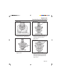
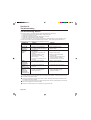
Inspecting the Parts
It is important to inspect all parts before the
transmission is assembled. Check all
parts for wear and replace damaged parts.
Replacement of damaged parts now, will
prevent failure of the assembly later.
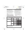
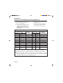
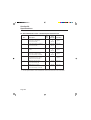
Tapered Roller Bearing Cone
NOTE:
The bearing cup and the bearing cone
must be replaced as an assembly except when the cup is loose in the bore.
If the cup is loose in the bore, install an
oversize cup. In all other situations, do
not replace the cup or the cone separately. Replace the cup and the cone in
a matched set from the same manufacturer. For replacement part numbers,
see the chart in Figure 1–12.
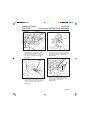
Inspect the cup, the cone , the rollers and
the cage of all tapered roller bearings. If
any of the following conditions exist, the
cup and the cone must be replaced.
1. The outer surface of the large diameter
end of the rollers is worn level with or
below the center. Figure 1–13.
2. The radius at the large diameter end of
the rollers is worn to a sharp edge.
Figure 1–13.
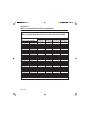
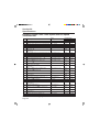
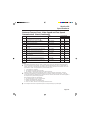
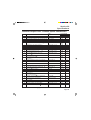
Figure 1–12
Tapered Roller Bearing Cup and Cone Replacement Chart
Component
Bearing
Cup
and Cone
Location
Transmission
Main Countershaft
Front
All
Rear
All
Front
9- and 10-Speed
Auxiliary Countershaft
13-Speed
Rear
9- and 10-Speed
13-Speed
Design
Level
Part Number
1
2
1
2
A-1228-W-1349
A-1228-T-1346 ➀
A-1228-V-1348
A-1228-S-1345 ➁
1
2
1
2
1
2
1
2
A-1228-X-1350 ➁
A-1228-S-1345 ➁
A-1228-U-1373
A-1228-S-1345 ➁
A-1228-Y-1373
A-1228-U-1347 ➂
A-1228-Y-1351
A-1228-U-1347 ➂
NOTES:
➀ Use Part Number XCD2139DT.
➁ Use Part Number XC11807DN.
➂ Use Part Number XC1837DF.
Page 15
Section 1
General Information
4. Deep cracks or breaks in the surface
of the cup, cone inner race or roller.
Figure 1–15.
Figure 1–13
RECESS
CENTER
WORN
LEVEL
Figure 1–15
SHARP
EDGE
3. A visible roller groove is worn in the
inner race surfaces of the cup or the
cone. The groove can be seen at the
small or large diameter end of both
parts. Figure 1–14.
Figure 1–14
5. Bright wear marks on the outer surface
of the roller cage. Figure 1–16.
6. Etching or pitting on rollers and on the
surfaces of the cup and cone inner
race that touch the rollers.
Figure 1–16.
Figure 1–16
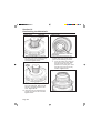
7. Spalling or flaking on the cup and cone
inner race surfaces that touch the
rollers. Figure 1–17.
Page 16
Section 1
General Information
Figure 1–17
Figure 1–18
NO SPALLS
2. Replace cups with small spalling or
flaking marks or light bruising.
Figure 1–19.
Figure 1–19
Tapered Roller Bearing Cups
NOTE:
The bearing cup and the bearing cone
must be replaced as an assembly except when the cup is loose in the bore.
If the cup is loose in the bore, install an
oversize cup. In all other situations, do
not replace the cup or the cone separately. Replace the cup and the cone in
a matched set from the same manufacturer. For replacement part numbers,
see the chart in Figure 1–12.
SMALL
SPALL
BRUISES
3. Replace cups with large spalls and
deep indentations. Figure 1–20.
1. Normal cup wear is shown as an
even wear across the surface of the
cup. Small indentations are acceptable. Figure 1–18.
Page 17
Section 1
General Information
Figure 1–20
O-Rings and Oil Seals
Inspect the O-rings and the oil seals for
cuts and cracks. Make sure the parts are
not brittle or hard. Replace any worn,
damaged or hard O-rings and oil seals.
Clutch Collars
LARGE SPALL
Inspect the teeth of the outside of the
clutch collar for wear and damage. Inspect
the splines inside the clutch collar for wear
and damage. Replace any worn or damaged clutch collars.
Case Housings
Ball Bearings
Inspect ball bearings for wear and damage. Make sure the bearings rotate in the
race. Make sure the outer race is not worn
or damaged. On bearings with grooves,
make sure the grooves are not worn or
damaged. Replace any worn or damaged
bearings.
Gears
Inspect the teeth of the gears for wear and
damage. Inspect the splines inside the
gears for wear and damage. Inspect the
gears for cracks or pits. Replace gears
that are worn, damaged or cracked.
Shafts
Inspect the splines and the grooves for
wear and damage. Make sure the shafts
are not twisted. Make sure threads on the
end of the shafts are not worn or damaged.
Replace any worn or damaged shafts.
Page 18
Inspect the case housings for cracks.
Replace cracked housings.
Top Cover
Inspect the tips of the forks for wear and
damage. Make sure the forks are not bent.
Make sure the shift rails are not worn or
damaged. Inspect the balls and springs for
wear or damage. Replace any worn or
damaged parts.
Output Yokes
Inspect the seal surface, the splines and
the end of the output yoke for wear and
damage. Do not sand or grind the seal
surface. Replace any worn or damaged
parts.
Section 1
General Information
Repairing or Replacing the
Parts
Replace worn or damaged parts. The
following are some examples to check.
1. Replace any fastener if the corners of
the head are worn.
2. Replace the washers if damaged.
3. Replace gaskets and oil seals at the
time of transmission repair.
4. Clean the parts and apply new gasket
material where required when the
transmission is assembled. See “Gasket Sealant” in this section.
5. Remove nicks, mars and burrs from
parts having machined or ground
surfaces. Use a fine file, india stone or
crocus cloth for this purpose (except
for yokes).
6. Clean and repair the threads of fasteners and holes. Use a die or tap of the
correct size or a fine file for this purpose.
CAUTION
Threads must be clean and undamaged
so that accurate adjustments and correct torque values can be applied to
fasteners and parts.
7. Use the correct type of Loctite ® or
equivalent and tighten all fasteners to
the correct torque values. See the
Torque Chart in Section 20, “Specifications”.
Cleaning the Ground or
Polished Parts
WARNING
If you use cleaning solvents, hot solution tanks or alkaline solutions incorrectly, injury can occur. To prevent
injury, follow the instructions supplied
by the manufacturer. Do NOT use gasoline to clean parts. Gasoline can explode.
Use a cleaning solvent to clean ground or
polished parts and surfaces. Kerosene or
diesel fuel can be used for this purpose.
DO NOT USE GASOLINE.
Do NOT clean ground or polished parts in
a hot solution tank or with water, steam or
alkaline solutions. These solutions will
cause corrosion of the parts.
Cleaning the Rough Parts
Rough parts can be cleaned with the
ground or polished parts. Rough parts
also can be cleaned in hot solution tanks
with a weak alkaline solution. Parts must
remain in the hot solution tanks until they
are completely cleaned and heated.
Drying the Cleaned Parts
must be dried immediately after cleaning.
Dry parts with clean paper, rags, or compressed air.
Preventing Corrosion and
Rust on Cleaned Parts
Apply lubricant to cleaned and dried parts
that are not damaged and are to be immediately assembled.
If parts are to be stored, apply a special
material that prevents corrosion and rust to
all surfaces. Store the parts inside special
paper or other material that prevents
corrosion and rust.
Page 19
Section 2
Lubrication and Maintenance
Transmission Oil
Specifications
CAUTION
Use only the specified type of single
weight oils. Do not use multi-viscosity
oils or EP (Extreme Pressure) gear oils.
Multi-viscosity oils and EP gear oils
may damage components. The use of
multi-viscosity or EP gear oils voids the
warranty.
Transmission Oil Coolers
Use a transmission oil cooler for any of the
following.
●
The transmission operating temperature is always more than 225oF (107oC)
at continuous operation or 275oF
(135oC) at intermittent operation.
●
The engine has a horsepower rating of
399 HP or more. Some aerodynamic
vehicles with less than 399 HP may
require a cooler due to the lack of air
which flows over the transmission to
dissipate heat.
Use the specified type of single weight oil
when adding or replacing oil. Use the
correct type of oil for the outside temperature. Engine oil, mineral oil and full-synthetic lubricants are recommended. DO
NOT MIX OILS.
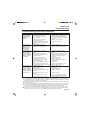
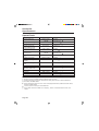
See the chart in Figure 2–1 for oil specifications.
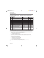
Figure 2–1
LUBRICANT TYPE
GRADE(SAE)
OUTSIDE TEMPERATURE
50
All
Heavy-Duty Engine Oil
A.P.I.-CD, -CE, -SF or -SG
(Current API Designations
Acceptable)*
MIL-L-2104B, C, D or E
50
40
30
Above 10o F (-12o C)
Above 10o F (-12o C)
Above -15o F (-26o C)
Mineral Oil with Rust and
Oxidation Inhibitor A.P.I.-GL-1
90
80
Above 10o F (-12o C)
Above -15o F (-26o C)
Full-Synthetic Oil,
Meritor Specification
0-81
CAUTION
Use only the specified type of single weight oils. Do not use multi-viscosity oils
or EP (Extreme Pressure) gear oils. Multi-viscosity oils and EP gear oils may
damage components. The use of multi-viscosity or EP gear oils voids the warranty.
Page 20
Section 2
Lubrication and Maintenance
Scheduled Maintenance
Every 10,000 Miles (16,000 km) of
Vehicle Operation.
Check and adjust the oil level in the
transmission.
● Check the condition of the breather
vent.
● Check the torque of the fasteners.
● Inspect for leaks or damage on the
transmission. Service as necessary.
●
Every 50,000 Miles (80,000 km) of
Vehicle Operation (Approved
Petroleum Base and Heavy-Duty
Engine Oils)
●
Drain and replace the oil in the transmission with approved petroleum base
and heavy-duty engine oils.
Every 500,000 Miles (400,000 km)
of Vehicle Operation (Approved
Full-Synthetic Oils)
●
Drain and replace the oil in the transmission with approved full-synthetic
oils.
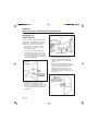
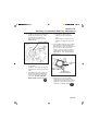
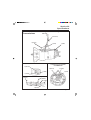
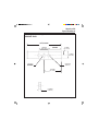
Checking and Adjusting
the Oil Level
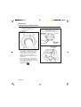
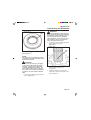
See Figure 2–2.
1. Make sure of the following before
checking the oil level.
CAUTION
Use only the specified type of single
weight oils. Do not use multi-viscosity
oils or EP (Extreme Pressure) gear oils.
Multi-viscosity oils and EP gear oils
may damage components. The use of
multi-viscosity or EP gear oils voids the
warranty.
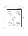
3. Check the oil level. The oil level must
be even with the bottom of the hole of
the fill plug.
If foam appears when the plug is
removed, air has not been removed
from the oil. Install the plug and wait
for the air to dissipate.
If oil flows from the hole when the plug
is loosened, the oil level is high. Let
the oil drain until the oil is at the
specified level.
If the oil level is below the bottom of
the hole of the fill plug, add the
specified oil.
4. Install and tighten the fill plug to
35-50 lb-ft (48-67 N.m).
5. Operate the vehicle for five minutes.
Check for correct operation.
Figure 2–2
OIL LEVEL MUST
BE EVEN WITH
BOTTOM OF
FILL PLUG HOLE
a. The oil is at room temperature
b. Wait ten minutes after the vehicle is
parked before checking the level.
c. Make sure the vehicle is parked on
a level surface.
2. Clean the area around the fill plug.
Remove the fill plug from the side of
the transmission.
FILL
PLUG
DRAIN
PLUGS
Page 21
Section 2
Lubrication and Maintenance
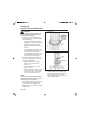
Checking the Condition of
the Breather Vent
Make sure the breather vent is not damaged. Remove all dirt and oil from the
screen in the breather vent. Figure 2–3.
Figure 2–3
Inspecting the
Transmission for Leaks
and Damage
Inspect the transmission for cracks, leaks
and damage. Make sure the leaks are
transmission oil.
CAUTION
Repair all leaks. If leaks are not repaired, the transmission will be damaged.
Checking the Torque of the
Fasteners
Check the torque on the following. See the
torque chart in Section 20, “Specifications”.
● Clutch housing to engine flywheel.
● Top cover housing to main case.
● All electrical switches on the top cover
housing.
● Drain and fill plugs.
● PTO covers to main case.
● Auxiliary case to main case.
● Output bearing retainer to auxiliary
case.
● Piston housing cover to auxiliary
case.
● Auxiliary countershaft cover to
auxiliary case.
● Transmission to frame brackets.
● Output yoke to output shaft.
● Shift cover housing to top cover housing.
Page 22
Inspect the following areas for leaks.
● The output yoke and the oil seal in the
output bearing retainer on the auxiliary
case.
● The PTO covers on the main case.
● The auxiliary case to main case.
● The main case and the clutch housing.
● The clutch housing to flywheel housing.
● The auxiliary countershaft covers.
● The slave valve to the main case.
● The shift lever and tower assembly to
the top cover.
● The top cover to the main case.
● The fill and the drain plugs.
● The output bearing retainer to the
auxiliary case.
● The input bearing retainer to the main
case.
●
Speedometer bore or electronic speed
pick-up in the output bearing retainer.
Section 2
Lubrication and Maintenance
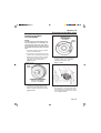
Draining and Replacing
the Transmission Oil
NOTE:
Drain the oil when the transmission is
hot.
1. Make sure the vehicle is parked on a
level surface. Put a large container
under the transmission. Put a screen
on top of the container.
NOTE:
Meritor recommends replacing the
magnetic drain plug each time the oil is
changed. Use the correct part. Pipe
plugs will leak if used as a drain plug.
The magnetic drain plug can be reused
if, after cleaning, the plug has a minimum pick-up capacity of 1.5 pounds
(0.7 kilograms) of low carbon steel.
2. Remove the drain plugs from the
bottom of the transmission. Drain and
discard the oil.
Inspect the O-rings on the drain plugs.
Replace worn or damaged O-rings.
Inspect the screen on top of the container for metal particles and damaged
particles. Service the transmission as
necessary.
3. If the transmission is disassembled or
replaced and an oil cooler is used,
remove the cooler. Remove and
discard the oil from the cooler and the
oil lines. Install the oil cooler and the
lines. Tighten the fittings to the specified torque of the manufacturer of the
vehicle.
4. Install and tighten the drain plug to 3550 lb-ft (48-67 N.m).
5. Clean the area by the fill plug. Remove the fill plug from the side of the
transmission.
CAUTION
Use only the specified type of single
weight oils. Do not use multi-viscosity
oils or EP (Extreme Pressure) gear oils.
Multi-viscosity oils and EP gear oils
may damage components. The use of
multi-viscosity or EP gear oils voids the
warranty.
6. Add the specified transmission oil
through the hole for the fill plug.
Add the oil until the oil level is even
with the bottom of the hole of the fill
plug. Figure 2–4.
7. Install and tighten the fill plug to 35-50
lb-ft (48-67 N.m).
8. Operate the vehicle for five minutes.
Check for correct operation.
Figure 2–4
OIL LEVEL MUST
BE EVEN WITH
BOTTOM OF
FILL PLUG HOLE
FILL
PLUG
DRAIN
PLUGS
Page 23
Section 2
Lubrication and Maintenance
Adjusting the Linkage for
the Remote Control
Assembly
Cab-Over-Engine (COE) vehicles use a
remote control assembly on top of the
transmission. Linkage connects the inner
shift lever to a shift lever in the cab of the
vehicle.
The linkage must be adjusted for correct
operation. See the procedure of the manufacturer of the vehicle.
Lubricating the Remote
Control Assembly
Apply grease to the fittings on the linkage
at the interval specified by the manufacturer of the vehicle. Use the grease specified by the manufacturer of the vehicle.
Page 24
Section 3
In-Vehicle Service
Figure 3–1
WARNING
SHIFT LEVER
AND TOWER ASSEMBLY
To prevent serious eye injury, always
wear safe eye protection when doing
maintenance or service.
Removing the Shift Lever
and Tower Assembly
1. Shift the transmission into the NEUTRAL position. Remove the air from
the air supply system.
2. Disconnect the air lines from the shift
knob at the slave valve.
3. Remove the capscrews and the washers that fasten the shift tower housing
to the top cover housing.
NOTE:
Do not lose any detent springs or balls
when the shift tower housing is removed. If any springs or balls come
out, install the parts in the correct bore.
Install the ball before the spring is
installed.
Installing the Shift Lever
and Tower Assembly
1. Make sure the transmission is in the
NEUTRAL position. Figure 3–2.
Figure 3–2
NEUTRAL
POSITION
4. Remove the shift tower housing and
lever assembly and the gasket from
the top cover housing. Discard the
gasket Figure 3–1.
5. Remove any gasket material between
the shift lever housing and the top
cover housing.
Page 25
Section 3
In-Vehicle Service
CAUTION
The aluminum housing uses a gasket
that is different from the gasket on the
cast iron housing. Use the correct
gasket. If the wrong gasket is used, the
area between the shift tower housing
and the top cover housing will leak.
Figure 3–3
TORQUE SEQUENCE
2. Install a new gasket for the shift tower
housing on the top cover housing.
3. Put the shift tower housing in position
on the top cover housing. Make sure
the bottom of the lower shift lever is
correctly installed between the forks
and the sleeves in the top cover housing. Figure 3–1.
4. Install the mounting capscrews and
washers on the shift tower housing.
Tighten the capscrews to 35-45 lb-ft
(48-61 N.m) in the sequence shown in
Figure 3–3.
Page 26
5. Install the cover (if used) around the
shift tower housing.
6. Operate the vehicle. Make sure the
transmission operates correctly in all
gears.
Section 3
In-Vehicle Service
Removing the Slave Valve
Figure 3–4
SLAVE
VALVE
See Figure 3–4.
1. Remove the air from the air supply
system.
2. Disconnect and mark the air lines from
the slave valve by pushing on the
fitting and pulling on the line.
3. Remove the mounting capscrews and
the washers from the slave valve.
Remove the slave valve.
On Design Level 1 Transmissions,
remove and replace the gasket between the slave valve and the case.
On Design Level 2 Transmissions, a
gasket for the slave valve is not used.
4. Remove the actuator pin, the spring
and the sleeve from the bore in the
main case. Figure 3–5.
Figure 3–5
ACTUATOR PIN
SPRING
Installing the Slave Valve
See Figure 3–4.
1. Lubricate the O-rings on the sleeve
with a silicone lubricant such as Dow
Corning #111 Silicone Grease or
equivalent.
NOTE:
If the part number on the sleeve is 2245H-1126 or 2245-A-1067, replace the
sleeve with part number 2245-U-1165.
2. Install the small end of the sleeve in
the bore in the slave valve.
3. Install the spring on the actuator pin.
Install the pin and spring assembly in
the main case Make sure the tip on
the pin is toward the slave valve
Figure 3–5.
SLEEVE
4. On Design Level 1 Nine-Speed
Transmissions only, install a new
gasket in position on the back of the
slave valve. Design Level 2 Nine and
Ten-Speed Transmissions do not
use a gasket.
5. Install the slave valve and the gasket
in position on the main case.
6. Install the mounting capscrews and
washers for the slave valve. Tighten
the capscrews to 85-115 lb-in
(10-12 N.m).
Page 27
Section 3
In-Vehicle Service
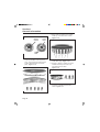
Figure 3–6
RED AIR LINE
-TO SUPPLY PORT
('PS')
BLACK AIR
LINE-TO
PILOT PORT ('P')
Removing the Air Filter
and Regulator Assembly
See Figure 3–7.
Figure 3–7
RED AIR LINE
-TO SUPPLY
('S')
BLACK AIR
LINE-TO
LO RANGE ('L')
SUPPLY
PORT
FILTER AND
REGULATOR
ASSEMBLY
DELIVERY
PORT
BLUE AIR LINE
-TO HI RANGE
('H)
7. Connect the air lines to the slave
valve. Figure 3–6.
a. Connect the BLACK 1/8 or 5/32
inch outer diameter air line to the
pilot port fitting (stamped letter 'P'
on the valve).
b. Connect the RED 1/8 or 5/32 inch
outer diameter air line to the pilot
supply port fitting (stamped letters
'PS' on the valve).
c. Connect the RED 1/4 or 5/16 inch
outer diameter air line to the supply
fitting (stamped letter 'S').
d. Connect the BLACK 1/4 or 5/16
inch outer diameter air line to the
LO range fitting (stamped letter'L').
e. Connect the BLUE 1/4 or 5/16 inch
outer diameter air line to the HI
range fitting (stamped letter 'H').
8. Operate the vehicle. Check the air
shift system for correct operation.
Page 28
1. Remove the air from the air supply
system.
2. Disconnect and mark the air lines on
the filter and regulator assembly.
3. Remove the mounting capscrews and
the washers from the filter and regulator assembly. Remove the filter and
regulator assembly.
4. On thirteen-speed transmissions,
remove the O-ring from between the
filter and regulator assembly and the
piston housing cover. Figure 3–8.
Section 3
In-Vehicle Service
Figure 3–9
Figure 3–8
FILTER AND
REGULATOR
ASSEMBLY
O-RING
SUPPLY
PORT
FILTER AND
REGULATOR
ASSEMBLY
DELIVERY
PORT
Installing the Air Filter and
Regulator Assembly
Removing the Output Yoke
and the Oil Seal
See Figure 3–7.
NOTE:
1. On thirteen-speed transmissions,
lubricate the O-ring with a silicon
lubricant such as Dow Corning #111
Silicone Grease or equivalent. Put the
O-ring for the filter and regulator assembly in the port in the piston housing
cover. Figure 3–7.
1. Put the filter and regulator assembly
on the top of the range cylinder.
2. Install the mounting capscrews and
washers. Tighten the capscrews to
85-115 lb-in (10-12 N.m).
Before replacing the oil seal, make sure
of the following:
1. The oil seal leaks. The lip of the oil
seal is packed with grease. Under
normal conditions, the area between
the lip of the oil seal and the yoke is
“wet”. To check if the seal leaks,
clean the area around the seal
(Make sure the oil is at the specified
level.). If drops of oil appear, the
seal must be replaced. If the area
between the lip of the seal and the
yoke is “wet”, do not replace the oil
seal.
3. Connect the RED air line to the DELIVERY port on the filter and regulator
assembly. Connect the air line from the
air supply system to the SUPPLY port
on the slave valve (stamped letter “S”
on the valve. Figure 3–9.
2. The correct oil is in the transmission. If the wrong oil is used, the oil
seal will be damaged and leak. See
“Transmission Oil Specifications” in
Section 20.
4. Operate the vehicle. Check the air
shift system for correct operation.
3. The yoke is not worn or damaged. If
the yoke is worn or damaged, replace the yoke. Do not repair yokes.
Page 29
Section 3
In-Vehicle Service
4. Use the correct tool and the correct
procedure to install the seal. Use
Seal Driver Tool, Meritor Part Number 3256-Z-1014 or Kent-Moore Part
Number J-39161 to install the seal.
Do not remove the output bearing
retainer to install the seal. If the
correct tool and/or the correct procedure is not used, the seal will
leak.
WARNING
5. Remove the yoke from the output
shaft. Remove the speedometer tone
ring or drive gear from the yoke. Replace the yoke if worn or damaged.
6. Use a slide hammer and puller, such
as Snap-On Light Duty Puller Set,
CG2400B, or equivalent, to remove the
seal from the retainer. Discard the
seal. Figure 3–11.
Figure 3–11
Do not work under a vehicle supported
only by jacks. Jacks can slip or fall over
and cause serious personal injury.
Support the vehicle with safety stands.
Block the wheels to prevent the vehicle
from moving.
1. Put the transmission in NEUTRAL.
Make sure the parking brake is
applied.
OIL SEAL
PULLER
2. Disconnect the driveshaft from the
output yoke of the transmission.
3. Put a holding tool, such as Kent-Moore
Tool, J-3453, Flange/Yoke Holding
Bar, or equivalent, on the yoke.
4. Put a 2-3/4 inch socket on the nut that
fastens the yoke to the output shaft.
Remove and discard the nut.
Figure 3–10.
Figure 3–10
Installing the Oil Seal and
the Output Yoke
1. Inspect the bore for the seal in the
output bearing retainer and the seal
journal on the output yoke for wear or
damage. Replace the retainer if worn
or damaged.
2. Lubricate the outer surface of the
output bearing retainer where the seal
is installed with the oil that is used in
the transmission.
HOLDING
TOOL
Page 30
YOKE
Section 3
In-Vehicle Service
CAUTION
Hold the seal only on the outer diameter. Do not touch the inner diameter of
the seal. Touching contaminates the
inner diameter of the seal and causes a
leak between the shaft and the seal.
3. Install the oil seal in the output bearing
retainer.
5. Clean the seal driver tool. Put the oil
seal on the seal driver tool so that the
spring is away from the tool. Make
sure the seal is flat against the surface
of the tool. Figure 3–13.
Figure 3–13
SPRING
CAUTION
Use only the specified seal driver tool.
If a different driver tool is used, the seal
will not be installed at the correct depth
and will leak.
4. Use seal driver tool, Meritor Part Number 3256-Z-1014 or Kent-Moore Part
Number J-39161, to install the seal.
Clean and inspect the tool. Replace
the tool if the area that touches the
seal is worn or damaged. Figure 3–12.
6. Drive the seal into the retainer until the
flange on the tool touches the retainer.
Make sure there are no gaps between
the tool and the retainer.
Figure 3–12
CAUTION
Use a cleaning solvent to clean the
yoke. Do not use a crocus cloth to
polish the journal of the yoke. If a
crocus cloth is used, the seal will leak.
SEAL
DRIVER
TOOL
7. Clean the yoke with a cleaning solvent.
Lubricate the journal and splines in the
yoke with the oil that is used in the
transmission.
CAUTION
On 115 and 125 Series transmission,
use the sleeve inside the seal driver
tool.
On 135, 145 and 155 Series transmissions, remove the sleeve from the
inside of the seal driver tool.
Make sure the speedometer drive gear
or tone ring is correctly installed or the
output shaft seal may be damaged
when the yoke is installed.
8. Install the speedometer drive gear or
tone ring on the yoke.
Page 31
Section 3
In-Vehicle Service
9. Install the yoke on the output shaft.
Put a holding tool on the yoke. Figure
3–14.
Figure 3–14
CAUTION
Do not tighten the yoke nut more than
500 lb-ft (677 N.m) or the output bearing
will be damaged.
10. Install a new nut that fastens the yoke
on the output shaft. Tighten the nut to
450-500 lb-ft (610-677 N.m). Figure
3–14.
11. Connect the driveshaft to the output
yoke. Install and tighten the fasteners
according to the specifications and
procedures of the manufacturer of the
vehicle.
12. Operate the vehicle. Make sure the oil
seal does not leak.
Page 32
HOLDING
TOOL
YOKE
Section 3
In-Vehicle Service
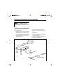
Removing and Installing
the Remote Control
Assembly
NOTE:
See the recommended procedure from
the manufacturer of the vehicle. The
following is a general procedure to
remove and install the remote control
assembly.
To adjust the distance, loosen the jam
nuts and move the rod to the correct
distance. Tighten the jam nuts to 3550 lb-ft (47-67 N.m).
8. Adjust the linkage according to the
procedure of the manufacturer of the
vehicle.
9. Operate the vehicle and check for
correct operation.
Figure 3–15
1. Raise the cab according to the procedure of the manufacturer of the vehicle.
2. Measure the length of the adjusting
rod from the centerline of each ball
socket as shown in Figures
3–15 and 3–16. Mark the location of
the adjusting rod and the ball sockets.
ONE-PIECE
ADJUSTING
ROD
ADJUST TO
SPECIFICATIONS
OF VEHICLE
MANUFACTURER
3. Disconnect the linkage to the remote
control assembly.
4. Remove the capscrews that fasten the
remote control housing to the top cover
housing. Remove the housing. Remove and discard the gasket. Remove
any gasket material between the
remote control housing and the top
cover housing.
Figure 3–16
5. Install a new gasket on the transmission.
6. Put the remote control housing in
position. Install and tighten the capscrews to 35-45 lb-ft (47-61 N.m).
7. Connect the linkage to the outer shift
lever of the remote housing. Install
and tighten the nut to 12-18 lb-ft (1724 N.m).
TWO-PIECE
ADJUSTING
ROD
ADJUST TO
SPECIFICATIONS
OF VEHICLE
MANUFACTURER
8. Adjust the length of the adjusting rod
to the distance measured in step 2 or
to the distance specified by the manufacturer of the vehicle. Figures 3–15
and 3–16.
Page 33
Section 4
Removing and Installing the Transmission
WARNING
To prevent serious eye injury, always
wear safe eye protection when doing
maintenance or service.
4. Put marks on the yoke or the flange of
the driveshaft and the output shaft of
the transmission. The marks on the
driveshaft and the output shaft make
sure the driveshaft is correctly reinstalled.
5. Remove the driveshaft.
Removing the
Transmission
See the recommended procedure from the
manufacturer of the vehicle to remove the
transmission. Some vehicles require that
the engine is supported when the transmission is removed. The following is a
general procedure to remove the transmission.
1. Remove the air from the air supply
system.
2. Put a large container under the transmission. Remove both drain plugs
(and if necessary, the cooler lines).
Drain and discard the oil. Figure 4-1.
Figure 4-1
OIL LEVEL MUST BE EVEN
WITH BOTTOM OF FILL
PLUG HOLE
6. Disconnect all the electrical connections (if used) for the back-up lamp
switches, the neutral safety switch and
the temperature indicator.
7. Disconnect and mark all the air lines
from the transmission.
8. Disconnect the speedometer connections from the output bearing retainer.
9. If used, remove the spring from the
clutch lever on the transmission. Mark
and disconnect the clutch linkage from
the clutch housing on the transmission.
10. If a hydraulic system is used on the
clutch, disconnect the push rod and
the spring from the release fork. Remove the hydraulic cylinder from the
bracket on the transmission. Use
wires to support the cylinder on the
frame.
WARNING
Make sure the transmission is securely
supported on the overhead hoist or the
jack. If the transmission is not securely
supported, the transmission may fall
and cause serious personal injury or
damage.
FILL
PLUG
DRAIN
PLUG
3. Remove the shift lever from the transmission. If necessary, remove the shift
tower assembly from the transmission.
Page 34
11. Support the transmission with an over
head hoist or with a transmission jack.
Make sure the transmission is securely
supported.
12. Remove the fasteners that attach the
transmission to the brackets on the
frame.
Section 4
Removing and Installating the Transmission
CAUTION
Make sure the transmission does not
hang by the input shaft. The clutch
assembly and the pilot bearing will be
damaged if the transmission is supported by the input shaft.
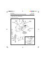
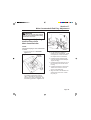
Figure 4-3
CLUTCH
BRAKE
10. Remove the bolts and the washers that
attach the clutch housing to the engine. Pull the transmission straight out
from the flywheel housing. Remove
the transmission from the vehicle.
Figure 4-2.
11. If used, remove the clutch brake assembly from the input shaft of the
transmission. Inspect transmission
input bearing retainer surface for
excessive wear which can affect the
clutch adjustment. Figure 4-3.
Figure 4-2
TRANSMISSIONPULL
TRANSMISSION
STRAIGHT OUT
INPUT SHAFTMAKE SURE
TRANSMISSION
IS NEVER
SUPPORTED
BY INPUT SHAFT
Page 35
Section 4
Removing and Installing the Transmission
Figure 4-5
Installing the
Transmission
See the recommended procedure from the
manufacturer of the vehicle to install the
transmission. The following is a general
procedure to install the transmission.
1. Inspect the clutch housing for wear
and damage. Replace worn and
damaged housings.
2. Inspect the cross shaft bores in the
housing. Make sure plugs are in the
bores that are not used. If the bores
are not plugged, dirt and contaminants
go into the clutch housing and damage
the clutch. Figure 4-4.
Figure 4-4
INSPECTION COVER
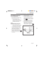
4. Inspect the input bearing retainer on
the transmission. Check the area
where the clutch brake touches the
retainer. Replace worn or damaged
retainers.
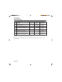
5. Measure the distance from the top of
the splines on the input shaft to the top
of the bearing retainer as shown in
Figure 4-6. If the distance is more
than 8.72 inches (221.48 mm), the
input bearing retainer is worn and must
be replaced.
MAKE SURE
THE UNUSED
BORES ARE
PLUGGED
3. Make sure an inspection cover is
installed on the bottom of the clutch
housing. If an inspection cover is not
used, dirt and contaminants go into the
clutch housing and damage the clutch.
Figure 4-5.
Page 36
Figure 4-6
IF DIMENSION 'A' IS
MORE THAN
8.72 INCHES (221.48 mm),
REPLACE THE INPUT
BEARING RETAINER
Section 4
Removing and Installating the Transmission
6. Inspect the shaft and the release fork.
Make sure the release fork is straight
and the tips of the fork are not worn or
damaged. Replace forks that are worn
or damaged. Figure 4-7.
Figure 4-7
Figure 4-8
CROSS SHAFT
MUST ROTATE
FREELY
MAKE SURE SPLINES
ARE NOT DAMAGED
TIPS ON
FORK MUST
NOT BE
WORN OR
DAMAGED
7. Make sure the cross shafts rotate
freely in the clutch housing. Make sure
the shaft does not have any excessive
radial (side-to-side) movement in the
housing. Inspect the bushings for the
shaft in the housing. Replace bushings and shafts that are worn or damaged.
8. Inspect the splines on the input shaft.
Make sure the splines are not worn or
damaged. Inspect the area of travel
for the release bearing for damage.
Use an emery cloth to remove small
scratches from the input shaft. Replace input shafts that are worn or
damaged. Figure 4-8.
10. Inspect the clutch brake. If the tabs or
the body is worn or damaged, replace
the clutch brake. Inspect the lining
material on the clutch brake. Replace
the clutch brake if the lining is worn or
damaged. Figure 4-9.
11. If removed, install the clutch brake on
the input shaft of the transmission.
Make sure the large part of the brake
is toward the input bearing retainer and
the tabs on the brake engage the slots
in the input shaft. Figure 4-9.
Figure 4-9
CLUTCH
BRAKE
9. Inspect the end of the input shaft
where the pilot bearing is installed. If
the end is worn or damaged, replace
the input shaft and the pilot bearing.
Figure 4-8.
Page 37
Section 4
Removing and Installing the Transmission
12. Put the transmission in gear.
WARNING
Make sure the transmission is securely
supported on the overhead hoist or
jack. If the transmission is not securely
supported, the transmission may fall
and cause serious personal injury or
damage.
13. Put the transmission on a transmission
jack or an overhead hoist.
14. If installed, remove the inspection
cover from the clutch housing.
CAUTION
Be careful when installing the input
shaft of the transmission in the hubs of
the disc. If the transmission is forced
or jammed, the clutch discs or the
clutch housing will be damaged. Also,
do not let the transmission hang or be
supported by the clutch or the discs.
The clutch or the discs are damaged
when the transmission is not correctly
installed.
15. Install the transmission according to
the following procedure. Figure 4-10.
a. Put the transmission so that the
input shaft is aligned with the pilot
bearing.
b. Move the input shaft into the clutch
housing. Make sure the two tips of
the release fork are installed between the release bearing assembly and the clutch cover.
c. If necessary, rotate the output shaft
of the transmission to align the
splines on the input shaft with the
teeth in the hubs of the clutch
discs.
Figure 4-10
SEE VIEW A
INPUT SHAFT
MUST BE
ALIGNED
WITH PILOT
BEARING
Page 38
VIEW A
TIPS OF RELEASE FORK
MUST BE INSTALLED
BETWEEN RELEASE
BEARING AND CLUTCH
Section 4
Removing and Installating the Transmission
d. Push the transmission against the
flywheel housing.
16. Install the capscrews that fasten the
clutch housing on the transmission to
the flywheel housing. Tighten the
capscrews to the specified torque and
the sequence specified by the manufacturer of the vehicle.
17. Align the transmission with the brackets on the frame. Install the fasteners
that hold the transmission on the
brackets. Tighten the fasteners to the
torque specified by the manufacturer of
the vehicle.
18. Remove the transmission jack or lifting
device from the transmission.
Install and tighten the fasteners according to the specifications and the
procedure of the manufacturer of the
vehicle.
24. Connect the shift lever assembly to the
transmission. If removed, install the
shift tower assembly on the transmission.
25. Lubricate the clutch housing, the cross
shaft bushings and the release bearing
housing. See the procedure of the
manufacturer of the vehicle.
26. Adjust the clutch and/or the linkage.
See the procedure of the manufacturer of the vehicle
CAUTION
19. If a hydraulic assist system is used for
the clutch, install the slave cylinder in
the bracket on the transmission. Connect the push rod to the release lever
on the transmission. Connect the
spring to the release lever.
Make sure the inspection cover on the
clutch housing is used. If an inspection
cover is not used, dirt and contaminants get into the clutch housing and
damage the clutch.
20. Connect the clutch linkage to the
release lever on the transmission.
Connect the spring to the release
lever.
27. Install the inspection cover. Install and
tighten the capscrews. Tighten the
capscrews to the specified torque of
the manufacturer of the vehicle.
21. Connect the air lines to the transmission.
22. Connect the electrical connectors to
the transmission.
23. Connect the driveshaft to the output
yoke on the transmission. Make sure
the alignment marks on the output
yoke and the driveshaft that were
made during removal are aligned.
CAUTION
Use the specified oil. Do not use multiviscosity or EP (Extreme Pressure) GL5 gear oils. The wrong oil will damage
the transmission.
28. Clean the area by the fill plug. Remove the fill plug from the transmission. Add the specified oil until the oil
level is even with the bottom of the
hole of the fill plug. Figure 4-11.
Page 39
Section 4
Removing and Installing the Transmission
See “Transmission Oil Capacities” and
“Transmission Oil Specifications” in
Section 20, “Specifications”.
Install and tighten the fill plug to 35-50
lb-ft (48-67 N.m).
Figure 4-11
OIL LEVEL MUST BE EVEN
WITH BOTTOM OF FILL
PLUG HOLE
29. Operate the vehicle. Check for correct
operation.
FILL
PLUG
Page 40
DRAIN
PLUG
Section 5
Overhauling the Shift Lever and Tower Assembly
WARNING
To prevent serious eye injury, always wear safe eye protection when doing maintenance or service.
Disassembling the Aluminum Shift Lever and Tower
Assembly
See Figure 5–1.
Figure 5–1
CLAMP
BOOT
CLAMP
SNAP
RING
UPPER
RETAINER
PLATE
LEVER
LOWER
RETAINER
PLATE
SPRING
WASHERS
HOUSING
SET
SCREW
Page 41
Section 5
Overhauling the Shift Lever and Tower Assembly
NOTE:
If an aluminum shift tower assembly is
replaced, replace the entire assembly
with a cast iron shift tower assembly.
Make sure the gasket between the shift
tower housing and the top cover housing is replaced. A different gasket is
used on the aluminum than on the cast
iron housing.
4. Put the assembly in a vise with brass
jaws. Make sure the inside of the
housing is away from you.
5. Remove the snap ring that fastens the
upper retainer plate and the lever in
the housing. Figure 5–3.
Figure 5–3
SNAP
RING
1. Remove the shift lever and tower
assembly as described in Section 3,
“In–Vehicle Service”.
2. If necessary, separate the upper shift
lever from the lower shift lever. See
the following.
a. If clips are used, remove one clip.
Remove the clip and pin assembly
from the lever. Remove the bushings. Figure 5–2.
b. If a bolt and nut is used, remove
the nut and the bolt.
c. Remove the upper shift lever from
the lower shift lever. Figure 5–2.
6. Remove the set screws from the side
of the housing. Remove the lower
retainer from the housing. Figure 5–4.
Figure 5–4
Figure 5–2
HOUSING
BOLT
NUT
SET
SCREW
CLIP
PIN
BUSHING
3. Remove the clamps that fasten the
boot to the housing. Remove the boot
from the housing and the lower shift
lever.
Page 42
Section 5
Overhauling the Shift Lever and Tower Assembly
7. Lift on the lever to remove the lever
and the upper retainer plate from the
housing. Figure 5–5.
NOTE:
Two or three spring washers may be
used in the housing. Make sure the
same number of washers are installed.
8. Remove the spring washers from the
housing. Figure 5–6.
9. Inspect all parts. See “Repairing or
Replacing the Parts” in Section 1.
Figure 5–5
Assembling the Aluminum
Gear Shift Lever and
Tower Housing
See Figure 5–1.
NOTE:
If an aluminum housing is being replaced, replace the entire assembly with
a cast iron shift tower housing.
1. Put the housing in a vise with brass
jaws. Make sure the outside of the
housing is toward you.
NOTE:
LEVER
UPPER
RETAINER
Two or three spring washers may be
installed in the housing. Make sure the
same number of washers are installed.
2. Install the spring washers in the bottom
of the housing. Make sure the large
ends of the washers touch and the
bevels of the washers are installed
away from each other as shown in
Figure 5–7.
Figure 5–7
Figure 5–6
WASHERS(2)
WASHERS(2)
Page 43
Section 5
Overhauling the Shift Lever and Tower Assembly
3. Install the lower retainer plate in the
housing. Make sure the tabs of the
retainer are in the slots in the housing.
Figure 5–9
SNAP
RING
4. Install the lever so that the slots in the
lever are installed over the pins.
Figure 5–8.
5. Install the upper retainer plate over the
lever and in the housing. Make sure
the tabs on the plate are installed in
the slots in the housing. On some
housings, make sure the pins in the
plate are aligned with the slots in the
ball on the lever. Figure 5–8.
Figure 5–8
Figure 5–10
LEVER
HOUSING
SET
SCREW
UPPER
RETAINER
6. Install the snap ring that fastens the
upper retainer plate and the lever in
the housing. Figure 5–9.
7. Install and tighten the set screw that
fastens the upper retainer plate in the
housing. Figure 5–10.
Page 44
8. Install the boot on the housing. Make
sure the lip on the boot is installed in
the groove in the housing. Install the
clamps or cable ties that fasten the
boot to the lower lever and the housing. Figure 5–11.
Section 5
Overhauling the Shift Lever and Tower Assembly
Figure 5–11
BOOT
Figure 5–12
BOLT
NUT
CLIP
PIN
9. If removed, connect the upper shift
lever assembly to the lower lever. See
the following: Figure 5–12.
a. Install the upper shift lever assembly on the lower lever. Make sure
the bores for the retainers are
aligned.
BUSHING
b. If clips are used, install a bushing in
each side. Install a clip on one end
of the pin. Install the pin in the
bores. Install the clip on the other
end of the pin.
c. If a bolt and nut is used, install the
bolt in the bores. Install and tighten
the nut to 8-12 lb-ft (11-16 N.m).
Page 45
Section 5
Overhauling the Shift Lever and Tower Assembly
Figure 5–13
WARNING
To prevent serious eye injury, always wear safe eye protection when
doing maintenance or service.
Disassembling the
Cast Iron Shift Lever and
Tower Assembly
CLAMP
BOOT
SPIRAL
SNAP RING
SPRING
SPACER
See Figure 5–13.
1. Remove the shift lever and tower
assembly as described in Section 3,
“In–Vehicle Service”.
2. If necessary, separate the upper shift
lever from the lower shift lever. See
the following.
LEVER
a. If clips are used, remove one clip.
Remove the clip and pin assembly
from the lever. Remove the bushings. Figure 5–14.
b. If a bolt and nut is used, remove
the nut and the bolt. Figure 5–14.
c. Remove the upper shift lever from
the lower shift lever.
HOUSING
3. Remove the clamps that fasten the
boot to the housing. Remove the boot
from the housing and the shift lever.
4. Put the assembly in a vise with brass
jaws. Make sure the inside of the
housing is toward you.
5. Remove the spiral snap ring that
fastens the spring, the spacer and the
lower lever in the housing.
Page 46
6. Lift on the lower lever to remove the
lever. Remove the spring and the
spacer from the lower lever.
7. Inspect all parts. See “Repairing or
Replacing the Parts” in Section 1.
Section 5
Overhauling the Shift Lever and Tower Assembly
3. Install the spacer over the lower lever.
Install the assembly in the housing.
Figure 5–14
4. Install the spring over the lower lever
in the housing.
BOLT
NUT
CLIP
PIN
BUSHING
Assembling the Cast Iron
Shift Lever and Tower
Assembly
See Figure 5–13
1. Put the housing in a vise with brass
jaws. Make sure the outside of the
housing is toward you.
2. Install the lower lever in the housing.
Make sure the slots on the ball of the
lever are aligned with the pins in the
housing.
5. Install the spiral snap ring over the
lower lever in the housing. Make sure
the snap ring is completely installed in
the groove in the housing.
6. Install the boot on the housing. Make
sure the lip on the boot is installed in
the groove in the housing. Install new
cable ties that fasten the boot to the
housing.
7. If removed, connect the upper lever to
the lower lever. See the following:
Figure 5–14.
a. Install the upper lever of the lower
lever. Make sure the bores for the
retainers are aligned.
b. If clips are used, install a bushing in
each side. Install a clip on one end
of the pin. Install the pin in the
bores. Install the clip on the other
end of the pin.
c. If a bolt and nut is used, install the
bolt in the bores. Install and tighten
the nut to 8-12 lb-ft (11-16 N.m).
Page 47
Section 6
Overhauling the Remote Control Assembly
WARNING
To prevent serious eye injury, always wear safe eye protection when
doing maintenance or service.
Disassembling the
Remote Control Assembly
Refer to Figure 6–1.
1. Remove the set screw that fastens the
outer shift lever to the shaft. Remove
the lever.
2. Remove and discard the two tie straps
that fasten the boot to the housing.
Remove the boot.
3. Remove the lockwire and the set
screw that fasten the inner shift lever
to the shaft. Remove the shaft and the
inner shift lever.
4. Inspect the bushings in the housing. If
worn or damaged, use a driver tool to
remove the bushings.
5. If necessary, loosen the sockets and
remove the adjusting rod.
Figure 6–1
HOUSING
BUSHINGS
SHAFT
STRAP
BOOT
STRAP
SET SCREW
OUTER
SHIFT
LEVER
INNER SHIFT
LEVER
LOCK
WIRE
SET
SCREW
ADJUSTING ROD
(ONE-PIECE SHOWN)
SOCKET
Page 48
Section 6
Overhauling the Remote Control Assembly
Assembling the Remote
Control Assembly
1. Do the following to the set screws that
fasten the levers to the shaft.
a. Clean the threads of the set screws
with Loctitie® Safety Solvent
(Meritor part number 2297-P-6412)
or equivalent. Make sure all dirt is
removed from the threads.
NOTE:
See the specifications of the sealant
manufacturer for the “cure” time.
b. Apply Loctite® #242 (Meritor part
number 2297-V-2430) or equivalent
to the threads of the set screws.
5. Fill the area between the bushings with
multi-purpose grease.
6. Put the inner shift lever in position in
the housing. Install the shaft in the
lever. Install and tighten the set screw
to 32-40 lb-ft (44-54 N.m). Install the
lockwire.
7. Install the boot over the shaft and on
the housing. Install new tie straps.
8. Put the outer shift lever on the shaft.
Make sure the outer shaft lever is
aligned with the inner shaft lever.
Install and tighten the set screw to 3240 lb-ft (44-54 N.m). Figure 6–2.
Figure 6–2
2. Lubricate the bushings with a lithium
12-hydroxy stearate grease such as
Multi-Purpose grease, Meritor specification O-617-A or equivalent.
3. If removed install the adjusting rod
assembly in the housing. Tighten the
socket to 35-50 lb-ft (47-68 N.m).
4. If removed, use a driver tool to install
the bushings.
LEVERS MUST
BE ALIGNED
Page 49
Section 7
Removing and Installing the Top Cover Assembly
● Forward position top cover with an
“X” shift pattern.
WARNING
To prevent serious eye injury, always
wear safe eye protection when doing
maintenance or service.
Standard position top covers have the
detent balls and springs under the shift
lever housing.
Removing the Top Cover
Assembly
Forward position covers have the detent springs and balls under a plate
behind the shift lever housing.
NOTE:
Top covers with an “X” shift pattern
have a stud and a nut that fastens the
rocking lever assembly to the top cover.
Four different top cover assemblies are
available. See Figure 7–1.
● Standard position top cover with a
standard shift pattern.
1. Shift the transmission into the NEUTRAL position.
● Standard position top cover with an
“x” shift pattern.
2. Remove the transmission (if necessary) and the shift lever and tower
assembly as described in Section 3,
“In–Vehicle Service”.
● Forward position top cover with a
standard shift pattern.
Figure 7–1
STANDARD POSTION
TOP COVER
—"X" SHIFT PATTERN
STANDARD POSTION
TOP COVER
—STANDARD SHIFT PATTERN
FORWARD POSITION
TOP COVER
—STANDARD SHIFT PATTERN
Page 50
INDICATES
"X" BAR
FORWARD POSTION
TOP COVER
—"X" SHIFT PATTERN
Section 7
Removing and Installating the Top Cover Assembly
NOTE:
Figure 7–2
If a heavy-duty detent spring is used,
the spring (different color) is in the bore
on the slave valve side of the transmission.
DETENT
SPRING
DETENT
BALL
3. Remove the three detent springs from
the top cover from the holes in the top
cover. Figure 7–2.
4. Use a magnet to remove a detent ball
from the each of the three holes.
Figure 7–2.
5. Remove the mounting capscrews and
washers from the top cover.
CAUTION
Use a rubber mallet or “dead blow”
hammer to separate the top cover from
the transmission case. Do not use pry
bars or screwdrivers to separate the
cover from the case. Pry bars or screwdrivers may damage the cover and case
mounting surfaces. If the cover is still
difficult to remove, remove the slave
valve and the interlock pin from the
main case.
HEAVY-DUTY
SPRING
LOCATION
(IF USED)
Figure 7–3
TOP
COVER
6. Remove the top cover from the transmission case. Figure 7–3.
7. Use a scraper to remove the sealant
material from the top cover and the
transmission case.
Page 51
Section 7
Removing and Installing the Top Cover Assembly
Installing the Top Cover
Assembly
1. Inspect the tips of the forks. If the tips
of the forks are worn or damaged,
replace the forks.
Inspect the shift sleeves. If the
sleeves are worn or damaged, replace
the sleeves.
To replace the fork or the sleeve, see
Section 8, “Overhauling the Top
Cover”.
2. Inspect the set screws, if the set
screws are loose, see the following:
a. Clean the threads of the set
screws. Make sure all dirt is removed from the threads.
4. Make sure the transmission is in the
NEUTRAL position.
5. Use Loctite® Master Gasket Sealant®,
#5699 (Meritor Part Number
2297-A-7021) and a sealant dispenser,
to put a new 1/8 inch (2 mm) sealant
pattern for the top cover on the case.
See “Gasket Sealant” in Section 1.
Figure 7–4.
Figure 7–4
FOUR HOLES
SURROUNDED
BY SEALANT
NOTE:
See the specifications of the sealant
manufacturer for the “cure” time.
TRANSMISSION CASE
b. Apply Loctite® #242 (Meritor Part
Number (2297-V-5430) or
equivalent to the threads of the
capscrews
NOTE:
c. Tighten the capscrews to the
torque in the “Torque Specifications
Chart”.
If the top cover is difficult to install,
remove the slave valve and the interlock pin from the main case.
3. Inspect the lockwire. If the lockwire is
missing or damaged, see the following:
a. Install the new lockwire.
b. Bend the wire towards the
capscrew.
c. Twist the wire at least once
between the parts. On the 1-2
sleeve and fork assembly, the wire
can be wrapped around the shaft.
Page 52
6. Install the top cover. Make sure the
cover is in the NEUTRAL position.
Make sure the forks of the cover
engage the collars in the transmission
case. Figure 7–5.
Section 7
Removing and Installating the Top Cover Assembly
Figure 7–5
Figure 7–6
TOP
COVER
DETENT
SPRING
DETENT
BALL
HEAVY-DUTY
SPRING
LOCATION
(IF USED)
7. Install the mounting capscrews and
washers for the top cover. Tighten the
capscrews to 25-35 lb-ft (34-47 N.m).
8. Install a detent ball in each of the three
holes in the top cover. Figure 7–6.
NOTE:
NOTE:
If a heavy-duty detent spring is used,
install the spring (different color) in the
bore on the slave valve side of the
transmission.
9. Install a spring on top of each detent
ball in the holes in the top cover.
Figure 7–6.
Replace the detent springs as a set.
Use the “yellow” spring (Meritor part
number 2258-D-1278) in all the holes.
Page 53
Section 8
Overhauling the Top Cover Assembly
Standard Pattern
Top Cover
Disassembling the Standard and Forward Position
Top Cover Assembly
See Figures 8–1 and 8–2.
Figure 8–1
SPRING
REVERSE
SWITCH
PLUG
BREATHER
VENT
REVERSE
SWITCH
PLUG
BALL
LONG PIN
NEUTRAL SWITCH
PLUG
OIL
SCOOP
SHORT PIN
STANDARD
POSITION
HOUSING
(FOR FORWARD
POSITION
HOUSING
SEE BOX)
OIL
SCOOP
COVER
PLATE
GASKET
FORWARD
POSITION HOUSING
Page 54
Standard Pattern
Top Cover
Figure 8–2
Section 8
Overhauling the Top Cover Assembly
BALL
SPRING
CLIP
LOW REVERSE
FORK
SPRING
LOW
REVERSE
SHAFT
1-2 SHAFT BALL
1-2
FORK
PLUNGER
1-2 SLEEVE
BALL
PIN
SET
SCREW
3-4 SLEEVE
3-4 SLEEVE
NEUTRAL
CHECK SHAFT
LOCKWIRE INSTALLATION NOTES:
LOCK
WIRE
3-4 FORK
WARNING
To prevent serious eye injury, always wear safe eye protection when
doing maintenance or service.
1. Trim excess wire to 1/4 inch (6mm).
2. Bend the wire towards the capscrew.
3. Twist the wire at least once between parts.
4. On the 1-2 sleeve, the wire can be
wrapped around the shaft.
5. Make sure the wire does not interfere with
the movement of the rail.
Figure 8–3
SLEEVES IN
NEUTRAL
POSITION
NOTE:
The standard position top cover and the
forward position top cover use different
housings. The forward position housing uses a plate and a gasket installed
over the detent balls and springs.
1. Remove the top cover from the transmission case as described in this
section. Make sure the top cover is in
the NEUTRAL position. Figure 8–3.
Page 55
Section 8
Overhauling the Top Cover Assembly
2. On forward top covers, remove the
capscrews that fasten the spring cover
plate (if installed) to the top cover.
Remove the plate and the gasket.
Standard Pattern
Top Cover
Figure 8–5
NOTE:
If a heavy-duty detent spring is used,
the spring (different color), is in the
bore on the slave valve side of the
transmission.
3. If installed, remove the three detent
springs and balls from the top of the
housing. Figure 8–4.
OIL
SCOOPS
Figure 8–4
7. Remove the set screws that fasten the
shift fork and sleeve assembly to the
shift shafts. Figure 8–6.
Figure 8–6
BALL AND
SPRING
CAUTION
Do not damage the machined surface of
the case. If the surface is damaged, the
case will leak
4. Put the top cover on the bench so that
the forks are toward you or in a vise
with brass protectors on the jaws.
5. Remove the capscrews that fasten the
large and the small oil scoops to the
cover. Figure 8–5.
6. Cut and remove the lock wire on the
fork, sleeve and set screw assembly.
Figure 8–5.
Page 56
8. Remove the 3-4 shift shaft from the
housing. Remove the 3-4 shift sleeve.
Remove the 3-4 shift fork. Figure 8–7.
Standard Pattern
Top Cover
Figure 8–7
Section 8
Overhauling the Top Cover Assembly
3-4 SHIFT
SLEEVE
Figure 8–9
3-4 SHIFT
SHAFT
BALL
3-4 SHIFT
FORK
9. On Design Level 1, nine-speed
transmissions, if necessary, disassemble the 3-4 shift sleeve. Remove
the clip that fastens the 3-4 plunger in
the housing. Remove the plunger.
Figure 8–8.
11. Remove the 1-2 shift shaft, the 1-2
shift fork and the 1-2 shift sleeve from
the housing. Remove the pin interlock
from the end of the 1-2 shift shaft.
Figure 8–10.
Figure 8–10
Figure 8-8
PLUNGER AND
SPRING
1-2 SHIFT
SLEEVE
CLIP
PIN
1-2
SHIFT
FORK
10. Remove the interlock ball from the
bottom of the top bore of the first set of
bores at the rear of the housing.
Figure 8–9.
1-2 SHIFT
SHAFT
12. Remove the interlock ball from the
bottom of the middle bore in the first
set of bores in the housing.
Figure 8–11.
Page 57
Section 8
Overhauling the Top Cover Assembly
Figure 8–11
Standard Pattern
Top Cover
Figure 8–13
REVERSE
SWITCH BORES
LONG PIN
BALL
BREATHER
VENT
13. Remove the neutral check shaft from
the top cover. Figure 8–12.
Figure 8–12
NEUTRAL
CHECK
SHAFT
15. Remove the low-reverse shift shaft.
Remove the low-reverse shift sleeve
and fork assembly. Figure 8–14.
Figure 8–14
LOW-REVERSE
SHIFT SHAFT
LOW-REVERSE
FORK AND
SLEEVE
NOTE:
On standard position top covers, one or
two reverse switches may be used. On
forward position top covers, one reverse switch is used.
14. Remove the reverse switch(es) or
plugs from the top of the housing.
Remove the long pin(s) from each
bore. Figure 8–13.
Page 58
16. If necessary, disassemble the lowreverse sleeve and fork assembly.
Remove the clip that fastens the
plunger in the housing. Remove the
plunger and the spring. Remove the
spring and the ball from the bore next
to the plunger bore. Figure 8–15.
Standard Pattern
Top Cover
Figure 8–15
Section 8
Overhauling the Top Cover Assembly
PLUNGER
AND
SPRING
Figure 8–16
BREATHER
CLIP
17. If necessary, remove the breather from
the top of the cover. Figure 8–16.
18. Remove the neutral safety switch or
plug. Remove the short pin from the
bore. Figure 8–17.
Figure 8–17
NEUTRAL
SWITCH
BORE
SHORT
PIN
19. Inspect all parts. See Section 1,
“Repairing and Replacing the Parts”.
Page 59
Section 8
Overhauling the Top Cover Assembly
Assembling the Standard
and Forward Position Top
Cover Assembly
See Figures 8–1 and 8–2.
NOTE:
The standard position and the forward
position top covers use different housing. The forward housing also uses a
plate and a gasket installed over the
detent balls and springs.
1. Lubricate all the parts of the top cover
with the oil that is used in the transmission.
Standard Pattern
Top Cover
5. Install the breather vent in the top
cover. Tighten to 15-20 lb-ft (21-27
N.m). Figure 8–18.
NOTE:
On standard position top covers, one or
two reverse switches may be used. On
forward position top covers, one reverse switch is used.
6. Install the larger pin(s) in the bore(s)
for the reverse switch. Install the
switches or plugs and tighten to 35-50
lb-ft (48-67 N.m). Figure 8–18.
Figure 8–18
LARGE PINS
(REVERSE SWITCH)
2. Do the following to the set screws that
fasten the shift sleeves and/or forks to
the shift shafts and the capscrews for
the oil scoops.
a. Clean the threads of the fasteners with Loctite ® Safety Solvent
#755 (Meritor part number 2297P-6412) or equivalent. Make
sure all dirt is removed from the
threads.
NOTE:
See the specifications of the sealant
manufacturer for the "cure" time.
b. Apply Loctite® #242 (Meritor part
number 2297-V-5430) or equivalent to the threads of the
fasteners.
3. Install the top cover in a vise with
brass jaws. Make sure the low-reverse
bore holes are toward the bottom of
the vise.
4. Install the short pin in the bore for the
neutral safety switch. Install the switch
or plug and tighten to 35-50 lb-ft (48-67
N.m). Figure 8–18.
Page 60
SHORT PIN (NEUTRAL SAFETY SWITCH)
7. If disassembled, install the plunger
assembly in the low-reverse shift 7fork.
See the following. Figure 8–19.
a. Put the fork in a vise with brass
jaws.
b. Install the spring and the ball in the
bore next to the plunger.
c. Install the plunger and the spring in
the bore of the fork.
d. Install the snap ring that holds the
assembly in the fork.
Standard Pattern
Top Cover
Figure 8–19
Section 8
Overhauling the Top Cover Assembly
PLUNGER
AND
SPRING
Figure 8–20
LOWREVERSE
SHAFT
CLIP
LOWREVERSE
FORK
8. Assemble the low-reverse shift shaft
assembly. See the following procedure.
NOTE:
The low-reverse shaft is the shortest of
the three shafts.
a. Put the low-reverse shift shaft in
the bottom bore of the housing.
Make sure the boss on the end of
the shaft is toward the rear of the
housing. Make sure the detent
grooves in the rail are aligned with
the detent ball holes in the housing.
Figure 8–20.
b. Put the low-reverse shift fork assembly in the top cover so that the
plunger of the fork is toward you.
Make sure the bore of the fork and
sleeve assembly is aligned with the
bore in the housing. Figure 8–20.
CAUTION
After the setscrews with the Loctite®
sealant (see step 2) are tightened to the
specified torque, do not loosen or
tighten. If loosened or tightened, the
set screws must be removed, cleaned
and new sealant applied or the set
screws may loosen during operation.
e. Install the set screw with the Loctite® sealant (see step 2) that
fasten the fork in position on the
shaft. Tighten the set screw to 3545 lb-ft (47-54 N.m). Figure 8–21.
Figure 8–21
SET SCREW
c. Push the shift shaft through the
low-reverse sleeve and fork assembly.
d. Push the shaft through the assembly until the holes in the fork and
shaft are aligned.
Page 61
Section 8
Overhauling the Top Cover Assembly
f. Install the lock wire in the holes in
the capscrew and the fork and
sleeve assembly. Figure 8–21.
9. Install the neutral check shaft in the
bore on the top of the housing. Make
sure the round end of the shaft is
installed toward the low-reverse shift
shaft. Make sure the end of the neutral check shaft touches the slot in the
Low/Reverse shaft. Figure
8–22.
Figure 8–22
NEUTRAL
CHECK
SHAFT
Standard Pattern
Top Cover
11. Assemble the 1-2 shift rail assembly.
See the following procedure.
NOTE:
The 1-2 shift rail is the same size as the
3-4 shift rail and has a hole drilled
through the rail.
NOTE:
Move the low-reverse shift shaft assembly so that the interlock ball is completely installed in the bore. Move the
low-reverse shaft assembly so that the
1-2 rail can be installed.
a. Put the 1-2 shift shaft in the middle
bore of the housing. Make sure the
identification on the end of the shaft
is toward the front of the housing.
Make sure the detent grooves in
the shaft are aligned with the detent
ball holes in the housing. Figure
8–24.
b. Put the interlock pin in the hole
drilled in the side of the 1-2 shift
shaft. Figure 8–24.
10. Put the large interlock ball in the bottom of the middle bore of the first set of
bores on the rear of the housing.
Figure 8–23.
Figure 8–23
Figure 8–24
1-2
SLEEVE
PIN
BALL
1-2
SHAFT
Page 62
Standard Pattern
Top Cover
Section 8
Overhauling the Top Cover Assembly
c. Put the 1-2 shift sleeve in the
housing. Make sure the bore of the
sleeve is aligned with the bore in
the housing. Make sure the
threaded hole in the sleeve is
toward the rear of the housing.
Figure 8–24.
d. Push the shift shaft through the 1-2
shift sleeve. Figure 8–24.
e. Put the 1-2 shift fork in the housing.
Make sure bend on the fork is
installed toward the middle set of
shift rail bores in the top cover
housing. Make sure the bore of the
fork is aligned with the bore in the
housing. Figure
8–25.
f. Push the shift shaft through the 1-2
fork. Figure 8–25.
Figure 8–25
CAUTION
After the set screws with the Loctite®
sealant (see step 2) are tightened to the
specified torque, do not loosen or
tighten. If loosened or tightened, the
set screws must be removed, cleaned
and new sealant applied or the capscrews may loosen during operation.
h. Install the set screw with the Loctite® sealant (see step 2) that
fasten the fork and the sleeve in
position on the shaft. Tighten the
set screw to 35-45 lb-ft (47-54
N.m).
i.
Install the lock wire in the holes in
the set screws.
12. Put the interlock ball in the bottom of
the top bore of the first set of bores at
the rear of the housing. Figure 8–26.
Figure 8–26
BALL
1-2
FORK
g. Push the shaft through the assembly until the holes in the fork and
the sleeve are aligned with the
holes in the shaft.
13. Make sure the low-reverse sleeve and
the 1-2 sleeve are in the NEUTRAL
position. The slots in the sleeve must
be aligned. Figure 8–27.
Page 63
Section 8
Overhauling the Top Cover Assembly
Figure 8–27
SLEEVES IN
NEUTRAL
POSITION
Standard Pattern
Top Cover
NOTE:
On R-ratio transmissions, the bill of
material refers to the 3-4 shift fork as
the O/D (Overdrive) shift fork and the 34 shift sleeve as the O/D shift sleeve.
15. Assemble the 3-4 shift rail assembly.
See the following procedure.
NOTE:
The 3-4 shift shaft has a slot on one
side
NOTE:
14. If removed, install the plunger assembly in the 3-4 shift sleeve. Put the
sleeve in a vise with brass jaws. Install
the spring (if used) and the plunger in
the sleeve. Install the snap ring that
holds the assembly in the fork. Figure
8–28.
Figure 8–28
PLUNGER AND
SPRING
CLIP
Move the 1-2 shift shaft assembly so
that the interlock ball is completely
installed in the bore. Move the 1-2 shaft
assembly so that the 3-4 shaft can be
installed.
a. Put the 3-4 shift shaft in the top
bore of the housing. Make sure the
interlock slot on the end of the rail
is toward the rear of the housing.
Make sure the detent grooves in
the shaft are aligned with the detent
ball holes in the housing.
Figure 8–29.
Figure 8–29
3-4
SLEEVE
3-4
SHAFT
Page 64
Standard Pattern
Top Cover
Section 8
Overhauling the Top Cover Assembly
b. Put the 3-4 shift sleeve in the
housing. Make sure the bore of the
fork and sleeve assembly is aligned
with the bore in the housing. Make
sure the slot pin in the 3-4 sleeve is
aligned with the hole in the 1-2
sleeve. Figure 8–30.
Figure 8–30
CAUTION
After the set screws with the Loctite®
sealant (see step 2) are tightened to the
specified torque, do not loosen or
tighten. If loosened or tightened, the
set screws must be removed, cleaned
and new sealant applied or the set
screws may loosen during operation.
h. Install the set screws with the
Loctite® sealant (see step 2) that
fastens the 3-4 fork and the sleeve
to the rail. Tighten the set screw to
35-45 lb-ft (47-54 N.m).
i.
3-4
FORK
c. Push the shift shaft through the 3-4
shift sleeve.
e. Put the 3-4 shift fork in the housing.
Make sure the bend on the fork is
installed toward the last set of
bores in the housing. Make sure
the bore of the fork is aligned with
the bore in the housing.
Figure 8-29.
f. Push the shift shaft through the 3-4
fork.
g. Push the shaft through the assembly until the holes in the fork and
the sleeve are aligned with the
holes in the shaft.
Install the lock wire in the capscrews, the sleeve and the fork.
15. If removed, install the large oil scoop
on the housing. Install and tighten the
capscrews with the Loctite® sealant
(see step 2) to 10-13 lb-ft (13-17 N.m).
Figure 8–31.
16. If removed, install the small scoop on
the housing. Install and tighten the
capscrews with the Loctite® sealant
(see step 2) to 10-13 lb-ft (13-17 N.m).
Figure 8–31.
Figure 8–31
OIL
SCOOPS
Page 65
Section 8
“X” Bar
Overhauling the Top Cover Assembly
Top Cover
Disassembling the Standard and the Forward Position
“X” Bar Top Cover Assembly
See Figures 8–32 and 8–33.
Figure 8–32
SPRING
REVERSE
SWITCH
PLUG
REVERSE
SWITCH
PLUG
BREATHER
VENT
BALL
BALL
LONG PIN
NEUTRAL SWITCH
PLUG
OIL
SCOOP
SHORT
PIN
STANDARD
POSITION HOUSING
(FOR FORWARD
POSITION HOUSING
SEE BOX)
GASKET
SPACER
PLATE
COVER
PLATE
OIL
SCOOP
ROCKING
LEVER
GUIDE
PIN
FORWARD POSITION
HOUSING
Page 66
“X” Bar
Top Cover
Section 8
Overhauling the Top Cover Assembly
BALL
Figure 8–33
LOW-REVERSE
FORK
CLIP
SPRING
1-2 SLEEVE
LOW-REVERSE
SHAFT
PLUNGER
BALL
3-4 SLEEVE
1-2
SHAFT
1-2
FORK
PIN
BALL
SET
SCREW
3-4
X-BAR
SLEEVE
NEUTRAL
CHECK
SHAFT
LOCKWIRE
3-4 SHAFT
LOCKWIRE INSTALLATION NOTES:
1. Trim excess wire to 1/4 inch (6mm).
2. Bend the wire towards the capscrew.
3. Twist the wire at least once between parts.
4. On the 1-2 sleeve, the wire can be
wrapped around the shaft.
5. Make sure the wire does not interfere with
the movement of the rail.
WARNING
To prevent serious eye injury, always wear safe eye protection when
doing maintenance or service.
3-4
SHIFT
SLEEVE
SHAFT
Figure 8–34
3-4 FORK
NEUTRAL
POSITION
NOTE:
The standard position “X” bar top cover
assembly and the forward position “X”
top cover assembly use different housings. The forward housing also uses a
plate and a gasket installed over the
detent balls and springs.
1. Remove the top cover assembly as
described in this section. Make sure
the top cover assembly is in the NEUTRAL position. Figure 8–34.
Page 67
Section 8
Overhauling the Top Cover Assembly
2. On forward top covers, remove the
capscrews that fasten the detent
spring cover plate (if installed) to the
top cover assembly. Remove the plate
and the gasket.
Figure 8–36
“X” Bar
Top Cover
REVERSE
SWITCH BORES
NOTE:
If a heavy-duty detent spring is used,
the spring (different color) in the bore
on the slave valve side of the transmission.
3. If installed, remove the three detent
springs and balls from the top of the
housing. Figure 8–35.
LONG PIN
Figure 8–35
5. If necessary, remove the breather from
the top of the cover. Figure 8–37.
6. Remove the neutral safety switch or
plug. Remove the short pin from the
bore. Figure 8–37.
Figure 8–37
BALL
NEUTRAL SAFETY
SWITCH BORE
SPRING
NOTE:
On standard position top cover assemblies, two reverse switches may be
used. On forward position housings,
one reverse switch is used.
4. Remove the reverse switches or plugs
from the housing. Remove the long
pins from each bore. Figure 8–36.
SHORT
PIN
CAUTION
Do not damage the machined surface of
the case. If the surface is damaged, the
case will leak.
7. Put the top cover assembly on the
bench so that the forks are toward you
or in a vice with brass protectors on
the jaws of the vise.
Page 68
“X” Bar
Top Cover
Section 8
Overhauling the Top Cover Assembly
8. Remove the capscrews that fasten the
large and the small oil scoops to the
cover. Figure 8–38.
Figure 8–38
LARGE OIL
SCOOP
10. Remove the set screw from the 3rd-4th
fork and the 3rd-4th shift fork shaft
from the housing. Remove the 3rd-4th
fork. Figure 8–40.
Figure 8–40
3-4
SHIFT FORK
SMALL OIL
SCOOP
9. Remove the lock wire from the following. Figure 8–39.
•
•
•
•
•
3rd-4th fork.
3rd-4th shift sleeve.
1st-2nd shift fork.
1st-2nd shift sleeve.
LOW-Reverse shift fork.
3-4
SHIFT FORK
SHAFT
11. Remove the set screw and remove the
3-4 shift sleeve shaft from the housing.
Remove the 3-4 X-bar sleeve.
Figure 8–41.
Figure 8–41
3-4
3-4
SLEEVE
SHIFTER
SHAFT
Figure 8–39
3-4
X-BAR
SLEEVE
12. Remove the interlock ball from the
bottom of the top bore of the first set of
bores at the rear of the housing.
Figure 8–42.
Page 69
Section 8
Overhauling the Top Cover Assembly
Figure 8–42
Figure 8–44
BALL
13. Remove the interlock pin from the end
of the 1-2 shift shaft. Figure 8–43.
Figure 8–43
PIN
1-2 SHIFT
FORK
Page 70
1-2 SHIFT
SLEEVE
1-2 SHIFT
SHAFT
15. Remove the interlock ball from the
bottom of the middle bore in the first
set of bores in the rear of the housing.
Figure 8–45.
Figure 8–45
BALL
14. Remove the set screws and remove
the 1-2 shift shaft, the 1-2 shift fork and
the 1-2 shift sleeve from the housing.
Figure 8–44.
“X” Bar
Top Cover
“X” Bar
Top Cover
Section 8
Overhauling the Top Cover Assembly
CAUTION
Remove the O-ring on the guide pin
before removing the rocking lever and
the spacer plate or the O-ring will be
damaged.
Figure 8–47
NEUTRAL
CHECK
SHAFT
16. Remove the nut and the washer that
fasten the guide pin and the rocking
lever assembly to the housing. Remove the O-ring from the guide pin.
Remove the rocking lever and the
spacer plate. Figure 8–46.
Inspect the O-ring on the guide pin.
Replace the O-ring if worn or
damaged.
Figure 8–46
GUIDE
PIN
O-RING
SPACER
WASHER
ROCKING
LEVER
17. Remove the neutral check shaft from
the top cover assembly. Figure 8–47.
18. Remove set screws and remove the
low-reverse shift shaft. Remove the
low-reverse shift sleeve and fork assembly. Figure 8–48.
Figure 8–48
LOW-REVERSE
SHIFT SHAFT
LOW-REVERSE
SHIFT FORK
Figure 8–49
PLUNGER
AND
SPRING
CLIP
19. If necessary, disassemble the lowreverse sleeve and fork assembly.
Remove the clip that fastens the
plunger in the housing. Remove the
plunger and the spring. Remove the
spring and the ball from the bore next
to the plunger bore. Figure 8–49.
20. Inspect all parts. See Section 1, “Repairing or Replacing the Parts”.
Page 71
Section 8
Overhauling the Top Cover Assembly
Assembling the Standard
and the Forward Position
“X” Bar Top Cover
Assembly
See Figure 8–32 and 8–33.
NOTE:
The standard position “X” bar top cover
assembly and the forward position “X”
bar top cover assembly uses different
covers. The forward cover also uses a
plate and a gasket installed over the
detent balls and springs.
“X” Bar
Top Cover
b. Install the ball and the spring in the
bore next to the plunger.
c. Install the plunger and the spring in
the bore of the fork.
d. Install the snap ring that holds the
assembly in the fork.
Figure 8–50
PLUNGER
AND
SPRING
CLIP
1. Lubricate all the parts of the top cover
with the oil that is used in the transmission.
2. Do the following to the set screws that
fasten the shift sleeves and/or forks to
the shift shafts and the capscrews for
the oil scoops.
a. Clean the threads of the fasteners with Loctite ® Safety Solvent
#755 (Meritor part number 2297P-6412) or equivalent. Make
sure all dirt is removed from the
threads.
NOTE:
See the specifications of the sealant
manufacturer for the "cure" time.
b. Apply Loctite® #242 (Meritor part
number 2297-V-5430) or
equivalent to the threads of
the fasteners.
3. If disassembled, install the plunger
assembly in the low-reverse fork assembly. See the following.
Figure 8–50.
a. Put the fork in a vise with brass
jaws.
Page 72
4. Assemble and install the rocking lever
assembly according to the following
procedure. Figure 8–51.
a. Install the guide pin through the
rocking lever.
b. Install the spacer plate on the
guide pin.
CAUTION
Install the O-ring on the guide pin after
installing the rocking lever and the
spacer plate or the O-ring will be
damaged.
c. Install a new O-ring on the guide
pin.
d. Install the assembly so that the
long part of the spacer plate is
toward the center of the housing.
“X” Bar
Top Cover
Section 8
Overhauling the Top Cover Assembly
e. Install a new nut and a new washer
that fasten the guide pin to the
housing. Tighten to 35-45 lb-ft
(47-54 N.m).
Figure 8–51 GUIDE
PIN
O-RING
SPACER
WASHER
CAUTION
After the set screws with the Loctite®
sealant (see step 2) are tightened to the
specified torque, do not loosen or
tighten. If loosened or tightened, the
set screws must be removed, cleaned
and new sealant applied or the set
screws may loosen during operation.
d. Install the set screw with the
Loctite® sealant (see step 2) that
fasten the fork in position on the
shaft. Tighten the set screw to
35-45 lb-ft (47-54 N.m).
e. Install the lock wire in the holes
in the set screw and the fork
assembly.
ROCKING
LEVER
Figure 8–52
LOW-REVERSE
SHIFT SHAFT
5. Install the low-reverse fork assembly
according to the following procedure.
Figure 8–52.
a. Put the low-reverse shift shaft in
the bottom bore in the rear of the
housing. Make sure the two
detent grooves are toward the
rear of the housing. Make sure
the detent grooves in the shaft
are aligned with the detent ball
holes in the housing.
b. Put the low-reverse shift fork
assembly in the housing so that
the lower lever slot is toward the
center of the assembly. Make
sure the bore of the fork is
aligned with the bore in the
housing.
c. Push the shift shaft through the
fork and sleeve assembly until
the holes in the fork and shaft are
aligned.
LOW-REVERSE
SHIFT FORK
6. Install the neutral check shaft in the
bore on the top of the housing. Make
sure the round end of the shaft is
installed toward the low-reverse shift
rail. Make sure the end of the shaft
touches the slot in the rail.
Figure 8–53.
Page 73
Section 8
Overhauling the Top Cover Assembly
“X” Bar
Top Cover
NOTE:
Figure 8–53
Move the low-reverse shift shaft assembly so that the interlock ball is completely installed in the bore. Move the
low-reverse shaft assembly so that the
1-2 shaft can be installed.
NEUTRAL
CHECK
SHAFT
a. Put the 1-2 shift shaft in the middle
bore of the housing. Make sure the
part identification on the end of the
shaft is toward the front of the
housing. Make sure the detent
grooves in the shaft are aligned
with the detent ball holes.
Figure 8–55.
7. Put the large interlock ball in the bottom of the middle bore of the first set of
bores on the rear of the housing.
Figure 8–54.
Figure 8–54
BALL
b. Put the 1-2 shift sleeve in the
housing. Make sure the bore of the
sleeve is aligned with the bore in
the housing. Make sure the
threaded hole in the sleeve is
toward the rear of the housing.
Figure 8–55.
c. Push the shift shaft through the 1-2
shift sleeve. Figure 8–55.
d. Put the 1-2 shift fork in the housing.
Make sure bend on the fork is
installed toward the middle set of
bores. Make sure the bore of the
fork is aligned with the bore in the
housing. Figure 8–55.
Figure 8–55
1-2 SHIFT
FORK
8. Assemble the 1-2 shift shaft assembly.
See the following procedure.
NOTE:
The 1-2 shift shaft is the same size as
the 3-4 shift shaft and has a hole drilled
through the shaft.
Page 74
1-2 SHIFT
SLEEVE
1-2 SHIFT
SHAFT
“X” Bar
Top Cover
Section 8
Overhauling the Top Cover Assembly
e. Push the shift shaft through the 1-2
fork. Figure 8–55.
f. Push the rail through the assembly
until the holes in the fork and the
sleeve are aligned with the holes in
the shaft.
9. Put the interlock ball in the bottom of
the top bore of the first set of bores at
the rear of the housing. Figure 8–57.
Figure 8–57
BALL
CAUTION
After the set screws with the Loctite®
sealant (see step 2) are tightened to the
specified torque, do not loosen or
tighten. If loosened or tightened, the
set screws must be removed, cleaned
and new sealant applied or the set
screws may loosen during operation.
g. Install the set screws with the
Loctite® sealant (see step 2) that
fastens the 1-2 fork and the sleeve
to the rail. Tighten the set screws
to 35-45 lb-ft (47-54 N.m).
h. Install the lock wire in the holes in
the set screws and the fork and the
sleeve. Wrap the lock wire around
the barrel of the shaft.
i.
Put the interlock pin in the hole
drilled in the end of the 1-2 shift
shaft. Figure 8–56.
Figure 8–56
PIN
10. Make sure the low-reverse sleeve and
the 1-2 sleeve are in the NEUTRAL
position. The slots in the sleeve must
be aligned.
NOTE:
On R-ratio transmissions, the bill of
material refers to the 3-4 shift fork as
the O/D (Overdrive) shift fork and the 34 “X” bar sleeve as the O/D shift sleeve.
11. Assemble the 3-4 shift sleeve and
shaft assembly. See the following
procedure.
NOTE:
The 3-4 shift sleeve shaft has a slot on
one side
NOTE:
Move the 1-2 shift shaft assembly so
that the interlock ball is completely
installed in the bore. Move the 1-2 shaft
assembly so that the 3-4 shift sleeve
shaft can be installed.
Page 75
Section 8
Overhauling the Top Cover Assembly
a. Put the 3-4 shift sleeve shaft in the
top bore of the housing. Make sure
the interlock slot on the end of the
shaft is toward the rear of the
housing. Make sure the detent
grooves in the shaft are aligned
with the detent ball holes in the
housing. Figure 8–58.
b. Put the 3-4 shift sleeve in the
housing. Make sure the bore of the
sleeve is aligned with the bore in
the housing. Make sure the slot in
the 3-4 shift sleeve is aligned with
the slot in the 1-2 sleeve.
Figure 8–58.
c. Push the shift shaft through the 3-4
shift sleeve.
e. Put the 3-4 “X” bar sleeve in the
housing. Make sure the slot is in
the sleeve is aligned over the
rocking lever assembly. Make sure
the bore of the sleeve is aligned
with the bore in the housing.
Figure 8–58.
Figure 8–58
3-4
SLEEVE
3-4
SHIFTER
SHAFT
“X” Bar
Top Cover
f. Push the shift shaft through the 3-4
“X” bar sleeve.
g. Push the shaft through the assembly until the holes in the sleeves are
aligned with the holes in the shaft.
CAUTION
After the set screws with the Loctite®
sealant (see step 2) are tightened to the
specified torque, do not loosen or
tighten. If loosened or tightened, the
set screws must be removed, cleaned
and new sealant applied or the set
screws may loosen during operation.
h. Install the set screws with the
Loctite® sealant (see step 2) that
fastens the sleeves to the shaft.
Tighten the set screws to 35-45 lbft (47-54 N.m).
i.
Install the lock wire in the holes in
the sleeves and the set screws.
NOTE:
On R-ratio transmissions, the bill of
material refers to the 3-4 shift fork as
the O/D (Overdrive) shift fork and the 34 “X” bar sleeve as the O/D shift sleeve.
12. Install the 3-4 fork and 3-4 shift fork
shaft according to the following
procedure.
a. Put the 3-4 shift fork shaft in the top
bore at the front of the housing.
Figure 8–59.
3-4
X-BAR
SLEEVE
Page 76
b. Put the 3-4 shift fork in the housing.
Make sure the slot on the fork is
aligned with the rocking lever
assembly. Make sure the bore of
the fork and sleeve assembly is
aligned with the bore in the housing. Figure 8–59.
“X” Bar
Top Cover
Figure 8–59
Section 8
Overhauling the Top Cover Assembly
3-4
SHIFT FORK
3-4
SHIFT FORK
SHAFT
c. Push the shift shaft through the
3-4 fork.
CAUTION
After the set screws with the Loctite®
sealant (see step 2) are tightened to the
specified torque, do not loosen or
tighten. If loosened or tightened, the
set screws must be removed, cleaned
and new sealant applied or the set
screws may loosen during operation.
Figure 8–60
LARGE OIL
SCOOP
SMALL OIL
SCOOP
NOTE:
On standard position top covers assemblies, one or two reverse switches may
be used. On forward position top covers, one reverse switch is used.
14. Install the larger pin(s) in the bore(s)
for the reverse lamp switch. Install the
switches or plugs and tighten to 35-50
lb-ft (48-67 N.m). Figure 8–61.
Figure 8–61
d. Install the set screw with the Loctite® Sealant (see step 2) that
fastens the 3-4 fork to the shaft.
Tighten the set screw to 35-45 lb-ft
(47-54 N.m).
REVERSE
SWITCH BORES
e. Install the lock wire in the holes in
the set screws and the fork.
13. If removed, install the large and small
oil scoops on the housing. Install and
tighten the capscrews with the Loctite®
sealant (see step 2) to 10-13 lb-ft (1417 N.m). Figure 8–60.
LONG PIN
Page 77
Section 8
Overhauling the Top Cover Assembly
15. Install the short pin in the bore for the
neutral safety switch. Install the switch
or plug and tighten to 35-50 lb-ft (48-67
N.m). Figure 8–62.
Figure 8–62
“X” Bar
Top Cover
NEUTRAL SAFETY
SWITCH BORE
16. Install the breather vent in the top
cover. Tighten to 15-20 lb-ft (21-27
N.m). Figure 8–62.
SHORT PIN
Page 78
BREATHER
VENT
Section 9
Removing and Installing the Input Shaft
WARNING
To prevent serious eye injury, always
wear safe eye protection when doing
maintenance or service.
Removing the Input Shaft
Assembly
NOTE:
The input shaft can be removed without
disassembling the transmission.
1. Remove the transmission from the
vehicle. See the procedure in this
section.
3. Use a scraper to remove the sealant
material between the input bearing
retainer and the main case.
NOTE:
A black shipping seal may be on the
input shaft. Remove and discard the
seal.
4. Remove the inner snap ring that holds
the bearing on the input shaft.
Figure 9–2.
Figure 9–2
INNER
SNAP
RING
CAUTION
Use a rubber mallet or “dead blow”
hammer to separate the top cover from
the transmission case. Do not use pry
bars or screwdrivers to separate the
cover from the case. Pry bars or screwdrivers may damage the cover and case
mounting surfaces. If the cover is still
difficult to remove, remove the slave
valve and the interlock pin from the
main case.
2. Remove the capscrews and the
washers that fasten the input bearing
retainer to the main case. Remove
the input bearing retainer. Figure 9–1.
Figure 9–1
INPUT BEARING
RETAINER
5. Remove the bearing from the shaft.
The use of Owatonna tool set,
OTC-7070 (as shown in Figure 9–3),
or G&W Tool, G-38, Input Shaft Bearing Driver (as shown in Figure 9–4), or
equivalent, makes the removal of the
bearing from the shaft easier. The tool
is attached to the outer snap ring on
the bearing to pull the bearing from the
shaft.
If the snap ring is not out far enough
for the tool to grip, pull the input shaft
out until the tool can be installed on the
snap ring. Figure 9–5.
Page 79
Section 9
Removing and Installing the Input Shaft
6. Remove the spacer from the input
shaft. Figure 9–6.
Figure 9–3
Figure 9–6
SPACER
Figure 9–4
7. Remove the snap ring from the gear
that holds the input shaft in the gear.
Figure 9–7.
Figure 9–7
SNAP
RING
Figure 9–5
SNAP
RING
8. Remove the input shaft. Figure 9–8.
Page 80
Section 9
Removing and Installing the Input Shaft
3. Install the outer snap ring in the groove
on the bearing. Figure 9–10.
Figure 9–8
Figure 9–10
OUTER
SNAP
RING
Installing the Input Shaft
NOTE:
CAUTION
The input shaft can be installed without
disassembling the transmission.
1. Lubricate all the parts in the oil that is
used in the transmission.
2. Align the splines of the input shaft with
the splines inside the main drive gear.
Install the input shaft in the main drive
gear. Install the snap ring that holds
the input shaft in the main drive gear.
Install the spacer on the input shaft.
Figure 9–9.
Put the tool or tube on the inner race of
the bearing. If tools are used in any
other place on the bearing, the bearing
will be damaged.
4. Put the bearing over the input shaft
and in the case. Use a rubber or
plastic mallet and G & W Tool, G-35,
Input Shaft Bearing Driver,to install the
bearing on the input shaft. The bearing is correctly installed when the snap
ring touches the case. Figure 9–11.
Figure 9–11
Figure 9-–9
SPACER
Page 81
Section 9
Removing and Installing the Input Shaft
5. Install the inner snap ring that fastens
the bearing on the input shaft.
Figure 9–12
Figure 9–13
SEALANT
PATTERN
6. Use Loctite® Master Gasket Sealant,
#00203 or equivalent, and a sealant
dispenser to put a new sealant pattern
for the input bearing retainer on the
case in the pattern shown in
Figure 9–13.
See ‘Gasket Sealant’ in Section 1.
7. Install the bearing retainer on the case.
Make sure the oil passage in the
retainer is aligned with the oil hole in
the case. Figure 9–14.
8. Install the capscrews and washers for
the retainer. Tighten the capscrews to
65-85 lb-ft (89-115 N.m). Figure 9–14.
9. Install the top cover and the transmission. See the procedure in this
section.
10. Operate the vehicle. Check for correct
operation.
Figure 9–12
INNER
SNAP
RING
Page 82
OIL SLOT
Figure 9–14
BOLT HOLE
INPUT
BEARING
RETAINER
Section 10
Removing and Installing the Clutch Housing
Figure 10–1
WARNING
To prevent serious eye injury, always
wear safe eye protection when doing
maintenance or service.
Removing the Clutch
Housing
Figure 10–1.
1. Remove the transmission as described
in Section 1, “In-Vehicle Service.”
2. Remove the nuts, the capscrews and
the washers that fasten the clutch
housing to the main case.
3. Remove the clutch housing.
4. Use a scraper to remove all sealant
material from the clutch housing and
the main case.
Installing the Clutch
Housing
NOTE:
Clutch housings for Design Level 1
transmissions cannot be used on Design Level 2 transmissions. Clutch
housings for Design Level 2 transmissions can be used on Design Level 1
transmissions. See the chart in Figure
10–2 to choose the correct clutch
housing.
Figure 10–2
Clutch Housing Assembly - Above Centerline Clutch Release Shaft
Original
Part Number
A-3282-M-1001
A-3282-T-1008
A-3282-V-1010
A-3282-X-1012
A-3282-P-1030
Design
Level
1
1
1
1
1
Clutch Housing Type
SAE#1, Iron-Standard
SAE#1, Iron-Symmetrical Nodal
SAE#1, Aluminum-Standard
SAE#1, Aluminum-Symmetrical Nodal
SAE#2, Iron-Standard
Replacement
Part Number
A-3282-Z-1040
A-3282-X-1038
A-3282-V-1036
A-3282-B-1042
A-3282-D-1044
Design
Level
1,2
1,2
1,2
1,2
1,2
Clutch Housing Assembly - Below Centerline Clutch Release Shaft
Original
Part Number
A-3282-G-1021
A-3282-H-1022
A-3282-J-1024
A-3282-K-1025
Design
Level
1
1
1
1
Clutch Housing Type
SAE#1, Iron-Standard
SAE#1, Iron-Symmetrocal Nodal
SAE#1, Aluminum-Standard
SAE#1, Aluminum-Symmetrical Nodal
Replacement
Part Number
A-3282-E-1045
A-3282-G-1047
A-3282-F-1046
A-3282-H-1048
Design
Level
1,2
1,2
1,2
1,2
Page 83
Section 10
Removing and Installing the Clutch Housing
1. Use Loctite® RTV Sealant™, #5699
(Meritor part number 2297-A-7021) or
equivalent, to put a new sealant pattern for the clutch housing on the
transmission case. Make sure the
sealant is installed in the pattern
shown in Figure 10–3. See ‘Gasket
Sealant’ in Section 1.
Figure 10–3
CLUTCH HOUSING-TO-TRANSMISSION CASE GASKET PATTERN
• PUT THE PATTERN ON THE TRANSMISSION CASE
MAKE SURE THE PATTERN
IS ON THE TRANSMISSION CASE
AND NOT ON THE RETAINER
2. Install the clutch housing on the transmission case.
3. Install the mounting nuts and washers
on the studs on the clutch housing.
Tighten the nuts to 150-190 lb-ft
(204-257 N.m).
4. Apply Loctite® #222 (Meritor part
number 2297-B-6112) or equivalent to
the threads of the capscrews that
fasten the clutch housing to the main
case.
5. Install the mounting capscrews and
washers and tighten to 65-85 lb-ft
(89-115 N.m).
6. Install the transmission as described in
Section 2, “In-Vehicle Service”.
Page 84
NOTE: APPLY SEALANT IN A 1/8 INCH (2MM) BEAD.
Nine–Speed and
Ten–Speed
Transmissions
WARNING
Section 11
Removing and Installing
the Auxiliary Case
Figure 11–1
To prevent serious eye injury, always
wear safe eye protection when doing
maintenance or service.
Removing the Auxiliary
Case – Nine-Speed and
Ten-Speed Transmissions
SUPPLY
PORT
BLACK
HI
RANGE
PORT
BLUE
RED
1. If necessary, remove the transmission
and the output yoke as described in
this section.
If the auxiliary case is removed with
the transmission installed in the
vehicle, do the following:
LO
RANGE
PORT
DELIVERY
PORT
Figure 11–2
LO RANGE
PORT
a. If necessary, remove the output
yoke as described in this section.
b. Remove the air from the air supply
system.
c. Put a large container under the
transmission. Remove both drain
plugs. Drain and discard the oil.
2. Disconnect and mark the air lines.
Disconnect the BLACK tube from the
LO range port. On the piston housing
cover, disconnect the BLUE tube from
the HI range port. From the supply
port of the filter and regulator
assembly, disconnect the RED tube.
Figure 11–1.
NOTE:
The auxiliary case must be in the LO
range so that the case can be removed.
3. Use an air gun to apply air pressure to
the LO range port in the piston
housing to put the auxiliary case into
the LO range. If necessary, rotate the
output shaft while applying air
pressure. Figure 11–2.
4. On gear driven speedometers,
remove the driven gear from the
output bearing retainer and the drive
gear from the output shaft.
On electronic speedometers,
remove the sensor from the output
bearing retainer and the rotor from the
output shaft or disconnect the sensor
at the connector.
Page 85
Section 11
Removing and Installing
the Auxiliary Case
5. Remove the mounting capscrews and
washers from the covers of the auxiliary countershafts. Remove the covers. Use a scraper to remove the
gasket material on the cover and the
case.
Nine–Speed and
Ten–Speed
Transmissions
Figure 11–3
CAUTION
Install holding cover plates or lift brackets on each auxiliary countershaft. If
not used, the countershafts will fall
when the auxiliary cover is removed.
6. Install Holding Cover Plates, 3305-W1141 on each counter shaft. See the
following. Figures 11–3 and 11–4.
a. Put the Holding Cover Plate in
position on the cover over the
countershaft.
HOLDING COVER
PLATE 3305-W-1141
Figure 11–4
4.5 ± 0.11 INCH
(114.30 ± 3.00 mm)
0.50 INCH
(12.70 mm)
1.25 INCH
(32.00 mm)
NOTE:
One or two holes for the holding cover
plate may be in the top of the countershaft.
b. Rotate the output shaft so that the
holes in the countershaft are
aligned with the holes in the holding
cover plate.
c. Use capscrews to fasten the cover
plates to the countershafts.
NOTE:
Holding cover plate templates are found
in Section 20, Specifications. The pattern for the cover plate is shown in
Figure 11–4.
Page 86
1.62 INCH
(41.15 mm)
1.0 INCH
(25.4 mm)
0.437 INCH
(11.11 MM)
DIAMETER
0.375 INCH
(9.53 mm)
2.25 INCH
(57.15 MM)
0.25 INCH
(6.35 MM)
Nine–Speed and
Ten–Speed
Transmissions
d. On Design Level 2 Transmissions only, install two lifting brackets and two capscrews on each
auxiliary countershaft. Install the
brackets opposite each other as
shown in Figure 11–5.
Figure 11–5
Section 11
Removing and Installing
the Auxiliary Case
8. Remove the mounting capscrews and
washers from the auxiliary case.
9. Clean the puller holes in the auxiliary
case. Install a 3/8"-16 x 1-1/2" UNC
capscrew into the three puller holes.
Evenly tighten each capscrew to separate the auxiliary case from the transmission case. Figure 11–6.
Figure 11–6
LIFTING
BRACKET
HOLDING COVER
PLATE 3305-W-1141
CAUTION
If required, remove the dowel pins from
the case side. Do not hit the tapered
ends of the dowel pins. If the ends of
the dowel pins are damaged, the auxiliary case will be difficult to separate
from the main case. Also, the lower
dowel pin cannot be removed from the
yoke side of the auxiliary case.
7. Clean the dowels pins. Remove paint,
rust and dirt from the pins so that the
auxiliary case can be removed. Lubricate the dowel pins with new oil that is
used in the transmission.
Make sure the dowel pins are not
damaged. Replace damaged dowel
pins after the auxiliary case is removed.
PULLER HOLES
WARNING
When using a hammer and a steel drift,
wear safe eye protection and make sure
the tools are in safe condition. Do not
use tools that are worn or damaged
(“mushroomed”). If the tools are not in
safe condition, pieces can break and
cause serious personal injury.
If the auxiliary case is difficult to remove or the dowel pins are damaged,
use a hammer and a steel drift to
remove one or both of the pins from
the main case. Drive the pins toward
the yoke. Make sure the case is securely when the pins are removed.
Page 87
Section 11
Removing and Installing
the Auxiliary Case
10. Remove the puller screws from the
auxiliary case.
11. Use an overhead hoist and brackets or
a transmission jack and a bracket to
remove the auxiliary case from the
transmission case. See the following
procedure.
Overhead Hoist
a. Install lifting brackets of the auxiliary case. If necessary, use a pry
bar to separate the case from the
case enough to install a lifting
bracket. Figure 11–7.
Nine–Speed and
Ten–Speed
Transmissions
c. Use an overhead hoist to remove
the auxiliary case from the transmission case.
Transmission Jack
a. Remove the bottom two capscrews
from the output bearing retainer.
Install a bracket from the transmission jack. Figure 11–8.
b. Connect a transmission jack to the
bracket.
Figure 11–8
b. Connect an overhead hoist to the
lifting bracket. Figure 11–7.
Figure 11–7
BOTTOM TWO
CAPSCREWS
c. Use the transmission jack to remove the auxiliary case from the
transmission case.
NOTE:
Sometimes the bearing cups for the
auxiliary countershafts will remain in
the bores in the main transmission
case. Remove the cups. Mark each cup
for the correct location. However, if
“slip” fit cups are installed, the cups
must be removed and replaced with
“press” fit cups.
Page 88
Nine–Speed and
Ten–Speed
Transmissions
Figure 11–9
Section 11
Removing and Installing
the Auxiliary Case
CUP
SLIDE
HAMMER
12. Use a slide hammer and a puller to
remove the bearing cups for the auxiliary countershaft from the main case.
Mark the cups. The cups must be
installed in the original location.
Figure 11–9.
13. On Design Level 1 Transmissions,
remove the snap rings in the bores for
Figure 11–10
SNAP RING
the cups for the auxiliary countershafts. (Design Level 2 Transmissions do not use snap rings in this
location.) Figure 11–10.
14. Use a scraper to remove the gasket
material from the transmission case
and the auxiliary case.
Page 89
Section 11
Removing and Installing
the Auxiliary Case
Installing the Auxiliary
Case–Nine-Speed and
Ten-Speed Transmissions
Nine–Speed and
Ten–Speed
Transmissions
Figure 11–11
SNAP
RING
NOTE:
The auxiliary case must be in the LO
range so that the case can be installed
with the gears timed correctly.
AUXILIARY
COUNTERSHAFT
CUP
1. Use an air gun to apply air pressure to
the LO range port in the piston housing
to put the case in the LO range.
2. On Design Level 1 Transmissions, if
removed, install the snap rings in the
bores for the cups for the auxiliary
countershafts in the main case.
Figure 11–11.
3. If removed, install the bearing cups for
the auxiliary countershaft in the bores
in the main case. Clean the outer
diameter of the cups.
On Design Level 1 Transmissions,
make sure the cup is against the snap
ring. Figure 11–11.
On Design Level 2 Transmissions,
make sure the cup is against the step
in the bore. Figure 11–12.
Page 90
Figure 11–12
CUP
Nine–Speed and
Ten–Speed
Transmissions
Section 11
Removing and Installing
the Auxiliary Case
Figure 11–13
AUXILIARY COVER-TO-TRANSMISSION CASE GASKET PATTERN
• PUT THE PATTERN ON THE TRANSMISSION CASE AND THE AUXILIARY COVER
AUXILIARY COVER GASKET PATTERN
TRANSMISSION CASE GASKET PATTERN
REAR
COVER
BOLT HOLE
BEAD
NOTE:
APPLY SEALANT
IN A 1/8 INCH
(2MM) BEAD.
TRANSMISSION CASE
BOLT HOLE
4. Use a sealant dispenser and Loctite®
RTV Sealant™, #5699 (Meritor Part
Number 2297-A-7021) to put a new
sealant pattern for the auxiliary case
on the transmission case a 1/8 inch
(2 mm) bead in the pattern shown in
Figure 11–13. Put a sealant pattern
around each puller hole in the auxiliary
case as shown in Figure 13. See
‘Gasket Sealant’ in Section 1.
Figure 11–14
2.5 INCHES
(64 mm)
WARNING
When using a hammer and a steel drift,
wear safe eye protection and make sure
the tools are in safe condition. Do not
use tools that are worn or damaged
(“mushroomed”). If the tools are not in
safe condition, pieces can break and
cause serious personal injury.
5. If the dowels have been removed, use
a steel drift and a hammer to install the
dowels. Install the dowels from the
back of the main case flange. Install
the dowels until the end of the dowels
are 2.5 inches (64 mm) from the
flange. Figure 11–14.
6. Lubricate the dowel pins with new oil
that is used in the transmission.
7. Connect a lifting bracket to the
auxiliary case.
If a transmission jack is used, remove
the bottom two capscrews from the
output bearing retainer. Use
capscrews to connect a bracket for the
jack to the retainer. Figure 11–15.
Page 91
Section 11
Removing and Installing
the Auxiliary Case
Nine–Speed and
Ten–Speed
Transmissions
NOTE:
Figure 11–15
The auxiliary section must be in the LO
range and the main case must be in
gear to install the auxiliary case.
BOTTOM TWO
CAPSCREWS
9. Install the auxiliary case. Make sure
the dowel holes in the auxiliary case
are aligned with the dowels in the main
case and that the auxiliary case is
evenly installed on the dowels. Rotate
the input shaft so that the teeth on the
auxiliary drive gear align with the teeth
on the countershaft driven gears.
Figure 11–17.
Figure 11–17
If an overhead hoist is used, connect
brackets to the bores for the transmission case capscrews. Figure 11–16.
Figure 11–16
10. Remove the lifting bracket(s) and the
lifting device from the auxiliary case.
8. Connect a lifting device to the lifting
bracket(s).
11. Install the auxiliary case against the
transmission case. If necessary, use a
rubber or plastic mallet to push the
auxiliary case against the main case.
Figure 11–18.
12. Install the mounting capscrews and
washers for the auxiliary case. Tighten
the capscrews to 35-45 lb-ft
(47-61 N.m). Figure 11–18.
Page 92
Nine–Speed and
Ten–Speed
Transmissions
Figure 11–18
Section 11
Removing and Installing
the Auxiliary Case
Figure 11–19
LO RANGE PORT
SUPPLY
PORT
HI
RANGE
PORT
BLACK
BLUE
RED
DELIVERY
PORT
13. Check and adjust the end play of
each auxiliary countershaft. Do the
procedure described in Section 18,
“Auxiliary Countershaft End Play
Adjustment”. When the correct end
play of 0.002-0.006 inch
(0.050-0.152 mm) is obtained, go to
step 14 of this procedure.
14. If removed, install the filter and
regulator assembly. See the
procedure described in Section 3,
“In-Vehicle Service”.
NOTE:
To install the air lines, push the air lines
into the fittings until the lines touch the
bottom of the fittings. The buttons on
the top of the fittings automatically lock
the air lines in position.
15. Connect the BLUE air line to the HI
range port of the piston housing. Connect the BLACK air line to the LO
range port of the piston housing. Connect the RED air line to the supply port
of the filter and regulator
assembly. Figure 11–19.
16. Install the transmission as described in
Section 4, “Removing and Installing
the Transmission”.
17. Fill the transmission with the specified
oil to the specified level. See
“Checking and Adjusting the Oil Level ”
in Section 2.
Page 93
Section 11
Removing and Installing the
Auxiliary Case
WARNING
Thirteen–Speed
Transmissions
Figure 11–20
HI RANGE
PORT
To prevent serious eye injury, always
wear safe eye protection when doing
maintenance or service.
Removing the Auxiliary
Case–Thirteen-Speed
Transmissions
1. If necessary, remove the transmission
and the output yoke as described in
this section.
If the auxiliary case is removed with
the transmission installed in the vehicle, do the following:
a. If necessary, remove the output
yoke as described in this section.
b. Remove the air from the air supply
system.
c. Put a large container under the
transmission. Remove both drain
plugs. Drain and discard the oil.
2. Disconnect and mark these air tubes:
Figure 11–20.
a. BLACK tube from the LO range
port on the piston housing.
b. BLUE tube from the HI range port
on the piston housing cover.
c. RED tube from the supply port of
the filter and regulator assembly.
d. Splitter tube on piston housing
cover.
Page 94
SPLITTER
PORT
BLUE
BLACK
LO
RANGE
PORT
RED
SUPPLY
PORT
NOTE:
The auxiliary case must be in the LO
range so that the case can be removed.
3. Use an air gun to apply air pressure to
the LO range port in the piston housing to put the auxiliary case into the
LO range. If necessary, rotate the
output shaft while applying air pressure. Figure 11–21.
Figure11–21
LO
RANGE
PORT
Thirteen–Speed
Transmission
4. On gear driven speedometers,
remove the driven gear from the output bearing retainer and the drive gear
from the output shaft.
On electronic speedometers, remove
the sensor from the output bearing
retainer and the rotor from the output
shaft or disconnect the sensor at the
connector.
Section 11
Removing and Installing
the Auxiliary Case
NOTE:
Holding Cover Plate templates are
found in Section 20, Specifications.
Holding Cover Plates can be made
from the pattern shown in Figure 11–
23.
Figure 11–22
HOLDING COVER
PLATE
3305-W-1141
5. Remove the mounting capscrews and
washers from the covers of the auxiliary countershafts. Remove the covers. Use a scraper to remove the
gasket material.
CAUTION
Install Holding Cover Plates on each
auxiliary countershaft. If not used, the
countershafts will fall when the auxiliary case is removed.
6. Install Holding Cover Plates, 3305-W1141 on each counter shaft. See the
following Figure 11–22.
a. Put the Holding Cover Plate in
position on the cover over the
countershaft.
NOTE:
One or two holes for the holding cover
plate may be in the top of the countershaft.
b. Rotate the output shaft so that the
holes in the countershaft are
aligned with the holes in the Holding Cover Plate.
Figure 11–23
4.5 ± 0.11 INCH
(114.30 ± 3.00 mm)
1.25 INCH
(32.00 mm)
1.62 INCH
(41.15 mm)
0.50 INCH
(12.70 mm)
1.0 INCH
(25.4 mm)
0.437 INCH
(11.11 MM)
DIAMETER
0.375 INCH
(9.53 mm)
2.25 INCH
(57.15 MM)
0.25 INCH
(6.35 MM)
c. Use capscrews to fasten the cover
plates to the countershafts and the
cover.
Page 95
Section 11
Removing and Installing the
Auxiliary Case
CAUTION
Thirteen–Speed
Transmissions
WARNING
If required, remove the dowel pins from
the case side. Do not hit the ends of
the dowel pins. If the ends of the dowel
pins are damaged, the auxiliary case
will be difficult to separate from the
main case. Also, the lower dowel pin
cannot be removed from the yoke side
of the auxiliary case.
7. Clean the dowels pins. Remove paint,
rust and dirt from the pins so that the
auxiliary case can be removed. Lubricate the dowel pins with new oil that is
used in the transmission.
Make sure the dowel pins are not
damaged. Replace damaged dowel
pins after the auxiliary case is removed.
8. Remove the mounting capscrews and
washers from the auxiliary case.
9. Clean the puller holes in the auxiliary
case. Install a 3/8"-16 x 1-1/2" UNC
capscrew into the three puller holes.
Evenly tighten each capscrew to
separate the auxiliary case from the
transmission case. Figure 11–24.
Figure 11–24
PULLER
HOLES
When using a hammer and a steel drift,
wear safe eye protection and make sure
the tools are in safe condition. Do not
use tools that are worn or damaged
(“mushroomed”). If the tools are not in
safe condition, pieces can break and
cause serious personal injury.
If the auxiliary case is difficult to remove or the dowel pins are damaged,
use a hammer and a steel drift to
remove one or both of the pins from
the main case. Drive the pins toward
the yoke. Make sure the case is secure when the pins are removed.
10. Remove the puller screws from the
auxiliary case.
11. Use an overhead hoist and brackets or
a transmission jack and a bracket to
remove the auxiliary case from the
transmission case. See the following
procedure.
Overhead Hoist
a. Install lifting brackets of the auxiliary case. If necessary, use a pry
bar to separate the case from the
case enough to install a lifting
bracket. Figure 11–25.
b. Connect an overhead hoist to the
lifting bracket. Figure11– 25.
c. Use an overhead hoist to remove
the auxiliary case from the transmission case.
Page 96
Thirteen–Speed
Transmission
Figure 11–25
Section 11
Removing and Installing
the Auxiliary Case
c. Use the transmission jack to remove the auxiliary case from the
transmission case.
NOTE:
Sometimes the bearing cups for the
auxiliary countershafts will remain in
the bores in the transmission case.
Remove the cups. Mark each cup for
correct location. However, if “slip” fit
cups are installed, the cups must be
removed and replaced with “press” fit
cups.
Transmission Jack
a. Remove the bottom two capscrews
from the output bearing retainer.
Install a bracket from the transmission jack. Figure 11–26.
12. Use a slide hammer and a puller to
remove the bearing cups for the auxiliary countershaft from the case. Mark
the cups. The cups must be installed
in the original location. Figure 11–27.
Figure 11–27
CUP
b. Connect a transmission jack to the
bracket.
Figure 11–26
SLIDE
HAMMER
BOTTOM TWO
CAPSCREWS
Page 97
Section 11
Removing and Installing the
Auxiliary Case
13. On Design Level 1 Transmissions,
remove the snap rings in the bores for
the cups for the auxiliary countershafts. (Design Level 2 Transmissions do not use snap rings in this
location.) Figure 11–28.
14. Use a scraper to remove the gasket
material from the transmission case
and the auxiliary case.
Thirteen–Speed
Transmissions
3. If removed, install the bearing cups for
the auxiliary countershaft in the bores
in the main case. Clean the outer
diameter of the cups.
On Design Level 1 Transmissions,
make sure the cup is against the snap
ring. Figure 11–29.
On Design Level 2 Transmissions,
make sure the cup is against the step
in the bore. Figure 11–30.
Figure 11–28
Figure 11–29
SNAP
RING
AUXILIARY
COUNTERSHAFT
CUP
SNAP RING
Installing the Auxiliary
Case –Thirteen-Speed
Transmissions
NOTE:
The auxiliary case must be in the LO
range so that the case can be installed
with the gears timed correctly.
1. Use an air gun to apply air pressure to
the LO range port in the piston housing
to put the case in the LO range.
2. On Design Level 1 Transmissions, if
removed, install the snap rings in the
bores for the cups for the auxiliary
countershafts in the main case. Figure 11–29.
Page 98
Figure 11–30
CUP
Section 11
Removing and Installing
the Auxiliary Case
Thirteen–Speed
Transmission
Figure 11–31
AUXILIARY COVER-TO-TRANSMISSION CASE GASKET PATTERN
• PUT THE PATTERN ON THE TRANSMISSION CASE AND THE AUXILIARY COVER
AUXILIARY COVER GASKET PATTERN
TRANSMISSION CASE GASKET PATTERN
BOLT HOLE
REAR
COVER
BEAD
TRANSMISSION CASE
NOTE:
APPLY SEALANT
IN A 1/8 INCH
(2MM) BEAD.
BOLT HOLE
4. Use a sealant dispenser and Loctite®
RTV Sealant™, #5699 (Meritor Part
Number 2297-A-7021) to put a new
sealant pattern for the auxiliary case
on the transmission case a 1/8 inch (3
mm) bead in the pattern shown in
Figure 11–31. Put a sealant pattern
around each puller hole in the auxiliary
case as shown in Figure 11-31. See
‘Gasket Sealant’ in Section 1.
Figure 11–32
2.5 INCHES
(64 mm)
WARNING
When using a hammer and a steel drift,
wear safe eye protection and make sure
the tools are in safe condition. Do not
use tools that are worn or damaged
(“mushroomed”). If the tools are not in
safe condition, pieces can break and
cause serious personal injury.
5. If the dowels have been removed, use
a steel drift and a hammer to install the
dowels. Install the dowels from the
back of the main case flange. Install
the dowels until the end of the dowels
are 2.5 inches (64 mm) from the
flange. Figure 11–32.
6. Lubricate the dowel pins with new oil
that is used in the transmission.
7. Connect a lifting bracket to the auxiliary case.
If a transmission jack is used, remove
the bottom two capscrews from the
output bearing retainer. Use capscrews to connect a bracket for the
jack to the retainer. Figure 11–33.
Page 99
Section 11
Removing and Installing the
Auxiliary Case
Figure 11–33
Thirteen–Speed
Transmissions
NOTE:
The auxiliary section must be in the LO
range to install the auxiliary case.
9. Install the auxiliary case. Make sure
the dowels holes in the auxiliary case
are aligned with the dowels in the main
case and that the auxiliary case is
evenly installed on the dowels. Rotate
the input shaft so that the teeth on the
auxiliary drive gear align with the teeth
on the countershaft driven gears.
Figure 11–35.
BOTTOM TWO
CAPSCREWS
Figure 11–35
If an overhead hoist is used, connect
brackets to the bores for the transmission case capscrews. Figure 11–34.
Figure 11–34
10. Remove the lifting bracket(s) and the
lifting device from the auxiliary case.
8. Connect a lifting device to the lifting
bracket(s).
11. Install the auxiliary case against the
transmission case. If necessary, use a
rubber or plastic mallet to tap the
auxiliary case against the main case.
Figure 11–36.
12. Install the mounting capscrews and
washers for the auxiliary case. Tighten
the capscrews to 35-45 lb-ft
(47-61 N.m). Figure 11–36.
Page 100
TR
O
P
Thirteen–Speed
Transmission
Figure 11–36
Section 11
Removing and Installing
the Auxiliary Case
Figure 11–37
BLUE
SPLITTER
PORT
BLACK
LO
RANGE
PORT
HI RANGE
PORT
RAN
RED
SUPPLY
PORT
13. Check and adjust the end play of
each auxiliary countershaft. Do the
procedure described in Section 18,
“Auxiliary Countershaft End Play
Adjustment”. When the correct end
play of 0.002-0.006 inch (0.050-0.152
mm) is obtained, go to step 14 of
this procedure.
14. If removed, install the filter and regulator assembly. See the procedure in
Section 3, “In-Vehicle Service”.
NOTE:
To install the air lines, push the air lines
into the fitting until the lines touch the
bottom of the fittings. The buttons on
the top of the fittings automatically lock
the air lines in position.
15. Connect the following air tubes: Figure 11–37.
a. BLACK tube to the LO range port
on the piston housing.
b. BLUE tube to the HI range port on
the piston housing cover.
c. RED tube to the supply port of the
filter and regulator assembly.
d. Splitter tube to the fitting on the
piston housing cover.
16. Install the transmission as described in
this section.
17. Fill the transmission with the specified
oil to the specified level. See “Checking and Adjusting the Oil Level ” in
Section 2.
Page 101
Section 11
Removing and Installing the
Auxiliary Case
Removing the Auxiliary
Drive Gear
All
Transmissions
Figure 11–39
1. Remove and discard the snap ring that
fastens the auxiliary drive gear to the
mainshaft. Figure 11–38.
2. Use pry bars to separate the auxiliary
drive gear from the mainshaft. Remove the gear. Figure 11-39.
3. Remove and discard the two O-rings
from the gear. Figure 11-40.
Figure 11–38
Figure 11–40
SNAP RING
Page 102
All
Transmissions
Installing the Auxiliary
Drive Gear
Section 11
Removing and Installing
the Auxiliary Case
Figure 11–41
1. Lubricate all parts with new oil that is
used in the transmission.
2. Lubricate new O-rings with new oil that
is used in the transmission. Install
new O-rings on the gear.
3. Install the auxiliary drive gear assembly on the mainshaft and in the rear of
the case. Figure 11–41.
4. Install a new snap ring that fastens the
auxiliary drive gear on the mainshaft.
Figure 11–42.
Figure 11–42
SNAP RING
Page 103
Section 12
Overhauling the Main Case
Figure 12–2
WARNING
To prevent serious eye injury, always
wear safe eye protection when doing
maintenance or service.
Removing the Mainshaft
NOTE:
If the auxiliary drive gear is removed, go
to step 5.
1 Remove the capscrews that fasten the
bearing retainer of the auxiliary drive
gear to the transmission case.
Figure 12–1.
2. Remove and discard the snap ring that
fastens the auxiliary drive gear to the
mainshaft. Figure 12–1.
Figure 12–1
AUXILIARY DRIVE GEAR
3. If a round retainer is used for the
auxiliary drive gear, clean the puller
holes and install a 3/8"-16 x 1.00"
capscrew in the three puller holes in
the bearing retainer of the auxiliary
drive gear. Evenly tighten the three
capscrews to remove the auxiliary
drive gear from the mainshaft. If
necessary, tap on the mainshaft with a
rubber or plastic mallet to separate the
gear from the mainshaft. Remove the
round retainer. Figure 12–3.
Figure 12–3
SNAP RING
3. If a two-piece retainer is used for the
auxiliary drive gear, use pry bars to
separate the auxiliary drive gear from
the mainshaft. Remove the gear.
Remove and discard the O-rings from
the gear. Remove the two-piece
retainer Figure 12-2.
Page 104
PULLER SCREWS
Section 12
Overhauling the Main Case
NOTE:
Figure 12–5
THRUST WASHER
The ball bearing assembly for the auxiliary drive gear will sometimes come out
when the auxiliary drive gear is removed. If necessary, pull on the assembly to separate the gear from the
bearing.
4. Put a pry bar under the snap ring on
the ball bearing assembly for the
auxiliary drive gear. Remove the
bearing. Figure 12–4.
Figure 12–4
Figure 12–6
SNAP
RING
SNAP RING
5. Remove the auxiliary drive gear thrust
washer from the mainshaft.
Figure 12–5.
6. Remove the snap ring from the reverse
gear on the mainshaft. Figure 12–6.
Figure 12–7
REVERSE
GEAR
LOW OR
FIRST GEAR
7. Slide the clutch collar into the low or
first gear. Move the reverse gear
against the low or first gear.
Figure 12–7.
Page 105
Section 12
Overhauling the Main Case
8. Put a pry bar between the case and
the end of the idler shaft to keep the
reverse idler shaft for the upper countershaft from moving. Remove the nut
and the washer that fastens the gear
on the shaft. Figure 12–8.
Figure 12–8
PRY
BAR
UPPER IDLER
GEAR
CAUTION
The mainshaft must be supported when
the countershaft is serviced. If not
supported, the timing marks fall out of
alignment. The weight of the mainshaft
will also damage the thrust washers
between the gears.
10. Install the auxiliary drive gear and
bearing assembly so that the
mainshaft is supported in the case.
11. On Design Level 1 Transmissions,
remove the selective snap ring for the
front upper countershaft bearings in
the case. Mark the snap ring for correct installation. Figure 12–10.
Figure 12–10
9. Remove the upper reverse idler shaft
from the rear of the case. Remove the
reverse idler gear, the two spacer
washers, the bearing race and the
needle bearing assembly while removing the shaft. Figure 12–9.
Figure 12–9
NEEDLE
BEARING
ASSEMBLY
GEAR
RACE
SPACER
Page 106
SNAP
RING
12. On Design Level 2 Transmissions,
remove the Allen-head screws that
fasten the front upper countershaft
retainer to the case. Remove the
retainer and the shims.
Figure 12–11.
Section 12
Overhauling the Main Case
Figure 12–11
Figure 12–12
SHIM
PULLER TOOL
J41086
(A-3256-W-1037)
BEARING
CUP AND CONE
RETAINER
CAUTION
Figure 12–13
Use hand tools to rotate the forcing
screw of the bearing puller tool. If
power tools are used, the tool will be
damaged.
13. Remove the front upper countershaft
bearing cup and cone. Use Bearing
Puller Tool, Meritor Part Number A3256-W-1037, or Kent-Moore Number,
J-41086 or equivalent to remove the
cup and cone. Make sure the correct
keys of the tool for transmission design
level are installed between the jaws of
the puller and the countershaft.
Figure 12–12.
If the cup is removed easily, the cup is
a “loose” fit cup. Discard and replace
with a “press” fit cup and cone assembly. Make sure the correct parts are
used.
14. On Design Level 1 Transmissions,
remove the selective snap ring for the
rear upper countershaft bearing in the
case. Mark the snap ring for correct
installation. Figure 12–13.
CUP
SNAP RING
NOTE:
Two types of rear countershaft bearing
retainers are used on Design Level 2
transmissions. One retainer is used on
transmissions with serial numbers
LB93017865 and below. The other
retainer is used on transmissions with
serial numbers LB93017866 and above.
Make sure the correct part is used.
Page 107
Section 12
Overhauling the Main Case
15. On Design Level 2 Transmissions,
remove the fasteners for the rear
upper countershaft retainer. Remove
the retainer. Figure 12–14.
Figure 12–14
Figure 12–15
RETAINER
COUNTERSHAFT
BEARING
PUSHER TOOL
17. Move the upper countershaft assembly
forward and to the side of the case.
Make sure the countershaft is separated from the mainshaft assembly.
CAUTION
Use hand tools to rotate the forcing
screw of the countershaft bearing
pusher tool. If power tools are used,
the tool will be damaged.
16. Install Countershaft Bearing Pusher
Tool, Meritor Part Number 3256-D1044 or G&W Tool Number G-28 or
equivalent, on the front of the countershaft. Rotate the forcing screw until
the rear countershaft bearing cup can
be removed from the case. Make sure
the countershaft does not push against
the mainshaft. Figure 12–15.
If the cup is removed easily, the cup is
a “loose” fit cup. Discard and replace
with a “press” fit cup and cone assembly. Make sure the correct part is
used.
Page 108
18. Remove the auxiliary drive gear from
the mainshaft.
19. Remove the mainshaft. See the following procedure.
a. Make sure the reverse gear is
against the low gear.
WARNING
The mainshaft assembly weighs more
than 50 pounds. Use a lifting device to
install the mainshaft into the case to
avoid serious personal injury.
b. Put a rope or a lifting hook under
the first-second collar. Slide the
mainshaft assembly to the rear of
the case. Figure 12–16.
Section 12
Overhauling the Main Case
Figure 12–16
FIRST GEAR
COLLAR
Figure 12–17
CAUTION
Hold the reverse gear when removing
the mainshaft. If not secured, the gear
can fall from the shaft.
c. Tilt the front of the mainshaft up
and lift the mainshaft assembly
from the case. Figure 12–17.
Page 109
Section 12
Overhauling the Main Case
Removing the Input Shaft
Figure 12–19
The top cover, the mainshaft and the
auxiliary drive gear must be removed to
remove the input shaft.
1. Remove the mounting capscrews and
washers from the input bearing retainer. Remove the retainer.
Figure 12–18.
Figure 12–18
INPUT BEARING
RETAINER
SNAP
RING
Figure 12–20
2. Use a scraper to remove the sealant
material from the transmission case
and the input bearing retainer.
3. Remove the input shaft. See the
correct procedure.
Design Level 1 Transmissions
a. Remove the snap ring on the outer
race of the input bearing.
Figure 12–19.
b. Use a rubber mallet to drive the
input shaft, the bearing assembly
and the main drive gear from the
case. Figure 12–20.
Page 110
c. If necessary, disassemble the input
shaft assembly as described in
step 4.
Design Level 2 Transmissions
a. Remove the snap ring that retains
the input shaft in the bearing.
Figure 12–21.
Section 12
Overhauling the Main Case
Figure 12–21
Figure 12–23
SNAP RING
b. Remove the input shaft from the
case. If necessary, use a rubber
mallet to drive the input shaft from
the case. Figure 12–22.
Figure 12–22
INPUT
BEARING
d. Remove the main drive gear and
the spacer from the case.
Figure 12–24.
Figure 12–24
MAIN
DRIVE
GEAR
INPUT
SHAFT
c. Remove the input bearing from the
case. If necessary, remove the
snap ring from the bearing.
Figure 12–23.
4. On Design Level 1 Transmissions, if
required, disassemble the input shaft.
See the following procedure.
Figure 12–25.
Page 111
Section 12
Overhauling the Main Case
Figure 12–25
Figure 12–26
SNAP
RING
BEARING
SPACER
SNAP
RING
MAIN
DRIVE
GEAR
INPUT
SHAFT
BUSHING
a. Remove the snap ring from the side
of the input bearing.
b. Use a press and a sleeve to remove the input shaft from the
bearing. Figure 12–26.
c. Remove the spacer from the top of
the gear.
Page 112
d. Remove the input shaft from the
main drive gear. Remove the snap
ring from the groove inside the
main drive gear.
e. If worn or damaged, use a puller
tool to remove the bushing from
inside the input shaft.
f. Inspect all parts. See “Inspecting
the Parts” in Section 1.
Section 12
Overhauling the Main Case
Removing the
Main Countershafts
Figure 12–27
1. Remove the auxiliary drive gear and
mainshaft as described in this section.
See “Removing the Mainshaft”.
2. Remove the input shaft and the main
drive as described in this section. See
“Removing the Input Shaft”.
3. If installed, remove the long capscrews
or the T-Handle Tools (3256-Y-1013)
from the countershafts.
4. Push the countershaft assemblies to
the rear of the case. Tilt the front of
the countershaft up and remove the
countershaft. Remove the upper and
lower countershafts from the case.
Mark the countershafts for correct
installation. Figure 12–27.
Page 113
Section 12
Overhauling the Main Case
Removing the Reverse
Idler Gear Assembly
1. Remove the upper reverse idler gear
assembly and the mainshaft as described in “Removing the Mainshaft” in
this section.
Figure 12–28
IDLER
GEAR
2. Remove the input shaft as described in
“Removing the Input Shaft ” in this
section.
3. Remove the main countershafts as
described in “Removing the Main
Countershafts” in this section.
4. Put a pry bar between the case and
the end of the idler shaft to keep the
lower reverse idler shaft from moving.
Remove the nut and the washer that
fastens the gear on the shaft.
Figure 12–28.
5. Remove the reverse idler gear, the two
spacer washers, the bearing race and
the needle bearing assembly while
removing the shaft. Figure 12–29.
NUT
Figure 12–29
BEARING
ASSEMBLY
GEAR
SPACER
Page 114
RACE
Section 12
Overhauling the Main Case
Removing the Oil Pump
Figure 12–30
1. Remove the auxiliary drive gear, the
mainshaft, the input shaft and the
countershafts as described in this
section.
2. Remove the Allen-head capscrews
and washers that fasten the pump to
the case. Figure 12–30.
3. Remove the bracket for the pick-up
tube from the case.
4. Remove the pump. If necessary, hit
the pump with a plastic or rubber
hammer to separate the pump from
the case.
5. Clean the pick-up screen on the tube.
If the tube or screen is damaged,
replace the pich-up tube assembly.
Figure 12–31
ROTOR
6. If used, inspect the pump-to-case Oring on the front of the pump. If worn
or damaged, replace the O-ring.
7. Remove the cover and inspect the
pump. Replace the O-ring if worn or
damaged. Replace the pump if the
rotors are worn or damaged.
Figure 12–31.
Page 115
Section 12
Overhauling the Main Case
Removing the Magnets
Removing the PTO Covers
1. Remove the auxiliary drive gear, the
mainshaft, the input shaft and the
countershafts as described in this
section.
1. Drain the lubricant from the transmission. See “Draining and Replacing the
Transmission Oil” in Section 2,
“Lubrication and Maintenance”.
2. Remove the magnets from the bottom
of the case. Figure 12–32.
2. Remove the capscrews that fasten the
PTO covers to the side and the bottom
of the case. Remove the covers.
Figure 12–33.
Figure 12–32
MAGNETS
3. Use a scraper to remove the sealant
material from the PTO covers and the
case.
Figure 12–33
PTO
COVERS
Page 116
Section 12
Overhauling the Main Case
Installing the PTO Covers
1. Use a sealant dispenser and Loctite®,
RTV Sealant™, #5699 (Meritor Part
Number 2297-A-7021) or equivalent to
put a sealant pattern for the PTO
covers on the case. Put a gasket
sealant on the case. See “Installing
the Sealant” in Section 1, “General
Information”.
Figure 12–34
PTO COVERS-TO-TRANSMISSION CASE
GASKET PATTERN
• PUT THE PATTERN ON THE TRANSMISSION CASE
TRANSMISSION
CASE
NOTE:
APPLY SEALANT
IN A 1/8 INCH
(2MM) BEAD
See Figure 12–34 for the pattern for
the bottom cover. See Figure 12–35
for the pattern for the side cover.
2. Install the 8-hole PTO cover on the
bottom of thecase. Install the mounting capscrews and washers. Tighten
the capscrews to 35-45 lb-ft
(47-61 N.m).
3. Install the 6-hole PTO cover on the
side of the case. Install the mounting
capscrews and washers. Tighten the
capscrews to 35-45 lb-ft (47-61 N.m).
BOLT
HOLE
Figure 12–35
PTO COVERS-TO-TRANSMISSION CASE
GASKET PATTERN
• PUT THE PATTERN ON THE TRANSMISSION CASE
PUT BEAD
AROUND HOLE
TRANSMISSION
CASE
Installing the Magnets
1. Use a weak alkaline solution or a
commercial cleaning solvent to remove
all oil and dirt from the case. Dry the
case before installing the magnets.
NOTE:
APPLY SEALANT BOLT
IN A 1/8 INCH
HOLE
(3MM) BEAD.
2. Remove all dirt and metal particles
from the magnets. Put an adhesive,
such as Loctite®, RTV Sealant™,
#5699 (Meritor Part Number
2297-A-7021) or equivalent on the
bottom of the magnets. Install the four
magnets in the bottom of the case.
Figure 12–36.
Figure 12–36
SIDE COVER
MAGNETS
3. Install the main countershafts, the
input shaft and the mainshaft as
described in this section.
Page 117
Section 12
Overhauling the Main Case
Installing the Oil Pump
Figure 12–38
See Figure 12–37.
1. Lubricate all parts with new oil that is
used in the transmission.
GEAR
2. Install the pump in the case. Install the
capscrews and the washers. Tighten
the capscrews to 7-10 lb-ft
(10-13 N.m).
BEARING
ASSEMBLY RACE
3. Connect the pick-up tube bracket to
the case. Install and tighten the capscrew.
4. Install the main countershafts, the
input shaft and the mainshaft as
described in this section.
Figure 12–37
SPACER
5. Put the lower reverse idler gear in
position in the bottom of the case.
6. From the auxiliary cover side of the
transmission case, install the shaft
through the reverse idler gear
assembly.
7. Install the nut and the washer that
fastens the lower reverse idler gear
assembly in the case. Hold the end of
the shaft with a screwdriver. Tighten
the nut to 75-100 lb-ft (101-135 N.m).
Figure 12–39.
Figure 12–39
Installing the Reverse Idler
Gear Assemblies
IDLER
GEAR
1. Lubricate all parts with new oil that is
used in the transmission.
2. Install the needle bearing assembly
inside the lower reverse idler gear.
Figure 12–38.
3. Install the inner race inside the needle
bearing assembly. Figure 12–38.
4. Install a spacer washer on each side of
the reverse idler gear. Figure 12–38.
Page 118
NUT
Section 12
Overhauling the Main Case
8. Install the countershafts, the input
shaft and the mainshaft as described
in this section. The procedure to install
the upper reverse idler gear assembly
is in “Installing the Mainshaft” in this
section.
Installing the Input Shaft
1. Use paint to put a timing mark on one
tooth of the main driven gear on the
input shaft. Put another paint mark
directly opposite (180o) the first mark.
Figure 12–40.
e. Install the spacer on top of the
gear.
Figure 12–41
SNAP
RING
BEARING
SPACER
MAIN DRIVE
GEAR
INPUT
SHAFT
Figure 12–40
MAINDRIVE GEAR
—MARK ONE TOOTH
ON EACH SIDE
TIMING
180° APART
MARKS
2. On Design Level 1 Transmissions, if
required, disassemble the input shaft.
See the following procedure.
Figure 12–41.
SNAP
RING
BUSHING
f. Use a press and a sleeve to install
the bearing on the input shaft.
Support the bearing on the press
so that the main drive gear is toward the top of the press. Press on
the gear until the bearing touches
the spacer. Make sure the bearing
rotates after the shaft is installed.
Figure 12–42.
g. Install the snap ring that fastens the
bearing on the input shaft.
Figure 12–42
a. Lubricate all the parts with new oil
that is used in the transmission.
b. If removed, install a new bushing in
the end of the input shaft. Use a
hammer and the correct driver tool
to install the bushing.
c. Install the snap ring in the groove
inside the main drive gear.
d. Align the splines of the input shaft
with the splines inside the main
drive gear. Install the main drive
gear over the input shaft.
Page 119
Section 12
Overhauling the Main Case
3. On Design Level 1 Transmissions,
install the input shaft. See the following.
Figure 12–44
a. If installed, remove the outer snap
ring from the input bearing.
b. Install the input shaft assembly
through the inside of the case.
c. Use a rubber mallet to tap the input
shaft assembly in position. The
input shaft assembly is correctly
installed when there is a slight
clearance between the main drive
gear and the transmission case.
Figure 12–43.
Figure 12–43
SNAP
RING
Figure 12–45
MAIN
DRIVE
GEAR
d. Install the snap ring in the groove
on the input shaft bearing.
Figure 12–44.
4. On Design Level 2 Transmissions,
install the input shaft. See the following procedure.
a. Lubricate all parts with new oil that
is used in the transmission
b. If removed, install the snap ring
inside the main drive gear.
c. Install the main drive gear in position in the case. Figure 12–45.
Page 120
d. If removed, install a new bushing in
the end of the input shaft. Use a
hammer and the correct driver to
install the bushing.
e. Install the input shaft through the
main drive gear. The shaft is
correctly installed when the groove
for the snap ring on the shaft is
towards the outside the case.
Figure 12–46.
Section 12
Overhauling the Main Case
Figure 12–46
Figure 12–48
BEARING
SNAP RING
INPUT
SHAFT
f. Install the spacer on the input shaft.
Figure 12–47.
Figure 12–47
SPACER
CAUTION
Put the tube on the inner race of the
bearing. If tools are used in any other
place on the bearing, the bearing will
be damaged.
i.
Put the bearing over the input shaft
and in the case. Use a rubber or
plastic mallet and G&W Tool, G-35,
Input Shaft Bearing Driver to install
the bearing on the input shaft. The
bearing is correctly installed when
the snap ring touches the case.
Figure 12–49.
Figure 12–49
INPUT SHAFT
BEARING DRIVER
g. If removed, install the outer snap
ring on the bearing.
h. Install the bearing over the shaft
and in the case. Figure 12–48.
Page 121
Section 12
Overhauling the Main Case
j.
Install the snap ring in the groove
on the input shaft bearing.
Figure 12–50.
Figure 12–50
Figure 12–51
INPUT BEARING RETAINER-TO-TRANSMISSION
CASE GASKET PATTERN
• PUT THE PATTERN ON THE INPUT BEARING RETAINER
SNAP RING
BEAD TO BE
KEPT OUTSIDE
OF OIL SLOTS
OIL SLOT
BOLT HOLE
RETAINER
NOTE:
APPLY SEALANT
IN A 1/8 INCH
(2MM) BEAD
Figure 12–52
INPUT BEARING
RETAINER
5. Use a sealant dispenser and Loctite®
RTV Sealant™, #5699 (Meritor Part
Number 2297-A-7021), to put a new
sealant pattern on the case for the
retainer in the pattern shown in
Figure 12–51. See “Gasket Sealant”
in Section 1.
6. Put the input bearing retainer on the
case. Install the mounting capscrews
and washers. Tighten the capscrews
to 25-35 lb-ft (34-47 N.m).
Figure 12–52.
Page 122
Section 12
Overhauling the Main Case
Installing the Main
Countershafts
NOTE:
Figure 12–54
MAIN DRIVE GEAR
—MARK ONE TOOTH
ON EACH SIDE
180° APART
The bearing cup and the bearing cone
must be replaced as an assembly. Do
not replace the cup or the cone separately. Replace the cup and the cone in
a matched set from the same manufacturer.
TIMING
MARKS
1. Lubricate all parts with new oil that is
used in the transmission.
2. Use paint to put a timing mark on two
teeth of each countershaft driven gear.
Make sure the timing mark is aligned
with the slot for the key and the “O”
stamping on the countershaft.
Figure 12–53.
Figure 12–53
4. Install the lower countershaft so that
the large gears are toward the front of
the case. Move the countershaft
toward the side of the case.
Figure 12–55.
Figure 12–55
TIMING
MARK
COUNTERSHAFT DRIVEN GEAR
—MARK TWO TEETH OVER
THE SLOT FOR THE KEY
OR THE "O" STAMPING
3. Use paint to put a timing mark on one
tooth of the main drive gear on the
input shaft. Put another paint mark
directly opposite (180o) the first mark.
Figure 12–54.
5. Install the upper countershaft assembly in the case. The large gears must
be toward the front of the case. Move
the countershaft toward the side of the
case. Figure 12–56.
Page 123
Section 12
Overhauling the Main Case
Install a long capscrew or T-Handle
Tool, 3256-Y-1013, in the hole in the
front of the upper countershaft. The
tool or the capscrew makes the countershaft easier to move.
Figure 12–56
6. Rotate the input shaft and move the
lower countershaft assembly so that
the timing marks are aligned.
Figure 12–57.
7. Install the mainshaft as described in
this section.
Figure 12–57
MAIN DRIVE GEAR TIMING MARK
COUNTERSHAFT DRIVEN GEAR TIMING MARK
Page 124
Section 12
Overhauling the Main Case
Installing the Mainshaft
Figure 12–59
WARNING
Wear safe eye protection and make sure
the tools are in safe condition. If the
tools are worn or damaged
(“mushroomed”), pieces can break and
cause serious personal injury.
To install the mainshaft, the input shaft and
the main countershafts must be installed in
the case.
NOTE:
Apply Loctite #242 (Meritor Part Number
2297-V-5430) or equivalent on the
threads of the fasteners.
1. Lubricate all parts with new oil that is
used in the transmission.
NOTE:
The rear bearing cone must be installed
on the upper countershaft.
Figure 12–58
MAIN DRIVE GEAR TIMING MARK
COUNTERSHAFT DRIVEN GEAR TIMING MARK
front of the upper countershaft. The
tool or the capscrew makes the countershaft easier to move.
3. Rotate the input shaft and move the
lower countershaft assembly so that
the timing marks are aligned.
Figure 12–59.
4. Remove the snap ring to remove the
auxiliary drive gear assembly from the
mainshaft.
T-HANDLE
TOOL
2. Move the upper countershaft toward
the side of the case. Figure 12–58.
Install a long capscrew or T-Handle
Tool, 3256-Y-1013, in the hole in the
Page 125
Section 12
Overhauling the Main Case
5. Remove the snap ring that fastens the
reverse gear to the mainshaft. Slide
the reverse gear forward until the gear
touches the low gear. Figure 12–60.
6. Install the sliding collar on the front of
the mainshaft. Figure 12–60.
Figure 12–60
SLIDING
COLLAR
CAUTION
The mainshaft must be supported when
the countershaft is serviced. If not
supported, the timing marks fall out of
alignment. The weight of the mainshaft
will also damage the thrust washers
between the gears.
8. Install the auxiliary drive gear and
bearing assembly so that the
mainshaft is supported in the case.
9. Align the timing marks on the main
drive gear of the input shaft with the
timing marks on the upper countershaft. Use the T-Handle Tool or the
long capscrew to move the countershafts. Figure 12–62.
REVERSE GEAR
MUST TOUCH
LOW GEAR
7. Put lifting hooks or a rope under the
mainshaft assembly. Install the mainshaft assembly in the case. Make sure
the front of the mainshaft is installed in
the bushing in the input shaft. Temporarily install the auxiliary drive gear to
support the rear of the mainshaft.
Remove the lifting hooks or rope.
Figure 12–61.
Remove the T-Handle Tool or long
capscrews from the countershafts.
NOTE:
The bearing cone must be installed on
the rear of the countershaft.
Figure 12–62
Figure 12–61
MAIN DRIVE GEAR TIMING MARK
COUNTERSHAFT DRIVEN GEAR TIMING MARK
Page 126
Section 12
Overhauling the Main Case
10. On Design Level 1 transmissions,
install the upper rear bearing cup and
the upper front bearing cup and cone
on the countershaft. See the following
procedure.
Figure 12–64
a. Put the cup in the bore for the
upper rear countershaft. Use a
plastic hammer to install the cup in
the bore.
b. Use a hammer and a bearing driver
tool to install the upper rear countershaft cup. The cup is correctly
installed when the cup is past the
snap ring groove. Figure 12–63.
Figure 12–63
GROOVE
COUNTER SHAFT
BEARING
PUSHER TOOL
d. Use a hammer and a bearing driver
tool to install the upper front countershaft cone. The cone is correctly
installed when the cone touches
the countershaft. Figure 12–65.
Figure 12–65
BEARING
CONE
CAUTION
Use hand tools to rotate the forcing
screw of the countershaft bearing
pusher tool. If power tools are used,
the tool will be damaged.
c. Install Countershaft Bearing Pusher
Tool, Meritor Part Number 3256-D1044 or G&W Tool Number G-28 or
equivalent, on the front of the
countershaft. Rotate the forcing
screw until the rear countershaft
bearing cup is against the snap
ring. Figure 12–64.
Page 127
Section 12
Overhauling the Main Case
WARNING
Figure 12–67
Wear safe eye protection and make sure
the tools are in safe condition. If the
tools are worn or damaged (“mushroomed”), pieces can break and cause
serious personal injury.
e. Use a hammer and a bearing driver
tool to install the upper front countershaft cup. The cup is correctly
installed when the cup is past the
snap ring groove. Figure 12–66.
Figure 12–66
THINNEST SNAP RING
-0.068 INCH (1.73 MM)
Figure 12–68
T-HANDLE
TOOL
GROOVE
f. Install the thinnest snap ring (0.068
inch or 1.73 mm), Meritor part
number 1229-C-4215 in the bore
for the front countershaft. The
snap ring is used as a gauge.
Figure 12–67.
g. Install T-Handle Tool, Meritor part
number, 3256-Y-1013, or a long
capscrew in the front of the countershaft. Figure 12–68.
h. Pull the countershaft and front cone
assembly into the cup until the front
cup is against the snap ring.
Figure 12–68.
i.
Remove the T-Handle Tool or the
long capscrew.
Page 128
CUP MUST TOUCH
SNAP RING
NOTE:
The bearing cone must be installed on
the rear of the countershaft.
11. On Design Level 2 transmissions,
install the upper rear bearing cup and
the upper front bearing cup and cone
on the countershaft. See the following
procedure.
a. Put the cup in the bore for the
upper rear countershaft. Use a
plastic hammer to install the cup in
the bore.
Section 12
Overhauling the Main Case
WARNING
CAUTION
Wear safe eye protection and make sure
the tools are in safe condition. If the
tools are worn or damaged (“mushroomed”), pieces can break and cause
serious personal injury.
NOTE:
The Piloted Bearing Driver Tool must
install the cup so that the cup extends
at least 0.125 or 1/8 inch (3 mm) above
the surface of the case. Make sure the
Driver Tool does not touch the any part
of the bearing cone or the cone will be
damaged.
b. Use a hammer and a Piloted
Bearing Driver to install the rear
cup in the bore. The cup is correctly installed when the cup extends 0.125 or 1/8 inch (3 mm)
above the surface of the case.
Figure 12–69.
Use a new hardened countershaft bearing retainer to install the rear countershaft cup. If a retainer that is not hardened is used, the transmissions will be
damaged.
d. Put a new hardened countershaft
rear bearing retainer in position on
the main case. Install the capscrews. Alternately and evenly
tighten the capscrews to 35 lb-ft (47
N.m) until the retainer touches the
main case. Figure 12–70.
Figure 12–70
TORQUE
SEQUENCE
Figure 12–69
DRIVER
1/8 INCH
(3MM)
WARNING
Wear safe eye protection and make sure
the tools are in safe condition. If the
tools are worn or damaged (“mushroomed”), pieces can break and cause
serious personal injury.
c. Clean three capscrews that fasten
the countershaft rear bearing retainer to the main case. Apply
Loctite®#242 (Meritor Part Number
2297–V–5430) or equivalent to the
threads of the capscrews.
e. Use a hammer and a bearing driver
tool to install the upper front countershaft cone. The cone is correctly
installed when the bottom of the
cone is against the countershaft.
Figure 12–71.
Page 129
Section 12
Overhauling the Main Case
Figure 12–71
f. Put the cup in the bore for the
upper front countershaft. Use a
plastic hammer to start installing
the cup in the bore.
WARNING
Wear safe eye protection and make sure
the tools are in safe condition. If the
tools are worn or damaged (“mushroomed”), pieces can break and cause
serious personal injury.
g. Use a hammer and a bearing driver
tool to install the upper front countershaft cup. The cup is correctly
installed when the cup touches the
bearing cone. Figure 12–72.
Page 130
Figure 12–72
h. Use a hammer and a Piloted
Bearing Driver to install the front
cup in the bore. The cup is correctly installed when the cup extends 0.125 inch (3 mm) above the
surface of the case.
CAUTION
Make sure the retainer and the shims
are correctly installed against the case.
Make sure the retainer does not push
the shims against the cup or the end
play will not be correct.
i.
Install the shims in the bore for the
upper front countershaft bearing.
Replace any worn or damaged
shims. Make sure the slot for the
oil passage on the shims are
aligned with the oil passage hole.
Install the one of following shim
selections. Figure 12-73.
Section 12
Overhauling the Main Case
Figure 12–73
Figure 12–74
OIL SLOT
TORQUE
SEQUENCE
RETAINER
SHIM
•
•
•
The shims that were removed
during disassembly.
A 0.005 inch (0.127 mm) shim,
Meritor part number, 2803-R-2826.
A 0.0075 inch (0.190 mm) shim,
Meritor part number, 2803-S-2827.
CAUTION
Make sure the retainer and the shims
are correctly installed against the case.
Make sure the retainer does not push
the shims against the cup or the end
play will not be correct.
j.
Install a new retainer for the upper
and lower front countershaft bearings. Install the Allen-head capscrews. Alternately and evenly
tighten the capscrews to 120 lb-in
(14 N.m). Figure 12–74.
12. Check the end play on the upper
and lower main countershafts as
described in Section 17, “Main
Countershaft End Play Adjustment”.
When the end play is between 0.0020.006 inch (0.050-0.152 mm), go to
step 13.
13 Install the upper reverse idler gear
assembly in the top of the case. See
the following procedure.
a. Install the needle bearing assembly
inside the gear. Figure 12–75.
Figure 12–75
GEAR
NEEDLE
BEARING
ASSEMBLY
RACE
SPACER
Page 131
Section 12
Overhauling the Main Case
b. Install the inner race inside the
needle bearing assembly.
Figure 12–75.
Figure 12–77
c. Install a spacer washer on each
side of the reverse idler gear.
Figure 12–75.
d. Put the reverse idler gear in position in the top of the case.
e. From the auxiliary cover side of the
transmission case, install the shaft
through the reverse idler gear
assembly.
f. Install the nut and the washer on
the upper reverse idler gear assembly. Hold the end of the shaft with
a screwdriver. Tighten the nut to
75-100 lb-ft (100-135 N.m).
Figure 12–76.
Figure 12–76
PRY
BAR
UPPER IDLER
GEAR
14. Move the reverse gear to the rear of
the mainshaft. Remove the auxiliary
drive gear. Figure 12–77.
REVERSE
GEAR
15. Install a new snap ring that fastens the
reverse gear on the mainshaft. Make
sure the snap ring is completely installed in the groove. Figure 12–78.
Figure 12–78
SNAP
RING
16. Install the thrust washer on the mainshaft. Figure 12–79.
17. Install the auxiliary drive gear assembly on the mainshaft and in the rear of
the case. See the following.
Page 132
Section 12
Overhauling the Main Case
Figure 12–79
THRUST WASHER
Figure 12–80
SNAP RING
Round Retainer–Figure 12–80
Figure 12–81
a. Install the retainer, the bearing and
gear assembly on the mainshaft.
Make sure the groove for the snap
ring on the shaft is visible.
b. Rotate the retainer so that the
holes in the retainer are aligned
with the bores in the case.
c. Install and tighten the capscrews to
35-45 lb-ft (47-61 N.m)
Two-Piece Retainer-Figure 12–81
a. Install the bearing assembly in the
case over the mainshaft.
TWO-PIECE
RETAINER
b. Install the two-piece retainer on the
case.
c. Install and tighten the capscrews to
35-45 lb-ft (47-61 N.m).
d. Install the auxiliary drive gear on
the mainshaft. Make sure the
groove for the snap ring on the
shaft is visible.
18. Install a new snap ring that fastens the
auxiliary drive gear on the mainshaft.
Figure 12–80.
Page 133
Section 13
Overhauling the Auxiliary Drive Gear
WARNING
Figure 13–1
To prevent serious eye injury, always
wear safe eye protection when doing
maintenance or service.
Disassembling the
Auxiliary Drive Gear
Assembly
1. Remove the auxiliary case. See Section 11, “Removing and Installing the
Auxiliary Case”.
2. Remove the capscrews that fasten the
bearing retainer of the auxiliary drive
gear to the transmission case.
Figure 13–1.
SNAP RING
Figure 13–2
3. Remove and discard the snap ring that
fastens the auxiliary drive gear to the
mainshaft. Figure 13–1.
4. If a two-piece retainer is used for the
auxiliary drive gear, use pry bars to
separate the auxiliary drive gear from
the mainshaft. Remove the gear.
Remove the two-piece retainer
Figure 13–2.
5. If a round retainer is used for the
auxiliary drive gear, clean the puller
holes and install a 3/8"-16 x 1.00"
capscrew in the three puller holes in
the bearing retainer of the auxiliary
drive gear. Evenly tighten the three
capscrews to remove the auxiliary
drive gear from the mainshaft.
If necessary, tap on the mainshaft with
a rubber or plastic mallet to separate
the gear from the mainshaft. Remove
the round retainer. Figure 13–3.
Page 134
AUXILIARY DRIVE GEAR
Figure 13–3
PULLER SCREWS
Section 13
Overhauling the Auxiliary Drive Gear
NOTE:
Figure 13–5
The ball bearing assembly for the auxiliary drive gear is sometimes come out
when the auxiliary drive gear is removed. If necessary, pull on the assembly to separate the gear from the
bearing.
5. If necessary, remove the ball bearing
assembly from the main case. Put a
pry bar under the snap ring on the ball
bearing assembly for the auxiliary drive
gear. Remove the bearing.
Figure 13–4.
Figure 13–4
8. Inspect the synchronizer surface on
the auxiliary drive gear. If the surface
is discolored, worn or damaged replace the gear and the synchronizer.
For synchronizer service procedures,
see Section 16, “Overhauling the
Auxiliary Case”. Figure 13–6.
9. Inspect the ball bearing. Make sure
the bearing rotates in the race and that
the outer race is not worn or damaged.
Replace worn or damaged bearings.
SNAP RING
Figure 13–6
6. If worn or damaged, remove and
replace the two O-rings from the bottom grooves of the auxiliary drive gear.
7. Inspect the teeth of the auxiliary drive
gear. Replace the gear if the teeth are
worn or damaged. Figure 13–5.
Page 135
Section 13
Overhauling the Auxiliary Drive Gear
Assembling the Auxiliary
Drive Gear Assembly
Figure 13–8
1. Lubricate all the parts with new oil that
is used in the transmission.
2. If removed, install two, new O-rings in
the bottom grooves of the auxiliary
drive gear. Make sure the O-rings are
lubricated with new oil that is used in
the transmission. Figure 13–7.
Figure 13–7
SNAP RING
Figure 13–9
3. Install the auxiliary drive gear assembly on the mainshaft and in the rear of
the case. See the following.
Round Retainer–Figure 13–8
a. Install the retainer, the bearing and
gear assembly on the mainshaft.
Make sure the groove for the snap
ring on the shaft is visible.
b. Rotate the retainer so that the
holes in the retainer are aligned
with the bores in the case.
c. Install and tighten the capscrews to
35-45 lb-ft (47-61 N.m)
Two-Piece Retainer-Figure 13–9
a. Install the bearing assembly in the
case over the mainshaft.
b. Install the two-piece retainer on the
case.
Page 136
TWO-PIECE
RETAINER
c. Install and tighten the capscrews to
35-45 lb-ft (47-61 N.m).
d. Install the auxiliary drive gear on
the mainshaft. Make sure the
groove for the snap ring on the
shaft is visible.
4. Install a new snap ring that fastens the
auxiliary drive gear on the mainshaft.
Figure 13–8.
5. Install the auxiliary case. See Section
11, “Removing and Installing the Auxiliary Case”.
Section 14
Overhauling the Mainshaft
Disassembling the Mainshaft
See Figure 14–1.
SECOND GEAR
➀➁➂ 6
THRUST
OR
WASHER
THIRD GEAR
SPACER
4 ➄ 7
Figure 14–1
THIRD GEAR ➀ 6 OR
OVERDRIVE GEAR
➁➂ 4 ➄
OR FOURTH GEAR 7
SNAP
RING
THRUST
WASHER
SPACER
SLIDING
COLLAR
THRUST
WASHER
SLIDING
COLLAR
FIRST GEAR
➀➁➂ 6
OR
SECOND GEAR
4 ➄ 7
LOW OR FIRST
GEAR ➀ ➁ ➂ 4
OR
FIRST GEAR
➄ 7
6
SPACER
THRUST
WASHER
SNAP
RING
SLIDING
COLLAR
SPACER
MAINSHAFT
KEY
ROLL
PIN
REVERSE
GEAR
SNAP
RING
SNAP
RING
SPACER
THRUST
WASHER
APPLICATIONS
➀ 9-SPEED DIRECT DRIVE TRANSMISSIONS
➁ 9-SPEED “A” RATIO OVERDRIVE TRANSMISSIONS
➂ 9-SPEED “B” RATIO OVERDRIVE TRANSMISSIONS
4
9-SPEED “R” RATIO OVERDRIVE TRANSMISSIONS
➄ 10-SPEED OVERDRIVE TRANSMISSIONS
6
7
13-SPEED TRANSMISSIONS
10-SPEED DIRECT DRIVE TRANSMISSIONS
Page 137
Section 14
Overhauling the Mainshaft
WARNING
To prevent serious eye injury, always
wear safe eye protection when doing
maintenance or service.
NOTE:
The thrust washer on the mainshaft,
the snap ring in the reverse gear and
the front sliding collar are removed
when the mainshaft is removed from
the transmission.
1. If installed, remove the 3rd-4th sliding
collar from the mainshaft.
2. Put the mainshaft in a vise with brass
jaws. Make sure the auxiliary drive
gear end of the shaft is toward you.
3. Remove the following parts of the
mainshaft in this order. Keep all parts
together after disassembly.
NOTE:
See Figure 14–1 to identify the components of the mainshaft assembly for the
transmission models.
a. Remove the snap ring from the
second groove from the top of the
shaft.
b. Use a small punch to push the key
away from the roll pin at the bottom
of the shaft.
c. Remove the key from the top of the
shaft.
Page 138
d. Remove the spacer and the thrust
washer.
e. Remove the reverse gear.
f. Remove the clutch collar.
g. Remove the thrust washer, the
spacer and the low or the first gear.
h. Remove the first or the second
gear.
i. Remove the spacer and the thrust
washer.
j. Remove the clutch collar .
k. Remove the thrust washer, the
spacer and the second or the third
gear.
m. Remove the overdrive or the third
gear.
n. Remove the spacer and the thrust
washer.
NOTE:
Remove the roll pin, only if the pin is
worn or damaged. The roll pin is difficult to remove.
4. If worn or damaged, remove and
replace the roll pin.
5. If worn or damaged, remove and
replace the snap rings from inside the
gears. Figure 14–2.
6. Inspect all parts. See “Inspecting the
Parts” in Section 1.
Section 14
Overhauling the Mainshaft
Figure 14–2
WARNING
SNAP
RING
When using a hammer and a steel drift,
wear safe eye protection and make sure
the tools are in safe condition. Do not
use tools that are worn or damaged
(“mushroomed”). If the tools are not in
safe condition, pieces can break and
cause serious personal injury.
2. If removed, use a hammer and a steel
drift to install a new roll pin.
Figure 14–3.
Figure 14–3
Assembling the Mainshaft
ROLL
PIN
See Figure 14–1.
NOTE:
See Figure 14–1 to identify the components of the mainshaft assembly for the
transmission models.
CAUTION
Use the correct snap ring in the gears
or the transmissions will not operate
correctly. Transmissions with serial
numbers LB93021753 and below, use
part number 1229–X–4418. Transmissions with serial numbers LB93021754
and above, use part number 1229–W4625.
3. Lubricate all the parts of the mainshaft
with the same oil used in the
transmission.
4. Install the mainshaft in a vise with
brass jaws. Make sure the slot for the
key is toward you.
1. If removed, install the snap rings in the
gears. Figure 14–2
Page 139
Section 14
Overhauling the Mainshaft
CAUTION
Figure 14–4
Use the correct selective washer. Do
not mix washers or the transmission
will not operate correctly.
SELECTIVE
THRUST
WASHER-TEETH
DIRECTLY
OVER SHAFT
SPLINES
5. Choose the correct selective thrust
washer for the third or overdrive gear.
See the following.
•
If the selective washers are not
replaced, use the original washers.
•
If the selective washers are replaced, install the medium size of
washer.
For transmissions with serial numbers LB93021753 and below, use a
0.220 inch (5.60 mm) washer.
For transmissions with serial numbers LB93021754 and above, use a
0.275 inch (7.00 mm) washer.
6. Install the selective thrust washer for
the third or overdrive gear. See the
following. Figure 14–4.
Figure 14–5
KEY
SPACER
a. Install the washer on the shaft.
Make sure the smooth side is
towards you.
b. Slide the washer to the groove
above the roll pin.
c. Move the washer so that the teeth
of the washer are directly over the
splines of the shaft. The washer
must not slide down the shaft.
NOTE:
The key will be removed and installed
during this procedure. Mark the groove
where the roll pin is installed.
7. Install the key in the slot where the roll
pin is installed. Make sure the key
touches the roll pin. Figure 14–5.
8. Install the spacer on top of the washer.
Figure 14–5.
Page 140
9. Install the third or the overdrive gear
on the shaft. Make sure the splines in
the gear engage the teeth on the
spacer and the snap ring is against the
spacer. Figure 14–6.
Section 14
Overhauling the Mainshaft
CAUTION
Figure 14–6
THIRD, FOURTH
OR OVERDRIVE
GEAR
Make sure the selective washers do not
move when the key is removed. If the
washers move, the gears will fall and
the assembly must be disassembled
and assembled.
12. Remove the key.
13. Choose the correct selective thrust
washer for the second or third gear.
See the following.
10. Install the second or the third gear.
Make sure the snap ring is towards the
third or overdrive gear. Figure 14–7.
11. Install a spacer. Make sure the teeth
of the spacer engage the splines of the
gear. Figure 14–7.
Figure 14–7
SPACER
•
If the selective washers are not
replaced, use the original washers.
•
If the selective washers are replaced, install the thinnest size of
washer.
For transmissions with serial numbers LB93021753 and below, use a
0.216 inch (5.50 mm) washer.
For transmissions with serial numbers LB93021754 and above, use a
0.272 inch (6.90 mm) washer.
14. Install the selective thrust washer for
the second or third gear. See the
following. Figure 14–8.
Figure 14–8
SECOND
OR THIRD
GEAR
DOT
SELECTIVE THRUST WASHERTEETH DIRECTLY OVER SHAFT SPLINES
Page 141
Section 14
Overhauling the Mainshaft
a. Install the washer on the shaft.
Make sure the chamfered side with
the dot is towards you.
b. Slide the washer to the second
groove above the roll pin.
c. Move the washer so that the teeth
of the washer are directly over the
splines of the shaft. The washer
must not slide down the shaft.
If necessary, put a small screwdriver in the dot to move the
washer. Figure 14–8.
NOTE:
Do not push on the screwdrivers when
the feeler gauges are installed.
c. Put two small feeler gauges between the hubs. Each feeler gauge
must be opposite the other. The
clearance must be 0.006-0.012
inch (0.152 mm-0.304 mm).
Figure 14–10.
Figure 14–10
FEELER
GAUGES
15. Check the clearance between the third
and the second gears or the overdrive
and the third gears. See the following
procedure.
a. Put two screwdrivers across from
each other between the gears.
Figure 14–9.
b. Lightly push on the screwdrivers to
evenly spread the gears. Make
sure the gears are parallel to each
other. Figure 14–9.
Figure 14–9
CLEARANCE BETWEEN GEARS;
0.006-0.012 INCH
90.152-0.304 MM
d. If the clearance is less than 0.006
inch (0.152 mm), install a thinner
selective thrust washer in the
second or the third gear.
If the clearance is more than 0.012
inch (0.304 mm), install a thicker
selective thrust washer.
Three sizes of thrust washers are
available.
For transmissions with serial numbers LB93021753, the sizes are:
0.216, 0.220 and 0.224 inch (5.50,
5.60 and 5.70 mm).
For transmissions with serial numbers LB93021754 and above, the
sizes are: 0.272, 0.275 and 0.279
inch (6.90, 7.00 and 7.10 mm).
Page 142
Section 14
Overhauling the Mainshaft
e. Remove the screwdrivers and
feeler gauges.
17. Install the sliding collar. Make sure the
slot in the collar is installed over the
key. Figure 14–11.
Figure 14–11
19. Remove the key. Install the selective
thrust washer for the first or second
gear. See the following.
Figure 14–12.
a. Install the washer on the shaft.
Make sure the smooth side is
towards you.
b. Slide the washer to the third groove
above the roll pin.
c. Move the washer so that the teeth
of the washer are directly over the
splines of the shaft. The washer
must not slide down the shaft.
Figure 14–12
SLOT
FOR KEY
SLIDING
COLLAR
CAUTION
Use the correct selective washer. Do
not mix washers or the transmission
will not operate correctly.
18. Choose the correct selective thrust
washer for the first or second gear.
See the following.
•
If the selective washers are not
replaced, use the original washers.
•
If the selective washers are replaced, install the medium size of
washer.
SELECTIVE THRUST WASHER
-TEETH DIRECTLY OVER SHAFT SPLINES
20. Install the key in the slot where the roll
pin is installed. The key must touch
the roll pin. Figure 14–13.
21. Install the spacer on top of the washer.
Figure 14–13.
For transmissions with serial numbers LB93021753 and below, use a
0.220 inch (5.60 mm) washer.
For transmissions with serial numbers LB93021754 and above, use a
0.275 inch (7.00 mm) washer.
Page 143
Section 14
Overhauling the Mainshaft
Figure 14–13
Figure 14–15
SPACER
KEY
LOW OR
FIRST GEAR
SPACER
22. Install the first or second gear on the
shaft. Make sure the splines of the
gear engage the teeth on the spacer
and the snap ring is against the
spacer. Figure 14–14.
Figure 14–14
CAUTION
Make sure the selective washers do not
move when the key is removed. If the
washers move, the gears will fall and
the assembly must be disassembled
and assembled.
25. Remove the key.
FIRST OR
SECOND GEAR
26. Choose the correct selective thrust
washer for the low or first gear. See
the following.
•
If the selective washers are not
replaced, use the original washers.
•
If the selective washers are replaced, install the thinnest size of
washer.
For transmissions with serial numbers LB93021753 and below, use a
0.216 inch (5.50 mm) washer.
23. Install the low or first gear. Make sure
the snap ring is towards the first or
second gear. Figure 14–15.
24. Install a spacer. Make sure the teeth
of the spacer engage the splines of the
gear. Figure 14–15.
Page 144
For transmissions with serial numbers LB93021754 and above, use a
0.272 inch (6.90 mm) washer.
Section 14
Overhauling the Mainshaft
27. Install the selective thrust washer for
the low or first gear. See the following.
Figure 14–16.
Figure 14–17
a. Install the washer on the shaft.
Make sure the chamfered side with
the dot is towards you.
b. Slide the washer to the fourth
groove above the roll pin.
USE TWO
SCREWDRIVERS
TO SEPARATE
GEARS
c. Move the washer so that the teeth
of the washer are directly over the
splines of the shaft. The washer
must not slide down the shaft.
If necessary, put a small screwdriver in the dot on the washer to
move the washer. Figure 14–16.
NOTE
Do not push on the screwdrivers when
the feeler gauges are installed.
Figure 14–16
DOT
c. Put two feeler gauges between the
hubs. Each feeler gauge must be
opposite the other. The clearance
must be 0.006-0.012 inch (0.152
mm-0.304 mm). Figure 14–18.
Figure 14–18
USE A
FEELER
GAUGE
ON EACH
SIDE
SELECTIVE THRUST WASHER
-TEETH DIRECTLY OVER SHAFT SPLINES
28. Check the clearance between the low
or the first and the first or second
gears. See the following procedure.
a. Put two screwdrivers across from
each other between the first and
low or the second and the first
gears. Figure 14–17.
CLEARANCE BETWEEN GEARS;
0.006-0.012 INCH
CO. 152-0.304 MM
b. Lightly push on the screwdrivers to
evenly spread the gears. Make
sure the gears are parallel.
Figure 14–17.
Page 145
Section 14
Overhauling the Mainshaft
d. If the clearance is less than 0.006
inch (0.152 mm), install a thinner
selective washer.
If the clearance is more than 0.012
inch (0.304 mm), install a thicker
selective washer.
Three sizes of thrust washers are
available.
For transmissions with serial numbers LB93021753, the sizes are:
0.216, 0.220 and 0.224 inch (5.50,
5.60 and 5.70 mm).
For transmissions with serial numbers LB93021754 and above, the
sizes are: 0.272, 0.275 and 0.279
inch (6.90, 7.00 and 7.10 mm).
e. Remove the screwdrivers and
feeler gauges.
27. Install the sliding collar on the shaft.
Make sure the slot in the collar is
installed over the key. Figure 14–19.
CAUTION
Use the correct selective washer. Do
not mix washers or the transmission
will not operate correctly.
28. Choose the correct selective thrust
washer for the reverse gear. See the
following.
•
If the selective washers are not
replaced, use the original washers.
•
If the selective washers are replaced, install the medium size of
washer.
For transmissions with serial numbers LB93021753 and below, use a
0.220 inch (5.60 mm) washer.
For transmissions with serial numbers LB93021754 and above, use a
0.275 inch (7.00 mm) washer.
29. Remove the key. Install the selective
thrust washer for the reverse gear.
See the following. Figure 14–20.
a. Install the washer on the shaft.
Make sure the smooth side is
towards you.
Figure 14–19
b. Slide the washer to the fifth groove
above the roll pin.
c. Move the washer so that the teeth
of the washer are directly over the
splines of the shaft. The washer
must not slide down the shaft.
SLOT FOR
KEY
Page 146
SLIDING
COLLAR
Section 14
Overhauling the Mainshaft
Figure 14–20
Figure 14–22
SPACER
SELECTIVE THRUST WASHER
-TEETH DIRECTLY OVER SHAFT SPLINES
30. Install the key in the slot where the roll
pin is installed. Make sure the key
touches the roll pin. Figure 14–21.
Figure 14–21
32. Install the reverse gear on the shaft.
Make sure the splines in the gear
engage the teeth in the spacer and the
snap ring is against the spacer.
Figure 14–23.
Figure 14–23
REVERSE GEAR
KEY
TOUCHES
ROLL
PIN
31. Install the spacer on top of the washer.
Figure 14–22.
33. Install the snap ring in the second snap
ring groove from the top of the mainshaft. Make sure the opening of the
snap ring is opposite (180o) the key.
Figure 14–24.
Page 147
Section 14
Overhauling the Mainshaft
Figure 14–24
SNAP RINGINSTALL 180o
FROM ROLL
PIN
Figure 14–26
AUXILIARY
DRIVE GEAR
34. Install the thrust washer for the auxiliary drive gear on the mainshaft in the
second groove from the top of the
mainshaft. Figure 14–25.
Figure 14–25
THRUST
WASHER
37. Check the clearance between the
auxiliary drive gear and the reverse
gear. See the following procedure.
a. Lift on the auxiliary drive gear and
push on the reverse gear. Make
sure the auxiliary drive gear is
parallel to the reverse gear. Make
sure the snap rings are correctly
installed. Figure 14–27.
Figure 14–27
35. Install the auxiliary drive gear assembly on the mainshaft. Make sure the
bearing is installed toward the mainshaft. Figure 14–26.
36. Install the snap ring that fastens the
auxiliary drive gear to the mainshaft.
Figure 14–26.
Page 148
SNAP RING
Section 14
Overhauling the Mainshaft
b. Put a two feeler gauges between
the hubs. The clearance must be
0.006-0.012 inch (0.152 mm0.304 mm). Figure 14–28.
Figure 14–29
Three sizes of thrust washers are
available.
For transmissions with serial numbers LB93021753, the sizes are:
0.216, 0.220 and 0.224 inch (5.50,
5.60 and 5.70 mm).
For transmissions with serial numbers LB93021754 and above, the
sizes are: 0.272, 0.275 and 0.279
inch (6.90, 7.00 and 7.10 mm).
e. Remove the screwdrivers and
feeler gauges.
38. Remove the mainshaft assembly from
the vise.
CLEARANCE MUST BE:
0.006-0.012 INCH
(0.152-0.304 MM)
c. If the clearance is less than 0.006
inch (0.152 mm), install a thinner
selective washer in the reverse
gear.
39. Install the sliding collar over the roll pin
on the top of the mainshaft.
CAUTION
Be careful when moving the mainshaft
assembly. The movement of the gears
can damaged the washers.
d. If the clearance is more than 0.012
inch (0.304 mm), install a thicker
selective washer in the reverse
gear.
Page 149
Section 15
Overhauling the Main Countershafts
Disassembling the Upper and the Lower Main
Countershaft Assemblies
See Figure 15–1.
Figure 15–1
PTO
GEAR
DRIVE
GEAR
FRONT
CONE
FIRST GEAR
➀➁➂
SECOND GEAR
➀➁➂
THIRD GEAR ➀
OR
OVERDIVE GEAR
➁➂
4
7
4
OR
THIRD GEAR
7
4
7
OR
SECOND GEAR
➄
➄
➄
REAR
CONE
KEY
ROLL
PIN
6
COUNTERSHAFT
APPLICATIONS
➀ 9-SPEED DIRECT DRIVE TRANSMISSIONS
➁ 9-SPEED “A” RATIO OVERDRIVE TRANSMISSIONS
➂ 9-SPEED “B” RATIO OVERDRIVE TRANSMISSIONS
Page 150
4 9-SPEED “R” RATIO OVERDRIVE TRANSMISSIONS
➄ 10-SPEED OVERDRIVE TRANSMISSIONS
6 9-SPEED DESIGN LEVEL 1 TRANSMISSIONS
7 13-SPEED TRANSMISSION
Section 15
Overhauling the Main Countershaft
WARNING
To prevent serious eye injury, always
wear safe eye protection when doing
maintenance or service.
that fits inside the diameter of the
countershaft. Press the countershaft from the cone. Discard the
cone. Figure 15–3.
Figure 15–3
NOTE:
The upper and lower main countershafts are serviced in the same way.
NOTE:
See Figure 15–1 to identify the components of the countershaft assembly for
the transmission models.
1. If necessary, remove the front and rear
countershaft bearings. See the following.
a. Puller Method-Rear Bearing.
Put a step plate on the countershaft. Install a puller tool so that
the jaws of the puller are under the
race of the cone. Remove and
discard the cone. Figure 15–2.
Figure 15–2
2. Put the countershaft in a press so that
the main drive gear is toward the top of
the press. Support the countershaft on
the third or overdrive gear assembly.
Figure 15–4.
3. Put a sleeve on the top of the shaft.
Press the shaft from the third or the
overdrive gear, the PTO gear and the
main drive gear. Figure 15–4.
Figure 15–4
THIRD OR
OVERDRIVE
GEAR
b. Press Method-Front Bearing.
Do steps 2 and 3 of this procedure.
c. Press Method-Rear Bearing.
Put a splitter tool under the race of
the cone. Support the countershaft
on the splitter tool. Put a sleeve
Page 151
Section 15
Overhauling the Main Countershafts
4. Support the countershaft on the first or
second gear. Put a sleeve on top of
the shaft. Press the shaft from the
second or the third gear and the first or
the second gear. Figure 15–5.
Assembling the Upper and
the Lower Main Countershaft Assemblies
NOTE:
The upper and lower countershafts are
each serviced in the same way.
Figure 15–5
FIRST OR
SECOND
GEAR
NOTE:
See Figure 15–1 to identify the components of the countershaft assembly for
the transmission models.
1. Lubricate all the parts with new oil that
is used in the transmission.
2. On Design Level 1 Transmissions,
install the roll pin in the hole in the
groove for the key. Figure 15–6.
WARNING
5. Remove the key from the groove in the
shaft. Figure 15–6.
6. On Design Level 1 Transmissions,
remove the roll pin from the shaft.
Design Level 2 Transmissions do
not use a roll pin. Figure 15–6.
7. Inspect all parts. See “Inspecting the
Parts” in Section 1.
Figure 15–6
KEY
ROLL
PIN
Page 152
Wear safe eye protection and make
sure the tools are is safe condition. If
the tools are worn or damaged (“mushroomed”), pieces can break and cause
serious personal injury.
3. Use a punch and a hammer to install
the key in the groove. On Design
Level 1 Transmissions, make sure
the taper on the end of the key is
installed toward the roll pin. Figure
15–6.
4. Put the first or the second gear on a
press so that the hub is toward the
bottom of the press. Put the shaft in
the gear. Make sure the slot in the
gear is aligned with the key. Put a
sleeve on the top of the shaft. Press
the shaft until the first gear touches the
gear on the countershaft. Figure 15–
7.
Section 15
Overhauling the Main Countershaft
6. Put the third or the overdrive gear on a
press so that the hub is away from the
top of the press. Put the shaft in the
gear. Make sure the slot in the gear is
aligned with the key. Put a sleeve on
the shaft. Press the shaft until the
hub of the third gear touches the hub
of the second gear. Figure 15–9.
Figure 15–7
FIRST OR
SECOND
GEAR
Figure 15–9
5. Put the second or the third gear on a
press. Put the shaft in the gear. Make
sure the slot in the gear is aligned with
the key. Put a sleeve on the shaft.
Press the shaft until the hub of the
second gear touches the hub of the
first gear. Figure 15–8.
Figure 15–8
SECOND OR
THIRD
GEAR
THIRD OR
OVERDRIVE
GEAR
7. Put the PTO gear on the press so that
the chamfered side of the teeth are
toward from the top of the press. Put
the shaft in the gear. Make sure the
slot in the gear is aligned with the key
in the shaft. Press the PTO gear on the
shaft until the PTO hub touches the
hub of the third or overdrive gear.
8. Put the main drive gear on a press so
that the large hub of the gear is toward
the PTO gear. Put the shaft in the
gear. Make sure the slot in the gear is
aligned with the key in the shaft. Put a
sleeve on the top of the shaft. Press
the shaft into the gear until the hub of
the main drive gear touches the hub of
the PTO gear. Figure 15–10.
Page 153
Section 15
Overhauling the Main Countershafts
sure the bottom of the cone
touches the shoulder on the shaft.
Figure 15–11.
Figure 15–10
WARNING
PTO
GEAR
Follow the instructions of the manufacturer of the bearing heater. The heated
cones can burn you.
•
MAIN
DRIVE
GEAR
Use a bearing heater to install the
cones on the shaft. Make sure the
bottom of the cone touches the
shoulder on the shaft.
Figure 15–11
CAUTION
Use the bearing inner race for installation. If pressure is applied to the bearing cage, the bearing will be damaged.
9. Install the front and rear countershaft
bearing cones in one of the following
ways.
•
Use a sleeve or a bearing installation tool to install the cones. Make
Page 154
PRESS ONLY
ON INNER
RACE
Nine–Speed and Ten–Speed
Section 16
Transmissions
Overhauling the Auxiliary Case
Disassembling the Auxiliary Case - Nine- and Ten-Speed
Transmissions
See Figure 16–1.
OIL SEAL
Figure 16–1
CASE CUP
AND CONE
ASSEMBLY
OUTPUT
BEARING
RETAINER
AIR
FILTER/REGULATOR
ASSEMBLY
1
RANGE
CYLINDER
ASSEMBLY
2
1
2
AUXILIARY
COUNTERSHAFT
ASSEMBLY
COUNTERSHAFT
COVER
AUXILIARY
CASE
HI-LO
FORK
1
1
1
OUTPUT SHAFT
ASSEMBLY
SYNCHRONIZER
ASSEMBLY
1
DESIGN LEVEL 1
2
DESIGN LEVEL 2
Page 155
Section 16
Nine–Speed and Ten–Speed
Overhauling the Auxiliary Case
Transmissions
WARNING
Figure 16–3
To prevent serious eye injury, always
wear safe eye protection when doing
maintenance or service.
GASKET
PISTON
NUT
1. If necessary, remove the air filter/
regulator assembly from the range
cylinder cover.
2. Remove the capscrews and washers
from the range cylinder cover . Remove the range cylinder cover.
Figure 16–2.
Figure 16–2
RANGE
CYLINDER
COVER
WARNING
If necessary, use a safe amount of air
pressure at the LO range port to remove
the piston from the range cylinder. If
too much air pressure is used, the
piston will come out of the housing with
enough force to cause serious personal
injury.
3. Remove and discard the gasket between the range cylinder cover and
the range cylinder housing.
Figure 16–3.
4. Remove the nut from the piston in the
range cylinder housing. Figure 16–3.
Page 156
5. Remove the piston from the bore of the
range cylinder. Inspect the large Oring on the outer diameter of the piston. If worn or damaged, remove and
replace the O-ring . Figure 16–4.
Inspect the small O-ring in the inner
diameter of the piston bore. If worn or
damaged, remove and replace the Oring . Figure 16–4.
Inspect the piston, especially the outer
diameter for wear and damage. If
worn or damaged, replace the piston
and the housing as an assembly.
Nine–Speed and Ten–Speed
Section 16
Transmissions
Overhauling the Auxiliary Case
Figure 16–4
PISTON
Figure 16–5
O-RING
RANGE
CYLINDER
HOUSING
NOTE:
Figure 16–6
An O-ring is used between the range
cylinder housing and the auxiliary cover
on Design Level 1 Nine-Speed Transmissions. Replace with gasket sealant
during assembly.
6. Remove the range cylinder housing
from the cover. Inspect the O-ring in
the bore for the shift shaft. Replace, if
damaged. If used, remove and replace the O-ring between the housing
and the auxiliary case with sealant with
sealant during assembly.
Figure 16–5.
Inspect the range cylinder housing,
especially the bore for wear and damage. If worn or damaged, replace the
piston and the housing as an assembly
7. Remove the mounting capscrews and
washers from the output bearing retainer to the auxiliary cover. Remove
the retainer. Use a scraper to remove
the sealant material from the cover and
the retainer. Figure 16–6.
8. Inspect the oil seal in the output bearing retainer. If the seal is worn or
damaged, remove and replace the
seal. Figure 16–6.
OUTPUT
BEARING
RETAINER
Remove the plugs from the output
bearing retainer. Inspect the O-rings
on the plugs. Replace worn or damaged O-rings.
9. If a mechanical speedometer is used,
inspect the speedometer bushing
inside the output bearing retainer. If
worn or damaged, remove the bushing.
10. Remove the capscrews and the washers that fasten the holding cover tools
on the auxiliary countershafts. Remove the holding cover tools.
Page 157
Section 16
Nine–Speed and Ten–Speed
Overhauling the Auxiliary Case
Transmissions
11. On Design Level 1 Nine-Speed
Transmissions, remove the snap ring
that fastens the upper and lower countershafts in the cover. Remove the
rear bearing cups. Mark the snap
rings and cups for the correct location.
Figure 16–7.
Figure 16–8
Figure 16–7
CUP
SNAP
RING
SPACER
WASHER
NOTE:
If a pin and a clip is used to fasten the
HI-LO fork to the shift shaft, replace
with a nut and shoulder bolt during
assembly.
On Design Level 2 Nine-Speed and
Ten-Speed Transmissions, remove
the spacers for the upper and lower
countershafts. Remove the rear bearing cups. Mark the spacers and the
cups for correct installation.
Figure 16–8
Page 158
12. Remove the shoulder bolt and the nut
(or pin and clip) that fastens the HILO fork to the shift shaft. Figure 16–9.
Figure 16–9
SHOULDER
BOLT
Nine–Speed and Ten–Speed
Section 16
Transmissions
Overhauling the Auxiliary Case
WARNING
Figure 16–11
When using a hammer and a steel drift,
wear safe eye protection and make sure
the tools are in safe condition. Do not
use tools that are worn or damaged
(“mushroomed”). If the tools are not in
safe condition, pieces can break and
cause serious personal injury.
AUXILIARY
COUNTERSHAFTS
13. If necessary, use a hammer and a
steel drift to remove the shift shaft from
the HI-LO fork. Figure 16–10.
14. Remove the HI-LO fork from the synchronizer collar. Figure 16–10.
Figure 16–10
SHIFT
SHAFT
HI-LO
FORK
SYNCHRONIZER
ASSEMBLY
17. If worn or damaged, disassemble the
synchronizer assembly. See the
following procedure.
NOTE:
When separating the synchronizers, put
a towel over the synchronizers to keep
the springs from flying out.
a. Pull up on the high synchronizer to
separate the high synchronizer
from the low synchronizer. Do not
lose the springs when the synchronizers are separated.
Figure 16–12.
15. Remove the upper and lower auxiliary
countershafts from the cover.
Figure 16–11.
PULL
UP
➡
16. Remove the synchronizer assembly
from the output shaft. Figure 16–11.
Figure 16–12
Page 159
Section 16
Nine–Speed and Ten–Speed
Overhauling the Auxiliary Case
Transmissions
b. Remove the springs from the holes
in the high synchronizer.
Figure 16–13.
Figure 16–15
Figure 16–13
SPRING
c. Remove the collar from the low
synchronizer. Figure 16–14.
Figure 16–14
COLLAR
19. If necessary, remove the output shaft
and the low gear assembly from the
auxiliary cover. See the following
procedure.
a. Support the auxiliary cover on the
low gear in a press. Make sure the
output shaft is toward the top of the
press. Figure 16–16.
b. Put a sleeve on the top of the
output shaft. Press the output shaft
from the low gear assembly and the
cover. Figure 16–16.
Figure 16–16
LOW
SYNCHRONIZER
18. If worn or damaged, remove the front
and rear bearing cones from the upper
and lower auxiliary countershafts. Use
a puller to remove the cones from the
countershaft. Make sure the jaws of
the puller are under the bearing races.
Figure 16–15.
Page 160
Nine–Speed and Ten–Speed
Section 16
Transmissions
Overhauling the Auxiliary Case
c. Remove the outer bearing cone
and the spacer from the cover.
Figure 16–17.
Figure 16–17
20. If necessary, remove the inner and the
outer bearing cups for the output shaft
from the auxiliary cover. See the
following procedure. Figure 16–19.
a. Support the case on a press. Make
sure the inner surface of the case is
toward the top of the press.
OUTER
BEARING
CONE
b. Put a sleeve on the outer race of
the inner bearing cup.
c. Press the inner and the outer cups
from the cover. Discard the cups.
Figure 16–19
d. Remove the cover from the press.
Remove the auxiliary low gear and
the inner bearing cone from the
cover. Figure 16–18.
Figure 16–18
COVER
21. On Design Level 1, Nine-Speed
Transmissions, remove the toothed
spacer from the output shaft or from
inside the low gear. Remove the thrust
washer from the top of the gear.
INNER
BEARING
CONE
LOW
GEAR
Page 161
Section 16
Nine–Speed and Ten–Speed
Overhauling the Auxiliary Case
Transmissions
NOTE:
115 and 125 series transmissions use
one spacer on the output shaft. 135,
145, 155 and 165 series transmissions
use two spacers on the output shaft.
22. Remove the spacer(s) from the top of
the output shaft. Figure 16–20.
Figure 16–20
TOOTHED
WASHER
(DESIGN LEVEL 1)
OUTPUT
SHAFT
SPACER
23. Inspect all parts. See “Inspecting the
Parts” in Section 1.
LOW GEAR
THRUST WASHER
(DESIGN LEVEL 1)
Page 162
Nine–Speed and Ten–Speed
Section 16
Transmissions
Overhauling the Auxiliary Case
Assembling the
Auxiliary Case —
Nine– and Ten–Speed
Transmissions
Figure 16–21
TIMING
MARKS
SNAP
RING
See Figure 16–1.
NOTE
The bearing cup and the bearing cone
must be replaced as an assembly. Do
not replace the cup or the cone separately. Replace the cup and the cone in
a matched set from the same manufacturer.
1. Lubricate all the parts of the auxiliary
cover with the oil used in the transmission
2. On Design Level 1 Nine-Speed
Transmissions, if removed, install the
snap ring in the groove inside the
auxiliary low gear. Make sure the
round side of the snap ring is installed
toward the gear. Figure 16–21.
3. Put timing marks on the auxiliary low
gear. Mark one tooth with paint. Mark
a second tooth opposite (180o) the first
tooth. Figure 16–21.
4. Use paint to put timing marks next to
each other on two teeth of each countershaft low gear. Make sure the
mark is aligned with the “O” stamping
on the counter shaft. Figure 16–22.
Figure 16–22
TIMING
MARKS
“O”
STAMPING
Page 163
Section 16
Nine–Speed and Ten–Speed
Overhauling the Auxiliary Case
Transmissions
On Design Level 1, Model 135
and 145 Transmissions, install the
output shaft spacer with the shoulder. Make sure the spacer is
installed with the large section
toward the bottom of the shaft.
Install the small spacer on top of
the spacer with the shoulder.
5. Assemble the output shaft and low
gear assembly according to the following procedure: Figure 16–23.
a. Put the output shaft on the work
bench. Make sure the threaded
end of the shaft is up.
b. On Design Level 1, Model 115
and 125 Transmissions, install the
output shaft spacer with the shoulder. Make sure the spacer is
installed with the large section
toward the bottom of the shaft.
Figure 16–23
On Design Level 2, Model 115
and 125 Transmissions, install the
flat output shaft spacer on the
shaft.
TOOTHED
SPACER
-DESIGN
LEVEL 1
ONLY
SPACERS
-DESIGN LEVEL 1
SHOWN
SNAP RING
-DESIGN LEVEL 1
ONLY
LOW GEAR
THRUST
WASHER
-DESIGN
LEVEL 1 ONLY
OUTPUT
SHAFT
DESIGN LEVEL 1
MODELS 115
AND 125
DESIGN LEVEL 1
MODELS 135
AND 145
DESIGN LEVEL 2
MODELS
115 AND 125
DESIGN LEVEL 2
MODELS
155 AND 165
FLAT
SPACER
SPACER
WITH
SHOULDER
SPACER
SPACER
WITH
SHOULDER
Page 164
SMALL
SPACER
LARGE
SPACER
Nine–Speed and Ten–Speed
Section 16
Transmissions
Overhauling the Auxiliary Case
On Design Level 1, Model 135,
145, 155 and 165 Transmissions,
install the large output shaft spacer
on the shaft. Install the small
output shaft spacer on top of the
large spacer.
c. One Design Level 1 Nine-Speed
Transmissions, install the toothed
spacer in the low gear.
d. One Design Level 1 Nine-Speed
Transmissions, install the snap
ring in the low gear.
e. Install the auxiliary low gear on the
output shaft. Figure 16–23.
f. On Design Level 1 Nine-Speed
Transmissions, install the thrust
washer on top of the low gear.
Figure 16–23.
6. Install the bearing cone on the output
shaft and low gear assembly. See the
following procedure. Figure 16–24.
a. Put the output shaft and low gear
assembly on a press. Support the
shaft on the bottom of the shaft.
Make sure the threads on the shaft
are toward the top of the press.
b. Install a bearing cone on the shaft.
Make sure the large diameter of the
gear is toward the cone.
c. Put a sleeve on the cone. Press
the cone on the shaft until the cone
touches the thrust washer or the
low gear. Make sure the gear and
the bearing cone rotates on the
shaft.
d. Install the spacer on the shaft.
Figure 16–25.
Figure 16–25
SPACER
Figure 16–24
BEARING
CONE
7. If removed, install the bearing cups for
the output shaft in the auxiliary cover.
See the following procedure.
WARNING
A bearing heater can be used to install
the bearing cone. Follow the instructions of the manufacturer of the bearing
heater. The heated cones can burn you.
a. Put the cover in a press so that the
outside is toward the top of the
press. Support the cover under the
output shaft bore. Figure 16–26.
b. Put the inner bearing cup in the
cover. Make sure the letters on the
cup are toward you. Install a
sleeve or a bearing installation tool
on the race of the bearing.
Figure 16–26.
Page 165
Section 16
Nine–Speed and Ten–Speed
Overhauling the Auxiliary Case
Transmissions
Figure 16–26
Figure 16–28
INNER
BEARING
CUP
c. Press the inner cup into the cover.
Figure 16–26.
d. Put the outer cup on top of the
inner cup. Make sure the slots of
the outer cup are against the inner
cup. Figure 16–27.
Figure 16–27
OUTER
BEARING
CUP
8. If removed, install the bearing cones
on the auxiliary countershafts. See the
following procedure. Figure 16–29.
CAUTION
A bearing heater can be used to install
the bearing cone. Follow the instructions of the manufacturer of the bearing
heater. The heated cones can burn you.
a. Put the countershaft in a press so
that the front of the countershaft is
toward the top of the press. Support the countershaft on the gear.
b. Put the front cone on the countershaft so that the bottom of the cone
is toward the gear.
c. Put a sleeve on the inner race of
the cone. Press the cone on the
countershaft. The cone is correctly
installed when the bottom of the
cone touches the gear.
e. Put a sleeve or installation tool on
the top of the outer cup. Press
both cups into the bore. The cups
are correctly installed when the
outer cup touches the shoulder in
the bore of the cover.
Figure 16–28.
Page 166
d. Turn the shaft over so that the
opposite end is toward the top of
the press. Repeat steps a-c to
install the rear cone.
Nine–Speed and Ten–Speed
Section 16
Transmissions
Overhauling the Auxiliary Case
Figure 16–29
c. Put the auxiliary cover on the
output shaft and low gear assembly
and the auxiliary countershafts.
Figure 16–31.
Figure 16–31
9. Install the auxiliary cover on the output
shaft and low gear assembly and the
auxiliary countershafts. See the following procedure.
a. Put the output shaft and low gear
assembly in a press. Make sure
the threads on the shaft are toward
the top of the press. Figure 16–30.
d. Install the outer bearing cone on
the output shaft. Make sure the
letters on the cone are toward the
top of the press.
b. Put each auxiliary countershaft next
to the output shaft. Make sure the
timing marks on each countershaft
and the low gear are aligned.
Figure 16–30.
e. Install a sleeve on the outer bearing
cone. Press the cone on the shaft
and into the cup in the bore of the
cover. Figure 16–32.
Figure 16–30
Figure 16–32
TIMING MARKS ON AUXILIARY LOW GEARS
TIMING MARKS ON COUNTERSHAFT LOW GEARS
Page 167
Section 16
Nine–Speed and Ten–Speed
Overhauling the Auxiliary Case
Transmissions
10. Assemble the synchronizer assembly.
Figure 16–34
SPRING
a. Put the low synchronizer on the
table so that the pins are toward
you.
b. Install the synchronizer collar over
the pins on the low synchronizer.
Make sure the chamfered holes in
the collar are over the pins and
towards the low synchronizer.
Make sure the low synchronizer
touches the collar. Figure 16–33.
Figure 16–33
COLLAR
NOTE:
Put a towel under the low synchronizer
to keep the assembly from moving
when the high synchronizer is installed.
e. Push down on the high synchronizer so that the pins of the low
synchronizer are installed in the
holes in the high synchronizer.
Figure 16–35.
c. Install the springs into the holes in
the high synchronizer. Use grease
to retain the springs. Use a multipurpose lubricating grease with
NLGI Number 2 rating.
Figure 16–34.
d. Install the high synchronizer on the
pins of the low synchronizer cone.
Rotate the high synchronizer so
that the springs are against the side
of the pins of the low synchronizer.
Figure 16–34.
Page 168
Figure 16–35
PUSH
DOWN
➡
LOW
SYNCHRONIZER
Nine–Speed and Ten–Speed
Section 16
Transmissions
Overhauling the Auxiliary Case
11. Support the output shaft so that the
cover is in the upright position.
Figure 16–37
12. Make sure the timing marks on the low
gear and each auxiliary countershaft
are in alignment.
13. Install the synchronizer assembly on
the output shaft inside the auxiliary
cover. Make sure the high synchronizer is toward you. Figure 16–36.
Figure 16–36
CUP
AUXILIARY
COUNTERSHAFTS
16. On Design Level 1 Nine-Speed
Transmissions, do the following:
a. Install the snap ring that retains the
cups in the case. Use the snap
ring that was removed during
disassembly.
SYNCHRONIZER
ASSEMBLY
NOTE:
The cup was marked during disassembly. Make sure the cup is installed in
the correct location.
14. Install the correct cup on the rear
bearing of the upper auxiliary countershaft. Figure 16–37.
15. Install the correct cup on the rear
bearing of lower auxiliary countershaft.
Figure 16–37.
b. install Holding Cover Tools, 3305R-1214 on each countershaft. Use
capscrews to fasten the cover tools
to the countershafts and the cover.
Figure 16–38.
On Design Level 2 Nine-Speed and
Ten-Speed Transmissions, do the
following:
a. Install the selective washers in front
of the cups. Make sure the tabs on
the washers are in the slots in the
case. Figure 16–38.
b. Install Holding Cover Tools, 3305R-1214 on each countershaft. Use
capscrews to fasten the cover tools
to the countershafts and the cover.
Figure 16–38.
Page 169
Section 16
Nine–Speed and Ten–Speed
Overhauling the Auxiliary Case
Transmissions
19. Install the output bearing retainer on
the auxiliary cover. Make sure the oil
passage in the retainer is aligned over
the oil hole in the cover.
Figure 16–40.
Figure 16–38
Figure 16–40
HOLDING
COVER TOOLS
3305-R-1214
17. If removed, use the correct driver tool
to install a new bushing for the speedometer gear inside the output bearing
retainer.
18. Use a sealant dispenser and Loctite ®
RTV Sealant™, #5699 (Meritor Part
Number 2297-A-7021) or equivalent to
make a 1/8 inch (2 mm) sealant pattern
for the output bearing retainer. Make
sure the sealant material does not
cover the oil passage. See
Figure 16–39 for the sealant pattern.
See “Installing the Sealant” in Section 1.
Figure 16–39
SEALANT
PATTERN
OIL
SLOT
OUTPUT
BEARING
RETAINER
20. Install the mounting capscrews for the
output bearing retainer. Tighten the
capscrews to 35-45 lb-ft (47-71 N.m).
21. If removed, install the oil seal in the
output bearing retainer. See the following procedure. Figure 16–41.
CAUTION
Hold the seal only on the outer diameter. Do not touch the inner diameter of
the seal. Touching contaminates the
inner diameter of the seal and causes a
leak between the shaft and the seal.
a. Lubricate the outer diameter of the
seal. Put the oil seal in the cover.
Make sure the letters on the seal
are installed away from the retainer.
OIL
SLOT
Page 170
Nine–Speed and Ten–Speed
Section 16
Transmissions
Overhauling the Auxiliary Case
CAUTION
Figure 16–42
Use the correct tool to install the oil
seal. If the correct tool is not used, the
seal will leak.
b. Use seal driver tool, 3256-Z-1014,
(Kent-Moore Tool Number
J-39161) to drive the seal into
the cover. The seal is correctly
installed when the outer flange of
the seal touches the retainer.
Figure 16–41
SHIFT
SHAFT
HI-LO
FORK
SEAL DRIVER
TOOL
NOTE:
If a pin and a clip was used to fasten the
HI-LO fork to the shaft, replace the pin
and the clip with a nut (NL-25-1)and
shoulder bolt (10-X-1534).
24. Align the hole of the shaft with the hole
of the shift fork. Install the bolt and the
lock nut. Tighten the nut to 8-12 lb-ft
(11-16 N.m). Figure 16–43.
22. Put the HI-LO shift fork in position so
that the fork engage the synchronizer
collar. Make sure the bore of the fork
is aligned with the bore of the range
cylinder. Make sure the hole in the
fork is installed away from the cover.
Figure 16–42.
Figure 16–43
SHOULDER
BOLT
23. Install the HI-LO shift shaft from inside
the front of the auxiliary cover. Make
sure the threads on the end of the
shaft are installed first. Figure 16–42.
Page 171
Section 16
Nine–Speed and Ten–Speed
Overhauling the Auxiliary Case
Transmissions
Figure 16–45
CAUTION
Do not use too much silicone lubricant
on the O-rings and the bore of the range
cylinder housing. If too much lubricant
is used, the range may shift slowly.
SEALANT
PATTERN
25. Lubricate the O-rings and the bore of
the range cylinder housing with the a
silicone lubricant such as Dow Corning
#111 Silicone Grease or equivalent.
Install the O-ring in the groove in the
bore of the range cylinder housing.
Figure 16–44.
Figure 16–44
O-RING
GROOVES
27. Lubricate the O-rings for the piston
with a silicone lubricant such as Dow
Corning #111 Silicone Grease or
equivalent. Install the O-rings on the
outer diameter and the inner diameter
of the piston. Figure 16–46.
Figure 16–46
26. Use a sealant dispenser and Loctite ®
RTV Sealant™, #5699 (Meritor Part
Number 2297-A-7021) or equivalent to
make a 1/8 inch (2 mm) sealant pattern for the range cylinder housing.
See Figure 16–45 for the sealant
pattern. See “Installing the Sealant” in
Section 1. Install the range cylinder
housing on the auxiliary cover.
Page 172
O-RINGS
Nine–Speed and Ten–Speed
Section 16
Transmissions
Overhauling the Auxiliary Case
28. Install the piston on the shaft in the
range cylinder. Install the nut that
fastens the piston on the shaft.
Tighten the nut to 35-50 lb-ft
(48-67 N.m). Figure 16–47.
Figure 16–47
GASKET
RANGE
CYLINDER
COVER
PISTON
29. Install the gasket between the range
cylinder cover and the range cylinder
housing. Install the cover.
30. Install the capscrews and the washers
the fasten the range cylinder cover to
the auxiliary cover. Tighten the capscrews to 35-45 lb-ft (47-61 N.m).
31. Put the auxiliary cover in the LO range.
32. Clean the outer diameter of the cups
for the front bearing cones of the
auxiliary countershafts. Put the cups
in the correct bores in the transmission
case. Figure 16–48.
Figure 16–48
CUP
Page 173
Section 16
Overhauling the Auxiliary Case
13–Speed
Transmission
Disassembling the Auxiliary Case — Thirteen–Speed
Transmissions
See Figure 16–49.
Figure 16–49
OIL
SEAL
OUTPUT
CASE CUP AND
CONE ASSEMBLY
AIR
FILTER/REGULATOR
ASSEMBLY
1
2
PISTON
HOUSING
1
2
AUXILIARY
CASE
AUXILIARY
COUNTER SHAFT
ASSEMBLY
HI-LO
FORK
SPLITTER
FORK
SYNCHRONIZER
ASSEMBLY
OUTPUT
SHAFT
ASSEMBLY
HUB AND
LO GEAR
ASSEMBLY
Page 174
1
DESIGN LEVEL 1
2
DESIGN LEVEL 2
13–Speed
Transmission
Section 16
Overhauling the Auxiliary Case
PISTON
HOUSING
Figure 16–51
WARNING
To prevent serious eye injury, always
wear safe eye protection when doing
maintenance or service.
PISTONS
1. Put the auxiliary cover in a holding
fixture, such as an axle repair stand.
2. Remove the capscrews and washers
that fasten the piston housing cover to
the auxiliary cover. Remove the cover
and the gasket. If necessary, remove
the fitting and the shuttle valve from
the cover. Figure 16–50.
3. Remove the nuts and the washers that
fasten the pistons to the shift shafts.
Discard the nut. Figure 16–50.
Figure 16–50
PISTONS
SHUTTLE
VALVE
5. Use a scraper to remove the gasket
material from between the cover and
the housing.
6. Inspect the O-rings in the shaft bores
of the piston housing. If worn or damaged, replace the O-rings.
Figure 16–52.
Figure 16–52
O-RINGS
PISTON
HOUSING COVER
4. Remove the piston housing and the
pistons as an assembly. Inspect the
O-rings on the pistons. Replace worn
or damaged O-rings. Figure 16–51.
Page 175
Section 16
Overhauling the Auxiliary Case
7. Remove the mounting capscrews and
washers from the output bearing retainer. Remove the retainer. Use a
scraper to remove the gasket material.
Remove the speedometer gear from
the shaft.
13–Speed
Transmission
Figure 16–54
8. Inspect the oil seal in the output bearing retainer. If the seal is worn or
damaged, remove and replace the
seal. Figure 15–53.
9. If a mechanical speedometer is used,
inspect the speedometer bushing
inside the output bearing retainer. If
worn or damaged, remove the bushing. Figure 16–53.
SHOULDER BOLT
AND NUT
WARNING
Figure 16–53
BUSHING
When using a hammer and a steel drift,
wear safe eye protection and make sure
the tools are in safe condition. Do not
use tools that are worn or damaged
(“mushroomed”). If the tools are not in
safe condition, pieces can break and
cause serious personal injury.
12. If necessary, use a hammer and a
brass drift to remove the shift shaft
from the HI-LO fork. Figure 16–55.
13. Remove the HI-LO fork from the synchronizer collar. Figure 16–55.
OIL SEAL
Figure 16–55
10. Move the assembly in the repair stand
so that the inside of the cover is
toward you.
NOTE:
If a pin and a clip is used to fasten the
HI-LO fork to the shift shaft, replace
with a nut and shoulder bolt during
assembly.
11. Remove the shoulder bolt and the nut
(or pin and clip) that fastens the HILO fork to the shift shaft.
Figure 16–54.
Page 176
SHAFT
HI-LO
FORK
13–Speed
Transmission
Section 16
Overhauling the Auxiliary Case
NOTE
Figure 16–57
Install a capscrew to fasten the plate to
the cover to keep the gears from moving when the nut is removed. Figure 57.
14. Remove and discard the nut and
washer that fasten the LO gear and
synchronizer assembly to the output
shaft. Figure 16–56.
Figure 16–56
NUT
Figure 16–58
CUP
SNAP
RING
LO GEAR AND
HUB ASSEMBLY
15. Remove the capscrews and washers
that fasten the holding plates on the
countershafts and cover. DO NOT
CHANGE THE POSITION OF THE
AUXILIARY COVER IN THE REPAIR
STAND. Remove the holding plates.
Figure 16–57.
16. On Design Level 1 Transmissions,
Remove the snap rings that fastens
the upper and lower auxiliary countershafts in the cover. Remove the rear
bearing cups. DO NOT CHANGE THE
POSITION OF THE COVER IN THE
REPAIR STAND. Mark the snap rings
and cups for correct installation.
Figure 16–58.
17. Remove the LO gear and synchronizer
assembly. See the following procedure. Figure 16–59.
a. Move the splitter shaft so that the
splitter fork will not touch the LO
gear during removal.
b. Move each countershaft away from
the LO gear.
c. Lift the LO gear and coupling
asssembly out of the cover.
Page 177
Section 16
Overhauling the Auxiliary Case
Figure 16–59
LO GEAR
AND SYNCHRONIZER
ASSEMBLY
13–Speed
Transmission
Figure 16–61
LO GEAR AND
HUB ASSEMBLY
SPLITTER
SHAFT
d. Remove the splitter fork and shaft
assembly and the clutch collar as
an assembly Figure 16–60.
18. Remove the upper and lower auxiliary
countershafts from the cover.
Figure 16–60.
Figure 16–60
SPLITTER FORK
AND SHAFT
NOTE:
When separating the synchronizers, put
a towel over the synchronizers to keep
the springs from flying out.
b. Pull up on the high synchronizer to
separate the high synchronizer
from the low synchronizer. Do not
lose the springs when the synchronizers are separated.
Figure 16–62.
Figure 16–62
➧
PULL
UP
COUNTERSHAFTS
19. If worn or damaged, disassemble the
LO gear and synchronizer assembly.
See the following procedure.
a. Remove the low synchronizer
assembly from the LO gear assembly. Figure 16–61.
Page 178
SYNCHRONIZER
ASSEMBLY
13–Speed
Transmission
Section 16
Overhauling the Auxiliary Case
c. Remove the springs from the holes
in the high synchronizer.
Figure 16–63.
Figure 16–65
SNAP RING
Figure 16–63
SPRING
WASHER
HUB
d. Remove the collar from the low
synchronizer. Figure 16–64.
Figure 16–64
COLLAR
LO GEAR
20. If necessary, disassemble the splitter
fork and shaft assembly.
Figure 16–66.
a. Cut and discard the lock wire on
the capscrew. Remove the capscrew.
b. Remove the splitter fork from the
shaft.
Figure 16–66
CAPSCREW
LOCKWIRE
LOW
SYNCHRONIZER
e. Remove the snap ring and washer
that fastens the LO gear on the
coupling. Remove the thrust
washer and the coupling.
Figure 16–65.
SHAFT
SPLITTER
FORK
Page 179
Section 16
Overhauling the Auxiliary Case
21. If worn or damaged, remove the front
and rear bearing cones and the splitter
gear from the upper and lower auxiliary
countershafts.
13–Speed
Transmission
Figure 16–68
SPLITTER
GEAR
REAR
CONE
Use a puller to remove the front cone.
Make sure the jaws of the puller are
under the bearing races.
Figure 16–67.
Figure 16–67
FRONT
CONE
auxiliary cover. See the following
procedure. Figure 16–69.
a. Support the auxiliary cover in a
press. Make sure the output shaft
is toward the top of the press.
Remove the rear cone and splitter gear
as an assembly. Support the splitter
gear in a press so that the rear cone is
toward the top of the press. Put a
sleeve on the countershaft. Press the
countershaft from the cone and gear.
Remove the key from the countershaft.
Figure 16–68.
22. If necessary, remove the output shaft
and the OD gear assembly from the
Page 180
b. Put a sleeve on the top of the
output shaft. Press the output shaft
and OD gear assembly from the
cover.
c. Remove the outer bearing cone
from the cover.
d. Remove the cover from the press.
Figure 16–69
OUTPUT
SHAFT
OUTER
BEARING
CONE
13–Speed
Transmission
Section 16
Overhauling the Auxiliary Case
23. If necessary, remove the inner and the
outer bearing cups for the output shaft
from the auxiliary cover. See the
following procedure. Figure 16–70.
Figure 16–71
SPACER
a. Support the case on a press. Make
sure the inner surface of the case is
toward the top of the press.
b. Put a sleeve on the outer race of
the outer bearing cup.
c. Press the inner and the outer cups
from the cover. Discard the cups.
Figure 16–70
Figure 16–72
24. If worn or damaged, remove the inner
bearing cone from the output shaft and
OD gear assembly. See the following.
a. Remove the spacer from the shaft.
Figure 16–71.
Figure 16–73
b. Support the assembly in the press
by the gear. Make sure the threads
are toward the top of the press.
c. Put a sleeve on top of the output
shaft. Press the shaft out of the
cone and gear. Discard the cone.
Figure 16–72.
SPACER
25. Remove the spacer from the output
shaft. Figure 16–73.
26. Inspect all parts. See “Inspecting the
Parts” in Section 1.
Page 181
Section 16
Overhauling the Auxiliary Case
Assembling the Auxiliary
Case—Thirteen–Speed
Transmissions
13–Speed
Transmission
Figure 16–75
See Figure 16–49.
SPACER
1. Lubricate all the parts of the auxiliary
cover with new oil used in the transmission
2. Put timing marks on the OD gear.
Mark one tooth with paint. Mark a
second tooth opposite (180o) the first
timing mark. Figure 16–74.
Figure 16–74
5. Install the auxiliary OD gear on the
output shaft. Figure 16–76.
Figure 16–76
OD
GEAR
TIMING
MARKS
3. Put the output shaft on the work
bench. Make sure the splined end of
the shaft is up.
4. Install the spacer on the output shaft.
Make sure the small shoulder of the
spacer is toward the splined end of the
shaft for the output yoke.
Figure 16–75.
Page 182
6. Install the bearing cone on the output
shaft and OD gear assembly. See the
following procedure. Figure 16–77.
a. Put the output shaft and OD gear
assembly on a press. Support the
shaft on the bottom of the shaft.
Make sure the large threads on the
shaft are toward the top of the
press.
13–Speed
Transmission
Figure 16–77
Section 16
Overhauling the Auxiliary Case
CONE
AUXILIARY
OD GEAR
7. If removed, install the bearing cups for
the output shaft in the auxiliary cover.
See the following procedure.
a. Put the auxiliary cover in a press so
that the outside of the cover is
toward the top of the press.
b. Put the inner bearing cup in the
cover. Make sure the letters on the
cup are toward you. Install a
sleeve or a bearing installation tool
on the race of the bearing.
b. Install a bearing cone on the shaft.
Make sure the letters on the cone
assembly are toward the gear.
c. Put a sleeve on the cone. Press
the cone on the shaft until the cone
touches the gear. Make sure the
gear and the bearing cone rotates
on the shaft.
c. Press the inner cup into the cover
until the top of the cup is 3/8 inch
below the outer surface of the
cover. Figure 16–79.
Figure 16–79
INNER CUP–
3/8 INCH FROM
COVER OUTER
SURFACE
d. Install the spacer on the shaft.
Figure 16–78.
Figure 16–78
d. Put the outer cup on top of the
inner cup. Make sure the letters on
the cup are toward you.
Figure 16–80.
e. Put a sleeve or installation tool on
the top of the outer cup. Press
both cups into the bore. The cups
are correctly installed when the
flange on the outer cup touches the
shoulder in the bore of the cover.
Figure 16–80.
Page 183
Section 16
Overhauling the Auxiliary Case
Figure 16–80
13–Speed
Transmission
Figure 16–81
OUTER
CUP
8. Install the auxiliary cover on the output
shaft and OD gear assembly. See the
following procedure. Figure 16–81.
a. Put the output shaft and OD gear
assembly in a press. Put a support
under the gear. Make sure the
large threads on the shaft are
toward the top of the press.
b. Put the auxiliary cover on the
output shaft assembly. Rotate the
cover to make sure the output shaft
inner bearing cone is installed in
the cup.
c. Install the spacer on the top of the
inner bearing cone of the output
shaft.
CONE
9. Put the gear and cover assembly on a
bench. Make sure the inside of the
cover is toward you.
10. Use paint to put timing marks on two
teeth of each countershaft OD gear.
Make sure the mark is aligned with the
dot on the counter shaft.
Figure 16–82.
Figure 16–82
OD
GEAR
d. Install the outer bearing cone on
the output shaft. Make sure the
letters on the cone are toward the
top of the press.
e. Install a sleeve on the outer bearing
cone. Press the cone on the shaft
and into the cup in the bore of the
cover.
TIMING
MARK
11. If necessary, assemble the splitter fork
and shaft assembly. Figure 16–83.
a. Install the shaft in the fork. Make
sure the holes in the shaft and the
fork are aligned.
Page 184
13–Speed
Transmission
Section 16
Overhauling the Auxiliary Case
b. Install the capscrew. Tighten to 3545 lb-ft (47-61 N.m).
c. Install a new lock wire in the capscrew and fork.
Figure 16–83
CAPSCREW
LOCKWIRE
b. Put the low synchronizer on the
table so that the pins are toward
you.
c. Install the synchronizer collar over
the pins on the low synchronizer
cone. Make sure the chamfered
holes in the collar are over the pins.
Make sure the cone touches the
collar. Figure 16–85.
Figure 16–85
COLLAR
SHAFT
SPLITTER
FORK
12. Assemble the LO gear and synchronizer assembly.
a. Install the snap ring in the groove
inside the LO gear and hub assembly. Make sure the round side of
the snap ring is installed away from
the gear. Install the washer inside
the gear. Figure 16–84.
Figure 16–84
WASHER
SNAP
RING
HUB
LO
GEAR
LOW
SYNCHRONIZER
d. Install the springs in the holes in
the high synchronizer. Put grease
on the springs. Use a multi-purpose lubricating grease with NLGI
Number 2 rating. Figure 16–86.
Figure 16–86
SPRING
Page 185
Section 16
Overhauling the Auxiliary Case
e. Install the high synchronizer on the
pins of the low synchronizer cone.
Move the high synchronizer so that
the springs are against the side of
the pins of the low synchronizer.
Figure 16–87.
13–Speed
Transmission
Figure 16–88
SYNCHRONIZER
ASSEMBLY
NOTE
Put a towel under the low synchronizer
to keep the assembly from moving
when the high synchronizer is installed.
f. Push down on the high synchronizer so that the pins of the low
synchronizer are installed in the
holes in the high synchronizer.
Figure 16–87.
Figure 16–87
PUSH
DOWN
LO GEAR AND
HUB ASSEMBLY
b. Put the key in the groove on the
shaft.
➧
c. Put the splitter gear on the shaft.
Make sure the key is aligned with
the slot in the gear.
d. Put a sleeve on the gear and press
the gear on the shaft.
Figure 16–89.
Figure 16–89
SPLITTER GEAR
(MAKE SURE KEY
IS INSTALLED
IN GEAR)
g. Install the low synchronizer on the
hub and LO gear assembly.
Figure 16–88.
13. If removed, install the bearing cones
and the splitter gear on the auxiliary
countershafts. See the following
procedure.
a. Put the countershaft in a press so
that the auxiliary gear is toward the
bottom of the press. Support the
countershaft on the gear.
Page 186
e. Put the rear cone on the countershaft so that the bottom of the cone
is toward the gear.
13–Speed
Transmission
Section 16
Overhauling the Auxiliary Case
f. Put a sleeve on the inner race of
the cone. Press the cone on the
countershaft. The cone is correctly
installed when the bottom of the
cone touches the gear.
Figure 16–90.
Figure 16–90
REAR
CONE
Figure 16–91
FRONT
CONE
Figure 16–92
COUNTERSHAFTS
g. Turn the countershaft over so that
the splitter gear is toward the bottom of the press.
h. Put the front cone on the countershaft so that the bottom of the cone
is toward the gear.
i.
Put a sleeve on the inner race of
the cone. Press the cone on the
countershaft. The cone is correctly
installed when the bottom of the
cone touches the gear.
Figure 16–91.
14. Install the auxiliary countershafts in the
cover. Make sure the timing marks on
the OD gears are aligned. Make sure
the countershaft bearing is completely
installed in the cover. Figure 16–92.
TIMING
MARKS
15. Install the collar on the output shaft.
Install the splitter fork and shaft assembly on the splitter gear assembly.
Move the fork so that the fork will not
touch the splitter gear assembly
during installation. Figure 16–93.
Page 187
Section 16
Overhauling the Auxiliary Case
Figure 16–93
Figure 16–94
COLLAR
LO GEAR
AND HUB
ASSEMBLY
A
➧
SPLITTER FORK
AND SHAFT
13–Speed
Transmission
A
➧
SPLITTER
SHAFT
COUNTERSHAFT
TIMING MARKS
TIMING
MARKS
VIEW FOR ARROW A
16. Install the LO gear and synchronizer
assembly on the output shaft inside the
auxiliary cover. Make sure the high
synchronizer is toward you. Make sure
the timing marks on all the gears are
aligned. Figure 16–94.
NOTE
The end play of the auxiliary countershaft is checked when the auxiliary
cover is installed on the transmission.
17. On Design Level 1 Transmissions,
install the cups on the cones of the
auxiliary countershafts. Install the
correct selective snap rings that fastens the cups in the cover. Make sure
the snap ring is completely installed in
the groove. Figure 16–95.
On Design Level 2 Transmissions,
install the cups on the cones of the
auxiliary countershafts. Install the
correct selective washers in front of the
cups. Make sure the tabs in the washers are in the slots in the case.
Page 188
Figure 16–95
CUP
SNAP
RING
13–Speed
Transmission
Section 16
Overhauling the Auxiliary Case
18. Put the holding plates on both auxiliary
countershafts. Use capscrews to
fasten the plates to the countershaft
and the cover. DO NOT CHANGE
THE POSITION OF THE
TRANSMISSION IN THE REPAIR
STAND. Figure 16-96.
20. Put the HI-LO shift fork in position so
that the fork engages the synchronizer
collar. Make sure the bore of the fork
is aligned with the bore of the piston
housing. Make sure the lock pin hole
in the fork is installed away from the
cover. Figure 16–98.
21. Install the HI-LO shift shaft from the
inside the front of the auxiliary cover.
Make sure the threads on the end of
the shaft are installed first. Rotate the
shaft while pushing the shaft through
the O-ring. Figure 16–98.
Figure 16–96
NOTE:
If a pin and a clip was used to fasten the
HI-LO fork to the shaft, replace the pin
and the clip with a nut (NL-25-1) and
shoulder bolt (10-X-1534).
19. Install a new nut and the washer that
fasten the LO gear to the output shaft.
Tighten the nut to 220-260 lb-ft
(299-352 N.m). Figure 16–97.
22. Align the hole of the shaft with the hole
of the shift fork. Install the bolt and the
lock nut. Tighten the nut to 8-12 lb-ft
(11-16 N.m). Figure 16–98.
Figure 16–98
Figure 16–97
NUT
SHAFT
HI-LO
FORK
SHOULDER
BOLT
LO-GEAR
AND HUB
ASSEMBLY
Page 189
Section 16
Overhauling the Auxiliary Case
23. Move the cover in the fixture so that
the outside of the cover is toward you.
24. If removed, use the correct tool to
install a new bushing for the
speedometer gear inside the output
bearing retainer.
25. If removed, install a new oil seal in the
output bearing retainer. See the
following procedure. Figure 16–99.
Figure 16–99
SEAL DRIVER
TOOL
13–Speed
Transmission
CAUTION
Use the correct tool to install the oil
seal. If the correct tool is not used, the
seal will leak.
b. Use seal driver tool, 3256-Z-1014,
(Kent-Moore Tool Number
J-39161) to drive the seal into the
cover. The seal is correctly installed when the flange of the seal
touches touches the retainer.
26. Use a sealant dispenser and Loctite
RTV Sealant, #5699 (Meritor Part
Number 2297-A-7021) or equivalent to
make a 1/8 inch (2 mm) gasket pattern
on the cover for the output bearing
retainer. See Figure 16–100 for the
gasket pattern. See “Installing the
Sealant” in Section 1.
27. Install the output bearing retainer on
the auxiliary cover. Make sure the oil
passage in the retainer is aligned over
the oil hole in the cover.
Figure 16–100.
Figure 16–100
CAUTION
Hold the seal only on the outer diameter.
Do not touch the inner diameter of the
seal. Touching contaminates the inner
diameter of the seal and causes a leak
between the shaft and the seal.
OIL
SLOT
a. Lubricate the outer diameter of the
seal. Put the oil seal in the cover.
Make sure the letters on the seal
are installed away from the retainer.
SEALANT
PATTERN
Page 190
OIL
SLOT
13–Speed
Transmission
Section 16
Overhauling the Auxiliary Case
28. Install the mounting capscrews for the
output bearing retainer. Tighten the
capscrews to 35-45 lb-ft (47-61 N.m).
Figure 16–101.
Figure 16–102
29. Lubricate the O-rings and the bores of
the piston housing with the a silicone
lubricant such as Dow Corning #111
Silicone Grease or equivalent. Install
the O-rings in the grooves in the bores
of the piston housing. Figure 16–101.
Figure 16–101
O-RINGS
GASKET
PATTERN
Figure 16–103
30. Use a sealant dispenser and Loctite
RTV Sealant , #5699 (Meritor Part
Number 2297-A-7021) or equivalent to
make a gasket pattern on the piston
housing. See Figure 16–102 for the
gasket pattern. See “Installing the
Sealant” in Section 1.
31. Install piston housing on the auxiliary
cover. Make sure the shafts are in the
correct bores. Figure 16–103.
32. Lubricate the O-ring for the pistons
with a silicone lubricant such as Dow
Corning #111 Silicone Grease or
equivalent. Install the O-rings on the
outer diameter and in the bore of the
pistons. Figure 16–103.
RANGE
PISTON
SPLITTER
PISTON
33. Install the pistons on the shafts in the
piston housings. Make sure the pistons are install on the correct shafts.
Figure 16–103.
34. Install a new nut and the washer that
fasten the pistons on the shafts.
Tighten the nut to 35-50 lb-ft
(48-67 N.m). Figure 16–104.
Page 191
Section 16
Overhauling the Auxiliary Case
Figure 16–104
PISTONS
13–Speed
Transmission
Figure 16–105
SNAP
RING
SHUTTLE
VALVE
PISTON
HOUSING
COVER
35. If removed, install the shuttle valve.
Lubricate the O-rings on the shuttle
valve with a silicone lubricant such as
Dow Corning #111 Silicone Grease or
equivalent.
Install the shuttle valve. Make sure the
rod of the valve is toward the piston.
Install and tighten the fitting.
Figure 16–104.
Page 192
AUXILIARY
COUNTERSHAFT
CUP
36. Install a new gasket between the
piston housing and the piston housing
cover.
37. Install the capscrews and the washers
the fasten the piston housing cover to
the piston housing. Tighten the capscrews to 35-45 lb-ft (47-61 N.m).
38. Install the cups for the rear bearing
cones of the auxiliary countershafts.
Put the cones in the correct bores in
the transmission case.
Figure 16–105.
Section 17
Main Countershaft End Play Adjustment
Figure 17–2
WARNING
To prevent serious eye injury, always
wear safe eye protection when doing
maintenance or service.
Checking and Adjusting
the End Play of the
Main Countershafts
ARM
NOTE:
Check the end play on one countershaft
at a time.
1. Put the transmission in NEUTRAL
Figure 17–1.
Figure 17–1
NEUTRAL
POSITION
BASE
SHAFT
PLUG ADAPTER
(SHORT)
a. Put the Shaft Plug Adapter in
position on the countershaft. Install
and tighten the screws that fasten
the adapter to the countershaft.
b. Install the (short) shaft plug with
5/16 inch threads into the adapter.
Tighten the plug.
c. Install the 3/8 inch base into one of
the mounting holes for the clutch
housing.
d. Install the actuator arm so that the
“forked” end of the arm is in the
groove of the shaft plug.
2. Install Countershaft End Play Checking
Tool, Meritor Part Number 3256-C1043, or Kent-Moore Tool Number J41335 on the upper countershaft. See
the following procedure. Figure 17–2.
e. Align the holes in the actuator arm
with the hole in the base. Install
the pivot pin.
Page 193
Section 17
Main Countershaft End Play Adjustment
NOTE:
Runout measurement will not occur
when the output shaft is rotated if the
dial indicator and the Countershaft End
Play Checking Tool are correctly
installed. If runout occurs make sure
the tip of the dial indicator and the
alignment mark on the shaft plug
are aligned.
a. Use the torque wrench to apply a
force of 25 lb-ft or 300 lb-in (34
N.m) in one direction.
Figure 17–4.
Figure 17–4
CLOCKWISE
ROTATION
3. Install a dial indicator so that the tip of
the indicator is in the center of the
shaft plug. Make sure the tip of the
dial indicator is also aligned with the
alignment mark on the shaft plug.
Figure 17–3.
4. Install a torque wrench in the end of
the actuator arm. The torque wrench
must be installed in a straight line with
the actuator arm. Figure 17–3.
Figure 17–3
DIRECTION
OF FORCE
b. Put reference marks on the input
shaft and the main case. When the
input shaft is rotated in this procedure, the “starting” and “stopping”
positions of rotation must be in the
same location.
c. Rotate the input shaft at least four
(4) complete turns in a clockwise
direction. Make sure the “starting”
and “stopping” positions of rotation
are at the same location.
Figure 17–4.
d. Set the dial indicator to “zero” (0).
TORQUE WRENCH
DIAL INDICATOR
5. Measure the upper countershaft end
play. See the following procedure.
NOTE
If you do not apply proper torque,
repeat the procedure.
e. Change the direction of force applied in step “a” to the opposite
direction.
f. Rotate the input shaft at least four
(4) complete turns in a counterclockwise direction. Make sure
the “starting” and “stopping” positions of rotation are at the same
location. Figure 17–5.
g. Record the reading on the dial
indicator.
Page 194
Section 17
Main Countershaft End Play Adjustment
Figure 17–5
COUNTER
CLOCKWISE
ROTATION
7. For Design Level 1 Transmissions,
if the reading is 0.002 inch or less,
check the following:
● Check the cover of the main countershaft for damage. Replace
damaged covers. Repeat
steps 1-5.
● Check for dirt or other contaminants between the rear bearing cup
and the case. Repeat steps 1-5.
DIRECTION
OF FORCE
6. The correct end play specification is
0.002-0.006 inch (0.050-0.152 mm).
If the reading is 0.002-0.006 inch
(0.050-0.152 mm), go to step 14.
For Design Level 1 Transmissions, If
the reading is less than 0.002 inch
(0.050 mm) or more than 0.006 inch
(0.152 mm), see steps 7-8.
For Design Level 2 Transmissions, If
the reading is less than 0.002 inch
(0.050 mm) or more than 0.006 inch
(0.152 mm), see steps 9-14.
● Remove the auxiliary case and
check that the cup for the main
countershaft is correctly installed in
the main case. Make sure the cup
is installed correctly. Repeat steps
1-5.
8. For Design Level 1 Transmissions,
if the reading is more than 0.006
inch (0.152 mm), remove the 0.068
inch (1.73 mm) snap ring (Meritor part
number 1229-C-4215) from the front
bore of the main countershaft.
Use the reading to find the correct
snap ring in the chart in Figure 17–6.
Install the correct snap ring in the front
bore for the main countershaft.
Figure 17–7.
Figure 17–6
END PLAY
MEASUREMENT
INCH
MM.
0.007-0.011 0.153-0.279
0.012-0.016 0.280-0.406
0.017-0.021 0.407-0.533
0.022-0.026 0.534-0.660
0.027-0.032 0.661-0.812
0.033-0.037 0.813-0.939
0.038-0.042 0.940-1.067
0.043-0.047 1.068-1.194
SNAP RING
THICKNESS
INCH
MM
0.073
1.86
0.078
1.99
0.083
2.12
0.088
2.25
0.094
2.38
0.099
2.51
0.104
2.64
0.109
2.77
PART
NUMBER
1229-D-4216
1229-E-4217
1229-F-4218
1229-G-4219
1229-H-4220
1229-J-4222
1229-K-4223
1229-L-4224
COLOR
Orange
White
Blue
Yellow
Green
Green/White
Blue/White
Orange/White
Page 195
Section 17
Main Countershaft End Play Adjustment
Figure 17–7
Figure 17–8
COUNTERSHAFT
YOKE
BAR
WASHER
CAPSCREW
SNAP
RING
Repeat steps 1-5 to make sure the end
play is correct. When the end play is
correct, go to step 14.
10. On Design Level 2 Transmissions, if
the reading is 0.007-0.011 inch
(0.177-0.279 mm), see the following:
9. On Design Level 2 Transmissions, if
the reading is less than 0.002 inch
(0.050 mm), or there is no reading,
move the cup 0.125 inch (3 mm) toward the outer surface of the case.
See the following procedure.
a. Remove the Allen-head capscrews
and remove the retainer.
a. Remove the Allen-head capscrews
and remove the retainer.
c. Install the retainer. Instal the Allenhead capscrews. Alternately and
evenly tighten the capscrews to
120-140 lb-in (14-16 N.m).
b. Use a yoke bar (puller bridge),
washer and a long 5/16 inch x 18
capscrew to move the cup.
Figure 17–8.
c. After the cup is moved, go to step
13 (the procedure for if the reading
is 0.020 inch or more)
b. Remove the 0.005 inch (0.127 mm)
shim (Meritor part number
2803-R-2826).
d. Check the end play as described in
steps 1-5 of this procedure.
11. On Design Level 2 Transmissions, if
the reading is 0.012-0.014 inch
(0.280-0.355 mm), see the following:
a. Remove the Allen-head capscrews
and remove the retainer.
b. Remove the 0.0075 inch (0.190
mm) shim (Meritor part number
2803-S-2827).
Page 196
Section 17
Main Countershaft End Play Adjustment
c. Install the retainer. Instal the Allenhead capscrews. Alternately and
evenly tighten the capscrews to
120-140 lb-in (14-16 N.m).
d. Check the end play as described in
steps 1-5 of this procedure.
12. On Design Level 2 Transmissions, if
the reading is 0.015-0.019 inch
(0.356-0.482 mm), see the following:
a. Remove the Allen-head capscrews
and remove the retainer.
b. Remove the 0.005 inch (0.127 mm)
shim (Meritor part number 2803-R2826).
c. Remove the 0.0075 inch (0.190
mm) shim (Meritor part number
2803-S-2827).
d. Install the retainer. Instal the Allenhead capscrews. Alternately and
evenly tighten the capscrews to
120-140 lb-in (14-16 N.m).
e. Check the end play as described in
steps 1-5 of this procedure.
13. On Design Level 2 Transmissions, if
the reading is 0.020 inch (0.483 mm)
or more , see the following:
a. Remove the Allen-head capscrews
and remove the retainer.
b. Remove and discard all the shims,
including the original shims.
NOTE:
Shim KIT 5364 uses the following
shims:
●
●
●
●
Two 0.0050 inch (0.127 mm) shims.
Two 0.0075 inch (0.190 mm) shims.
One 0.0175 inch (0.444 mm) shim.
One 0.0325 inch (0.825 mm) shim.
The total shim pack thickness is 0.075
inch (1.903 mm)
c. Install shim KIT 5364 in the bore for
the front countershaft bearing.
Make sure the slots for the oil
passage on the shims are aligned
with the oil passage hole.
d. Install the retainer for the front
countershaft bearings. Install the
Allen-head capscrews. Alternately
and evenly tighten the capscrews
to 120-140 lb-in (14-16 N.m).
e. Check the end play as described in
steps 1-5 of this procedure.
f. Find the end play measurement
determined in step 5 of this procedure in the “Main Countershaft End
Play Chart for Shim KIT 5364” in
Figure 17–9. Remove shims to get
the specified end play of 0.0020.006 inch (0.050-0.152 mm).
g. Check end play again. Make sure
the front cup touches the retainer.
If the reading is 0.002-0.006 inch
(0.050-0.152 mm), the end play is
correct. See step 14.
Page 197
Section 17
Main Countershaft End Play Adjustment
Figure 17–9
Main Countershaft End Play Chart for Shim KIT 5364
END PLAY MEASUREMENT
INCHES
MM.
0.002-0.007
0.050-0.177
0.008-0.010
0.178-0.254
0.011-0.012
0.255-0.304
0.013-0.015
0.305-0.381
0.016-0.017
0.382-0.431
0.018-0.020
0.432-0.508
0.021-0.022
0.509-0.558
0.023-0.025
0.559-0.635
0.026-0.027
0.636-0.685
0.028-0.030
0.686-0.762
0.031-0.032
0.763-0.812
0.033-0.035
0.813-0.889
0.036-0.037
0.890-0.939
0.038-0.040
0.940-1.016
0.041-0.042
1.017-1.066
0.043-0.045
1.067-1.143
0.046-0.047
1.144-1.193
0.048-0.050
1.194-1.270
0.051-0.052
1.271-1.320
0.053-0.055
1.321-1.397
0.056-0.057
1.398-1.447
0.058-0.060
1.448-1.524
0.061-0.062
1.525-1.574
0.063-0.065
1.575-1.651
0.066-0.067
1.652-1.701
0.068-0.070
1.702-1.778
0.071-0.072
1.779-1.828
0.073-0.075
1.829-1.905
0.076 and above 1.906 and above
Page 198
2803-R-2826
(0.0050 INCH
OR 0.127 MM)
----1
----2
1
2
----2
1
----1
1
----2
1
----2
1
--------1
1
----2
1
----2
1
2
REMOVE THESE SHIMS
2803-S-2827
2803-W-2831
(0.0075 INCH
(0.0175 INCH
OR 0.190 MM)
OR 0.444 MM)
----------------1
------------1
----------------1
2
-----1
----1
1
----1
1
1
--------1
1
--------1
------------1
----1
--------1
2
--------1
1
1
----1
1
1
2
1
1
1
2
1
2
1
2803-C-2837
(0.0325 INCH
OR 0.825 MM)
-------------------------------------------------1
----1
1
1
1
2
1
1
1
1
1
1
1
1
1
1
Section 17
Main Countershaft End Play Adjustment
14. Repeat steps 1-5 and check the end
play of the other main countershaft.
Figure 17–10
15. On Design Level 1 Transmissions,
when the end play is 0.002 -0.006 inch
(0.050-0.152 mm) on each countershaft, repeat steps 1-5 on each countershaft to make sure the end play is
correct.
If end play is correct, return to step 13
in Section 12, “Overhauling the Main
Case”. If end play is not correct,
repeat the procedure in this section.
16. On Design Level 2 Transmissions,
when the end play is 0.002 -0.006 inch
(0.050-0.152 mm) on each countershaft, do the following:
a. Remove the Allen-head capscrews
that fasten the retainer to the main
case.
b. Apply Loctite® #222 or equivalent
to the threads of the capscrews.
c. Install the capscrews. Alternately
and evenly tighten the capscrews
to 120-140 lb-in (14-16 N.m)
Figure 17–10.
d. Repeat steps 1-5 of this procedure
to make sure the end play is correct.
e. If end play is correct, return to step
13 in Section 12, “Overhauling the
Main Case). If end play is not
correct, repeat the procedure in this
section.
Page 199
Section 18
Auxiliary Countershaft End Play Adjustment
WARNING
Figure 18–1
To prevent serious eye injury, always
wear safe eye protection when doing
maintenance or service.
SPACER WASHER
1229-N-4538
Checking and Adjusting
the End Play of the
Auxiliary Countershaft
NOTE:
Check the end play on one countershaft
at a time.
1. Install the auxiliary case on the main
case as described in Section 11,
“Removing and Installing the Auxiliary
Case”.
2. On Design Level 1 Transmissions,
discard the selective snap ring that is
used to fasten the cup in the bore.
Install a spacer washer to adjust the
end play.
5. Make sure the bearing cup and the
spacer washer are in the correct position. See the following procedure.
Figure 18–2.
Figure 18–2
3. Remove the capscrews and the washers that fasten the Holding Cover
Plates and/or lift brackets on the countershaft and cover. Remove the cover
tool.
CAUTION
Use spacer washer, Part Number 1229N-4538 (with blue color) to check the
end play of the auxiliary countershaft.
If the wrong spacer washer is used, the
end play reading will not be correct.
4. Install the thinnest spacer washer,
Meritor Part Number 1229-N-4538
(with blue color), in the bore on top of
the cup. Make sure the tab of the
washer is aligned with the slot in the
case. Figure 18–1.
Page 200
a. Install the cover for auxiliary countershaft.
b. Install the capscrews and washers
that fasten the cover to the auxiliary
case.
Section 18
Auxiliary Countershaft End Play Adjustment
c. Alternately and evenly tighten the
capscrews until the countershaft
cover touches surface of the auxiliary cover. DO NOT TIGHTEN
MORE THAN 35 LB-FT (47 N.m).
d. Remove the capscrews, the washers and the countershaft cover.
NOTE:
Two designs of countershafts are used:
a single-hole design and a two-hole
design. The Countershaft End Play
Checking Tool is installed differently on
each design.
6. Install Countershaft End Play Checking
Tool, Meritor Part Number 3256-C1043, or Kent-Moore Tool Number J41335 on the countershaft. See the
following procedure.
b. Install the (short) shaft plug with
5/16 inch threads into the adapter.
Tighten the plug.
c. Install the 3/8 inch base for twohole countershafts into one of the
mounting holes for the countershaft
cover.
d. Install the actuator arm so that the
“forked” end of the arm is in the
groove of the shaft plug.
e. Align the holes in the actuator arm
with the hole in the base. Install
the pivot pin.
Single-Hole Design Countershaft
See Figure 18–4.
Figure 18–4
PIVOT
PIN
Two-Hole Design Countershaft
See Figure 18–3.
Figure 18–3
PIVOT
PIN
ARM
PLUG
BASE
PLUG
ARM
ADAPTOR
BASE
a. Install the (short) shaft plug with 3/8
inch threads into the countershaft.
Tighten the plug.
b. Install the 3/8 inch base for singlehole countershafts into one of the
mounting holes for the countershaft
cover.
a. Put the Shaft Plug Adapter in
position on the countershaft. Install
and tighten the screws that fasten
the adapter to the countershaft.
c. Install the actuator arm so that the
“forked” end of the arm is in the
groove of the shaft plug.
Page 201
Section 18
Auxiliary Countershaft End Play Adjustment
d. Align the holes in the actuator arm
with the hole in the base. Install
the pivot pin.
9. Measure the auxiliary countershaft end
play. See the following procedure.
CAUTION
NOTE:
Runout measurement will not occur
when the output shaft is rotated if the
dial indicator and the Countershaft End
Play Checking Tool are correctly installed. If runout occurs make sure the
tip of the dial indicator and the alignment mark on the shaft plug are
aligned.
7. Install a dial indicator so that the tip of
the indicator is in the center of the
shaft plug. Make sure the tip of the
dial indicator is also aligned with the
alignment mark on the shaft plug.
Figure 18–5.
Apply the force on the torque wrench
until after the end play is checked. If
the force is released, the procedure
must be repeated.
a. Use the torque wrench to apply a
force of 25 lb-ft or 300 lb-in (34
N.m) in one direction.
Figure 18–6.
Figure 18–6
CLOCKWISE ROTATION
8. Install a torque wrench in the end of
the actuator arm. The torque wrench
must be installed in a straight line with
the actuator arm. Figure 18–5.
Figure 18–5
DIRECTION OF FORCE
b. Put reference marks on the output
shaft and the auxiliary case. When
the output shaft is rotated in this
procedure, the “starting” and “stopping” positions of rotation must be
in the same location.
c. Rotate the output shaft at least four
(4) complete turns in a clockwise
direction. Make sure the “starting”
and “stopping” positions of rotation
are at the same location.
Figure 18–6.
Page 202
Section 18
Auxiliary Countershaft End Play Adjustment
Figure 18–7
COUNTER-CLOCKWISE
ROTATION
11. If the reading is less than 0.002 inch
(0.050 mm), or there is no reading,
move the cup 0.125 inch (3 mm) toward the outer surface of the case.
Use a yoke bar (puller bridge), washer
and a long 5/16 inch x 18 capscrew to
move the cup. Figure 18–8.
Figure 18–8
COUNTERSHAFT
YOKE
BAR
WASHER
DIRECTION OF FORCE
d. Set the dial indicator to “zero” (0).
e. Change the direction of force applied in step “a” to the opposite
direction.
f. Rotate the output shaft at least four
(4) complete turns in a counterclockwise direction. Make sure
the “starting” and “stopping” positions of rotation are at the same
location. Figure 18–7.
g. Record the reading on the dial
indicator.
10. The correct end play specification is
0.002-0.006 inch (0.050-0.152 mm).
If the reading is less than 0.002 inch
(0.050 mm) or there is no reading on
the dial indicator, see step 11.
If the reading is 0.007 inch (0.177 mm)
or more, see step 12.
If the reading is 0.002-0.006 inch
(0.050-0.152 mm), the end play is
correct. See step 13.
CAPSCREW
If the reading is less than 0.002 inch
(0.050 mm), or there is no reading,
check the following.
● Check the cover of the auxiliary
countershaft for damage. Replace
damaged covers. Repeat
steps 6-9.
● Check for dirt or other contaminants between the rear bearing cup
and the case. Repeat steps 6-9.
● Remove the auxiliary case and
check that the front cup for the
auxiliary countershaft is correctly
installed in the main case. Check
the cover of the auxiliary countershaft for damage. Make sure the
cup is installed correctly. Repeat
steps 6-9.
Page 203
Section 18
Auxiliary Countershaft End Play Adjustment
12. If the reading is 0.007 inch (0.177 mm)
or more, the end play must be adjusted. See the following.
a. Choose the correct spacer washer
according to the dial indicator
reading in step 9. See the chart in
Figure 18–9 to choose the correct
spacer washer.
b. Remove the Countershaft End Play
Checking Tool.
c. Remove the blue spacer washer
(Part Number 1229-N-4538) that
was used to check the end play.
Figure 18–9
End Play
Measurement
Inch
MM.
Spacer
Washer
Color
Spacer Washer
Thickness
Inch
MM.
Spacer
Washer
Part Number
0.002-0.006
0.050-0.176
Blue
0.253
6.426
1229-N-4538
0.007-0.012
0.177-0.329
Green
0.258
6.553
1229-P-4540
0.013-0.017
0.330-0.456
Yellow
0.264
6.705
1229-Q-4541
0.018-0.022
0.457-0.583
White
0.269
6.832
1229-R-4542
0.023-0.027
0.584-0.710
Purple
0.274
6.956
1229-S-4543
0.028-0.032
0.711-0.837
Orange
0.279
7.086
1229-T-4544
0.033-0.038
0.838-0.989
White/Blue
0.284
7.213
1229-U-4545
0.039-0.043
0.990-1.116
White/Green
0.290
7.366
1229-V-4546
0.044-0.048
1.117-1.243
White/Yellow
0.295
7.493
1229-W-4547
0.049-0.053
1.244-1.370
White/Purple
0.300
7.620
1229-X-4548
0.054-0.058
1.371-1.497
White/Orange
0.305
7.747
1229-Y-4549
0.059 and
above
1.498 and
above
*
----
-----
-------
NOTES
* If the reading is 0.059 inch (1.498 mm), or there is no reading, check the following.
● Check for dirt or other contaminants between the rear bearing cup and the case.
● Remove the auxiliary case and check that the front cup for the auxiliary countershaft
is correctly installed in the main case. Check the cover of the auxiliary countershaft
for damage. Make sure the cup is installed correctly.
Page 204
Section 18
Auxiliary Countershaft End Play Adjustment
d. Install the correct spacer washer in
the bore on top of the cup. Make
sure the tab of the washer is
aligned with the slot in the case.
Figure 18–10.
Figure 18–10
SPACER WASHER
1229-N-4538
h. Remove the capscrews, the
washers and the countershaft
cover.
i.
Again check the end play for the
auxiliary countershaft. See steps
2-9.
13. Use a sealant dispenser and Loctite®
RTV Sealant™, #5699 (Meritor Part
Number 2297-A-7021) or equivalent, to
put a 1/8 ind (2 mm) new sealant
pattern for the cover of the auxiliary
countershaft in the pattern shown in
Figure 18–11. See ‘Gasket Sealant’
Figure 18–11
AUXILIARY
CASE
e. Install the cover for auxiliary
countershaft.
f. Install the capscrews and washers
that fasten the cover to the auxiliary
case.
g. Alternately and evenly tighten the
capscrews until the countershaft
cover touches surface of the auxiliary cover. DO NOT TIGHTEN
MORE THAN 35 LB-FT (47 N.m).
SURROUND ALL
HOLES WITH SEALANT
in Section 1.
14. Install the cover for the auxiliary
countershaft on the auxiliary case.
Install the capscrews and the washers.
Tighten the capscrews to 25-35 lb-ft
(34-47 N.m). Figure 18–12.
Page 205
Section 18
Auxiliary Countershaft End Play Adjustment
Figure 18–12
1
NOTE:
Different end play measurements of
each countershaft are a normal condition.
15. Repeat steps 2-12 and check the end
play of the other auxiliary countershaft.
16. When the end play of 0.002 - 0.006
inch (0.050-0.152 mm) is obtained, do
the following:
Page 206
•
On Nine–Speed and Ten–Speed
Transmissions, go to step 14
under “Installing the Auxiliary Cover
— Nine–Speed and Ten–Speed
Transmissions” in Section 11,
Removing and Installing the Auxiliary Cover”.
•
On Thirteen–Speed Transmissions, go to step 14 under “Installing the Auxiliary Cover — Thirteen–
Speed Transmissions” in Section
11, Removing and Installing the
Auxiliary Cover”.
Section 19
Troubleshooting
General Information
When checking a problem with the manual
transmission, the first thing to do is to
make sure of the service condition. Talk to
the driver, the mechanic or the service
manager. If possible, take the vehicle for a
road test.
There are three types of problems:
● When the transmission is in NEUTRAL
or in gear.
● During upshifts or downshifts.
● In all gears or specific gears.
● In the HI range or the LO range.
● Leaks.
● In the DIR range or the OD range.
(Thirteen-Speed Transmission Only)
● Noise and/or vibration.
● During coast or acceleration.
● Operating conditions.
● With the vehicle loaded or unloaded.
Oil Leaks
Noise
Check the transmission for transmission oil
leaks. If you find oil on or under the
transmission, verify that the leak is
transmission oil and not engine oil, coolant
or other lubricants. Note that under normal
conditions, the area around the oil seal,
yoke and rear bearing retainer is moist.
This moist condition is not a transmission
leak or an oil seal leak. (Refer to Section 3,
"Removing the Output Yoke and the Oil
Seal," for instructions on how to determine
an oil seal leak.)
If a noise is the problem, find out the sound
of the noise.
On New Transmissions
● Growling, humming or grinding.
● Hissing, thumping or bumping.
● Rattles.
● Squealing.
● Whining.
Operation Problems
When the transmission is not operating
correctly, find out when the problem
occurs.
The following conditions can be found on
new transmissions and are not considered
oil leaks:
● In NEUTRAL or in gear.
● Lubricants applied to the yoke during
assembly can make the seal area
appear moist or "leaking."
● In the HI range or the LO range.
● All output seals are pre-lubed with
grease that melts at low temperatures.
When the grease melts, it comes out of
the seals, and the seals only appear to
be "leaking."
Also, find out what the transmission does
during the problem.
Vibration
When checking a noise or a vibration, find
out when the problem occurs.
● During upshifts or downshifts.
● In the DIR range or the OD range.
(Thirteen-Speed Transmission Only)
● Does not stay in the selected gear.
● Does not stay in the selected range.
● Does not select all gears.
● Does not select all ranges.
● Overheats.
● Does not operate.
Page 207
Section 19
Troubleshooting
Troubleshooting Other Systems
See the following chart to make sure the transmission is the cause of the problem.
SYSTEM
Engine Systems
CHECK FOR
1. Loose or missing fasteners.
2. Engine idle speed out-ofspecifications.
3. Loose or damaged engine mounts.
4. Out-of-balance fan.
5. Damaged engine fan.
Clutch Systems.
1. Loose or missing fasteners.
2. Clutch out-of-adjustment.
3. Clutch assembly out-of-balance.
4. Worn or damaged pilot bearing.
Driveshaft
Systems.
1. Driveshaft system requires
lubrication.
2. Worn or damaged U-joints and/or
yokes.
3. Driveshaft out-of-balance.
4. Center bearings not installed
correctly or damaged.
5. Driveline angles not correct.
Suspension
Systems.
1. Loose or missing fasteners.
2. Damaged suspension components.
3. Driveline touching frame.
4. Loose or damaged cab mounts.
5. Leaks in air suspension system.
Power Take-Off
(PTO) Systems
Wheels and Tires
Remote Shift
Systems
Page 208
1. PTO does not engage or
disengage correctly.
1. Wheels and tires out-of-balance.
2. Tires do not match on each side of
the vehicle.
1. Low lubricant level.
2. Linkage out-of-adjustment.
3. Linkage binding or unable to move.
REPAIRS
1. Replace missing fasteners.
Tighten to specified torque.
2. Adjust idle speed to the specified
range.
3. Tighten the fasteners to the specified
torque. Replace damaged mounts.
4. Replace fan.
5. Repair or replace as required.
1. Replace missing fasteners.
Tighten to specified torque.
2. Adjust clutch
3. Replace clutch assembly.
4. Replace pilot bearing.
1. Lubricate driveshaft system.
2. Replace U-joints and/or yokes.
3. Balance driveshaft correctly or
replace driveshaft.
4. Install center bearings correctly or
replace.
5. Adjust driveline angles to
manufacturer's specifications.
1. Replace missing fasteners. Tighten
to specified torque.
2. Repair or replace damaged
suspension components.
3. Adjust so that driveline does not touch
frame.
4. Tighten loose fasteners to the
specified torque. Replace damaged
mounts.
5. Repair leaks. Check all valves for
correct operation.
1. Repair or replace PTO assembly.
1. Balance or replace wheels and and
tires.
2. Install tires of the same size on all
sides of the vehicle.
1. Fill to specified level.
2. Adjust linkage.
3. Lubricate, repair or replace linkage.
Section 19
Troubleshooting
Troubleshooting Leaks
Before troubleshooting a leak condition, make sure of the following:
1. Clean the outside of the transmission to remove all dirt.
2. Operate the vehicle to make sure the leak is coming from the transmission.
3. Verify that the fluid is transmission oil.
4. The transmission housings are not cracked or broken.
CONDITION
Leaks - In-Vehicle 1.
Repair.
2.
3.
CAUSE
Missing fasteners.
Loose fasteners.
High oil level.
4.
5.
6.
7.
8.
Leaks - Remove
and Disassemble
Transmission.
Unspecified oil in transmission.
Clogged or dirty breather vent.
Damaged yoke.
Damaged output shaft seal.
Worn or damaged sealing tape on
electronic speed sensor.
1. Damaged gaskets or sealing
material.
2. Cracked or broken housing.
3. Oil leaking from breather vent. 2
REPAIR
1. Replace missing fasteners.
Tighten to specified torque.
2. Tighten to specified torque.
3. Drain to specified level. See
"overheating" in "Operating Conditions".
4. Drain oil. Install specified oil.
5. Clean breather vent.
6. Replace yoke. 1
7. Replace output shaft seal. 1
8. Install new sealing tape on electronic
speed sensor.
1. Replace gaskets or sealing material.
2. Replace housing.
3. Replace O-ring in piston housing.
NOTES:
1
If the transmission continues to leak and the output shaft seal and the yoke have been replaced, remove
and replace the output shaft assembly.
2
Put the transmission in the LO range and operate the vehicle. If air leaks from the breather vent, the
O-ring in the housing of the range cylinder is damaged.
Troubleshooting Vibrations
Before troubleshooting a vibration condition, make sure of the following:
1. The engine idle speed is within the specified range.
2. The engine is operating correctly.
3. The U-joints, yokes and driveshaft are in good condition. Check the driveline angles. Correct as necessary.
4. The U-joints, the yokes and the driveshafts are correctly aligned and/or balanced. Correct as necessary
5. Check air bag height. Correct as necessary.
CONDITION
Vibration - InVehicle Repair.
CAUSE
1. Fasteners do not remain tight.
Vibration Remove and
Disassemble
Transmission.
1. Damaged bearings.
2. Broken or loose synchronizer
3
pins.
REPAIR
1. Tighten fasteners. If fasteners do not
remain tight, replace fasteners or
housing.
1. Replace bearings.
2. Replace synchronizer.
NOTES:
3
If the transmission does not shift correctly into the selected range, broken or loose synchronizer pins are
the result of the vibration condition.
Page 209
Section 19
Troubleshooting
Troubleshooting Noises
For all noise conditions, check the following before disassembling the transmission:
1. Check that the oil level is even with the bottom of the fill plug hole.
2. Make sure the correct oil is used.
3. Make sure the driveline angles of the transmission are correct.
4. Make sure the transmission is correctly installed.
5. Remove the drain plug. Check for any metal shavings, gasket material or any other material in the oil.
In some noise conditions, there are additional repairs to perform. These repairs will be explained in the
following charts.See the following charts to troubleshoot the clutch.
CONDITION
Growling,
Humming or
Grinding 1
Hissing,
Thumping or
Bumping 2
Rattles In-Vehicle
Repair
CAUSE
1.
2.
3.
1.
2.
1.
2.
3.
4.
Rattles Remove and
Disassemble
Transmission.
Squealing or
Whining - InVehicle Repair 4
Squealing or
Whining Remove and
Disassemble
Transmission 4
Worn or damaged gears.
Worn bearings (Humming only).
End play out-of-specifications.
Damaged bearings (Hissing only).
Damaged gear teeth (Thumping or
bumping only).
Engine idle speed not within
specifications.
Engine does not operate on all
cylinders.
Clutch intermediate or center
plate binding in housing. 3
Other systems.
5. Incorrect shim installation on the
PTO unit.
1. Damaged washers between
mainshaft gears.
REPAIR
1.
2.
3.
1.
2.
Replace gears.
Replace bearings.
Check and adjust end play.
Replace bearings.
Replace gears.
1. Adjust idle speed to specified RPM.
2. Adjust or repair engine.
3. Repair or replace intermediate
or center plate.
4. Make sure the transmission is the
source of the rattle condition.
5. Install correct shims on PTO unit.
1. Replace washers between
mainshaft gears.
1. Incorrect shim installation on
PTO unit.
1. Install correct shims on PTO unit.
1. Damaged bearings
2. End play of countershafts not
within specifications.
1. Replace bearings.
2. Adjust countershaft end play
withing specifications.
NOTES:
1 Growling and humming are associated with the first stages of the condition. Grinding is associated with
the severe stages of the condition.
2
Hissing is associated with the first stages of the condition. Thumping and bumping are associated with
the severe stages of the condition.
3
If the noise occurs when the clutch is engaged and stops when the clutch is disengaged, the the intermediate or center plate is the cause of the rattle.
4
Whining is a medium pitched noise. Squealing is a high pitched noise.
Page 210
Section 19
Troubleshooting
Troubleshooting Operating Conditions
CONDITION
Transmission
Slips Out of the
Selected Range In-Vehicle
Repair
Transmission
Slips Out of the
Selected Range Remove and
Disassemble
Transmission
Transmission is
Slow to Shift or
Unable to Shift
into the Selected
Range - In-Vehicle Repair
Transmission is
Slow to Shift or
Unable to Shift
into the Selected
Range - Remove
and Disassemble
Transmission.
CAUSE
1. Loose air lines and fitings.
2. Obstructions in air lines.
3. Check operation of filter/regulator assembly.
4. Damaged O-ring on piston in
range shift cylinder. 1
5. Loose or missing nut that fastens
piston to shift shaft in range shift
cylinder. 2
1. Worn teeth in sliding clutch.
2. Bent or worn shift fork.
3. Worn collar on range shift fork.
1. Loose or leaking air lines and
fittings.
2. Obstructions in the air lines.
3. Filter/regulator assembly does not
operate correctly.
4. Spool binding in slave valve.
5. Leakage at slave valve. 3
6. Damaged piston and/or O-rings
in piston housing. 4
7. Worn or damaged neutral interlock
pin.
8. Damaged shift knob/selector valve.
9. Damaged exhaust disc in slave valve.
1. Damaged output shaft.
2. Broken or missing synchronizer
springs or pins.
3. Damaged synchronizer.
4. Bent or broken shift shaft in range
cylinder.
5. Bent or broken shift fork in range
cylinder.
6. Dirt between splines and gears.
REPAIR
1. Tighten air lines and fittings.
2. Change routing or replace air lines.
3. Replace filter/regulator assembly if
pressure at delivery port is not within
60-65 psi.
4. Replace O-ring on piston.
5. Tighten or replace nut.
1. Replace sliding clutch.
2. Replace shift fork.
3. Replace collar on range shift fork.
1. Tighten or replace air lines or
fittings.
2. Change routing or replace air lines.
3. Replace filter/regulator assembly if
pressure at delivery port is not
60-65 psi.
4. Replace slave valve.
5. Replace slave valve.
6. Replace O-rings and/or piston in
piston housing.
7. Replace pin.
8.
9.
1.
2.
Replace shift knob/selector valve.
Replace disc in slave valve.
Replace output shaft.
Replace synchronizer springs or
syncnronizer.
3. Replace synchronizer.
4. Replace shift shaft.
5. Replace shift fork.
6. Drain oil. Flush inside of housing.
Fill to specified level with new fluid.
7. Replace HI/LO fork pin and nut.
7. Missing HI/LO fork pin and nut
NOTES:
1 To check leakage at the range cylinder, first put the selector valve in the LO range. Disconnect the air
line to the HI range port on the piston housing. Operate the vehicle to charge the air system. If air leaks
are heard, the O-ring or the piston must be replaced.
2 When the nut is loose or missing at the end of the shift shaft, the transmission will shift into the HI range
but not into the LO range.
3 To check leakage at the slave valve, first put the selector valve in the LO range. Disconnect the air lines
on the slave valve that goes to the HI range port of the piston housing. Operate the vehicle to charge
the air system. If air is heard leaking inside the slave valve, the valve is the cause of the leak.
4 To check for leaks at the piston housing, disconnect the air lines at the piston housing. Apply air pressure to each port, one port at a time. If air leaks past the piston, the O-ring and/or the piston must be
replaced. If the piston does not move, the shift shaft or the shift assembly is damaged.
Page 211
Section 19
Troubleshooting
Troubleshooting Operating Conditions (Cont'd)
CONDITION
Transmission
Slips Out of the
Selected Gear In-Vehicle
Repair.
CAUSE
1. Incorrect clutch use.
2. LInkage binding or does not move
freely.
3. Clutch out-of-adjustment.
4. Remote shift linkage out-ofadjustment.
5. Loose or damaged engine
and/or cab mounts.
Transmission
Slips Out of the
Selected Gear Remove and
Disassemble
Transmission
Transmission
Is Hard to Shift
or Unable to
Shift Into the
Selected Gear In-Vehicle
Repair
Transmission
Is Hard to Shift
or Unable to
Shift into the
Selected Gear Remove and
Disassemble
Transmission
Transmission
Grinds on Initial
Engagement In-Vehicle
Repair.
6. Incorrect driveline angles.
7. Weak or broken detent spring
in top cover assembly.
1. Worn pads on shift fork.
2. Worn teeth in sliding clutch.
3. Worn fork slot on sliding clutch.
4. Broken key on mainshaft.
5. Twisted mainshaft.
1. Incorrect vehicle operation.
2. Clutch out-of-adjustment.
3. Remote shift linkage binding
or unable to move.
4. Loose and/or damaged cab
and/or engine mounts.
5. Detent spring too strong or broken.
1. Bent shift shaft in top cover
assembly.
2. Burr on shift shaft in top cover
assembly.
3. Cracked top cover assembly.
4. Twisted mainshaft.
5. Broken key on mainshaft.
6. Broken or bent shift fork on
sliding clutch.
1. Driver does not operate vehicle
correctly.
2. Clutch out-of-adjustment.
3. Worn, damaged or missing
clutch brake.
4. Clutch and/or remote shift
housing linkage binding or unable
to move
5. Worn bushings in side of clutch
housing.
Page 212
REPAIR
1. Make sure driver uses clutch
correctly.
2. Lubricate, repair or replace linkage.
3. Adjust clutch. Make sure clutch
engages and releases correctly.
4. Adjust remote shift linkage.
5. Tighten fasteners of loose mounts to
specified torque. Replace damaged
mounts.
6. Adjust driveline angles.
7. Replace detent spring in top cover
assembly.
1. Replace shift fork.
2. Replace sliding clutch.
3. Replace sliding clutch.
4. Replace key and/or mainshaft.
5. Replace mainshaft.
1. Make sure driver operates vehicle
correctly.
2. Adjust clutch. Make sure clutch
engages and releases correctly.
3. Lubricate, repair or replace remote
shift linkage.
4. Tighten fasteners of loose mounts to
specified torque. Replace damaged
mounts.
5. Replace detent spring.
1. Replace shift shaft.
2. Replace shift shaft.
3.
4.
5.
6.
Replace top cover assembly.
Replace mainshaft.
Replace key and/or mainshaft.
Replace fork.
1. Make sure driver operates vehicle
correctly.
2. Adjust clutch. Make sure clutch
engages and releases correctly.
3. Replace clutch brake. Make sure
clutch engages and releases
correctly.
4. Lubricate, repair or replace linkage.
5. Replace bushings in the clutch
housing.
Section 19
Troubleshooting
Troubleshooting Operating Conditions (Cont'd)
CONDITION
CAUSE
Shift Lever Locks 1. Remote shift linkage out-ofor Sticks In Gear
adjustment.
- In-Vehicle
2. Clutch linkage needs adjustment.
Repair.
3. Linkage binding or unable to move.
4. Loose or damaged cab and/or
engine mounts.
5. Damaged balls or rails in top cover
assembly.
Shift Lever Locks 1. Bent shift fork in top cover.
or Sticks In Gear 2. Damaged shift shaft in top cover.
- Remove and
3. Damaged mainshaft.
Disassemble
Transmission
Transmission
1. Incorrect oil level.
Overheats 2. Incorrect oil.
-In-Vehicle
3. Damaged temperature gauge. 7
5
REPAIR
1. Adjust remote shift linkage.
2. Adjust clutch linkage.
3. Lubricate, repair or replace linkage.
4. Tighten fasteners of loose mounts to
specified torque. Replace damaged
mounts.
5. Replace balls or rails.
1. Replace shift fork
2. Replace shift shaft.
3. Replace mainshaft.
1. Fill to specified level.
2. Drain oil. Use specified oil.
3. Replace temperature gauge.
6
Transmission
Does Not Operate
- Remove and
Disassemble
Transmission
1. Missing or damaged interlock ball
in top cover.
2. Free running gears are locked.
3. Mismatched gear sets.
4. Timing marks on gears not aligned.
5. Broken shafts.
1. Replace interlock ball in top
cover.
2. Replace gears.
3. Install correct gear sets.
4. Align timing marks on gears.
5. Replace shafts.
NOTES:
5
If a noise is present along with the overheating condition, see the "Troubleshooting Noise" chart to
identify and service the noise.
6
If the oil is at the specified level and the specified oil is used, but the transmission overheats and the oil
smells burnt, the transmission must be disassembled and inspecged.
7
If the oil does not have a burnt smell and the temperature gauge indicates overheating, remove and
replace the gauge.
Page 213
Section 20
Specifications
Transmission Oil Capacities *
Transmission
Model
RM9-115A
RM9-125A
RM9-135A
RM9-145A
RM9-155A
RMO9-125A
RMO9-135A
RMO9-145A
RMX9-125A
RMX9-135A
RMX9-145A
RMO9-115B
RMO9-125B
RMO9-135B
RMO9-145B
RMX9-115B
RMX9-125B
Transmission
Model
RMX9-135B
RMX9-145B
RMX9-155B
RMX9-115R
RMX9-125R
RMX9-135R
RMX9-145R
RM10-115A
RM10-125A
RM10-135A
RM10-145A
RMX10-115A
RMX10-125A
RMX10-135A
RMX10-145A
RMX10-155A
RMX-10-165A
RMO-13-145A
U.S Pints Liters
20.0
9.5
20.0
9.5
20.5
9.7
20.5
9.7
20.5
9.7
20.0
9.5
20.5
9.7
20.5
9.7
20.0
9.5
20.5
9.7
20.5
9.7
20.0
9.5
20.0
9.5
20.5
9.7
20.5
9.7
20.0
9.5
20.0
9.5
U.S Pints Liters
20.5
9.7
20.5
9.7
20.5
9.7
20.0
9.5
20.0
9.5
20.5
9.7
20.5
9.7
20.0
9.5
20.0
9.5
20.5
9.7
20.5
9.7
20.0
9.5
20.0
9.5
20.5
9.7
20.5
9.7
20.5
9.7
20.5
9.7
22.0
10.4
*Oil capacities are approximate. Fill the transmission to the bottom of the fill plug hole.
On transmissions equipped with an oil pump and/or oil cooler, operate the engine with the
transmission in NEUTRAL and the clutch engaged for five minutes after the initial fill and
check the oil level again.
Transmission Oil Specifications
Lubricant Type
Grade (SAE)
Outside Temperature
Full-Synthetic Oil
Meritor Specification 0-81*
50
All
Heavy Duty Engine Oil,
A.P.I.-CD, -CE, -SF or -SG
(Current A.P.I. Designations
Acceptable) *
MIL-2104B, C, D or E *
50
40
30
Above 10oF (-12o C)
Above 10oF (-12o C)
Above -15oF (-26o C)
Mineral Oil with Rust and
Oxidation Inhibitor, A.P.I.-GL-1 *
90
80
Above 10oF (-12o C)
Above -15oF (-26o C)
* Use only the specified type of single weight oils. Do not use multi-viscosity and EP
(Extreme Pressure) GL-5 gear oils. Multi-viscosity and EP gear oils may damage components. The use of multi-viscosity or EP gear oils void the warranty.
Page 214
Section 20
Specifications
Fastener Torque Locations- Nine-Speed and Ten-Speed
Transmissions
TOP VIEW
SIDE VIEW
1
7
2
6
5
3
12
9
10
FRONT VIEW
WITHOUT CLUTCH HOUSING
DESIGN LEVEL 2
FRONT VIEW
WITH CLUTCH HOUSING
11
8
4
13
14
14
Page 215
Section 20
Specifications
Fastener Torque Locations- Nine-Speed and Ten-Speed
Transmissions (Continued)
REAR VIEW
WITH AUXILIARY
COVER
REAR VIEW
WITHOUT AUXILIARY COVER
DESIGN LEVEL 2
WITH ROUND RETAINER
16
23
24
17
15
18
24
22
19
23
20
21
TOP COVER
STANDARD X-BAR SHOWN
REAR VIEW
WITHOUT AUXILIARY COVER
DESIGN LEVEL 2
WITH TWO-PIECE RETAINER
23
25
26
26
27
23
Page 216
Section 20
Specifications
Fastener Torque Locations- Nine-Speed and Ten-Speed
Transmissions (Continued)
MAIN CASE
REVERSE IDLER GEAR
MAIN CASE
OIL PUMP
29
28
30
AUXILIARY CASE
31
32
REMOTE CONTROL HOUSING
33
B
38
37
A
A
39
34
36
SIDE VIEW
40
B
35
SECTION B-B
SECTION A-A
Page 217
Section 20
Specifications
Fastener Torque Chart - Nine-Speed and Ten-Speed
Transmissions
Item
1
2
3
4
5
6
7
8
9
10
11
12
13
14
15
16
17
18
19
20
21
22
23
24
25
26
27
28
29
Description
Back-Up Lamp Switch to Top Cover Housing
Top Cover Housing to Main Case Capscrew 1
Neutral Safety Switch to Top Cover Housing
Breather Vent
Slave Valve Air Fittings
Slave Valve to Transmission Case
Capscrew 1
Shift Tower to Top Cover
Housing 1
Inspection Cover to Clutch Housing Capscrew
PTO Cover to Case Capscrew – 8-Hole 1
Drain and Fill Plugs to Main Case
Clutch Housing to Main Case Nut 1
Clutch Housing to Main Case
Capscrew 1
Input Bearing Retainer to Main Case
Capscrew 1
Front Cup Retainer to Main Case
Allen-head Capscrew 1
Countershaft Cover to Auxiliary Case
Capscrew 1
Range Cylinder Cover to Auxiliary Case
Capscrew 1
Air Filter/Regulator End Cap
Air Filter/Regulator to Auxiliary Case
Capscrew 1
Auxiliary Cover to Main Case Capscrew 1
Output Bearing Retainer to Main Case
Capscrew 1
Yoke to Output Shaft Nut 3
PTO Cover to Case Capscrew – 6-Hole 1
Auxiliary Drive Gear to Main Case
Capscrew 1
Rear Bearing Retainer to
Main Case Capscrew 1
Rocking Lever Assembly Pin guide to Top
Cover Housing Nut
Oil Scoop to Top Cover Housing
Capscrew 1
Shift Fork to Shift Rail Set Screw 2
Reverse Idler Gear to Shaft Nut 1
Oil Pump to Main Case Capscrew 1
See NOTES on the following page.
Page 218
Size
(Inch)
9/16-18 UNF
3/8-16 UNC x 1-1/4
3/4- 16 UNF
3/8-18 NPT
1/8 NPT
1/4-20 UNC 1-1/2
3/8-16 UNC x 1-1/4
Torque Range
Lb-Ft
N.m
35-50
47-67
25-35
34-47
35-50
47-67
15-20
21-27
15-20
21-27
85-115
10-12
lb-in
35-45
47-60
3/8-16 UNC x 5/8
7/16-14 UNC x 3/4
1-1/16 -12 UN
5/8-18 UNF
1/2-13 UNC x 1-1/2
1/2-13 UNC x 3-1/2
3/8-16 UNC x 1-1/4
25-35
35-45
35-50
150-190
65-85
65-85
25-35
34-47
47-61
47-67
204-257
89-115
89-115
34-47
-------
14-15
3/8-16 UNC x 1
120-140
in-lbs
25-35
34-47
3/8-16 UNC x 2-3/4
35-45
47-61
------
2.3-2.8
3/8-16 UNC x 1-1/2
3/8-16 UNC x 3
20-25
lb-in
85-115
lb-in
35-45
35-45
47-61
47-61
2-16 UN
3/8-16 UNC x 3/4
3/8-16 x 1
450-500
35-45
35-45
610-677
47-61
47-61
3/8-16 UNC x 1
25-35
34-47
1/2-20 UNF
35-45
47-61
1/4-20 x 1/2 UNC
10-13
13-17
7/16-20 UNF
5/8-18 UNF
1/4-20 UNC x 1-1/2
35-45
75-100
7-10
47-61
101-135
10-13
1/4-20UNC x 2
10-12
Section 20
Specifications
Fastener Torque Chart - Nine-Speed and Ten-Speed
Transmissions Chart (Continued)
Item
30
31
32
33
34
35
36
37
38
39
40
Description
Oil Pump Pick-up Tube Bracket to
Transmission Case Capscrew 1
HI/LO Shift Fork to HI/LO Shift Shaft
Shoulder Bolt
Piston to Shift Shaft Nut 1
Remote Control Housing to Top Cover
Capscrew
Remote Control Housing Adjusting Rod
Jam Nut
Remote Control Housing Outer Shift Lever
Set Screw
Remote Control Housing Outer Shift
to Linkage Nut
Remote Control Housing Adjusting Rod
to Linkage Nut
Remote Control Housing Socket
Remote Control Housing Adjusting Rod
to Linkage Nut
Remote Control Housing Inner Shift Lever
Set Screw
Size
(Inch)
3/8-16 UNC x 1/2
Torque Range
Lb-Ft
N.m
5-10
7-13
5/16-18 UNC
8-12
11-16
7/16-20 UNF
-----
35-50
35-45
48-67
47-61
1/2-13 UNC
35-50
47-67
7/16-14 UNC
32-40
44-54
7/16-20 UNF
12-18
17-24
1/2-13 UNC
65-85
89-115
1/2-13 UNC
35-50
47-67
1/2-20 UNF
60-75
82-101
7/16-14 UNC
32-40
44-54
NOTES:
1
On fasteners with threads 1/4 inch (7mm) or smaller, put Loctite ® 222 (Meritor Part Number 2297-B6112) or equivalent on the threads. On fasteners with threads greater than 1/4 inch (7mm) threads or
smaller, put Loctite ® 242 (Meritor Part Number 2297-V-2430) or equivalent on the threads. Put a new
application of Loctite ® or equivalent if any of the following occur.
a. A new fastener is installed.
b. The sealant is removed from the threads.
c. The fastener is removed the third time from the transmission.
2
Requires Loctite ® 242 (Meritor Part Number 2297-V-2430) or equivalent and lockwire. After the
capscrews are tightened to the specified torque, do not loosen or tighten the capscrews. If the capscrews are loosened or tightened, the capscrews must be removed, cleaned and new sealant applied or
the capscrews may loosen during operation.
When installing lockwire, do the following:
a. Trim excess wire to a 1/4 inch (6 mm) length.
b. Bend the wire towards the capscrew.
c. Twist the wire at least once between parts.
d. On the 1-2 sleeve, the wire can be wrapped around the shaft.
3
Do not tighten more than the specified torque or the output bearing may be damaged.
Page 219
Section 20
Specifications
Fastener Torque Locations- Thirteen-Speed
Transmissions
TOP VIEW
SIDE VIEW
1
3
7
2
6
8
5
4
12
13
14
Page 220
10
FRONT VIEW
WITHOUT CLUTCH HOUSING
DESIGN LEVEL 2
FRONT VIEW
WITH CLUTCH HOUSING
11
9
14
Section 20
Specifications
Fastener Torque Locations- Thirteen-Speed
Transmissions (Continued)
REAR VIEW
WITHOUT AUXILIARY COVER
DESIGN LEVEL 2
WITH ROUND RETAINER
REAR VIEW
WITH AUXILIARY COVER
16
23
24
17
15
18
24
22
19
23
20
21
TOP COVER
STANDARD X-BAR
SHOWN
REAR VIEW
WITHOUT AUXILIARY COVER
DESIGN LEVEL 2
WITH TWO-PIECE RETAINER
23
25
26
26
27
23
Page 221
Section 20
Specifications
Fastener Torque Locations- Thirteen-Speed
Transmissions (Continued)
MAIN CASE
REVERSE IDLER GEAR
MAIN CASE
OIL PUMP
29
28
30
AUXILIARY CASE
33
34
32
31
REMOTE CONTROL HOUSING
B
35
40
39
41
A
A
36
38
SIDE VIEW
37
B
Page 222
SECTION B-B
SECTION A-A
42
Section 20
Specifications
Fastener Torque Chart- Thirteen-Speed Transmission
Size
(Inch)
9/16-18 UNF
3/8-16 UNC x 1-1/4
3/4- 16 UNF
3/8-18 NPT
1/8 NPT
1/4-20 UNC x 1-1/2
Item
1
2
3
4
5
6
Description
Back-Up Lamp Switch to Top Cover Housing
Top Cover Housing to Main Case Capscrew 1
Neutral Safety Switch to Top Cover Housing
Breather Vent
Slave Valve Air Fittings
Slave Valve to Main Case Capscrew 1
7
8
9
10
11
12
3/8-16 UNC x 1-1/4
3/8-16 UNC x 5/8
7/16-14 UNC x 3/4
1-1/16-12 UN
5/8-18 UNF
1/2-13 UNC x 1-1/2
1/2-13 UNC x 3-1/2
3/8-16 UNC x 1-1/4
16
17
Shift Tower to Top Cover Housing 1
Inspection Cover to Clutch Housing Capscrew
PTO Cover to Case Capscrew – 8-Hole 1
Drain and Fill Plugs to Main Case
Clutch Housing to Main Case Nut 1
Clutch Housing to Main Case
Capscrew 1
Input Bearing Retainer to Main Case
Capscrew 1
Front Cup Retainer to Main Case
Allen-head Capscrew 1
Countershaft Cover to Auxiliary Case
Capscrew 1
Piston Housing to Auxiliary Case Capscrew 1
Air Filter/Regulator End Cap
18
Filter and Regulator to Auxiliary Case Capscrew
1/4-20UNC x 3/4
19
20
Auxiliary Cover to Main Case Capscrew 1
Output Bearing Retainer to Main Case
Capscrew 1
Yoke to Output Shaft Nut 3
PTO Cover to Case Capscrew – 6-Hole 1
Auxiliary Drive Gear to Main Case
Capscrew 1
Rear Bearing Retainer to
Main Case Capscrew 1
Rocking Lever Assembly Pin guide to Top
Cover Housing Nut
Oil Scoop to Top Cover Housing
Capscrew 1
Shift Fork to Shift Rail Set Screw 2
Reverse Idler Gear to Shaft Nut 1
Oil Pump to Main Case Capscrew 1
Oil Pump Pick-up Tube Bracket to
Transmission Case Capscrew 1
13
14
15
21
22
23
24
25
26
27
28
29
30
------3/8-16 UNC x 1
3/8-16 UNC x 3
------
Torque Range
Lb-Ft
N.m
35-50
47-67
25-35
34-47
35-50
47-67
15-20
21-27
15-20
21-27
85-115
10-12
lb-in
25-35
34-47
25-35
34-47
35-45
47-61
35-50
47-67
150-190 204-257
65-85
89-115
65-85
89-115
25-35
34-47
120-140
in-lbs
25-35
14-15
34-47
47-61
2.3-2.8
3/8-16 UNC x 1-1/2
3/8-16 UNC x 3
35-45
20-25
lb-in
85-115
lb-in
35-45
35-45
2-16 UN
3/8-16 UNC x 3/4
3/8-16 x 1
450-500
35-45
35-45
610-677
47-61
47-61
3/8-16 UNC x 1
25-35
34-47
1/2-20 UNF
35-45
47-61
1/4-20 x 1/2 UNC
10-13
13-17
7/16-20 UNF
5/8-18 UNF
1/4-20 UNC x 1-1/2
3/8-16 UNC x 1/2
35-45
75-100
7-10
5-10
47-61
101-135
10-13
7-13
10-12
47-61
47-61
See NOTES on the following page.
Page 223
Section 20
Specifications
Fastener Torque Chart - Thirteen-Speed Transmission
(Continued)
Item
31
32
33
34
35
36
37
38
39
40
41
42
Description
Output Shaft to Synchronizer Nut 1
HI/LO Shift Fork to HI/LO Shift Shaft
Shoulder Bolt
Splitter Fork to Shaft Capscrew 1
Piston to Shift Shaft Nut 1
Remote Control Housing to Top Cover
Capscrew
Remote Control Housing Adjusting Rod
Jam Nut
Remote Control Housing Outer Shift Lever
Set Screw
Remote Control Housing Outer Shift
to Linkage Nut
Remote Control Housing Adjusting Rod
to Linkage Nut
Remote Control Housing Socket
Remote Control Housing Adjusting Rod
to Linkage Nut
Remote Control Housing Inner Shift Lever
Set Screw
Size
(Inch)
7/8-14 UNF
5/16-18 UNC
Torque Range
Lb-Ft
N.m
220-260 299-352
8-12
11-16
7/16-20 UNF
7/16-20 UNF
-----
35-45
30-45
35-45
47-61
41-60
47-61
1/2-13 UNC
35-50
47-67
7/16-14 UNC
32-40
44-54
7/16-20 UNF
12-18
17-24
1/2-13 UNC
65-85
89-115
1/2-13 UNC
35-50
47-67
1/2-20 UNF
60-75
82-101
7/16-14 UNC
32-40
44-54
NOTES:
1
On fasteners with threads 1/4 inch (7mm) or smaller, put Loctite ® 222 (Meritor Part Number 2297-B6112) or equivalent on the threads. On fasteners with threads greater than 1/4 inch (7mm) threads or
sma1ller, put Loctite ® 242 (Meritor Part Number 2297-V-2430) or equivalent on the threads. Put a new
application of Loctite ® or equivalent if any of the following occur.
a. A new fastener is installed.
b. The sealant is removed from the threads.
c. The fastener is removed the third time from the transmission.
2
Requires Loctite ® 242 (Meritor Part Number 2297-V-2430) or equivalent and lockwire. After the
capscrews are tightened to the specified torque, do not loosen or tighten the capscrews. If the capscrews are loosened or tightened, the capscrews must be removed, cleaned and new sealant applied or
the capscrews may loosen during operation.
When installing lockwire, do the following:
a. Trim excess wire to a 1/4 inch (6 mm) length.
b. Bend the wire towards the capscrew.
c. Twist the wire at least once between parts.
d. On the 1-2 sleeve, the wire can be wrapped around the shaft.
3
Do not tighten more than the specified torque or the output bearing may be damaged.
Page 224
Section 20
Specifications
Air Line Locations - Nine-Speed and Ten-Speed
MAIN VIEW
Transmissions
3 (YELLOW)
1 (BLACK)
2 (RED)
SELECTOR VALVE
4 (RED)
FILTER/REGULATOR ASSEMBLY
AND
RANGE CYLINDER
3 (YELLOW)
5 (BLACK)
2 (RED)
6 (BLUE)
4 (RED)
1 (BLACK)
1
(BLACK)
SLAVE VALVE
2 (RED)
5
(BLACK)
4 (RED)
6 (BLUE)
Page 225
Section 20
Specifications
Air Line Identification Chart - Nine-Speed and Ten-Speed Transmissions
Item
1
2
Description
Pilot Fitting on Selector Valve to Pilot
Fitting on Slave Valve
Pilot Supply Fitting on Selector Valve to
Pilot Supply Fitting on Slave Valve
3
Exhaust Fitting on Selector Valve
4
Supply Fitting on Filter/Regulator to
Supply Fitting on Slave Valve
5
6
Hose
Color
Black
Red
Hose Outer
Diameter
1
1
Specification
5/32 inch
or 1/8 inch
1
SAE J844
Type A
5/32 inch
or 1/8 inch
1
SAE J844
Type A
Yellow
5/32 inch
SAE J844
Type A
Red
5/16 inch
2
SAE J844
Type A
LO Range Port on Slave Valve to
LO Range Port on Range Cylinder
Black
5/16 inch
2
SAE J844
Type A
HI Range Port on Slave Valve to
HI Range Port on Range Cylinder
Blue
5/16 inch
2
SAE J844
Type A
NOTES:
1
Color or hose diameter may vary by vehicle manufacturer.
2
If 1/4 inch air lines and fittings are used, replace the lines and fittings with 5/16 inch air lines
and fittings.
Page 226
Section 20
Specifications
Air Line Locations - Thirteen-Speed Transmissions
3
2
1
4
7
5
6
SELECTOR VALVE
4A
FILTER AND REGULATIOR
ASSEMBLY PISTON HOUSING
1B
7B
2A
SLAVE VALVE
2B
4B
5B
6A
6B
3
1A
5A
7A
Page 227
Section 20
Specifications
Air Tube Identification Chart - Thirteen-Speed Transmissions
Item
Description
Tube
Color
Tube
Outer
Diameter Specification
1
Pilot Fitting on Selector
Valve (1A) to Pilot Fitting
on Slave Valve (1B)
*
5/32 inch
or
1/8 inch
SAE J844
Type A
2
Pilot Supply Fitting on Selector
Valve (2A) to Pilot Supply Fitting
on Slave Valve (2B)
*
5/32 inch
or
1/8 inch
SAE J844
Type A
3
Exhaust Fitting on Selector
Valve
*
5/32 inch
or
1/8 inch
SAE J844
Type A
4
Splitter Fitting on Selector
Valve (4A) to Splitter Fitting
on Piston Housing Cover (4B)
*
5/32 inch
or
1/8 inch
SAE J844
Type A
5
Supply Fitting on Filter
and Regulator (5A) to Supply
Fitting on Slave Valve (5B)
*
1/4 inch
SAE J844
Type A
6
LO Range Port on Slave
Valve (6A) to LO Range Port
on Piston Housing (6B)
*
1/4 inch
SAE J844
Type A
7
HI Range Port on Slave
Valve (7A) to HI Range Port
on Piston Housing Cover (7B)
*
1/4 inch
SAE J844
Type A
* See the specifications of the manufacturer of the vehicle for the color of the tube.
Page 228
Section 20
Specifications
Holding Cover Template
3305-W-1141
4.5 +- 0.11 INCH
(114.30 +- 3.00 mm)
➛
0.5 INCH
(12.70 mm)
➛
➛
➛
➛
1.62 INCH
(41.15 mm)
➛
➛
➛
➛
1.25 INCH
(32.00 mm)
➛
1.0 INCH
(25.4 mm)
➛
➛
0.437 INCH
(11.11 mm)
DIAMETER
0.075 INCH
(9.53 mm)
➛
➛
➛
2.25 INCH
(57.15 mm)
➛
0.25 INCH
(6.35 mm)
Page 229
Section 20
Specifications
Special Tools
Tool Description
Bearing Puller Tool
Tool Number
Tool Manufacturer
Meritor
1
Kent-Moore
1
Meritor
2
Bearing Cup Seating Tool
3256-W-1037
J-41086
3256-T-1034
Bearing Cup Seating Tool
J-41085
Kent-Moore
2
Bearing Service Set
(Input Shaft Removal)
Countershaft Bearing
Pusher Tool
Countershaft End Play
Checking Tool
Flange/Yoke Holding
Tool
Holding Cover Plate
Input Shaft Bearing
Remover
Input Shaft Bearing
Driver
Input Shaft Installer
Seal Remover
(Light Duty Puller Set)
Seal Driver
Seal Driver
Spacer Washer
T-Handle Tool
OTC-7070
Owatonna
3
3256-D-1044
G-28
3256-C-1043
J-41335
J-3453
1
Meritor
4
G&W
1
Meritor
Kent-Moore
Kent-Moore
3305-W-1141
Meritor
2
2
1
G-38
G&W
5
G-35
G&W
5
J-39942
CG2400B
Kent-Moore
Snap-On
2
J-39161
3256-Z-1014
1229-N-4538
3256-Y-1013
Kent-Moore
1
Meritor
1
Meritor
1
Meritor
2
4
NOTES:
1
Meritor tools are available wherever Meritor parts are sold.
2
Order Kent-Moore Tools from Kent-Moore Heavy Duty Division, 29874 Little Mack,
Roseville, MI 48066-2298.
3
Order Owatonna Tools from OTC Tool and Equipment Division, 655 Eisenhower Drive,
Owatonna, MN 55060.
4
Contact your local Snap-On tool distributor.
5
Order G&W Tools from G&W Tool Company, 1105 E. Louisville, Broken Arrow, OK
74012
Page 230
Index
Air Filter and Regulator Assembly
Installing, 29
Removing, 28
Air Line
Identification (9-,10-Speed), 226
Identification (13-Speed), 228
Location (9-,10-Speed), 225
Location (13-Speed), 227
Auxiliary Case
Assembling (9-, 10-Speed), 163
Assembling (13-Speed), 181
Disassembling (9-,10-Speed), 155
Disassembling (13-Speed), 173
Installing (9-,10-Speed), 90
Installing (13-Speed), 98
Removing (9-,10-Speed), 85
Removing (13-Speed), 94
Auxiliary Countershaft
Assembling (9-,10-Speed), 166
Assembling (13-Speed), 185
Disassembling (9-,10-Speed), 160
Disassembling (13-Speed), 179
End Play, 199-205
Installing (9-,10-Speed), 166
Installing (13-Speed), 186
Removing (9-,10-Speed), 159
Removing (13-Speed), 177
Timing (9-,10-Speed), 163
Timing (13-Speed), 183
Auxiliary Drive Gear
Assembling, 136
Disassembling, 134
Installing, 103
Removing, 102
Auxiliary Low Gear
Timing Mark, 163
Bearing Cone and Cup
Inspecting, 15-18
Replacement Chart, 15
Bearing Cone, Auxiliary Countershaft,
Installing (9-,10-Speed), 166
Installing (13-Speed), 185
Removing (9-,10-Speed), 160
Removing (13-Speed), 179
Bearing Cone, Main Countershaft,
Front, Lower
Installing,
Removing,
Bearing Cone, Main Countershaft,
Front, Upper
Installing, 126-129
Removing, 106-107
Bearing Cone, Main Countershaft,
Rear, Lower
Installing,
Removing,
Bearing Cone, Main Countershaft,
Rear, Upper
Installing, 154
Removing, 151
Bearing Cup, Auxiliary Countershaft,
Front
Installing (9-,10-Speed),90, 172
Installing (13-Speed), 191
Removing (9-,10-Speed), 89
Removing (13-Speed), 97
Bearing Cup, Auxiliary Countershaft,
Rear
Installing (9-,10-Speed), 168-169
Installing (13-Speed), 187
Removing (9-,10-Speed), 158
Removing (13-Speed), 176
Bearing Cup, Main Countershaft, Front,
Lower
Installing,
Removing, 106-107
Bearing Cup, Main Countershaft, Front,
Upper
Installing, 126-130
Removing, 108
Bearing Cup, Main Countershaft, Rear,
Lower
Installing,
Removing,
Bearing Cup, Main Countershaft, Rear,
Upper
Installing,
Removing,
Breather Vent, 22
Page 231
Index
Cleaning
Ground Parts, 19
Polished Parts, 19
Rough Parts, 19
Clutch Housing
Installing, 83
Removing, 83
Corrosion, 19
Description, 5
Dowel Pin
Installing, 91, 99
Removing, 87, 97
Drying Parts, 19
End Play
Auxiliary Countershaft, 199
Main Countershaft, 192
Identification,6
General Information, 5
Gasket
Installing, 12
Patterns, 13-14
Removing, 12
Specifications, 12
General Information, 5
HI-LO Fork
Installing (9-,10-Speed), 170-171
Installing (13-Speed), 187-188
Removing (9-,10-Speed), 158-159
Removing (13-Speed), 175
Holding Cover Template, 229
Input Shaft
Installing, 81, 119
Removing, 79, 110
Inspecting Parts, 15
In-Vehicle Service, 25
Leaks, 22, 209
Lubrication, 20
Main Case, 104-133
Main Countershaft
Assembling, 152
Disassembling, 150
End Play, 192
Installing, 123
Removing, 113
Page 232
Mainshaft
Assembling, 139
Disassembling, 137
Installing, 125
Removing, 104
Maintenance, 20
Scheduled, 21
Magnets
Installing, 117
Removing, 116
Noises, 210
OD (Overdrive) Gear
Timing Marks, 181
Oil Capacities, 214
Oil Coolers, 20
Oil Draining, 23
Oil Level
Adjusting, 21
Checking, 21
Oil Pump
Installing, 118
Removing, 115
Oil Replacing, 23
Oil Seal
Installing, 30
Removing, 29
Oil Specifications, 20, 214
Operating Conditions, 211
Output Shaft
Assembling (9-,10-Speed), 164
Assembling (13-Speed), 181
Disassembling (9-,10-Speed), 161
Disassembling (13-Speed), 177
Installing (9-,10-Speed), 166
Installing (13-Speed), 183
Removing (9-,10-Speed), 160
Removing (13-Speed), 176
Output Yoke
Installing, 30
Removing, 29
Piston
Installing (9-,10-Speed), 172
Installing (13-Speed),190
Removing (9-,10-Speed), 156
Removing (13-Speed), 174
Index
Piston Housing
Installing, 190-191
Removing, 174
PTO Covers
Installing, 117
Removing, 116
Range Cylinder
Installing, 171-172
Removing, 156
Repairing Parts, 19
Replacing Parts, 19
Remote Control Assembly
Adjusting, 24
Installing, 33
Lubricating, 24
Removing, 33
Remote Shift Housing
Adjusting, 24
Installing, 33
Lubricating, 24
Removing, 33
Reverse Idler Gear
Installing, 118
Removing, 104
Rust,19
Scheduled Maintenance, 21
Seal
Installing, 30
Removing, 29
Sealant
Installing, 12
Patterns, 13-14
Removing, 12
Specifications, 12
Shift Lever and Tower Assembly
Assembly (Aluminum), 43
Assembly (Cast Iron), 47
Disassembly (Aluminum), 41
Disassembly (Cast Iron), 46
Installing, 25
Removing, 25
Shim KIT 5376 Chart, 197
Shuttle Valve
Installing, 191
Removing, 174
Slave Valve
Installing, 27
Removing, 27
Snap Ring Chart, 194
Special Tools, 230
Splitter Fork
Assembling, 183-184
Disassembling, 178
Installing, 186-187
Removing, 177
Synchronizer
Assembling, 167, 184
Disassembling, 159, 177
Installing, 168, 187
Removing, 159, 176
Timing, 9
Top Cover
Assembling (Standard), 60
Assembling (“X” Bar), 72
Disassembling (Standard), 54
Disassembling (“X” Bar), 66
Identification, 50
Installing, 52
Removing, 50
Torque, 22, 215-224
Transmission
Installing, 36
Removing, 34
Yoke
Installing, 30
Removing, 29
Page 233
ZF Meritor, LLC
22021 Skyway Church Road
Maxton, NC 28364 USA
800-535-5560
www.arvinmeritorinc.com
Information contained in this publication was in effect at the time the publication was approved for printing and is
subject to change without notice or liability. ZF Meritor, LLC, reserves the right to revise the information presented
or discontinue the production of parts described at any time.
Copyright 2000
ZF Meritor, LLC
All Rights Reserved
Printed in the USA
Maintenance Manual 26A
Revised 12-98
16579/24240