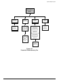
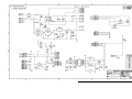
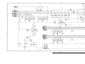
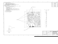
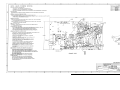
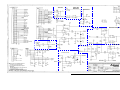
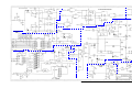
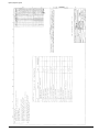
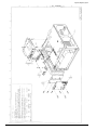
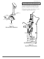
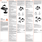
1
Return to the Browser Screen OPHTHALAS® 532 EYELITE® AND EYELASE* GREEN SERVICE MANUAL NOTE: This manual covers both the Ophthalas® 532 EyeLite® and the Eyelase* green lasers. These lasers are identical except for the labeling on the front and rear panels. All references to EyeLite® apply to both lasers unless noted otherwise. Alcon Surgical 15800 Alton Parkway Irvine, California 92618-3818 U.S.A. Telephone: 949/753-1393 800/832-7827 FAX: 949/753-6614 906-5420-501 D, PART NUMBER 906-5420-001 D, TEXT ONLY ©2001, 1999, 1998, 1997, Alcon Laboratories, Inc. EyeLite®/Eyelase green OPHTHALAS® 532 EYELITE® SERVICE MANUAL MANUAL REVISION RECORD DATE REVISION REVISED PAGE NUMBERS 05/97 A ECN # 32465- Initial Release 12/98 B ECN # 98200503 - i thru x, 1-1, 1-2, 1-4, 1-7, 1-9, 1-13, 2-1, 2-3, 2-5, 2-8 thru 2-10, 3-10, 51, 5-10, 5-12, 5-13, 5-16 thru 5-19, 5-21, 5-29, 6-1 thru 6-21, 7-1 thru 7-3, 7-5 thru 7-27, 8-1 thru 8-6, 8-9 thru 8-21, 8-23 thru 8-32 11/99 C ECN# 99201019 - i, ii, ix, 1-6, 5-1, 5-2, 5-4, 5-6, 5-16, 5-24, 5-25, 5-30 thru 5-32, 6-4 thru 6-6, 6-13, 6-19 thru 6-21, 7-9 thru 7-27, 8-10, 8-21 11/01 D ECN# 20013378 - Complete manual update. *EYELASE is a registered trademark of Aesculap Meditec GmbH **Zeiss is a registered trademark of Carl-Zeiss-Stiflung Keeler is a registered trademark of Keeler Optical Products Ltd. Nikon is a registered trademark of Nikon Inc. Corp. CSO is a registered trademark of Costruzione Strumenti Oftalmici S.R.L. Meditec is a registered trademark of Meditec Reinhardt Thysel GBMH Haag-Streit is a registered trademark of Haag-Streit AG Corporation ii 906-5420-501 EyeLite®/Eyelase green TABLE OF CONTENTS TOPIC PAGE # SECTION ONE - GENERAL INFORMATION Introduction . . . . . . . . . . . . . . . . . . . . . . . . . . . . . . . . . . . . . . . . . . . . . . . . . . . . . . . . . . . . . . . . . . . . . . . . 1-1 Description of this Manual . . . . . . . . . . . . . . . . . . . . . . . . . . . . . . . . . . . . . . . . . . . . . . . . . . . . . . . . . . . . . 1-1 Reference Documents . . . . . . . . . . . . . . . . . . . . . . . . . . . . . . . . . . . . . . . . . . . . . . . . . . . . . . . . . . . . . . . . 1-2 System Installation . . . . . . . . . . . . . . . . . . . . . . . . . . . . . . . . . . . . . . . . . . . . . . . . . . . . . . . . . . . . . . . . . . . 1-3 Warning Labels . . . . . . . . . . . . . . . . . . . . . . . . . . . . . . . . . . . . . . . . . . . . . . . . . . . . . . . . . . . . . . . . . . . . . 1-7 Front Panel Description . . . . . . . . . . . . . . . . . . . . . . . . . . . . . . . . . . . . . . . . . . . . . . . . . . . . . . . . . . . . . . . 1-8 Rear Panel Description . . . . . . . . . . . . . . . . . . . . . . . . . . . . . . . . . . . . . . . . . . . . . . . . . . . . . . . . . . . . . . 1-11 Informative Messages . . . . . . . . . . . . . . . . . . . . . . . . . . . . . . . . . . . . . . . . . . . . . . . . . . . . . . . . . . . . . . . 1-12 SECTION TWO - THEORY OF OPERATION Back Panel PCB . . . . . . . . . . . . . . . . . . . . . . . . . . . . . . . . . . . . . . . . . . . . . . . . . . . . . . . . . . . . . . . . . . . . . 2-1 Power Distribution . . . . . . . . . . . . . . . . . . . . . . . . . . . . . . . . . . . . . . . . . . . . . . . . . . . . . . . . . . . . . . . . . . . 2-3 CPU PCB . . . . . . . . . . . . . . . . . . . . . . . . . . . . . . . . . . . . . . . . . . . . . . . . . . . . . . . . . . . . . . . . . . . . . . . . . . 2-4 Interface PCB . . . . . . . . . . . . . . . . . . . . . . . . . . . . . . . . . . . . . . . . . . . . . . . . . . . . . . . . . . . . . . . . . . . . . . . 2-6 Analog PCB . . . . . . . . . . . . . . . . . . . . . . . . . . . . . . . . . . . . . . . . . . . . . . . . . . . . . . . . . . . . . . . . . . . . . . . . 2-8 Laser Head . . . . . . . . . . . . . . . . . . . . . . . . . . . . . . . . . . . . . . . . . . . . . . . . . . . . . . . . . . . . . . . . . . . . . . . . 2-10 Optics PCB . . . . . . . . . . . . . . . . . . . . . . . . . . . . . . . . . . . . . . . . . . . . . . . . . . . . . . . . . . . . . . . . . . . . . . . . 2-11 Front Panel PCB . . . . . . . . . . . . . . . . . . . . . . . . . . . . . . . . . . . . . . . . . . . . . . . . . . . . . . . . . . . . . . . . . . . 2-12 SECTION THREE - PARTS LOCATION & DISASSEMBLY General Information . . . . . . . . . . . . . . . . . . . . . . . . . . . . . . . . . . . . . . . . . . . . . . . . . . . . . . . . . . . . . . . . . . Disassembly Procedures . . . . . . . . . . . . . . . . . . . . . . . . . . . . . . . . . . . . . . . . . . . . . . . . . . . . . . . . . . . . . . 1 Removal of Top Cover . . . . . . . . . . . . . . . . . . . . . . . . . . . . . . . . . . . . . . . . . . . . . . . . . . . . . . 2 Installation of Top Cover . . . . . . . . . . . . . . . . . . . . . . . . . . . . . . . . . . . . . . . . . . . . . . . . . . . . 3 Removal of Handle . . . . . . . . . . . . . . . . . . . . . . . . . . . . . . . . . . . . . . . . . . . . . . . . . . . . . . . . . 4 Installation of Handle . . . . . . . . . . . . . . . . . . . . . . . . . . . . . . . . . . . . . . . . . . . . . . . . . . . . . . . 5 Removal of Front Panel Assembly . . . . . . . . . . . . . . . . . . . . . . . . . . . . . . . . . . . . . . . . . . . . . 6 Installation of Front Panel Assembly . . . . . . . . . . . . . . . . . . . . . . . . . . . . . . . . . . . . . . . . . . . 7 Disassembly of Front Panel Assembly . . . . . . . . . . . . . . . . . . . . . . . . . . . . . . . . . . . . . . . . . . 8 Assembly of Front Panel Assembly . . . . . . . . . . . . . . . . . . . . . . . . . . . . . . . . . . . . . . . . . . . . 9 Removal of Back Panel Assembly . . . . . . . . . . . . . . . . . . . . . . . . . . . . . . . . . . . . . . . . . . . . . 10 Installation of Back Panel Assembly . . . . . . . . . . . . . . . . . . . . . . . . . . . . . . . . . . . . . . . . . . . 11 Disassembly of Back Panel Assembly . . . . . . . . . . . . . . . . . . . . . . . . . . . . . . . . . . . . . . . . . . 12 Assembly of Back Panel Assembly . . . . . . . . . . . . . . . . . . . . . . . . . . . . . . . . . . . . . . . . . . . . 13 Removal of Power Supplies . . . . . . . . . . . . . . . . . . . . . . . . . . . . . . . . . . . . . . . . . . . . . . . . . . 14 Installation of Power Supplies . . . . . . . . . . . . . . . . . . . . . . . . . . . . . . . . . . . . . . . . . . . . . . . . 15 Removal of Pigtailed Fan Assembly . . . . . . . . . . . . . . . . . . . . . . . . . . . . . . . . . . . . . . . . . . . 16 Installation of Pigtailed Fan Assembly . . . . . . . . . . . . . . . . . . . . . . . . . . . . . . . . . . . . . . . . . 17 Removal of Analog PCB . . . . . . . . . . . . . . . . . . . . . . . . . . . . . . . . . . . . . . . . . . . . . . . . . . . . 18 Installation of Analog PCB . . . . . . . . . . . . . . . . . . . . . . . . . . . . . . . . . . . . . . . . . . . . . . . . . . 19 Removal of CPU PCB . . . . . . . . . . . . . . . . . . . . . . . . . . . . . . . . . . . . . . . . . . . . . . . . . . . . . . 20 Installation of CPU PCB . . . . . . . . . . . . . . . . . . . . . . . . . . . . . . . . . . . . . . . . . . . . . . . . . . . . 21 Removal of Interface PCB . . . . . . . . . . . . . . . . . . . . . . . . . . . . . . . . . . . . . . . . . . . . . . . . . . . 22 Installation of Interface PCB . . . . . . . . . . . . . . . . . . . . . . . . . . . . . . . . . . . . . . . . . . . . . . . . . 23 Removal of Optics PCB . . . . . . . . . . . . . . . . . . . . . . . . . . . . . . . . . . . . . . . . . . . . . . . . . . . . . 24 Installation of Optics PCB . . . . . . . . . . . . . . . . . . . . . . . . . . . . . . . . . . . . . . . . . . . . . . . . . . . 25 Removal of Optics Block . . . . . . . . . . . . . . . . . . . . . . . . . . . . . . . . . . . . . . . . . . . . . . . . . . . . 26 Installation of Optics Block . . . . . . . . . . . . . . . . . . . . . . . . . . . . . . . . . . . . . . . . . . . . . . . . . . 27 Removal of Motor/Shutter Assembly From Optics Block . . . . . . . . . . . . . . . . . . . . . . . . . . . 906-5420-501 3-1 3-1 3-1 3-1 3-2 3-2 3-2 3-2 3-2 3-3 3-3 3-3 3-3 3-4 3-4 3-4 3-4 3-4 3-4 3-5 3-5 3-5 3-6 3-6 3-6 3-6 3-6 3-6 3-7 iii EyeLite®/Eyelase green TABLE OF CONTENTS TOPIC PAGE # Disassembly Procedures (continued) 28 Installation of Motor/Shutter Assembly . . . . . . . . . . . . . . . . . . . . . . . . . . . . . . . . . . . . . . . . . 3-8 29 Removal of Aiming Diode From Optics Block . . . . . . . . . . . . . . . . . . . . . . . . . . . . . . . . . . . 3-8 30 Installation of Aiming Diode . . . . . . . . . . . . . . . . . . . . . . . . . . . . . . . . . . . . . . . . . . . . . . . . . 3-8 31 Removal of Laser Head . . . . . . . . . . . . . . . . . . . . . . . . . . . . . . . . . . . . . . . . . . . . . . . . . . . . . 3-8 32 Installation of Laser Head Assembly . . . . . . . . . . . . . . . . . . . . . . . . . . . . . . . . . . . . . . . . . . 3-10 SECTION FOUR - MAINTENANCE AND TROUBLESHOOTING Optical Alignment . . . . . . . . . . . . . . . . . . . . . . . . . . . . . . . . . . . . . . . . . . . . . . . . . . . . . . . . . . . . . . . . . . . 4-1 1 Laser Engine Inspection . . . . . . . . . . . . . . . . . . . . . . . . . . . . . . . . . . . . . . . . . . . . . . . . . . . . . 4-1 2 Laser Head Inspection . . . . . . . . . . . . . . . . . . . . . . . . . . . . . . . . . . . . . . . . . . . . . . . . . . . . . . 4-2 3 Inspection of the Optics Block . . . . . . . . . . . . . . . . . . . . . . . . . . . . . . . . . . . . . . . . . . . . . . . . 4-2 4 Fiber Alignment . . . . . . . . . . . . . . . . . . . . . . . . . . . . . . . . . . . . . . . . . . . . . . . . . . . . . . . . . . . 4-6 5 Delivered Power Calibration . . . . . . . . . . . . . . . . . . . . . . . . . . . . . . . . . . . . . . . . . . . . . . . . . 4-7 Calibration Procedure . . . . . . . . . . . . . . . . . . . . . . . . . . . . . . . . . . . . . . . . . . . . . . . . . . . . . . . . . . . . . . . 4-10 Adjustments . . . . . . . . . . . . . . . . . . . . . . . . . . . . . . . . . . . . . . . . . . . . . . . . . . . . . . . . . . . . . . . . . . . . . . . 4-12 Setting the Terminal Efficiencies . . . . . . . . . . . . . . . . . . . . . . . . . . . . . . . . . . . . . . . . . . . . . . . . . . . 4-12 Resetting the CPU PCB . . . . . . . . . . . . . . . . . . . . . . . . . . . . . . . . . . . . . . . . . . . . . . . . . . . . . . . . . . . 4-12 Setting the Keypad Illumination . . . . . . . . . . . . . . . . . . . . . . . . . . . . . . . . . . . . . . . . . . . . . . . . . . . . 4-13 Changing the System Parameters . . . . . . . . . . . . . . . . . . . . . . . . . . . . . . . . . . . . . . . . . . . . . . . . . . . 4-13 Troubleshooting . . . . . . . . . . . . . . . . . . . . . . . . . . . . . . . . . . . . . . . . . . . . . . . . . . . . . . . . . . . . . . . . . . . . 4-14 Error Messages Displayed on Front Panel . . . . . . . . . . . . . . . . . . . . . . . . . . . . . . . . . . . . . . . . . . . . 4-14 Laser Faults . . . . . . . . . . . . . . . . . . . . . . . . . . . . . . . . . . . . . . . . . . . . . . . . . . . . . . . . . . . . . . . . . . . . 4-15 Software Faults . . . . . . . . . . . . . . . . . . . . . . . . . . . . . . . . . . . . . . . . . . . . . . . . . . . . . . . . . . . . . . . . . 4-15 Hardware Errors . . . . . . . . . . . . . . . . . . . . . . . . . . . . . . . . . . . . . . . . . . . . . . . . . . . . . . . . . . . . . . . . 4-16 General Troubleshooting . . . . . . . . . . . . . . . . . . . . . . . . . . . . . . . . . . . . . . . . . . . . . . . . . . . . . . . . . . 4-17 Troubleshooting Trees . . . . . . . . . . . . . . . . . . . . . . . . . . . . . . . . . . . . . . . . . . . . . . . . . . . . . . . . . . . . 4-18 Test Point And LED Definitions . . . . . . . . . . . . . . . . . . . . . . . . . . . . . . . . . . . . . . . . . . . . . . . . . . . . 4-33 SECTION FIVE - SCHEMATICS Contents . . . . . . . . . . . . . . . . . . . . . . . . . . . . . . . . . . . . . . . . . . . . . . . . . . . . . . . . . . . . . . . . . . . . . . . . . . . 5-1 SECTION SIX - PARTS LISTS AND DRAWINGS Contents . . . . . . . . . . . . . . . . . . . . . . . . . . . . . . . . . . . . . . . . . . . . . . . . . . . . . . . . . . . . . . . . . . . . . . . . . . . 6-1 SECTION SEVEN - ADDITIONAL INFORMATION Slit Lamp Adaptations . . . . . . . . . . . . . . . . . . . . . . . . . . . . . . . . . . . . . . . . . . . . . . . . . . . . . . . . . . . . . . . . 7-1 Alcon SL1000 and Zeiss** 30SL Slit Lamp Adaptation . . . . . . . . . . . . . . . . . . . . . . . . . . . . . . . . . . . . . . 7-1 Haag-Streit Slit Lamp Adaptation . . . . . . . . . . . . . . . . . . . . . . . . . . . . . . . . . . . . . . . . . . . . . . . . . . . . . . . 7-8 Zeiss** SL130 Slit Lamp Adaptation . . . . . . . . . . . . . . . . . . . . . . . . . . . . . . . . . . . . . . . . . . . . . . . . . . . 7-13 Keeler Laser Indirect Ophthalmoscope (LIO) . . . . . . . . . . . . . . . . . . . . . . . . . . . . . . . . . . . . . . . . . . . . . 7-17 Alcon Laser Indirect Ophthalmoscope (LIO) . . . . . . . . . . . . . . . . . . . . . . . . . . . . . . . . . . . . . . . . . . . . . 7-19 EyeLite® to 3000LE Bridge . . . . . . . . . . . . . . . . . . . . . . . . . . . . . . . . . . . . . . . . . . . . . . . . . . . . . . . . . . . 7-22 Meditec Link for Zeiss** Slit Lamps . . . . . . . . . . . . . . . . . . . . . . . . . . . . . . . . . . . . . . . . . . . . . . . . . . . 7-26 Meditec Link for Haag-Streit Slit Lamps . . . . . . . . . . . . . . . . . . . . . . . . . . . . . . . . . . . . . . . . . . . . . . . . 7-30 iv 906-5420-501 EyeLite®/Eyelase green LIST OF ILLUSTRATIONS TITLE Figure 1-1 Figure 1-2 Figure 1-3 Figure 1-4 Figure 1-5 Figure 1-6 Figure 1-7 Figure 2-1 Figure 2-2 Figure 2-3 Figure 2-4 Figure 2-5 Figure 2-6 Figure 2-7 Figure 2-8 Figure 2-9 Figure 2-10 Figure 3-1 Figure 3-2 Figure 3-3 Figure 3-4 Figure 3-5 Figure 3-6 Figure 3-7 Figure 3-8 Figure 3-9 Figure 4-1 Figure 4-2 Figure 4-3 Figure 4-4 Figure 4-5 Figure 4-6 Figure 4-7 Figure 4-8 Figure 4-9 Figure 4-10 Figure 4-11 Figure 4-12 Figure 4-13 Figure 4-14 Figure 4-15 Figure 4-16 Figure 4-17 Figure 4-18 Figure 4-19 Figure 4-20 Figure 4-21 Figure 4-22 Figure 4-23 906-5420-501 PAGE # The Ophthalas® 532 EyeLite® Laser . . . . . . . . . . . . . . . . . . . . . . . . . . . . . . . . . . . . . . 1-1 Recommended Laser Room Layout (Overhead View) . . . . . . . . . . . . . . . . . . . . . . . . 1-3 Remote Connector/Door Lamp Circuit Diagram . . . . . . . . . . . . . . . . . . . . . . . . . . . . . 1-4 Warning Label Location Diagram . . . . . . . . . . . . . . . . . . . . . . . . . . . . . . . . . . . . . . . . 1-7 EyeLite® Front Panel . . . . . . . . . . . . . . . . . . . . . . . . . . . . . . . . . . . . . . . . . . . . . . . . . . 1-8 EyeLite® Display . . . . . . . . . . . . . . . . . . . . . . . . . . . . . . . . . . . . . . . . . . . . . . . . . . . . . 1-9 Rear Panel . . . . . . . . . . . . . . . . . . . . . . . . . . . . . . . . . . . . . . . . . . . . . . . . . . . . . . . . . . 1-11 System Block Diagram . . . . . . . . . . . . . . . . . . . . . . . . . . . . . . . . . . . . . . . . . . . . . . . . . 2-1 Back Panel PCB Block Diagram . . . . . . . . . . . . . . . . . . . . . . . . . . . . . . . . . . . . . . . . . 2-2 EyeLite® Power Distribution Block Diagram . . . . . . . . . . . . . . . . . . . . . . . . . . . . . . . 2-3 CPU PCB Connector Locations . . . . . . . . . . . . . . . . . . . . . . . . . . . . . . . . . . . . . . . . . . 2-4 Interface PCB Block Diagram . . . . . . . . . . . . . . . . . . . . . . . . . . . . . . . . . . . . . . . . . . . 2-7 Analog PCB Block Diagram . . . . . . . . . . . . . . . . . . . . . . . . . . . . . . . . . . . . . . . . . . . . 2-9 Optical Path Diagram . . . . . . . . . . . . . . . . . . . . . . . . . . . . . . . . . . . . . . . . . . . . . . . . . 2-10 Optics PCB Block Diagram . . . . . . . . . . . . . . . . . . . . . . . . . . . . . . . . . . . . . . . . . . . . 2-11 Front Panel PCB Block Diagram . . . . . . . . . . . . . . . . . . . . . . . . . . . . . . . . . . . . . . . . 2-13 EyeLite® Startup Process . . . . . . . . . . . . . . . . . . . . . . . . . . . . . . . . . . . . . . . . . . . . . . 2-14 Exploded View of the EyeLite® Laser . . . . . . . . . . . . . . . . . . . . . . . . . . . . . . . . . . . . . 3-1 Three Screws Securing Optics Block to Laser Head . . . . . . . . . . . . . . . . . . . . . . . . . . 3-6 Two Screws Securing Port Mounting Plate/Chimney to Optics Base Plate . . . . . . . . 3-7 Four Screws Securing Optics Base Plate to Optics Block Main Body . . . . . . . . . . . . 3-7 Two Screws Securing Motor/Shutter Assembly to Optics Block . . . . . . . . . . . . . . . . 3-7 Removal of Aiming Diode Assembly . . . . . . . . . . . . . . . . . . . . . . . . . . . . . . . . . . . . . 3-8 Six Screws Securing Laser Head to Chassis . . . . . . . . . . . . . . . . . . . . . . . . . . . . . . . . 3-9 Three Screws Securing Optics PCB Bracket to Chassis . . . . . . . . . . . . . . . . . . . . . . . 3-9 Location of Serial Number Used to Set the Laser Head Serial Number . . . . . . . . . . 3-10 Removing The Optics Block to Check Laser Engine Output . . . . . . . . . . . . . . . . . . . . 4-2 Removing Port Mounting Plate/Chimney from Optics Base Plate . . . . . . . . . . . . . . . 4-2 Removing Optics Base Plate from Main Body of Optics Block . . . . . . . . . . . . . . . . . 4-3 Replacement of The Aiming Diode Assembly . . . . . . . . . . . . . . . . . . . . . . . . . . . . . . . 4-3 Removing First Folding Mirror Assembly from Optics Block . . . . . . . . . . . . . . . . . . 4-3 Presetting The Mirror/Mounting Plate Gap . . . . . . . . . . . . . . . . . . . . . . . . . . . . . . . . . 4-4 Aligning The Aiming Beam . . . . . . . . . . . . . . . . . . . . . . . . . . . . . . . . . . . . . . . . . . . . . 4-4 Aligning The Surgical Beam . . . . . . . . . . . . . . . . . . . . . . . . . . . . . . . . . . . . . . . . . . . . 4-5 Aligning The Port Chimney . . . . . . . . . . . . . . . . . . . . . . . . . . . . . . . . . . . . . . . . . . . . . 4-5 Beam Size After Adjustments to Maximize Transmission . . . . . . . . . . . . . . . . . . . . . 4-6 Exposure Time Configuration . . . . . . . . . . . . . . . . . . . . . . . . . . . . . . . . . . . . . . . . . . . 4-7 Slit Lamp Power Configuration . . . . . . . . . . . . . . . . . . . . . . . . . . . . . . . . . . . . . . . . . . 4-7 Endoprobe Power Configuration . . . . . . . . . . . . . . . . . . . . . . . . . . . . . . . . . . . . . . . . . 4-7 LIO Power Configuration . . . . . . . . . . . . . . . . . . . . . . . . . . . . . . . . . . . . . . . . . . . . . . . 4-8 Location of Potentiometers PMON 1 & 2 . . . . . . . . . . . . . . . . . . . . . . . . . . . . . . . . . 4-10 Location of Potentiometers For Keypad Illumination Adjustment . . . . . . . . . . . . . . 4-13 Laser Fault 1 Troubleshooting Tree . . . . . . . . . . . . . . . . . . . . . . . . . . . . . . . . . . . . . . 4-18 Laser Fault 2 Troubleshooting Tree . . . . . . . . . . . . . . . . . . . . . . . . . . . . . . . . . . . . . . 4-18 Laser Fault 3 Troubleshooting Tree . . . . . . . . . . . . . . . . . . . . . . . . . . . . . . . . . . . . . . 4-18 Laser Fault 4 Troubleshooting Tree . . . . . . . . . . . . . . . . . . . . . . . . . . . . . . . . . . . . . . 4-19 Laser Fault 5 Troubleshooting Tree . . . . . . . . . . . . . . . . . . . . . . . . . . . . . . . . . . . . . . 4-20 Laser Fault 6 Troubleshooting Tree . . . . . . . . . . . . . . . . . . . . . . . . . . . . . . . . . . . . . . 4-21 Laser Fault 7 Troubleshooting Tree . . . . . . . . . . . . . . . . . . . . . . . . . . . . . . . . . . . . . . 4-21 v EyeLite®/Eyelase green LIST OF ILLUSTRATIONS TITLE Figure 4-24 Figure 4-25 Figure 4-26 Figure 4-27 Figure 4-28 Figure 4-29 Figure 4-30 Figure 4-31 Figure 4-32 Figure 4-33 Figure 4-34 Figure 4-35 Figure 4-36 Figure 4-37 Figure 4-38 Figure 4-39 Figure 4-40 Figure 4-41 Figure 4-42 Figure 4-43 Figure 4-44 Figure 4-45 Figure 4-46 Figure 6-1 Figure 6-2 Figure 6-3 Figure 7-1 Figure 7-2 Figure 7-3a Figure 7-3b Figure 7-3c Figure 7-4 Figure 7-5 Figure 7-6 Figure 7-7 Figure 7-8 Figure 7-9 Figure 7-10 Figure 7-11 Figure 7-12 Figure 7-13 Figure 7-14 Figure 7-15 Figure 7-16 Figure 7-17 Figure 7-18 Figure 7-19 Figure 7-20 Figure 7-21 Figure 7-22 vi PAGE # Cooling Fans Troubleshooting Tree . . . . . . . . . . . . . . . . . . . . . . . . . . . . . . . . . . . . . . 4-22 PMON1 & PMON2 Troubleshooting Tree . . . . . . . . . . . . . . . . . . . . . . . . . . . . . . . . 4-22 No Diode Current Troubleshooting Tree . . . . . . . . . . . . . . . . . . . . . . . . . . . . . . . . . . 4-23 Footswitch Troubleshooting Tree . . . . . . . . . . . . . . . . . . . . . . . . . . . . . . . . . . . . . . . . 4-24 Service Requested Troubleshooting Tree . . . . . . . . . . . . . . . . . . . . . . . . . . . . . . . . . . 4-25 Calibration Required Troubleshooting Tree . . . . . . . . . . . . . . . . . . . . . . . . . . . . . . . . 4-25 Cell 3 Detected Troubleshooting Tree . . . . . . . . . . . . . . . . . . . . . . . . . . . . . . . . . . . . 4-25 Connect Fiber Troubleshooting Tree . . . . . . . . . . . . . . . . . . . . . . . . . . . . . . . . . . . . . 4-26 Check Filter/Bridge Troubleshooting Tree . . . . . . . . . . . . . . . . . . . . . . . . . . . . . . . . 4-27 Aiming Beam Troubleshooting Tree . . . . . . . . . . . . . . . . . . . . . . . . . . . . . . . . . . . . . 4-28 Potentiometer Fault Troubleshooting Tree . . . . . . . . . . . . . . . . . . . . . . . . . . . . . . . . . 4-28 Shutter Fault Troubleshooting Tree . . . . . . . . . . . . . . . . . . . . . . . . . . . . . . . . . . . . . . 4-28 Laser Heat Fin Temperature Troubleshooting Tree . . . . . . . . . . . . . . . . . . . . . . . . . . 4-29 Hardware Error 1 (CRC) Troubleshooting Tree . . . . . . . . . . . . . . . . . . . . . . . . . . . . 4-30 Hardware Error 2 (Serial) Troubleshooting Tree . . . . . . . . . . . . . . . . . . . . . . . . . . . . 4-30 Hardware Error 3 (PMON) Troubleshooting Tree . . . . . . . . . . . . . . . . . . . . . . . . . . . 4-30 Hardware Error 4 (EPROM) Troubleshooting Tree . . . . . . . . . . . . . . . . . . . . . . . . . . 4-30 Hardware Error 5 (Startup) Troubleshooting Tree . . . . . . . . . . . . . . . . . . . . . . . . . . . 4-31 Hardware Error 6 (DA) and 10 (Timer) Troubleshooting Tree . . . . . . . . . . . . . . . . . 4-31 Hardware Error 7 (Memory) Troubleshooting Tree . . . . . . . . . . . . . . . . . . . . . . . . . . 4-31 Hardware Error 8 (CPU) Troubleshooting Tree . . . . . . . . . . . . . . . . . . . . . . . . . . . . . 4-31 Hardware Error 9 (Keyboard) Troubleshooting Tree . . . . . . . . . . . . . . . . . . . . . . . . . 4-31 Hardware Error 11 (Analog) Troubleshooting Tree . . . . . . . . . . . . . . . . . . . . . . . . . . 4-32 System Parts Breakdown . . . . . . . . . . . . . . . . . . . . . . . . . . . . . . . . . . . . . . . . . . . . . . . 6-3 Power Module . . . . . . . . . . . . . . . . . . . . . . . . . . . . . . . . . . . . . . . . . . . . . . . . . . . . . . . 6-4 Optics Block . . . . . . . . . . . . . . . . . . . . . . . . . . . . . . . . . . . . . . . . . . . . . . . . . . . . . . . . . 6-5 Alcon SL1000 Slit Lamp Assembly . . . . . . . . . . . . . . . . . . . . . . . . . . . . . . . . . . . . . . . 7-1 Zeiss** 30SL Slit Lamp Assembly . . . . . . . . . . . . . . . . . . . . . . . . . . . . . . . . . . . . . . . 7-2 Focal Point in Front of Target . . . . . . . . . . . . . . . . . . . . . . . . . . . . . . . . . . . . . . . . . . . 7-4 Focal Point Behind Target . . . . . . . . . . . . . . . . . . . . . . . . . . . . . . . . . . . . . . . . . . . . . . 7-4 Focal Point Properly Positioned On Target . . . . . . . . . . . . . . . . . . . . . . . . . . . . . . . . . 7-4 Lower Slits Mirror Adjustment . . . . . . . . . . . . . . . . . . . . . . . . . . . . . . . . . . . . . . . . . . 7-5 Upper Slits Mirror Adjustment . . . . . . . . . . . . . . . . . . . . . . . . . . . . . . . . . . . . . . . . . . . 7-5 Microscope Focus Adjustment . . . . . . . . . . . . . . . . . . . . . . . . . . . . . . . . . . . . . . . . . . . 7-6 1000 Micron Spot Focused on Graph Paper . . . . . . . . . . . . . . . . . . . . . . . . . . . . . . . . . 7-6 Spot is Perfectly Round on Wall . . . . . . . . . . . . . . . . . . . . . . . . . . . . . . . . . . . . . . . . . 7-6 Spot is Centered at all Sizes . . . . . . . . . . . . . . . . . . . . . . . . . . . . . . . . . . . . . . . . . . . . 7-7 50 Micron Aiming Spot Overlaps Slits . . . . . . . . . . . . . . . . . . . . . . . . . . . . . . . . . . . . 7-7 Micromanipulator Adjustments . . . . . . . . . . . . . . . . . . . . . . . . . . . . . . . . . . . . . . . . . . 7-8 Haag-Streit Slit Lamp Assembly . . . . . . . . . . . . . . . . . . . . . . . . . . . . . . . . . . . . . . . . . 7-8 Haag-Streit Slit Lamp Components . . . . . . . . . . . . . . . . . . . . . . . . . . . . . . . . . . . . . . . 7-9 1000 Micron Spot Focused On Graph Paper . . . . . . . . . . . . . . . . . . . . . . . . . . . . . . . 7-10 Spots Overlap Crosshairs . . . . . . . . . . . . . . . . . . . . . . . . . . . . . . . . . . . . . . . . . . . . . . 7-11 Spot is Clipped Evenly on All Four Sides . . . . . . . . . . . . . . . . . . . . . . . . . . . . . . . . . 7-11 Periscope . . . . . . . . . . . . . . . . . . . . . . . . . . . . . . . . . . . . . . . . . . . . . . . . . . . . . . . . . . . 7-11 Mirror Support . . . . . . . . . . . . . . . . . . . . . . . . . . . . . . . . . . . . . . . . . . . . . . . . . . . . . . 7-12 Micromanipulator . . . . . . . . . . . . . . . . . . . . . . . . . . . . . . . . . . . . . . . . . . . . . . . . . . . . 7-12 50 Micro Spot Overlaps Slits . . . . . . . . . . . . . . . . . . . . . . . . . . . . . . . . . . . . . . . . . . . 7-12 Zeiss** SL130 Slit Lamp and Adaptation . . . . . . . . . . . . . . . . . . . . . . . . . . . . . . . . . 7-13 Wireguide and Retainer . . . . . . . . . . . . . . . . . . . . . . . . . . . . . . . . . . . . . . . . . . . . . . . 7-14 906-5420-501 EyeLite®/Eyelase green LIST OF ILLUSTRATIONS TITLE Figure 7-23 Figure 7-24 Figure 7-25 Figure 7-26 Figure 7-27 Figure 7-28 Figure 7-29 Figure 7-30 Figure 7-31 Figure 7-32 Figure 7-33 Figure 7-34 Figure 7-35 Figure 7-36 Figure 7-37 Figure 7-38 Figure 7-39 Figure 7-40 Figure 7-41 Figure 7-42 Figure 7-43 Figure 7-44 Figure 7-45 Figure 7-46 Figure 7-47 Figure 7-48 Figure 7-49 906-5420-501 Split Prism Illuminator . . . . . . . . . . . . . . . . . . . . . . . . . . . . . . . . . . . . . . . . . . . . . . . . Zeiss** SL130 Adaptation . . . . . . . . . . . . . . . . . . . . . . . . . . . . . . . . . . . . . . . . . . . . . Adaptation Chimney With Fiber Cover Removed . . . . . . . . . . . . . . . . . . . . . . . . . . . The Keeler Laser Indirect Opthalmoscope . . . . . . . . . . . . . . . . . . . . . . . . . . . . . . . . . Honeycombed Illumination Image . . . . . . . . . . . . . . . . . . . . . . . . . . . . . . . . . . . . . . . The Alcon Laser Indirect Opthalmoscope . . . . . . . . . . . . . . . . . . . . . . . . . . . . . . . . . DVM Connection Point on EN20-1 Power Supply . . . . . . . . . . . . . . . . . . . . . . . . . . Position Grid Paper 300mm from Alcon LIO Reflecting Mirror . . . . . . . . . . . . . . . . Aiming Mirror Adjustment Screw . . . . . . . . . . . . . . . . . . . . . . . . . . . . . . . . . . . . . . . Alcon LIO Bulb Replacement . . . . . . . . . . . . . . . . . . . . . . . . . . . . . . . . . . . . . . . . . . EyeLite® to 3000LE Bridge . . . . . . . . . . . . . . . . . . . . . . . . . . . . . . . . . . . . . . . . . . . . 3000LE Fixation Lamp Removal . . . . . . . . . . . . . . . . . . . . . . . . . . . . . . . . . . . . . . . . CSO Headstrap Installation . . . . . . . . . . . . . . . . . . . . . . . . . . . . . . . . . . . . . . . . . . . . Interlock Connector On Base of 3000LE® . . . . . . . . . . . . . . . . . . . . . . . . . . . . . . . . . Bridge Cable Assembly . . . . . . . . . . . . . . . . . . . . . . . . . . . . . . . . . . . . . . . . . . . . . . . Meditec Link For Zeiss Slit Lamps . . . . . . . . . . . . . . . . . . . . . . . . . . . . . . . . . . . . . . Installation of Meditec Link . . . . . . . . . . . . . . . . . . . . . . . . . . . . . . . . . . . . . . . . . . . . Mounting Target to Headrest . . . . . . . . . . . . . . . . . . . . . . . . . . . . . . . . . . . . . . . . . . . Location of Screws for Vertical Adjustment. . . . . . . . . . . . . . . . . . . . . . . . . . . . . . . . Adjusting the Vario-Optics to Eliminate Spot Travel . . . . . . . . . . . . . . . . . . . . . . . . Adjusting the Spot Size . . . . . . . . . . . . . . . . . . . . . . . . . . . . . . . . . . . . . . . . . . . . . . . Meditec Link for Haag-Streit Slit Lamps . . . . . . . . . . . . . . . . . . . . . . . . . . . . . . . . . . Installation of the Meditec Link on a Haag-Streit Slit Lamp . . . . . . . . . . . . . . . . . . . Position of Focus Rod On Slit Lamp . . . . . . . . . . . . . . . . . . . . . . . . . . . . . . . . . . . . . Location of Screws For Vertical Adjustment. . . . . . . . . . . . . . . . . . . . . . . . . . . . . . . Adjusting the Vario-Optics to Eliminate Spot Travel . . . . . . . . . . . . . . . . . . . . . . . . Adjusting the Spot Size . . . . . . . . . . . . . . . . . . . . . . . . . . . . . . . . . . . . . . . . . . . . . . . PAGE # 7-14 7-16 7-16 7-17 7-18 7-19 7-19 7-21 7-21 7-22 7-23 7-24 7-24 7-25 7-25 7-26 7-27 7-28 7-28 7-29 7-29 7-30 7-31 7-32 7-32 7-32 7-33 vii EyeLite®/Eyelase green LIST OF TABLES TITLE Table 1-1 Table 1-2 Table 1-3 Table 1-4 Table 2-1 Table 2-2 Table 2-3 Table 2-4 Table 2-5 Table 2-6 Table 2-7 Table 2-8 Table 2-9 Table 2-10 Table 2-11 Table 4-1 Table 4-2 Table 4-3 Table 4-4 Table 4-5 Table 4-6 Table 6-1 Table 6-2 Table 6-3 viii PAGE # Technical Specifications . . . . . . . . . . . . . . . . . . . . . . . . . . . . . . . . . . . . . . . . . . . . . . . . 1-5 Laser Characteristics . . . . . . . . . . . . . . . . . . . . . . . . . . . . . . . . . . . . . . . . . . . . . . . . . . 1-5 EyeLite® Messages . . . . . . . . . . . . . . . . . . . . . . . . . . . . . . . . . . . . . . . . . . . . . . . . . . . 1-12 EyeLite® Prompts . . . . . . . . . . . . . . . . . . . . . . . . . . . . . . . . . . . . . . . . . . . . . . . . . . . . 1-13 CPU PCB Connector Definitions . . . . . . . . . . . . . . . . . . . . . . . . . . . . . . . . . . . . . . . . . 2-5 CPU PCB COM1 & COM2 Pinouts . . . . . . . . . . . . . . . . . . . . . . . . . . . . . . . . . . . . . . 2-5 Power Supply Connector Pinouts . . . . . . . . . . . . . . . . . . . . . . . . . . . . . . . . . . . . . . . . . 2-5 Analog PCB to Laser Head Signals . . . . . . . . . . . . . . . . . . . . . . . . . . . . . . . . . . . . . . 2-14 CPU PCB to Interface PCB (A2J3) Signals . . . . . . . . . . . . . . . . . . . . . . . . . . . . . . . . 2-14 Back Panel PCB to Interface PCB (A2J7) Signals . . . . . . . . . . . . . . . . . . . . . . . . . . . 2-14 Analog PCB to Interface PCB (A2J1) Signals . . . . . . . . . . . . . . . . . . . . . . . . . . . . . . 2-15 CPU PCB to Interface PCB (A2J2) Signals . . . . . . . . . . . . . . . . . . . . . . . . . . . . . . . . 2-16 Back Panel PCB to Interface PCB (A2J6) Signals . . . . . . . . . . . . . . . . . . . . . . . . . . . 2-17 Front Panel PCB to Interface PCB (A2J5) Signals . . . . . . . . . . . . . . . . . . . . . . . . . . 2-17 Optics PCB to Interface PCB (A2J4) Signals . . . . . . . . . . . . . . . . . . . . . . . . . . . . . . 2-18 Energy Matrix . . . . . . . . . . . . . . . . . . . . . . . . . . . . . . . . . . . . . . . . . . . . . . . . . . . . . . . . 4-9 Error Messages Displayed on the Front Panel . . . . . . . . . . . . . . . . . . . . . . . . . . . . . . 4-14 Laser Faults . . . . . . . . . . . . . . . . . . . . . . . . . . . . . . . . . . . . . . . . . . . . . . . . . . . . . . . . 4-15 Software Faults . . . . . . . . . . . . . . . . . . . . . . . . . . . . . . . . . . . . . . . . . . . . . . . . . . . . . . 4-15 Hardware Errors . . . . . . . . . . . . . . . . . . . . . . . . . . . . . . . . . . . . . . . . . . . . . . . . . . . . . 4-16 General Troubleshooting . . . . . . . . . . . . . . . . . . . . . . . . . . . . . . . . . . . . . . . . . . . . . . 4-17 System Parts List . . . . . . . . . . . . . . . . . . . . . . . . . . . . . . . . . . . . . . . . . . . . . . . . . . . . . 6-2 Power Module (542-1150-001) Parts List . . . . . . . . . . . . . . . . . . . . . . . . . . . . . . . . . . 6-4 Optics Block (542-1018-501) Parts List . . . . . . . . . . . . . . . . . . . . . . . . . . . . . . . . . . . . 6-5 906-5420-501 EyeLite®/Eyelase green SECTION ONE GENERAL INFORMATION INTRODUCTION This manual covers both the Ophthalas® 532 EyeLite® and the Eyelase green lasers. These lasers are identical except for the labeling on the front and rear panels. All references to EyeLite® apply to both lasers unless noted otherwise. The EyeLite® is a Neodymium-doped Yttrium Aluminum Garnet (ND: YAG) type laser which has been designed for ophthalmic use. LASER is an acronym for “Light Amplification by Stimulated Emission of Radiation.” This laser delivers a visible 532 nm green laser beam (frequency doubled), and a visible 670 nm Diode Laser aiming beam (670 nm is an approximate value between 660-680 nm). DESCRIPTION OF THIS MANUAL The purpose of this manual is to provide the field engineer with the necessary information to maintain and repair the EyeLite® system. This manual is divided into eight sections as follows: Section One-General Information This section describes how to install the EyeLite®, and gives a general description of the EyeLite® features and components. Section Two-Theory of Operation This section gives a detailed description of how the EyeLite® operates starting at the system level and working down to the PCB (Printed Circuit Board) level. Section Three-Parts Location and Disassembly This section contains parts location diagrams along with field level disassembly procedures for the EyeLite® console. Disassembly procedures for OEM (Original Equipment Manufacturer) components are considered the property of the manufacturer and are not provided in this manual. Section Four-Maintenance & Troubleshooting This section contains system maintenance procedures and troubleshooting information along with listings of spares, tools, and supplies required to repair the system. Section Five-Schematics This section contains the system interconnect diagrams, PCB assembly, and schematic drawings. Section Six-Parts Lists and Drawings This section contains parts lists, cable drawings, and engineering documentation for each major assembly. Figure 1-1 The OPHTHALAS® 532 EyeLite® Laser 906-5420-501 1-1 EyeLite®/Eyelase green Section Seven-Additional Information This section contains miscellaneous information pertaining to this system. REFERENCE DOCUMENTS Although this manual provides the necessary information for maintaining optimum performance of the EyeLite®, it does not contain all of the operating procedures or functional descriptions contained in the Operator's Manual. In addition, the Warnings and Cautions in the Operator's Manual also apply for this Service Manual. The Operator's Manual supplements information provided in this manual and should be available on-site with the system. If you have any questions or require additional information, please contact your local Service Representative or the Technical Services Department at: ALCON SURGICAL 15800 Alton Parkway Irvine, CA 92618-3818 (949) 753-1393 (800) 832-7827 If you are located outside the United States, please contact your local authorized Alcon representative. CAUTION Federal (U.S.A.) law restricts this device to sale by or on the order of a physician. 1-2 906-5420-501 EyeLite®/Eyelase green General Safety Precautions (Refer to IEC 825-1 or ANSI Z136.1) • A laser safety officer should be appointed to supervise the installation and use of the system. SYSTEM INSTALLATION The system was inspected mechanically and electrically prior to shipment. If shipping boxes appear damaged, ask that the carrier’s agent be present when system is unpacked. Inspect system for external damage (i.e. scratches, dents, or broken parts). If damage is discovered or if system fails any of the functional tests notify the carrier and an Alcon Surgical representative. Retain shipping boxes and packing material for carrier’s inspection. As necessary, file a claim with carrier or, if insured separately, with insurance company. • Install an indicator light outside the laser room warning of instrument operation. • Position the instrument so that the laser beam is never directed toward a door, window or reflective surface. • Use a non-reflective matte finish wall paint. • Avoid covering laser room floor and walls with carpet or any other dust generating material. This will minimize the possibility of excess grime and dust on the instrument optics, and interference with equipment cooling. • The instrument requires a minimum of 0.5 meter of open space on all sides for proper cooling ventilation. Therefore, the system should be set flat, resting on the legs provided on the bottom of the console. • Unauthorized use of this laser should be prevented by key removal. NOTE: When unpacking a demonstration system, save boxes for repacking. General Laser Room Layout The EyeLite® must be installed in a dust-free room, and positioned so the laser beam cannot be directed toward a door, window, mirror, or reflective area. To reduce dust, avoid installing the instrument in a carpeted room. An example of a typical laser room layout is shown in Figure 1-2. Slit Lamp and Table - Emission Zone Limited access. Avoid doors, windows, mirrors, reflective surfaces. Table (shown for illustrative purposes only) 1 meter minimum 1 meter (40") minimum EyeLite® Console 0.5 meter minimum Figure 1-2 Recommended Laser Room Layout (Overhead View) 906-5420-501 1-3 EyeLite®/Eyelase green • Entrances to areas or protective enclosures containing Class IV lasers should be posted with appropriate warning signs. • Appropriate eye protection must be used in all hazard areas. Use eye protection with OD 4 or above at 532 nm. • A qualified technician must verify that the power plug used is properly grounded. • The remote interlock connector should be connected to an emergency master disconnect interlock or to room/door/fixture interlocks. Please refer to Figure 1-3. REMOTE CONNECT 2 CAUTION Before turning the instrument ON for the first time after receipt of the system, wait one hour for the components and optics to normalize to avoid possible condensation that may have occurred during shipping. Use only <HAR> power cord with a minimum of 10 Amp rating. Before connecting the main plug verify that: • The Main Switch on the back panel is in the OFF (O) position. • The key is in the OFF (vertical) position, or has been removed. • The Remote Plug is connected on the Rear Panel. CUSTOMER SUPPLIED DOOR SWITCH (OPTIONAL) 8 9-PIN D-CONNECTOR 9 1 Electrical Connections TO DRIVE DOOR LAMP (OPTIONAL) Figure 1-3 Remote Connector/Door Lamp Circuit Diagram Optical Connections Optical connections vary in relation to the procedure to be performed. Different peripherals can be connected to the output port. These peripherals are: • Slit Lamp adaptation • Laser Indirect Ophthalmoscope • Endoprobe/Aspirating Probe The procedures for connecting these peripherals are contained in the Operator's Manual. Utility Requirements: Electrical requirement: The EyeLite® has an autoranging power supply which operates at 100-120 V and 220-240 V input ranges at 50/60 Hz. A properly grounded, standard plug is the only requirement. 1-4 906-5420-501 EyeLite®/Eyelase green Table 1-1 Technical Specifications CATEGORY Approximate Dimensions Approximate Weight Electrical Characteristics SPECIFICATION Width: 0.38 m (15.30 inches) Length: 0.45 m (17.75 inches) Height: 0.23 m (9.10 inches) 16.4 Kilos (36 lbs.) Voltage: 100-120 VAC/220-240 VAC Frequency: 50/60 Hz Fuse rating: 250V,Single Phase 6.3 Amps Insulation class: Class I, type BF, Intermittent use: 50% Duty cycle Operating: Temperature: 15° C ≤ T° ≤ 35° C Relative Humidity:10% to 90% with no condensation Storage: Temperature: -40° C ≤ T° ≤ 70° C Relative Humidity:10% to 90% with no condensation Environmental Limitations EyeLite complies with CE MDD requirements. Not suitable for use in the presence of flammable anesthetic, oxygen or nitrous oxide. Miscellaneous System not protected against the ingress of water. Leakage current per IEC 601-1 is below 500 micro amps. Ground continuity per IEC 601-1 is below 0.1 ohm. Table 1-2 Laser Characteristics CATEGORY TREATMENT LASER BEAM AIMING LASER BEAM Laser Class IV II • 30mW to 100mW in 10mW steps Laser Power • 100mW to 1W in 20mW steps with additional steps at: 0.15, 0.25, 0.35, 0.45, 0.55, 0.65, 0.75, 0.85, 0.95 1mW maximum; adjustable by operator • 1W to 1.7W (minimum) in 100mW steps Laser Wavelength 906-5420-501 532 nm approximately 670 nm 1-5 EyeLite®/Eyelase green CAUTION Canadian approval requires this supply system to be a balanced, single-phase, two-pole system. Leakage exceeds 100 mA in an unbalanced system. EMC Statement: This equipment has been tested and found to comply with the limits for medical devices as specified in IEC 601-1-2:1993, EN60601-1-2:1994 and Medical Device Directive 93/42/EEC. These limits are designed to provide reasonable protection against harmful interference in a typical medical installation. Universal Precautions: Universal precautions shall be observed by all people who come in contact with the instrument and/or accessories to help prevent their exposure to blood-borne pathogens and/or other potentially infectious materials. In any circumstance, wherein the exact status of blood or body fluids/tissues encountered are unknown, it shall be uniformly considered potentially infectious and handled in accordance with OSHA guidelines. It is important to install and use the equipment in accordance with the instructions to prevent harmful interference to other devices in the surrounding area. You can determine whether or not the device is causing interference by turning it off and checking to see if the problem still exists. If this equipment does cause harmful interference to other devices, the user is encouraged to correct the interference by one or more of the following measures: • Reorient or relocate the other device(s). • Increase the separation between the equipment. • Connect this equipment into an outlet on a circuit different from that to which the other device(s) are connected. • Consult the manufacturer or authorized field service technician for help. Environmental Issues: Follow local governing ordinances and recycling plans regarding disposal or recycling of device components. 1-6 906-5420-501 DANGER Laser Yag x2 532nm - 3.5W DIODE LASER 660-680nm - 1mW LASER YAG x 2 532 nm - 3.5W - CW DIODE LASER 660-680 nm - 1mW CLASS 4 LASER PRODUCT IEC 825 - A1:1990, 601-1:1988 DANGER 542-1104-001 REV* Visible laser radiation. Avoid eye or skin exposure to direct or scattered radiation. 542-1053-001 REV* LASER RADIATION AVOID EYE OR SKIN EXPOSURE TO DIRECT OR SCATTERED RADIATION CLASS 4 LASER PRODUCT RISQUE D'EXPLOSION SI UTILISATION EN PRESENSE D'ANESTHETIQUE INFLAMMABLE 542-1051-001 REV* RAYONNEMENT LASER EXPOSITION DANGEREUSE DE L'OEIL OU DE LA PEAU AU RAYONNEMENT DIRECT OU DIFFUS APPAREIL A LASER DE CLASSE 4 532-1208-001 REV* EyeLite®/Eyelase green POSSIBLE EXPLOSION HAZARD IF USED IN THE PRESENCE OF FLAMMABLE ANAESTHETIC Class IV laser product A B L'USAGE DE CE LASER SANS FILTRE MEDECIN PEUT ENDOMAGER LES YEUX DE L'UTILISATEUR T6.3AH 250V E F for EyeLite ® 542-1054-001 REV* WARNING * 532-1394-001 REV USE OF THIS LASER WITHOUT A SAFETY FILTER MAY RESULT IN DAMAGE TO THE OPERATOR'S EYES D C G * LATEST LABEL REVISION MUST BE PLACED IN THIS POSITION. F for Eyelase green C A DR's FILTER IPX8 B EXPANSION D OPH T S E HAL ® R P AS H SERVICE 24V/1AMP G REMOTE POWER ON E DISPLAY LIGHT VOLUME F LA OT OC 532 E y OA GU eLite™ LA TO R Rear Panel Figure 1-4 Warning Label Location Diagram 906-5420-501 1-7 EyeLite®/Eyelase green FRONT PANEL DESCRIPTION C - Exposure Time Display The Front Panel, shown in Figure 1-5, allows the operator to control, change settings, and monitor the EyeLite®. Changes to the current system setup are acknowledged by a beep. For example: if the terminal selection or power is changed, the system will beep. A liquid crystal display shows operational prompts and error messages. An arrangement of four, 7-segment LEDs that displays the selected exposure time in seconds. The exposure time is adjusted by the Exposure Time Adjustment Keys. In Continuous Wave mode, all displays show dots (...). A - Emergency Switch Depressing the Emergency Switch causes all functions, including the laser power supply, to shut down. To restore power, pull the Emergency Switch to the out position. B - Emergency Switch Indicator LED This indicator illuminates to warn the surgeon when the Emergency Switch has been depressed to shutdown the system. Pulling the Emergency Switch to the out position extinguishes this LED. D - Exposure Time Adjustment Keys These up and down arrow keys allow the user to adjust the duration of the exposure time. The default setting for exposure time is 0.2 s. The exposure time can be adjusted to the following values by these two keys: 0.01 - 0.02 - 0.05 - 0.1 - 0.15 - 0.2 - 0.25 - 0.3 - 0.4 - 0.5 - 0.7 - 1 - 1.5 - 2.0 - CW NOTE: In CW (Continuous Wave) mode, depending on the thermal load of the system, the EyeLite® may shut down prior to the footswitch being released. A message on the LCD display will indicate this condition. Therefore, it is not recommended to use exposure times longer than 2 seconds in CW mode. Figure 1-5 EyeLite® Front Panel 1-8 906-5420-501 EyeLite®/Eyelase green E - Standby/Ready Switch I - Repeat Mode Selection Key The Standby/Ready Switch allows the user to select either Standby or Ready mode. Each mode has a corresponding LED - Green for Standby and Red for Ready - to indicate the current selection. The Ready mode must be selected in order for laser treatment to proceed. Repeat mode is selected by pressing the Repeat Mode Selection Key for at least two seconds. The two second delay serves to avoid any non-intentional setup. The LED above this key illuminates when the system is in repeat mode. The interval time between each shot in repeat mode is displayed on the LCD. F - Reset Key A single press of the Repeat key returns the system to single shot mode (one exposure time per footswitch depression determined by the exposure time selection). Pressing the Reset Key resets the laser exposure counter displayed on the LCD back to 0. The maximum number is 9999 shots. G - Interpulse Time Adjustment Keys For Repeat Mode These up and down arrow keys allow the user to adjust the interval time between exposure times in repeat mode. The default value is set to 300 ms and is adjusted by these two keys from 100 ms to 1000 ms in 100 ms increments. J - Confirm Key The Confirm Key allows the surgeon to respond to a system prompt which is displayed on the LCD during a procedure. Pressing the Confirm key represents a positive reply to a prompt. The system stays in the pending mode until a confirmation is given by the operator. H - LCD Display K - Key Indicator The LCD display is the communication interface between the surgeon and the system. It advises the surgeon as to the state of the system with the following information: the Terminal selected, the Mode configuration, the Shot Count, and Prompts/Messages. The Key Indicator illuminates when the key is turned to the ON position. 1. Terminal: LIO 2. Mode: Repeat 400 ms 3. Shot Count: 58 4. Prompts/Messages Figure 1-6 EyeLite® Display 1. Terminal selected corresponds with the selection made by the operator using the Terminal Selection key. 2. Indicates single shot or repeat mode selection with the interpulse time. 3. Counter contains the number of shots. 4. Each prompt must be confirmed by depressing the Confirm key. Each message informs the operator of the current system status. 906-5420-501 L - Keyswitch The keyswitch is a two-position switch where the key can be removed only in OFF position. In the OFF position, the main power to the system is shut off. In the ON position, an orange LED is illuminated. M - Laser Aperture An SMA connector with a fiber safety connection is provided to connect the EyeLite® to the desired delivery system (terminal); i.e., Slit Lamp adaptation, Laser Indirect Ophthalmoscope (LIO), or Endoprobe/ Aspirating probe. When the fiber is disconnected, a message is displayed on the LCD. 1-9 EyeLite®/Eyelase green N - Laser ON/OFF Switch • The system powers up with this switch ON. In this position the laser could be operational depending upon the next keystroke(s). • When the switch is OFF, both lasers are OFF, the cooling system is powered, and the LCD alerts the surgeon that the system is in this mode. • When the switch is turned ON again, the system goes back to the default value, and the terminal selection is the Slit Lamp. Q - Aiming Beam Intensity Knob This knob is attached to a potentiometer which adjusts the intensity of the aiming beam. The computer adjusts the intensity limits depending upon the delivery system selected; therefore, at a given position the output intensity could be different from one delivery system selection to another. The knob travels through 270° of rotation with minimum output in the farthest counterclockwise position and maximum output in the farthest clockwise position. R - Power Adjust Knob O - Terminal Selection LEDs When the desired terminal is selected, the LED that corresponds to the selected terminal illuminates. P - Terminal Selection Key The Terminal Selection Key allows the user to select one of the following terminals for operation: Slit Lamp Adaptation, Laser Indirect Ophthalmoscope (LIO) or Endoprobe/Aspirating probe. The selection "OTHER" is not enabled. A selection is made by pressing and holding the Terminal Selection Key until the LED representing the desired terminal illuminates. When switching from one terminal to another, a prompt is displayed on the LCD which requires confirmation by pressing the Confirm key. The power is adjusted by turning this knob which is attached to a three-turn potentiometer. If the potentiometer is not in the minimum position after the initial setup time, a warning message prompting the user to turn it to the minimum position is displayed on the LCD. The following power settings are available for the listed delivery systems: 0.03W - 1.7W (minimum) Slit Lamp 0.10W - 1.7W (minimum) LIO 0.05W - 1.7W (minimum) Endo/Aspirating Probe. If the operator turns this knob too fast, a safety shutdown occurs as the system detects an invalid control command and displays the following message: “Potentiometer Fault”. S - Power Indicator The Power Indicator is an arrangement of four, 7segment LEDs that shows the output power (in Watts) at the cornea. 1-10 906-5420-501 EyeLite®/Eyelase green REAR PANEL DESCRIPTION E - Power Entry Module A - Doctor’s Filter Connection The main power cord is connected to the plug connector on the device with the necessary fuse to comply with electrical regulations. When the main power cord is connected and the power switch is turned on, an LED on the back panel illuminates. The Doctor’s Filter (for Slit Lamp and Endoprobe) is connected to this port. If the Doctor’s Filter is not engaged, firing cannot occur and the message “Engage Dr’s filter” is displayed on the LCD. F - Remote Interlock Connection B - Footswitch Connection The Remote Interlock Connection permits the facility to connect a door-activated switch to the EyeLite® system. The footswitch controls delivery of the treatment laser beam and is connected to the system through this port. A relay closure rated at 24 VDC, 1 amp is provided to comply with CE regulations. When the Remote Interlock is activated, the surgeon is warned by a message displayed on the LCD (Laser Fault 07) and the lasers are turned off. Clear the Remote Interlock and reset the system by turning the EyeLite® key OFF then ON. D - Service Connector G - Volume Adjustment Knob The Alcon Field Engineer can access the system by connecting a computer to this port. A password is required to gain access to the system and this procedure can only be performed by qualified personnel. Provision for future applications. C - Relay Contact H - Display Light Adjustment Knob The LCD backlighting intensity is adjusted by turning this knob. WARNING! Never use the EyeLite® for treatment when connected to a computer or any other device. I - Expansion Connector Provision for future connections. Figure 1-7 Rear Panel 906-5420-501 1-11 EyeLite®/Eyelase green INFORMATIVE MESSAGES The messages listed in Table 1-3 are displayed on the LCD display to inform the operator of system status. Table 1-3 EyeLite® Messages MESSAGE Alcon 532 EyeLite XX Represents the version of software in the system. Please Wait During the initial warm-up sequence, the LEDs flash for 8 seconds, and during transition from standby to ready for 2 seconds. System Start-up Start-up procedure. Mode: Single Shot When the system is in Ready mode with the Single Shot selection, an action on the footswitch delivers one shot per exposure time selected. If the footswitch is released prior to the termination of the exposure time, the treatment beam is interrupted. Mode: Continuous When the system is in Ready mode with the Continuous selection, an action on the footswitch delivers the beam until the footswitch is released. Mode: Repeat XXX ms XXX represents the interval time which can be selected. The range is 100ms to 1000ms in 100ms increments (default is 300ms). Shot Count: XXXX XXXX represents the number of shots. This can be reset to 0 by pressing the reset key, pressing the laser off button, activating the emergency switch or power off, or turning the keyswitch off. Lasers OFF When the OFF key is pressed, both lasers shut-down. Terminal Slit Lamp The operator has selected and confirmed the Slit Lamp terminal. Terminal LIO The operator has selected and confirmed the LIO terminal. Terminal Endo The operator has selected and confirmed the Endo terininal. LIO Term Selected This message flashes for 3 seconds to alert the operator that this selection has been made. Power not in range Power is not within ±20% before treatment. OFF Condition Treatment has been interrupted since the power is not within ±20%. *------------------- 1-12 DESCRIPTION Laser emission is occurring. 906-5420-501 EyeLite®/Eyelase green The prompts listed in Table 1-4 are displayed on the LCD display when action is required by the operator. Table 1-4 EyeLite® Prompts PROMPT Connect Fiber The system has detected that the fiber is not connected to the Laser Aperture SMA connector on the front panel. The system will stay in this mode until the connection is made. Set power to minimum The system has detected that the treatment power is not set to the minimum setting. For safety reasons, the system will stay in this mode until the Power Adjust knob is turned fully counterclockwise to the minimum setting. Release Footswitch The system has detected that the footswitch is depressed during warm-up or while transitioning from standby to ready. In order for the system to proceed, the footswitch must be released. Engage Dr's filter The system has detected that the Dr. Filter is not engaged. The system will remain in standby until the Dr. Filter is engaged. Check Filter/Bridge The system detected that either the Dr. Filter or the Bridge (3000LE™*) has not been connected or properly engaged. The system will remain in Standby mode until the connection is made. Check Filter1 1 DESCRIPTION Select Slit Lamp? The Slit Lamp Terminal is selected. Pressing the confirm key sets the system for use with this terminal. Select LIO Term? The LIO Terminal is selected. Pressing the confirm key sets the system for use with this terminal. Select Endo Term? The Endo Terminal is selected. Pressing the confirm key sets the system for use with this terminal. Dr. Filter in place? The Dr. Filter must be properly in place on the Slit Lamp or Microscope to protect the Doctor during treatment. Displayed on Eyelase green. 906-5420-501 1-13 EyeLite®/Eyelase green THIS PAGE INTENTIONALLY BLANK 1-14 906-5420-501 EyeLite®/Eyelase green SECTION TWO THEORY OF OPERATION The purpose of this section is to provide general information regarding how certain PCB's and circuits operate and the functions they are responsible to perform. This section is not intended to provide an indepth, component-level analysis of the system. Voltage and/or signal analysis can be performed by analyzing the schematics for the PCB’s manufactured by Alcon. Theory of operation and schematics for OEM products used in the EyeLite® remain the property of the respective manufacturers. voltage goes through a step down transformer and is reduced to 20V. This 20V signal is rectified by BR1 and regulated down to 12VDC. This 12V signal is sent to the green LED at the rear of the system and is then routed through the Front Panel PCB to check the status of the key switch. If the key switch and Emergency switch are properly set, the 12V signal is sent to energize K1 and power up the rest of the circuits. DC Power The Back Panel PCB receives ±12V and +5V from the Analog PCB through J6. These signals are processed and sent out to other PCB's used in the EyeLite. ±12V and +5V are sent to the CPU (Microprocessor) and Interface PCB’s through J10. Part of the -12V is regulated down to -5V (U1) and then sent to the Interface PCB along with the ±12V and +5V through J10. Figure 2-1 is a block diagram which shows a simplified overview of the system. Following this diagram, each block is discussed in detail with an associated detailed diagram of the block. Refer to Tables 2-4 through 2-11 at the end of this section for descriptions of PCB interconnections. Filtered DC Power The 5V signal received from the Analog PCB is amplified by a DC to DC converter to ±12V. This signal is designated by ±12VA. This ±12V is used to provide a clean (relatively noise free) ±12 volt signal to the analog devices of the Interface PCB (J1). BACK PANEL PCB (see Figure 2-2) The Back Panel PCB consist of several circuits designed to provide an interface between the outside devices and the laser system. A secondary function is to provide power for certain PCB’s and devices. Power Entry Module Power is received via the line source and processed in the Power Entry Module. The line voltage is then filtered through L3 and splits at this point. The first part of the voltage is sent to relay K1. When K1 is energized, it will send voltage to the power supplies. The other part of the Fan Fan ANALOG PCB LASER POWER SUPPLY 120/240 V OPTICS BLOCK LASER HEAD diode drive Laser Cavity Head PCB laser beam laser & aiming beams pmon REAR PANEL PCB POWER ENTRY MODULE RS232 Service Port This is a standard RS232 port. The connection to COM1 of the CPU PCB is made directly to this port. The expansion port is also a RS232 port, however, at this time it is not used. Aiming Beam control ELECTRONICS POWER SUPPLY drive signals distributed to system via Analog & Rear Panel PCBs detect signals control data INTERFACE PCB OPTICS PCB data control CPU PCB display data data FRONT PANEL PCB serial communication Figure 2-1 System Block Diagram 906-5420-501 2-1 EyeLite®/Eyelase green Interlock The Interlock circuitry resides on the Analog PCB. The interlock connection is typically connected to switch located near a door in such a manner that opening and closing the door will operate the switch. The wires from the switch are connected to the interlock plug at pins 2 and 8. With the interlock plug connected and the door switch closed, the signal from the Analog PCB is pulled low. This originates from a relay. When the door is opened or the plug removed, the circuit on the Analog PCB is pulled high, the laser is disabled, and the interlock error signal is sent to the Interface PCB. Doctor's Filter The Doctor's filter circuit serves two purposes. Pins 1, 3, and 5 are used to monitor the micro switches of the Doctor's filter. These signals are routed directly to the Interface PCB. These signals are designated DRF1_1, DRF1_3, and DRF1_5. DRF1_CTRL is a buffered 5V analog signal from the Interface PCB. This signal is amplified by U4 and sent to Pin 6 however it is not currently used. There are provisions and circuits for a second Doctor's filter (U3) included as well, and are not used at this time. OTHER CIRCUITS Footswitch When the footswitch is depressed, FS_NC is high (+12V) and indicates to the Interface PCB that the footswitch is depressed. This +12V comes from the Optics PCB via J7. FS_NO is pulled low under the same conditions. When the footswitch is not depressed, FS_NO is high (+12V) and indicates to the Interface PCB that the footswitch is connected to the EyeLite. Laser On This circuit is used to activate an external warning lamp. When the EyeLite® is in the Ready mode the LZRDY signal is used to energize relay K2. When K2 is energized, power to activate an external relay is connected. Key Switch Panic Switch Back Panel PCB Power Entry Module Line Filter Transformer/ Rectifier To Interface PCB Back-Lite Control AC Mains Power Cord Volume Control AC Relay +5V From Analog PCB Amplifier and Filter Inverter To Power Supplies +12VA -12VA To Interface PCB -5V +5V +12V To CPU, Interface, and Back Panel PCB's -12V To Optics PCB To Interface PCB To Analog PCB To CPU PCB Footswitch Dr's Filter Connector Remote Interlock Switch Expansion RS232C Com Port 24V 1 Amp Relay connector From Analog PCB Dr's Filter N/C Interlock Plug AMP Footswitch Connector Service Computer Relay Connector Figure 2-2 Back Panel PCB Block Diagram 2-2 906-5420-501 EyeLite®/Eyelase green LZON Signal This signal is generated by the Analog PCB indicating that the laser is set to fire. It is routed to the Optics PCB by J7. A low signal indicates that the laser is ready. POWER DISTRIBUTION (Figure 2-3) Volume and Message Control The +5V buffered signal is sent to two potentiometers via J1 pin 31. R24 controls the message panel display and R23 controls the volume. The volume function is not currently used. The power supply module consists of two switching power supplies piggy-backed together. The upper supply is the Electronics Power Supply and supplies the necessary +12, -12, +5 V to run the circuit boards. Its output is connected to the Analog PCB. The lower power supply is the Laser Power Supply which drives the laser diode and head TEC (thermo electric cooler). It provides -3.3 V at up to 38 amps for the laser diode, and 12 V for the TEC. Attached to the Laser Power Supply is a solid state relay that interrupts the 120/240 V input when it is determined that the laser head should be shut off. The Laser Power Supply has a 5A 250V fuse on the input and the Electronics Power Supply has a 2A 250V fuse. Both fuses are of the T20 variety. 120/240 VAC From Back Panel PCB Electronics Power Supply Solid State Relay Laser Power Supply Analog PCB Back Panel PCB To Laser Head and TEC via Analog PCB To CPU and Interface PCB's Power Supply Fan Heatsink Fan (variable) Figure 2-3 EyeLite® Power Distribution Block Diagram 906-5420-501 2-3 EyeLite®/Eyelase green CPU PCB This OEM PCB (see Figure 2-4) is used to run a program designed by Alcon to control the EyeLite® laser. The code necessary to run the EyeLite® is transferred to the Interface PCB through the Synchronous Expansion Bus (SEB) in digital form. The SEB is the main communication port for the EyeLite®. CPU specifications are as follows: • Intel386 EX processor. • Intel 4 Mbyte Boot Block Flash, which contains a flash programming/loader utility. • Bus/Memory Controller ASIC. • PCMCIA Slot. • Pipelined, zero wait state, page mode operation. • Non-pipelined, one wait state, page mode operation. • 1, 2, 4, 8, or 16 Mbyte DRAM. • One single-sided x 32 SIMM. • SVGA Local Bus Graphics Controller (512 Kbyte DRAM frame buffer). • RTC with Extended Battery Backed RAM. • PS/2 Style Keyboard and Mouse Interface. • IDE Hard Disk Interface. • PCMCIA 2.0 (single slot). • Two asynchronous Serial Ports (COM1 and COM2). EyeLite® Connections. The EyeLite® uses COM1, COM2, PCMCIA Slot, and SEB (H2). Power is delivered through a separate DC power connector. Connector locations are shown in Figure 2-4 and defined in Table 2-1. PCMCIA Slot (J2) The PCMCIA (Personal Computer Memory Card International Association) is used to hold the Flash Card (Memory Card) that contains the EyeLite® program. This information is accessed by the EyeLite® when the system is turned on. COM1 (JP3) COM port 1 is a three wire serial communication port connected directly to the Back Panel PCB and used as the Service connection port. COM1 and COM2 pinouts are listed in Table 2-2. COM2 (JP2) COM port 2 is a 9 wire serial communication port connected directly to the Front Panel PCB and used to transfer serial data to and from the Front Panel controls. Figure 2-4 CPU PCB Connector Locations 2-4 906-5420-501 EyeLite®/Eyelase green Synchronous Expansion Bus (SEB) (H2) Data and address information is transferred to and from the Interface PCB through the SEB. Power Supply Connector (J1) The CPU receives power from the Electronics Power Supply through this connector. Refer to Table 2-3 for pinouts. Table 2-1 CPU PCB Connector Definitions CONNECTOR/ JUMPER LABEL ON PCB FUNCTION DEFAULT SETTING CN1 FLAT PNL Flat Panel Header N/A H1 H1 Digital I/O Connector N/A H2 H2 Synchronous Expansion Bus N/A J1 J1 Power Supply Connector N/A J2 J2 PCMCIA Connector N/A J3 MOUSE Mouse Connector N/A J4 J4 VGA Connector N/A J5 KYBD Keyboard Connector N/A JP1 MFG TST Manufacturing Test JP2 COM2 Serial Port 2 (standard) N/A JP3 COM1 Serial Port 1 (threewire) N/A JP4 SPKR PCMCIA Speaker JP5 PRGMBB Program/Protect Boot Block JP6 OFF-1,4M ON-2,8,16M DRAM Size JP7 (none) JP8 SPKR Speaker No jumper installed JP9 POST Post-Loop Test No jumper installed JP10 FORCE UPDATE Force Update No jumper installed JP11 IDE IDE Connector N/A 906-5420-501 No jumper (do not use) Table 2-2 CPU PCB COM1 & COM2 Pinouts COM1 (JP3) Three-Wire Port COM2(JP2) Standard Serial Port Pin Function Pin Function 1 n/c 1 DCD 2 n/c 2 DSR 3 Rx 3 RxD 4 n/c 4 RTS 5 Tx 5 TxD 6 n/c 6 CTS 7 n/c 7 DTR 8 n/c 8 RI 9 GND 9 GND 10 n/c 10 n/c Table 2-3 Power Supply Connector Pinouts Pin Function 1 OPEN 2 +5V 3 +12V 4 -12V 5 GND 6 GND No jumper installed Jumper on pins 2-3 (Protect Mode) OFF (initially contains 1 Mbyte) 2-5 EyeLite®/Eyelase green INTERFACE PCB (see Figure 2-5) The Interface PCB receives commands from the CPU via A2J2, the Synchronous Expansion Bus (SEB). The SEB signals are tabulated in the CPU/INTERFACE Table. Address lines A1-A8 and Al2-A15 connect directly to U1, a Programmable Logic Device (PLD) which decodes the addresses according to the description given in the PLD Assignments Table. Essentially the CPU communicates with the EyeLite® via the SEB and a serial communication port located on the Front Panel. The Interface PCB performs Analog to Digital Conversion of input signals received from the Analog Board by U7 and U14, 12 bit and 8 bit converters. Conversely, Digital to Analog conversion of the commands from the CPU is performed by three 8 bit converters, U8, U9 and U10. Single bit I/O (Input/ Output) is handled by the two PPI chips, U12 and U13. These ICs are used to input status, and to output control signals, primarily to the Analog PCB. Signals to and from the Optics PCB are handled through the PPI’s. A serial type I squared C bus is created by bit banging clock and data signals out of ports PC1 and PC4 of U12. In this manner, parallel data is converted into a serial bus stream (much like changing parallel data into serial data 2-6 using a shift register) which is used to communicate with U23, an on-board EPROM, and U19 an EEPROM type digital potentiometer chip. Also, communication with the EEPROM located on the Analog PCB is effected by this serial bus. These PROMs are used for the nonvolatile storage of serial numbers and other data. They do not currently play an active function in the operation of the Interface PCB. U3 and U4 are bus driver chips used to isolate the Interface PCB data bus from the CPU. Data direction is controlled by direction and control lines connected to the PLD. A counter timer chip, U5, is used as a safety check on the laser output control pulse, labeled DIO_CUR and output from U8. U8 is reset to its low level by triggering -LDAC6 low at the end of the safety pulse time out. Interrupts reserved for future use are implemented by the interrupt controller chip, U2. Also reserved for future use is the sound chip circuitry consisting of U6, a Yamaha Digital to Analog Converter which is used to input serial data to U20. U20 in conjunction with U22 generates analog sound data which is amplified by U21 and U24. U24 is the TDA7052A audio amplifier whose volume is controlled by the voltage developed across a potentiometer located on the Back Panel. The potentiometer signal VOL_CTRL is amplified by U21 and output to the volume control circuit of U24. 906-5420-501 EyeLite®/Eyelase green From CPU From CPU D0-D15 Bus Drivers U3, U4 A1-A8 PLD U1 Interface PCB PPI U12, U13 From Back Panel BD0-BD15 CS1-CS10 ±5V ±12V RET. D0-D15 A/D Converter U7, U14 From Analog PCB To Optics PCB To Analog PCB To Back Panel To CPU From CPU Timer U5 D/A Converter U8-U10 To Analog PCB Figure 2-5 Interface PCB Block Diagram 906-5420-501 2-7 EyeLite®/Eyelase green ANALOG PCB (see Figure 2-6) The Analog PCB is an OEM product that controls and monitors all functions of the laser engine (head). It provides current and temperature controls to the laser head. Watchdog The Watchdog circuit is a mechanism that shuts down the laser diode driver and the diode power supply unless it receives the correct signal from the CPU. A 500Hz TTL square wave generated on the Interface PCB tells the Watchdog monitor circuit that the EyeLite® is working properly. Additionally the Watchdog signal is used as a clock for the Current Fault Detect, and SSR Time Out. Absence of the Watchdog signal as a clock will prevent any other circuit from activating the laser. When this condition occurs the output of U8 goes low and triggers a fault condition to control PAL U13 and in turn triggers the SCR to short to ground. Diode Current Control The current is controlled through the use of current sensors, comparator, and target level current setting. The signal DIO_CUR is received from the CPU via the Interface PCB. This value is compared with the value of the current sensor (S1). Any difference is amplified by U1 and causes the current to increase or decrease. Light Loop The Light Loop is an optional tool used to control the current. A reference voltage is set by the CPU via the Interface PCB for comparison with the Photocell (PMON1). With the Light Loop turned on, the diode current can be adjusted by monitoring the FD_BAK (feedback) signal and adjusting the REF_LVL (reference level) voltage up or down. The analog current loop is added to the output of the Light Loop and is fed to U1 to control the laser output. Diode Current Shutoff The Diode Current Shutoff is a controlled way of turning the diode current on or off. When Q1 is turned on, the gate drive of the series pass FETs is pulled down and thus turning them off. Over Current Monitor An overcurrent situation occurs when the current set point voltage is less than the voltage of the current sensor S2. When this condition occurs the output of U7 goes low and triggers a fault condition to interlock PAL U13 and in turn triggers the SCR to short to ground. 2-8 Over Voltage Monitor The purpose of the Over Voltage Monitor is to protect the diode in case a failure turns on the current drive circuitry. A comparison is made between the actual voltage sensed to the diode and a preset value. If the actual exceeds the preset at U7, a fault signal is sent to the PAL U13 and triggers the SCR to short to ground. Interlock PAL The Interlock PAL receives the fault signals then generates the appropriate error codes (LEDs) and takes appropriate action, mainly shutting down the laser through the SCR. Through the use of a clock signal and the latching function of the PAL, changes to the IR Relay Control are limited to the times when the diode current is off. Diode Power Supply Crowbar This circuit’s primary function is to shut down the laser immediately in the event of a catastrophic failure. When a fault signal is received, Q3 turns on which turns on TH1. TH1 shorts the -3.3V signal from the 300W power supply to ground. This remains shorted as long as current is supplied through R43. Soon after the crowbar circuit is activated, a signal is sent to the Solid State Relay (SSR) causing it to open, and thus turning off the 300W diode power supply. SSR Timeout The SSR (Solid State Relay) located on the power supply module is controlled by the SSR signal. Upon power up of the system the SSR is locked out until a reset signal is sent to Timer U14. When the microprocessor sends the reset signal, the Timer is clocked by the Watchdog circuit and the PAL allows the SSR to turn on. Head Temperature Control The laser head uses a Thermo Electric Cooler (TEC) to maintain proper laser head temperature. This device is capable of cooling and heating. It is comprised of two dissimilar materials that, when current is applied to it, will cause one material to heat and the other to cool. If the current is reversed, the cooling and heating action is reversed. A thermistor monitors the head temperature and provides the control signals to the TEC circuit. If the temperature is too high, current is sent through the TEC to provide cooling. Conversely if the temperature is too low the current it sent to provide heat. When the cooling function is enabled, LED11 illuminates. Over or under temperature conditions will cause a fault. Optimal operating conditions are set by the manufacturer. 906-5420-501 EyeLite®/Eyelase green Analog PCB A8 DBL Temp Monitor DBTEMP_S (THERMISTOR) Heat Sink OT Sensor WD HD PCB POT CUR CUR_MON2 From Back Panel /SSR SSR Timeout To Solid State Relay on Power Supply HD PCB POT TEC Laser Diode Head Temp Monitor HTEMP_S (THERMISTOR) OFF_FLT H_TEMP Interlock PAL Over Current Monitor P1 PMON1_BUF Lite Loop REF_LVL Interlock P4 Current Calibrate CUR_MON1 FAULT FD_BK Diode Current Control DIO_CUR Over Voltage Monitor S1 Fan Speed Control FAN_OUT S2 SSR Laser On Indicator LZON* To Back Panel WD DIO_ON Diode Current Shutoff CUR_MON1 Current Monitors /SCR DIO_ON Head Temp Control HTMP_SET /SCR SHUTOFF FAN_IN TEC Heat Sink /TMP_FLT Watchdog WD_FLT Monitor Current Fault Detector Doubler Oven DBL Temp Control DBTMP_SET Fault Display /TMP_FLT /OFF CUR_MON2 Diode PS Crowbar From Laser Power Supply /SSR_MON Laser Diode Enable /SSR /OFF SHUT_OFF Figure 2-6 Analog PCB Block Diagram Doubler Temperature Control The doubling crystal temperature is monitored by a thermistor. Optimal operating conditions are set by the manufacturer. The output of the thermistor is tied to a heater that keeps the temperature in its optimum range. A fault condition (interlock) is sent to the Interface PCB and then the CPU if the temperature of the doubling block exceeds its established boundary. 906-5420-501 Fan Speed Control The Fan Speed Control circuit consists of a comparator/ amplifier circuit and a voltage limiting diode circuit. Signals from the head temperature control circuit are analyzed by the CPU and then sent to the fan speed control circuit. As the temperature increases, the input to the comparator circuit increases and the output decreases. A decrease in the output causes an increase in fan speed. Diodes limit the minimum voltage to the fans to 12V. 2-9 EyeLite®/Eyelase green LASER HEAD (see Figure 2-7) NOTE: There are no serviceable parts inside the Laser Head. It is imperative that no attempts be made to disassemble the Laser Head. The Laser Head assembly is a sealed box that contains the Head PCB, Laser Cavity (YAG Rod, Diode, and Mirrors), Doubling Crystal, Photocells, and Thermistors. Head PCB The Head PCB contains the adjustments for the Diode Max Current, Head Temperature Set, Doubler Temperature Set, Photocell monitors (PMON 1 and PMON 2) and EEPROM. This PCB is part of the Laser Head and is not replaceable. All adjustments except the Photocell monitors are preadjusted to match the performance characteristics of the Head and should not be changed. Laser Cavity The Laser Cavity is hermetically sealed to prevent contamination. It contains the YAG rod, Photocells, Diode, and Mirrors. The YAG rod is side pumped by a diode array. The current controlled diode array controls the output power. The IR beam resonates between the mirrors and the doubling crystal. As the IR passes through the temperature-controlled crystal, the second harmonic is filtered out and passed through a Green Output coupler and IR high reflector. This arrangement is known as Intercavity Doubling. The optic assembly of the laser head is mounted to a thick plate. Attached to this plate is a TEC (Thermo Electric Cooler), which in turn is attached to a large heat sink. When the head temperature is too high the TEC cooling element is turned on and transfers the heat to the heat sink. LASER HEAD Diode Laser and YAG Rod Folding Mirror HR @1064nm Polarizer/ Brewster Window End Mirror HR @1064nm PMON 1&2 End Mirror HR @1064nm HR @532nm KTP Crystal and Heating Oven HR = High Reflector OC = Output Coupler TM = Turn Mirror CM = Colimating Mirror HR @ 1064 OC @ 532 TM @ 532 T=3.5% Green Treatment Beam 532nm Output Window Figure 2-7 Optical Path Diagram 2-10 906-5420-501 EyeLite®/Eyelase green OPTICS PCB (see Figure 2-8) The Optics PCB is responsible controlling all of the components on the Optics block. It receives commands from the Interface PCB and sends them to the appropriate component. Additionally, it takes data (signals) from the various components, processes it, and then sends the results to the Interface PCB. Shutter Safety Interlock The safety interlock circuit routes the +12V through the footswitch to the shutter motor driver circuit prior to the footswitch being depressed. This circuit insures the shutter cannot be opened unless the footswitch is depressed. Shutter Motor The shutter motor drive signal comes from the Interface PCB. A logic level high is input to an amplifier (U3) to boost the signal to 5V. A logic low at the input is amplified to -2V. The +5V signal is used to open the shutter, the -2 V is used to close it. This signal is routed to a comparator that checks the signal from the push-pull circuit. If the LZON signal is low (Laser enabled) the shutter drive signal is transmitted to the shutter motor. If the LION signal is high, the shutter drive signal is blocked. Shutter Position The shutter position is detected by an optical interrupter. With the shutter open the photo transistor conducts and saturates the transistors. With the transistor saturated the input to the op amp (U4) is low and drives the output high. With the shutter closed the collector of the photo transistor is open and the input to the op amp is high with respect to Vref and drives the output low. Fiber Detection Fiber detection consists of an optical interrupter circuit and an operational amplifier. A signal is sent to the LED that illuminates the photo transistor of the optical interrupter. The collector of the photo transistor is tied to a comparator circuit (U1) that compares the input with a reference voltage. When a probe is inserted, the collector of the photo transistor opens. With an open collector, output of U1 is high with respect to Vref which drives the output of the op amp high. When a probe is absent, the photo transistor saturates and the potential at the collector is a ground level. With the input at U1 less than Vref, the op amp is driven low. These signals are sent to the Interface PCB (J6) for monitoring. To/From Interface PCB Optics PCB From Chimney Cell 3 Probe Detect 1 Shutter Position Detector From Chimney From Diode Monitor To Safety Photo Cell 3 Probe Detect 2 Shutter Motor Aiming Diode To Photo Interruptor To Shutter Motor From Back Panel PCB To Diode Shut off Figure 2-8 Optics PCB Block Diagram 906-5420-501 2-11 EyeLite®/Eyelase green Cell 3 Detection A photo cell is mounted on the surgical folding mirror located on the bottom of the optic block to detect the presence of a laser beam beyond the shutter. The photo cell is adjusted to the minimum amount of laser beam emitted at the output of the laser. This signal is filtered and amplified by U7 and U5 respectively then compared to Vref at U4. If no signal is detected, the input to U4 is less than Vref and the output (C3_DET) is driven low. A logic level high C3_ DET indicates that the laser beam is detected. If the laser is not firing, a logic level high will generate an error code. The Front Panel PCB is responsible for the following: • Displaying user information and prompting for user input. • Displaying system parameters (7 segment LEDs) and status (LEDs). • Decoding key switches. Aiming Beam The Interface PCB generates the signal Aim SO to control the Aiming Beam Laser. A high signal shuts off the laser during firing. A low signal enables the laser. The intensity is controlled by Aim BP. Built into the aiming beam module is a 50 µW sensor. This sensor is used to tell the Interface PCB if the aiming beam laser is on when power is applied. Message Display Messages are received from the CPU through W22. W22 is connected to COM 2 (RS232) and is routed to a RS232 serial receiver/driver. From here they are sent to the LCD Message Display Card through W28. External Speaker A speaker signal generated on the Interface PCB is routed through the optics board to the speaker. Other Circuits There are three LED's that are used for visual verification of voltages. LED 1 = 5 Volts LED 2 = -12 Volts LED 3 = +12 Volts FRONT PANEL PCB (see Figure 2-9) The functions of the Front Panel are controlled by U8 a Motorola Microcontroller. This integrated device is programmed as a key decoder, lamp encoder, frequency counter, and message display controller. Key Decoder/Lamp Encoder U5, U6, and U7 in conjunction with U8 form a multiplexed keypad switch and LED matrix. These signals are input to the Display PCB. The Display PCB monitors keypad strokes and sends information to the microcontroller. Depending on the function, the CPU will return a signal to illuminate the appropriate status LED. Frequency counter The aiming potentiometer is attached to a Variable frequency oscillator (U16). As the aiming potentiometer is adjusted, the pulse width of the oscillator changes. The microcontroller (U8) sends this data to the CPU PCB for further processing. Other Functions Contrast Controls The signal from the Back Panel PCB Illumination Pot is routed to the Display PCB via the Interface PCB and the Front Panel PCB. This signal is passed to the display assembly and controls the contrast of the LCD characters. Timer Display Card The Timer Display Card receives the multiplexed signals DS1-4 and the driver signals A-G and uses them to display the selected exposure time on four 7 segment LED’s. 2-12 906-5420-501 EyeLite®/Eyelase green To Interface PCB through Power Display and Front Panel PCBs Front Panel PCB A4 Power Knob LCD Display A7 Astable Generator U16 4 MHz Crystal U9 From CPU Microcontroller U8 Serial Driver U1 Aiming Beam Intensity Knob 7 Segment Decoder U10 Power Display A5 Demux. Drivers U5 Timer Display A23 Membrane Switch Matrix U11,U13,U14 Keypad A6 Status LEDs +5 V Reg. Speaker Membrane Adjust Switches Membrane Toggle Switches Figure 2-9 Front Panel PCB Block Diagram Power Display Card The Power Display Card receives the multiplexed signals DS1-4 and the driver signals A-G and uses them to display the power selected by the Power Potentiometer on four 7 segment LED’s. Also located on this card are the pass throughs for the Power Potentiometer, Key switch, and Emergency switch. Keyswitch and Emergency Stop A buffered 12V signal from the Back Panel PCB is routed through the Emergency Stop switch and the Keyswitch. See Back Panel PCB description for additional information. Message Display Card The Message Display Card is an OEM product that incorporates the LCD encoder. Parallel data is sent to the card via the CPU through U8. The card also has a voltage controlled contrast signal (from the FP pot R16), and a 5V backlight signal. 906-5420-501 2-13 EyeLite®/Eyelase green Table 2-4 Analog PCB to Laser Head Signals SIGNAL NAME DESCRIPTION AGND Analog ground. -MAX Diode current maximum set point. (28-40A) +5R Regulated 5V for adjusting pots in the head. HTMP_SET Diode temperature set point (0-5V = 15 - 40 deg). HTEMP_S Diode temperature sensor. AGND Analog ground. DBTMP_SET Doubler temperature set point (5-0V = 50-90 deg). DBTMP_S Doubler temperature sensor. DB_HEAT Doubler TEC driver (3-12V). GND Ground. PMON1 Green light photodiode for light loop. PMON2 Duplicate photodiode (for monitoring). V+ SIGNAL NAME DESCRIPTION (DI00-DI07) N/A (WDT) N/A (CLK2X) N/A (IRQ5) N/A INT2 Hi level interrupt to CPU. Output of U17-2. INT3 Hi level interrupt to CPU. Output of U2-17. (INTRQ12) N/A (12V) N/A (-12V) N/A (RTC) N/A (+5V) N/A (GND) N/A +12V for photodiode bias and to generate 5V. EECLK EEPROM clock line. EEDAT EEPROM data line. GND Table 2-5 CPU PCB to Interface PCB (A2J3) Signals Ground. Table 2-6 Back Panel PCB to Interface PCB (A2J7) Signals SIGNAL NAME 5V -5 Volt power generated on Back Panel PCB from -12 Volt power by linear regulator U1. Input to IF PCB via A2J7-1. +5V +5 Volt power input to IF PCB via A2J7-2. Power supply voltage via Analog and Backplane PCBs. +12 +12 volt power input to IF PCB via A2J7-3. Power supply voltage via Analog and Backplane PCBs. -12 -12 volt power input to IF PCB via A2J7-4. Power supply voltage via Analog and Backplane PCBs. GND 2-14 DESCRIPTION Power return to Back Panel PCB via A2J7-5, 6 906-5420-501 EyeLite®/Eyelase green Table 2-7 Analog PCB to Interface PCB (A2J1) Signals SIGNAL NAME -ENABLE RESET DESCRIPTION Out to enable laser from U12-20. (Lo). Hi level to clear faults on Analog. Output from U13-22. ENABLE Out to enable laser from U12-21. (Hi) DIO_CUR Output of U8-3. Analog Signal level sets power output of Laser. 0 to +5R (reference) volt range for 0 to max current. LITE_LOOP REF_LVL Output of U13-6. Lo level activates light loop. Output of U8-2. 0 to +5R volts. Reference level for light control. PMON1 Input to U7-2 after passive filtering. Buffered Photo monitor light level. IR_GRN Output of U12-6. Lo level selects Green Option on Analog PCB (not used). WD Watch dog oscillator input to watchdog timer on Analog PCB. Output of U3-16. (500 Hz) IR_LAT Input to U12-26. Hi level verifies selection of Green Mode. Verification (not used). -FAULT Lo level indicates fault. Input to U17 inverter which outputs INT2 for input to CPU. FLT_0 Fault bit 0. FLT_1 Fault bit 1. FLT_2 Fault bit 2. +5R +5 volt reference voltage generated on Analog PCB. CUR_MON 1 0 to +5R volts input to U14-6. Indicates 0 to 50 amps. CUR_MON 2 0 to +5R volts input to U14-5. Indicates 0 to 50 amps. H_TEMP 0 to +5R volts input to U14-4. Indicates Diode temp sense, 15° to 40°C range. PMON2 0 to +5R input to U7-4 after passive filtering. HS_TEMP 0 to +5R input to U14-3. Indicates 60° to 10°C range of Heatsink temperature. VDS_SNS 0 to 2.5 volt range input to U14-2. Corresponds to -5 volt to 0 volt on the diode power supply. AGND Analog Ground on the Analog PCB. -OC_TEST Input to U12-24. Lo level to create Over Current simulated fault. -OV_TEST Input to U12-25. Lo level to create Over Voltage simulated fault. FD_BAK 0 to +5R input to U7-5. Output of error loop amplifier on Analog PCB. (0 to 5V = -3A to + 3A nominal adjustment). FAN_IN Output of U9-27. 0 to +5R range for off to high fan speed. EECLK Output of U12-17. Digital clock for EEPROM programming. EEDAT Output of U12-15. Digital serial data line for EEPROM programming. ACKL Hi level input to U13-13 indicates acknowledge state of Analog PCB. GND Digital Ground Connections via pins A2J1-1,3,5,7,9,11,13,15,17,19, 21,23,37,41,43,45. AGND -SSR_MON 906-5420-501 Analog Ground A2J1-34. A low signal indicates the solid state relay has turned on the 300W switching power supply. 2-15 EyeLite®/Eyelase green Table 2-8 CPU PCB to Interface PCB (A2J2) Signals SIGNAL NAME A0 - A25 Address lines from the CPU Synchronous Expansion Bus Connector A2J2. NOTE: Signals in parentheses ( ) denote signals not connected on the Interface Card to any device. These signals are reserved for future use. A0-A8 For the current design Address Lines A0-A8 and lines A12-14 are routed directly to U1. GND Digital Ground Plane lines connecting CPU to Interface Ground via GND pins. (+5V) +5 volt power bus signal on the CPU PCB. The +5V pins are brought out to the Interface PCB via A2J2 pins but are not connected to any component on the Interface PCB. -BHE Byte High Enable - reserved input to the PLD D/C Data/Command - reserved input to the PLD M/IO Memory I/O D0-D15 Data Lines BALE Address Latch Signal IOR SEB I/O Read Strobe -IOW SEB I/O Write Strobe IOCHRDY 2-16 DESCRIPTION I/O Channel Ready - used to extend SEB cycles -IOCS16 I/O Channel Select 16 - indicates a 16 bit I/O device is being accessed PWRGD Power Good - used to generate a reset CLKSYS System Clock input to Interface - 8 MHz (-WR) N/A (-RD) N/A (-MEMR) N/A (-MEMW) N/A (IMEM16) N/A 906-5420-501 EyeLite®/Eyelase green Table 2-9 Back Panel PCB to Interface PCB (A2J6) Signals SIGNAL NAME (FS_COM) DESCRIPTION N/A FS_NO Foot Switch Normally Open. Hi level indicates switch is not depressed. Input to U13-3. FS_NC Foot Switch Normally Closed. Hi level indicates switch is depressed. Input to U13-4. DRF1_CTRL 0 to +5 volt control signal at U10-11. Signal is amplified and output to Dr.Filter No. 1 via Back Panel PCB. DRF1_1 Logic level input from Dr. Filter No.1 via Back Panel PCB. Input to U13-2. DRF1_3 Logic level input from Dr. Filter No.1 via Back Panel PCB. Input to U13-43. DRF2_1 Logic level input from Dr. Filter No.2 via Back Panel PCB. Input to U13-44. DRF2_CTRL DRF2_3 (DRF1_5) 0 to +5 volt control signal at U10-10. Signal is routed to Back Panel PCB where it is amplified by U3. Signal is reserved for future use. Logic level input from Dr. Filter No. 2 via Back Panel PCB. Input to U13-42. N/A LZRDY Laser Ready. Hi level output from U13-19 indicates Eyelite is operational. Signal is routed to Back Panel PCB via A2J6-11. Signal controls LASER ON relay for remote indication of Eyelite use. ILOCK Interlock Signal generated by external relay closure and input to Analog PCB via Back Panel PCB. Lo level indicates equipment may be used. Hi level locks out Laser Firing by Analog PCB. ILOCK is monitored by input to U13-41. LZON Lo level indicates laser is set to fire. Hi level indicates laser cannot fire. Input to U13-14. +12VA +12 volt Analog Power generated on Back Panel PCB by U5. Used by U8, U9, and U12. -12VA -12 volt Analog Power generated on Back Panel PCB by U5. Used by U7. +5R_BUF Buffered +5R voltage sent to Back Panel PCB. Voltage used to power Message Control and Power Control Potentiometers located on Back Panel PCB. MD_CTRL Message Display Control. 0 to +5R analog signal developed by Message Control Pot on Back Panel PCB and routed to Front Panel. VOL CTRL Volume Control signal. 0 to +5R analog signal developed by Volume Control Pot on Back Panel PCB. This signal is input to U21 and controls the volume of audio amplifier U24. AGND Signal return path for analog signals routed to Back Panel PCB. Table 2-10 Front Panel PCB to Interface PCB (A2J5) Signals SIGNAL NAME ESON GND DESCRIPTION Hi level signal input from Front Panel. ESON lo triggers -0VTEST to be low. Digital ground interconnect to Front Panel. MD_CTRL Message Display Intensity Control. Signal line interconnect on IF. A2J6- 22 to A2J5-6. Connects Control Pot on Back Panel PCB to Message Display Intensity input on Message Display Unit via Front Panel. +5R_BUF +5R voltage input from Analog PCB buffered by U21. AIM_PC Aim Beaming Potentiometer Wiper Voltage. Input to U9-3. Not implemented. Reserved for future use. LP_PC Laser Power Potentiometer Control. Signal input to U7-2. AGND Analog ground or signal return line connection to Front Panel at A2J5-10. CLICK Input signal to C41 and Op Amp U21 from U8-4 located on Front Panel. This is the Beeper Signal which is made available to the Audio Amp located on the Interface PCB. Feature not implemented. EECLK Serial Clock Data generated at U12-17. EEDAT Serial Data signals generated at U12-15. 906-5420-501 2-17 EyeLite®/Eyelase green Table 2-11 Optics PCB to Interface PCB (A2J4) Signals SIGNAL NAME +5V Power Bus voltage output to Optics PCB on A2J4- 1, 2. GND Digital Ground connected to Optics PCB on A2J4,5. +12V Power Bus voltage output to Optics PCB on A2J5,6,7. AGND Analog Ground connected to OPTICS PCB on A2J8, 9, 13. OUT_P1 OUT_P1 is the corresponding output signal of PDET1. For Fiber inserted, this signal is Hi level. For Fiber missing, this signal is Lo level. (TP3) OUT_P2 OUT_P2 is the corresponding output signal of PDET2. For Fiber inserted, this signal is Lo level. For Fiber missing, this signal is Hi level. (TP4) AIM_SO Aim Beam Power Shutoff Hi level shuts off Laser Lo level enables power by connecting +5V to Aim Beam Laser. AIM_BP Aim Beam Power Level is controlled by 0 to approximatey 1.3 volts analog input voltage to Aim Beam Laser. Output generated by U9 D/A at U9-3. AIM_OD Aim Beam Output level indicator. AIM_OD Hi indicates laser output is greater than 50 micro watts. Lo level indicates laser output less than 50. C3_DET Output signal from Optics. Hi level indicates 532 Laser output present. Lo level indicates minimum 532 output not detected. C3_DET is input to U12-6. ST_POS Output signal from Optics. Corresponds to STPOS. Lo Level for Shutter closed. Hi level for shutter open. Signal input to U12-41. ST_DRV Output Signal to Optics. Hi level opens shutter. Lo level closes shutter. Output generated at U12-28. SPKR 2-18 DESCRIPTION The Speaker signal and its return are output to the Optics PCB on pins 25 and 26 of A2J6. Signal originates at U24, the TDA7052A audio amplifier pins 5 and 8. 906-5420-501 EyeLite®/Eyelase green SECTION THREE PARTS LOCATION & DISASSEMBLY GENERAL INFORMATION This section is written to instruct field engineer on how to locate, gain access to, and remove subassemblies and parts from the EyeLite® Laser. Part numbers and engineering assembly drawings are located in Section Seven. 1.4 Remove two screws (M4X8) securing Top Cover to Front Panel using a 3mm allen wrench. 1.5 Slide Top Cover toward back of unit to remove. CAUTION Do not use handle to slide Top Cover back. DISASSEMBLY PROCEDURES 2 Installation of Top Cover Figure 3-1 illustrates an exploded view of the system which should be referred to throughout the disassembly instructions. 2.1 Starting at back of unit, slide Top Cover forward until it is flush with Back Panel. 2.2 Install two screws (M4X8) securing Top Cover to Front Panel. 2.3 Install six screws (M4X12) securing Top Cover to Back Panel. 2.4 Carefully place unit on its side or upside down, and install eight screws (M4X8) securing Top Cover to base plate. 2.5 Return unit to its normal upright position. 1 Removal of Top Cover 1.1 Disconnect mains AC power cable, Doctors Filter cable, and footswitch cable from Back Panel. 1.2 1.3 Carefully place unit on its side or upside down, and remove eight screws (M4X8) securing Top Cover to base plate using a 3mm wrench. Return unit to its normal upright position. Remove six screws (M4X12) securing Top Cover to Back Panel using a 3mm allen wrench. Handle Top Cover CPU Interface PCB Optics PCB Fans Front Panel PCB Display PCB Elastomer Keypad Back Panel PCB Power Display PCB Analog PCB Power Supply Module Chassis Laser Head Optics Block Front Panel Assembly Figure 3-1 Exploded View of the EyeLite® Laser 906-5420-501 3-1 EyeLite®/Eyelase green 3 Removal of Handle 3.1 Remove Top Cover per step 1. 3.2 Remove two screws (M4X16) and washers securing handle to Top Cover using a flat head screwdriver. Remove handle. 6.5 Place Front Panel onto base plate, align four holes in Front Panel brackets with holes in base plate. Install four screws securing Front Panel brackets to base plate. 6.6 Install two screws securing Front Panel to base plate. 6.7 Install Top Cover per step 2. 4 Installation of Handle 4.1 Attach handle to Top Cover. NOTE: If Top Cover was not removed install two M4X8 screws securing Top Cover to Front Panel. 4.2 Install two screws (M4X16) and washers using a flat head screwdriver. 7 Disassembly of Front Panel Assembly Install Top Cover per step 2. 7.1 Remove Front Panel Assembly per step 5. 7.2 Remove hex nut (M3X5) that secures ground straps to top post on Front Panel Bracket using a 7mm nut driver or an open end wrench. 7.3 Remove three screws (M4X8) securing each Front Panel bracket (2) to Front Panel Assembly using a 3mm allen wrench. 7.4 Disconnect following connections from Front Panel PCB: A4J2, A4J5, A4J6, A4J7, A4J8, A4J9, A4J11. 7.5 Remove four screws (M4X8) securing Front Panel PCB to Front Panel Assembly using a 3mm allen wrench. Remove Front Panel PCB and ground strap, and set aside. 7.6 Disconnect following connections from Power Display PCB: A5J2 and A5J3 (Panic Switch and Power Pot). 7.7 Remove four screws (M3X8) securing Power Display PCB to Front Panel Assembly using a 2.5mm allen wrench. Remove Power Display PCB and set aside. 7.8 Remove eight screws (M3X8) securing Keypad PCB to Front Panel Assembly using a 2.5mm allen wrench. Remove Keypad PCB and Elastomer Keypad, and set aside. 7.9 Remove two screws (M3X8) securing Fiber Aperture Bracket to Front Panel Assembly using a 2mm allen wrench. Remove Fiber Aperture Bracket and Fiber Aperture, and set aside. 7.10 Loosen set screws securing Power Pot knob to Power Pot using a 2mm allen wrench. Remove knob and spring, and set aside. 4.3 5 Removal of Front Panel Assembly 5.1 If necessary remove Top Cover per step 1. NOTE: To remove Front Panel without removing Top Cover, remove only the two screws (M4X8) securing Top Cover to Front Panel. 5.2 Position unit to allow access to bottom front. 5.3 Remove two screws (M4X8) securing Front Panel to base plate using a 3mm allen wrench. 5.4 Remove four screws (M4X8) securing Front Panel brackets to base plate using a 3mm allen wrench. Return unit to its normal position on the table. 5.5 5.6 Gently slide Front Panel forward and disconnect cables from Front Panel PCB at A4J1, A4J3, and A4J4. Remove ground straps connected from Front Panel PCB to Front Panel brackets using a 7mm nut driver or an open end wrench. 6 Installation of Front Panel Assembly 6.1 Reconnect following cables: W22 to A4J1; W15 to A4J3; and W4 to A4J4. 6.2 Perform "Setting Illumination of Keypad" procedure in Section Five. 6.3 Attach ground straps from Front Panel Assembly to Front Panel brackets using a 7mm nut driver or 7mm wrench. 6.4 Position unit to allow access to bottom front. 3-2 906-5420-501 EyeLite®/Eyelase green 8.11 Secure each Front Panel Bracket to Front Panel Assembly using three screws (M4X8). 8.12 Attach ground straps from Keypad PCB and Front Panel PCB to top post of Front Panel Bracket. 8.13 Install Front Panel Assembly per step 6. 9 Removal of Back Panel Assembly 9.1 Remove Top Cover per step 1. 9.2 Position unit to allow access to bottom rear. 9.3 Remove three screws (M4X8) securing Back Panel to base plate using a 3mm allen wrench. 9.4 Remove two screws (M4X6) securing ground straps to chassis using a 3mm allen wrench. 9.5 Disconnect following connections from Back Panel PCB: A1J1, A1J2, A1J3, A1J4, A1J6, A1J8, A1J9, A1J10, and A1J17. 9.6 Use a 7mm nut driver or 7mm wrench to remove three ground straps from Back Panel assembly and power supply to engine chassis. 10 Installation of Back Panel Assembly 10.1 Secure Fiber Aperture and Fiber Aperture Bracket to Front Panel Assembly using two screws (M3X8). Reconnect following cables: W1 to A1J1, W2 to A1J2, W3 to A1J3, W4 to A1J4, W6 to A1J6, W8 to A1J8, W9 to A1J9, W10 to A1J10, and W33 to A1J17. 10.2 Secure Elastomer Keypad and Keypad PCB to Front Panel Assembly using eight screws (M3X8). Attach three ground straps from Back Panel assembly and power supply to engine chassis using a 7mm nut driver or 7mm wrench. 10.3 Attach two ground straps to chassis using two screws (M4X6). 8.7 Secure Power Display PCB to Front Panel Assembly using four screws (M3X8). 10.4 Install three screws (M4X8) securing Back Panel assembly to base plate. 8.8 Connect following cables to Power Display PCB: W23 to A5J2 and W24 to A5J3. 10.5 Install Top Cover per step 2. 8.9 Secure Front Panel PCB and ground strap to Front Panel Assembly using four screws (M4X8). 11 Disassembly of Back Panel Assembly 11.1 Remove Top Cover per step 1 and Back Panel Assembly per step 9. 11.2 Disconnect A1J5 from Back Panel PCB. 11.3 Remove six screws (M4X8) that secure Back Panel PCB to rear panel bracket using a 3mm allen wrench. Remove Back Panel PCB and set aside. 7.11 Remove retaining nut securing Power pot to Front Panel Assembly. Remove Power Pot and set aside. 7.12 Loosen set screws securing Aiming Beam knob to Aiming Beam pot. Remove knob and set aside. 7.13 Remove retaining nut securing Aiming Beam pot to Front Panel Assembly. Remove Aiming Beam Pot and set aside. 8 Assembly of Front Panel Assembly 8.1 Install Aiming Beam Pot into Front Panel Assembly. Rotate pot fully counter-clockwise. Secure Aiming Beam Pot to Front Panel Assembly with retaining nut. 8.2 Install Power Pot into Front Panel Assembly. Rotate Power Pot fully counter-clockwise. Secure Power Pot to Front Panel Assembly with retaining nut. 8.3 Install Aiming Beam Knob on Aiming Beam Pot. Rotate knob until position indicator is in 8 o’clock position. Secure Aiming beam Knob to Aiming Beam Pot with set screws. 8.4 Install Power Pot Knob and spring on Power Pot. Secure Power Pot knob to Power Pot by tightening set screws. Be sure to leave a gap approximately 0.10 inch between knob and Front Panel Assembly. 8.5 8.6 8.10 Connect following cables to Front Panel PCB: W28 to A4J2, W30 to A4J5, W27 to A4J6, W26 to A4J7, W25 to A4J8, W29 to A4J9, W34 to A4J11 (install on pins 2 and 3). 906-5420-501 3-3 EyeLite®/Eyelase green 12 Assembly of Back Panel Assembly 12.1 Place Back Panel PCB on rear panel bracket and align holes of PCB with stand offs of bracket. Secure Back Panel PCB using six screws (M4X8). 12.2 12.3 Connect cable W5 from power entry module to A1J5 on Back Panel PCB. 14.7 Attach Back Panel assembly per step 10 and Top Cover per step 2. 15 Removal of Pigtailed Fan Assembly 15.1 Remove Top Cover per step 1. 15.2 Disconnect fan power connector from Analog PCB: JFAN1 (Power supply fan) or JFAN2 (Heat sink fan). Install Back Panel Assembly per step 10 and Top Cover per step 2. NOTE: If necessary, mark JFAN connectors to aid in installation. 13 Removal of Power Supplies 13.1 Remove Top Cover per step 1 and Back Panel Assembly per step 9. 13.2 Disconnect 9 pin connector from JPWR2 on Analog PCB. 13.3 Use a phillips head screwdriver to remove screws (#M4) securing two black AWG 10 wires to Analog PCB at PVDS1. 13.4 Use a phillips head screwdriver to remove screws (#M4) securing two green AWG 10 wires to Analog PCB at PLD1. 15.3 Remove cable from two cable mounts attached to underside of chassis beneath the CPU PCB. A standard screwdriver may aid in releasing the cable mount. 15.4 Remove eight 1 7/8 inch screws that mount fan assembly to side of chassis using a phillips head screwdriver. 15.5 Remove fan(s) from Fan Assembly. 16 Installation of Pigtailed Fan Assembly 13.5 Remove two ground straps from power supply to chassis using a 7mm nut driver. 16.1 Insert four 15/16 inch standoffs into four mounting holes of each Pigtailed Fan. 13.6 Loosen four captive screws securing power supplies to chassis using a 7mm nut driver. 16.2 Install Pigtailed fan to chassis using eight 1 7/8 inch screws. 13.7 Slide Power Supplies out from open side of chassis. 14 Installation of Power Supplies 14.1 Slide Power Supply Assembly into open side of chassis. Slide it all the way into chassis, until assembly touches back plate. NOTE: Mount fan with wires facing center of chassis (between heat sink and power supplies), and arrows on side of fan facing away from chassis. Mount fan guard with arc on grid of guard positioned vertically and facing sides of fan. 16.3 Connect wires from Pigtailed fan assembly to connectors on Analog PCB: JFAN1 (Power supply fan), JFAN2 (Heat sink fan). Route cables through cable mounts located on underside of chassis. 14.2 Attach power supplies to chassis by tightening four captive screws. 14.3 Attach two ground straps from power supply to chassis using hex nuts (#M4). 16.4 Install Top Cover per step 2. 14.4 Attach two Green 10 AWG wires to Analog PCB at PLD1 using two screws (#M4). 17 Removal of Analog PCB 17.1 Remove Top Cover per step 1. 17.2 Remove 16 pin multi-colored ribbon cable from Head PCB. 14.5 14.6 3-4 Attach two Black 10 AWG wires to Analog PCB at PVDS using two screws (#M4). Connect 9 pin connector from Power Supply to JPWR2 on Analog PCB. 906-5420-501 EyeLite®/Eyelase green 17.3 Connect a jumper wire from test point on Head PCB (ESD TP) to any ground test point on Analog PCB. 17.4 Remove two screws (#M4) securing green and black AWG 10 wires at P1 and P4 on Analog PCB 17.5 Attach two lugs from step 17.4 together (green and black cables) making sure there is a good conductive contact. 17.6 Disconnect jumper wire installed in step 17.3. 17.7 Disconnect connector from JPWR1 and JPWR2 on Analog PCB. 17.8 Remove two black AWG 10 wires at PVDS1 on Analog PCB using a phillips head screwdriver. 17.9 Remove two green AWG 10 wires at PLD1 on Analog PCB using a phillips head screwdriver. 17.10 Disconnect fan assembly connectors from: JFAN1 (Power supplies fan) and JFAN2 (Heat sink fan). NOTE: If necessary, mark JFAN connectors to aid in installation. 17.11 Remove 50 pin connector JCDH2 from Analog PCB (to Interface PCB). 17.12 Remove three connectors JCDH1, JHS1, and JTEC1 from Analog PCB. 17.13 Remove six screws (#M4) securing Analog PCB to chassis and remove Analog PCB using a phillips head screwdriver. 18.6 Attach two black 10 AWG wires to Analog PCB at PVDS1 using screw (#M4). 18.7 Connect connectors from power supply to JPWR1 and JPWR2 on Analog PCB. 18.8 Connect a jumper wire from test point on Head PCB (ESD TP) to any ground test point on Analog PCB. 18.9 Remove screw connecting black and green wires together. 18.10 Attach green cable to P1 and black cable to P4 on Analog PCB using screws (#M4). 18.11 Disconnect jumper wire installed in step 18.8. 18.12 Attach 16 pin ribbon cable (connected to connector JHD1 on Analog PCB) to Head PCB ribbon connector. 18.13 Install Top Cover per step 2. 19 Removal of CPU PCB 19.1 Remove Top Cover per step 1. 19.2 Disconnect cables from J1A, H2, COM1, and COM2 on CPU PCB. 19.3 Remove four screws securing CPU PCB to chassis using a 2.5mm allen wrench. Remove CPU PCB. NOTE: There are four plastic washers between CPU PCB and chassis which may fall out when the CPU PCB is removed. 20 Installation of CPU PCB 20.1 Secure CPU PCB to chassis using four 2.5 mm hex head screws. Ensure that the four plastic washers are replaced between CPU PCB and chassis. 18 Installation of Analog PCB 18.1 Align six holes in Analog PCB with pem nuts on chassis and attach Analog PCB to chassis using six screws (#M4). 20.2 Connect connectors JHDS1 and JTEC1 from Head PCB to Analog PCB. Connect following cables to CPU PCB: W13 to H2, W10 to J1A, W22 to COM2, W3 to COM1. 20.3 Perform "Resetting CPU PCB" in Section Five. 18.2 18.3 Connect 50 pin connector JCDH2 from Interface PCB to Analog PCB. 18.4 Connect fan assembly connectors to: JFAN1 (Power supplies fan) and JFAN2 (Heat sink fan). 18.5 Attach two green 10 AWG wires to Analog PCB at PLD1 using screw (#M4). 906-5420-501 3-5 EyeLite®/Eyelase green 21 Removal of Interface PCB 25 Removal of Optics Block 21.1 Remove Top Cover per step 1. 25.1 If necessary remove Top Cover per step 1. 21.2 Disconnect cables from A2J1, A2J2, A2J3, A2J4, A2J5, A2J6, and A2J7 on Interface PCB. 25.2 Remove Front Panel assembly per step 5. 25.3 21.3 Remove four screws (M4X12) securing Interface PCB to chassis using a 3mm allen wrench. Disconnect cables from A3J1 through A3J5, A3J7, and A3J9 on Optics PCB. 25.4 Remove three screws (M3X12) securing Optics Block to Laser Head using a 2.5mm allen wrench (see Figure 3-2). Remove Optics Block. 22 Installation of Interface PCB 22.1 Place Interface PCB on chassis. Align four holes over stand offs and attach Interface PCB to chassis using four screws (M4X12). 22.2 Reconnect following cables: W11 to A2J1, W12 to A2J2, W13 to A2J3, W14 to A2J4, W15 to A2J5, W1 to A2J6, and W9 to A2J7 to Interface PCB. 22.3 Install Top Cover per step 2. 23 Removal of Optics PCB 23.1 If necessary remove Top Cover per step 1. 23.2 Remove Front Panel assembly per step 5. 23.3 Disconnect cables from A3J1 through A3J7 and A3J9 on Optics PCB. 23.4 Remove four screws (M3X8) securing Optics PCB to mounting bracket using a 3mm allen wrench. 24 Installation of Optics PCB 24.1 Place Optics PCB on mounting bracket. Align four holes with center of standoffs and attach Optics PCB to mounting bracket using four screws (M3X8). 24.2 Connect following cables: W16 to A3J1, W17 to A3J2, W18 to A3J3, W19 to A3J4, W31 to A3J5, W14 to A3J6, W31 to A3J7, and W33 to A3J9 to Optic PCB. Figure 3-2 Three Screws Securing Optics Block to Laser Head 26 Installation of Optics Block 26.1 Align Optics Block with pins on Laser Head. 26.2 Attach Optics Block to Laser Head using three screws (M3X12). 26.3 Connect following cables: W16 to A3J1, W17 to A3J2, W18 to A3J3, W19 to A3J4, W31 to A3J5, W31 to A3J7, and W33 to A3J9 to Optic PCB. 24.3 Install Front Panel assembly per step 6. 26.4 Install Front Panel assembly per step 6. 24.4 If necessary install Top Cover per step 2. 26.5 Install Top Cover per step 2. 3-6 906-5420-501 EyeLite®/Eyelase green 27 Removal of Motor/Shutter Assembly from Optics Block 27.1 Remove Optics Block per step 25. 27.2 Use a 2.5mm allen wrench to remove the two screws (M3X20) with spring washers that hold the Port Mounting Plate and Chimney assembly onto the Optics Base Plate (see Figure 3-3). Pull the assembly away from the Optics Block and set aside. NOTE: A steel ball is held in place between optics base plate and the port mounting plate. Be prepared to catch it when the assemblies are pulled apart. Beam Splatter Plate Optics Base Plate Hole for Steel Ball Button Head Screws (2) Optics Base Plate Screws (4) Figure 3-4 Four Screws Securing Optics Base Plate to Optics Block Main Body Screws w/Spring Washers 27.4 Remove two button head screws (M3X6) securing beam splatter plate to Optics Block (see Figure 3-3) . 27.5 Remove two screws (M3X12) securing Motor/ Shutter assembly to Optics Block (see Figure 3-5). Slide Motor/Shutter assembly out of Optics Block. NOTE: Refer to assembly drawings in Section Seven for additional disassembly information. Motor/Shutter Screws (2) Figure 3-3 Two Screws Securing Port Mounting Plate/ Chimney to Optics Base Plate 27.3 Remove the four screws (M4X10) securing the Optics Base Plate to the Optics Block main body using a 3mm allen wrench (see Figure 3-4). Set plate aside. Figure 3-5 Two Screws Securing Motor/Shutter Assembly to Optics Block 906-5420-501 3-7 EyeLite®/Eyelase green 28 Installation of Motor/Shutter Assembly 28.1 Secure Motor/Shutter assembly into Optics Block using two screws (M3X12). NOTE: Ensure top of Motor/Shutter assembly is flush with top of optics block. 28.2 Attach Beam Splatter Plate to top of Optics Block using two button head screws. 28.3 Replace the Base Plate onto the front of the Optics Block, and secure with four screws. Aiming Diode Assembly CAUTION Aiming Diode Set Screw (2) Do not pinch Aiming Diode wires when installing Base Plate. 28.4 Figure 3-6 Removal of Aiming Diode Assembly Replace the Port Mounting Plate and Chimney assembly onto the Optics Base Plate with steel ball in place between the two plates. Secure with two screws and spring washers. 30 Installation of Aiming Diode 28.5 Replace Optics Block per step 26. 30.1 Slide Aiming Diode in place and secure with two 1.5mm set screws. 30.2 29 Removal of Aiming Diode from Optics Block Replace the Base Plate onto the front of the Optics Block, and secure with four screws. CAUTION The diode aiming laser is extremely sensitive to ESD. Observe ESD handling techniques when changing or inspecting the diode aiming laser. Replace the Port Mounting Plate and Chimney assembly onto the Optics Base Plate with steel ball in place between the two plates. Secure with two screws and spring washers. 30.4 Replace Optics Block per step 26. 31 Removal of Laser Head 31.1 Remove Top Cover per step 1, Front Panel assembly per step 5, and Back Panel assembly per step 9. Remove the four screws (M3X10) securing the Optics Base Plate to the Optics Block main body using a 3mm allen wrench (see Figure 3-4). Set plate aside. 31.2 Disconnect 16 pin ribbon cable attached to Head PCB (leave cable attached to Analog PCB). 31.3 Remove ground cable from chassis at Laser Head using a 3mm allen wrench. Use a 1.5mm allen wrench to slightly loosen the two set screws M3X4 that secure the diode element and slide the complete element out from the body of the Optics Block (see Figure 3-6). 31.4 Connect a jumper wire from test point on head PCB (ESD TP) to any ground test point on Analog PCB. 31.5 Use a phillips head screwdriver to remove two screws (#M4) securing green and black AWG 10 wires at P1 and P4 on Analog PCB. Remove Optics Block per step 25. 29.2 Use a 2.5mm allen wrench to remove the two screws (M3X20) with spring washers that hold the Port Mounting Plate and Chimney assembly onto the Optics Base Plate (see Figure 3-3). Pull the assembly away from the Optics Block and set aside. Note: A steel ball is held in place between optics base plate and the port mounting plate. Be prepared to catch it when the assemblies are pulled apart. 29.4 3-8 Do not pinch Aiming Diode wires when installing Base Plate. 30.3 29.1 29.3 CAUTION 906-5420-501 EyeLite®/Eyelase green 31.6 Attach two cable lugs in step 31.5 together (green and black cables) making sure there is a good conductive contact. 31.7 Disconnect jumper wire installed in step 31.4. 31.8 Remove Interface PCB per step 21. 31.9 Remove six screws securing Laser Head to top of chassis using a 3/32 allen wrench (see Figure 3-7). 31.10 Disconnect cables from A3J1 through A3J5, A3J7, and A3J9 on Optics PCB. 31.12 Remove three screws (M3X8) securing bracket which holds Optics PCB to chassis (see Figure 3-8). Remove Optics PCB and bracket assembly and set it aside. 31.13 Remove three screws (M3X12) securing Optics block to Laser Head using a 2.5mm allen wrench (see Figure 3-2). Cover output port to protect optics from dust and set aside. 31.14 Gently turn system on its side (fan side facing up) and use a 3/16 inch allen wrench to remove four screws (#4M) securing base plate to chassis. 31.15 Remove ground cable from chassis to base plate using a 7mm wrench. Six screws securing laser head to laser engine chassis Three screws securing Optics PCB bracket. Optics PCB Figure 3-8 Three Screws securing Optics PCB Bracket to Chassis 31.16 Remove six screws (M3X8) and washers securing Laser Head to bottom of chassis through blue shock mounts using a 3/32 allen wrench. Return system to its normal position. 31.17 Slide head assembly up and out of chassis enough to remove connectors JTEC1 and JHS1 from Analog PCB and continue removing Laser Head assembly (rock assembly back and forth slowly to facilitate removal). Figure 3-7 Six Screws Securing Laser Head to Chassis 906-5420-501 3-9 EyeLite®/Eyelase green 32 Installation of Laser Head Assembly 32.18 32.1 Gently ease Laser Head into laser chassis until it meets slight resistance (which occurs about 1" back from complete installation). Install Back Panel assembly per step 10, and Front Panel assembly per step 6. 32.19 Connect a computer terminal to the service port on the EyeLite® rear panel. Turn on the computer and start the communications software. Use the following communications protocol: computer or ASCII terminal with RS232 capability; requires 9600 baud, 8 data bits, 2 stop bits, no parity. 32.20 Turn the EyeLite® main power switch ON and then turn the keyswitch to the ON position. 32.21 Start the Service Subroutine, enter the password (ABBMST), and select option 3- "Change Parameters" sub-menu. 32.22 Select option 1 - "Set Laser Head Serial Number" and press [Enter] to input the Laser Head serial number. NOTE: Be sure to input the serial number from the label on the side of the chassis, not the serial number from the label on the laser head (see Figure 3-9). 32.23 Perform the Calibration Procedure in Section Five of this manual. 32.24 Install Top Cover per step 2. 32.2 Attach connectors from Head PCB to JTEC1 and JHS1 on Analog PCB. 32.3 Use a screwdriver to guide heat fins of Laser Head assembly over blue shock mounts until Laser Head is inserted into chassis. It is normal for the blue shock mounts to cause resistance while inserting the Laser Head assembly. 32.4 Install six screws and washers through blue shock mounts to secure Laser Head to top of chassis. 32.5 Connect a jumper wire from test point on Head PCB (ESD TP) to any ground test point on Analog PCB. 32.6 Separate two cables (black and green) that are tied together. 32.7 Attach black cable to P1 and green cable to P4 on Analog PCB using two screws (#M4). 32.8 Disconnect jumper wire installed in step 32.5. 32.9 Attach 16 pin ribbon cable from JHD1 on Analog PCB to Head PCB ribbon connector. 32.10 Attach ground cable from chassis to Laser Head using a screw (M4X8). 32.11 Secure Optics Block to Laser Head with three screws (M3X12) using a 2.5mm allen wrench. 32.12 Install three screws (M3X8) securing Optics PCB/bracket assembly to chassis. 32.13 Connect following cables: W16 to A3J1, W17 to A3J2, W18 to A3J3, W19 to A3J4, W31 to A3J5, W31 to A3J7, and W33 to A3J9 to Optic PCB. 32.14 Install Interface PCB per step 22. 32.15 Gently turn system on its side (fan side up) and attach Laser Head to chassis by placing six screws (M3X8) and washers through blue shock mounts. Tighten screws. 32.16 Place base plate close enough to chassis to attach ground cable from chassis to base plate. 32.17 Place base plate against chassis, align holes with standoffs and attach base plate to chassis using four screws (#4M). Return system to its normal position. 3-10 Laser Head Serial Number Chassis Serial Number (use this number to Set the Laser Head serial number). Figure 3-9 Location of Serial Number Used to Set the Laser Head Serial Number 906-5420-501 EyeLite®/Eyelase green SECTION FOUR MAINTENANCE AND TROUBLESHOOTING This section of the manual contains information to assist the Field Engineer in troubleshooting and repairing the system. Section contents: • Optical Alignment • Calibration • Setting the Terminal Efficiencies • Resetting the CPU PCB • Keypad Illumination Adjustment • Changing System Parameters • Troubleshooting Tables and Flowcharts • Test Point Descriptions OPTICAL ALIGNMENT This procedure outlines the steps required to perform a complete inspection and alignment of the EyeLite® optics. It is divided into five sections as follows: 1.2 Install an Endo probe. Direct the distal end of the probe to the center of the power meter head. 1.3 Turn on the main power switch and then turn the keyswitch to the ON position. 1.4 On the computer terminal, enter the Service Mode by typing the password ABBMST. Read the warning. Press [Z] to select "Select System Parameters." Note the slit lamp terminal efficiency. Press [X]. 1.5 Press [4] to select “Set Terminal Efficiency”, then press <Enter> to continue when prompted. 1.6 Enter 700mW for slit lamp efficiency, exit Service Mode, then restart the EyeLite®. 1.7 Select Slit Lamp mode, 500 mW, and exposure time = 2 seconds. Place system in Ready Mode. 1.8 Press Footswitch. The system should fire without an "Off Condition" or "Power Out of Range" error message. 1 - Laser Engine Inspection 2 - Laser Head Inspection/Replacement 3 - Inspection of the Optics Block 4 - Fiber Alignment 5 - Delivered Power Calibration SPECIAL TOOLS • Computer or ASCII terminal with RS232 capability; requires 9600 baud, 8 data bits, 2 stop bits, no parity • Aperture Tools: PN 995-5420-002, 003, 004, and 005 • Null modem cable / Adapter • Power Meter, Thermopile type (Coherent 210 or equivalent) • Laser Safety Goggles (OD4 or above, at 532 nm wavelength) • Optics cleaning kit, including spectroscopic grade methanol, lens paper and air blower 1 LASER ENGINE INSPECTION WARNING! Laser light emitted from the fiber and laser head is powerful enough to cause serious eye or skin damage. Maintenance should be performed only by properly trained personnel, following established guidelines for laser safety. The use of protective eye wear is mandatory. 1.1 Connect computer terminal to the service port on the EyeLite® rear panel. Turn on the computer and start the communications software. Refer to the Special Tools section for communications protocol. 906-5420-501 • If an "Off Condition" or "Power Out of Range" message appears, calibrate the system, and repeat steps 1.1 - 1.8. If condition persists, proceed to step 1.9. • If no errors appear, increase power by 100 mW and repeat step 1.8 for each setting until 1.7 W is reached. If no errors appear, repeat steps 1.1 - 1.6, enter the correct value for efficiency and proceed to step 4. 1.9 Change exposure time to 0.100 seconds and select repeat mode. Change the inter-pulse time to 100ms and increase the power setting to 500 mW. 1.10 Place the unit in ready mode. Press the footswitch and fire the laser for a minimum of 50 shots. While firing the unit, observe the power meter. Record the maximum value. This value should be at least 50% of the requested power setting. NOTE: If an OFF condition or Power out of Range message appears, lower the requested value and repeat. Keep lowering the requested power until the laser will fire without an error. • If the desired output is not obtained, the Laser Head may require replacement. Turn off the laser and proceed to step 2. • If the desired laser power is obtained (or reasonably close), Increase power by 100 mW and repeat step 1.10 for each setting until 1.7 W is reached. If no errors appear, proceed to step 4 to test the fiber alignment. 4-1 EyeLite®/Eyelase green 2 LASER HEAD INSPECTION • If the desired laser power is not obtained: - Press [X] to exit the subroutine, and turn off the unit. - Inspect the output window of the laser head for damage. Clean if needed, and retest. - If low power problem persists, the laser engine may need to be replaced if high power values are needed. To replace laser engine assembly refer to Section Three. - Return to step 1. CAUTION There are no serviceable parts contained in the Laser Head assembly. It is imperative that no attempt is made to disassemble the Laser Head assembly. 2.1 Remove the Front Panel Assembly per Section Three. 2.2 Remove the three screws (M3Xl2) securing the Optics Block to the laser head (see Figure 4-1) using a 2.5mm allen wrench. Remove the two side screws first, then loosen the center bolt and pull the Optics Block from the Laser Head and set aside. Center Screw (remove last) Side Screws (one on each side) 3 INSPECTION OF THE OPTICS BLOCK NOTE: Problems of low delivered power may be the result of low transmission efficiency through the Optics Block resulting from unclean optics or poor mirror alignment. If transmission efficiency is not suspected, proceed to final alignment of the fiber optic (step 4). 3.1 Remove the two screws (M3X20) with spring washers that hold the Port Mounting Plate and Chimney assembly onto the Optics Base Plate (see Figure 4-2) using a 2.5mm allen wrench. Pull the assembly away from the Optics Block and set aside. NOTE: A steel ball is held in place between optics base plate and the port mounting plate. Be prepared to catch it when the assemblies are pulled apart. Screws w/Spring Washers Figure 4-1 Removing the Optics Block to Check Laser Engine Output 2.3 Place the power meter on the base plate, facing up and in line with the laser output. 2.4 Select the Diode Current subroutine on the computer. Slowly raise the head current to maximum with the [U] key, and observe the power meter to determine the maximum output from the laser head. The output should be approximately 1.9 watts. • If the desired laser power is obtained: - Press [X] to exit the subroutine. - Turn off the system using the key switch. - Proceed to step 3 to test the optics block. 4-2 Figure 4-2 Removing Port Mounting Plate/Chimney from Optics Base Plate 906-5420-501 EyeLite®/Eyelase green 3.2 Remove the four screws (M4X10) that secure the Optics Base Plate to the Optics Block main body using a 3mm allen wrench (see Figure 4-3). Set plate aside. Aiming Diode Assembly • If problems have been experienced with the aiming beam, the diode laser element may need to be replaced; go to step 3.3. • If the aiming beam has been working properly, proceed to step 3.4 to continue inspection of the Optics Block assembly. Optics Base Plate Hole for Steel Ball Aiming Diode Set Screw (2) Figure 4-4 Replacement of the Aiming Diode Assembly 3.4 Remove four screws (M3X8) securing the first folding mirror assembly to the optics block body using a 2.5mm allen wrench (see Figure 4-5). Pull the mirror assembly out of the optics block. Screws (4) securing 1st Folding Mirror to Optics Block Screws (4) securing Optics Base Plate to main body of Optics Block Figure 4-3 Removing Optics Base Plate from Main Body of Optics Block CAUTION The diode aiming laser is extremely sensitive to ESD. Observe ESD handling techniques when changing or inspecting the diode aiming laser. 3.3 Replacement of the Diode Element 3.3.1 Use a 1.5mm allen wrench to slightly loosen the two set screws M3X4 that secure the diode element and slide the complete element out from the body of the Optics Block (see Figure 4-4). 1st Folding Mirror Assembly Figure 4-5 Removing First Folding Mirror Assembly from Optics Block 3.3.2 Slide the new element in place and secure with two set screws. 906-5420-501 4-3 EyeLite®/Eyelase green 3.5 Inspect and clean the mirror with methanol as required. Use the mirror alignment gauge (PN 9955420-004), to preset the gap between the two mounts (see Figure 4-6). Replace the assembly into the Optics Block, and secure with the four screws. First Folding Mirror up/down diagonal left/right Use the adjustment screws on the 1st folding mirror to center the beam within the aperture tool. Hint: Center the beam reflection within the window, not the beam itself. With the Mirror Alignment Guage in place, turn the adjustment screws (3) to preset the gap between the mounts. Figure 4-6 Presetting the Mirror/Mounting Plate Gap 3.6 3.7 Remove the four screws (M3X8) securing the second folding mirror assembly to the Optics Block body using a 2.5mm allen wrench. Pull the mirror assembly out of the optics block. Inspect and clean the mirror with methanol as required. Use the mirror alignment gauge to preset the gap between the two mounts. Set the assembly aside. Install the Aim Beam Aperture Tool (PN 995-5420002) in the second folding mirror slot on the Optics Block and secure with the captive screws. 3.8 Turn on the system, enter the service mode, and wait for the aiming beam to illuminate. 3.9 Adjust the first folding mirror adjustment screws to center the aiming beam within the Aperture Tool (see Figure 4-7). When complete, remove the Aperture Tool. 3.10 Replace the second folding mirror assembly into the body and secure with the four screws (M3X8). CAUTION Aim Beam Aperture Tool Beam Beam Reflection Figure 4-7 Aligning the Aiming Beam 3.11 Remove the four screws (M3X8) securing the Beam Splitter Mirror assembly to the optics block body using a 2.5mm allen wrench. Pull the mirror assembly out from the Optics Block. 3.12 Use the mirror alignment gauge (PN 995-5420004) to preset the gap between the two mounts. Inspect and clean the mirror surface with methanol as required. Replace mirror into the Optics Block and secure with the four screws. 3.13 Install the Surgical Beam Aperture Tool (PN 9955420-003) onto the front of the optics block and secure with the two captive screws. 3.14 Adjust the second folding mirror set screws to center the aiming beam within the Aperture Tool (see Figure 4-7). When complete turn off the system. Do not pinch Aiming Diode wires when installing the Surgical Beam Aperture Tool. 4-4 906-5420-501 EyeLite®/Eyelase green 3.15 Place the Optics Block onto the Laser Head and secure with the three screws (M3Xl2). 3.16 Turn on the system, enter the Service Mode, and select the "Start Diode Service" subroutine. 3.17 Press the footswitch to open the shutter, and adjust the current using the [U] key to bring the green light to a comfortable viewing level to permit a centering alignment. 3.18 Adjust the beam splitter mirror set screws (1.5mm) to center the surgical beam on the aiming beam (see Figure 4-8). Remove the Surgical Beam Aperture tool when complete. CAUTION Do not pinch Aiming Diode wires when installing the Surgical Beam Aperture Tool. 3.22 Replace the Base Plate onto the front of the Optics Block, and secure with the four screws. 3.23 Replace the Port Mounting Plate and Chimney assembly onto the Optics Base Plate with steel ball in place between the two plates. Secure with the two screws and spring washers. 3.24 Pre-adjust the Chimney assembly to the Optical Block Plate using guage PN 995-5420-005 (see Figure 4-9). 3.25 Temporarily loosen the four screws (M3Xl0) that secure the Port Chimney to the Mounting Plate using a 2.5mm allen wrench (see Figure 4-9). Screws (4) securing Port Chimney to Mounting Plate Slotted Screws (2) for Fiber Alignment in Step 4. Aiming Beam (may not be horizontal) Surgical Beam Not Aligned Aligned Figure 4-8 Aligning the Surgical Beam Port Chimney 3.19 Place a target approximately 1 meter directly in front of the beam path. 3.20 Press the footswitch and adjust the beam splitter mirror to align the green surgical beam on the aiming beam. Release the footswitch when complete. 3.21 Re-install the surgical beam aperture tool. Press the footswitch and verify that the two beams are coincident. If not, repeat steps 3.18 through 3.21. Chimney Adjustment Guage Figure 4-9 Aligning the Port Chimney 3.26 Apply a piece of cellophane tape to the output end of the chimney. 3.27 Position the chimney so as to completely center the aiming beam in the center of the chimney aperture, and lock in place with the four screws. Remove tape when complete. NOTE: If alignment can not be obtained in a reasonable time, repeat steps 3.14 through 3.21. 906-5420-501 4-5 EyeLite®/Eyelase green 4 FIBER ALIGNMENT 4.1 Connect a fiber optic cable to the terminal port. 4.2 Point the distal end of the cable towards a light surface (Paper works well). 4.3 While observing the output of the cable, adjust the slotted screws on the Port Mounting Plate (see figure 4-9) until the aiming beam is at maximum intensity. "Halo Effect" 15-22 cm NOTE: It is recommended to use an Endoprobe for preliminary alignment, and then progress to a Slit Lamp or LIO fiber optic cable. 4.4 Place the power meter at the output of the chimney port. 4.5 Select the Diode Service subroutine, and press the footswitch. 4.6 While observing the power meter, adjust the current to obtain 200 mW output power by pressing the [U] and [D] keys. Release the footswitch when complete. 4.7 Connect a test fiber optic to the chimney port and direct the distal output end into the power meter. Press the footswitch and note the transmitted output from the fiber on the power meter. 4.8 While observing the power meter, adjust the two slotted screws on the Port Mounting Plate (see Figure 4-9) to maximize the transmission efficiency. Figure 4-10 Beam Size After Adjustments to Maximize Transmission 4.9 Press X to exit the subroutine. NOTE: If the desired transmission is not obtained for the test fiber, the test fiber may be defective or the Optics Block may require inspection as detailed in step 3. After adjustment, the size of the beam must be between 15 and 22 cm (with no "halo effect") measured at 1 meter from fiber output, and the transmission efficiency must be greater than 85% (170mW). Refer to Figure 4-10. Release the footswitch when complete. 4-6 906-5420-501 EyeLite®/Eyelase green 5 DELIVERED POWER CALIBRATION 5.2 Slit Lamp Power Verification 5.1 Exposure Time Verification 5.2.1 Setup the system as shown in Figure 4-12. 5.1.1 Setup the system as shown in Figure 4-11. Slit lamp adaptation Slit lamp adaptation Laser Beam Wattmeter Cell Laser Beam Photo Cell Slit lamp Wattmeter Slit lamp Oscilloscope Figure 4-12 Slit Lamp Power Configuration Figure 4-11 Exposure Time Configuration 5.2.2 Set the exposure time to CW. 5.1.2 Turn the system on. 5.1.3 Set spot size to 250 microns on the zoom. Adjust the distance between the slit lamp and photo cell to obtain a beam size of 2mm or more on the photo cell. Use aiming beam to determine spot size on the photo cell. 5.2.3 Set spot size to 250 microns on the zoom. Adjust the distance between the slit lamp and wattmeter cell to obtain a beam size of 2mm or more on the wattmeter cell. Use aiming beam to determine spot size on the wattmeter cell. 5.2.4 Set the treatment power to 0.03W then press the Standby/Ready key. 5.1.4 Set the exposure time to 0.01s and treatment beam power to minimum then press the Standby/Ready key. 5.2.5 Fire the laser and record the wattmeter power reading into Table 4-1. 5.1.5 Fire the laser and record the exposure time as determined from the oscilloscope. 5.2.6 Repeat steps 5.2.4 and 5.2.5 for each value listed in the Slit Lamp section of Table 4-1. 5.1.6 Repeat steps 5.1.4 and 5.1.5 for each time value listed in Table 4-1. 5.3 NOTE: Table 4-1 is placed at the end of the Delivered Power Calibration procedure. Endoprobe Endoprobe Power Verification 5.3.1 Setup the system as shown in Figure 4-13. Laser Beam Wattmeter Cell Wattmeter Figure 4-13 Endoprobe Power Configuration 906-5420-501 4-7 EyeLite®/Eyelase green 5.3.2 Set the exposure time to CW. 5.3.3 Set the treatment power to 0.05 W then press the Standby/Ready key. 5.3.4 Fire the laser and record the power reading as determined from the Wattmeter. 5.4.4 Fire the laser and record the power reading as determined from the Wattmeter. 5.4.5 Repeat steps 5.4.3 and 5.4.4 for each value listed in the LIO section of Table 4-1. 5.3.5 Repeat steps 5.3.3 and 5.3.4 for each value listed in the Endoprobe section of Table 4-1. 5.5 5.4 5.5.3 Ensure that all calculated results are within the values listed in each matrix cell. The listed values are ±15% of the set energy. LIO Power Verification 5.4.1 Setup the system as shown in Figure 4-14. 5.4.2 Set the exposure time to CW. 5.4.3 Set the treatment power to 0.1 W then press the Standby/Ready key. Energy Matrix Completion (Table 4-1) 5.5.1 Complete the matrix by multiplying actual power by actual time and recording the result. • If all calculated energy values are within the specified limits, the system calibration is OK. • If any of the calculated energy results are not within the specified limits, the system may need calibration. Refer to the Calibration procedure following Table 4-1. Laser Beam Wattmeter Cell Wattmeter LIO Figure 4-14 LIO Power Configuration 4-8 906-5420-501 EyeLite®/Eyelase green Table 4-1 Energy Matrix TIME ⇒ 0.01s [ POWER ⇓ S L I T L A M P ] 0.2W [ ] 0.5W [ ] 1.0W [ ] 1.7W [ ] 0.05W [ E N D O P R O B E ] 0.2W [ ] 0.5W [ ] 1.0W [ ] 1.7W [ ] 0.1W [ ] 0.2W [ L I O ] 0.5W [ ] 1.0W [ ] 1.7W [ 906-5420-501 ] [ ] [ 0.3s ] [ 0.00255 0.000255 0.03W [ 0.1s ] [ 0.7s ] [ 0.00765 ] [ 1.5s ] [ 0.0179 ] [ ] 0.03825 ] [ ] 0.000345 0.00345 0.01035 0.0242 0.05175 0.0017 0.017 0.051 0.119 0.225 [ ] [ ] [ ] [ ] [ ] 0.0023 0.023 0.069 0.161 0.345 0.00425 0.0425 0.1275 0.2975 0.6375 [ ] [ ] [ ] [ ] [ ] 0.00575 0.0575 0.1725 0.4025 0.8625 0.0085 0.085 0.255 0.595 1.275 [ ] [ ] [ ] [ ] [ ] 0.0115 0.115 0.345 0.805 1.725 0.01445 0.1445 0.4335 1.0115 2.1675 [ ] [ ] [ ] [ ] [ ] 0.01955 0.1995 0.5865 1.3685 2.9325 0.000425 0.00425 0.001275 0.02975 0.06375 [ ] [ ] [ ] [ ] [ ] 0.000575 0.00575 0.01725 0.04025 0.08625 0.0017 0.017 0.051 0.119 0.225 [ ] [ ] [ ] [ ] [ ] 0.0023 0.023 0.069 0.161 0.345 0.00425 0.0425 0.1275 0.2975 0.6375 [ ] [ ] [ ] [ ] [ ] 0.00575 0.0575 0.1725 0.4025 0.8625 0.0085 0.085 0.255 0.595 1.275 [ ] [ ] [ ] [ ] [ ] 0.0115 0.115 0.345 0.805 1.725 0.01445 0.1445 0.4335 1.0115 2.1675 [ ] [ ] [ ] [ ] [ ] 0.01955 0.1995 0.5865 1.3685 2.9325 0.00085 0.0085 0.0255 0.0595 0.1275 [ ] [ ] [ ] [ ] [ ] 0.00115 0.0115 0.0345 0.0805 0.1725 0.0017 0.017 0.051 0.119 0.225 [ ] [ ] [ ] [ ] [ ] 0.0023 0.023 0.069 0.161 0.345 0.00425 0.0425 0.1275 0.2975 0.6375 [ ] [ ] [ ] [ ] [ ] 0.00575 0.0575 0.1725 0.4025 0.8625 0.0085 0.085 0.255 0.595 1.275 [ ] [ ] [ ] [ ] [ ] 0.0115 0.115 0.345 0.805 1.725 0.01445 0.1445 0.4335 1.0115 2.1675 [ ] 0.01955 [ ] 0.1995 [ ] 0.5865 [ ] 1.3685 [ ] 2.9325 4-9 EyeLite®/Eyelase green CALIBRATION PROCEDURE After connecting the service computer to the EyeLite® and turning each system on, the computer will display the directions necessary to calibrate the system. The following instructions are intended to clarify these directions. NOTE: The numbers used in the following screen displays are for reference only. Always use the actual numbers displayed on the service computer. 1 Connect computer terminal to service port on the rear panel. Refer to the Special tools section for communications protocol. 2 Place the power meter head at the output of the chimney port. 3 Turn the main power switch ON and then turn the keyswitch to the ON position. 4 On the computer terminal, enter the service mode by typing the password ABBMST. Read the warning message and press [Enter] to continue. The following screen appears on the display: 5 Choose “Calibrate The System” from the options menu by pressing [2]. The following screen appears on the display: Acquiring Eepot value Get Eepot 0 value at 31 SYSTEM CALIBRATION Calibrate Photo Monitor 1 Power Output will be set at 1000 mW Step 1:..Zero the Power Meter Step 2:..Position the Power Meter at the output port Step 3:..Depress the footswitch Step 4:..On the terminal, press <,d or >,u to adjust Pmon1 .........to have a value between 1890 and 1910 Step 5:..While observing Power meter, ........adjust Pmon1 Potentiometer on the laser head to obtain a value ........of 1000 mW on the power meter ........Press Space-Bar to re-read the values ........Release Footswitch and Press x when done NOTE: If laser cannot produce 1000mW, perform Step 6 below, otherwise continue. Step 6:.While observing Power meter, press <,d or >,u ........to obtain a value of 500mW on the power meter. ........Adjust Pmon1 Potentiometer on the laser head ........to obtain a value between 940 and 960. ........Press Space-Bar to re-read the values ........Release Footswitch and Press x when done Press <Enter> key to continue -> Dio_Cur:3904 Feedback:4036 Pmon1:2852 Pmon2:4765 x OPHTHALAS® 532EyeLite® Calibration Procedure ******************************************************************* * WARNING * * It is operator’s responsibility to comply with the safety regulations and * * all personnel in the room must wear goggles with an OD 4 or above at 532nm. * * By typing the password in the next step, you are agreeing that you have * * read, understand, and will comply with the procedure * * * * It is operator’s responsibility to strictly follow the calibration * * procedure. Non-compliance with this procedure could result in a * * miscalibration of the system and patient injury. Each time a calibration * * is done, the operator must verify that the system is in compliance with * * the Energy Matrix provided in the Calibration Verification procedure. * * If the system still does not comply with the Energy Matrix, the operator * * must call Alcon Technical Services for assistance and discontinue using * * the system. * ******************************************************************* Software Version: 1.3 Build Date:Thu Jun 14 22:13:30 2001 Read the five steps on the display then press <Enter> to display the parameters shown above, then perform the steps. Pressing the [U] and [D] keys changes the Dio_Cur by 10 while pressing the [<] and [>] keys changes the Dio_Cur by 1. Figure 4-15 shows the location of PMON1 and PMON2. Rotating PMON1 potentiometer (on the Laser Head PCB) clockwise increases the value and rotating counter-clockwise decreases the value. Press the spacebar after every adjustment to update the readings. Hardware Compatible: 0x01 DA:ok, Shutter/C3:ok, MEMORY:ok, CPU:ok, TIMER:ok, EPROM:ok, ANALOG:ok, POWER:ok If an error has occurred, this area of the service CRC:32EF menu will indicate which subsystem has failed. —————————————————————————————— Ophthalas® 532 EyeLite® Main Menu 1 - Display System Parameters 2 - Calibrate The System 3 - Change Parameters sub-menu 4 - Set Terminal Efficiency 5 - Display Calibration Table 6 - Start Diode Service x - Exit Service d a He er PMON2 s La PMON1 Analog PCB —————————————————————————————— Select an item -> DA Shutter/C3 Memory CPU Timer EPROM Analog Power 4-10 Digital to Analog Converters Shutter and Safety Cell 3 CPU RAM CPU PCB Interface PCB Secondary Clock EPROM Check Sums Analog PCB Calibration Check Figure 4-15 Location of Potentiometers PMON1 & 2 906-5420-501 EyeLite®/Eyelase green 6 After pressing [X], the following screen appears for the calibration of Photo Monitor 2. Note: If the customer does not have a Slit Lamp, the calibration for it must still be performed. In this case enter the maximum value allowed for the power meter reading. To perform the slit lamp calibration, a doctor's filter must be installed. Calibrate Photo Monitor 2 Power Output will be set at 200 mW Step 1:..Zero the Power Meter Step 2:..Position the Power Meter at the output port Step 3:..Depress the footswitch Step 4:..On the terminal, press <,d or >,u to adjust Pmon1 .........to have a value between 370 and 390 Step 5:..While observing Power meter between 170 mW and 230 mW ........adjust Pmon2 Potentiometer so that ........Pmon2 value is close to Pmon1 value ........Press Space-Bar to re-read the values ........Release Footswitch and Press x when done 8 Select the Slit Lamp Terminal Calibration option from the menu by pressing [1] and then press [Enter]. The following display appears with instructions on performing the calibration. Press <Enter> key to continue -> Slit Lamp Terminal Calibration Dio_Cur:2040 Feedback:2576 Pmon1:0380 Pmon2:0379 x Step 1: Verify that the power meter is properly position at the Slit Lamp output. Use the 1 Watt range Small rotations of PMON2 result in large changes in the displayed reading. Press the spacebar after every adjustment to update the readings. 7 WARNING WHEN THE FOOTSWITCH IS DEPRESSED, THE SYSTEM WILL EMIT 1 WATT AT THE OUTPUT. OBSERVE ALL SAFETY REQUIREMENTS Step 2: Depress the footswitch and read the actual output power on the power meter Step 3: The power meter reading must be between 550mW and 900mW. If the reading is not within this range, stop the calibration procedure, do not use the system and call Alcon Technical Services. After pressing [X], the following screen appears as the system calculates the photomonitor 1, photomonitor 2, and simmer values. Press <Enter> key to continue -> Enter Your Reading -> 750 Getting Photo Monitor 1 Threshold... The threshold value is 3 mV (0) Step 4: You entered 750; is this correct ? Press ‘Y’ to accept the reading; press ‘N’ to re-enter the reading Accept the reading? -> y Point at which PMON1 detects light. Getting Photo Monitor 2 Threshold... The threshold value is 3 mV (0) Point at which PMON2 detects light. Your calibration factor is 75 percent Getting Simmer value Simmer value is 915 mV (Pmon=4 mV) Setting Power Offset Current level when light is detected minus 25%. If the value obtained is not within specification, return to the Fiber Alignment procedure in this section of the manual. Please wait... Power Output will be set at 30 mW Note: Values used in the screen shown above are for illustrative purposes only. Step 1:..Zero the Power Meter Step 2:..Position the Power Meter at the output port Step 3:..Depress the footswitch Step 4:..While observing Power meter, adjust the ........power by pressing <,d or >,u keys until ........the Power meter reads 30 mW Step 5:..Release Footswitch and Press x when done Press <Enter> key to continue -> Adjust Power Output -> Power Offset is 10 9 Amount power curve must be shifted to get true 30 mW. Perform the LIO Terminal calibration next by selecting option 2 and following the directions on the display. NOTE: If the customer does not have an LIO, the procedure must still be performed. In this case enter the maximum value allowed for the power meter reading. Data Acquisition in progress - Please Wait... After pressing [X], the Power Offset value is shown, Data Acquisition begins and when complete, the following screen appears. If the value obtained is not within specification, return to the optical alignment procedure in this section of the manual. Terminal Calibration Menu ******************************************************************************* *WARNING! * * IT IS OPERATOR’S RESPONSIBILITY TO PROPERLY SELECT THE TERMINAL USED. * * ALCON SHALL NOT BE HELD LIABLE FOR PROBLEMS CAUSED BY A MIS-SELECTION * * OF THE TERMINAL USED. FAILURE TO COMPLY MAY CAUSE PATIENT AND * * OPERATORS TO BE EXPOSED TO HAZARDOUS LASER RADIATION * ******************************************************************************* 10 When complete press [X] to return to the main menu and press [X] again to exit the service menu. 1 - Slit Lamp Terminal Calibration 2 - LIO Terminal Calibration x - Return to Main Menu —————————————————————————————— Select an item -> 906-5420-501 4-11 EyeLite®/Eyelase green 5 ADJUSTMENTS Press [4] to select “Set Terminal Efficiency”, then press <Enter> to continue when prompted. Terminal Calibration Menu SETTING THE TERMINAL EFFICIENCIES 1 ******************************************************************************* *WARNING! * * IT IS OPERATOR’S RESPONSIBILITY TO PROPERLY SELECT THE TERMINAL USED. * * ALCON SHALL NOT BE HELD LIABLE FOR PROBLEMS CAUSED BY A MIS-SELECTION * * OF THE TERMINAL USED. FAILURE TO COMPLY MAY CAUSE PATIENT AND * * OPERATORS TO BE EXPOSED TO HAZARDOUS LASER RADIATION * ******************************************************************************* Connect a computer terminal to the service port on the EyeLite®. Turn on the computer and start the communications software. Refer to the Special Tools section for communications protocol. 2 1 - Slit Lamp Terminal Calibration 2 - LIO Terminal Calibration x - Return to Main Menu —————————————————————————————— Place the power meter head at the output of the delivery system. 3 Turn on the main power switch and then turn the keyswitch of the EyeLite® to the ON position. Turn on the power of the delivery system. 4 On the computer terminal, enter the service mode by typing the password ABBMST. Read the warning message and press [Enter] to continue. The following screen appears on the display: ® Select an item -> 6 • If setting the efficiency of a Slit Lamp, press [1]. • If setting the efficiency of a LIO, press [2]. 7 Press the footswitch and note the output power on the power meter. Release the footswitch. 8 On the computer terminal, enter the value noted in the step above and press <Enter>. If an error message is displayed stating that the value is out of range, or a minimum value cannot be obtained, try one of the following options: • check the chimney alignment. • check the condition of the fiber. • check the optics of the delivery system. • call Alcon Technical Support. ® OPHTHALAS 532EyeLite Calibration Procedure ******************************************************************* * WARNING * * It is operator’s responsibility to comply with the safety regulations and * * all personnel in the room must wear goggles with an OD 4 or above at 532nm. * * By typing the password in the next step, you are agreeing that you have * * read, understand, and will comply with the procedure * * * * It is operator’s responsibility to strictly follow the calibration * * procedure. Non-compliance with this procedure could result in a * * miscalibration of the system and patient injury. Each time a calibration * * is done, the operator must verify that the system is in compliance with * * the Energy Matrix provided in the Calibration Verification procedure. * * If the system still does not comply with the Energy Matrix, the operator * * must call Alcon Technical Services for assistance and discontinue using * * the system. * ******************************************************************* Software Version: 1.0 9 Build Date:Wed Aug 07 16:33:47 1996 Hardware Compatible: 0x01 DA:ok, Shutter/C3:ok, MEMORY:ok, CPU:ok, TIMER:ok, EPROM:ok, ANALOG:ok, POWER:ok CRC:32EF —————————————————————————————— Ophthalas® 532 EyeLite® Main Menu 1 - Display System Parameters 2 - Calibrate The System 3 - Change Parameters sub-menu 4 - Set Terminal Efficiency 5 - Display Calibration Table 6 - Start Diode Service x - Exit Service RESETTING THE CPU PCB The CPU PCB must be reset after it has been replaced or the battery-backed RAM has failed. 1 Remove the top cover as described in Section 3. 2 Connect a VGA monitor with a 15 pin HD connector to the monitor port of the CPU. 3 Connect a PS/2 style keyboard to the keyboard port. 4 Turn on the monitor. 5 Press and hold down function key [F2] while turning on the EyeLite®. 6 Select the Boot Sequence by using the arrow key and press [Enter]. Press the spacebar to toggle the choices to A: then C:. Press [Enter]. —————————————————————————————— Select an item -> 4-12 Press [X] to exit the terminal efficiency sub routine. Press [X] to exit the service menu. Disconnect the computer terminal from the service port of the EyeLite®, and restart the EyeLite®. 906-5420-501 EyeLite®/Eyelase green 7 Use the arrow key and space bar to disable the Setup Prompt, Post Error, Floppy Check, and Summary Screen. 8 Press the [ESC] key and use the arrow key to select Embedded Features. Insure that the first and second lines are disabled. Select them and press the space bar to disable them if necessary. 9 Use the arrow key to select ROM/RAM DISC 0. Press the space bar to toggle to PCMCIA and press [ESC]. 10 Press [ESC] to exit then press [Enter] at “Save changes and exit” prompt. Then press [Enter] to confirm. 11 Turn off the EyeLite®, disconnect the keyboard and monitor, and install the Top Cover. 5 Adjust potentiometer R7 on the Front Panel PCB to obtain a reading of 17mV ±1mV. 6 Adjust R16 on the Front Panel PCB to its minimum value (fully counter-clockwise). 7 Replace the Front Panel per Section 3. CHANGING THE SYSTEM PARAMETERS The system parameters must be changed if the Interface PCB and/or the Laser Head are replaced. To change the system parameters, connect a service terminal to the EyeLite® and follow the instructions below. Refer to the Special Tools section for communications protocol. 1 Start the Service Subroutine, enter the password (ABBMST), and select option 3- "Change Parameters" sub-menu. ------------------------------------------------------------------ SETTING THE KEYPAD ILLUMINATION 1 2 Change System Parameters Menu 1 - Set Laser Engine Serial Number Remove the Front Panel per Section Three and position it to permit access to the Front Panel PCBs. 2 - Change Display Language 3 - Reset Service Requirement 4 - Enter Hardware Revision Number Turn the laser ON. 5 - Set Ready Mode Timeout 3 4 Turn the potentiometer near L12 on the Keyboard PCB to its minimum value (fully counterclockwise). See Figure 4-16 for potentiometer location. Connect a DVM to TP2 and TP9 on the Front Panel PCB. x - Return to Main Menu -----------------------------------------------------------------Select an item -> 2 Select option 1 - "Set Laser Engine Serial Number" and press [Enter] to input the Laser Head serial number. NOTE: Be sure to input the serial number from the label on the side of the chassis, not the serial number from the label on the laser head (see Figure 3-9). 3 Select option 2 - "Change Display Language" and press [Enter] to change the system language. Enter "0" for English, "1" for French, "2" for German, "3" for Spanish, or "4 for Portuguese. 4 Select option 3 - "Reset Service Requirement" and press [Enter] to reset the Service Required Flag. 5 Select option 4 - "Enter Hardware Revision Number" and press [Enter] to update the hardware revision. 6 Select option 5 - "Set Ready Mode Timeout" and press [Enter] to set the standby timeout value where 0 = 2 minutes and 1 = 10 minutes. 7 Press "X" to exit then restart the EyeLite®. Potentiometer near L12 L12 Keyboard PCB R7 R16 Front Panel PCB Figure 4-16 Location of Potentiometers for Keypad Illumination Adjustment 906-5420-501 4-13 EyeLite®/Eyelase green TROUBLESHOOTING The following tables and troubleshooting trees are provided as an aid to troubleshooting the system. The flow of the troubleshooting trees is left to right and top to bottom. For example: the system displays a "Footswitch Fault" which is described in Table 4-2, item 1. This table refers to Figure 4-27 for corrective action. Starting at the box on the left side of the tree, follow the branch down until the problem is corrected or it is determined that this branch does not contain the appropriate corrective action. If it does not, proceed to the next branch on the right and continue in this manner until the problem is corrected. Table 4-2 Error Messages Displayed on the Front Panel ITEM # ERROR MESSAGE PROBABLE CAUSE CORRECTIVE ACTION 1 Footswitch Fault Footswitch not detected. Figure 4-27 2 Shutter Fault a) Shutter open when it should be closed. b) Shutter closed when it should be open. Figure 4-35 3 C-3 Detected* a) Laser light detected when it should not be detected. b) No laser light detected when it should be detected. Figure 4-30 4 Aiming Beam Aiming beam monitor signal not detected. Figure 4-33 5 Fiber Fiber detectors not sensed by system. Figure 4-31 6 Laser Fault XX See Laser Fault Table. -- 7 Software Fault XX See Software Fault Table. -- 8 Hardware Fault XX See Hardware Fault Table. -- 9 Laser Output a) The sensed power is different than the requested power by ±50%. a) Perform Laser Engine Inspection procedure. b)The difference between PMON1 and PMON2 is greater that 25% of the smallest value. Must occur twice in succession. b) Figure 4-25 10 Potentiometer a) Power pot turned too quickly. Figure 4-34 b) Rapid increase/decrease in requested power. 11 Service Requested a) "Laser Output" occured twice in succession when requested power was >200mW. Figure 4-28 b) Incompatibility between the hardware and the software. 12 Calibration Required a) No calibration data present. Figure 4-29 b) The Interface PCB or the Laser head was replaced. 13 Check Filter/Bridge Doctors Filter or 3000LE bridge interconnect not detected. 14 Power not in range a) sensed power is not ±20% of requested power before shutter is opened. a) Perform Laser Engine Inspection procedure. b) Power supply failed after startup. b) Figures 4-18, 26 Sensed power is not ±20% of requested power while laser is being fire. Perform Laser Engine Inspection procedure. 15 Off Condition Figure 4-32 * C-3 Detected and Shutter error messages are interchangeable. The error message displayed depends on which cycle the program was in when the error was detected. 4-14 906-5420-501 EyeLite®/Eyelase green Table 4-3 Laser Faults* PROBABLE CAUSE CORRECTIVE ACTION FAULT # FAULT 1 Over Current Current sensed by S2 is greater than the set current. Figure 4-17 2 Over Voltage Voltage across diode is too high. Figure 4-18 3 Watchdog On & Off times are out of specification. Figure 4-19 4 Temperature a) Head Temperature is either too low or too high. b) Doubler Temperature is too high. c) Analog PCB heat sink temperature is too high. Figures 4-20, 24, 36 5 Off Diode current is present (ON) when it should be off. Figure 4-21 6 Head Problem with Head PCB or Head PCB ribbon cable. Figure 4-22 7 Remote Interlock jumper not detected. Figure 4-23 * Laser faults are sent to the CPU from the Analog PCB via the Interface PCB. Table 4-4 Software Faults* FAULT # FAULT 1 Error Process One of the processes is not responding. 2 Send Process Send data process is not responding. 3 Power Process Power process is not responding. 4 Pulse Process Pulse process is not responding. 5 MAP Process Calibration MAP process is not responding. 6 Monitor Process 7 Pedal Process 8 Receive Process 9 Timer Process Timer process is not responding. 10 Data Duplication Data duplication failed at startup. 11 MSG Que 12 Semaphore 13 Priority 14 Fiber Coefficient PROBABLE CAUSE Monitor process is not responding. Footswitch process is not responding. Receive data process is not responding. MSG Queing failed. Semaphore setting failed. Priority setting failed. Values of fiber coefficients are out of range. * Software faults are only related to the program. Most of these faults are corrected by restarting the EyeLite® or by installing new software. 906-5420-501 4-15 EyeLite®/Eyelase green Table 4-5 Hardware Errors* PROBABLE CAUSE CORRECTIVE ACTION FAULT # FAULT 1 CRC Cyclical Redundancy Check failed in program. Figure 4-37 2 Serial No serial communication between CPU and Front Panel PCB. Corrupt data packet. Figure 4-38 3 PMON Current PMON reading exceeds the average of the last 8 readings by more than 50%. Figure 4-39 4 EPROM Data in EPROM not correct. a) CRC not correct. (Interface PCB) b) Calibration data not correct. (Laser Head PCB) c) Value in Eprom not in range. Figure 4-40 5 Start Up a) Reset of Analog PCB failed. b) Power sweep value(s) are out of range. c) Power sweep did not occur. 6 DA Digital to Analog converter on the Interface PCB failed the Write/Read test. Figure 4-42 7 Memory Memory address locations failed the Write/Read test. Figure 4-43 8 CPU CPU Error. Figure 4-44 9 Keyboard Two or more buttons on the keypad are perceived by the system to be pressed. Figure 4-45 10 Timer Timer counter on the Interface PCB (EEDAT) not in sync (greater than 1.0ms) with the system clock. Figure 4-42 11 Analog a) Voltage on the electronics power supply is too low. b) Set fault condition of the Analog PCB is not detected correctly. Figure 4-46 See Table 4-6 (Hardware Error 5) * Faults 4, 5, 6, 7, 8, 10, and 11 are only detected during startup. All other errors are continuously monitored by the system. 4-16 906-5420-501 EyeLite®/Eyelase green Table 4-6 General Troubleshooting SYMPTOM PROBABLE CAUSE CORRECTIVE ACTION EyeLite¨ does not start and displays 0's in the power and exposure time displays. CPU/Software did not boot. Defective CPU or PCMCIA card Replace CPU and/or PCMCIA card. Message display reverts back to "Confirm Slit Lamp?" after firing a shot. Chimney is not correctly aligned to the fiber optic cable. Perform Fiber Alignment (step 4 of the Optical Alignment procedure). Fiber efficiency is greater than what the calibration routine allows. Achromat lens in chimney is not adjusted correctly. 1) Remove chimney from optic block. 2) Rotate barrel nut 1/4 turn clockwise. 3) Replace chimney and test efficiency. Fiber efficiency is lower than specification. Bad fiber or Achromat lens in chimney is not adjusted correctly. 1) Check efficiency with a good fiber. If OK, then replace fiber. If not, continue to next step. 2) Perform Fiber Alignment (step 4 of the Optical Alignment procedure). If efficiency is still lower than specification, go to next step. 3) Remove chimney from optic block. 4) Rotate barrel nut 1/4 turn counterclockwise. 5) Replace chimney and test efficiency. 6) If condition persists, repeat from step 3 and turn barrel nut 1/2 turn clockwise. Hardware Error 05 Additional warm-up time needed. 1) If laser starts normally after turning the unit off and back on two or three times, upgrade the software version to 1.10 or greater. 2) If the problem persists, see Figure 4-41. 906-5420-501 4-17 EyeLite®/Eyelase green CUR FLT (LED 5 on Analog PCB) WD FLT (LED3 on Analog PCB) Sense current higher than set current Watchdog source out of specification Replace Analog PCB On & Off times <0.5 ms or >2.0ms Watchdog fault remains Check Watchdog source on Interface PCB U13 pin 16 Replace Analog PCB Figure 4-17 Laser Fault 1 Troubleshooting Tree VFLT (LED4 on Analog PCB) Figure 4-19 Laser Fault 3 Troubleshooting Tree Voltage across diode too high Voltage @ pins P1and P4 on Analog PCB not correct. Voltage across pins P1 and P4 is greater than 0.3 volts Replace Analog PCB Voltage between pins PLD4 and P1 is greater than 0.3 volts Voltage at PVDS1 on Analog PCB is not -3.30 ±0.05V Voltage at PVDS1 on Analog PCB is -3.30 ±0.05V Replace Power Supply Module Replace Laser Head Replace Analog PCB Figure 4-18 Laser Fault 2 Troubleshooting Tree 4-18 906-5420-501 EyeLite®/Eyelase green TMP FLT (LED 9 on Analog PCB) Continued on next page Head Under/Over Temperature Doubler Over Temperature H_TEMP <-1V or >6V U14 pin 4 on Interface PCB DB_TEMP <-1.0V TP4 HTEMP_S is not < 1.336V or >3.159V JTST1 pin 8 Replace Analog PCB DB TEMP_S not < 2.072V or >4.854V TP9 HTEMP_S is < 1.336V or >3.159V JTST1 pin 8 TEC_V is not +12V (JPWR2 pin 7) Temp on Head Base is <10°C or >45°C Replace Power Supply Module H_TEMP< -1 TP12-TP11=12 or H_TEMP>6 TP12-TP11=-12 -Pull connector JTEC1 from Analog PCB. -TP11 - TP12 not between +12V and -12V Replace Analog PCB Replace Analog PCB Temp on Head Base is not <10°C or >45°C Replace Analog PCB DB_TEMP_S is < 2.072V or >4.854V TP9 TP4 < -1V & TP8 = 12V TP4 < -1V & TP8 = 0V Replace Laser Head Replace Analog PCB Replace Laser Head H_TEMP< -1 TP12-TP11=-12 or H_TEMP>6 TP12-TP11=12 Replace Laser Head -Pull connector JTEC1 from Analog PCB. -TP11 - TP12 is between +12V and -12V Replace Laser Head Figure 4-20 Laser Fault 4 Troubleshooting Tree 906-5420-501 4-19 EyeLite®/Eyelase green Continued from previous page Analog PCB Heat Sink Over Temperature Temp on mounting screw of PTC1 >65°C PVSD1 is not -3.3±0.05V or JPWR2 pin 7 is not 12.0± 0.1V Replace Power Module Left Fan does not have maximum air flow All other symptoms JFAN1 connector not properly installed JPWR2 pin 1 is not 12.0± 0.4V JFAN1 connector is properly installed Reinstall connector Replace Power Module Replace pigtailed fan assembly Replace Analog PCB Figure 4-20 (continued) Laser Fault 4 Troubleshooting Tree OFF FLT (LED 8 on Analog PCB) Diode current present when current should be off. Replace Analog PCB Figure 4-21 Laser Fault 5 Troubleshooting Tree 4-20 906-5420-501 EyeLite®/Eyelase green HD FLT (LED7 on Analog PCB) Head Fault Head ribbon cable not installed properly Reinstall ribbon cable Voltage @ U7 pin 11 not 3.33V ±0.1V U7 pin 10 >3.33V ±0.1V Replace Analog PCB Shorted Potentiometer on Laser Head Figure 4-22 Laser Fault 6 Troubleshooting Tree Resistance between pins 1&2 of Head PCB ribbon cable connector is less than 1KΩ Resistance between pins 1&2 of Head PCB ribbon cable connector is greater than 1KΩ ILCK FLT (LED6 on Analog PCB) Replace Laser Head Replace Analog PCB Interlock jumper not installed properly JCDH1 pin 1 not tied to ground on Analog PCB Install appropriate ground cable JCDH1 pin 1 tied to ground Replace Analog PCB Figure 4-23 Laser Fault 7 Troubleshooting Tree 906-5420-501 4-21 EyeLite®/Eyelase green COOLING FAN PROBLEMS Either fan not producing expected airflow Either fan is off entirely JPWR2 pin 1 on Analog PCB not +12 ±0.4V JPWR2 pin1 not +12 ±0.4V JFAN1 or JFAN2 connector not properly installed JFAN1 or JFAN2 connector is properly installed Replace Power Module Replace Power Module Reinstall connector Replace pigtailed fan assembly Figure 4-24 Cooling Fans Troubleshooting Tree PMON1 & PMON2 not equal PMON 1&2 out of specification Calibrate system JDH1 pins 11 & 12 on Analog PCB not at same voltage JDH1 pins 11 & 12 on Analog PCB are at same voltage Replace Laser Head Replace Analog PCB Figure 4-25 PMON1 & PMON2 Troubleshooting Tree 4-22 906-5420-501 EyeLite®/Eyelase green NO DIODE CURRENT CMON1 and CMON2=0A during adjustment of CUR ADJ POTs 1 & 2 (connect meter to U14 pins 5 & 6 on Interface PCB) A fault has been generated See specific Fault Tree All other symptoms Voltage at PVDS1 Analog PCB not -3.3 ±0.05V Voltage at JPWR2 pin 9 not 0.15V to 0.35V Replace Analog PCB CMON1 or CMON2=0A during adjustment of CUR ADJ POTs 1 & 2 (connect meter to U14 pins 5 & 6 on Interface PCB) Voltage at JPWR2 pin 9 is 0.15V to 0.35V Replace Analog PCB Replace Analog PCB Replace Power Module Figure 4-26 No Diode Current Troubleshooting Tree 906-5420-501 4-23 EyeLite®/Eyelase green FOOTSWITCH FAULT Footswitch not connected Footswitch not detected Connect Footswitch With footswitch removed, IPX8 pin 2 on Back Panel not +12V Replace Interface PCB and/or Back Panel PCB Defective Footswitch Continuity check: Footswitch upclosed between pins 2 & 9, and open between pins 1 & 2. Footswitch depressedopen between pins 2 & 9, and closed between pins 1 & 2 All other symptoms Replace Footswitch Replace Footswitch Figure 4-27 Footswitch Troubleshooting Tree 4-24 906-5420-501 EyeLite®/Eyelase green SERVICE REQUESTED CALIBRATION REQUIRED Laser Output Fault Incompatibility between hardware and software No/erroneous data present Interface PCB or Laser Head replaced. Reset Service Request Flag Load correct software See specific fault tree Verify calibration data from Service Subroutine (Option 1) Calibrate system Calibrate system Reset Service Request Flag Figure 4-28 Service Requested Troubleshooting Tree Figure 4-29 Calibration Required Troubleshooting Tree C-3 DETECTED Cell 3 defective Shutter stuck Connect test photo cell to A3J3 and shine light on it See shutter fault tree TP6 on Optic PCB high when light present and low when not present Replace bottom Folding Mirror assy. Laser Beam not exiting head perpindicular to base Replace Laser Engine TP6 on Optic PCB not high when light present and low when not present Replace Optics PCB Figure 4-30 Cell 3 Detected Troubleshooting Tree 906-5420-501 4-25 EyeLite®/Eyelase green CONNECT FIBER No fiber connected Fiber not detected Connect fiber Bad connection at A3J5 and/or A3J7 Repair connector or replace chimney Defective fiber Replace fiber Solder joint defective on chimney A3J4 Repair joint or replace chimney assy. Defective transmitter/ detector on chimney block U1 pin 3 and/or pin 6 values do not change when probe inserted Replace chimney assy. Defective Optics PCB TP3 and/or TP4 values do not change when probe inserted Replace Optics PCB or U1 on Optics PCB TP3 and/or TP4 values change when probe inserted Replace Interface PCB Figure 4-31 Connect Fiber Troubleshooting Tree 4-26 906-5420-501 EyeLite®/Eyelase green CHECK FILTER/BRIDGE Dr Filter or bridge not connected Defective filter/bridge cable Connect filter or bridge Repair cable or replace filter/bridge Filter/bridge not detected Continuity between pins 1 & 9 is open and pins 3 & 9 is closed on filter/bridge when Dr filter engaged and bridge switched to Photo Coag. and Continuity between pins 1 & 9 is open and pins 3 & 9 is open on filter/bridge when Dr filter disengaged and bridge switched to Photo Disrupt Ribbon cable W1 disconnected or defective Continuity between pins 1 & 9 is closed and pins 3 & 9 is open on filter/bridge when Dr filter engaged and bridge switched to Photo Coag. and Continuity between pins 1 & 9 is closed and pins 3 & 9 is closed on filter/bridge when Dr filter disengaged and bridge switched to Photo Disrupt Replace Interface PCB Replace Dr filter or bridge cable or bridge assy. Repair or replace cable Figure 4-32 Check Filter/Bridge Troubleshooting Tree 906-5420-501 4-27 EyeLite®/Eyelase green AIMING BEAM POTENTIOMETER FAULT Bad connection at A3J Defective Aiming Diode Power Pot shorted or opened Repair connector or replace Aiming Beam Module Replace Aiming Diode Replace Power Pot Figure 4-34 Potentiometer Fault Troubleshooting Tree Figure 4-33 Aiming Beam Troubleshooting Tree SHUTTER FAULT Shutter not moving Shutter movement obstructed Clear obstruction Shutter position not detected Shutter hub sticking to shutter bumper ST_DRIVE signal not present Clean/replace shutter hub ST_OUT (TP9 on Optics PCB) not +5V when shutter open and -2V when closed ST_OUT (TP9 on Optics PCB) is +5V when shutter open and -2V when closed Replace Optics PCB Replace Motor/shutter assy. U4 pin 5 on Optics PCB not low when shutter closed or high when open ST_POS (TP8 on Optics PCB) not low when shutter closed or high when open ST_POS (TP8 on Optics PCB) is low when shutter closed or high when open Replace Opto interrupter or shutter assy. Replace U4 on Optics PCB or Optics PCB Replace Interface PCB Figure 4-35 Shutter Fault Troubleshooting Tree 4-28 906-5420-501 EyeLite®/Eyelase green LASER HEAT FIN TEMP SENSOR VOLTAGE (Cooling LED on Analog PCB OFF) Actual head heat fin temp matches Head heatfin fan is not operating at expected airflow FAN_OUT voltage is not correct XXV TP5 Replace Analog PCB JPWR2 pin 1 is not +12V ±0.4V Replace Power module JPWR2 pin 1 is +12V±0.4V Replace pigtailed fan assy HTEMP_S (JHD1 pin 5 doesn't match actual head temp Pull JTEC1 TP11 & TP12 not between +12V and -12V Pull JTEC1 TP11 & TP12 is between +12V and -12V Replace Laser Head Replace Analog PCB Replace Laser Head Actual head heat fin doesn't match H_TEMP doesn't match actual head Replace Analog PCB +5R is within specification (JCDH2 pin 27) Turn power off and let system come to room temp. +5R is less than 4.95V (JCDH2 pin 27) JPWR2 pin 1 is not +12V Replace Power Module Disconnect head ribbon cable and 2-pin connector on JHS1 from Analog PCB +5R still low Replace Analog PCB +5R OK Replace Laser Head Disconnect 2-pin connector at JHS1 Resistance across JHS1 is not 10K (cable side). Replace Laser Head Figure 4-36 Laser Heat Fin Temperature Troubleshooting Tree 906-5420-501 4-29 EyeLite®/Eyelase green HDW ERROR 2 SERIAL HDW ERROR 1 CRC Program Malfunction Defective Software Defective CPU PCB Restart System Replace Software Flash Card Replace CPU PCB Loose/bad connection or cable No serial output/ input by CPU No serial output/ input by Front Panel Defective Aiming orTiming Potentiometer Fix connection or replace cable Replace CPU PCB Replace Front Panel PCB Replace Poteniometer Figure 4-38 Hardware Error 2 (Serial) Troubleshooting Tree Figure 4-37 Hardware Error 1 (CRC) Troubleshooting Tree HDW ERROR 3 PMON Calibration problem Photo Monitor failure Incorrect wiring Recalibrate system See Laser Fault Table See Figure 4-42 Figure 4-39 Hardware Error 3 (PMON) Troubleshooting Tree HDW ERROR 4 EEPROM Program malfunction Restart system Invalid data in EPROM Check system parameters and correct values Invalid calibration data Calibrate system Defective EEPROM Replace Interface PCB Replace Laser Engine Figure 4-40 Hardware Error 4 (EEPROM) Troubleshooting Tree 4-30 906-5420-501 EyeLite®/Eyelase green HDW ERROR 7 MEMORY HDW ERROR 5 STARTUP Cold Start Bad calibration Upgrade Software from Version 1.0 Calibrate system Defective Analog PCB Defective Laser Head Replace Analog PCB Replace Laser Head Figure 4-41 Hardware Error 5 (Startup) Troubleshooting Tree Defective CPU PCB Defective RAM SIMM Replace CPU PCB Replace SIMM or CPU PCB Figure 4-43 Hardware Error 7 (Memory) Troubleshooting Tree HDW ERROR 8 CPU HDW ERROR 6 & 10 DA & TIMER Defective CPU PCB Incorrect Input voltage to Interface PCB Defective InterfacePCB Replace CPU PCB Check Voltages: A2J7-1 -5VDC A2J7-2 +5VDC A2J7-3 +12VDC A2J7-4 -12VDC Replace Interface PCB Figure 4-44 Hardware Error 8 (CPU) Troubleshooting Tree HDW ERROR 9 KEYBOARD Incorrect cabling at Rear Panel On Back Panel PCB check the following connections: W9 to J9, W10 to J10 Voltage at U5 on Back Panel PCB is not: -12VDC at U5P10 +12VDC at U5P15 Replace Back Panel PCB Figure 4-42 Hardware Error 6 (DA) and 10 (Timer) Troubleshooting Tree 906-5420-501 Stuck keys on Front Panel Clear sticky key(s) Defective Membrane/ Display PCB Replace Membrane/ Display PCB Figure 4-45 Hardware Error 9 (Keyboard) Troubleshooting Tree 4-31 EyeLite®/Eyelase green HDW ERROR 11 ANALOG Defective Power Module Replace Electronics Power Supply Fault condition not deleted Defective Analog PCB Defective Interface PCB Replace Analog PCB Replace Interface PCB Figure 4-46 Hardware Error 11 (Analog) Troubleshooting Tree 4-32 906-5420-501 EyeLite®/Eyelase green TEST POINT AND LED DEFINITIONS The following information is provided as an aid to troubleshooting the system. Refer to Section Two for detailed signal definitions. Electronics Power Supply Test Points Pin 1 +12V Pin 2 +5 Pin 3 +5 Pin 4 GND Pin 5 GND Pin 6 -12 Pin 7 +24 Pin 8 GND Laser Power Supply Test Points Pin 1 -3.3 Pin 2 -3.3 Interface PCB Test Points TP1 GND TP2 CLKSYS TP3 -IWR TP4 CLK0 TP5 -IRD TP6 -DG TP7 CLK1 TP8 ADCLK TP9 AA0 TP10 AA1 TP11 AA2 TP12 BD0 TP13 BD1 TP14 BD2 TP15 BD3 TP16 BD4 TP17 BD5 TP18 BD6 TP19 BD7 TP20 AGND 906-5420-501 Analog PCB Test Points TP1 Scope GND TP2 GND TP3 DIO_V TP4 DBLR TEMP TP5 FAN DRIVE TP6 AGND TP7 GND TP8 DBLR DRIVE TP9 DBLR THERM TP10 GND TP11 JTEC TP12 TEC+ TP13 GND Analog PCB Fault LEDs LED 1 DIO_PS LED 2 FAULT LED 3 WD_FLT LED 4 V_FLT LED 5 CUR_FLT LED 6 ILCK_FLT LED 7 HD_FLT LED 8 OFF_FLT LED 9 TMP_FLT Optics PCB Test Points TP1 AIM_BP TP2 AIM_OD TP3 OUT_1 TP4 OUT_2 TP5 ST_DRV TP6 C3_DET TP7 GND TP8 ST_POS TP9 ST_OUT TP10 ST_AMP TP11 C3AMP Front Panel PCB Test Points TP1 5V TP2 GND TP3 TX TP4 RCV TP5 OSC TP6 BTN TP7 KES TP8 KRT TP9 LGN TP10 CLK 4-33 EyeLite®/Eyelase green THIS PAGE INTENTIONALLY BLANK 4-34 906-5420-501 EyeLite®/Eyelase green SECTION FIVE SCHEMATICS CONTENTS DESCRIPTION PART NUMBER PAGE # DIAGRAM, WIRING, EMERGENCY/KEYSW . . . . . . . . . . . . . . . . . . . . . . 542-0000-804 . . . . . . . . . . . . . . . . . . . 5-3 DIAGRAM, WIRING, SYSTEM, EYELITE . . . . . . . . . . . . . . . . . . . . . . . . 542-0000-803 . . . . . . . . . . . . . . . . . . . 5-4 ASSY, PCB, FRONT PANEL . . . . . . . . . . . . . . . . . . . . . . . . . . . . . . . . . . 542-1042-501 . . . . . . . . . . . . . . . . . . . 5-7 SCHEMATIC, PCB FRONT PANEL 940-5420-003 5-8 SCHEMATIC, FP TIMER DISPLAY 940-5420-008 5-11 SCHEMATIC, FP POWER DISPLAY 940-5420-007 5-12 ASSY, PCB, PANEL, BACK . . . . . . . . . . . . . . . . . . . . . . . . . . . . . . . . . . . 542-1043-501 . . . . . . . . . . . . . . . . . . 5-13 SCHEMATIC, PCB, BACK PANEL 940-5420-006 5-14 ASSY, PCB, OPTICS . . . . . . . . . . . . . . . . . . . . . . . . . . . . . . . . . . . . . . . . 542-1044-501 . . . . . . . . . . . . . . . . . . 5-16 SCHEMATICS, OPTICS PCB 940-5420-005 5-17 ASSY, PCB, INTERFACE . . . . . . . . . . . . . . . . . . . . . . . . . . . . . . . . . . . . . 542-1045-501 . . . . . . . . . . . . . . . . . . 5-19 SCHEMATIC, PCB, INTERFACE 940-5420-004 5-20 ASSY, PCB, ANALOG . . . . . . . . . . . . . . . . . . . . . . . . . . . . . . . . . . . . . . . 542-1335-501 . . . . . . . . . . . . . . . . . . 5-22 SCHEMATIC, PCB, ANALOG 940-5420-010 5-24 ASSY, PCB, HEAD . . . . . . . . . . . . . . . . . . . . . . . . . . . . . . . . . . . . . . . . . . 542-1336-501 . . . . . . . . . . . . . . . . . . 5-27 SCHEMATIC, PCB, HEAD 940-5420-011 5-28 906-5420-501 5-1 EyeLite®/Eyelase green THIS PAGE INTENTIONALLY BLANK 5-2 906-5420-501 906-5420-501 5-3 5-4 906-5420-501 906-5420-501 5-5 5-6 906-5420-501 906-5420-501 5-7 5-8 906-5420-501 906-5420-501 5-9 5-10 906-5420-501 906-5420-501 5-11 5-12 906-5420-501 906-5420-501 5-13 5-14 906-5420-501 906-5420-501 5-15 5-16 906-5420-501 906-5420-501 5-17 5-18 906-5420-501 906-5420-501 5-19 5-20 906-5420-501 906-5420-501 5-21 5-22 906-5420-501 906-5420-501 5-23 To Fans Laser On Indicator Reference Doubler Temp Fault Doubler Temp Control 5-24 906-5420-501 Current Fault Detector Laser Heat Fin Temp Sense Head Temp Control Interlock PAL SSR Timeout Heatsink OT Sensor Head Temp Fault 906-5420-501 5-25 Current Monitor Over Voltage Monitor Diode Current Control Head Fault Circuitry Diode Shutoff Diode P.S. Crowbar Lite Loop 5-26 906-5420-501 906-5420-501 5-27 5-28 906-5420-501 EyeLite®/Eyelase green SECTION SIX PARTS LISTS AND DRAWINGS CONTENTS DESCRIPTION PART NUMBER PAGE # PARTS LISTS SYSTEM PARTS LIST (Table 6-1) . . . . . . . . . . . . . . . . . . . . . . . . . . . . . . POWER MODULE PARTS LIST (Table 6-2) . . . . . . . . . . . . . . . . . . . . . . OPTICS BLOCK PARTS LIST (Table 6-3) . . . . . . . . . . . . . . . . . . . . . . . . ASSY, CONSOLE, EYELITE PARTS LIST . . . . . . . . . . . . . . . . . . . . . . . . N/A . . . . . . . . . . . . . . . . . . . . . . . . . 542-1150-001 . . . . . . . . . . . . . . . . . 542-1018-501 . . . . . . . . . . . . . . . . . 542-0000-501 . . . . . . . . . . . . . . . . . 6-2 6-4 6-5 6-6 ASSEMBLIES SYSTEM PARTS BREAKDOWN (Figure 6-1) . . . . . . . . . . . . . . . . . . . . . POWER MODULE (Figure 6-2) . . . . . . . . . . . . . . . . . . . . . . . . . . . . . . . . OPTICS BLOCK (Figure 6-3) . . . . . . . . . . . . . . . . . . . . . . . . . . . . . . . . . . ASSY, CONSOLE, EYELITE . . . . . . . . . . . . . . . . . . . . . . . . . . . . . . . . . . N/A . . . . . . . . . . . . . . . . . . . . . . . . . 542-1150-001 . . . . . . . . . . . . . . . . . 542-1018-501 . . . . . . . . . . . . . . . . . 542-0000-XXX . . . . . . . . . . . . . . . . 6-3 6-4 6-5 6-9 906-5420-501 6-1 EyeLite®/Eyelase green Table 6-1 System Parts List ITEM PART NUMBER DESCRIPTION COMMENT 1 542-1228-501 Computer, Single Board, 386EX without Flash Memory Card 2 542-1105-504 Flashcard for EyeLite¨ 542-1227-502 Flashcard for Eyelase Green 3 542-1023-001 Cover, Housing 4 542-1025-001 Handle, Cover 5 542-1043-501 Assy, PCB, Panel Back 6 542-1230-501 Assy, PCB, Analog, Litewave 7 542-1150-001 Power Supply Module (complete assembly) 8 542-1151-001 Assy, Laser Head 9 542-1018-501 Assy, Optic Block (complete assembly) See Table 6-3 for complete breakdown. 10 542-1139-501 Assy, Front Panel with key and panic switches 11 542-1030-001 Display, PCB, Assy, Power 12 542-1028-001 Keypad, Elastomer 13 542-1027-001 Assy, PCB, Display 14 542-1042-501 Assy, PCB, Front Panel 15 542-1044-501 Assy, PCB, Optics 16 542-1143-501 Laser Head Fan 17 542-1045-501 Assy, PCB, Interface 6-2 See Table 6-2 for complete breakdown. Used for Power Supply also. 906-5420-501 8 2 14 11 12 13 15 16 10 17 1 9 See exploded view 7 See exploded view 3 6 5 4 EyeLite®/Eyelase green Figure 6-1 System Parts Breakdown 906-5420-501 6-3 EyeLite®/Eyelase green Table 6-2 Power Module (542-1150-001) Parts List ITEM PART NUMBER 1 542-1147-001 Power Supply, 40 Watt Electronics Power Supply 2 542-1148-001 Power Supply, 300 Watt Laser Power Supply 3 542-1146-001 Relay, Solid State 3 DESCRIPTION COMMENT 1 2 Figure 6-2 Power Module (Item 6 on System View) 6-4 906-5420-501 EyeLite®/Eyelase green Table 6-3 Optics Block (542-1018-501) Parts List ITEM PART NUMBER DESCRIPTION COMMENT 1 542-1136-501 Assy, Mirror, Fold1, Premount Quantity of 2 2 542-1137-501 Assy, Mirror, Dichroic, Premount Includes Cell 3 3 542-1140-501 Assy, Aim Laser w/Sleeve Includes cable 4 542-1135-501 Assy, Chimney w/Lens and Sensor Does not include mounting block. 5 542-1138-501 Assy, Motor/Shutter Includes cable 1 5 1 3 2 4 Figure 6-3 Optics Block (Item 8 on System View) 906-5420-501 6-5 EyeLite®/Eyelase* green PARTS LISTS DWG ITEM PART NUMBER DESCRIPTION QTY REMARKS TITLE: ASSY,CONSOLE,EYELITE 542-0000-501 and -502 001 . . . . . . ......... 002 . . . . . . 003 . . . . . . 004 . . . . . . 005 . . . . . . 007 . . . . . . 008 . . . . . . 009 . . . . . . 010 . . . . . . 011 . . . . . . 011 . . . . . . 012 . . . . . . 014 . . . . . . 015 . . . . . . 016 . . . . . . 017 . . . . . . 018 . . . . . . 019 . . . . . . 020 . . . . . . 021 . . . . . . 022 . . . . . . 023 . . . . . . 024 . . . . . . 024 . . . . . . 025 . . . . . . 026 . . . . . . 027 . . . . . . 028 . . . . . . 029 . . . . . . 030 . . . . . . 031 . . . . . . 032 . . . . . . 033 . . . . . . 034 . . . . . . 035 . . . . . . 036 . . . . . . 037 . . . . . . 038 . . . . . . 039 . . . . . . 040 . . . . . . 041 . . . . . . 042 . . . . . . 044 . . . . . . 046 . . . . . . 047 . . . . . . 048 . . . . . . 049 . . . . . . 050 . . . . . . 051 . . . . . . 052 . . . . . . 053 . . . . . . 054 . . . . . . 055 . . . . . . 056 . . . . . . 057 . . . . . . 058 . . . . . . 059 . . . . . . 060 . . . . . . 061 . . . . . . 062 . . . . . . 063 . . . . . . 064 . . . . . . 065 . . . . . . 066 . . . . . . 067 . . . . . . 068 . . . . . . 069 . . . . . . 070 . . . . . . 071 . . . . . . 6-6 542-1017-001 . . . . . . 542-1404-501 . . . . . . 542-1045-501 . . . . . . 542-1038-001 . . . . . . 542-1044-501 . . . . . . 542-1035-001 . . . . . . 542-1022-001 . . . . . . 542-1043-501 . . . . . . 200-1582-502 . . . . . . 263-133 . . . . . . . . . . . 542-1024-001 . . . . . . 542-1024-002 . . . . . . 222-123 . . . . . . . . . . . 542-1090-001 . . . . . . 542-1074-001 . . . . . . 222-127 . . . . . . . . . . . 542-1089-001 . . . . . . 813-002 . . . . . . . . . . . 807-013 . . . . . . . . . . . 807-015 . . . . . . . . . . . 821-090 . . . . . . . . . . . 800-204 . . . . . . . . . . . 542-1087-001 . . . . . . 542-1046-003 . . . . . . 542-1046-002 . . . . . . 262-077 . . . . . . . . . . . 542-1075-001 . . . . . . 542-1072-001 . . . . . . 542-1037-001 . . . . . . 542-1037-003 . . . . . . 542-1037-002 . . . . . . 542-1028-001 . . . . . . 542-1027-001 . . . . . . 818-020 . . . . . . . . . . . 800-203 . . . . . . . . . . . 542-1042-501 . . . . . . 100-0079-501 . . . . . . 542-1077-001 . . . . . . 542-1076-001 . . . . . . 542-1078-001 . . . . . . 542-1058-001 . . . . . . 542-1054-001 . . . . . . 532-1385-004 . . . . . . 542-1079-001 . . . . . . 542-1064-001 . . . . . . 542-1066-001 . . . . . . 542-1080-001 . . . . . . 542-1048-001 . . . . . . 542-1005-001 . . . . . . 542-1003-001 . . . . . . 817-627 . . . . . . . . . . . 542-1034-001 . . . . . . 542-1001-001 . . . . . . 542-1016-001 . . . . . . 818-010 . . . . . . . . . . . 815-005 . . . . . . . . . . . 542-1051-001 . . . . . . 542-1033-001 . . . . . . 542-1002-001 . . . . . . 542-1050-001 . . . . . . 542-1004-001 . . . . . . 227-054 . . . . . . . . . . . 542-1070-001 . . . . . . 194-178 . . . . . . . . . . . 542-1069-001 . . . . . . 542-1011-001 . . . . . . 542-1012-001 . . . . . . 818-000 . . . . . . . . . . . 817-601 . . . . . . . . . . . 542-1010-001 . . . . . . ENGINE,LASER,532NM . . . . . . . . . . . . . . . . . . ASSY,ENGINE,LASER . . . . . . . . . . . . . . . . . . . ASSY,PCB,INTERFACE . . . . . . . . . . . . . . . . . . COMPUTER,SINGLE BOARD,386EX . . . . . . . . ASSY,PCB,OPTICS . . . . . . . . . . . . . . . . . . . . . . BRACKET,OPTICS PCB . . . . . . . . . . . . . . . . . . BRACKET,PANEL,REAR . . . . . . . . . . . . . . . . . ASSY,PCB,PANEL BACK . . . . . . . . . . . . . . . . . ASSY,CABLE,GROUND CT 2.0 . . . . . . . . . . . . SWITCH,PB,SPST W/RED CAP . . . . . . . . . . . . PANEL,DISPLAY . . . . . . . . . . . . . . . . . . . . . . . . PANEL,DISPLAY, EYELASE . . . . . . . . . . . . . . . POTENTIOMETER,5K,1W 5% 3TRN . . . . . . . . KNOB,POWER ADJUST . . . . . . . . . . . . . . . . . . CABLE,W25,AIMING BEAM POT . . . . . . . . . . . POTENTIOMETER,5K,ST . . . . . . . . . . . . . . . . . KNOB,AIM BEAM . . . . . . . . . . . . . . . . . . . . . . . NUT,HEX,M4X0.7 W/LOCK WASHER . . . . . . . SCREW,CAP HD SKT,M4X8 SST . . . . . . . . . . . SCREW,CAP HD SKT,M4X12 SST . . . . . . . . . . SPACER,4.1X6.0X14MM,SST . . . . . . . . . . . . . . WASHER,INT LOCK,M4 SST . . . . . . . . . . . . . . LABEL,WARNING,LIABILITY/WARR . . . . . . . . LABEL,NAMEPLATE . . . . . . . . . . . . . . . . . . . . . LABEL,NAMEPLATE, MEDITEC . . . . . . . . . . . . SWITCH,KEY,ROUND 250VAC 5A . . . . . . . . . . CABLE,W26,KEYSWITCH . . . . . . . . . . . . . . . . . CABLE,W23,PANIC SW/FRONT PANEL . . . . . WINDOW,PANEL,FRONT LCD . . . . . . . . . . . . . WINDOW,PANEL,FRONT PWR . . . . . . . . . . . . WINDOW,PANEL,FRONT EXP . . . . . . . . . . . . . KEYPAD,ELASTOMER . . . . . . . . . . . . . . . . . . . DISPLAY,PCB ASSY . . . . . . . . . . . . . . . . . . . . . SCREW,CAP HD SKT,M3X8 SST BLK . . . . . . . WASHER,INT LOCK,M3 SST . . . . . . . . . . . . . . ASSY,PCB,FRONT PANEL . . . . . . . . . . . . . . . . ASSY,WIRE,GND MOTOR 6.75 . . . . . . . . . . . . CABLE,W28,FRONT PANEL LCD . . . . . . . . . . . CABLE,W27,FRONT PANEL KEYPAD . . . . . . . CABLE,W29,FRONT PANEL EXP/TIME . . . . . . CABLE,W5,POWER ENTRY MOD . . . . . . . . . . LABEL,FUSE,110/220V . . . . . . . . . . . . . . . . . . . FOOTSWITCH,LASER,EYELITE UL . . . . . . . . . CABLE,W30,FRONT PANEL PWR/DSP . . . . . . CABLE,W12,CPU/INTERFACE . . . . . . . . . . . . . CABLE,W14,INTERFACE/OPTICS . . . . . . . . . . CABLE,W11,A2J1 TO A8J2 . . . . . . . . . . . . . . . . LASER,AIM,670NM . . . . . . . . . . . . . . . . . . . . . . SLEEVE,DIODE,AIMING . . . . . . . . . . . . . . . . . . BASE,MIRROR MOUNT,AIM . . . . . . . . . . . . . . SETSCREW,SCH,CUP M3X4 SST BLK . . . . . . MIRROR,FLAT,8.5 DIA X 2 THK . . . . . . . . . . . . MOUNT,MIRROR,AIM . . . . . . . . . . . . . . . . . . . . SETSCREW,SOCKET HEAD,M3X8 LG . . . . . . SCREW,CAP HD SKT,M2.0X12 SS BK . . . . . . WASHER,SPRING,2.2X5X.4 SPR STL . . . . . . . LABEL,DANGER,USA . . . . . . . . . . . . . . . . . . . . BEAMSPLITTER,10 DIA,3 THK . . . . . . . . . . . . . MOUNT,DICHROIC . . . . . . . . . . . . . . . . . . . . . . FILTER,DETECTOR . . . . . . . . . . . . . . . . . . . . . BASE,MIRROR MOUNT,DICHROIC . . . . . . . . . DIODE,PHOTO,40V . . . . . . . . . . . . . . . . . . . . . . CABLE,W18,CELL 3/OPTIC PCB . . . . . . . . . . . MOTOR,DC,10VDC 311MA . . . . . . . . . . . . . . . . CABLE,W17,OPTIC/SHUT MTR . . . . . . . . . . . . FLAP,SHUTTER . . . . . . . . . . . . . . . . . . . . . . . . HUB,FRONT,SHUTTER . . . . . . . . . . . . . . . . . . SCREW,CAP HD SKT,M1.6X3 SST BK . . . . . . SETSCREW,SCH,CUP M1.6X2.5 SSBK . . . . . . BUMPER,SHUTTER . . . . . . . . . . . . . . . . . . . . . 1.0 1.0 1.0 1.0 1.0 1.0 1.0 1.0 3.0 1.0 1.0 1.0 1.0 1.0 2.0 1.0 1.0 7.0 44.0 10.0 3.0 34.0 1.0 1.0 1.0 1.0 1.0 1.0 1.0 1.0 1.0 1.0 1.0 28.0 16.0 1.0 2.0 1.0 1.0 1.0 1.0 1.0 1.0 1.0 1.0 1.0 1.0 1.0 1.0 2.0 4.0 2.0 2.0 9.0 8.0 78.0 1.0 1.0 1.0 1.0 1.0 1.0 1.0 1.0 1.0 1.0 1.0 4.0 4.0 2.0 EA EA EA EA EA EA EA EA EA EA EA EA EA EA EA EA EA EA EA EA EA EA EA EA EA EA EA EA EA EA EA EA EA EA EA EA EA EA EA EA EA EA EA EA EA EA EA EA EA EA EA EA EA EA EA EA EA EA EA EA EA EA EA EA EA EA EA EA EA EA * SUBSTITUTE PART * for -501 only for -502 only for -501 only for -502 only 906-5420-501 EyeLite®/Eyelase* green PARTS LISTS DWG ITEM 072 073 074 075 076 078 079 080 081 082 083 084 085 086 087 089 090 091 092 093 094 095 096 097 098 099 100 101 102 103 104 105 106 107 108 109 110 111 113 114 115 116 117 118 119 120 121 122 123 124 126 127 128 129 130 131 132 133 134 135 136 138 139 140 141 142 143 144 144 145 147 148 150 ...... ...... ...... ...... ...... ...... ...... ...... ...... ...... ...... ...... ...... ...... ...... ...... ...... ...... ...... ...... ...... ...... ...... ...... ...... ...... ...... ...... ...... ...... ...... ...... ...... ...... ...... ...... ...... ...... ...... ...... ...... ...... ...... ...... ...... ...... ...... ...... ...... ...... ...... ...... ...... ...... ...... ...... ...... ...... ...... ...... ...... ...... ...... ...... ...... ...... ...... ...... ...... ...... ...... ...... ...... PART NUMBER 542-1015-001 . . . . . . 801-101 . . . . . . . . . . . 542-1013-001 . . . . . . 542-1014-001 . . . . . . 542-1068-001 . . . . . . 542-1007-001 . . . . . . 542-1081-001 . . . . . . 100-0079-503 . . . . . . 801-103 . . . . . . . . . . . 818-031 . . . . . . . . . . . 542-1008-001 . . . . . . 818-022 . . . . . . . . . . . 818-029 . . . . . . . . . . . 130-179 . . . . . . . . . . . 542-1061-001 . . . . . . 542-1059-001 . . . . . . 542-1055-001 . . . . . . 542-1062-001 . . . . . . 542-1063-001 . . . . . . 542-1056-001 . . . . . . 542-1032-001 . . . . . . 786-009 . . . . . . . . . . . 797-065 . . . . . . . . . . . 801-004 . . . . . . . . . . . 542-1031-001 . . . . . . 542-1031-002 . . . . . . 542-1057-001 . . . . . . 542-1067-001 . . . . . . 542-1071-001 . . . . . . 023-015 . . . . . . . . . . . 542-1006-001 . . . . . . 600-130 . . . . . . . . . . . 818-024 . . . . . . . . . . . 815-004 . . . . . . . . . . . 803-003 . . . . . . . . . . . 532-1125-001 . . . . . . 532-1125-002 . . . . . . 532-1231-001 . . . . . . 542-1030-001 . . . . . . 542-1091-001 . . . . . . 809-001 . . . . . . . . . . . 892-302 . . . . . . . . . . . 280-017 . . . . . . . . . . . 653-025 . . . . . . . . . . . 807-016 . . . . . . . . . . . 040-009 . . . . . . . . . . . 241-041 . . . . . . . . . . . 240-131 . . . . . . . . . . . 532-1393-001 . . . . . . 542-1053-001 . . . . . . 542-1023-001 . . . . . . 542-1025-001 . . . . . . 804-013 . . . . . . . . . . . 532-1208-001 . . . . . . 532-1394-001 . . . . . . 542-1103-001 . . . . . . 542-1092-001 . . . . . . 542-1093-001 . . . . . . 674-139 . . . . . . . . . . . 674-140 . . . . . . . . . . . 542-1099-001 . . . . . . 542-1101-001 . . . . . . 542-1097-001 . . . . . . 542-1097-002 . . . . . . 542-1097-003 . . . . . . 821-088 . . . . . . . . . . . 690-1121 . . . . . . . . . . 542-1105-506 . . . . . . 542-1227-502 . . . . . . 798-014 . . . . . . . . . . . 542-1104-001 . . . . . . 818-023 . . . . . . . . . . . 542-1102-001 . . . . . . 906-5420-501 DESCRIPTION MOUNT,SHUTTER . . . . . . . . . . . . . . . . . . . . . . WASHER,FLAT,M2.0 SST W/BLK OXD . . . . . . HUB,BACK,SHUTTER . . . . . . . . . . . . . . . . . . . . SLIT,SHUTTER . . . . . . . . . . . . . . . . . . . . . . . . . CABLE,W16,OPTIC/SHUTTER . . . . . . . . . . . . . MOUNT,FIBEROPTIC . . . . . . . . . . . . . . . . . . . . PORT,FIBER OPTIC,SMA . . . . . . . . . . . . . . . . . ASSY,WIRE,GND MOTOR 6.75 NO 6 . . . . . . . WASHER,FLAT,M3 SST W/BLK OXD . . . . . . . . SCREW,CAP HD SKT,M4X10 SST BLK . . . . . . BLOCK,OPTICAL . . . . . . . . . . . . . . . . . . . . . . . . SCREW,CAP HD SKT,M3X12 SST BLK . . . . . . SCREW,CAP HD SKT,M4X6 SST BLK . . . . . . . FUSE,6.3A,250V 5X20MM SLOW BLO . . . . . . . CABLE,W8,ANALOG/BACK PANEL . . . . . . . . . CABLE,W6,ANALOG/BACK PANEL . . . . . . . . . CABLE ASSY,W1,BACKPANEL/INTFC . . . . . . CABLE,W9,BACK PANEL/INTERFACE . . . . . . CABLE,W10,BACK PNL/CPU RADYSIS . . . . . . CABLE,W3,CPU/BACK PANEL . . . . . . . . . . . . . PLATE,BOTTOM . . . . . . . . . . . . . . . . . . . . . . . . SCREW,CAP HD SKT.25-20X.375 CS . . . . . . . WASHER,EXT LOCK.26X.51X.03 SST . . . . . . . WASHER,FLAT,M4 SST . . . . . . . . . . . . . . . . . . BRACKET,DISPLAY,RIGHT W/STUD . . . . . . . . BRACKET,DISPLAY,LEFT W/O STUD . . . . . . . CABLE,W4,BACKPANEL/FRONTPANEL . . . . . CABLE,W15,INTERFACE/FRONT PNL . . . . . . CABLE,W22,CPU/FRONT PANEL . . . . . . . . . . CABLE ASSY,3 COND,120V PLUG UL . . . . . . BASE,FIBEROPTIC . . . . . . . . . . . . . . . . . . . . . . BEARING,BALL,07MM SST . . . . . . . . . . . . . . . SCREW,CAP HD SKT,M3X20 SST BLK . . . . . . WASHER,SPRING,3.2X8.0X0.4 BLK . . . . . . . . NUT,HEX,M3X.5 SST . . . . . . . . . . . . . . . . . . . . BARREL . . . . . . . . . . . . . . . . . . . . . . . . . . . . . . . BARREL,COUNTER . . . . . . . . . . . . . . . . . . . . . ACHROMAT,18.3MM . . . . . . . . . . . . . . . . . . . . . DISPLAY,PCB ASSY,POWER . . . . . . . . . . . . . SHIELD,LASER,BACKSCATTER . . . . . . . . . . . SCREW,BTN HD SKT,M3X6 SST . . . . . . . . . . . ADHESIVE,EPOXY,WHITE 2 PARTS . . . . . . . . SENSOR,PHOTODARLINGTON,.1 SLOT . . . . FOOT,RUBBER,1.187 SQ X .469H . . . . . . . . . . SCREW,CAP HD SKT,M4X16 SST . . . . . . . . . . TUBING,HEAT SHRINK,.093 ID BLK . . . . . . . . PHOTOTRANSISTOR,4MA,T-1 . . . . . . . . . . . . LED,IR,940NM T-1 . . . . . . . . . . . . . . . . . . . . . . . LABEL,CAUTION,HIGH VOLTAGE . . . . . . . . . . LABEL,LASER RADIATION . . . . . . . . . . . . . . . . COVER,HOUSING . . . . . . . . . . . . . . . . . . . . . . . HANDLE,COVER . . . . . . . . . . . . . . . . . . . . . . . . SCREW,SHLDR,M4X0.7X16 SLT SST . . . . . . . LABEL,POSSIBLE EXPLOSION . . . . . . . . . . . . LABEL,WARNING,DOCTORS FILTER . . . . . . . GASKET,FOAM,FAN . . . . . . . . . . . . . . . . . . . . . SHIELD,FIBER OPTIC,RUBBER . . . . . . . . . . . . BRACKET,RETAINER,SHIELD . . . . . . . . . . . . . CAP,LENS,GRN LED T-1 .062 THK . . . . . . . . . CAP,LENS,RED LED T-1 .125 THK . . . . . . . . . CABLE,W31,FIBER DETECTION . . . . . . . . . . . CABLE,W33,FOOTSWITCH . . . . . . . . . . . . . . . TAPE,ADHESIVE,LCD WINDOW . . . . . . . . . . . TAPE,ADHESIVE,EXP WINDOW . . . . . . . . . . . TAPE,ADHESIVE,PWR WINDOW . . . . . . . . . . SPACER,4.1X6.0X12MM,SST . . . . . . . . . . . . . . LABEL,GROUND . . . . . . . . . . . . . . . . . . . . . . . . ASSY,FLASH CARD,PRGMD V1.30 . . . . . . . . . ASSY,FLASH CARD,PRGMD, EYELASE V1.10 WASHER,FLAT,NO.10 .062 THK NYL . . . . . . . LABEL,ID,LASER . . . . . . . . . . . . . . . . . . . . . . . . SCREW,CAP HD SKT,M3X16 SST BLK . . . . . . CABLE,EMERGENCY SWITCH,FR PNL . . . . . QTY 1.0 2.0 1.0 1.0 1.0 1.0 1.0 1.0 4.0 3.0 1.0 5.0 2.0 2.0 1.0 1.0 1.0 1.0 .0 1.0 1.0 4.0 4.0 3.0 1.0 1.0 1.0 1.0 1.0 1.0 1.0 1.0 2.0 26.0 1.0 1.0 1.0 1.0 1.0 1.0 2.0 .0 1.0 4.0 4.0 .40 2.0 2.0 2.0 2.0 1.0 1.0 2.0 1.0 1.0 1.0 1.0 1.0 1.0 1.0 2.0 1.0 1.0 1.0 1.0 1.0 1.0 1.0 1.0 2.0 1.0 4.0 1.0 EA EA EA EA EA EA EA EA EA EA EA EA EA EA EA EA EA EA EA EA EA EA EA EA EA EA EA EA EA EA EA EA EA EA EA EA EA EA EA EA EA EA EA EA EA FT EA EA EA EA EA EA EA EA EA EA EA EA EA EA EA EA EA EA EA EA EA EA EA EA EA EA EA REMARKS for -501 only for -502 only 6-7 EyeLite®/Eyelase* green PARTS LISTS DWG ITEM PART NUMBER 151 . . . . . . 817-612 . . . . . . . . . . . 152 . . . . . . 542-1096-001 . . . . . . 153 . . . . . . 542-1063-002 . . . . . . 154 . . . . . . 798-053 . . . . . . . . . . . 155 . . . . . . 646-022 . . . . . . . . . . . 156 . . . . . . 542-1088-501 . . . . . . 157 . . . . . . 691-236 . . . . . . . . . . . 158 . . . . . . 200-1582-503 . . . . . . 159 . . . . . . 100-0079-502 . . . . . . 160 . . . . . . 542-1134-001 . . . . . . 161 . . . . . . 807-153 . . . . . . . . . . . 162 . . . . . . 796-099 . . . . . . . . . . . TOTAL COMPONENTS: . . . . . . . . 6-8 DESCRIPTION SETSCREW,SCH,CUP M2.0X6 SST BK . . . . . SCREW,ADJUST,BALL END M5X0.25 . . . . . . . CABLE,W10,BACK PANEL/CPU INTEL . . . . . . WASHER,INSUL,.141X.312X.03 NYL . . . . . . . . CAP,MECH THD,DUST COVER . . . . . . . . . . . . ASSY,PLUG,REMOTE . . . . . . . . . . . . . . . . . . . SPRING,CPRSN,.437X.625 SST . . . . . . . . . . . ASSY,CABLE,GROUND CT 3.5 . . . . . . . . . . . . ASSY,WIRE,GND MOTOR 9.00 . . . . . . . . . . . . SIMM,DRAM,1MX32 . . . . . . . . . . . . . . . . . . . . . SCREW,CAP HD SKT,M3X4 SST . . . . . . . . . . . WASHER,FLAT,.265X.500X.062 SST . . . . . . . . 151 QTY 2.0 2.0 1.0 4.0 1.0 1.0 1.0 1.0 1.0 .0 1.0 4.0 REMARKS EA EA EA EA EA EA EA EA EA EA EA EA 906-5420-501 EyeLite®/Eyelase green 906-5420-501 6-9 EyeLite®/Eyelase green 6-10 906-5420-501 EyeLite®/Eyelase green 906-5420-501 6-11 EyeLite®/Eyelase green 6-12 906-5420-501 EyeLite®/Eyelase green 906-5420-501 6-13 EyeLite®/Eyelase green 6-14 906-5420-501 EyeLite®/Eyelase green 906-5420-501 6-15 EyeLite®/Eyelase green 6-16 906-5420-501 EyeLite®/Eyelase green 906-5420-501 6-17 EyeLite®/Eyelase green 6-18 906-5420-501 EyeLite®/Eyelase green 906-5420-501 6-19 EyeLite®/Eyelase green 6-20 906-5420-501 EyeLite®/Eyelase green 906-5420-501 6-21 EyeLite®/Eyelase green 6-22 906-5420-501 EyeLite®/Eyelase green 906-5420-501 6-23 EyeLite®/Eyelase green 6-24 906-5420-501 EyeLite®/Eyelase green 906-5420-501 6-25 EyeLite®/Eyelase green 6-26 906-5420-501 EyeLite®/Eyelase green 906-5420-501 6-27 EyeLite®/Eyelase green THIS PAGE INTENTIONALLY BLANK 6-28 906-5420-501 EyeLite®/Eyelase green SECTION SEVEN ADDITIONAL INFORMATION This section of the manual contains service information for the various accessories that are available for use with the EyeLite® SLIT LAMP ADAPTATIONS A slit lamp assembly is typically used to deliver the EyeLite® laser treatment beam to the patient. An adaptation, mounted on the slit lamp, is required to interface the slit lamp to the EyeLite®. ALCON SL1000 AND ZEISS** 30SL SLIT LAMP ADAPTATIONS This section of the manual covers installation of the adaptation on the Alcon SL1000 and the Zeiss** 30SL slit lamps, and a general procedure for aligning the slits and zoom assemblies. The Alcon SL1000 and Zeiss** 30SL slit lamps are shown in Figures 7-1 and 7-2 respectively. Adaptation components are shown in dark gray. The adaptation consists of a slit generator, zoom assembly with micromanipulator, and a doctor’s filter. The slit generator projects a light beam that illuminates the eye for clear viewing, and helps the doctor accurately locate the focal plane. The parfocal zoom assembly is used to set the spot size of the aiming and treatment beams, and a micromanipulator is provided for fine adjustment of the beams' position. The doctor’s filter provides eye protection for the physician. Figure 7-1 Alcon SL1000 Slit Lamp Assembly 906-5420-501 7-1 EyeLite®/Eyelase green Fiber optic from EyeLite® Fiber tilt screws (4) Fiber barrel Fiber barrel setscrews (3) Spot convergence allen screws (3) Spot size adjusting lever Zoom assembly 50 µM focusing lens Positioning screws (2) and mounting screw 50 µM locking setscrews (2) Setscrew Oculars Microscope magnification setting True focal point Doctor's filter Thumbscrew Slit Generator replaces Prism Head Micromanipulator Microscope fore/aft mounting screws (2) Fixing Ring Slits Housing Horizontal/Vertical slits knob To EyeLite® (Doctor's filter connection) Slit/Circle knob Slit/Circle size knob Joystick Locking thumbscrew Zoom/Microscope and Slits Housing rotate on this axis Figure 7-2 Zeiss** 30SL Slit Lamp Assembly 7-2 906-5420-501 EyeLite®/Eyelase green MOUNT ADAPTATION ONTO ALCON SL1000 OR ZEISS** 30SL SLIT LAMP 1 Install Slit Generator 1.1 Loosen fixing ring on top of slits housing and lift prism head up and away. 1.2 Set slit generator assembly down into fixing ring and adjust to fit onto index pin. Tighten fixing ring to secure the slit generator in place. 2 Install Zoom/Micromanipulator The Zoom/Micromanipulator assembly is installed onto the microscope. The zoom may be temporarily removed at a later point to allow adjustment of the microscope focus. 2.1 Remove the two positioning screws from zoom assembly. 2.2 Slide zoom/micromanipulator assembly into place on front of microscope. 2.3 Insert positioning screws to correctly align zoom onto scope (Do not overtighten). 2.4 Insert and tighten the single mounting screw. 2.5 Remove zoom cover. Insert fiber optic through zoom cover and connect to top of zoom. 906-5420-501 3 Install Doctor’s Filter The Doctor’s Filter assembly is installed between the viewing oculars and the central microscope body. WARNING! Incorrect installation of Doctor Filter can result in eye hazards to the physician. 3.1 Remove setscrew from doctor’s filter, and thumbscrew from microscope. Setscrew will be used to secure doctor’s filter to microscope, and thumbscrew to secure oculars to filter. 3.2 Remove oculars from microscope. 3.3 Insert doctor’s filter into microscope and secure with setscrew. 3.4 Insert oculars into doctor’s filter and secure with thumbscrew. 3.5 Connect cable from doctor’s filter to EyeLite® rear panel. 7-3 EyeLite®/Eyelase green ZEISS** ADAPTATION ALIGNMENTS All instruments are adjusted at time of manufacture, and should not normally require any adjustment after installation. The following procedure may be used to test the system for proper alignment, and make the proper focal adjustments if needed. 1 Slits Alignment 1.1 For ALCON SL1000: Install calibration rod. Go to step 1.5. For ZEISS** 30SL: Place a target (small square of plastic with millimeter grid graph paper) at the patient’s chin rest in a vertical position. (Tilting the target slightly toward or away from the microscope will accentuate the slits movement and facilitate the alignment process). 1.2 Turn slit lamp ON. Set magnification to its lowest setting. Set slit/circle knob to the slits position. Set horizontal/vertical slits knob to the vertical position. 1.4 Refer to Figure 7-3. While viewing through oculars, use the joystick to move the lamp slowly from back to front, while also swinging the slits housing left and right. Locate the point at which the vertical slits pivot about through the center, as shown in Figure 7-3c. Tighten the brake thumbscrew to hold the lamp in place. 1.5 Set horizontal/vertical slits knob to the horizontal position. The horizontal slits should overlap, and should be centered in the field of view. If not, adjust the setscrews on both the upper and lower mirror mount to bring the slits together, in both horizontal and vertical orientations, and centered in the field of view. Figures 7-4 and 7-5 show the location of the adjustment setscrews. 1.6 Figure 7-3a Focal Point In Front Of Target/Calibration Rod Figure 7-3b Focal Point Behind Target For Alcon SL1000 only: Check that slit edges are in sharp focus. If not, loosen slit focus adjustment screw and position as necessary to attain sharp focus. Figure 7-3c Focal Point Properly Positioned On Target 7-4 906-5420-501 EyeLite®/Eyelase green 2 Microscope Focus 2.1 Set your accommodation on both the right and left oculars, and verify both oculars are pressed all the way into the holder assembly. 2.2 Set microscope to the highest magnification. Set the slits to the horizontal orientation, then open them to a full circle. 2.3 While viewing through oculars, use the joystick to move the slit lamp back and forth, to reach the point of sharpest focus on the target. Lock the lamp in place with the brake knob. 2.4 Narrow the slits down to fine horizontal lines. If the microscope is properly focused, the lines should be exactly together (assuming the slits were properly aligned in the previous steps). If so, proceed to step 3. If not, the microscope will require a focusing adjustment. 2.5 Temporarily remove the zoom/micromanipulator assembly from microscope, to gain access to the front microscope mounting screw. 2.6 Refer to Figure 7-6. Rotate the slits to the vertical orientation. With slit lamp locked at focal point, loosen the two mounting screws at bottom of microscope head. Move the scope body fore and aft to obtain the sharpest possible focus. At the same time, pivot the scope as needed to center the slits in the field of view. Tighten the mounting bolts, and retest per step 2.4. Replace the zoom assembly onto the microscope when complete. Figure 7-4 Lower Slits Mirror Adjustment Figure 7-5 Upper Slits Mirror Adjustment 906-5420-501 7-5 EyeLite®/Eyelase green 3 Zoom Adjustments 3.2 Adjust 50 Micron Spot The zoom adjustment consists of fiber orientation, 1000 micron spot, 50 micron spot, and spot convergence. Fiber orientation and spot convergence adjustments are interactive. 3.2.1 Set the slits to the horizontal orientation, then narrow them down until they completely disappear. Set the spot size to 50 micron. While viewing the aiming spot through oculars, use the joystick to move slit lamp back and forth, to reach the point where the spot is the smallest. Lock the lamp in place with the brake knob. 3.2.2 Open the slits slightly. If the 50 micron spot is properly focused, the lines should be exactly together, indicating lamp is positioned at focal plane (assuming the slits were properly aligned in the previous steps 1.0 - 1.5.) If so, proceed to step 3.3. If not, the 50 micron spot will require a focusing adjustment. 3.2.3 Set spot size adjusting lever to 50. Loosen the two 50 micron locking setscrews, and make a small adjustment of the 50 micron focusing lens inside zoom tower. Retest beginning at step 3.2.1. Continue adjustments until the smallest 50 micron spot coincides exactly with the slits focal point. Tighten setscrews when complete. Fiber Orientation Figure 7-6 Microscope Focus Adjustment 3.1 1000 Micron Spot Adjustment 3.1.1 Turn the laser ON, and allow to complete startup self test. Select the Continuous exposure duration, and set power to 0.10 watts on the front panel. Set the brightness of the aiming beam as desired for comfortable viewing through the microscope. 3.3 3.1.2 Set slits to the horizontal orientation. While viewing through oculars, use joystick to move slit lamp back and forth to point where slits come together. Lock slit lamp in place with brake knob. 3.3.1 3.1.3 Refer to Figure 7-7. Set spot size adjusting lever to 1000 micron. Loosen the two fiber barrel setscrews. While viewing through oculars, slide fiber barrel connector up and down to obtain sharpest possible spot. Tighten setscrews when complete. Each laser fiber is slightly different, so it is necessary to adjust fiber orientation as it enters the zoom to ensure the beam travels through the optical center of the zoom elements. Refer to Figure 7-8. Using the joystick, move slit assembly to side and fire laser on a nearby wall. Adjust the four fiber tilt screws at top of zoom, to adjust tilt of fiber until spot on wall is perfectly round without clipping. This adjustment can be facilitated by observing centering of the spot on the micromanipulator mirror. clipped round Figure 7-7 1000 Micron Spot Focused On Graph Paper 7-6 Figure 7-8 Spot is Perfectly Round on Wall 906-5420-501 EyeLite®/Eyelase green 3.4 Adjust Spot Convergence 4 Adjust Micromanipulator 3.4.1 Use the joystick to position aiming spot on target graph paper, so spot is centered over an intersecting pair of grid lines, as shown in Figure 7-9. 4.1 Set the slits to the vertical orientation. Set spot size to 50 microns. 4.2 Viewing through oculars, observe positions of aiming spot and slits (see Figure 7-10). If not in alignment, the aiming spot must be moved horizontally to overlap the slits. 3.4.2 3.4.3 While viewing through oculars, run spot size selector through complete range, from 50 to 1000 micron and back. The spot should remain centered on grid lines throughout range of spot sizes. If so, spot convergence is correct. Proceed to step 4. Set spot size to 50 micron, and use joystick as needed to center spot exactly over intersecting grid lines on the target graph paper. Note exact position of spot, then change spot size to 1000 micron. Slightly loosen the three spot convergence allen screws on top of zoom flange and shift flange to bring 1000 micron spot back to previous position of the 50 micron spot. Tighten three spot convergence allen screws, and retest beginning at step 3.4.1. To move aiming spot horizontally over slits, adjust and tighten set screws on the right and left sides of micromanipulator until spot and slits are aligned (see Figure 7-11). 4.3 Set the slits to the horizontal orientation. Viewing through oculars, observe positions of aiming spot and slits. If not in alignment, aiming spot must be moved vertically over slits. To move aiming spot vertically over slits, loosen locking setscrew on side of micromanipulator and adjust screw on bottom of micromanipulator until spot and slits are aligned. Tighten the locking setscrew when complete. 5 Perform the "Setting Terminal Efficiencies" procedure in Section Four of this manual. 6 Perform the EyeLite® Service Test Procedure. Vertical slits Figure 7-9 Spot is Centered at all Sizes NOTE: Fiber orientation and spot convergence adjustments are interactive. Repeat steps 3.3 and 3.4 until no further adjustment is required. 3.4.4 Horizontal slits Not in alignment Green spot and slits aligned correctly Install cap with set screws on top of zoom. Not in alignment Figure 7-10 50 Micron Aiming Spot Overlaps Slits 906-5420-501 7-7 EyeLite®/Eyelase green HAAG-STREIT SLIT LAMP ADAPTATION Mirror This section of the manual covers installation of the adaptation on the Haag-Streit slit lamp, and a general procedure for aligning the slits and zoom assemblies. The Haag Streit slit lamp is shown in Figure 7-12 with its adaptation components depicted in gray. Setscrew for horizontal movement of spot Setscrew for horizontal movement of spot Locking setscrew Screw for vertical movement of spot Figure 7-11 Micromanipulator Adjustments Figure 7-12 Haag-Streit Slit Lamp Assembly 7-8 906-5420-501 EyeLite®/Eyelase green Fiber optic from EyeLite® Fiber tilt screws (4) Fiber barrel Fiber barrel setscrews (3) Spot convergence allen screws (3) Spot size adjusting lever Turn assembly for horizontal/vertical slits Zoom Slit/Circle size knob Periscope To EyeLite® (Dr's Filter Connection) Adapter Interlock switch box Doctor's filter Micromanipulator assembly Micromanipulator Slit/Circle knob Joystick Zoom, Slits, and Microscope Housings rotate on this axis Figure 7-13 Haag-Streit Slit Lamp Components 906-5420-501 7-9 EyeLite®/Eyelase green MOUNT ADAPTATION ONTO SLIT LAMP HAAG STREIT ADAPTATION ALIGNMENTS 1 Install Zoom and Micromanipulator 1.1 Verify the slit lamp power is OFF, and remove the mains plug from the AC outlet. 1.2 Refer to Figure 7-13. Unplug the two-prong connector for the main illumination bulb at the top of the slits source assembly. Loosen the retaining screw under the connector, and lift the bulb housing assembly up and off of the slit lamp. Set the lamp housing assembly aside. All instruments are adjusted at time of manufacture, and should not normally require any adjustment after installation. The following procedure may be used to test the system for proper alignment, and make the proper focal adjustments if needed. 1.3 Remove the two M2.5 allen bolts that secure the entire slits housing to the slit lamp support struts. Carefully lift the slits housing assembly up and off the slit lamp and set aside. 1.4 Mount the micromanipulator assembly onto the two slit lamp support struts, and secure with two M2.5 allen bolts. 1.5 Mount the periscope adapter onto the two support struts. Hold the periscope in place, and replace the slits housing assembly onto the two support struts. Secure the periscope and slits housing assembly on the struts with two M2.5 allen bolts. Use caution to avoid overtightening the left side bolt into the strut or it may deform the slit control pin which runs through the center of the left support strut. 1.2 Screw zoom onto periscope. 1.3 Remove zoom cover. Insert fiber optic through zoom cover and connect to top of zoom. 2 Install Doctor’s Filter WARNING! Incorrect installation of Doctor's Filter may result in eye hazards to the physician. 2.1 Unscrew cover from front of microscope. 2.2 Screw doctor’s filter onto front of microscope, and secure with the two setscrews. 2.3 Connect cable from Doctor's Filter to EyeLite® rear panel. 1 Zoom Alignments The zoom adjustment consists of fiber orientation, 1000 micron spot, 50 micron spot, and spot convergence. Fiber orientation and spot convergence adjustments are interactive. 1.1 Turn the laser ON, and allow it complete the startup self test. Select the Continuous exposure duration, and set power to 0.10 watts on the control box. Set the brightness of the HeNe aiming beam as desired for comfortable viewing through the microscope. 1.2 Haag Streit slit lamps are usually equipped with an Aiming Stick tool. If available, insert the stick into the hole at the top of the pivot of the microscope and slit source arms. If no aiming stick is available, place a target (small square of plastic with millimeter grid graph paper) at the patient’s chin rest in a vertical position. While viewing through the oculars, bring the microscope to a fine focus on the target, and lock the lamp in position with the brake knob. 2 1000 Micron Spot Adjustment 2.1 Refer to Figure 7-14. Set spot size adjusting lever to 1000 micron. Loosen the two fiber barrel setscrews. While viewing through oculars, slide fiber barrel connector up and down to obtain the sharpest possible 1000 micron spot. Tighten setscrews when complete. Figure 7-14 1000 Micron Spot Focused on Graph Paper 7-10 906-5420-501 EyeLite®/Eyelase green 3 Adjust 50 Micron Spot 6 Periscope Adjustments. 3.1 Set spot size adjusting lever to 50. Loosen the two 50 micron locking setscrews, and adjust the 50 micron focusing lens inside zoom tower to produce the smallest possible spot. Tighten the setscrews when complete. 6.1 Loosen screw under periscope and remove end cap. Using the joystick, move slit assembly to side and fire laser on a nearby wall. Refer to Figure s 7-17 and 7-18. 6.2 Loosen locking screw under periscope and turn slot in mirror support to position the spot so that it is evenly clipped vertically (see figure 7-16). After adjustment, tighten locking screw. 4 Fiber Orientation Each laser fiber is slightly different, so it is necessary to adjust fiber orientation as it enters the zoom to ensure the beam travels through the optical center of the zoom elements. 4.1 unevenly clipped Using the joystick, move slit assembly to side and fire laser on a nearby wall. Adjust the four fiber tilt screws at top of zoom to adjust tilt of fiber until hot spot of the laser beam is in the center of the beam projected on the wall. 5 Adjust Spot Convergence 5.1 Use the joystick to position the aiming beam spot on the target graph paper such that the spot is centered over intersecting grid lines, as shown in Figure 7-15 (If an aiming stick tool is being used as a target, select a suitable fixed reference point, or tape a small piece of graph paper on the face of the stick to serve as a reference. evenly clipped Figure 7-16 Spot is Clipped Evenly on all Four Sides 6.3 Turn adjusting screws in mirror support to position the spot so that it is evenly clipped horizontally (see figure 7-16). NOTE: The fiber orientation, spot convergence, and periscope adjustments are interactive. Repeat steps 4, 5, and 6 until no further adjustment is required. 6.4 Install cover over top of zoom and secure with set screws. Zoom Figure 7-15 Spots Overlap Crosshairs 5.2 5.3 While viewing through the oculars, run the spot size selector through its complete range, from 50 to 1000 micron and back. The spot should remain centered on the grid lines throughout the whole range of spot sizes. If so, the spot convergence is correct. Proceed to step 6. Set the spot size to 50 micron, and use the joystick if needed to center the spot exactly over intersecting grid lines on the target graph paper. Note the exact position of the spot, then change the spot size to 1000 micron. Slightly loosen the three spot convergence allen screws on top of zoom flange and shift flange to bring the 1000 micron spot back to the same previous position of the 50 micron spot. Tighten three spot convergence allen screws, and retest beginning at step 5.1. 906-5420-501 Mirror support Lens End cap To micromanipulator mirror Locking setscrew Locking setscrew Figure 7-17 Periscope 7-11 EyeLite®/Eyelase green 7 Adjust Micromanipulator 7.1 Refer to Figure 7-19. Remove micromanipulator cover. 7.2 Set spot size adjusting lever to 50 micron and turn slit lamp ON. 7.3 Set slit in vertical position. Loosen locking setscrews on top of micromanipulator and adjust allen screw on side of micromanipulator until spot is centered on vertical slit (see Figure 7-20). Tighten locking setscrews. 7.4 Locking setscrews Allen screw for horizontal movement of spot Screw for vertical movement of spot Set slit in horizontal position. Loosen locking setscrew on side of micromanipulator and adjust screw on top until spot is centered on horizontal slit. Tighten locking setscrew. 7.5 Repeat prior two steps until no more adjustments are needed. 7.6 Turn slit lamp and laser OFF, when complete and replace micromanipulator cover. Locking setscrew Slot Figure 7-19 Micromanipulator Adjusting screws Mirror Figure 7-18 Mirror Support 8.0 Perform the "Setting Terminal Efficiencies" procedure in Section Five of this manual. 9.0 Perform the EyeLite® Service Test Procedure. Vertical slits Horizontal slits Not in alignment Green spot and slits aligned correctly Not in alignment Figure 7-20 50 Micron spot Overlaps Slits 7-12 906-5420-501 EyeLite®/Eyelase green ZEISS** SL130 SLIT LAMP ADAPTATION This section of the manual covers installation of the adaptation for the Zeiss** SL130 slit lamp, and a general procedure for proper focus of the laser beam. The Zeiss** SL130 slit lamp is shown in Figure 7-21 with its adaptation components shown in grey. Fiber Cover Spot Size Adjustment Ring Adaptation Micromanipulator Tension Control Lock Ring for Zero Position Extension Doctor's Filter Split Prism Illuminator Magnification Adjustment Hole for Fixation Rod Decentering Control Dust Cap covering Split Prism Illuminator set screw Slit Rotation Control Lock Screw for Difference Angle Setting Micromanipulator Control Lever Slit Width Control Slit Length Control Joystick Filter Setting Wheel Fast Action Brake Brightness Control Figure 7-21 Zeiss** SL130 Slit Lamp and Adaptation 906-5420-501 7-13 EyeLite®/Eyelase green MOUNTING THE ADAPTATION COMPONENTS ONTO ZEISS** SL130 SLIT LAMP 1 Install Split Prism Illuminator 1.1 If present, remove slit generator that is currently installed in the slit lamp. Remove black plastic dust cap (see Figure 7-21) on slits housing to access set screw that secures slit generator. 1.2 Slide the split prism illuminator down into slits housing. 1.3 Tighten set screw and replace black plastic dust cap on slits housing. 2 Install Extension, Doctor's Filter, and Binocular Assembly 2.1 Loosen set screw located on top of slit lamp. 2.2 Install extension and secure with set screw. 2.3 Mount doctor's filter onto extension and secure with set screw. Rotate filter arm to insure free movement. 2.4 Mount binocular assembly with ocular onto doctor's filter and secure with thumbscrew. 3 Install Adaptation and Micromanipulator 3.1 Carefully feed micromanipulator arm through hole in extension and position adaptation on top of slit lamp. Secure by tightening recessed screw with a standard screwdriver. 3.2 Slit Generator Adjustment 4.1 Adjust the eyepieces to match your eyes. 4.2 Set microscope magnification to 20. 4.3 If available, insert fixation rod into the hole at top of pivot of the microscope and slit source arms (see Figure 7-21). If no fixation rod is available, place a target (small square of plastic with millimeter grid graph paper) at the patient’s chin rest in a vertical position. 4.4 Turn on light source for slit lamp and set a narrow slit. 4.5 Check to see if upper slit is in center of field of view. If not, align the upper mirror. 4.5.1 Upper mirror alignment. 4.5.1.1 For lateral adjustment, loosen screws (1, Figure 7-23) and rotate entire carrier plate sideways until slit is centered. Tighten screws. 4.5.1.2 For vertical adjustment, use push and pull screws (2, Figure 7-23) on mirror mount. Be careful not to strain mirror excessively. TOP VIEW 2 Position wireguide as necessary and secure by tightening setscrew on retainer. 3.4 Loosen three set screws that secure fiber cover to the top of the adaptation. Remove cover and SMA dust cover (if necessary). 3.5 Feed fiber optic cable through wireguide and fiber cover, then attach the fiber optic cable to the SMA port (do not reattach fiber cover to adaptation at this time). Figure 7-22 Wireguide and Retainer 2 1 Mount fiber optic cable wireguide and retainer to chinrest and secure using thumbscrew. Mount to whichever side is closest to EyeLite® (see Figure 7-22). 3.3 7-14 4 1 5 FRONT VIEW 4 4 3 Figure 7-23 Split Prism Illuminator 906-5420-501 EyeLite®/Eyelase green 4.6 Check that slit lamp is focused on the target. If not adjust microscope head. 5.3.1 For vertical adjustment, use positioning screws (1, Figure 7-24) to adjust spot position. 4.6.1 Adjusting the microscope head. 5.3.2 For lateral adjustment, loosen screw (2, Figure 7-24), rotate micromanipulator assembly to adjust spot, then tighten screw. 5.4 Set spot size to 1000µm and microscope magnification to 32. Attach 1mm grid paper to fixation rod. 5.5 Visually verify 1000µm spot size using aiming beam and comparing its size to one of the 1mm square grides. If necessary, adjust as described in step 5.5.1. 5.5.1 Loosen single screw (1, Figure 7-25) at top of zoom and rotate SMA chimney until spot is the correct size. Tighten screw and add glyptol. 5.6 Remove fixation rod and attach 1mm grid to chinrest. Set zoom to 50µm. 5.7 Move joystick back and forth to focus and defocus slit. Verify that spot is smallest when slit is focused on target grid. If necessary, adjust as described in step 5.7.1. 5.7.1 Loosen set screw (3, Figure 7-24) and rotate lens (4) up or down to focus the spot on the target grid. Tighten set screw. 5.8 Spot Convergence: Observe spot on target grid. Check that spot remains within the same target square while changing the zoom from 1000µm to 50µm and all steps in between. If necessary, adjust as described in step 5.8.1. 5.8.1 Adjust flange: Set zoom to 1000µm setting. Loosen two recessed screws (2, Figure 7-25) on top of flange. Reposition flange to bring 1000µm spot to center. Set zoom to 50µm and check that spot is centered. Repeat adjustment as necessary until spot remains centered. Tighten screws. 5.9 After adjustments, replace fiber cover and tighten screws. 4.6.1.1 Set magnification to its maximum value. 4.6.1.2 Loosen two screws that secure the microscope head. Screws are located on underside of microscope, adjacent to magnification adjustment. 4.6.1.3 Move microscope head forward or backward until slit image is focused and still centered in field of view. Tighten screws. 4.7 Check that upper slit edges are in sharp focus. If not: 4.7.1 Loosen two arresting screws on front of split prism illuminator (opposite side to 3 in Figure 7-23). Shift sub-assembly to position of maximum edge definition, then tighten both screws. 4.8 Check that the lower slit edges are in sharp focus. If not: 4.8.1 Loosen the two arresting screws on rear of split prism illuminator (3, Figure 7-23). Shift subassembly to position of maximum edge definition, then tighten both screws. 4.8.2 Check that lower slit is superimposed with upper slit. If not: 4.8.2.1 For lateral adjustment, loosen two hex screws at prism tray (4, Figure 7-23) then rotate the subassembly axially until slits are superimposed on one another. Tighten screws. 4.8.2.2 For vertical adjustment, turn adjustment screws (5, Figure 7-23) until slits are superimposed on one another. 4.8.2.3 Repeat steps 4.8.2.1 and 4.8.2.2 as necessary. 5 Micromanipulator/Zoom Adjustment 5.1 Set zoom spot size to 100µm. 5.2 Set microscope magnification to 20 and lock micromanipulator lever. 6 Perform the "Setting Terminal Efficiencies" procedure in Section Five of this manual. 5.3 Check that spot is in center of field of view (superimposed with the narrow slits ± 0.5mm). If necessary, adjust as follows: 7 Perform the EyeLite® Service Test Procedure. 906-5420-501 7-15 EyeLite®/Eyelase green FRONT VIEW 200 100 3 200 100 SIDE VIEW 4 1 2 TOP VIEW Zeiss** Figure 7-24 SL130 Adaptation 1 SMA Chimney 2 Figure 7-25 Adaptation Chimney with Fiber Cover Removed 7-16 906-5420-501 EyeLite®/Eyelase green OPERATING PRINCIPLE KEELER LASER INDIRECT OPHTHALMOSCOPE (LIO) The Laser Indirect Ophthalmoscope (LIO) is designed for use with the EyeLite®, and is composed of an illumination box and headpiece (see Figure 7-26). The treatment laser beam and aiming beam are both provided to the LIO from the EyeLite®. The laser beam power output depends on the laser source, and can be between 0.05 W and 2.0 W. CAUTIONS The LIO is connected to the EyeLite® with a fiber optic cable. This fiber optic cable delivers the treatment and aiming beams. Another fiber optic cable delivers white light from an illumination box. White light intensity is adjustable from approximately 1000 lux to 3000 lux. The treatment laser beam, aiming beam, and illumination are made coaxial with a set of mirrors on the headpiece. A doctor’s filter protects the surgeon against incidental laser beam reflections. The LIO for the EyeLite® is factory configured for a single primary input voltage of either 110 V or 220 V. Changing from 110 V to 220 V (or conversely) is only possible by changing transformer inside instrument. This change shall only be performed by an authorized Alcon service technician. Prior to connecting instrument to primary power supply, verify voltage indicated on instrument rear panel, under main power plug, is same as primary input voltage. Check that LIO has the inscription “532 nM.” WARNING! All staff in operating room must wear protective goggles, with a minimum optical density O.D. 4.0 (diffused viewing only) and O.D. 5.0 (maintenance and service) to filter 532nm and 1064 nm laser light. FIBER CONNECTION Connection of the LIO to the EyeLite® does not require any adjustment to the laser itself and can therefore be performed by the operator. The laser fiber exiting the LIO headpiece must be connected to the EyeLite® terminal output and the LIO terminal selection must be made. Fiber optic to EyeLite ® Headband Illuminator fiber Mirror Illuminator fiber Oculars Doctor's filter HEADPIECE Front View Side View ! ON I OFF 0 Front View Rear View ILLUMINATION BOX Figure 7-26 The Keeler Laser Indirect Ophthalmoscope 906-5420-501 7-17 EyeLite®/Eyelase green INSTALLATION 1 Connect the Illumination fiber optic to the illumination source. Connect the other end to the LIO headset (Do not tighten yet). 2 Turn on the illumination source and direct the output of the headset towards the wall at a distance of approximately 1 meter. 3 Gently insert the illumination fiber optic completely. The image on the wall will have a honeycombed look (see Figure 7-27). Slowly pull the cable out, while observing the image on the wall, until the light spot is uniform. Tighten setscrew. Clean Lenses and Mirrors The LIO mirrors and lenses must be kept clean and cannot be scratched. Cleaning lenses requires special care and material: • standard lens cleaning paper. • spectrographic quality alcohol. Paper must only be slightly moistened with alcohol. Stroke mirror and lens surfaces only once from one end to the other. Cleaning paper must only be used once. Change Bulb in Illumination Box 1 Turn ON/OFF (I/0) switch to the OFF (0) position. 2 Disconnect power cord from power source. 3 Slightly loosen four screws (two on right and two on left) until side plates tilt out and release upper cover. Remove the upper cover. 4 Lift air duct covering bulb up and out of illumination box. Figure 7-27 Honeycombed Illumination Image WARNING! Air duct covering bulb may be hot and can burn your fingers. NOTE: If you pull the cable out too far, the image will deteriorate starting from the outside and working in towards the center. CAUTION 4 Remove the cover from the top of the Headset. Feed the fiber optic cable from the EyeLite® through the cover. Never turn the illumination box on without the light cover in place. The light generator will be destroyed. 5 Connect the fiber optic cable from the EyeLite® to the headset, and install the cover. 5 6 Perform the Setting of the Terminal Efficiencies as outlined in chapter 5. Unplug bulb. WARNING! Do not touch bulb directly with your fingers; it can be extremely hot. MAINTENANCE 6 This section is designed to inform the user of basic maintenance on the instrument. Plug new bulb into socket (24 V, 150W, Oshram H64642). CAUTION Visual Inspection The condition of system hardware components must periodically be checked to ensure correct system operation. Damaged hardware must be replaced. • Chassis appearance. • Operation of controls and indicators. • Condition of fibers and connecting cables. Do not touch bulb directly with fingers. Oil from fingers can dramatically reduce bulb life. Hold bulb with packing bag. 7 Replace air duct. Replace upper cover and tighten screws. Calibration of LIO The LIO is factory aligned. LIO terminal calibration is described in section five of this manual. 7-18 906-5420-501 EyeLite®/Eyelase green ALCON LASER INDIRECT OPHTHALMOSCOPE (LIO) INTRODUCTION The Alcon Laser Indirect Ophthalmoscope (LIO) is an accessory for use exclusively with the EyeLite®. The Alcon LIO is composed of a Heine diagnostic headset with integral laser delivery adaptation and an illumination power supply. The treatment laser beam and the aiming beam are both provided by the EyeLite®. The operating laser beam output power can be adjusted between 0.10W and 1.7W (minimum). For information on desktop (Heine EN 20-1) and portable (Heine Accubox II) power supplies refer to the documentation provided with the power supplies. Adjusting the Output Voltage of the EN20-1 Desktop Power Supply 1 Remove power supply from container. 2 Remove four screws from bottom of power supply and remove top cover. 3 Plug power supply into an outlet, and connect illuminator power cord from headset to port on front of power supply. 4 Connect a DVM or equivalent to center of the port (inside power supply) and ground. See Figure 7-29. 5 Turn power supply on and increase intensity to maximum value (10). 6 Adjust potentiometer to achieve a 6.5 VAC reading on the meter. 7 Turn off power supply, remove DVM and illuminator power cord, and replace top cover of power supply. -12 06- 001 LASER APERTURE 532 REV 532 LA nm AP SER POWER SUPPLIES ERTU RE Figure 7-28 The Alcon Laser Indirect Opthalmoscope The LIO is connected to the EyeLite® via a fiber optic cable. The LIO headset Illuminator is powered by either a standard desktop power supply or an optional portable battery operated power supply. Prior to connecting the primary power supply, ensure the voltage indicated on the power supply label is the same as the main power outlet. The illumination light is adjustable from approximately 0 to 1000 lux (500 lux for portable) using the illumination control knob on the power supply. A permanent doctor’s filter protects the surgeon against incidental laser beam reflections. The operator will have a colored view through the doctor’s filter due to blocking of the 532 nm wavelength (green). 906-5420-501 Figure 7-29 DVM Connection Point on EN20-1 Desktop Power Supply 7-19 EyeLite®/Eyelase green CONNECTING THE ALCON LIO TO THE EYELITE® 1 Connect the laser fiber from the LIO termination to the Laser Aperture connector on the EyeLite® front panel. 2 Attach the power cord from the LIO to your power supply (see Heine EN 20-1 or Heine Accubox II documentation) and switch on illumination. Note: Use the extension power cord for the Heine EN20-1 desktop power supply. ALCON LIO MAINTENANCE This section of the manual is designed to inform the operator of basic care and maintenance of the instrument. If a problem occurs on the instrument, call the Alcon Technical Services department and give details of the breakdown circumstances and effects. From these elements, a technician will evaluate the problem and determine the maintenance requirements. WARNING! Maintenance on any part of the laser system must be performed with the laser off and the main power plug disconnected. Checking the System Appearance The condition of the system hardware components must be checked periodically to identify any fault which might cause incorrect operation of the system. • Chassis appearance • Operation of controls and indicators • State of the fibers and connecting cables • Check permanent Doctor’s filter for damages or scratches Any damaged hardware must be replaced. Contact your Alcon Technical Service representative. Mirror and Lens Cleaning The mirrors and lenses of the LIO headpiece must be kept clean and unscratched. Cleaning them requires special care and the following materials: • Standard lens cleaning paper • Methanol of spectrographic quality. 7-20 The following tips will aid you in cleaning the optics: • Use each piece of cleaning paper only once. • Move the cleaning paper across the optic surface from one end to the other in one continuous motion. Discard the cleaning paper and use a new piece for the next cleaning pass. • Do not use a back and forth rubbing motion on the optic surface. CAUTION Care and cleaning operations must be performed with the instrument turned off and power disconnected. Use only optical quality paper and spectroscopic quality methanol when cleaning the mirrors and lenses, otherwise the optics could be scratched and their coatings destroyed. Headset care and maintenance • The eyepieces and the glass in front of the binocular assembly can be cleaned with a soft cloth (dipped in alcohol if necessary). • The cushions for forehead, and nape can be removed for wiping with soapy water. • The rest of the instrument can be cleaned with a soft cloth dipped in alcohol. Under no circumstances should cleaning fluids be used. LIO LASER ADAPTATION ADJUSTMENT Spot Size Adjustment 1 Remove LIO adaptation top fiber cover and connect laser fiber to headset. 2 Place grid paper 300 mm from the reflecting mirror as shown in figure 7-30. 3 Adjust the fiber chimney up and down to obtain 1 mm size spot at 300 mm. The diameter of the spot must be between 850 and 1150 µm at 300 mm. Secure chimney movement by tightening the three set screws in the LIO body. 4 Turn the illumination beam on and set the illumination spot size to the medium size. Set the illumination spot to the middle of its travel. 5 Adjust the position of the grid paper until the illumination spot is approximately 30mm. Use target to set laser spot. Verify that the aiming beam is centered in the horizontal direction of the illumination spot. If not, use the three setscrews to adjust/center the aiming beam within the illumination spot (see Figure 7-31). 6 Ensure that the aiming beam spot size diameter is still 850 to 1150 µm at 300 mm. 906-5420-501 EyeLite®/Eyelase green Grid Paper Cord Socket 300mm Bulb Connector Figure 7-30 Position Grid Paper 300mm from Alcon LIO Reflecting Mirror Bulb Set the illumination spot size to the largest spot setting and position the illumination spot to the center of your field of view. 10 LASER APERTURE 1 REV 9 6-00 Adjust the ocular so that the interpupil distance is correct. -120 8 532 LA nm AP SER 532 Aiming beam travel adjustment 7 Put the headset on your head and adjust as necessary so that the LIO fits properly. ERTU RE Figure 7-32 Alcon LIO Bulb Replacement 4 Rotate the LIO laser mirror knob. The aiming beam spot should move up and down, and be centered in the illumination spot. If not, adjust the aiming mirror adjustment screw shown in Figure 7-31 to center this vertical motion. Secure screw movement with Glyptal. Unscrew and remove the Bulb Connector and pull the Bulb out of the socket. WARNING! The bulb connector and the bulb itself may be hot and can burn your fingers. CAUTION Do not touch the glass part of the bulb directly with your fingers. Oil from fingers can dramatically reduce bulb life. Three Set Screws (one hidden on other side) Aiming Beam Mirror Adjustment Screw Figure 7-31 Aiming Mirror Adjustment Screw Changing The Illumination Bulb 1 Ensure that power supply switches on the EyeLite® and illuminator power supply are in the OFF (O) position. 2 Disconnect power cord from power source. 3 Pull the Cord Socket away from the Bulb Connector (see Figure 7-32). 906-5420-501 5 Clean the new Bulb with a soft, clean cloth. 6 Insert the new Bulb so that the Bulb locating pin engages in the slit in the housing. 7 Rest the Bulb Connector on the base of the Bulb and screw in firmly. 8 Re-connect the Cord Socket. Alcon LIO Spare Parts Numbers Bulb 6V- (P/N: 542-1119-001) 6V NiCd battery for Accubox II (P/N 542-1207-001) Clip (P/N: 9QF455011) Power Extension Cable (P/N 542-1204-001) Alcon LIO Accessories 20 D Lens (301-334) 7-21 EyeLite®/Eyelase green 1.5.2 EYELITE® to 3000LE BRIDGE The EyeLite® to 3000LE Bridge allows both the EyeLite® and 3000LE lasers to use the same 3000LE slit lamp for patient treatments. This is done by connecting the EyeLite® laser beam fiber and interconnect cable to the 3000LE with a special adaptation. When installed, the operator only needs to slide a bridge on the adaptation left or right to treat the patient with an EyeLite® or 3000LE laser beam. 1.6 NOTE: This modification is designed only for 3000LE systems with version 2.2 software or higher. If necessary, install the proper software prior to installing the bridge. • Slit generator assembly • Zoom/bridge assembly • Interface plate • Micromanipulator control bar • Doctor’s Filter assembly • Fixation lamp assembly • Miscellaneous hardware • Bridge Cable Assembly • Head rest strap (CSO only) Install Slit Generator Assembly 1.1 Grasp slit tower on 3000LE slit lamp and turn counter clockwise (CCW) until it disconnects 1.2 Remove slit generator from kit and screw it clockwise into the hole where the slit tower was removed. 1.3 Find focal plane as detailed in the 3000LE Service Manual, Slit Lamp Optical Test section. 1.4 Adjust aiming beam to one point, if necessary. 1.5 Using a narrow setting center the slits (vertical position) on the aiming beam. If necessary adjust using the following: 1.5.1 7-22 Cover the top mirror of the split prism and using the two screws on the bottom mirror move the slit until it is centered on the aiming beam. 1.6.1 Cover the top mirror and loosen the screws on each side of the bottom mirror. Rotate the mirror until the slit is in the center of the aiming beam. 1.6.2 Cover the bottom mirror and adjust the four screws on top of the split prism to until the slit is centered on the aiming beam. Perform the 3000LE YAG treatment bam alignment as described in the 3000LE service manual. 2 Install Zoom/Bridge Assembly 2.1 Remove interface plate from kit and mount on top of 3000LE slit lamp; make sure alignment pin on plate is correctly oriented to the hole in the top of the slit lamp. Secure plate with one M3X8 round-head allen screw provided in kit. 2.2 Remove zoom/bridge assembly from kit and mount on top of interface plate. Secure with two M3X8 allen screws provided in the kit’s hardware package. 2.3 While lifting up on locking knob, slide bridge left or right and release knob. Knob should snap down into locking position and prevent the bridge from moving. Verify that bridge slides smoothly. 2.4 Remove micromanipulator bar from kit and insert into micromanipulator. Secure bar with two setscrews. 3 Install Doctor’s Filter Assembly 3.1 Loosen thumb screw on top of 3000LE binocular housing and remove binoculars from slit lamp. 3.2 Remove Doctor’s Filter from kit, and with thumbscrew pointing up insert into binocular housing. Secure Doctor’s Filter by tightening thumb screw on top of binocular housing. 3.3 Insert binoculars into Doctor’s Filter and secure with thumb screw on top of Doctor’s Filter. Lightly tighten two setscrews on the bottom of Doctor’s Filter, then loosen thumb screw and try to remove binoculars. If Doctor’s Filter cannot be removed, slightly loosen setscrews until you succeed, then secure binoculars with thumbscrew. Refer to Figure 7-33 for parts location. 1 Rotate slits to the horizontal position and center slits on the aiming beam. If necessary adjust using the following 1.7 INSTALLATION Installation of the bridge requires the EyeLite® to 3000LE Bridge Adaptation kit. This kit consists of the following parts: Cover the lower mirror and using one of the screws on the left or right side of the top mirror, center the slit on the aiming beam. 906-5420-501 EyeLite®/Eyelase green Fiber Optic from EyeLite® Interlock Index Bridge Fixation Lamp Assembly Locking Knob on Bridge Headstrap Interface Plate Doctor's Filter Assembly Micromanipulator Control Bar Slit Generator Assembly Interconnect Cable to EyeLite® Rear Connector Panel Doctor's Filter Interlock Cable to 3000LE Interlock Connector Figure 7-33 to 3000LE Bridge EyeLite® 906-5420-501 7-23 EyeLite®/Eyelase green 4 Install Bridge Fixation Lamp Assembly 4.1 Remove 3000LE Fixation Lamp Assembly 4.1.1 Nikon - Remove one custom bolt and one phillips screw from each end of 3000LE fixation lamp bar (see Figure 7-34). CSO - Remove two screws from each end of 3000LE fixation lamp bar (at top of chin rest assembly). 4.1.2 Lift bar off chin rest assembly, and while lifting bar to its full extension: Nikon - cut the white, black, and green wires on slit lamp, as close as possible to bar. CSO - two grey wires on the CSO slit lamp, as close as possible to bar. 4.2 Install Bridge Fixation Lamp 4.2.1 Slip heat shrink tubing over the wires emerging from 3000LE chin rest assembly and solder wires as follows. After soldering, apply heat to shrink the tubing over connections. 3000LE Nikon black white green CSO - Remove the bottom cover of the 3000LE. Loosen the retaining nut that secures the chin rest bar. Rotate the chin rest bar until the screw holes at the top are facing the front of the 3000LE. Nikon and CSO - Mount the new bridge fixation lamp on the chin rest assembly and secure with two screws removed in step 4.1.1. 4.2.3 CSO - Tighten the retaining nuts for the chin rest assembly and attach the bottom cover of the 3000LE. 4.2.4 CSO - Install the new head strap retaining clamps and head strap (see Figure 7-35). Retainer 3000LE Bridge Fixation CSO Lamp grey to black grey to red striated to (not used) Custom Bolt Cut wires here 4.2.2 Headstrap Figure 7-35 CSO Headstrap Installation 5 Connect Cables 5.1 Connect fiber optic from EyeLite® terminal to top of 3000LE zoom assembly. 5.2 Connect cable from sliding bridge to Doctor’s Filter. 5.3 Connect interconnect cable from Doctor’s Filter to EyeLite® rear panel. XX Figure 7-34 3000LE Fixation Lamp Removal 7-24 906-5420-501 EyeLite®/Eyelase green 6 Connect Doctor’s Filter Interlock Cable. 6.1 For 3000LE with version 2.2 software: 6.3 a. Disconnect interlock connector from base of the 3000LE. Slip heat shrink tubing over black and red wires, then solder wires to interlock connector pins as outlined below. After soldering, apply heat to shrink the tubing over connections and assemble the connector. For 3000LE with version 2.2 software: b. Disassemble interlock connector (see Figure 7-36), then count the number of pins in the connector (there are either 2 or 3 connector pins). If interlock connector has two pins: a. solder red wire to pin 1. b. solder black wire to pin 2. c. Remove any jumpers that may exist between the connector pins. If interlock connector has three pins: For 3000LE with version 3.2 software: a. jump pin 1 to pin 2. a. Disconnect the footswitch connecter from the base of the 3000LE and remove jumper between pins 1 and 3. b. solder red wire to pin 1. c. solder black wire to pin 3. Connector Pins (2 or 3) For 3000LE with version 3.2 software: a. On footswitch connector, solder red wire to pin 1. b. solder black wire to pin 3 Figure 7-36 Interlock Connector on Base of 3000LE® 6.2 Remove bridge cable assembly from the miscellaneous hardware kit. Dissassemble the bridge connector (see Figure 7-37). 6.4 Assemble connectors and connect to INTERLOCK connector at base of 3000LE. 6.5 Connect Doctor’s Filter interlock cable to bridge cable assembly. 7 Perform the Zeiss** 30SL adaptation alignment as described in the beginning of this section of the manual. 8 Perform EyeLite® and 3000LE checkout procedures. Figure 7-37 Bridge Cable Assembly 906-5420-501 7-25 EyeLite®/Eyelase green MEDITEC LINK FOR ZEISS** AND HAAG-STREIT SLIT LAMPS The Meditec Link upgrades an existing slit lamp to a laser photocoagulator without modifying the slit lamp. The link is equipped with a mechanically rotated doctor’s filter. The Meditec Link can be used to upgrade the following slit lamps. • Haag-Streit 900 BQ • Zeiss SL 120, SL 130, SL 160 MEDITEC LINK FOR ZEISS** SLIT LAMPS The Meditec Link for Zeiss** slit lamps is shown in Figure 7-38. SPECIFICATIONS Laser Connection • 50µm fiber (NA 0.12) with SMA fiber connector • Connector for Doctor’s filter Spot Size Adjustment • Zoom optics for continuous spot size adjustment: 50µm to 800µm • Imaging: 50µm to 400µm focusing > 400µm to 800µm defocusing Doctor's Filter • Mechanical, manually swiveled • Filter disks: Protection type L5 (DIN EN 207) at 532nm electronically monitored (position sensor) Size and Weight • 13 x 22 x l3 cm (W x H x D) • 0.7 kg 1 2 3 4 5 6 7 8 9 10 11 12 13 Meditec Vario-optics Optical Fiber Illuminating Optics Headrest Basic Slit Lamp: Zeiss SL 120 Doctor's Filter Oculars Adapter Plate Horizontal Adjusting Screws Lever for Rotating Link In and Out Vertical Adjusting Screw Microscope with Magnification Changer Fiber Introducing Cap Figure 7-38 Meditec Link for Zeiss** Slit Lamps 7-26 906-5420-501 EyeLite®/Eyelase green INSTALLATION 1 Verify that the following components are included in the kit: - Case - Meditec Vario-optics - Adapter plate - Doctor’s filter - Cable - Cable clips - Allen wrench - Screwdriver - Fiber cap - Laser warning signs - Fiber - Target - User’s manual - Medical device logbook 2 Secure adapter plate to the slit lamp (see Figure 7-39). 3 Loosen oculars set screw and remove oculars. 4 Place Doctor’s filter on slit lamp with lever up. Secure by tightening set screw. 5 Place oculars on slit lamp and secure by tightening set screw. 6 Loosen the horizontal adjusting screws (9, Figure 7-38). 7 Place Meditec Vario-optics on the adapter plate and secure by tightening thumbscrew. Figure 7-39 Installation of Meditec Link 906-5420-501 7-27 EyeLite®/Eyelase green 8 Thread optical fiber through the Fiber Cap. 7 9 Remove protective caps from Vario-optics and fiber. Set slit lamp illumination to smallest circle of light. 8 Look through the microscope and adjust the aiming beam as follows until it is in the center of the field of view and concentric to the slit image: 8.1 Adjust the aiming beam vertically by turning the vertical adjusting screw (11, Figure 7-38). If turning the screw counterclockwise, depress the area around the screw slightly to make sure that the aiming beam moves downwards. 10 Attach optical fiber to Vario-optics. 11 Secure Fiber Cap to the Vario-optics using a screwdriver. 12 Release lever (10, Figure 7-38) and rotate the link to the left side. 13 Connect 3-pole cable from Doctor’s filter to Vario-optics. 8.2 Connect 4-pole cable from Doctor’s filter to the port marked “Dr.’s Filter” on backside of the EyeLite® or Eyelase green laser. Adjust the aiming beam horizontally by turning the adjusting screws (9) in opposite directions. 8.3 Lock the link by tightening both adjusting screws (9) simultaneously. 8.4 After locking the link, check the aiming beam position again. If it moved, loosen the horizontal adjustment screws (9) and repeat the procedure from step 8.1 9 Disconnect target from headrest. 14 15 Use cable clips to secure the cable to the microscope carrier. INITIAL ADJUSTMENT 1 Turn the slit lamp ON. 2 Turn the laser ON. 3 Attach target to headrest as shown in Figure 7-40. Make sure that the target is perpendicular to the direction of view. RE - ADJUSTMENT NOTE: Adjust oculars to correct any refractive error before starting the adjustment procedure. Vertical Adjustment If the vertical adjustment range is not symmetrical with respect to the center of the slit, proceed with the following steps. 1 Adjust two set screws on the optics holder (see Figure 7-41) until vertical adjustment range is symmetrical. Figure 7-40 Mounting Target to Headrest 4 Focus on target using slit lamp’s joystick. 5 Lock slit lamp in place. 6 Rotate Vario-optics into the optical path. 7-28 Figure 7-41 Location of Screws for Vertical Adjustment. 906-5420-501 EyeLite®/Eyelase green Elimination of Spot Travel Adjustment of Spot Size 2 5 Set spot size to 200µm. 6 Loosen the SMA connector by loosening the locking screw. 7 While looking through slit lamp microscope, carefully move connector until the spot is sharply delimited. 8 Secure SMA connector by tightening locking screw. 9 Set spot size to 50µm 10 Loosen the set screw on the focusing lens (see Figure 7-43). Turn lens until laser spot appears minimum and sharply delimited. Tighten set screw. If the spot moves out while turning the Variooptics through the full range of spot sizes, evenly tighten the three screws beside the SMA connector until the laser beam transmits the 50µm spot through focusing lens concentrically (see Figure 7-42). Figure 7-42 Adjusting the Vario-optics to Eliminate Spot Travel 3 4 While looking through the slit lamp microscope, note location of the 50µm spot and move center of the 100µm spot to this location by loosening one or two of the three screws. Verify location of 50µm spot. If necessary, repeat the procedure. Figure 7-43 Adjusting the Spot Size 11 Alignment to Illumination Slit 12 906-5420-501 Check the 200µm and 1000µm spot size settings. If necessary, repeat the previous steps. Verify that the laser spot is in the slit center. If not, return to step 1. 7-29 EyeLite®/Eyelase green MEDITEC LINK FOR HAAG-STREIT SLIT LAMPS INSTALLATION 1 Verify that the following components are included with the kit: - Case - Meditec Vario-optics - Adapter - Doctor’s Filter - Cable - Cable clips - Screwdriver - Fiber Cap - Laser warning signs - Fiber - User’s manual - Medical device logbook 2 Rotate slit projector out to the right. The Meditec Link for Haag-Streit slit lamps is shown in Figure 7-44. SPECIFICATIONS Laser Connection • 50µm fiber (NA 0.12) with SMA fiber connector • Connector for Doctor's filter Spot Size Adjustment • Zoom optics for continuous spot size adjustment: 50µm to 800µm • Imaging: 50µm to 400µm focusing > 400µm to 800µm defocusing Doctor’s Filter • Mechanical, manually swiveled • Filter disks: Protection type L5 (DIN EN 207) at 532nm electronically monitored (position sensor) Size and Weight • 14 x 22 x l7 cm (W x H x D) • 0.7 kg 1 2 3 4 5 Meditec Vario-Optics Optical Fiber Reflecting Mirror Headrest Basic Slit Lamp Haag-Streit 6 Doctor’s Filter 7 Oculars 8 Horizontal Adjusting Screws 9 Lever For Swinging the Link In and Out 10 Vertical Adjusting Screw 11 Microscope with Magnification Changer 12 Fiber Introducing Cap Figure 7-44 Meditec Link for Haag-Streit Slit Lamps 7-30 906-5420-501 EyeLite®/Eyelase green 3 Secure adapter plate to the slit lamp (see Figure 7-45). 4 Place Meditec Vario-optics on adapter plate and secure by tightening thumbscrew. 5 Rotate slit projector back in. 6 Loosen adjusting screws (9 and 11, Figure 7-44). 7 Loosen and remove oculars. 8 Place the Doctor’s filter on the slit lamp with lever up and secure by tightening the set screw. 9 Replace oculars taking care to align the position marks. Secure oculars by tightening set screw. 10 Remove caps from Vario-optics and fiber. 11 Thread optical fiber through the Fiber Cap and attach optical fiber to Vario-optics. 12 Use a screwdriver to secure the Fiber Cap to the Vario-optics. 13 Connect 3-pole cable from the Doctor’s filter to the Vario-optics. 14 Connect 4-pole cable from the Doctor’s filter to the port marked “Dr.’s Filter” on backside of EyeLite® or Eyelase green laser. 15 Use cable clips to secure the cable to the microscope stand. Figure 7-45 Installation of the Meditec Link on a Haag-Streit Slit Lamp 906-5420-501 7-31 EyeLite®/Eyelase green INITIAL ADJUSTMENT RE - ADJUSTMENT 1 Turn the slit lamp ON. 2 Turn the laser ON. NOTE: Adjust oculars to correct any refractive error before starting the adjustment procedure. 3 Install the focus rod on the slit lamp and turn it so its flat part is toward corneal microscope (see Figure 7-46). Vertical Adjustment If the vertical adjustment range is not symmetrical with respect to the center of the slit proceed with the following steps. 1 Adjust the two set screws on the optics holder (see Figure 7-47) until the vertical adjustment range is symmetrical. Figure 7-46 Position of Focus Rod on Slit Lamp 4 Rotate the Meditec Vario-optics into the optical path. 5 Set the slit lamp illumination to the smallest circle of light. 6 Look through the microscope and adjust the aiming beam as follows until it is in the center of the field of view and concentric to slit image: 6.1 Adjust the beam vertically by turning the vertical adjusting screw (11, Figure 7-44). If turning counterclockwise, depress the area around the screw slightly to make sure that the aiming beam moves downwards. 6.2 Adjust the beam horizontally by turning the horizontal adjusting screws (9) in opposite directions. 6.3 Lock the link by tightening both adjusting screws (9) simultaneously. 6.4 After locking the link, check the aiming beam position again. If it moved, loosen the horizontal adjustment screws (9) and repeat the procedure from step 6.1 7 Remove focus rod from slit lamp. 7-32 Figure 7-47 Location of Screws for Vertical Adjustment. Elimination of Spot Travel 2 If the spot moves out while turning the Variooptics through the full range of spot sizes, evenly tighten the three screws beside the SMA connector until the laser beam transmits the 50µm spot through focusing lens concentrically (see Figure 7-48). Figure 7-48 Adjusting the Vario-Optics to Eliminate Spot Travel 906-5420-501 EyeLite®/Eyelase green 3 While looking through the slit lamp microscope, note location of the 50µm spot and move center of the 100µm spot to this location by loosening one or two of the three screws. 4 Verify location of the 50µm spot. If necessary, repeat the procedure. Adjustment of Spot Size 5 Set spot size to 200µm. 6 Loosen SMA connector by loosening the locking screw. 7 While looking through the slit lamp microscope, carefully move connector until the spot is sharply delimited. 8 Secure the SMA connector by tightening the locking screw. 9 Set the spot size to 50µm 10 Loosen the set screw on the focusing lens (see Figure 7-49). Turn the lens until laser spot appears minimum and sharply delimited. Tighten set screw. 906-5420-501 Figure 7-49 Adjusting the Spot Size 11 Check the 200µm and 1000µm spot size settings. If necessary, repeat the previous steps. Alignment to Illumination Slit 12 Verify that the laser spot is in the slit center. If not, return to step 1. 7-33 EyeLite®/Eyelase green THIS PAGE INTENTIONALLY BLANK 7-34 906-5420-501