1
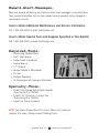
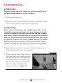
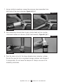
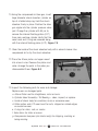
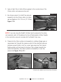
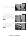
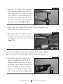
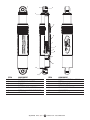
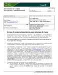
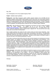
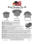
Service_Procedures
Ride Control, LLC.
950 Maplelawn
Troy, MI 48084 USA
800-999-3903
rydefx.com
Information contained in this publication was in effect at the time the publication was approved for
printing and is subject to change without notice or liability. Ride Control, LLC., reserves the right to
revise the information presented or to discontinue the production of parts described at any time.
Ride Control, LLC.
All Rights Reserved
Copyright 2009
Printed in USA
MM-0788
December, 2011
Hazard_Alert_Messages_
Read and observe all Warning and Caution hazard alert messages in this publication.
They provide information that can help prevent serious personal injury, damage to
components, or both.
How to Obtain Additional Maintenance and Service Information
Call 1-800-999-3903 or email [email protected]
How to Obtain Special Tools and Supplies Specified in This Bulletin
Call 1-800-999-3903 or email [email protected]
Required_Tools_
•
•
•
•
•
•
•
•
•
Interlocking Channel Pliers
5/64” Allen Wrench
Slotted Head Screwdriver
Torque Wrench
1/2” Wrench
Vernier Calliper or Micrometer
Pic Tool
Nitrogen Regulator
Air Compressor with blow gun attachment
Specialty_Tools_
•
•
•
RydeFX Gas Charge Tool (Inflation Needle)
Ryde Control P/n: 390300
RydeFX I.F.P Extraction / Locator Tool
Ryde Control P/n: 390304
RydeFX Air Pump (Included)
NOTE: The 40mm Chrome Rod (O.D.) has a 36mm (I.D.) pressure
chamber that uses a 36mm Internal Floating Piston.
RydeFX
Air_2.0
1
Service
Procedures
Disassembly_
n Warning_
To prevent serious eye injury, always wear safe eye protection when
you perform maintenance or service procedures.
1. Wear safe eye protection.
2. Remove the shock from the vehicle. Refer to your snowmobile owners
manual for instructions on proper removal procedures.
n Warning_
Before using a solvent cleaner, you should be aware that it can be
flammable, poisonous and cause burns. Some examples of solvent
cleaners are carbon tetrachloride, and emulsion-type and petroleumbase cleaners. Carefully read and follow the manufacturer's instructions.
Wear safe eye protection and clothing that protects your skin. Do not
use gasoline, or solvents that contain gasoline. Gasoline can explode.
Also take care that you correctly use hot solution tanks or alkaline
solutions. Carefully read and follow the manufacturer's instructions.
3. Wash the shock body parts in a solvent cleaner. Use compressed air
to remove sand and dirt, and dry components.
Figure 2.0
4. Remove bearing, sleeve and/or bushings
from lower shock mount eyelet. Use a vise
with soft-jaws to secure the lower mount
of the shock absorber. If you secure the
shock absorber using any other method,
you can damage or mark the shock
absorber body cylinder. Figure 2.0
RydeFX
Air_2.0
2
Service
Procedures
Figure 3.0
5. Use Allen wrench to remove the small
button head screws from the pressure
valve assemblies at both ends of the
shock absorber. Figure 3.0
n Warning_
The shock absorber contains nitrogen gas that is under extreme
pressure. You must release all of the pressurized gas from the shock
absorber before removing the pressure valve assembly. Use caution
when releasing the gas and allow the pressure to discharge completely.
Servicing a shock absorber that contains pressurized gas can cause
the gas and shock absorber oil to eject the pressure valve assembly
from the shock absorber body cylinder. Serious personal injury and
damage to components can occur.
Figure 4.0
6. Loosen the pressure valve assemblies on
both ends of the shock absorber by using
a slotted screwdriver to turn the pressure
valve assembly screw counterclockwise two
full rotations. Allow gas pressure to fully
escape past each valve assembly O-ring.
Gas chambers are depressurized when
there is no audible sound of escaping gas
Figure 4.0
n Warning_
Nitrogen gas is under extreme pressure. Use caution when releasing
nitrogen gas from shock. Protective eyewear should be worn to avoid
risk of injury.
RydeFX
Air_2.0
3
Service
Procedures
7. Using a slotted screwdriver, remove the pressure valve assemblies from
both ends of the shock absorber. Figure 5.0_5.1
Figure 5.1
Figure 5.0
8. Use interlocking channel pliers to grip cylinder head and turn counter
clockwise to loosen and remove cylinder head assembly. Figure 6.0_6.1
Figure 6.1
Figure 6.0
9. Pour the shock oil out of the large diameter shock absorber cylinder.
Discard the used oil into an approved storage container and dispose of
it appropriately. Do not reuse the damper oil. Always use new oil for
assembly procedures.
RydeFX
Air_2.0
4
Service
Procedures
Figure 7.0
10. Using the compressed air blow gun, invert
large diameter shock absorber cylinder on
top of a folded shop rag. Hold the shock
absorber firmly in place. Position the blow
gun nipple into the cylinder pressure valve
port. Charge the cylinder with 90 psi to
remove the internal floating piston (I.F.P)
from main working cylinder. Verify that the
wear band and O-ring are removed along
with the internal floating piston (I.F.P). Figure 7.0
11. Clean the inside of the shock absorber body with a solvent cleaner. Use
compressed air to dry the shock absorber.
Figure 8.0
12. Place the 40mm piston rod upper mount
into a bench vise. Remove the piston and
valve. Arrange the parts in the order you
disassembled them. Figure 8.0
13. Inspect the following parts for wear and damage.
Replace worn or damaged parts.
a. 40mm Piston rod for straightness, nicks or burrs.
b. Cylinder Head Assembly / DU Bearing – clean, inspect, or replace.
c. Inside of shock body for scratches, burrs or excessive wear.
d. Teflon piston and I.F.P wear band for cuts, chipped or nicked edges,
or excessive wear.
e. O-rings for nicks, cuts, or cracks.
f. Valve discs for kinks or waves.
g. Compression bumpers (ski shocks only) for chipping, cracking or
being missing.
RydeFX
Air_2.0
5
Service
Procedures
Assembly_
1. Place the 40mm piston rod upper mount into the soft-jaw vise.
Reassemble piston rod assembly in the order you disassembled it. Verify
that the rebound and compression disc (shim) stacks are in the same
order that they were before disassembly.
n Caution_
Tighten the locking bolt to 28-32 ft-lb (39-44 Nm.). Do not overtighten
the bolt. Damage to the piston and valves will occur.
n Warning_
Take care when you use LOCTITE® adhesive to avoid serious personal
injury. Read the manufacturer's instructions before using this product.
Follow the instructions carefully to prevent irritation to the eyes and
skin. If LOCTITE® adhesive material gets into your eyes, follow the
manufacturer's emergency procedures. Have your eyes checked by
a physician as soon as possible.
Figure 10.0
2. Apply LOCTITE® 290 threadlocking
compound to the inside thread of the 40mm
rod. Thread the piston assembly by hand.
Use a torque wrench to tighten the locking
bolt to 28-32 ft-lb (39-44 Nm.).
Do not overtighten the locking bolt.
Figure 10.0_10.1_10.2
Figure 10.2
Figure 10.1
RydeFX
Air_2.0
6
Service
Procedures
3. Apply of light film of white lithium grease to the counter bore of the
40mm piston rod pressure valve port.
Figure 11.0
4. Use torque wrench to install the pressure
assembly into the 40mm piston rod valve
port and tighten to 100-110 in-lb (12-13 Nm.).
Figure 11.0
NOTE: If you are using the RydeFX inflation tool to pressurize the piston
rod assembly, refer to Procedures for Use of Replaceable Inflation Needle
in the instruction manual included with the RydeFX tool case.
5. Pressurize the 40mm piston rod assembly by adding nitrogen gas or
compressed air through the pressure valve to the specified pressure
(reference specification chart for correct gas pressure) The internal
floating piston will be forced to the top of the cylinder beneath the
piston rod assembly. The 40mm piston rod assembly is now fully
pressurized.Figure 12.0_12.1
Figure 12.1
Figure 12.0
Schrader valve adaptor may not be exactly as illustrated
RydeFX
Air_2.0
7
Service
Procedures
Figure 13.0
6. Use a vise with soft-jaws to secure the
lower mount of the shock absorber. If you
secure the shock absorber using any other
method, you can damage or mark the
shock absorber body cylinder. Figure 13.0
NOTE: Depending on which shock absorber you are servicing, adjust the
I.F.P location tool to the specified depth.
Figure 14.0
7. Thread the positioning head onto the I.F.P
locator tool and adjust the top of the value
indicator to the specified depth from the top
of the 47mm cylinder (reference specification
chart for correct depth measurement).
Figure 14.0
Figure 15.0
8. Apply a thin film of shock oil onto the
floating wear band and O-ring. Install the
floating piston into the top of the shock
absorber body. Position the piston
approximately 1.0” (25mm) in depth.
Figure 15.0
RydeFX
Air_2.0
8
Service
Procedures
Figure 16.0
9. Using the I.F.P Locator tool as a handle,
push the floating piston down into the
shock absorber, until the value indicator
knob contacts the shock absorber body.
Take care not to damage the I.F.P wear
band and O-ring. The piston should now
be positioned correctly. Figure 16.0
10. Apply of light film of white lithium grease to the counter bore of the
40mm piston rod pressure valve port.
Figure 17.0
11. Use torque wrench to install the pressure
assembly into the 47 cylinder valve port
and tighten to 100-110 in-lb (12-13 Nm.).
Figure 17.0
NOTE: During installation some shock absorber oil will overflow. Wrap a
shop cloth around the shock absorber body to absorb any overflow.
Figure 18.0
12. Fill the shock absorber body with new
shock oil, preferably RydeFX SLIDE oil
(reference specification chart for correct
oil volume). Allow a couple of minutes for
all the air bubbles to rise to the top to
ensure no air is trapped. Trapped air can
affect damper performance. Figure 18.0
RydeFX
Air_2.0
9
Service
Procedures
Figure 19.0
13. Inverted 40mm piston rod assembly.
Pour a small amount of shock oil into
the center of the locking piston bolt, until
oil purges from the bolt. Figure 19.0
Figure 20.0
14. With the cylinder head assembly pushed
down against the piston, carefully insert
the piston rod assembly into the cylinder.
Slightly rotate the piston rod to allow piston
to enter shock body bore. Figure 20.0
NOTE: Slowly push the piston rod and assembly into shock body. If you
push it too quickly, you will displace the internal floating piston (I.F.P) from
its original position, which can affect damper performance.
15. Slowly push the piston rod and assembly into the shock absorber body,
until the cylinder head assembly bottoms on the cylinder counter bore.
Use a slight up-and-down movement, if necessary, to allow all air to
pass through the piston assembly.
Figure 21.0
16. Use interlocking channel pliers to grip the
cylinder head. Turn the head clockwise to
tighten it securely onto the shock absorber
cylinder. Figure 21.0
RydeFX
Air_2.0
10
Service
Procedures
NOTE: If you are using the RydeFX inflation tool to pressurize the 47mm
shock absorber cylinder, refer to Procedures for Use of Replaceable
Inflation Needle in the instruction manual included in the RydeFX tool case.
17. Pressurize the shock absorber 47mm main working cylinder by adding
nitrogen gas or compressed air through the pressure valve to the
specified pressure (reference specification chart for correct gas pressure).
Once the shock absorber is pressurized, the piston rod should fully
extend from the shock absorber body. Figure 22.0_22.1
Figure 22.1
Figure 22.0
Schrader valve adaptor may not be exactly as illustrated
18. Install the small button head screw into the pressure valve assembly
and tighten securely.
19. Reinstall sleeve and bushings in lower shock absorber mount.
RydeFX
Air_2.0
11
Service
Procedures
1
3
4
2
5
6
7
8
9
10
11
12
14
13
ITEM
1
2
3
4
5
6
7
COMPONENT
END CAP
COMPRESSION BUMPER
BUSHING
SLEEVE
CYLINDER HEAD ASSEMBLY
INTERNAL FLOATING PISTON (IFP)
IFP O-RING
RydeFX
Air_2.0
ITEM
8
9
10
11
12
13
14
12
Service
COMPONENT
ROD HEAD ASSEMBLY + SPRING
PISTON
TOP OUT WASHER
PISTON BUSHING
IFP O-RING WEAR BAND
VALVE SCREW
PRESSURE VALUE
Procedures
Air_Pump_and
Schrader_Valve_Kit_
All aftermarket RydeFX AIR 2.0 shock absorbers come with an optional air
pump and Schrader valve kit which can be used as an alternative method
to adjusting the pressure of the shock absorber air spring. Installing the
Schrader valve kit, along with use of the air pump, accommodates the ease
of adjustment to the 47mm cylinder spring pressure while on the trail or as a
substitute to using nitrogen gas with the RydeFX Gas Fill Tool (P/n: 390300).
n Warning_
To prevent undesirable changes in dampening performance, it is
recommended that you follow the manufacturer guidelines when
making air pressure and IFP (Internal Floating Piston) adjustments
to your AIR 2.0 shock absorbers with the Schrader valve kit.
GAS PRESSURE ADJUSTMENTS TO SPRING PRE-LOAD
47mm Aluminum Cylinder Gas Chamber Adjustments
It is recommended that adjustments are only made to the gas chamber in
the 47mm aluminum cylinder as this modifies the initial air spring pressure
(preload) of the shock stroke and should be a sufficient adjustment for the
majority of riders. Use only Air or Nitrogen gas when making adjustments
to air spring pressure.
It is recommended that you do not increase the pressure in the 47mm
aluminum cylinder gas chamber by more than 20-40 PSI at a time or
beyond a maximum pressure of 100 PSI.
n Caution_
A change of 5 PSI in either direction can have a significant impact on
ride quality. Adjustments to air pressure should be made in small
increments to avoid harsh handling.
RydeFX
Air_2.0
13
Service
Procedures
40mm Piston Rod Gas Chamber Adjustments
It is recommended that you do not adjust the pressure in the 40mm
chrome cylinder. It has been set-up from the factory to ensure there is
sufficient stroke while preventing the shock from bottoming out. The gas
chamber in the 40mm chrome cylinder is charged to 160 PSI from the
factory and adjusts the final portion of the shock stroke.
PROCEDURES FOR INSTALLING SCHRADER VALVE KIT
n Warning_
To prevent serious eye injury, always wear safe eye protection
when you perform maintenance or service procedures.
1. Wear safe eye protection
2. Use Allen wrench to remove the small button head screw from
pressure valve assembly from the 47mm cylinder end.
n Warning_
The shock absorber contains nitrogen gas that is under extreme
pressure. You must release all of the pressurized gas from the shock
absorber before removing the pressure valve assembly. Use caution
when releasing the gas and allow the pressure to discharge
completely. Servicing a shock absorber that contains pressurized
gas can cause the gas and shock absorber oil to eject the pressure
valve assembly from the shock absorber body cylinder. Serious
personal injury and damage to components can occur.
3. Loosen pressure value assembly by using a slotted screwdriver to turn
the pressure valve assembly screw counter clockwise two full rotations.
Allow gas pressure to fully escape past the valve assembly O-ring. The
gas chamber is depressurized when there is no audible sound of
escaping gas.
4. Remove the pressure valve assembly from the 47mm cylinder end.
5. Thread the Schrader valve assembly in clockwise and hand tighten
using a 1/2” wrench.
RydeFX
Air_2.0
14
Service
Procedures
Pump_Instructions_
To Use:
1. Thread silver pump head onto shock absorber valve
2. Inflate shock absorber to desired pressure
3. Adjust pressure by pressing bleed valve to release 2.0-3.0 psi at a time
4. Unthread pump head from the shock absorber valve
NOTE: You may hear a release of air when you detach the pump from the
shock absorber valve. This air is being released from the pump hose, not
from the shock absorber.
MM-0788
Issued April 15, 2007
Page 7 Copyright Ride Control LLC. 2009
RydeFX
Air_2.0
15
Service
Procedures