1
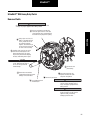
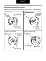
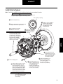
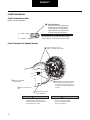
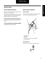
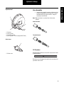
Fuller® Heavy-Duty Clutches
More time on the road®
Service Manual
CLSM0200
January 2008
Solo® Heavy-Duty
Easy-Pedal
TM
Value Clutch
UltraShift DM Heavy-Duty
TM
Warnings
Warnings and Cautions
Use of other than recommended tools, parts, and instructions
listed in this manual may place the safety of the service technician or vehicle driver in jeopardy.
Repair Warnings
The major cause of clutch failure is excessive heat. Excessive
heat generated between the flywheel, driven discs, intermediate plate and pressure plate can cause the metal to flow and
the material to be destroyed. If this occurs, the clutch can
burst which can cause property damage, serious bodily injury
or death. In order to prevent clutch failure resulting from
excessive heat:
1.
Do not exceed recommended vehicle loads.
2.
The clutch should only be used for the recommended applications.
3.
Drivers should be properly trained in starting, shifting and operation of the clutch.
4.
Drivers should report erratic clutch operation as
soon as possible to permit maintenance personnel to
inspect, adjust or lubricate as required.
5.
Mechanics must be familiar with proper clutch
adjustment, linkage adjustment, lubrication and
other maintenance troubleshooting procedures outlined in the Failure Analysis Guide.
When disassembling various assemblies, lay all parts on a
clean bench in the same sequence as removed to simplify and
reduce the possibility of losing parts.
Since the cost of a new part is generally a small fraction of the
cost of downtime and labor, avoid reusing a questionable part
that could lead to additional repairs and expense.
The removal and installation procedure described for each
component may vary for your vehicle.
For Solo only, install shipping bolts before removing clutch.
IMPORTANT
For service information and assistance, call the Roadranger
Help Desk at 1-800-826-HELP (4357) (Mexico: 01-800-826HELP (4357). You may also find more information about
Eaton Fuller Clutches at www.Roadranger.com.
Every effort has been made to ensure the accuracy of the
information contained in this manual. However, Eaton Corporation makes no warranty, expressed or implied, based on the
information provided.
Table of Contents
Warnings. . . . . . . . . . . . . . . . . . . . . . . . . . . . . . . . . . . . . . . i
Out of Vehicle Resetting Procedure . . . . . . . . . . . . . . . . . . . . . 1
Solo® Heavy-Duty 15.5" Clutch
Install . . . . . . . . . . . . . . . . . . . . . . . . . . . . . . . . . . . . . . . . . . . . . . . . . . . . . . . 2
Set-up . . . . . . . . . . . . . . . . . . . . . . . . . . . . . . . . . . . . . . . . . . . . . . . . . . . . . . 6
Lubricate . . . . . . . . . . . . . . . . . . . . . . . . . . . . . . . . . . . . . . . . . . . . . . . . . . . . 8
Troubleshooting . . . . . . . . . . . . . . . . . . . . . . . . . . . . . . . . . . . . . . . . . . . . . . . 9
Easy-Pedal™ and Value Clutch
Install . . . . . . . . . . . . . . . . . . . . . . . . . . . . . . . . . . . . . . . . . . . . . . . . . . . . . . 15
Set-up . . . . . . . . . . . . . . . . . . . . . . . . . . . . . . . . . . . . . . . . . . . . . . . . . . . . . 20
Lubricate . . . . . . . . . . . . . . . . . . . . . . . . . . . . . . . . . . . . . . . . . . . . . . . . . . . 23
UltraShift™ “DM” Heavy Duty Clutch
Remove . . . . . . . . . . . . . . . . . . . . . . . . . . . . . . . . . . . . . . . . . . . . . . . . . . . . 24
Install . . . . . . . . . . . . . . . . . . . . . . . . . . . . . . . . . . . . . . . . . . . . . . . . . . . . . . 25
Hydraulic Linkage. . . . . . . . . . . . . . . . . . . . . . . . . . . . . . . . 28
General Information . . . . . . . . . . . . . . . . . . . . . . . . . . . . . . 31
Table of Contents
Table of Contents
Out of Vehicle Resetting
Out of Vehicle Resetting Procedure
1 Remove the four (4)
shipping bolts if they have
been installed
2 Support the clutch in an
3 Center the ram and
arbor press with the bearing
facing down.
press downward on the
retainer until it comes to
a stop. Lock the ram in
position.
Note: Make sure
there is at least 1
inch of space to
allow the bearing
to move down
and to provide
access to the
shipping bolts.
4 Slide the wear indicator tab to
the "NEW" position and hold it
in place with a magnet
New
5 Install four (4) shipping bolts
(7/16" x 14 x 1-3/4" UNC, hex
head). Progressively tighten (no
air wrenches) the four (4)
shipping bolts (criss-cross
pattern) until the face of the
pressure plate is 1.75" - 1.78"
(44.4 - 45.2 mm) below the
mounting surface.
New
Shipping Bolts
1.75" - 1.78"
(44.4 - 45.2 mm)
6 Reinstall the clutch using
the original installation
instructions.
1
Note: This important step will reset the
pressure plate spacers and allow the
clutch to release after reinstallation
Solo®
Install Solo® Heavy-Duty 15.5" Clutch Installation
Measure Engine Flywheel Housing and Flywheel
Engine flywheel housing and flywheel must meet these specifications or there will be premature clutch wear. Remove old pilot
bearing. All gauge contact surfaces must be clean and dry. Use a dial indicator and check the following:
Flywheel Face Runout
1 Secure dial
indicator base
to flywheel
housing face.
Pilot Bearing Bore Runout
2 Put gauge finger in
3 Rotate flywheel
revolution. Maximum
runout is .008" (.20 mm).
one revolution.
Maximum runout
is .005" (.13 mm)
Flywheel Housing Face Runout
Flywheel Housing I.D. Runout
base to crankshaft.
finger so that it
contacts pilot
bearing bore.
indicator base to
flywheel housing
face.
3 Rotate flywheel one
1 Secure dial indicator
2 Position gauge
Install
contact with flywheel
face near the outer
edge.
1 Secure dial
2 Put gauge finger
against flywheel
housing pilot I.D.
1 Secure dial
indicator base to
flywheel near the
outer edge.
2
3 Rotate flywheel one
revolution. Maximum
runout is .008" (.20 mm).
Put gauge finger
in contact with
face of flywheel
housing.
3 Rotate flywheel
one revolution.
Maximum runout
is .008" (.20 mm).
2
Solo®
Install Clutch to Flywheel
Install Clutch to Flywheel
IMPORTANT
WARNING
Use the Eaton Fuller Clutch
Selector Guide (CLSL1310) to make sure
you have the right clutch
An assembled clutch weighs about
150 lbs. (68 kg). Avoid the risk of injury. Use
proper equipment when lifting a clutch.
1 Measure the flywheel bore.
Use the Eaton Fuller Clutch
Selector Guide to verify that
the damper will fit into the
flywheel bore.
6 Install two 7/16" x 14
7.0" (8-spring)
8.5" (10-spring)
10.0" (6- and 7-spring, Mack 9-spring)
NOTE: Mack 9-spring for Mack engine only
5 Install second disc onto aligning
UNC x 5" studs into upper
mounting holes. Install
assembled clutch.
tool. Follow the orientation
instructions on the disc.
4 Install intermediate plate into slots
on the clutch cover. Flywheel Side
must face the flywheel.
3 Install disc onto aligning tool.
Follow the orientation
instructions on the disc.
4
2 Insert aligning tool
6
2
8
through bearing.
7
1
5
3
9 Remove four
yellow shipping
bolts in a
crisscross
pattern.
7 Install lock washers and mounting
bolts (7/16" x 14 UNC x 2-1/4"
grade 5) finger tight. Replace
studs with lock washers and bolts.
8 Tighten mounting bolts in a crisscross
pattern starting with a lower bolt (1, 2,
3, 4, 5, 6, 7, 8). Torque to 40–50 lbs.
ft. (54–68 N•m).
10 Remove the
aligning tool.
11
11 Use a 1/4" flat nose punch to
lightly tap four intermediate
plate pins toward the flywheel.
3
Pin
Solo®
Install Transmission
Check Transmission For Wear
Replace any worn components.
Cross Shaft and Bushings
Excessive wear at these points can cause
side loading on the sleeve bushing,
bushing failures and yoke bridge contact
with the clutch when the pedal is down.
Transmission Bearing
Retainer Cap
A worn/rough bearing
retainer cap may cause
the clutch brake to wear
prematurely.
Install
Input Shaft Splines
Any wear on the splines
will prevent the driven
discs from sliding freely,
causing poor clutch
release (clutch drag). Slide
discs full length of shaft to
check for twisted shaft
splines.
IMPORTANT
Do not add lube to the input shaft splines
(Never seize or grease). The discs must be free
to slide.
Release Yoke
Worn fingers can cause
bushing wear and yoke
interference when the
pedal is down.
Input Shaft
Wear (roughness) can
reduce sleeve bushing life
and cause it to come out.
Clutch Brake
Replace.
Measure Input Shaft
Length should be 8.657" (219.89 mm) nominal, and not
greater than 8.71" (221.23 mm). Ref. 1990 SAE
handbook 4:36.106. Replace transmission bearing
retainer cap if length is greater than 8.71" (219.89 mm).
CAUTION
Do not excessively force the
transmission into the clutch assembly
or engine housing. This will cause
damage to the splines of the rear disc
hub that is not warrantable. If the discs
do not slide freely in the input shaft,
investigate the cause of the problem
and make any necessary changes. If the
discs do not slide freely, the clutch will
not release and the transmission will
grind going into gear.
Do not let the transmission drop or
hang unsupported in the driven discs.
This can bend the discs and the clutch
will not release causing damage that is
not warrantable.
Do not use the cross-shaft release lever
(or a pipe over it) to pull the
transmission into its final position.
Pulling the bearing too far during
installation can cause an overstroke
causing the release bearing to move
closer to the transmission (less than
.490"). Follow the Out of Vehicle
Resetting Procedure on page 1.
NOTE: Adjust the linkage until pushing
the pedal down moves the bearing
against the clutch brake. Let up on the
pedal and measure the distance
between the bearing and clutch brake
(should be .490" - .560").
4
Solo®
Fasten Transmission to Flywheel Housing
1 Put transmission in gear. Be sure new clutch
3 Position transmission so it is
square to and aligned with engine.
brake has been installed.
2 Make sure that the yoke fingers remain in
the up position until they are over the
release bearing housing.
4 Mesh splines by moving
transmission forward and
rotating the output shaft.
Standard Yoke
and Bearing
Solo XL Roller Yoke
and Bearing
IMPORTANT
Do not add lube to the input shaft splines (Never
seize or grease). The discs must be free to slide.
4.768”
4.893”
5 Install mounting bolts and
torque to OEM specs.
CAUTION
Do not pull on release arm to install
transmission. This will cause the clutch
to over adjust.
WARNING
Do not let the transmission drop or hang
unsupported in the driven discs. This
can cause the discs to become distorted
and the clutch to not release.
Do not force transmission against
clutch with yoke fingers in the UP
position. This will break the cast
webbing of the clutch causing damage
that is not warrantable.
Do not use excessive force. If it does
not enter freely, investigate the cause of
problem and make any necessary
changes.
5
Solo®
Set-up
Adjust Clutch Linkage
1 Hydraulic Linkages:
Skip to Step 2.
Mechanical Linkages Only:
Adjust the clutch linkage until the
yoke fingers contact the release
bearing (zero free-play in cab).
0.00"
Yoke
Finger
Release
Bearing
2 Press the pedal to the
Set-up
floor up to 5 times, this:
• Moves release bearing
slightly closer to the
transmission
• Gains free-play in cab
5X
.500" - 560"
(12.70 - 14.22 mm)
3 With the pedal up, measure the
distance between the release bearing
and the clutch brake. The correct
distance should be .500" - .560"
(12.70 - 14.22 mm):
• If the distance is more the .560"
(14.22 mm), return to Step 1 and
readjust the clutch linkage.
• If the distance is less the .500"
(12.70 mm), see Troubleshooting on
page 9.
6
Solo®
Verify Clutch Brake Squeeze
WARNING
Use a gauge long enough to
keep hands away from moving
parts.
4 Have an assistant insert .010"
(.25 mm) feeler gauge between
the release bearing and the
clutch brake.
Press the pedal down to the floor
to reclamp the gauge:
• If the gauge does not clamp,
readjust the truck linkage and
move yoke fingers closer to
the bearing.
Yoke
Finger
5 Slowly let up on the pedal and
measure the pedal position at the
moment the gauge can be removed:
• If pedal is more than 1" (25.4 mm)
from the floor, readjust the truck
linkage to move the yoke fingers
further from the release bearing.
Return to Step 4.
Less than 1"
(25.4 mm)
Verify Free-Play
6 Verify there is free-play in the cab. If
not, the truck linkage is not providing
enough stroke, consult OEM manual.
IMPORTANT
DO NOT RESET THE CLUTCH. Do not change
free-play by readjusting the clutch linkage.
7
Release
Bearing
Clutch
Brake
Solo®
Lubricate
Lubricate
Lubricate
NOTE: All clutches use a lithium
base grease with a minimum of
325˚F (163˚C) operating range
meeting N.L.G.I. grade 1 or 2
specs.
NOTE: Apply ample grease that
is visibly exiting the opening and
contacts the transmission shaft.
This will lube the clutch brake
and bushing when the pedal is
pressed.
Zerk
For additional lubrication
information, see TCMT-0021. Yoke
Finger
CAUTION
Input
Shaft
Failure to properly
lubricate the
bearing/bushing will
result in bearing and
sleeve failures.
28
Apply grease to the cross
shaft bushings and linkage
pivot points.
7 Apply grease to input
shaft and yoke fingers.
Input Shaft
IMPORTANT
Do not add lube to the input shaft splines (Never seize
or grease). The discs must be free to slide.
8
Solo®
Solo® Heavy-Duty 15.5" Clutch Troubleshooting
Symptom-Driven Diagnostics
If clutch is out of vehicle, go to out
of vehicle resetting procedure on page 1.
Based on your symptom, the chart will
direct you to the correct solution.
Too Much Free Pedal:
Not Enough Free Pedal:
Go to page 10
Go to page 12
Too much
travel
Pedal travels too far before engaging
clutch. Clutch does not disengage.
Too Much Clutch Brake:
Go to page 10
Too much
brake squeeze
9
Too little
travel
Pedal travels too little before engaging
the clutch.
No Clutch Brake:
Go to page 12
Not enough
brake squeeze
Solo®
Too Much Free Pedal or Too Much Clutch Brake
Too much
travel
Too much
brake squeeze
Troubleshooting
Release
Bearing
1 Measure distance
between release bearing
and clutch brake.
Clutch
Brake
2 Use chart to find
solution.
Measurement
If distance is correct
.490" -.560"
Status
Clutch is
set up correctly
(12.45 - 14.22 mm)
If distance is
Less than .490"
(12.45 mm)
Solution
Problem exists with truck linkage. Repair
according to OEM specifications.
Hydraulic Linkage: Go to page 28
Clutch is not
set up correctly
If clutch was factory installed and was never
removed or if clutch was removed from engine
and reinstalled,
Go to page 11
If new/reman clutch was installed and it never
operated properly, check wear tab position.
If tab at NEW position:
• disc installed incorrectly
Go to page 3, Step 4 and 5
• damper is too large for the flywheel opening
Go to page 3, Step 1
If tab not at NEW position, the bearing may
have been pulled during installation causing
an overadjust.
Go to page 1
10
Solo®
In Vehicle Resetting Procedure
1 Have assistant hold
clutch pedal down.
Hold
6 Push pedal down and
squeeze clutch brake 5
times to reposition
bearing.
2 While pedal is held down,
move wear tab to the left
(New) position.
5X
New
NOTE: All adjustments
must be done through
access panel opening.
If tab will not move, go to
New
5 Remove
page 13.
shipping
bolts.
NOTE: This will remove the gap
between the sleeve and the pin.
3 Let up on pedal. DO NOT
push pedal down again or
wear tab will return to the
wrong position.
Before
After
4 Install and tighten 4
shipping bolts (7/16"
x 14 x 1-3/4 UNC)
until they quit
turning.
Shipping
bolt
Gap
Sleeve
11
No gap
between
sleeve and
pin
Pin
Solo®
Not Enough Free Pedal or No Clutch Brake
Too little
travel
Not enough
brake squeeze
Troubleshooting
Release
Bearing
1 Measure distance
between release bearing
and clutch brake.
Clutch
Brake
2 Use chart to find
solution.
Measurement
If distance is correct
.490" -.560"
Status
Clutch is
set up correctly
(12.45 - 14.22 mm)
If distance is
More than .560"
(14.22 mm)
Solution
Problem exists with truck linkage.
Repair according to OEM specifications.
Hydraulic Linkage: Go to page 28
Clutch is not
set up correctly
If clutch was factory installed
and was never removed,
Mechanical Linkage: Go to page 13
Hydraulic Linkage:
Go to page 28
If clutch was removed from
engine and reinstalled,
Go to page 6
(Setup)
If new/reman clutch was installed
and it never operated properly,
Go to page 6
(Setup)
12
Solo®
In Vehicle Resetting Procedure Using the Solo Resetting Tool
Tool Part Code:
CLMT0001
1
Determine if the release bearing travel is
correct. Measure the distance between the
clutch brake and the release bearing with
the clutch pedal up. If the measurement is
between 0.490 and 0.590, the Solo has set
itself correctly.
Release
Bearing
NOTE: Yoke gap only applies to mechanical
linkage. Most hydraulic linkages operate
without yoke gap.
2
If the release bearing travel is less than 0.490”
the Solo must be reset. A common cuase of this
is the transmission was pulled in with the release
arm during clutch installation.
3
Rotate the engine so that the cam tab can
be reached through the transmission
inspection opening.
4
Push the clutch pedal to the floor. While the
clutch pedal is pushed to the floor have
someone push the cam tab to the new position
using finger pressure or the Solo tool.
Once the cam tab is pushed to the new position
you can release the clutch pedal.
NOTE: If the cam tab does not move, there is
not enough release bearing travel to allow the
cams to seperate. In this case, loosen the
transmission and install 1/2” spacers between
the flywheel housing and bell housing.
With the spacers in place push the clutch pedal
to the floor while someone pushes the cam tab
to the new position. Once the tab is in the new
position release the clutch pedal and remove the
spacers. Torque the transmission mounting
bolts.
13
Clutch
Brake
Measure the release
bearing travel
REPLACE
Solo®
5
6
Install (4) shipping bolts and progressively
tighten by hand until they bottom out. Rotate
the engine to access all 4 bolts.
• 15 1/2” Solo use 7/16 x 14 UNC x 1 3/4”
• Stamped 14” Solo use 3/8 x 16 UNC x 1
1/4”
Shipping Bolt
Remove the (4) shipping bolts. The release
bearing and sleeve will move forward towards
the engine when the bolts are removed. The
Solo is now in the new position.
Tamper Proof
Bolt
Troubleshooting
7
New
With the free pedal removed push the clutch
pedal down at least 5 times. Make sure the clutch
release bearing contacts the clutch brake.
While you enage and release the clutch the cab
free pedal will increase. This indicates the Solo is
adjusting to the environment.
8
Measure the distance between the clutch brake
and the release bearing. It should be between
0.490 and 0.590”.
10
Shipping Bolts
9
Adjust the clutch linkage to achieve 1/8”
clearance between the release yoke and the
release bearing. Verify proper clutch brake
squeeze.
If the release bearing travel is still greater than
0.590” between the clutch brake and the release
bearing, repeat steps 7 and 8.
Verify Clutch Brake Squeeze
WARNING: Use a gauge long
enough to keep hands away
from moving parts.
1 Have an assistant insert .010"
(.25 mm) feeler gauge between
the release bearing and the
clutch brake.
Press the pedal down to the floor
to clamp the gauge:
• If the gauge does not clamp,
readjust the truck linkage and
move the yoke finger closer to
the bearing.
Yoke
Finger
2 Slowly let up on the pedal and measure
the pedal position at the moment the
gauge can be removed:
• If pedal is more than 1" (25.4 mm) from
the floor, readjust the truck linkage to
move the yoke fingers further from the
release bearing. Repeat Step 4.
Release
Bearing
Clutch
Brake
Less than 1"
( 25.4 mm)
14
Easy-Pedal™ and
Value Clutch
Easy-Pedal™ and Value Clutch
Measure Engine Flywheel Housing and Flywheel
Engine flywheel housing and flywheel must meet these specifications or there will be premature clutch wear. Remove old pilot
bearing. All gauge contact surfaces must be clean and dry. Use a dial indicator and check the following:
Flywheel Face Runout
1 Secure dial
indicator base
to flywheel
housing face.
Pilot Bearing Bore Runout
2 Put gauge finger in
contact with flywheel
face near the outer
edge.
1 Secure dial
3 Rotate flywheel
revolution. Maximum
runout is .008" (.20 mm).
one revolution.
Maximum runout
is .005" (.13 mm)
Flywheel Housing Face Runout
Flywheel Housing I.D. Runout
base to crankshaft.
2 Put gauge finger
against flywheel
housing pilot I.D.
1 Secure dial
indicator base to
flywheel near the
outer edge.
2
3 Rotate flywheel one
revolution. Maximum
runout is .008" (.20 mm).
15
finger so that it
contacts pilot
bearing bore.
indicator base to
flywheel housing
face.
3 Rotate flywheel one
1 Secure dial indicator
2 Position gauge
Put gauge finger
in contact with
face of flywheel
housing.
3 Rotate flywheel
one revolution.
Maximum runout
is .008" (.20 mm).
Easy-Pedal™ and
Value Clutch
Install Clutch to Flywheel
WARNING
An assembled clutch weighs about 150 lbs.
(68 kg). Avoid the risk of injury. Use proper
equipment when lifting a clutch.
IMPORTANT
Use the Eaton Fuller Clutch Selector Guide
(CLSL1310) to make sure you have the
right clutch.
For 15.5" Clutch Only (Easy Pedal shown)
1 Measure the flywheel bore.
Use the Eaton Fuller Clutch
Selector Guide to verify that
the damper will fit into the
flywheel bore.
6 Install two 7/16" x 14
5 Install second disc onto UNC x 5" studs into
7.0" (8-spring)
8.5" (10-spring)
10.0" (6-spring, 7-spring and Mack 9-spring)
NOTE: Mack 9-spring for Mack engine only
aligning tool. Follow the
orientation instructions
on the disc.
upper mounting holes.
Install assembled
clutch.
4 Install intermediate plate into slots
on the clutch cover. Flywheel Side
must face the flywheel.
3 Install disc onto aligning tool.
Follow the orientation
instructions on the disc.
2 Insert aligning tool
Install
6
4
8
2
through bearing.
TO
PR
ES S
N
BOLT
R
TU
1
DE
7
pattern starting with a lower bolt (1, 2,
3, 4, 5, 6, 7, 8). Torque to 40–50 lbs. ft.
(54–68 N•m).
9 Verify bearing position is
3/8"–5/8" (9.5–15.9 mm)
from cover.
10 Remove the aligning tool.
Be sure shipping blocks are
removed.
TO
BOLT
RN
punch to lightly tap four pins
toward flywheel (New EP
Only). Reman and Value
clutches do not have pins.
TU
11 Use a 1/4" (6 mm) flat nose
ES S
mounting bolts (7/16" x
14 UNC x 2-1/4" grade 5)
finger tight. Replace
studs with lock washers
and bolts.
8 Tighten mounting bolts in a crisscross
PR
7 Install lock washers and
3
DE
5
Pin
16
Easy-Pedal™ and
Value Clutch
For 14" Clutch Only
Super-duty clutch only:
1 Ensure the correct flywheel depth
is 2-15/16".
3 Install three
equally spaced
anti-rattle springs
2 Put front disc into
flywheel. Flywheel
side must be toward
engine. Use new slots
to put intermediate
plate on pins.
4 Turn intermediate plate
left. Use .006" feeler gauge
to check left pin clearance
on all 6 drive pins.
NOTE: Remove two set
screws. Straighten pins to
increase clearance and
reinstall set screws. Do
not file slots.
8 Install second
7 Install
disc onto
flywheel.
Follow the
orientation
instructions
on the disc.
intermediate
plate onto
drive pins.
6 Install disc
5 Install two 3/8" x 2-1/2"
into flywheel.
Follow the
orientation
instructions
on the disc.
studs into upper mounting
holes.
9 Insert aligning tool
10 Slide cover over
through discs.
aligning tool.
6
4
8
2
12 Tighten mounting bolts in a
TO
ESS
RN
BOLT
TU
PR
7
DE
1
5
3
11 Install lock washers and mounting
bolts (3/8" x 1-1/4" grade 5) finger
tight. Replace studs with lock
washers and bolts.
crisscross pattern starting with
a lower bolt (1, 2, 3, 4, 5, 6, 7, 8).
Torque to 25–35 lbs. ft.
(34–47 N•m).
13 Remove the aligning tool. Be sure
shipping blocks are removed.
17
Easy-Pedal™ and
Value Clutch
Install Transmission
Check Transmission For Wear
Replace any worn components.
Transmission Bearing Retainer Cap
A worn/rough bearing retainer cap may
cause the clutch brake to wear
prematurely.
Cross Shaft And Bushings
Excessive wear at these points can cause
side loading on the sleeve bushing,
bushing failures and yoke bridge contact
with the clutch when the pedal is down.
Input Shaft Splines
Any wear on the splines
will prevent the driven
discs from sliding freely,
causing poor clutch
release (clutch drag). Slide
discs full length of shaft to
check for twisted shaft
splines.
IMPORTANT
Release Yoke
Worn fingers can
cause bushing
wear and yoke
interference when
the pedal is down.
Install
Input Shaft Wear (roughness)
can reduce sleeve bushing life
and cause it to come out.
Do not add lube to the input shaft splines (Never
seize or grease). The discs must be free to slide.
Clutch Brake
Replace.
Measure Input Shaft
Length should be 8.657" (219.89 mm)
nominal, and not greater than 8.71" (221.23 mm).
Ref. 1990 SAE handbook 4:36.106. Replace
transmission bearing retainer cap if length is
greater than 8.71" (219.89 mm).
CAUTION
Do not let the transmission drop or
hang unsupported in the driven discs.
This can bend the discs and the clutch
will not release causing damage that is
not warrantable.
Do not excessively force the
transmission into the clutch assembly
or engine housing. This will cause
damage to the splines of the rear disc
hub that is not warrantable. If the discs
do not slide freely in the input shaft,
investigate the cause of the problem
and make any necessary changes. If the
discs do not slide freely, the clutch will
not release and the transmission will
grind going into gear.
18
Easy-Pedal™ and
Value Clutch
Fasten Transmission to Flywheel Housing
Transmission installation and clutch set-up procedures are the same for the 14" and 15.5" clutch.
3 Position transmission
1 Put transmission in
so it is square to and
aligned with engine.
gear. Be sure new
clutch brake has been
installed.
2 Make sure that the yoke
fingers remain in the up
position until they are over
the release bearing housing.
4 Mesh splines by moving transmission
5 Install mounting bolts and
torque to OEM specs.
NOTE: If you have a hydraulic linkage, go to
WARNING
Do not let the transmission drop or hang
unsupported in the driven discs. This
can cause the discs to become distorted
and the clutch to not release.
IMPORTANT
Do not add lube to the input shaft splines (Never
seize or grease). The discs must be free to slide.
forward and rotating the output shaft.
Do not use excessive force. Do not let
the transmission hang unsupported in
the discs.
page 28.
CAUTION
Do not pull on release arm to install
transmission. This will cause the clutch
to over adjust.
Do not force transmission against
clutch with yoke fingers in the UP
position. This will break the cast
webbing of the clutch causing damage
that is not warrantable.
Do not use excessive force. If it does
not enter freely, investigate the cause of
problem and make any necessary
changes.
19
Easy-Pedal™ and
Value Clutch
Set-up
Set-up
Adjust Bearing Position
1 Measure the distance between the
release bearing and the clutch brake:
• If the distance is correct,
.500" -.560" (12.70 - 14.22 mm),
then Verify Clutch Brake Squeeze,
Step 4.
• If the distance is not between 500" .560" (12.70 - 14.22 mm), then
Change Bearing Position, Step 2.
2 Have an assistant
hold down clutch
pedal.
.500" - 560"
(12.70 - 14.22 mm)
Release
Bearing
Hold
Clutch
Brake
3 Adjust bearing position:
Easy Pedal Only:
Value Clutch Only:
While pedal is held down, push adjusting
nut and turn:
• If measurement was more than .560"
(14.22 mm), turn adjusting nut clockwise.
• If measurement was less than .500"
(12.77 mm), turn adjusting nut
counterclockwise.
While pedal is held down, remove lockstrap and
move adjusting lug:
• If measurement was more than .560" (14.22 mm),
move adjusting lug to the left (shown).
• If measurement was less than .500" (12.77 mm),
move adjusting lug to the right.
Adjusting Nut
TO
PR
ES
N
T
S BOL
TU R
DE
Adjusting
Lug
( Part number 125489 )
Lockstrap
20
Easy-Pedal™ and
Value Clutch
Verify Clutch Brake Squeeze
WARNING
Use a gauge long enough to
keep hands away from moving
parts.
4 Have an assistant insert .010"
(.25 mm) feeler gauge between
the release bearing and the
clutch brake.
Press the pedal down to the floor
to clamp the gauge:
• If the gauge does not clamp,
readjust the truck linkage and
move the yoke finger closer to
the bearing.
Yoke
Finger
5 Slowly let up on the pedal and measure
the pedal position at the moment the
gauge can be removed:
• If pedal is more than 1" (25.4 mm) from
the floor, readjust the truck linkage to
move the yoke fingers further from the
release bearing. Repeat Step 4.
Less than 1"
( 25.4 mm)
21
Release
Bearing
Clutch
Brake
Easy-Pedal™ and
Value Clutch
Set-up
Free-Play
VerifyVerify
Free-Play
Hydraulic
Systems
notany
have
any free-play.
NOTE: NOTE:
Hydraulic
Systems
will notwill
have
free-play.
6 Check distance between
yoke tipsbetween
and bearing
6 Check distance
wear
pads.
This distance
yoke tips and bearing
should
bedistance
1/8" (3.2 mm).
wear pads.
This
not 1/8"
should Ifbedistance
1/8" (3.2is mm).
(3.2
mm),
go
If distance is not 1/8"to Step 7.
(3.2 mm), go to Step 7.
IMPORTANT
IMPORTANT
not change
Do not Do
change
bearingbearing
position.
position.
1/8" 1/8"
(3.2 mm)
(3.2 mm)
Yoke Yoke
Finger
Finger
Release
Release
Bearing
Bearing
NOTE: NOTE:
1/8" (3.2
mm)
1/8"
(3.2 mm)
distance
will create
free- freedistance
will create
play in play
cab. in
Free-play
in
cab. Free-play
in
cab may
bemay
different
on
cab
be different
on
different
truck makes,
different
truck makes,
modelsmodels
and years.
and years.
27
The
shouldshould
allow allow
for a minimum
of of
The linkage
truck linkage
for a minimum
27 truck
.685" of
yoke
finger
movement;
.125"
for
free-play,
.685" of yoke finger movement; .125" for free-play,
.500" for
thefor
bearing
and .060"
for clutch
brakebrake
.500"
the bearing
and .060"
for clutch
squeeze.
If
it
is
necessary
to
increase
the
squeeze. If it is necessary to increasefree-play,
the free-play,
adjust upper pedal stop to raise or lower the pedal in
adjust upper pedal stop to raise or lower the pedal in
the cab. If this is not possible, check the OEM parts
the cab. If this is not possible, check the OEM parts
manual to verify the correct clutch arm was installed
manual
at the factory. to verify the correct clutch arm was installed
at the factory.
IMPORTANT
IMPORTANT
not change
free-play
by changing
the bearing
Do notDo
change
free-play
by changing
the bearing
position.
Correct
bearing
position
is .500"-.560"
position.
Correct
bearing
position
is .500"-.560"
(12.70(12.70
- 14.22
mm) mm)
- 14.22
22
Easy-Pedal™ and
Value Clutch
Lubricate
NOTE: All clutches use a lithium
base grease with a minimum of
325°F (163°C) operating range
meeting N.L.G.I. grade 1 or 2
specs.
NOTE: Apply ample grease that
is visibly exiting the opening and
contacts the transmission shaft.
This will lube the clutch brake
when the pedal is pressed.
For additional lubrication
information, see TCMT0021.
Zerk
Yoke
Finger
CAUTION
Input
Shaft
Failure to properly
lubricate the
bearing/bushing will
result in bearing and
sleeve failures.
29
Apply grease to the cross
shaft bushings and linkage
pivot points.
8 Apply grease to input
shaft and yoke fingers.
Input Shaft
IMPORTANT
Do not add lube to the input shaft splines (Never seize
or grease). The discs must be free to slide.
23
UltraShift™
UltraShift™ DM Heavy Duty Clutch
Remove Clutch
WARNING
An assembled clutch weighs about 182 lbs. (82 kg). Avoid the risk
of injury. Use proper equipment when lifting a clutch.
1 Prior to removing the transmission,
rotate the engine until one of the jack
screw locations can be viewed through
the clutch housing inspection opening.
Remove
2 Using a piece of 5/16" x 18
UNC x 3" threaded rod (jack
screw), install two nuts on
one end and lock them
together. This will allow you
to turn the jack screw in and
out of the cover assembly.
3 Install the jack screw into one of the
four holes located adjacent to the
clutch mounting bolts. This forces
the pressure plate forward clamping
the discs and holding them in place.
CAUTION
Do not overtighten the jack
screw. Tightening more than 9
lbs. ft. can cause permanent
clutch damage.
8 Remove the old
pilot bearing.
4 Remove the transmission,
7 Unbolt the clutch from the
supporting its weight to prevent
damage to the clutch discs.
6 Remove the jack screw.
5 Insert alignment shaft
and clutch jack.
flywheel and slide the clutch
away from the flywheel.
WARNING
An assembled clutch weighs about
182 lbs. (82 kg). Avoid the risk of
injury. Use proper equipment when
lifting a clutch.
CAUTION
When removing the clutch, the
flywheel side disc can fall off of the
alignment shaft, permanently
damaging the driven disc.
24
UltraShift™
Measure Engine Flywheel Housing and Flywheel
Engine flywheel housing and flywheel must meet these specifications or there will be premature clutch wear. All gauge contact
surfaces must be clean and dry. Use a dial indicator and check the following:
Flywheel Face Runout
1 Secure dial
indicator base
to flywheel
housing face.
Pilot Bearing Bore Runout
2 Put gauge finger in
contact with flywheel
face near the outer
edge.
1 Secure dial
3 Rotate flywheel
revolution. Maximum
runout is .008" (.20 mm).
one revolution.
Maximum runout
is .005" (.13 mm)
Flywheel Housing Face Runout
Flywheel Housing I.D. Runout
base to crankshaft.
2 Put gauge finger
against flywheel
housing pilot I.D.
1 Secure dial
indicator base to
flywheel near the
outer edge.
2
3 Rotate flywheel one
revolution. Maximum
runout is .008" (.20 mm).
25
finger so that it
contacts pilot
bearing bore.
indicator base to
flywheel housing
face.
3 Rotate flywheel one
1 Secure dial indicator
2 Position gauge
Put gauge finger
in contact with
face of flywheel
housing.
3 Rotate flywheel
one revolution.
Maximum runout
is .008" (.20 mm).
UltraShift™
Install Clutch to Flywheel
Note: If installing a new DM, follow the installation directions that are provided in the box.
WARNING
An assembled clutch weighs about 182 lbs. (82 kg). Avoid the risk
of injury. Use proper equipment when lifting a clutch.
10.0" (6-spring, 7-spring)
1 Install new pilot bearing.
5 Install two 7/16" x 14 UNC x 5"
2
studs into upper mounting
holes. Using clutch jack or
other lifting device, install
assembled clutch.
Measure the flywheel bore to verify that the
damper will fit into the flywheel bore.
3 Insert aligning tool through
DM Clutch and rear disc.
4 Install second disc onto
aligning tool. Follow the
orientation instructions
on the disc.
WARNING
The intermediate plate is bolted
to the cover assembly and the
rear driven disc is held in place
between the pressure plate and
intermediate plate. DO NOT
UNBOLT the intermediate plate
from the cover assembly.
6
2
4
Install
7
8
3
6 Install lock washers and
mounting bolts (7/16" x 14
UNC x 2-1/4" grade 5) finger
tight. Replace studs with
lock washers and bolts.
1
5
7 Tighten mounting bolts in a
10 Remove the aligning tool.
8 Using a piece of 5/16" x 18
9 Install the jack screw into one of the
four holes located adjacent to the
clutch mounting bolts. This forces
the pressure plate forward clamping
the discs and holding them in place.
Be sure the hole chosen as at the 6
o'clock position to allow for removal
after the transmission is installed.
UNC x 3" threaded rod (jack
screw), install two nuts on
one end and lock them
together. This will allow you
to turn the jack screw in and
out of the cover assembly.
crisscross pattern starting
with a lower left bolt (1, 2, 3,
4, 5, 6, 7, 8). Torque to
40–50 lbs. ft. (54–68 N•m).
CAUTION
Do not overtighten the jack
screw. Tightening more than 9
lbs. ft. can cause permanent
clutch damage.
26
UltraShift™
Install Transmission
Check Transmission for Wear
Replace any worn components.
1
Input Shaft Splines
Any wear on the splines will prevent
the driven discs from sliding freely,
causing poor clutch release (clutch
drag). Slide discs full length of shaft
to check for twisted shaft splines.
IMPORTANT
Do not add lube to the input shaft splines (Never
seize or grease). The discs must be free to slide.
Fasten Transmission to Flywheel Housing
1 Position transmission so it is
square to and aligned with engine.
5 Reconnect UltraShift
2 Mesh splines by moving transmission
wiring harness.
forward and rotating the input shaft.
Do not use excessive force. Do not let
the transmission hang unsupported in
the discs.
4 Remove the jack screw.
3 Install mounting bolts and
torque to OEM specs.
WARNING
Do not let the transmission drop or hang
unsupported in the driven discs. This
can cause the discs to become distorted
and the clutch to not release.
27
CAUTION
Do not use excessive force. If it
does not enter freely, investigate
the cause of problem and make
any necessary changes.
Hydraulic Linkage
Hydraulic Linkage
Hydraulic Linkage
Verify Linkage System Stroke
Master Cylinder Installation
Measure the release bearing position with the pedal up and
pedal down to verify bearing travel.
Master Cylinder
The hydraulic linkage should allow for a minimum of .600" of
yoke finger movement: .500"-.560" for clutch release plus
additional movement for clutch brake squeeze.
If the system does not provide enough movement of the
release bearing, the clutch will not adjust and the bearing will
move away from the transmission and lose clutch brake
squeeze.
Master cylinder may be mounted at any angle ranging from
vertical to horizontal, depending on application.
2
1
If the system is operational, clutch replacement may be necessary. If replacing the clutch, you must adhere to OEM warranty guidelines prior to claim disposition.
3
5
4
1 - Master cylinder
2 - Reservoir
3 - Pushrod
4 - Bolts (2), M8 x 1.25 mm (torque 20-25 N•m)
5 - To booster or slave
Remote Reservoir
Constant rise in hose from master cylinder to reservoir.
28
Hydraulic Linkage
Adjustment
Transmission Installation
Freeplay
Non-Synchronized
Depending on the application, freeplay can be achieved by
adjusting upper pedal stop or by adjusting master cylinder
pushrod.
1
1
5
1 - Freeplay 3-8 mm
2
4
Clutch Brake Squeeze
3
For non-synchronized applications only.
1 - Clutch servo
2 - To master cylinder
3 - Connect air supply 30 psi source; Bolts (4),
M16 x 1.5 mm (torque 20-25 N•m)
4 - Bolts (2), M8 x 1.25 mm (torque 20-25 N•m)
5 - Pushrod
Slave Cylinder
1
1 - Clutch brake squeeze 13-50 mm
1
1 - Slave cylinder
29
Hydraulic Linkage
1.
1
Connect hose assembly to master cylinder and slave
or booster. Depending on hose type, this is either a
threaded connect or snap-to-connect. Torque all
connectors to 20-25 N•m.
Note: Make sure there is a constant rise to the master
cylinder.
Snap-to-Connect
2
4
3
1 - Pushrod
2 - Slave cylinder
3 - To master cylinder
4 - Bolts (4), M8 x 1.25 mm (torque 20-25 N•m)
Threaded Connect
Clutch Servo
1
Fill Procedure
1 - Clutch servo
Recommended methods are vacuum fill or pressure fill. Refer
to OEM procedure.
CAUTION
Do not press or disengage clutch pedal when removing slave
cylinder or clutch servo.
30
Hydraulic Linkage
Hose Assembly
Synchronized
General Information
General Clutch Information
Function of a Clutch
Any modern day clutch, whether designed for an automobile
or heavy truck, performs several important tasks allowing for
safe and convenient operation of the vehicle.
In a vehicle powertrain, the clutch is the device that interrupts
the flow of power from the engine flywheel to the transmission. To start a gasoline or diesel engine, the flywheel must be
able to turn freely without propelling the vehicle. By disengaging the clutch, the drivetrain is effectively disconnected from
the rotation of the flywheel allowing the engine to start.
Manual transmissions, whether synchronized (synchromesh)
or non-synchronized (constant mesh), require an interruption
of engine torque to complete a gear change. To make a gear
change, the clutch pedal is depressed, breaking torque. This
is followed by altering engine speed to more closely match the
transmission input shaft (clutch disc) speed. After the proper
gear is selected, the clutch pedal is then slowly released. As
the clutch disc(s) are compressed, the relative slip speed
between the flywheel and the transmission input shaft reaches
zero and the clutch is completely engaged and capable of carrying full engine torque. With non-synchronized gearboxes,
double clutching (a momentary partial engagement of the
clutch made while the transmission is in neutral) is often necessary to allow rotational speeds of gears to become the same
and complete the gear change.
With the advent of transmission automation, breaking torque
and altering flywheel speed is accomplished via electronic
throttle control and engine braking. The clutch pedal is used
only when starting the engine, launching the vehicle from a
stop, and when the vehicle slows to a stop.
The last function of the clutch is mitigating torsional vibrations. With any in-line, six-cylinder engine there are three (3)
distinct power pulses occurring during each revolution of the
flywheel. With each firing of a cylinder, the flywheel speeds up
then slows down, very quickly, resulting in a torsional vibration. This vibration can damage drivetrain components in
short order if left uncontrolled. The coil springs in a driven
disc damper absorb much of the vibration. The resonant (generally the least expensive drivetrain component) is considered
the “fuse” of the system. Failure of a clutch damper section is
usually an indication of a serious torsional vibration systems
problem or shock loading due to driver abuse.
Clutches are assemblies made up of many different components utilizing many different types of materials. This section
31
describes the major components which make up a complete
Eaton Fuller Clutch installation.
The following are the major components used to make up a
clutch installation:
•
•
•
•
Cover Assembly (contains pressure plate)
Intermediate Plate – (only in 2-plate clutches)
Driven Disc(s)
Clutch Brake
Neutral Idle Rattle
Neutral idle rattle is a system issue. It occurs when the engine
is idling with the transmission in neutral and the clutch pedal
in the up position. As the engine idles, the firing pulses cause
the flywheel to oscillate as it is rotating. This oscillation is
transmitted through the input shaft and into the transmission
gearing. This oscillation causes the transmission gears to
impact one another resulting in a sometimes objectionable
noise. While this noise is an annoyance, it is in no way damaging to the transmission and other components.
In the past, free travel dampers have been used to overcome
this phenomenon. As systems have changed, in terms of
mass, inertia, and fuel injection pressures, free travel has
become a less effective means of control.
Free travel, simply stated, is the free left or right rotation of
the driven disc hub before engaging the clutch damper. This
first stage isolates some of the flywheel oscillation energy and
prevents or reduces the idle rattle.
Pre-damper technology is now available in some mediumand heavy-duty clutch applications and performs the same
function as the free travel. By adding a dampened first stage,
it is more effective at limiting neutral idle rattle. Generally, the
pre-damper springs are very small and softer in rate than the
main damper springs.
In diagnosing neutral idle rattle complaints, first try to fully
depress the clutch pedal. This will disconnect the engine from
the transmission. Secondly, try raising the engine idle speed
with the clutch pedal up. This may smooth out the engine firing and may reduce, or eliminate, the noise.
If you have neutral idle rattle, determine what clutch is
installed in the vehicle. It may already have a pre-damper
clutch in it. If it is already equipped with a pre-damper clutch,
then there is no benefit to changing the clutch.
General Information
Clutch Disc Dampening Characteristics
The Eaton Fuller Solo is the industry’s first adjustment-free
clutch. With every push of the pedal, Solo’s innovative wearadjusting technology senses for wear and makes any adjustments necessary.
A key function of a clutch is to mitigate naturally occurring
vibrations of the engine flywheel from reaching the transmission and the other components further down the drivetrain.
This is accomplished by employing torsional spring dampers
to the clutch pack. These springs take the form of coil springs,
configured inside the clutch disc, that compress with the
application of torque. The torque path through the damper
begins at the friction interface at the facings, proceeds to the
steel carrier disc and moves into the disc reinforcing plates
where the springs are located. The springs are compressed,
transmitting force to the spring covers which are rigidly
attached to the hub. Torsional rate is defined as the amount of
torque required per degree of center hub rotation. There are
three basic categories of torsional rates for clutch dampers:
rigid, standard, soft.
Why There is No Need to Adjust Eaton Fuller
Solo™ Clutches
If the Solo Clutch is properly installed and the linkage is setup properly, the Solo Clutch should never need internal or
external adjusting.
The Solo Clutch automatically keeps the proper release bearing position and clutch free pedal position with two opposing
cams. As the Solo Clutch wears, the cams separate from each
other keeping the proper release bearing position. This in turn
maintains the proper clutch free pedal position.
How it Works
Eaton Fuller Solo’s wear-adjusting technology comes from
two sliding cams. With every push of the pedal, the clutch
senses for wear and makes any adjustments necessary. The
cams rotate to maintain the proper adjustment throughout the
life of the clutch. On top of the upper cam, a clutch wear indicating tab mirrors the cams’ movement to let you know when
it’s time to replace the clutch. The result of Solo’s constant
adjustment is greater longevity and a reduction in maintenance and labor costs.
Rigid and Clutch Discs - Rigid discs and clutch discs with no
spring package whatsoever, act as a nearly direct link from
the engine flywheel to the transmission and offer no protection against torsional vibration. Their use should be limited to
older mechanically-fueled engines where clutch replacement
cost is paramount over long component life. Rigid clutch
discs are never used in new OEM applications.
Standard Dampers - Standard dampers include all 10-spring
and most 8- spring types. The springs used in these dampers
are approximately 1.5" long and do not offer a large amount of
deflection before coil lock takes place. While these dampers
were completely adequate for most heavy duty applications
several years ago, they are generally incapable of reducing the
engine flywheel vibrations developed with slow speed electronically fueled engines. The use of standard dampers in
heavy duty applications has virtually ceased in OEM applications. The trend is to use more capable soft-rate dampers.
Soft-Rate Dampers - Soft-rate dampers, like the heavy duty 6
and 7-spring types, offer much better protection against
engine flywheel induced torsional vibration. Their springs are
characteristically longer than springs used in standard rate
dampers and offer more deflection before coil lock occurs.
This larger spring deflection is equated to lower torsional
spring rate. With lower torsional rate, the resonant frequency
of the complete drivetrain is lowered; usually to a point of a
few hundred RPM below normal engine operating range. With
the addition of hysteresis or Coulomb dampening (the energy
expelled as the damper is exercised), the magnitude of the
vibrations is reduced further, adding to the dampers benefit.
32
General Information
Solo™ Clutches
General Information
Clutch Disc Friction Material
Clutch Torque Capacity
Organic facings, often called “rag” facings, get their name
from the high concentration of organic rubber and binder
agents that make up their composition. Fiberglass cord (or
similar material) is woven into the material matrix and adds
burst strength and improves friction and wear properties.
Asbestos has not been used in organic friction material since
the early 1980's. Organic facings are used without exception
in passenger car and light truck applications. This is so
because of smooth engagement properties and the relative
light torque loads imposed on the clutch. In general, organic
friction material lacks in performance in wear rate, coefficient
of friction (ability to carry torque), and resistance to fade
(abuse tolerance) when compared to cera-metallic friction
material. The use of organic friction material in heavy vehicles
has significantly declined over the past decade. Wear life and
its maximum limit to 1,400 ft. lbs. (1892 N•m) of torque in
15.5" clutches are the primary reasons.
It is imperative to understand the factors that influence friction force because this device transmits torque via friction.
The fundamental equations that describes friction is:
Cera-metallic (Ceramic) friction facings are composite material (copper, sand and other friction modifiers and binder
agents). The dry raw materials are mixed in bulk, poured into
die cavities, compressed, sintered in an controlled atmosphere, then brazed into a steel backer plate to facilitate rivet
attachment to the driven disc. Compared to organic friction
material, cera-metallics have improved performance in the
areas of wear rate, resistance to fade (abuse tolerance), and
coefficient of friction (ability to carry torque). It is for this reason that cera-metallics make up the vast majority of OEM
builds.
Clutch Slippage
Slippage will cause significant heat build-up and rapid wear of
the clutch pack. If the clutch pack temperature raises beyond
the facing threshold temperature, the facing may disintegrate.
Slippage is the result of loss of clamp load due to lack of
adjustment, loading the clutch beyond its design torque rating, or the clutch has reached the end of its design life. With
the ability to re-rate an electronic controlled diesel engine, it is
quite easy to delivery torque to the clutch beyond its design
capacity. Before an engine re-rating is performed, confirm
that the clutch and other drivetrain components are capable of
carrying the increased torque and power.
33
F(f) = uN
Where F(f) = Force due to friction
U = Coefficient of friction
N = Load applied to the friction interface
T = F(f)r
Since torque (T) is equal to force friction F(f) multiplied by the
moment arm (R) (distance from application of force to center
or rotation) must be known. To exactly calculate the moment
arm, the mean radius of a clutch (R), integration must be performed. However, for clutches in the size range offered by
Eaton, the calculation can be simplified to:
(r) = (ID + OD) / 4
Clutch Wear
Clutch wear happens because the clutch discs slip relative to
the engine flywheel and the pressure plate surface, and in the
case of a two plate clutch, the intermediate plate, during vehicle launch and gear change. As the clutch disc friction material and mating flywheel and pressure plate surfaces wear, the
gage thickness of the clutch pack decreases (moving the
pressure plate closer to the engine flywheel). This movement
of the pressure plate causes the pressure spring(s) to elongate and loose clamping load. If clamping load is allowed to
decrease beyond a critical point, the clutch will be unable to
carry full engine torque and slip.
Cover Assembly
The cover assembly, constructed of either stamped steel or
cast iron, is bolted to the flywheel. It contains the pressure
plate, which is fitted to the cover with pressure springs. It also
contains the release bearing and levers, which move the pressure plate back and forth, thereby making or breaking contact
with the disc assembly.
General Information
Driven Disc
Eaton offers a variety of 14" and 15.5" driven disc designs. The
selection of driven discs depends on many factors.
Excessive torsional vibration can significantly reduce the life
of all drivetrain components. That’s why Eaton has engineered
soft-rate dampers to reduce critical vibrations in today’s electronic, high horsepower engines. Eaton recommends the use
of soft-rate dampers (7-spring or 6-spring V.C.T.) for all vehicles over 1,000 ft. lbs.
6-Position Kwik-Adjust®
Eaton Fuller’s Easy-Pedal Plus® 14" and Easy-Pedal ™ 2000
15.5" Clutches feature the Kwik-Adjust component and the
easy-to-reach external manual adjustment mechanism that
allows for quick adjustment of release bearing travel without
the use of special tools or the need to remove any bolts. Using
a common box end wrench, simply depress the Kwik-Adjust
bolt and turn the standard 6-point hex head adjustor as
needed.
General Information
Specifically, Eaton offers driven discs with different numbers
of springs in the center section of the damper. 6, 7, 8, 9 and
10-spring configurations are available. The proper selection
depends on many factors including the engine, flywheel and
transmission of the vehicle.
Part Number: 125489
Facings
The disc facings are critical to clutch life and performance
because they directly receive the torque of the engine each
time the clutch is engaged.
Clutch Brakes
In general, ceramic facings have greater heat tolerance and
torque capacity than organic facings. As such, they engage
quicker, reduce slippage and deliver longer life.
Clutch brakes are designed to extend the life of a vehicle’s
transmission by eliminating damaging gear clash while reducing the effort required to shift into first or reverse from a
standstill. Eaton offers two separate clutch brake options.
Organic facings (non-asbestos) are adequate for lower horsepower, on-highway applications. However, Eaton recommends ceramic facings for most applications.
•
•
Torque Limiting
Kwik-Konnect®
Torque Limiting Clutch Brake
Intermediate Plate
The intermediate plate or center plate, increases the torque
capacity of the clutch by providing additional surface area for
facing material and torque capacity. The intermediate plate is
driven by the clutch cover or by the flywheel on the 14" EasyPedal Plus design.
Positive Separator Pin™
Eaton Fuller’s Positive Pin Separator improves clutch life and
performance by providing cooler operation, smoother
engagement and equal plate separation. The pin restricts
intermediate plate movement when the clutch is released, giving constant gap on both sides of the plate, therefore, allowing the driven discs to spin freely.
The Eaton Fuller Torque Limiting Clutch Brake has a self-contained torque limiting feature which prevents tang breakage
from driver misuse of the clutch brake.
•
•
Part Number 127740: 1.75" spline
Part Number 127760: 2" spline
Kwik-Konnect® Two-Piece Clutch Brake
The two-piece clutch brake provides cooler operation than
competitive clutch brakes. It is designed for service applications, and can be quickly installed without removing the transmission.
Part Number: 127200
34
General Information
Factors that Effect Clutch Performance
Excessive slipping is the major cause of clutch failure.
Extreme operating temperatures can cause the clutch to fail
because the heat generated between the flywheel, driven
discs, intermediate plate, and pressure plate is high enough to
cause the metal to flow and the friction material to be
destroyed.
normally expected of the wheel brakes. A slipping
clutch accumulates heat faster than it can be dissipated, resulting in early failures.
6.
Do Not Coast with the Clutch Released and Transmission in Gear - This procedure can cause high
driven disc RPM through multiplication of ratios
from the final drive and transmission. It can result in
“throwing” the facing off the clutch discs. Driven
disc speeds of over 10,000 RPM have been encountered in such simple procedures as coasting tractors
down an unloading ramp. While an ample safety factor is provided for normal operation, the burst
strength of the facing is limited.
7.
Do Not Engage the Clutch while Coasting - This
procedure can result in tremendous shock loads and
possible damage to the clutch, as well as the entire
drivetrain.
8.
Reporting Erratic Clutch Operation Promptly - Drivers should report erratic clutch operation as soon as
possible, to give the maintenance personnel a
chance to make the necessary inspection, internal
clutch adjustment, linkage adjustment and lubrications, thereby avoiding possible clutch failures and
breakdowns while on the road. The importance of
free pedal travel (sometimes referred to as a pedal
lash) should be brought to the driver’s attention as
well as the mechanic. This item should be included
and commented on daily in the driver’s report, since
clutch free pedal is the maintenance personnel’s
guide to the condition of the clutch and the release
mechanism.
9.
Clutch Adjustments - Manual Adjustment- The
importance of proper and timely clutch adjustments
and lubrication can not be over stated. Internally
adjusting the clutch properly and when needed will
keep the clutch components in the proper position
and extend the life of the clutch. See the adjustment
section for more information.
An improperly adjusted or slipping clutch will produce sufficient heat to rapidly burn up.
There are many factors which have significant impact on
clutch life:
35
•
Application (torque capacity)
•
GCW/Weight
•
Number of starts per day
•
Maintenance/Adjustment
1.
Starting the Vehicle in the Proper Gear - The correct gear will allow you to start the vehicle with your
foot off the throttle.
2.
Gear Shifting Techniques - Many drivers upshift
into the next gear or even skip-shift into a higher
gear before the vehicle has reached the proper
speed. This type of shifting is almost as damaging as
starting off in a gear that is too high, since the
engine speed and vehicle speeds are too far apart,
requiring the clutch to absorb the speed difference
as heat.
3.
Excessive Vehicle Overload or Overloading the
Clutch - Clutches are designed and recommended
for specific vehicle applications and loads. These
limitations should not be exceeded. Excessive or
extreme overloading is not only damaging to the
clutch but to the entire vehicle powertrain as well. If
the total gear reduction in the powertrain is not sufficient to handle excessive overloads, the clutch will
suffer, since it is forced to pick up the load at a
higher speed differential.
4.
Do Not Ride the Clutch Pedal - Riding the clutch is
very destructive to the clutch since a partial clutch
engagement permits slippage and excessive heat.
Riding the clutch pedal will also put a constant thrust
load on the release bearing, which can thin out the
lubricant and also cause excessive wear on the pads.
Release bearing failures can often be attributed to
this type of operation.
5.
Do Not Slip the Clutch to Hold the Vehicle on an
Incline - This procedure uses the clutch to do the job
Solo Adjustment-Free If your truck is equipped with
an Eaton Fuller Solo Adjustment-Free Clutch, then
the clutch will always be in proper adjustment. Possible lubrication and inspection are needed. See
“Inspection and Lubrication”.
General Information
When to Inspect the Clutch
The clutch should be inspected during the regularly scheduled
lubrication intervals as dictated in the Lubrication section or
when one of the following occur:
•
There are three parts to designing a clutch for a specific application. If the correct clutch is chosen, the truck will have good
engagement, protection for the driveline, long clutch life, and
minimal loss of torque.
1.
Clutch Is Slipping - If the clutch is slipping, it may
require adjustment. If proper internal (clutch
adjuster) and external (clutch linkage) adjustment
has been made and the clutch still slips, it is likely
worn beyond its useful life and needs replacement.
Check the Flywheel Bore (15.5" Clutch) - The flywheel environment must be checked to make sure a
clutch can be used with it. The bore is important
when deciding what type of driven disc to use. The
bore must be large enough to allow for a proper fit of
the disc. See chart below.
Measure
bore size
Inspection for Clutch Life
If your vehicle is equipped with a Eaton Fuller Solo or Solo XL
(Extended Lube) Clutch, the clutch is equipped with a clutch
wear indicating tab that can be seen through the inspection
window. To calculate the expected life of a Solo, apply a paint
mark indicating the start point of the clutch wear indicating
tab. Record the mileage when this mark was made. After a few
months, reinspect the position of the clutch wear indicating
tab and record the new mileage. The difference between the
two readings can be used to estimate when the clutch will
need to be replaced.
Engine Flywheel
2.
For Example:
Torque Capacity - A clutch must be chosen that has
a torque capacity that is greater than or equal to the
peak torque of the engine. This is very important
today when an engine can be easily adjusted electronically to produce greater torque. There are two
factors in determining torque capacity. These two
factors are friction force and damper capacity.
•
Friction force is a product of the cover assemblies clamp load (also called plate load). This
factor was explained in the previous section,
and is stated as F(f) = uNPr. Determining the
friction force is important because if this force is
not greater than or equal to the peak torque of
the engine, the clutch will slip.
•
Damper capacity is what allows the clutch to
provide torsional protection for the entire driveline. If the peak engine torque exceeds this
capacity, the driveline will be abused. This
abuse will cause faster wear and possible
destruction of driveline components. Since
damper capacity is a product of the springs
used in the damper, changing the number and
type of springs changes the stiffness of the
entire system.
Starting Mileage = 10,000
After six (6) months mileage = 75,000
Clutch wear indicating tab movement = .625" (16 mm)
75,000-10,000 = 65,000 miles
65,000 miles/.625" = 104,000 miles per inch of tab movement
3.5" remaining tab movement
3.5" remaining tab movement X 104,000 miles per inch of tab
movement = 364,000 expected clutch life.
3.
# of Springs
Bore size
8 spring
7 1/4"
(184.15mm)
10 spring
8 9/16" (217.48mm)
7 spring
9 3/4"
(247.65mm)
(247.65mm)
9 spring(Mack eng only) 9 3/4"
6 spring
9 3/4"
(247.65mm)
Application - Service replacement clutches should
have the same plate loads, damper and friction material. Substituting from the original could shorten the
life of the clutch and drivetrain components.
36
General Information
•
Clutch Free Pedal - If the clutch free pedal is onehalf of OEM specifications, not less than one-half
inch. During normal clutch use, the release bearing
will move toward the fork fingers and reduce “in
cab” free pedal.
Designing a Clutch for a Specific
Application
General Information
Preventive Maintenance Overview
To ensure long life and proper operation of the release mechanism of the clutch, it is important to properly lubricate the
following areas.
Lubrication
1.
2.
3.
Release Bearing - The cast iron bearing housing will
be equipped with either a standard grease fitting or a
lube tube extension. If a lube tube is not present, it is
necessary to remove the inspection cover to gain
access to the grease fitting. Apply grease until it
purges from the rear of the housing. Grease on the
clutch brake friction surface and the transmission
input shaft will extend the life of the clutch brake and
bronze bushings inside the release sleeve.
Release Bearing Wear Pads - Where the release
fork contacts the bearing housing, there are small
hardened steel pads. Apply a small amount of grease
to the wear pads where the clutch release fork contacts.
Clutch Brake - The clutch brake friction material is
designed to operate with lubricant. While lubricating
the release bearing, grease should purge from the
housing and contact the clutch brake. This is beneficial for long clutch brake life. If desired, a small
amount of grease could be applied to both sides of
the clutch brake.
4.
Cross-Shaft Bushings - Lubricate both the left and
the right cross-shaft bushings per OEM recommendations.
5.
Clutch Control Linkage - Lubricate the clutch linkage
bell cranks and pivot pins per OEM recommendations.
6.
Pilot Bearing - The pilot bearing inside the flywheel
is a sealed for life bearing and requires no lubrication. Use a premium pilot bearing to prevent clutch
drag and early bearing failures. (C-3, C-4, C-5 Suffix)
Lube Tube Assembly
The Eaton Fuller Lube Tube Assembly enables the release
bearings in Eaton Fuller medium and heavy duty clutches to
be greased without removing the bell housing inspection
cover. The Lube Tube Hose replaces the original zerk fitting
on the release bearing and protrudes through the bell housing
window.
Lube Tube Lengths
Length in Inches
Part Number
12"
CLT012
9"
CLT009
8"
CLT008
7"
CLT007
6"
CLT006
Recommended Lubrication
CAUTION
Incorrect grease and improper lube procedures will cause
bearing failures, bushing wearout, yoke tip and bearing wear
pad wear.
For a list of recommended lubricants, see TCMT-0020 or call
1-800-826-HELP (4357).
Lubrication Interval
The DM UltraShift clutch does not require any lubrication or
adjustment. There is no clutch linkage associated with this
product, therefore there is no linkage adjustment or maintenance requirements.
For recommended lubrication intervals, see TCMT-0021 or
call 1-800-826-HELP (4357).
37
#OPYRIGHT%ATONAND$ANA#ORPORATION
%!4/.!.$$!.!#/20/2!4)/.
HEREBYGRANTSITSCUSTOMERSVENDORSOR
DISTRIBUTORSPERMISSIONTOFREELYCOPY
REPRODUCEANDORDISTRIBUTETHISDOCUMENT
INPRINTEDFORMAT)TMAYBECOPIEDONLYINITS
ENTIRETYWITHOUTANYCHANGESORMODIFICATIONS
4()3).&/2-!4)/.)3./4).4%.$%$
&/23!,%/22%3!,%!.$4()3./4)#%
-5342%-!)./.!,,#/0)%3
&ORSPECINGORSERVICEASSISTANCE CALL(%,0HOURSADAY DAYSAWEEK-EXICO
FORMORETIMEONTHEROAD /RVISITOURWEBSITEATWWWROADRANGERCOM
2OADRANGER%ATON$ANAANDOTHERTRUSTEDPARTNERSPROVIDINGTHEBEST
PRODUCTSANDSERVICESINTHEINDUSTRYENSURINGMORETIMEONTHEROAD
¥%ATON#ORPORATIONq!LLRIGHTSRESERVED
0RINTEDIN53!
%ATON#ORPORATIONs4RUCK#OMPONENTS/PERATIONSs0/"OXs+ALAMAZOO-)s53!sWWWROADRANGERCOM