1
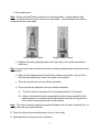
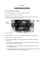
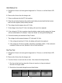
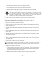
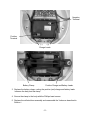
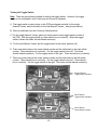
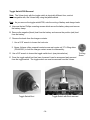
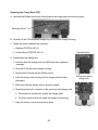
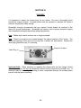
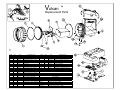
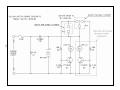
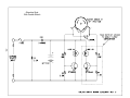
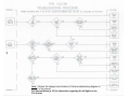
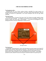
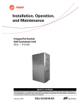
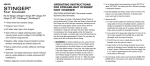
TABLE OF CONTENTS
PREFACE...................................................................................................……… -2TROUBLESHOOTING DIAGRAM..............................................................……… -3GENERAL NOTES......................................................................................……… -4SECTION I, REMOVING/REPLACING THE FACECAP ..........................……….. -5SECTION II, TESTING/REPLACING THE LAMP .....................………................. -6SECTION III, TESTING THE VULCAN BATTERY......................……………........ -8SECTION IV, TESTING/REPLACING THE SWITCH/PCB ASSEMBLY..……...... -12SECTION V, TESTING/REPAIRING THE CHARGER SYSTEM........….…………-22SECTION VI, THE BODY…………………………………………………………...…-29VULCAN REPLACEMENT PARTS AND DIAGRAM..................….....………........ -30VULCAN SWITCH/PCB SCHEMATIC………………………………………………..-31VULCAN CHARGE RACK PCB SCHEMATIC……………..………………………..-32FIRE VULCAN TROUBLESHOOTING DIAGRAM.....................................……….-34FIRE VULCAN GENERAL NOTES.............................................................……… .35TESTING/REPLACING THE SWITCH/PCB ASSEMBLY..…….................….....…-36FIRE VULCAN REPLACEMENT PARTS AND DIAGRAM..................….…..…….-42FIRE VULCAN SWITCH SCHEMATIC……………………………………….……….-43-
-1-
VULCAN SERVICE MANUAL
PREFACE
The purpose of this manual is to provide the information needed to service the Streamlight
Vulcan flashlight system.
This manual is dated (see front cover). Additions, deletions and changes to this manual
will display a later date.
A set of tools including a Phillips screwdriver, a #3 Tri-Wing driver, a 5/16” wrench,
needlenose pliers, a 15 ohm/10 Watt resistor, and a multimeter are required to service the
Vulcan.
Lamp may be changed without special tools.
For additional information and/or assistance contact:
STREAMLIGHT, INC.
Repair Department
30 Eagleville Road
Eagleville, Pa. 19403
Phone (610) 631-0600
Phone (800) 523-7488
FAX (610) 631-0712
7:00 a.m. - 5:00 p.m. EST
-2-
-3-
Note: A known Good Vulcan and Charge Rack will help to determine if the problem lies with the suspect Vulcan or the Charge Rack.
With no Vulcan in the suspect Charge Rack, and power applied, there should be no LED lighted. With a good Vulcan in the suspect Charge
Rack, and power applied, either the Red or the Green LED should be lighted; if not, the problem is most likely with the Charge Rack.
When a suspect Vulcan is discharged for several minutes and placed in a known good Charge Rack, if the Red LED does not light, the
problem is most likely with the Vulcan. Detailed testing instructions can be found in Section V on Page 18.
GENERAL NOTES
Troubleshooting Note
A troubleshooting diagram is provided (page 3) to help enable a repair technician to isolate
and repair electrical problems which can arise. The diagram describes a condition and
suggests the underlying cause. Repair procedures are provided in the chapters indicated
in the solution blocks. The troubleshooting procedure does not attempt to isolate individual
components. Instead it suggests replacement of modules or assemblies such as the
printed circuit board, the battery, etc. Occasionally problems may arise which are not
included in the troubleshooting procedure. In these cases a thorough physical inspection
may reveal a broken wire, cracked or damaged printed circuit board (PCB), or some other
mechanical damage which results in an apparent electrical problem. If the problem
remains elusive the Vulcan and all of its available components (including the charge rack
and plug-in wall transformer) should be returned to Streamlight for factory service.
Charge Contacts
The charge contacts located on the Vulcan and the charge rack must be kept clean. If the
charge rack contacts become dirty they can become stuck in the down position and fail to
make proper contact, resulting in the Vulcan not receiving a proper charge. If the contacts
become dirty they can be cleaned with a mild non-corrosive cleaner (WD-40). In extreme
cases, fouling can be removed by using a pencil eraser. Be careful not to remove the
protective plated surface of the charge contacts.
Charge Contacts
The Red and Green Charge Indicators
The Vulcan charge rack is equipped with two LED’s which light to indicate
the mode that the charging circuit is in. The red LED indicates that the
battery is being charged. The green LED indicates that the charging cycle is
complete and the battery is at maximum capacity.
The LED’s can warn of malfunctions within the charging circuitry. The red
LED should turn “off” completely twelve (12) hours or less after the charge
cycle is initiated and the green LED should turn “on”. If the red LED remains
on for more than 12 hours the charging circuit must be tested and repaired or replaced as
necessary (see section V).
-4-
SECTION I
REMOVING/REPLACING THE FACECAP
The facecap of the Vulcan is designed to prevent water from entering and damaging the
flashlight. A proper seal is achieved through the use of two internally mounted O-rings. It
is very important that the facecap be properly reinstalled after it has been removed.
Removal
A. Support the body of the Vulcan. The body should be placed in a bench mounted vise if
one is available with the facecap pointing upwards.
Note: Be sure to protect the body from damage.
B. Grasp the outside of the facecap and turn it counterclockwise until it comes free from
the Vulcan body.
Note: A strap wrench (minimum diameter 5 1/2 inches) will greatly facilitate removal of the
facecap.
Replacement
A. Support the body of the Vulcan as in step one above.
B. Thread the facecap onto the body and tighten the facecap to the point that you cannot
move the lens/reflector within the facecap.
C. Turn the facecap an additional 1/8th turn to insure its water resistance.
D. Inspect the area between the facecap and the lens to be sure that no portion of the
O-ring is showing. If the O-ring is showing remove the facecap and reinstall it as in
steps 1, 2, and 3 above.
O-ring must not
be showing.
-5-
SECTION II
TESTING/REPLACING THE LAMP
A. Remove the facecap from the Vulcan as described in Section I.
B. Carefully lift the lamp/reflector assembly away from the Vulcan body.
C. There are two different styles of bulbs. The single filament bulbs have two leads. Dual
filament bulbs have three leads.
Note: The single and dual filament bulbs are not interchangeable. Follow the instructions
below to test or replace the bulb.
1. Test the bulb.
Common Lead
Dual Filament
Single Filament
a. Unscrew the threaded bulb socket from the reflector.
b. Pull the old bulb straight out from the socket.
c. Use a multimeter in the continuity position.
(1). For single filament (bi-pin) bulbs place a meter lead on each bulb lead (a
beep or continuity indicates a good bulb).
(2). For dual filament bulbs (three pin) first establish the common lead (the
common lead connects with the long filament support visible inside the
bulb). Place one meter lead on the common lead and then test each of
the remaining leads (a beep or continuity indicates a good bulb).
-6-
2. Bulb replacement.
Note: Single and Dual filament bulbs are not interchangeable. A single filament bulb
socket is connected to the circuit board by two wire leads. A dual filament bulb socket is
connected by three wire leads.
Dual Filament Socket
Single Filament Socket
a. Replace the bulb by aligning the pins with the holes in the socket and seat the
bulb firmly.
Note: Use care and make sure that the leads are properly aligned when inserting the dual
filament bulb.
b. Wipe off any fingerprints from the bulb with a tissue and alcohol. Any oil left on
the bulb will permanently “smoke” the inside of the reflector.
c. Screw the socket back into the reflector assembly.
d. The socket can be adjusted in the spot reflector assembly.
(1). Turn the Vulcan on and shine it on a wall approximately 10 feet away.
(2). Adjust to the desired focus by screwing the socket inward towards the fully
seated position or outwards until the point where the socket O-ring starts to
leave the surrounding screw shell of the reflector.
Note: The focus should be attained somewhere between the two limits described (try 1/4
turn out from the fully seated position).
D. Place the reflector/lens assembly back into the Vulcan body.
E. Reassemble the Vulcan as shown in Section I.
-7-
SECTION III
TESTING/REPLACING THE BATTERY
Test for Charge Power to the Battery
A. Remove the facecap from the Vulcan as described in Section I.
B. Place a multimeter into the DC Volts position.
C. Place the red meter lead onto the positive (red) battery terminal and the black meter
lead onto the negative (black) battery terminal.
Negative
Terminal
Positive
Terminal
D. Note the voltage.
E. Place the Vulcan into a known good charge rack, and connect it to a power supply.
F. Allow the Vulcan to charge for 5 minutes.
G. Leave the Vulcan charging in the charge rack and re-test the battery as described in
Step C above.
H. The voltage of the battery while charging in the charge rack should be at least .20 Volts
above the voltage noted in Step D above.
1. If the voltage is at least .20 Volts greater than the voltage noted in Step D, proceed
to the Quick Battery Test.
2. If the voltage is less than .20 Volts greater than the voltage noted in Step D, proceed
to Testing the Printed Circuit Board, located in Section IV.
-8-
Quick Battery Test
A. Charge the Vulcan in a known good charge rack for 12 hours, or until the Green LED
lights.
B. Remove the Vulcan from the charge rack.
C. Place a multimeter into the DC Volts position.
D. Place the red meter lead onto the positive (red) battery terminal and the black meter
lead onto the negative (black) battery terminal.
E. The voltage should measure above 6.5 Volts.
F. If the voltage is less than 6.5 Volts, the battery will need to be replaced.
G. If the voltage is 6.5 Volts or greater, place the battery under load by running the Vulcan
with a six-watt bulb for 10 minutes. Leave the Vulcan ‘on’ during the following test.
H. Re-test the battery as described in Step C above.
I. The voltage should measure between 6.0 Volts and 6.4 Volts.
1. If the voltage is less than 6.0 Volts, the battery will need to be replaced.
2. If the voltage is 6.0 Volts or greater, the battery is probably usable. If the customer’s
complaint is short run time, proceed to the run time test below.
Run Time Test
A. Charge the Vulcan in a known good charge rack for 12 hours, or until the Green LED
lights.
B. Remove the Vulcan from the charge rack.
C. Turn the Vulcan ‘on’ and note the run time. Also observe the lamp intensity.
1. Run time is the time from when the Vulcan is turned on to the point where it
becomes no longer usable.
2. Nominal run times and charge times are listed below.
Lamp Option
3 watt spot
6 watt spot
8 watt spot
Run Time
6.75 hrs.
3.75 hrs.
2.75 hrs.
Charge Time (AC)
12.0 hrs.
12.0 hrs.
12.0 hrs.
-9-
Charge Time (DC)
10 hrs.
10 hrs.
10 hrs.
3. Normal intensity and short run time may indicate sulfation.
4. Low intensity and normal run time may indicate shorted cells.
5. Batteries which exhibit signs of sulfation or shorted cells must be replaced.
Pb
The sealed lead acid battery in this product is recyclable. At the end of its useful
life, under various state laws, it may be illegal to dispose of this battery in the
municipal solid waste stream. Check with your local solid waste officials for
details in your area for recycling options or proper disposal.
D. If the Vulcan has normal intensity and normal run time the battery is good.
Removing and Replacing the Vulcan Battery (See pictures on Page 11.)
A. Remove the facecap as described in Section l.
B. Place the Vulcan on a table or bench with the open end facing upwards and with the
handle away from you.
C. Carefully lift the reflector/lens assembly from the body and unscrew it from the lamp
socket.
D. Unscrew the Phillips head screws on each side of the battery clamp and remove the
battery clamp.
E. Carefully disconnect the battery leads. (Use needle-nose pliers if necessary.) Move
the battery leads aside.
F. Move the charge leads aside enough to allow the battery to pass. Do not disconnect
the charge leads.
G. Carefully pull the battery from the Vulcan body.
Note: Always handle the battery with care and do not allow it to become short-circuited. A
short-circuited battery can deliver hundreds of amperes of current, which can start a fire.
H. Install the new battery in the Vulcan.
1. Place the battery, terminal side up, into the Vulcan body. Position the battery with
the negative (black) terminal closest to the Printed Circuit Board, and the positive
(red) terminal closest to the charge contacts.
2. Attach the battery leads to the battery terminals, observing proper polarity.
- 10 -
Negative
Terminal
Positive
Terminal
(–)
(+)
Charge Leads
Battery Clamp
Positive Charge and Battery Leads.
3. Replace the battery clamp, routing the positive (red) charge and battery leads
between the body and the clamp.
4. Secure the clamp to the body with the Phillips head screws.
5. Replace the reflector/lens assembly and reassemble the Vulcan as described in
Section I.
- 11 -
SECTION IV
TESTING/REPLACING THE SWITCH/PCB ASSEMBLY
Note: There are currently several different switch versions. The instructions for
checking the PCB are the same for all versions. The different switches are
addressed individually in this chapter.
Testing the Printed Circuit Board Charge Circuit
A. Remove the facecap from the Vulcan as described in Section I.
B. Place the Vulcan on a table or bench with the open end facing upwards and with the
handle away from you.
C. Unscrew and remove the reflector assembly from the lamp holder and place the
assembly aside.
D. Disconnect the negative (black) battery lead. (See pictures on Page 11).
E. Place a multimeter into the Continuity Check position.
F. Place one meter lead onto the negative charge contact, and the other meter lead onto
the negative (black) battery lead. The meter should indicate continuity.
G. Place a multimeter into the Diode Check Position.
H. Place the positive (red) meter lead onto the positive (red) charge contact. Place the
negative (black) meter lead onto the positive (red) battery terminal. The meter should
read between .5 and .7 Volts. (Continuity through a diode junction.)
I. Place the negative (black) meter lead onto the positive (red) charge contact. Place the
positive (red) meter lead onto the positive (red) battery terminal. The meter should read
Over Range. (Open circuit across reversed diode junction.)
J. Set a multimeter to the ohms position.
K. Place one meter lead onto the positive charge contact, and the other meter lead onto
the negative charge contact. The meter should read between 1.76 and 2.64 K ohms.
L. If the switch/PCB fails any of the above tests it must be replaced.
M. If the switch/PCB passes these tests, the lamp is good, the battery is good, and the
Vulcan still does not light: If the Vulcan has a toggle switch, replace the board. If
the Vulcan has the older style ‘C’ shaped contact, check the switch contact on the
printed circuit board. (See page 19.)
- 12 -
Testing the Toggle Switch
Note: There are procedures included for testing the toggle switch. However, the toggle
switch is not serviceable, and if it fails any test it must be replaced.
A. The toggle switch contact points on the PCB are aligned vertically for the single
filament Vulcan, and horizontally on the dual filament Vulcan. (see pictures below.)
B. Place a multimeter into the Continuity Check position.
C. For the single filament Vulcan, place one meter lead on each toggle switch contact of
the PCB. With the toggle switch up, there should be no continuity. When the toggle
switch is down the meter should indicate continuity.
D. For the dual filament Vulcan, put the toggle switch in the center position (off).
E. Place one meter lead on the center switch contact and the other lead on the right switch
contact. There should be no continuity. Put the toggle switch to the left. The meter
should indicate continuity. Put the toggle switch to the right. There should be no continuity.
F. Place one meter lead on the center switch contact and the other lead on the left switch
contact. There should be no continuity. Put the toggle switch to the left. There should
be no continuity. Put the toggle switch to the right. The meter should indicate continuity.
Single Filament
Toggle Switch Contacts
Dual Filament
Toggle Switch Contacts
Dual Filament
Center Switch Contact
- 13 -
Toggle Switch/PCB Removal
Note: The Vulcan body with the toggle switch is physically different from, and not
interchangeable with, the Vulcan body using the paddle switch.
Note: As you remove the toggle switch/PCB, note the routing of battery and charge leads.
A. Unscrew the two Phillips mounting screws which secure the battery clamp and remove
the battery clamp.
B. Remove the negative (black) lead from the battery and remove the positive (red) lead
from the battery.
C. Remove the leads from the charger contacts.
1. Use a 5/16" wrench to loosen the lock-nuts.
2. Newer Vulcans utilize a special contact screw and require a # 3 Tri-Wing driver
(P/N 440051) to hold the charger contact screw for disassembly.
D. Use a 5/8” wrench to loosen the toggle switch boot. (see picture below)
E. Once the toggle switch boot has been loosened it can be unscrewed and removed
from the toggle switch. The toggle switch can now be removed from the Vulcan.
Toggle Switch Boot
Toggle Switch with Boot removed
- 14 -
Tri-Wing
Screw
Toggle Switch/PCB Installation
A. Obtain a replacement toggle switch/PCB assembly.
Single Filament Assembly P/N 440118
Dual Filament Assembly P/N 440119
This nut must be bottomed on the threads. Do not over tighten.
B. Reattach the leads to the charge contact screws and secure them in place.
1. The negative (black) lead goes to the charge contact screw on the left side (open
side of body facing upward, handle facing away from you) and the positive (red)
charge lead goes to the contact screw on the right.
2. Use a 5/16" wrench to tighten the lock nuts until they are snug against the body.
When the contact screws are snug turn the Tri-Wing contact screw additional 1/8th
turn to insure a waterproof seal.
Note: Do not over tighten the screws or the body may crack.
C. Place the toggle switch/PCB assembly with the toggle switch through the switch hole.
1. The Toggle switch side of the assembly must face down. (See picture below)
Positive Battery
and Charge Leads
Negative
Charge Lead
- 15 -
2. Route the battery leads and charge leads between the mounting posts and the walls
of the body.
3. Reconnect the battery leads and test the switch for function. After confirming the
switch functions properly, remove the battery leads and proceed to Step D
D. Replace the battery clamp above the battery, but do not secure it.
1. Route the positive battery and charge leads between the Vulcan body and the
battery clamp on the right side of the Vulcan (handle facing away from you).
2. Route the negative charge lead (only) between the Vulcan body and the battery
clamp on the left side of the Vulcan (handle facing away from you).
E. Secure the battery clamp into place with the two Phillips mounting screws.
F. Reattach the battery leads.
1. Attach the positive (red) lead to the positive battery terminal. (Note: Use needlenose
pliers if necessary.
2. Attach the negative (black) lead to the negative battery terminal.
G. Place the lamp into the lamp socket (Note: Detailed instructions are in Section ll).
H. Put the switch boot over the toggle switch and, using a 5/8” wrench, carefully tighten it
until it is snug.
I. Reassemble the Vulcan as described in Section l.
Toggle Switch with Boot
(Before Tightening)
Toggle Switch without Boot
- 16 -
Testing the Paddle Switch Contacts
Note: Replacement parts for the Paddle Switch versions are no longer available. If
adjusting the switch contacts does not fix the problem, the entire Body/PCB
assembly must be replaced.
A. Reconnect the negative (black) battery lead.
B. Remove the two mounting screws which hold the switch/PCB assembly in-place.
Remove mounting screws.
Insulating Washer
(Under Screw Head)
Note: There is a washer on the mounting screw located below the positive leads. This
screw and insulating washer combination is critical and must be retained for reassembly.
C. Carefully lift the switch/PCB from the mounting posts and tilt it towards you.
D. At the front of the switch/PCB is a “U” shaped contact. Press the raised left end of the
contact against the pad of the PCB. The lamp should light.
Raised ends of the contact.
E. Repeat the process using the raised right end of the contact. The lamp should light.
F. If the lamp does not light, the switch/PCB must be replaced.
G. If the lamp does light, the “U” shaped contact on the PCB may need to be adjusted.
H. Remove the switch/PCB from the Vulcan and follow the procedures on page 18.
- 17 -
Paddle Switch/PCB Removal
Note: As you remove the switch/PCB, note the routing of battery and charge leads.
A. Unscrew the two Phillips mounting screws which secure the battery clamp and remove
the battery clamp.
B. Remove the negative (black) lead from the battery and remove the positive (red) lead
from the battery.
C. Remove the leads from the charger contacts.
1. Use a 5/16" wrench to loosen the lock-nuts.
2. Newer Vulcans utilize a special contact screw and require a # 3 Tri-Wing driver
(P/N 440051) to hold the charger contact screw for disassembly.
Note: Original Vulcans used hex contact screws. (See page 32) These screws are
not interchangeable. Tri-Wing screws CANNOT be used on the older Vulcans.
Tri-Wing
Screw
D. Lift and remove the switch/PCB assembly and associated leads from the Vulcan body.
E. Check the Phillips screw which secures the switch actuator. Tighten if necessary.
Insure screw is tight.
Adjusting the Contacts
A. Remove the switch/PCB from the Vulcan as described above.
B. Place the short end of a 1/16” Allen wrench under the raised portion of the “U” shaped
contact. (See pictures on page 19).
C. Hold the end of the contact against the PCB.
D. Slowly rock the Allen wrench until the contact bends slightly upward above the wrench.
E. Repeat the procedure for the other end of the contact.
- 18 -
F. Inspect the ends of the contact to insure that they are not touching the pads on the
PCB. The ends should be about 1/32” above the board.
Note: There is a somewhat critical relationship between the ends of the contact, the bends
in the contact, and the circuit board. The switch actuator presses against the contact at the
spot where you bend it upward. The ends of the fingers are pressed down against the
PCB. If the ends of the fingers are too high, or the contact bend is too low, the lamp will
not turn on. If the ends are set too low, they may fatigue over time and not turn off.
If you are unable to obtain proper operation by adjusting the contacts, you will need to
replace the entire Vulcan Body/Switch assembly.
Insert short end of
1/16 Allen wrench
under contact here.
Hold the end of
the contact down
while “bending” it.
Allen wrench
Hold the end of
the contact down
while “bending” it.
Ends of the contact should be
about 1/32” above the PCB.
- 19 -
Paddle Switch/PCB Installation
Single Filament Assembly P/N 440008
Dual Filament Assembly P/N 440027
B. Reattach the leads to the charge contact screws and secure them in place.
1. The negative (black) lead goes to the charge contact screw on the left side (open
side of body facing upward, handle facing away from you) and the positive (red)
charge lead goes to the contact screw on the right.
2. Use a 5/16" wrench to tighten the lock-nuts until they are snug against the body.
When the contact screws are snug turn the Tri-Wing contact screw additional 1/8th
turn to insure a waterproof seal.
Note: Do not over tighten the screws, especially the older style hex screws, or the body
may crack.
C. Place the switch/PCB assembly onto the mounting posts in the Vulcan body.
Mounting Posts
1. The switch contact side of the assembly must face down. See picture on page 21
for proper orienteering.
2. Route the battery leads and charge leads between the mounting posts and the walls
of the body.
- 20 -
Positive Battery
and Charge Leads
Negative
Charge Lead
3. Align the holes in the switch/PCB with the mounting standoffs and secure the
assembly with the Phillips screws. (Note: Insure that there is an insulating washer
under the head of the mounting screw located on the side with the positive leads.
4. Reconnect the battery leads and test the switch for function. After confirming the
switch functions properly, remove the battery leads and proceed to Step D. If the
switch does not function properly, readjust the contacts as described on page 19.
D. Replace the battery clamp above the battery, but do not secure it.
1. Route the positive battery and charge leads between the Vulcan body and the
battery clamp on the right side of the Vulcan (handle facing away from you).
2. Route the negative charge lead (only) between the Vulcan body and the battery
clamp on the left side of the Vulcan (handle facing away from you).
E. Secure the battery clamp into place with the two Phillips mounting screws.
F. Reattach the battery leads.
1. Attach the positive (red) lead to the positive battery terminal. (Note: Use needlenose
pliers if necessary.
2. Attach the negative (black) lead to the negative battery terminal.
G. Place the lamp into the lamp socket (Note: Detailed instructions are in Section ll).
H. Reassemble the Vulcan as described in Section l.
- 21 -
SECTION V
TESTING/REPAIRING THE CHARGER SYSTEM
The Vulcan currently has two charge racks available, a “direct wire” with a permanently
attached 12 V DC power cord, and a “standard” rack with a socket that accepts a variety of
charge cords for various DC and AC power sources.
Note: All power sources must provide the charge rack with 12 - 15 V DC during charging.
AC Chargers will read between 13 and 22 Volts under no load conditions, depending upon
your transformer. DC Vehicle System Charge cords will read between 11 and 15 Volts, the
normal voltage of the vehicle.
Testing the AC Wall Charger
A. The AC wall charger can be tested by simply measuring its output voltage.
B. Make sure that the wall charger is plugged into a functioning
AC outlet.
C. Place a multimeter in the DC volts position.
D. Hold the charge connector facing towards you, with the black key
at the top of the connector (see illustration).
1. Place the positive lead of the meter onto the left pin of the
connector.
2. Place the negative meter lead on the right pin.
E. The meter should give a reading between 13 and 22 volts and there must be no
indication of reversed polarity.
F. If the voltage or polarity is wrong replace the charger.
G. Do not attempt to repair the AC charger.
Testing the DC-1 Charge Cord (Cigarette Lighter Plug)
A. Connect the DC-1 charger plug to its power source (power point, cigarette lighter
adapter, etc...).
B. Place a multimeter into the DC Volts position.
- 22 -
C. Measure the voltage as in Step D on page 22 (AC testing).
D. The meter reading must reflect the vehicle’s supply voltage and be between 11 and 15
Volts DC.
1. If there is no reading the charge cord needs to be checked.
a. Place the multimeter into the continuity test position and place one meter lead
onto the right charge connector pin (with the connector facing you, key on top).
b. Place the other meter lead onto the ground spring on the cigarette lighter plug.
c. The meter should indicate continuity.
d. Place one meter lead on the left charge connector pin (connector facing you, key
on top).
e. Place the other meter lead onto the tip of the cigarette lighter plug.
f. The meter should indicate continuity. If it does not, check the fuse.
(1). Remove the fuse by removing the end of the cigarette lighter plug.
(Push and twist the end cap.)
(2). Test the continuity of the fuse.
(3). If required, replace the fuse with a 20mm X 5 mm fuse (2 amp slow-blow, 2
amp fast-blow, or 5 amp fast blow).
g. If there is no continuity (complete circuit) in Step 1c above, or after replacing the
fuse, the DC-1 should be replaced.
2. If the meter shows proper voltage, proceed to Testing the Charge Rack below.
Testing the Charge Rack
The 12V DC direct wire charge rack has a permanently wired cord to supply input power.
If possible the direct wire charge rack should be checked while it is connected to its power
source (a known good 12V DC source is also suitable).
Note: Direct Wire Systems must be connected to the vehicle battery through either a
switched or un-switched connection. Streamlight recommends that Direct Wire Systems
not be connected to the accessory rail of a “battery saver” or supplemental charger. Some
such devices can destroy the Vulcan charge circuitry and will void the warranty.
- 23 -
A. Connect the charge rack to its power supply. (Direct wire rack connected to vehicle
battery; Standard rack connected to a known good power supply).
B. Measure the charge rack output at the charge pins at the front of the charge rack.
1. Place the positive meter lead on the charge pin located closest to the Red and
Green LEDs.
2. Place the negative meter lead onto the other charge pin.
Charge Pins
Positive
Negative
3. The meter should show the supply voltage (11 to 22 volts).
a. If there is no voltage or reverse voltage check the wiring between the rack and
the supply (also check any in-line fuse).
b. If there is no reading the charge rack internal wiring needs to be checked.
(See below for testing procedures.)
Testing the Internal Wiring
A. Turn the charging rack over to expose its base plate.
B. Place a small flat screwdriver blade between the external power connector or strain
relief lug (direct-wire version) and apply a small amount of pressure. (See picture on
Page 25.)
- 24 -
C. Compress the mounting posts and remove the base plate of the charging rack.
Mounting Posts
Key Slot
D. The power input connector has a key slot that faces toward the base plate of the rack.
1. Testing the standard power input connector. (See pictures on Page 26.)
a. Place the charge rack with the charge contacts down and the power input
connector to the right.
b. Place a multimeter into the continuity mode.
c. Place one meter lead into the right-hand (positive) contact of the power input
connector.
d. Place the other meter lead onto the solder pad where the positive (red) lead is
connected to the charge rack PC Board.
e. The meter should indicate continuity.
f. Follow the same procedure using the negative contact of the power input
connector and the solder pad where the negative(black) lead is connected to
the charge rack PC Board.
g. If the meter does not indicate continuity, and no obvious repairable problems are
evident (broken solder joints, etc…), the PCB assembly will need to be replaced.
The power input cord is not available separately.
- 25 -
Positive contact
(PC Board)
Negative contact
Positive contact
(Power Input)
2. Testing the Direct Wire power input leads.
Note: Disconnect charge racks with permanently wired input power from the input source.
a. Disassemble the charge rack as directed on page 24, Testing the Internal Wiring.
b. Place a multimeter into the continuity position.
c. Place one meter lead on the positive power input lead (red stripe).
d. Place the other meter lead onto the solder pad where the positive power lead is
connected to the Printed Circuit Board.
e. The meter should indicate continuity.
f. Follow the same procedure using the negative lead and the other solder pad.
g. If the meter does not indicate continuity, and no obvious repairable problems are
evident (broken solder joints, etc…), the PCB assembly will need to be replaced.
The power input cord is not available separately.
- 26 -
Testing For Proper Charge Rack Function
A. Use a known good Vulcan to test the charge rack.
B. Remove the facecap from the Vulcan as described in Section I.
C. Unscrew and remove the lens/reflector assembly from the lamp holder.
D. Remove the negative lead (black) from the negative battery terminal and remove the
positive lead (red) from the positive battery terminal.
E. Place the known good Vulcan into the charge rack to be tested.
F. Insure the charge rack is connected to a known good power source.
1. If the green LED is lighted and the red LED is off follow the test procedures below.
a. Set the multimeter to the DC volts position.
b. Place the positive meter lead on the red battery lead.
c. Place the negative meter lead on the black battery lead.
d. The meter should read between 7.1 and 7.4 volts.
(1). The green LED should be on.
(2). The red LED should be off.
e. Keep the multimeter connected to the battery leads.
(1). Place a 15 ohm/10 watt resistor across the battery leads.
(2). The multimeter should read between 6.65 and 6.95 volts.
(3). The green LED should be off.
(4). The red LED should be on.
(5). If the PC board performs as outlined in the steps above it is functional.
(Reassemble the Vulcan as shown in Section I).
(6). If the PC board did not perform satisfactorily it should be replaced.
2. If the red LED is lighted, both LED's are lighted, or neither LED is lighted, the
circuit board should be replaced.
- 27 -
Replacing the Charge Rack PCB
A. Unscrew the Phillips head screw located above the single base plate mounting post.
Mounting Screw
B. Carefully lift the PCB assembly straight up and out of the charger housing.
C. Obtain the proper replacement assembly.
1. Standard PCB P/N 440115.
Standard Rack.
2. Vehicle Mount PCB P/N 440114.
D. Reassemble the charge rack.
1. Carefully align the charge pins and LED's with their respective
openings.
2. Seat the PC Board in the charger housing.
3. Secure the PC Board with the Phillips screw.
4. Hold the charger rack housing with the charger latch pointing
downward.
Rib must be inside
charge rack.
5. Make sure that the charger latch is properly seated.
6. Place the power input connector in the opening in the charger rack.
a. The keyed slot should point toward the charger base.
b. The strain relief rib must be inside the charge rack opening.
7. Align the bottom cover and snap it into place.
Direct Wire Rack.
- 28 -
SECTION VI
THE BODY
It is important to inspect the Vulcan body for any cracks. Be sure to thoroughly check
around the charge contacts. Cracked bodies must be replaced to maintain the Vulcan's
hermetic integrity and safety ratings.
Streamlight strongly recommends that any cracked Vulcan bodies be returned to the
factory for proper replacement. Streamlight will vacuum test for proper hermetic integrity
and compliance with applicable safety rating requirements.
Note: Paddle style switch versions are no longer available.
Note: There is a pressure vent located between the charge contacts of the Vulcan. The
very small opening of this vent must be kept free of debris, dirt and residue. Replace the
valve plug (protective cap) if it is missing.
Check for Cracks.
Valve Plug
Important Note: When mounting or repairing the charge rack and the charge contact
screws in the body, Do Not Use anaerobic thread locking compounds (Loctite®, etc). A
chemical reaction caused by the curing of these compounds destroys the molded plastic
and will void the factory warranty.
- 29 -
Vulcan
Replacement Parts
- 30 ITEM
1
2
3
4
5
6
7
8
9
QTY
1
1
1
2
1
1
1
1
1
1
10
11
1
1
12
13
1
1
14
15
1
2
17
18
1
1
P/N
440002
440033
440070
440023
440005
440006
44007
440116
440116-1
440008
440027
440046
44913
44912
44009
44012
44013
45232
440018
400262
440015
130018
DESCRIPTION
FACE CAP
O-RING, FACE CAP
REFLECTOR/LENS ASSY.
SCREW, BATTERY CLAMP
CLAMP, BATTERY
PAD, BATTERY CLAMP
BATTERY
BOOT, SWITCH
BOOT, D.F. SWITCH (GREY)
PCB ASSY, STD TOGGLE
PCB ASSY, D.F. TOGGLE
O-RING, BODY
BULB, 8W BI-PIN
BULB, 6W DUAL FILAMENT
KIT, CONTACT SCREW
KIT, SWITCH MECH W/LOCK
KIT, SWITCH (SHOWN)
STRAP ASSY, SHOULDER
CLIP, SHOULDER STRAP
D-RING (NEW STYLE)
(OLD STYLE - NOT SHOWN)
PLUG, VALVE
VALVE
ITEM
19
20
QTY
1
1
1
21
22
23
1
1
1
24
25
1
1
22311
21725
22666
22241
22051
440040
440040-6
P/N
440040
440040-6
440102
440102-6
450022
900047
440115
440114
440106
440101
440101-6
DESCRIPTION
BODY/HANDLE ASSY., YELLOW
BODY/HANDLE ASSY., GREEN
COVER, CHARGE RACK YELL.
COVER, CHARGE RACK GRN
SPRING, LATCH RELEASE
SCREW, 4-24 X 1/2 PHILLIPS
PCB, STANDARD
PCB, VEHICLE MOUNT
LATCH, CHARGER
HOUSING, CHARGER YELLOW
HOUSING, CHARGER GREEN
NOT SHOWN:
CORD, 120V AC CHARGE
CORD, 230V AC CHARGE
CORD, 100V AC CHARGE
CORD, 240V AC CHARGE
CORD, 12V DC CHARGE
BODY/HANDLE ASSY., YELLOW
BODY/HANDLE ASSY., GREEN
- 31 -
Obsolete Style
With Paddle Switch
- 32 -
-33 -
- 34 Note : Review the charger note at bottom of Vulcan troubleshooting diagram on
page 3 of this manual.
See General Notes (p. 35) for information regarding the tail lights on the
Fire Vulcan
FIRE VULCAN GENERAL NOTES
Troubleshooting Note
Troubleshooting the Fire Vulcan system involves essentially the same process as
troubleshooting the standard Vulcan system. Most repair issues (except the battery, lamp and
charger) will require the replacement of the entire switch/pcb and LED tail light board
assembly.
Tail Light Lenses
The tail light lenses on the rear of the body of the Fire Vulcan are sonically welded in place
and are not field serviceable. The integrity of the lenses must be maintained to assure the
hermetic integrity and class rating of the flashlight. If the lenses are damaged the entire
flashlight should be returned to Streamlight for factory service.
Tail Light Lenses
Tail Light Issues
If the taillights operate improperly or fail to light the wiring connection between the tail light PC
boards and the switch/PC board should be inspected. If the connections are intact and the tail
light PC boards are in place there may be a misplaced switch/PC board jumper. See the
jumper position table on page 43 for the correct positioning of each jumper. If the problem
persists the entire switch/PC board and tail light PC board will need to be replaced (p.38).
- 35 -
TESTING/REPLACING THE SWITCH/PCB ASSEMBLY
Testing the Printed Circuit Board Charge Circuit
A. Remove the facecap from the Vulcan as described in Section I (page 5).
B. Place the Vulcan on a solid work surface with the open end facing upwards and with the
handle away from you.
C. Unscrew and remove the reflector assembly from the lamp holder. Place the
assembly aside.
D. Disconnect the positive and negative battery leads.
E. Place a multimeter into the Continuity Check position.
F. Place one meter lead onto the negative charge contact, and the other meter lead onto
the negative (black) battery lead. The meter should indicate continuity.
G. Place a multimeter into the Diode Check Position.
H. Place the positive (red) meter lead onto the
positive (red) charge contact. Place the
negative (black) meter lead onto the positive
(red) battery lead. The meter should
read between .5 and .7 Volts. (Continuity
through a diode junction.)
I. Place the negative (black) meter lead onto the
positive (red) charge contact. Place the
positive (red) meter lead onto the positive (red)
battery lead. The meter should read
Over Range (Open circuit across reversed
diode junction).
( - ) Charge
Contact
( + ) Charge
Contact
J. Set a multimeter to the ohms position.
K. Place one meter lead onto the positive charge contact, and the other meter lead onto
the negative charge contact. The meter should read between 1.76 and 2.64 K ohms.
L. If the switch/PCB fails any of the above tests it must be replaced (proceed to p.38).
- 36 -
Testing the Toggle Switch
Note: There are procedures included for testing the toggle switch. However, the toggle switch
is not serviceable, and if it fails any test it must be replaced.
A. Disconnect the negative (-) battery lead.
B. Note the location of the toggle switch contacts in the photo below.
C. Place a multimeter into the Continuity Check position.
D. Place the toggle switch in the center position (off).
E. Place one meter lead on the center switch contact and the other lead on the right switch
contact. There should be no continuity. Push the toggle switch to the left. The meter
should indicate continuity. Push the toggle switch all the way to the right. There should
be no continuity.
F. Place one meter lead on the center switch contact and the other lead on the left switch
contact. There should be no continuity. Push the toggle switch to the right. The meter
should indicate continuity. Push the toggle switch all the way to the left. There should
be no continuity.
Center Switch Contact
Toggle Switch Contacts
- 37 -
Toggle Switch/PCB Removal
Note: As you remove the toggle switch/PCB, note the routing of battery and charge leads.
A. Unscrew the two Phillips mounting screws which secure the battery clamp and remove
the battery clamp.
Negative
Battery
Lead
Battery
Clamp
Positive
Battery
Lead
Battery Clamp
Screws
Charge Contacts and
Lock Nuts
B. Remove the negative (black) lead from the battery and remove the positive (red) lead
from the battery.
C. Remove the battery from the flashlight body.
D. Remove the leads from the charge contacts.
1. Fire Vulcans utilize a special contact screw and require
a # 3 Tri-Wing driver (P/N 440051) to hold the charge contact
screw for disassembly.
2. Use a 5/16" wrench to loosen the lock nuts.
- 38 -
Tri-Wing
Screw
E. Unscrew the Phillips mounting screws that secure the LED tail light boards to
the flashlight body.
LED tail light board screws
F. Use a 5/8" wrench to loosen the toggle switch boot (see picture below).
Toggle Switch Boot
G. Once the toggle switch boot has been loosened it can be unscrewed and removed
from the toggle switch. The toggle switch/PCB and LED tail light boards can now be
removed from the Vulcan.
- 39 -
Toggle Switch/PCB Installation
A. Obtain a replacement LED toggle switch assembly p/n: 440127
( - ) Negative Charge
Lead
( - ) Negative Battery
Lead
LED Tail Light
Boards
( + ) Positive Battery
Lead
( + ) Positive Charge
Lead
B. Place the entire assembly into the flashlight body.
1. Guide each of the tail light LED’s into the openings for the tail light lenses.
2. Guide the toggle switch handle through the opening in the flashlight body and seat the
PC board with the lamp leads, charge leads, and battery leads facing toward the
mounting holes for the charge contacts.
3. Align the mounting brackets of the LED tail light boards with the guides molded into the
top opening of the flashlight body.
a. Route the charge and battery leads over the LED tail light board leads.
b. Fasten each LED tail light board mounting bracket to the body with a # 1 Phillips
screw and tighten.
- 40 -
C. Place the toggle switch boot nut over the switch handle and tighten the nut with a 5/8”
wrench. Note: Do Not Over Tighten the Nut.
D. Insert the battery into the body of the flashlight. The battery terminals should be pointing
upward and the positive battery contact should be adjacent to the charge contact mounting
holes.
E. Reconnect the battery leads and test the switch for function. After confirming the
switch functions properly, remove the battery leads.
F. Reattach the charge leads to the charge contact screws and secure them in place.
1. The negative (black) lead goes to the charge contact screw on the left side (open
side of body facing upward, handle facing away from you) and the positive (red)
charge lead goes to the contact screw on the right.
Charge Contacts
2. Use a 5/16" wrench to tighten the lock nuts until they are snug against the body.
When the contact screws are snug turn the Tri-Wing contact screw an additional 1/8th
turn to insure a waterproof seal.
Note: Do not over tighten the screws or the body may crack.
G. Place the battery clamp on the battery, but do not secure it in place.
1. Route the positive battery and charge leads between the Vulcan body and the
battery clamp on the right side of the Vulcan (handle facing away from you).
2. Route the negative charge lead (only) between the Vulcan body and the battery
clamp on the left side of the Vulcan (handle facing away from you).
H. Secure the battery clamp into place with the two Phillips mounting screws.
I. Reassemble the Vulcan as described in Section l.
- 41 -
FIRE VULCAN
REPLACEMENT PARTS
- 47 - 42 -
Jumper A
Jumper B
- 43 -