1
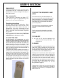
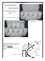
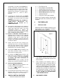
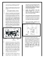
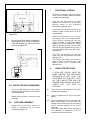
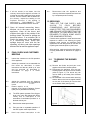
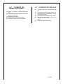
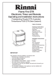
Mystique ECO 4 REMOTE DECORATIVE FUEL EFFECT APPLIANCE THIS IS NOT A “DO-IT-YOURSELF” PRODUCT THIS IS A NATURAL GAS (G20) APPLIANCE FOR USE IN GB AND IE ONLY AT A SUPPLY PRESSURE OF 20mbar. USER’S, INSTALLATION AND SERVICE MANUAL PLEASE KEEP THESE INSTRUCTIONS IN A SAFE PLACE FOR FUTURE REFERENCE Our policy is one of constant development and improvement. Strict accuracy of illustrations and specifications is not guaranteed. Modifications to design and materials may be necessary subsequent to publication. V.11.07 TABLE OF CONTENTS IMPORTANT NOTES USER’S SECTION _________________________________ ___________________ 4 FUEL EFFECT ________________________________________ GAS CONSUMPTION______________________________________ OPERATING INSTRUCTIONS __________________________________ TO LIGHT THE FIRE ______________________________________ TO SELECT THE REQUIRED FLAME LEVEL _______________________ 4 TO TURN OFF ________________________________________ CLEANING __________________________________________ OXYGEN DEPLETION SYSTEM _________________________________ FUEL BED ASSEMBLY _____________________________________ INSTALLATION SECTION ________________ 7 1 GENERAL DATA _____________________________________ GENERAL INSTALLATION REQUIREMENTS ___________________ 7 3 CHECK CARTON CONTENTS _______________________________ 4 THE FIREPLACE _____________________________________ 5 GAS SUPPLY PIPE ____________________________________ 6 APPLIANCE INSTALLATION _______________________________ 6.8 CHECK FOR GAS SOUNDNESS____________________________ 10 6.9 FUEL BED ASSEMBLY ___________________________________ 7 FUNCTIONAL CHECKS ___________________________________ 8 CHECK FOR SPILLAGE ___________________________________ 9 FINAL CHECK AND CUSTOMER BREIFING ___________________ 11 10 SERVICING ________________________________________ 10.1 TO REMOVE THE BURNER UNIT ___________________________ 11 10.2 TO REMOVE THE THERMOCOUPLE ASSY. ___________________11 10.3 TO REMOVE THE GAS VALVE _____________________________ 12 12 FAULT FINDING ______________________________________ 2 2 V.11.07 IMPORTANT NOTES IMPORTANT: PLEASE READ ALL OF THE INSTRUCTIONS IN THIS BOOKLET BEFORE COMMENCING INSTALLATION AS FAILURE TO COMPLY WITH THE REGULATIONS HEREIN COULD LEAD TO PROSECUTION & INVALIDATE THE WARRANTY 1. 2. SOFT WALL COVERINGS, (e.g. EMBOSSED VINYLS etc.) WHICH HAVE A RAISED PATTERN, ARE EASILY AFFECTED BY HEAT AND MAY SCORCH OR BECOME DISCOLOURED WHEN CLOSE TO A HEATING APPLIANCE. PLEASE BEAR THIS IN MIND WHEN RE-DECORATING. 7. 8. AS WITH ANY GAS FIRE, THIS APPLIANCE MUST BE INSTALLED BY A COMPETENT PERSON (e.g. IN GB A C.O.R.G.I. MEMBER) IN ACCORDANCE WITH THE INSTALLATION INSTRUCTIONS AND THE LATEST EDITION OF THE GAS SAFETY (INSTALLATION AND USE) REGULATIONS OR THE RULES IN FORCE. 3. IF THE FIRE IS INTENDED TO BE INSTALLED TO A FIREPLACE THAT WAS PREVIOUSLY USED FOR BURNING SOLID FUELS THE CHIMNEY MUST BE SWEPT PRIOR TO INSTALLATION. 4. THE FIRE MUST NOT BE INSTALLED DIRECTLY ONTO CARPETS OR OTHER COMBUSTIBLE MATERIALS. 5. HOLE IN THE WALL APPLICATIONS Installations must comply to BS;5871/3 2005 refer to 2.10A and fig 3. for positioning. 6. THE FIRE MUST STAND ON A NONCOMBUSTIBLE HEARTH. THE HEARTH MATERIAL MUST BE A MINIMUM OF 12.5mm THICK. ITS TOP SURFACE SHOULD BE 50mm ABOVE THE FLOOR LEVEL TO DISCOURAGE THE PLACING OF RUGS, CARPETS OR OTHER COMBUSTIBLE MATERIALS OVER IT. THE FINISHED HEARTH LEVEL MUST EXTEND 300mm BEYOND THE VERTICAL FACE OF THE FIREPLACE OPENING. THE MINIMUM WIDTH OF THE HEARTH MUST BE 650mm. 9. THE FIRE MUST NOT BE FITTED AGAINST A COMBUSTIBLE WALL. THE MINIMUM HEIGHT ABOVE THE TOP SURFACE OF THE HEARTH FOR ANY PROJECTION (e.g. SHELF etc.) 150mm DEEP MADE FROM WOOD OR ANY OTHER COMBUSTIBLE MATERIAL IS 766mm. FOR COMBUSTIBLE PROJECTIONS ABOVE 150mm DEPTH ADD 12.5mm TO THE ABOVE CLEARANCE FOR EVERY 25mm OF ADDITIONAL PROJECTION DEPTH. NEVER THROW PAPER MATERIAL ONTO THE FIRE. OR OTHER 10. IT SHOULD BE APPRECIATED THAT ALTHOUGH THIS APPLIANCE CONFORMS TO ALL THE REQUIRED STANDARDS, IT IS A DECORATIVE FUEL EFFECT HEATING APPLIANCE WITH AN OPEN FLAME AND CERTAIN PARTS OF ITS SURFACE WILL BECOME HOT. A SUITABLE GUARD, WHICH COMPLIES WITH THE REQUIREMENTS OF B.S. 8423 IS THERFORE RECOMMENDED FOR THE PROTECTION OF THE VERY YOUNG, THE ELDERLY OR THE INFIRM. SUCH A GUARD IS ALSO RECOMMENDED FOR THE PROTECTION OF PET ANIMALS. A DRESSGUARD IS ALSO AVAILABLE (PART NUMBER 1423-1) WHICH WILL PROVIDE LIMITED PROTECTION FROM ACCIDENTAL CONTACT WITH THE FLAMES. 11. ALWAYS SWITCH THE FIRE OFF AND ALLOW SUFFICIENT TIME FOR IT TO COOL DOWN BEFORE HANDLING ANY COMPONENTS. 12. PLEASE NOTE THAT THIS APPLIANCE RETAINS HEAT FOR A LONG TIME AFTER IT HAS BEEN TURNED OFF. PLEASE NOTE On first lighting your new fire, a slight odour may occur due to its new condition. This is quite normal and will disappear after a few hours use. After some hours use, the ceramic coal pieces may change colour. This is quite normal. The fire has been designed to give years of trouble free service. To maintain its optimum performance, advantage should be taken of the regular servicing and inspection facilities available for gas appliances. Annual servicing is recommended. These instructions are provided to help you in operating the fire and should be kept in a safe place. A full service kit is available and recommended for optimum performance and safety of the appliance. 3 V.11.07 USER’S SECTION FUEL EFFECT This fire is supplied with ceramic fuel effect pieces to simulate a real fire. These items are safe to handle and the coals are designed for easy refitting after removal. TO SELECT THE REQUIRED FLAME LEVEL Gas consumption These fires have a maximum gas input of 5.7 kW, which is equal to approximately 4.25 hours use for one term of natural gas. To turn down the fire, point the handset to the sensor on your fire then push and hold the minus button (small flame), if you release immediately the flame will go to low if you hold the flame will lower slowly and you can release the button to your desired position. Operating instructions For your safety, the fire is fitted with a Flame Supervision Device (FSD), which will shut off the gas supply if for any reason the pilot is extinguished. This device incorporates a fixed probe, which senses heat from the pilot burner flame. If the probe is cool, the device will prevent any gas flow. If for any reason the flames go out or if the fire has been turned off for any reason, always WAIT FOR 3 MINUTES before attempting to re-light. To turn the fire up, point at the sensor, push the plus button until the desired flame height is reached. The fire may be left in the standby mode (pilot only) by pressing the small round button on the handset. TO TURN OFF TO LIGHT THE FIRE To turn your fire off, point the handset at the sensor and push the top left button. The fire will go out. Fit the batteries (all components are to be found in the bag containing these instructions) Fit the 9V battery in the hand set by pushing in the tab on the back of the hand set and pulling up, locate the battery. Fit the 6 AA batteries in the holder following the sequence as shown on the holder then attach to the cable on the fire using the press connection and cover with the heat shield as described in fig.5 page 9. To light the fire, point the handset to the sensor on the front your fire. Push and hold the two buttons together, on the left hand side of the handset. The fire will give out a beep sound and you can release the buttons. After a few seconds you will hear the clicking spark to the pilot light. Once the pilot is lit the fire main burner will come on to the high position (this whole process will take no more than 20 seconds). CLEANING All cleaning MUST be carried out when the fire is cold. NOTE: Heat is retained for some time after the fire is switched OFF. Clean the surround and fender parts with a slightly damp cloth and then dry. Abrasive cleaners should NOT be used. Normally the fire should only need dusting. Light coatings of soot will usually be burnt off during the normal operation of the fire. If however, particles of mortar from the chimney accumulate these should be removed from the coals and back brick by dismantling them and cleaning with a soft brush. If you remove the fuel effect pieces, then do so in the reverse order to that shown in the fuel bed fitting instructions (page 5). If large pieces of debris are found any where in the fireplace, the chimney and appliance should be inspected and serviced by a competent person before further use. 4 V.11.07 OXYGEN DEPLETION SYSTEM If the Oxygen Depletion System (ODS) operates, i.e. shuts off the gas supply to the fire, WAIT FOR THREE MINUTES and follow the operating instructions on pages 4 and 5. The ODS is designed to shut off the gas supply to the burner if the oxygen content of the room falls below a certain level. If it continues to operate then contact your installer to have the fire and flue system checked. SERVICING AND MAINTENANCE If your fire requires servicing or maintenance, please contact your supplier quoting the model name (e.g. eco 4) and the serial number. Both of which can be found on the data badge, which is located next to the control knob behind the ash pan cover. A full service kit is available. FUEL BED ASSEMBLY Using the two brackets supplied in the fixing kit included are two _” screws, fold these brackets by hand with the black painted facing forward locate them into the two slots in the burner bracket and fix them in place using the screws provided. Fit the burner into the housing then place the rear ceramic as shown. Then fit the front matrix in position between the two upright brackets, making sure that it is fully down to the burner bracket. A Place these bracket as shown Fix in place using 2 _ screws Base matrix Rear matrix must sit on this face 5 V.11.07 COAL / PEBBLE LOYOUT The eco 4 is available with two different fuel effects as follows: Coal Made up of a rear ceramic, front ceramic and 9 coals. Pebbles Made up of rear ceramic, front ceramic and 9 pebbles. Place 5 coals / pebbles on the front matrix and 4 on the back row The Coals/Pebbles MUST be placed, sitting on-top of the front ceramic resting between the pillars of the floor matrix. (as shown in fig 1 and photos This allows the flame path to take its correct direction. FLAME PATH FRONT MATRIX REAR MATRIX Figure 1 6 V.11.07 INSTALLATION SECTION accordance with the current edition of I.S.813 “Domestic Gas Installations” and the current building regulations. NO COMPONENT IS MANUFACTURED FROM ASBESTOS OR ASBESTOS RELATED PRODUCTS. THE APPLIANCE DATA BADGE IS LOCATED NEXT TO THE CONTROL KNOB. 2.2 The appliance can be used in a builders opening or fireplace conforming to the sizes below: - 1 GENERAL DATA Gas Type& category NATURAL GAS (G20) The Minimum depth of the opening (see Figure 2 dimension C) in the case of the Hotbox shall be 215mm and 235mm for the Convector box. The minimum front width (see Figure 2 dimension A) of the chair brick opening shall be 406mm. The minimum height (see Figure 2 dimension B) shall be 545mm for the Hotbox and Convector Box versions. I2H Inlet Pressure: Maximum Input Gross: Gas Connection: Remote gas valve Pilot Injector Weight 20mbar 5.7kW 8mm COMPRESSION OP-ACS II-LP Ver 5 OP-PS.1383 7x.77 B 9 Kg. 2 GENERAL INSTALLATION REQUIREMENTS The flue should be a Class 1,2 or precast type with a minimum effective height of 3 metres. 2.1 In your own interest and that of safety, it is the law that all gas appliances are installed by competent persons in accordance with the Gas Safety (Installation & Use) Regulations 1994 (as amended) or the rules in force. Failure to install appliances correctly could lead to prosecution. Suitable flues and minimum flue sizes are as follows: 2.3 a) b) The Council of Registered of Gas Installers (CORGI) requires its members to work to recognised standards. c) d) The installation MUST be in accordance with these instructions, all the relevant pars of the current editions of the following British Standards and the relevant British Standard installation specifications and codes of practice and the Building Regulations issued by the Department of the Environment and the Building Standards (Scotland) (Consolidation) Regulations issued by the Scottish Development Department: e) BS 5871 : Part 3 BS 5440 : Parts 1 & 2 BS 6891 BS 6461 : Parts 1 & 2 BS 8303 BS 4543 : Part 2 BS 1251 Installations in IE The installation must be carried out by a competent person and installed in 7 Pre-cast flue with minimum dimensions of 305mm x 67mm. 175mm diameter lined brick or stone flue. 125mm diameter flue pipe (see BS 6461:part 1 for suitable materials 200mm diameter factory made insulated flue manufactured to BS 4543. 225mm x 225mm conventional brick built chimney. 2.4 The flue MUST NOT be used for any other appliance or application. 2.5 Any chimney dampers or restrictors should be removed. If removal is not possible then they MUST be fixed in the open position. 2.6 If the appliance is intended to be installed to a chimney, which was previously used for solid fuels, then the chimney MUST be swept clean prior to installation. 2.7 If the fireplace is of the under floor draught type then it MUST be sealed to stop any draughts. 2.8 The appliance MUST be mounted on a noncombustible hearth (Note: conglomerate marble hearths are considered as non- V.11.07 combustible). The hearth material MUST be at least 12.5mm thick. Its top surface should be 50mm above the floor level to discourage the placing of rugs or carpets over it. The appliance can be fitted to a purpose made proprietary class “O” – 100°C or 150°C surround. 2.9 In particular the finished hearth level MUST extend 300mm in front of the vertical face of the fireplace. The minimum width of the hearth is 650mm. THE APPLIANCE MUST NOT STAND ON COMBUSTIBLE MATERIALS OR CARPETS OR BE FITTED TO A COMBUSTIBLE WALL. 1 1 1 1 1 1 1 1 Eco 4 Burner Unit. Eco 4 Hotbox or Convector Box. Isolation Elbow with Nut & Olive. Set of fuel effect pieces (see page 6). Remote Receiver (Remote Version Only). Remote Handset (Remote Version Only). Instruction Manual. Fixing Kit inc front matrix brackets Remove the contents carefully checking that all the listed parts are present and in good condition. 2.10 The minimum height above the top surface of the hearth for any projection (e.g. shelf etc.) 150mm deep made from wood or any other combustible material i s 766mm. For combustible projections above 150mm depth, add 12.5mm to the above clearance for every 25mm of additional projection depth. 2.10A HOLE IN THE WALL APPLICATIONS The appliance can be used in a hole in the wall application with no hearth if the installation complies to BS 5871-3; 2005 and the appliance is installed so that the height from the base of the fireplace opening to the floor is no less then 300mm. 4 THE FIREPLACE 4.1 FIREPLACE SIZE Make sure that the fireplace conforms to the sizes stated in 2.2 of General Installation Requirements (refer to Figure 2). Figure 2 2.11 Please note that soft wall coverings (e.g. embossed vinyl’s etc.) are easily affected by heat. They may, therefore, scorch or become discoloured when close to a heating appliance. Please bear this in mind when installing. B C 2.12 The appliance MUST NOT be installed in any room which contains a bath or shower or where steam is regularly present. A 2.13 An extractor fan MUST NOT be fitted in the same room as the appliance or in any area from which ventilation is taken IF IT IS LIKLEY TO AFFECT THE SAFE OPERATION OF THE APPLIANCE. If there is a fan in such a locality, note the spillage test requirements detailed on page 16. 4.2 The fireplace opening should be in good order and have a reasonably flat floor level with the hearth. 4.3 After preparing the fireplace, apply a lighted match, paper or smoke match to the chimney opening. Observe the smoke. If there is a definite flow into the opening, continue with the installation. If there is not a definite flow, pre-heat the chimney for a few minutes and re-check. If there is still no definite flow, the chimney may need attention. DO NOT FIT THE APPLIANCE – SEEK EXPERT ADVICE. 2.14 VENTILATION REQUIREMENTS For use in GB purpose-built ventilation is not normally required for this appliance. For use in I E ventilation must be in accordance with IS 813. 2.15 It is essential that all decorative fenders have a minimum open area of 50cm_ to ensure adequate air supply for correct combustion. 3 CHECK CARTON CONTENTS 5 Check the contents are as follows: 8 GAS SUPPLY PIPE A nut and olive is provided for the copper pipe inlet connection via the Isolation Tap. protect the end of the supply pipe when passing through walls, cavities etc, to stop brick dust and debris entering the pipe and causing a blockage or damage to valves and components. NOTE: The supply pipe must be of rigid durable material. Flexible pipe MUST NOT be used. 6 6.4 APPLIANCE INSTALLATION 6.1 expel any foreign matter that might be blown into the valve assembly, injector, or pilot etc. and cause a blockage. The burner tray should be removed from the fire first. To do this first remove the battery then remove the two screws from the base of the control panel beneath the control knob. Then disconnect the compression nut on the top of the isolation elbow (see Figure 3). The burner assembly can now be carefully lifted off the base plate as cables are still attached to the fire at this stage. Remove the heat shield by lifting up and pulling forward (see fig 4) this exposes the control box beneath, which can now be removed by lifting up and pulling forward again see fig 4.(Remote Version only) leaving behind the Hotbox or Convector box and the isolation elbow. Place the burner assembly carefully to one side using the packaging to protect any surface from damage. 6.5 Once the gas supply has been connected and purged then the burner assembly can be refitted in the reverse order to removal ensuring that the tabs on the rear support, on the rear of the burner, fit into the slots on the sides of the firebox (see Figure 6). 6.6 Use the two brackets contained in the fixing kit bag. Fold those brackets by hand and place as show on page 5. Figure 4 A HEAT SHIELD 6.7 Figure 3. 2 SCREWS NUT 6.2 Decide where the gas pipe will be entering the Hotbox or Convector box and remove the relevant knockout using a hammer and chisel/screwdriver. Place the box into the fireplace opening. Ensure that it is in the centre of the opening and mark the required screw positions in the front frame of the box. Drill and plug the wall using the plugs provided. Secure the box in place using the screws provided. If the alternative cable fixing kit is to be used, please read the installation instructions enclosed with the kit in conjunction with these instructions. 6.3 Once the box has been securely fixed, the gas supply can be connected to the isolation elbow. Gas connection is by concealed connection only. Remember to HAVE YOU PURGED THE GAS SUPPLY PIPES? This is essential to 9 CONTROL BOX SZCZEGÓ£ A SKALA 1 : 2 LOCATION OF REMOTE RECIVER The receiver comes on an electrical lead that has a magnet affixed to it for ease of location. This should be positioned in an insight position for the remote hand set to function correctly in conjunction with it. ENSURE THE LEAD AND THE RECEIVER ARE AWAY FROM ANY HOT SURFACES OR IT WILL BE DAMAGED AND INVALIDATE YOUR WARRANTY. See fig 5A V.11.07 7 FUNCTIONAL CHECKS Remove the pressure test point sealing screw from the isolation elbow and attach a suitable pressure gauge. RECIVER Light the pilot and check the correct operation of the burner at all the flame settings. Refer to the Operating instructions on pages 4 and 5. Check that the inlet gas pressure is as stated on page 8 when the fire is at its highest setting. Figure 5A. 6.7 Once the fire has been lit for 5 minutes turn the gas OFF at the isolating elbow. After a further 3 minutes turn the gas supply ON again, if the gas has stopped flowing, the Flame Supervision Device (FSD) is operating correctly. Always check that the gas has stopped flowing even if you hear the FSD valve close within the 3minute period. Use the small heat shield contained in the fixing kit bag to cover the batteries. Fold this element by hand and place as show on figure 5B. Figure 5B Turn OFF the appliance and the gas supply and refit the pressure test point sealing screw. Turn ON the gas supply and check for leaks around the pressure test point sealing screw with a suitable leak detection fluid. 8 DOWN 90.00° R 1.00 DOWN 90.00° R 1.00 CHECK FOR SPILLAGE DOWN 90.00° R 1.00 A SPILLAGE CHECK MUST BE MADE BEFORE THE INSTALLED APPLIANCE IS LEFT WITH THE CUSTOMER. DO THIS TEST WITH ALL THE COALS FITTED AND THE FENDER AND ASHPAN IN PLACE. CARRY OUT THE TEST AS FOLLOWS: A 6.8 CHECK FOR GAS SOUNDNESS Turn on the gas supply and check for gas soundness with a suitable leak detection fluid (see BS 6891). Please check all joints including the pilot assembly. 6.9 FUEL BED ASSEMBLY Please refer to the User’s section for details on assembling the fuel effect components (Page 5, 6). 10 8.1 Close all doors and windows in the room containing the appliance. 8.2 Light the appliance and set to the HIGH setting. 8.3 Leave the appliance ON for 5 minutes then light a smoke match. The match should be inserted 10mm below the top of the opening and be pointed upwards at 45° to the horizontal. Move the smoke match across the opening. The installation is satisfactory if all the smoke is drawn into the chimney. V.11.07 8.4 8.5 If all the smoke is not drawn into the chimney, leave the fire alight for a further 10 minutes at the HIGH setting and then repeat the test. If all the smoke is still not drawn into the chimney, inspect the sealing to the fireplace surround. If the sealing is satisfactory DISCONNECT THE APPLIANCE AND SEEK EXPERT ADVICE. TURN OFF THE GAS SUPPLY AND ALLOW TO COOL BEFORE COMMENCING ANY SERVICING. ALWAYS TEST FOR GAS SOUNDNESS AND SPILLAGE AFTER REFITTING THE APPLIANCE. (A LONG BRUSH MAY BE REQUIRED TO REACH SOME JOINTS FOR SOUNDNESS TESTING.) Check that the appliance is clean and that soot deposits or debris is not blocking the gaps between coals causing an imperfect flame appearance or that stray pieces of soot are not impairing the electrode spark or pilot burner. After servicing, make sure that the fuel effect is correctly assembled as described on pages 9 – 15. FINAL CHECK AND CUSTOMER BREIFING 9.1 Instruct the customer on the full operation of the appliance. 9.2 Advise the customer how to assemble the fuel effect as described in these instructions and that any build up of soot can be removed as described in CLEANING on page 4 of these instructions. 9.3 10.1 (a) The ODS system operates if the Oxygen level in the room falls below safe levels usually due to interruption of the evacuation of combustion products i.e. a blocked chimney etc. (b) Describe the restart procedures. (c) Point out that on repeated operation of the ODS system seek expert advice. TO REMOVE THE BURNER UNIT (a) Remove the fender and ash pan cover together with all the fuel effect pieces. (b) Disconnect the appliance from the gasisolating elbow and remove the two screws (refer to Figure 3.). The burner tray can now be lifted up and away from the base of the box. (c) Re-assemble in the reverse order ensuring that the tabs on the burner support bracket on the rear of the burner fit into the slots on the firebox sides (see Figure 6.) Advise the customer that any cleaning MUST be carried out when the appliance V.10.07 is cold. Please explain to the customer the purpose of the Oxygen Depletion System (ODS) and in particular the following: 9.4 Recommend that the appliance and chimney should be inspected and serviced by a competent person annually. 10 SERVICING Open all internal connecting doors, hatches, etc in the same room as the appliance. Keep all the doors and windows that open to the outside of the building closed. Re-check for spillage as described above. If an extractor fan is fitted in the same room as the appliance or a connecting room, check that spillage does not occur with the fan operating, all doors, and other openings between the fan and the appliance open. 9 9.5 9.6 Figure 6 Hand over these instructions to the customer for keeping in a safe place. 11 V.11.07 10.2 TO REMOVE THE THERMOCOUPLE ASSY. 10.3 (a) (a) Follow 10.1 above to remove the burner tray. (b) Disconnect the thermocouple connection from the control unit. (c) Remove the pilot tube. (d) Disconnect the spark electrode lead (e) Remove the two screws fixing the assy. (b) (c) (d) (e) (f) (g) TO REMOVE THE GAS VALVE Follow 10.1 above to remove the burner tray. Disconnect the lead from the control unit Disconnect the thermocouple nut from the rear of the valve Disconnect the pilot tube from the valve Remove the injector tube Remove the two screws securing the valve. Assemble in the reverse order. V.11.07 12 11 MAINTENANCE SPARE During servicing and maintenance your appliance may need some replacement parts. Here is a short list of spare parts that are available. Please contact SIROCCO if other parts are required: Eco 4 Only Supplier Ref. Description Coals Kit (Black) Pebbles Kit (Grey) Manufacturers Part No. 1472-1 1473-1 Pebbles Kit (Sandstone) Pebbles Kit (Mixed) Front Ceramic (Black) 1474-1 1475-1 1466-1 Rear Ceramic (Black) Front Ceramic (Grey) 1467-1 1468-1 NG9079 Rear Ceramic (Grey) Pilot Assy. 1469-1 NG9079 OP VALVE 4701 CAT 82/380 Gas Valve Injector VAL-EC01-CV-OP-00A 1442-1 12 FAULT Pilot will not light. No spark. Pilot will not stay lit or fire goes out in use. Uneven flame pattern e.g. flame at one side only. Blue flames. Fuel bed partially glowing at front. Popping noises. FAULT FINDING CAUSE / POSSIBLE REMEDY See Ignition Functional Check 1. See Ignition Functional Check 2. See Flame Failure Functional Check. 1. The fuel effect may need adjusting to even the flame pattern. See page 6. 1. The fire will burn blue on initial lighting, until sufficient heat is generated causing the flames to burn yellow. Typically 10 minutes. 2. Insufficient gas pressure. Check the supply pressure to the appliance. 3. The primary aeration may be obstructed by dirt, lint, etc. Clean and recheck. 1. Insufficient gas pressure. Check the supply pressure to the appliance. 2. The visual effect is controlled by the placement of the fuel effect pieces. Try slight adjustments. See page 6. 1. Some popping noises will always be present. Severe popping may be caused by incorrect gas pressure. Check the supply pressure to the appliance. 2. Try slight adjustments to the fuel effect pieces. See page 6. 13 V.11.07 IGNITION FUNCTIONAL CHECK 1 BURNER WILL NOT LIGHT Ensure there is no debris around the spark ignitor, e.g. coal, soot, etc. which could short the spark, clean the area. Operate the valve. Is there a spark? NO See NO SPARK chart. YES Does the burner light? NO Is the control being operated correctly? YES SYSTEM OK NO Consult the User's section in this manual and retry. Yes Will the burner light with a match? NO Is the gas supply turned on to the appliance? NO Check isolation tap and gas meter and retry. YES Ensure the gap between electrode and pilot burner is as Figure 9. If still not working replace ignition lead and then peizo. YES Is the gas pressure correct? NO Correct and retry. YES Has the system got any air in it? NO Ther is a blockage in the system. Check the inlet test point, the mag valve seating, and blow out any dirt from the tubes. YES Purge the gas supply and retry. IGNITION FUNCTIONAL CHECK 2 NO SPARK Ensure there is no debris around the spark electrode, e.g. coal, soot, etc. which could short the spark, clean the area. Operate the valve to light the pilot. Does the valve click? NO Is the valve being operated correctly? NO Consult the User's section in this manual and retry. YES Is the gap between electrode and tpilot burner as shown in Figure 9? YES Check for damaged or defective control knob spindle or cam operation. Check for correct location of peizo components. Correct and retry. NO Reset the electrode gap and retry. YES Has ignition lead become detatched or has a poor connection? NO Remove the lead from electrode. Using insulated pliers hold the tip 3.5mm from the pipework. Is there a spark when the valve clicks? YES Correct and retry. NO Replace the combined tap and peizo. 14 YES Replace the ODS pilot. V.11.07 FLAME FAILURE FUNCTIONAL CHECK BURNER WILL NOT STAY LIT OR FIRE GOES OUT If the appliance goes out in use continually, this may mean that the oxygen depletion sensor (ODS) has been activated. The appliance should not be used until the cause has been found and rectified. Ensure there is no debris around the pilot burner port, e.g. coal, soot, etc. Check for fluff in the burner aeration hole. Light the burner and keep the control knob pushed in for 10 - 20 seconds before letting go. Will the burner stay alight? NO With the burner running is the gas pressure as stated on the data badge? NO Problem is with the pipework or fittings which lead to the fire. YES With the fire running on Full is the gas pressure as stated on the data badge? YES Is the pilot flame of the correct length? The flame should be approx 25mm. NO Problem is with the pipework or fittings which lead to the fire. YES Run for 3 mins, turn off, time interval until mag unit shuts with a click. Is this greater than 7 seconds? NO NO Replace the thermocouple unit. YES Is thermocouple connection good in back of valve? NO Tighten the connection and retry. YES Replace thermocouple unit. Will burner stay alight. NO Change mag unit. YES Run for 3 mins, turn off, time interval until mag unit shuts with a click Is this greater than 7 seconds? NO YES SYSTEM OK 15 V.11.07