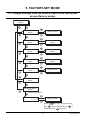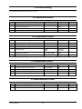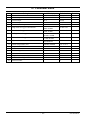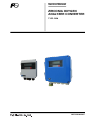
1
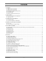
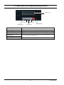
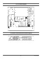
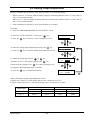
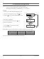
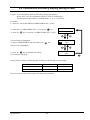
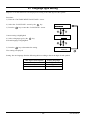
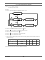
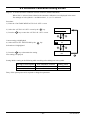
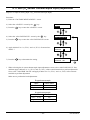
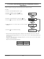
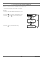
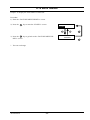
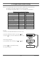
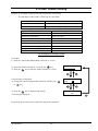
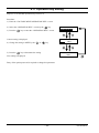
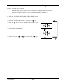
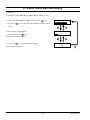
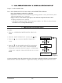
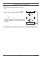
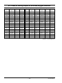
Service Manual ZIRCONIA OXYGEN ANALYZER CONVERTER TYPE: ZKM INZ-TN5A0845b-E Contents 1. GENERAL ....................................................................................................................................................1 1.1 ZKM1 Internal constitution ......................................................................................................................1 1.2 ZKM2 Internal constitution ......................................................................................................................1 1.3 Description on display/setting section ......................................................................................................2 1.4 CPU board layout .....................................................................................................................................3 1.5 I/O board layout........................................................................................................................................4 1.6 RS485 communication board layout.........................................................................................................4 2. ADJUSTMENT.............................................................................................................................................5 2.1 Necessary equipments for adjustment ......................................................................................................5 2.2 Adjustment flow........................................................................................................................................5 3. CONNECTION AND CHECK ...................................................................................................................6 3.1 Connection check......................................................................................................................................6 3.2 Connection diagram for adjustment..........................................................................................................6 4. POWER ON AND VOLTAGE CHECK.....................................................................................................7 4.1 Power ON .................................................................................................................................................7 4.2 Check of the power supply voltage...........................................................................................................7 5. FACTORY-SET MODE...............................................................................................................................8 5.1 Change settings from the initial screen to the factory-set screen (factory mode).....................................8 5.2 Initial setting .............................................................................................................................................9 5.3 Measured menu.........................................................................................................................................9 5.4 Calibration menu ......................................................................................................................................9 5.5 Blowdown menu.......................................................................................................................................9 5.6 Maintenance menu....................................................................................................................................9 5.7 Parameter menu ......................................................................................................................................10 5.8 Factory menu ..........................................................................................................................................11 6. SETTING ....................................................................................................................................................12 6.1 Analog output setting..............................................................................................................................12 6.2 Analog output adjustment .......................................................................................................................13 6.3 Blowdown setting screen ........................................................................................................................14 6.4 Combustion efficiency display setting screen.........................................................................................15 6.5 Surrounding temperature correction .......................................................................................................16 6.6 Thermocouple type setting screen ..........................................................................................................17 6.7 Language type setting .............................................................................................................................18 6.8 Communication setting ...........................................................................................................................19 6.9 Automatic calibration setting screen.......................................................................................................20 6.10 AD1 (O2 sensor input) adjustment ........................................................................................................21 6.11 AD2 (O2 sensor thermocouple input) adjustment .................................................................................22 6.12 AD3 (Thermocouple input for combustion control) adjustment...........................................................23 6.13 Entry of the option password ................................................................................................................24 6.14 Serial number........................................................................................................................................25 6.15 Digital output contact setting................................................................................................................26 6.16 RBT contact setting ..............................................................................................................................27 6.17 Operation key setting............................................................................................................................28 6.18 Wire check start time setting.................................................................................................................29 6.19 Error check start time setting ................................................................................................................30 INZ-TN5A0845-E -i- 7. CALIBRATION BY A SIMULATION INPUT....................................................................................... 31 7.1 Manual SPAN calibration ...................................................................................................................... 31 7.2 Manual ZERO calibration...................................................................................................................... 32 8. APPENDED FIGURES ............................................................................................................................. 33 8.1 Table of reference thermal electromotive force of R-type thermocouple .............................................. 33 8.2 Table of reference thermal electromotive force of K-type thermocouple .............................................. 33 8.3 Table of theory output of zirconia oxygen detector ............................................................................... 34 8.4 Key operation flow diagram .................................................................................................................. 35 - ii - INZ-TN5A0845-E 1. GENERAL 1.1 ZKM1 Internal constitution (1) CPU board (2) I/O board POWER FUSE T 0.5A (6) Tube type fuse (F1) HEATER FUSE T 2.5A PS3 CAUTION (5) Tube type fuse (F2) ON Power supply must be selected the same voltage of detector. POWER OFF (4) Power switch (3) Terminal block (7) Earth terminal TC1 AO FAULT BLOW ZV HEATER 1 2 3 4 5 6 7 8 9 10 11 12 13 14 15 16 17 18 19 20 21 22 23 24 25 26 27 28 ALARM MAINAC COM SV TC2 DI1 DI2 DI3 DIN L TENANCE COM O2 TM2 1 2 3 TXD RXD GND TRX TRX GND RS232C RS485 (7) Earth terminal 1.2 ZKM2 Internal constitution (1) CPU board (2) I/O board Oxygen Analyzer POWER FUSE T 0.5A HEATER FUSE T 2.5A ON MODE ESC ENTER POWER POWER OFF (6) Tube type fuse (F1) (5) Tube type fuse (F2) (4) Power switch 注意 変換器へ供給する電源電圧は、接続される 検出器の電源電圧に合わせてください。 CAUTION Power supply must be selected the same voltage of detector. RS232C RS485 + O2 − +TC1− + AO − 1 2 15 3 16 4 17 5 18 6 19 20 +TC2 − DI1 DI2 DI3 DI- TM2 3 2 1 GND RXD TXD GND TRX− TRX+ (3) Terminal block FAULT BLOW ZV HEATER 7 8 9 10 11 12 13 14 21 22 23 24 25 26 27 28 ALARM MAINAC COM SV N L TENANCE COM SH SH (7) Earth terminal Name (1) CPU board (2) I/O board (3) Terminal block (4) Power switch (5) Tube type fuse (F2) (6) Tube type fuse (F1) (7) Earth terminal INZ-TN5A0845-E Explanation The liquid crystal display and the memory circuit are installed. The input/output circuit and the power circuit are installed. Terminal block for various input/output signals. Turns ON/OFF this converter. (“–”: OFF, “○”: ON) Fuse for the heater. (250 V T 2.5 A) Fuse for the main unit (250 V T 0.5 A) Used as frame gland (FG). -1- 1.3 Description on display/setting section (1) Display unit (3) ESC key (2) MODE key Name (1) Display unit (2) MODE key (3) ESC key (4) Digit key (5) Up key (6) ENTER key (5) UP key (4) Digit key (6) ENTER key Explanation Displays the concentration value and setting values. Used to switch measurement display and mode display. Used to return to the previous screen or exit the setting. Used to change the setting values. Used to determine the setting values. -2- INZ-TN5A0845-E 1.4 CPU board layout INZ-TN5A0845-E -3- 1.5 I/O board layout 1.6 RS485 communication board layout -4- INZ-TN5A0845-E 2. ADJUSTMENT 2.1 Necessary equipments for adjustment Name Voltage generator Digital multi meter Specification 0 to 200 mVDC Min. resolution 0.1 mV Voltage measurement : 0 to 20 V DC Min. resolution 0.1 mV Current measurement : 0 to 100 mA DC Min. resolution 0.01 mA 2.2 Adjustment flow The ZKM adjustment flow is as follows. (1) Connection check (2) Power ON (3) Voltage check for each section (4) Factory-set mode (5) Individual adjustment (6) Calibration by a simulation input INZ-TN5A0845-E -5- No. of units 2 1 3. CONNECTION AND CHECK 3.1 Connection check Check if the connector is mounted appropriately. 3.2 Connection diagram for adjustment 1 3 1 2 3 TM2 1 CN2 CPU board (TK7N2425C1) 6 CN5 2 1 CN4 20 19 CN1 60 4 58 2 3 59 57 1 Flat cable (TK7N2425P95) 1 3 57 59 2 4 58 60 CN1 I/O board (TK7N2426C1) 1 2 3 4 5 6 + - + - + 27 28 - 0 mV 8 mV Digital Standard multi meter voltage generator AC power supply 100 to 240 VAC 50/60 Hz -6- INZ-TN5A0845-E 4. POWER ON AND VOLTAGE CHECK 4.1 Power ON Open the front flap. Turn ON (-) the power switch. OXYGEN ANALYZER VER ¾.¾¾ YY/MM WARM-UP HEATER 234 °C The message shown left appears on the LCD screen. After about 6 seconds, the display is automatically switched to the Warm-up screen. 4.2 Check of the power supply voltage Turn on the power supply of the converter and check the voltage of the printed circuit board according to the table below. Printed circuit board Check terminal CPU board Between TP2 and TP3 (TK7N2425) Between TP4 and TP5 I/O board (TK7N2426) INZ-TN5A0845-E Adjusting VR - +5.0±0.50V DC - +5.0±0.30V DC Between TP1 and TP2 - +5.0±0.30V DC Between TP3 and TP4 - +15.0±0.75V DC Between TP3 and TP10 - -15.0±0.75V DC Between TP7 and TP5 - -12.0±1.00V DC Between TP7 and TP8 - +12.0±1.00V DC -7- Adjusting voltage 5. FACTORY-SET MODE 5.1 Change settings from the initial screen to the factory-set screen (factory mode). Measurement display Measured menu screen Setting screen Calibration menu screen Performance/setting screen Blowdown menu screen Performance/setting screen *Optional function Maintenance menu screen Performance/setting screen Parameter menu screen Setting screen Factory menu screen Password setting screen Password authentication INPUT PASSWORD Setting screen ○○○○ 2404” by using the [increment] Enter “2404” key and the [digit shift] key Next, press the -8- . key once. INZ-TN5A0845-E 5.2 Initial setting The table bellows show the factory-set values. 5.3 Measured menu Item 1 2 3 4 Setting item LCD display Display range Decimal point position Full scale Calculation time of max./min. value Default value RANGE1 00.00 25.00 vol% 024 h Remarks Default value AUTO CALIBRATION NO START DATE 99/01/01 00:00 AUTO CAL. CYCLE 07d 00h 20.600% SPAN ZERO 02.000% CAL. WAIT TIME 060s ABOUT CAL. RANGE BOTH Remarks DISPLAY RANGE DECIMAL POINT FULL SCALE CALCULATE TIME 5.4 Calibration menu Item 1 2 3 4 5 6 Setting item Automatic calibration YES/NO Date and time for starting automatic calibration Automatic calibration cycle Calibration gas Calibration wait time Calibration range operation LCD display 5.5 Blowdown menu Item 1 2 3 4 Setting item Automatic blowdown YES/NO Date and time for starting automatic blowdown Automatic blowdown cycle Blowdown time LCD display BLOW DOWN START DATE AUTO BLOW CYCLE BLOW DOWN TIME Default value NO 99/01/01 00:00 24h 00m 030 s Remarks Default value NO NO Remarks 5.6 Maintenance menu Item 1 2 Setting item Sensor check for calibration Sensor recovery for calibration INZ-TN5A0845-E LCD display SENSOR CHECK SENSOR RECOVER -9- 5.7 Parameter menu Item 1 2 3 4 5 6 Setting item Current date and time Contact input Contact input Contact input Alarm contact output High limit of oxygen concentration LCD display 7 Low limit of oxygen concentration OXYGEN ALARM LOW ALARM 00.020 vol% 8 H-High limit of oxygen concentration OXYGEN ALARM H-HIGH ALARM 55.000 vol% 9 L-Low limit of oxygen concentration OXYGEN ALARM L-LOW ALARM 00.010 vol% 10 Hysteresis OXYGEN ALARM HYSTERESIS 10 % 11 12 13 14 15 16 17 18 Heater temperature error Output hold YES/NO Hold value Hold setting value Measurement wait time Key lock Automatic backlight OFF time Station number HEATER ERROR 010 °C 01 % NO 0% 000 % 010 s NO 10 m 01 DATE SET DI 1 DI 2 DI 3 DO ALARM OXYGEN ALARM HIGH ALARM OUTPUT HOLD OUTPUT SELECT HOLD VALUE MEAS. WAIT TIME KEY LOCK BACKLIGHT TIME STATION NO - 10 - Default value 00/01/01 00:00 NONE NONE NONE ALARM NONE 50.000 vol% Remarks INZ-TN5A0845-E 5.8 Factory menu Item 1 2 3 4 5 6 7 8 9 10 11 12 13 14 15 16 17 18 19 20 21 22 23 24 25 26 27 28 29 Note 1: Setting item Analog output Blowdown Combustion efficiency display Warm-up operation monitoring time Movement average time Heater temperature control Heater low temperature control Heater low temperature control time Heater temperature error Thermocouple type Language type Password Manual sensor recovery type AC recovery High temperature recovery PID parameter Default parameter Communication Automatic calibration Error check start time Operation key Error output RBT contact Surrounding temperature Offset at 10°C Output contact Wire check start time Option password Main unit serial number LCD display Default value ANALOG OUT TYPE 4 to 20 mA BLOW DOWN NO COMBUSTIBLE TIME NO WARM-UP TIME 45 m AVERAGING TIME 02 s TEMP. CONTROL 800 °C LOW TEMP. 70 °C LOW TEMP. TIME 30 m HEATER TEMP.ERR. 70 °C 1% THERMO COUPLE R-TYPE LANGUAGE ENGLISH PASSWORD 2404 RECOVER TYPE AC Ω TIME 100 Ω 005 m HI-TEMP. TIME 900 °C 010 m P I D 020 03000 00600 DEFAULT PARA SET YES COMMUNICATION RS232C AUTO CAL. SET NO ERR CHECK TIME 420 s OPERATION KEY 5 KEY ERROR OUT YES RBT CONTACT NO SURROUNDING TEMP ZERO COUNT OFFSET 10°C 378 DIGITAL OUT SET NO WIRE CHECK TIME 05 m OPTION PASS ID INFO - Entry of the option password is required to change settings. INZ-TN5A0845-E - 11 - Remarks <Note 1> <Note 1> <Note 1> <Note 1> <Note 1> <Note 1> 6. SETTING 6.1 Analog output setting Purpose: To set an analog output type (4 to 20 mA/0 to 1 V). Procedure: 1) Enter the <FACTORY MENU/ANALOG OUT TYPE> screen. 2) Select the <ANALOG OUT TYPE> screen by the 3) Press the key. key to enter the <ANALOG OUT TYPE> screen. Current setting is highlighted. 4) Select an analog output type by the FACTORY MENU ANALOG OUT TYPE ANALOG OUT TYPE 4-20mA 0-1V key. Selected type is highlighted. 5) Press the key to determine the setting. ANALOG OUT TYPE 4-20mA The set type is displayed. * Always switch the output jumper pin (JP6) on the CPU printed circuit board after selection of the output. 5th digit of code symbol B E Output type 4 to 20 mA 0 to 1 V - 12 - JP6 1 to 2 2 to 3 INZ-TN5A0845-E 6.2 Analog output adjustment Purpose: To adjust "0% (4 mA/0V)” and “100% (20 mA/1V)” of an analog output. * When "4-20 mA” is selected, adjust an analog output by connecting ammeter to the "5 (+AO)” and “6 (AO)” of an external terminals. When “0-1V" is selected, adjust an analog output by connecting the voltmeter to the "5 (+AO)” and “6 (AO)” of an external terminals. * Same adjustment for the factory mode. (both of them are available) Procedure: 1) Enter the <PARAMETER MENU/A-OUT ADJUST> screen. key. 2) Select the <A-OUT ADJUST> screen by the 3) Press the key to enter the <A-OUT ADJUST> screen. key. 4) Select the analog output adjustment screen by the 5) Press the PARAMETER MENU key to enter the analog output adjustment screen. 6) Adjust an analog output by the or key. "DOWN" or “UP” is selectable by pressing the Change an analog output by the A-OUT ADJUST A-OUT ADJUST ANALOG OUT 0% ANALOG 00005545 key. 0% DOWN key while checking the ana- log output by the digital multi meter or the like. 7) Press the key to determine the setting. ANALOG 00005545 0% DOWN When selecting the analog output adjustment screen ; If adjust “0% (4 mA/0V)” of the analog output, select “ANALOG OUT 0%”. If adjust “100% (20 mA/1V)” of the analog output, select “ANALOG OUT 100%”. Output type 4 to 20 mA 0 to 1 V INZ-TN5A0845-E Output 0% 4.00 mA 0.00 V 100 % 20.00 mA 1.00 V - 13 - Count value 0% 100 % 5550 28070 9600 29600 6.3 Blowdown setting screen Purpose: To set the blowdown function YES/NO (Enabled /Disabled). If “NO” is set, items for blowdown are not displayed in the menu. The 9th digit of code symbol is <enabled when 2, 4, 6, or 7 is selected> Procedure: 1) Enter the <FACTORY MENU/BLOW DOWN> screen. key. 2) Select the <BLOW DOWN> screen by the 3) Press the key to enter the <BLOW DOWN> screen. Current setting is highlighted. FACTORY MENU BLOW DOWN BLOW DOWN key. 4) Select BLOWDOWN YES/NO by the YES NO Selected one is highlighted. 5) Press the key to determine the setting. BLOW DOWN YES Your setting is displayed. Setting: Make a setting as the following table according to the 9th digit of the code symbol. 9th digit of code symbol Y, 1, 3, 5 2, 4, 6, 7 Blowdown function Disabled Enabled Setting value NO YES Entry of the option password is required to change this parameter. - 14 - INZ-TN5A0845-E 6.4 Combustion efficiency display setting screen Purpose: To set combustion efficiency YES/NO (Display/Not display). When “NO” is set, the combustion efficiency screen is not displayed. The 9th digit of code symbol is <enabled when 1, 4, 5, or 7 is selected>. Procedure: 1) Enter the <FACTORY MENU/COMBUSTIBLE EFF.> screen. key. 2) Select the <COMBUSTIBLE EFF.> screen by the 3) Press the key to enter the <COMBUSTIBLE EFF.> screen. Current setting is highlighted. 4) Select COMBUNTIBLE EFF. YES/NO by the FACTORY MENU COMBUSTIBLE EFF. COMBUSTIBLE EFF. key. YES NO Selected one is highlighted. 5) Press the key to determine the setting. COMBUSTIBLE EFF. YES Your setting is displayed. Setting: Make a setting as following table according to the 9th digit of code symbol. 9th digit of code symbol Y, 2, 3, 6 1, 4, 5, 7 Screen display Not displayed Displayed Entry of the option password is required to change this parameter. INZ-TN5A0845-E - 15 - Setting value NO YES 6.5 Surrounding temperature correction Purpose: To adjust an analog input 2 (O2 sensor thermocouple input). Procedure: 1) Enter the <FACTORY MENU/SURROUNDING TEMP> screen. 2) Select the <SURROUNDING TEMP> screen by the 3) Press the key. key to enter the <SURROUNDING TEMP> FACTORY MENU SURROUNDING TEMP screen. 4) Select “ZERO COUNT” by the key. SURROUNDING TEMP ZERO COUNT 5) Set the surrounding temperature near the converter by the or ZERO COUNT 14552 029°C key. 3500 Input a count value (1, 2500, or 5000). 1 : 34°C 2500 : 25°C 5000 : 20°C 6) Press the key to determine the setting. ZERO COUNT 14552 029°C - 16 - 3500 INZ-TN5A0845-E 6.6 Thermocouple type setting screen Purpose: To set a thermocouple type for temperature measurement of the detector. The 4th digit of code symbol <K: when K thermocouple is specified> Procedure: Select the <THERMO COUPLE> screen by the Press the key. key to enter the <THERMO COUPLE> screen. Current setting is highlighted. Select a THERMO COUPLE K-TYPE/R-TYPE by the Selected one is highlighted. key to determine the setting. Press the Your setting is displayed. THERMO COUPLE THERMO COUPLE key. K-TYPE R-TYPE THERMO COUPLE K-TYPE * R-type thermocouple : I/O board TK7N2426C1 R-thermo K-type thermocouple : I/O board TK7N2426C2 K-thermo Circuit constants are different. INZ-TN5A0845-E FACTORY MENU - 17 - 6.7 Language type setting Purpose: To set the characters to be displayed according to the 10th digit of code symbol. Procedure: 1) Enter the <FACTORY MENU/LANGUAGE> screen. 2) Select the <LANGUAGE> screen by the 3) Press the key. key to enter the <LANGUAGE> screen. Current setting is highlighted. 4) Select a language type by the FACTORY MENU LANGUAGE LANGUAGE ENGLISH key. Selected language is highlighted. 5) Press the key to determine the setting. LANGUAGE ENGLISH Your setting is displayed. Setting: Set one language from the following table according to the 10 the digit of code symbol. 10th digit of code symbol J E C - 18 - Display language Japanese English Chinese INZ-TN5A0845-E 6.8 Communication setting Purpose: To set a communication type. The 6th digit of code symbol Procedure: 1) Enter the <FACTORY MENU/COMMUNICATION> screen. FACTORY MENU COMMUNICATION COMMUNICATION COMMUNICATION RS232C RS232C COMMUNICATION COMMUNICATION RS485 RS485 2) Select the <COMMUNICATION> screen by the 3) Press the key. key to enter the <COMMUNICATION> screen. 4) Select a communication type by the key. 5) Press the key to determine the communication type. 6) Press the key to determine the setting. * Always switch the output jumper pin (JP1, JP2) on the CPU printed circuit board after selection of a communication type. 6th digit of code symbol Communication type 1 RS232C 2 RS485 JP1 3-5 4-6 1-3 2-4 Entry of the option password is required to change this parameter. INZ-TN5A0845-E - 19 - JP2 3-5 4-6 1-3 2-4 JP5 JP6 2-3 - 1-2 - 6.9 Automatic calibration setting screen Purpose: To set the automatic calibration function YES/NO (Enabled/Disabled). When “NO" is selected, items related to the automatic calibration is not displayed in the menu. The 9th digit of code symbol is <available when 3, 5, 6, or 7 is selected> Procedure: 1) Enter the <FACTORY MENU/AUTO CAL. SET> screen. key. 2) Select the <AUTO CAL. SET> screen by the 3) Press the key to enter the <AUTO CAL. SET> screen. Current setting is highlighted. FACTORY MENU AUTO CAL. SET AUTO CAL. SET 4) Select AUTO CAL. SET YES/NO by the key. YES NO Selected one is highlighted. 5) Press the key to determine the setting. AUTO CAL. SET YES Your setting is displayed. Setting: Make a setting as the following table according to the 9th digit of code symbol. 9th digit of code symbol Y, 1, 2, 4 3, 5, 6, 7 Auto calibration function Disabled Enabled Setting value NO YES Entry of the option password is required to change this parameter. - 20 - INZ-TN5A0845-E 6.10 AD1 (O2 sensor input) adjustment Purpose: To adjust an analog input 1 (O2 sensor input). Procedure: 1) Enter the <FACTORY MENU/ADJUDT> screen. 2) Select the <ADJUST> screen by the 3) Press the key. FACTORY MENU key. 4) Select the <AD1 LOW VALUE> screen by the 5) Press the ADJUST key to enter the <ADJUST> screen. key to enter the <AD1 LOW VALUE> screen. ADJUST AD1 LOW VALUE 6) Apply 0.000 mV to "1 (+O2)” and “2 (-O2)” of the external terminals. * AD1 LOW VALUE key to determine the setting. AD1 LOW VALUE 7) Press the 00007865 SET 00007865 SET * When selecting the O2 sensor input adjustment screen, select “AD1 LOW VALUE” first, and then apply 0.000 mV to "1 (+O2)” and “2 (-O2)” of the external terminals to perform adjustment. Next, select “AD1 HIGH VALUE” and apply 100.000 mV to "1 (+O2)” and “2 (-O2)” of the external terminals to perform adjustment. Make sure to perform the both adjustments. Input Low : 0 mV High : 100 mV INZ-TN5A0845-E Count value 7800 17200 - 21 - 6.11 AD2 (O2 sensor thermocouple input) adjustment Purpose: To adjust an analog input 2 (O2 sensor thermocouple input). Procedure: 1) Enter the <FACTORY MENU/ADJUST> screen. 2) Select the <ADJUST> screen by the 3) Press the key. FACTORY MENU key. 4) Select the <AD2 LOW VALUE> screen by the 5) Press the ADJUST key to enter the <ADJUST> screen. key to enter the <AD2 LOW VALUE>screen. ADJUST AD2 LOW VALUE 6) Apply 0,000 mV to “3 (+TC1)” and “4 (-TC1)” of external terminals. * AD2 LOW VALUE key to determine the setting. AD2 LOW VALUE 7) Press the 00000700 SET 00000700 SET * When selecting the O2 sensor thermocouple input adjustment screen, select “AD2 LOW VALUE” first, and then apply 0.000 mV to "3 (+TC1)” and “4 (-TC1)” of the external terminals to perform adjustment. Next, select “AD2 HIGH VALUE” and apply 9.000 mV to "3 (+TC1)” and “4 (-TC2)” of the external terminals to perform adjustment. Make sure to perform the both adjustments. R-type thermocouple Input Low : 0 mV High : 9 mV Count value 1000 29600 K-type thermocouple Input Low : 0 mV High : 40 mV Count value 700 32700 - 22 - INZ-TN5A0845-E 6.12 AD3 (Thermocouple input for combustion control) adjustment Purpose: To adjust an analog input 3 (thermocouple input for combustion control). Procedure: 1) Enter the <FACTORY MENU/ADJUST> screen. 2) Select the <ADJUST> screen by the 3) Press the key. FACTORY MENU key. 4) Select the <AD3 LOW VALUE> screen by the 5) Press the ADJUST key to enter the <ADJUST> screen. key to enter the <AD3 LOW VALUE> screen. 6) Apply 0.000 mV to "15 (+TC2)” and “16 (-TC2)” of external terminals. * 7) Press the key to determine the setting. ADJUST AD3 LOW VALUE AD3 LOW VALUE 00000080 SET AD3 LOW VALUE 00000080 SET * When selecting the thermocouple input for combustion control adjustment screen, select “AD3 LOW VALUE” first, and then apply 0.000 mV to "15 (+TC2)” and “16 (-TC2)” of the external terminals to perform adjustment. Next, select “AD3 HIGH VALUE” and apply 9.000 mV to "15 (+TC2)” and “16 (-TC2)” of the external terminals to perform adjustment. Make sure to perform the both adjustments. Input Low : 0 mV High : 9 mV INZ-TN5A0845-E Count value 1200 15800 - 23 - 6.13 Entry of the option password Purpose: To enter the password for changing settings of option items. * Password is managed by each unit and it is not public. Procedure: 1) Enter the <FACTORY MENU/OPTION PASS> screen. 2) Press the key to enter the <PASSWORD> screen. 3) Press the and keys to enter the password. FACTORY MENU OPTION PASS OPTION PASS 00000000 4) Press the key to determine the setting. OPTION PASS 00000000 - 24 - INZ-TN5A0845-E 6.14 Serial number Purpose: To display the serial number of main unit. Procedure: 1) Enter the <FACTORY MENU/ID INFO> screen. 2) Press the key to enter the <ID INFO> screen. FACTORY MENU ID INFO 3) Press the key to go back to the <FACTORY MENU/ID A0A0000T INFO> screen. * You can not change. INZ-TN5A0845-E SERIAL No. - 25 - 6.15 Digital output contact setting Purpose: To set a digital output contact for COSA, DELTA, and RBT. [Free terminal allocation] The 4th digit of code symbol <When R or K is specified: for RTB> The 12th digit of code symbol <When 3, 4, 6, or 7 is specified: for COSA/DELTA> Differences from the standard specification Function Standard spec. COSA/DELTA spec. Maintenance(MAINTE) DO6 (fixed) DO1 to DO6 (settable) Calibration (MAINTE) DO6 (fixed) DO1 to DO6 (settable) Blowdown (BLOW) DO5 (fixed) DO1 to DO6 (settable) Span valve (SV) DO4 (fixed) DO1 to DO6 (settable) Zero valve (ZV) DO3 (fixed) DO1 to DO6 (settable) H alarm (ALARM) DO2 (fixed) DO1 to DO6 (settable) L alarm (ALARM) DO2 (fixed) DO1 to DO6 (settable) H-High alarm (ALARM) DO2 (fixed) DO1 to DO6 (settable) L-Low alarm (ALARM) DO2 (fixed) DO1 to DO6 (settable) Equipment failure (FAULT) DO1 (fixed) DO1 to DO6 (settable) Calibration error (ALARM) DO1 (fixed) DO1 to DO6 (settable) Rich mode DO1 to DO6 (settable) Reserved DO1 to DO6 (settable) * For ALARM, “Enable” should be set to an alarm output. Procedure: 1) Enter the <FACTORY MENU/DIGITAL OUT SET> screen. 2) Select the <DIGITAL OUT SET> screen by the 3) Press the key. key to enter the <DIGITAL OUT SET> screen. Current setting is displayed. 4) Select DIGITAL OUT SET YES by the 5) Press the FACTORY MENU DIGITAL OUT SET DIGITAL OUT SET or key. key to determine the setting. YES NO DIGITAL OUT SET YES Your setting is displayed. - 26 - INZ-TN5A0845-E 6.16 RBT contact setting Purpose: To set a RBT contact specification [Normally closed (NC)]. The 4th digit of code symbol <when R or K is specified> 4th digit of code symbol R K Case structure RB spec. of bench type R-type thermocouple RB spec. of bench type K-type thermocouple Target for NC Maintenance (MAINTE) Calibration (MAINTE) H alarm (ALARM) L alarm (ALARM) H-High alarm (ALARM) L-Low alarm (ALARM) Equipment failure (FAULT) Calibration error (ALARM) Not target for NC Blowdown (BLOW) Span valve (SV) Zero valve (ZV) Rich mode List of targets for normally closed Procedure: 1) Enter the <FACTORY MENU/RBT CONTACT> screen. 2) Select the <RBT CONTACT> screen by the 3) Press the key. key to enter the <RBT CONTACT> screen. FACTORY MENU RBT CONTACT Current setting is displayed. RBT CONTACT 4) Change the current setting to RBT CONTACT YES by the YES or NO key. 5) Press the key to determine the setting. RBT CONTACT YES Your setting is displayed. Entry of the option password is required to change this parameter. INZ-TN5A0845-E - 27 - 6.17 Operation key setting Purpose: To set the RBT operation key from 5 to 4. Procedure: 1) Enter the <FACTORY MENU/OPERATION KEY> screen. 2) Select the <OPERATION KEY> screen by the 3) Press the key. key to enter the <OPERATION KEY> screen. Current setting is displayed. 4) Change the setting to 4KEY by the 5) Press the FACTORY MENU OPERATION KEY OPERATION KEY or key. key to determine the setting. 5KEY 4KEY OPERATION KEY 4KEY Your setting is displayed. Entry of the option password is required to change this parameter. - 28 - INZ-TN5A0845-E 6.18 Wire check start time setting Purpose: To set the wire check time. When the input signal is beyond 1150 mV, the alarm is output after the wire check time. (Input signal may be 1150 mV or more at combustion initiation of furnace.) Procedure: 1) Enter the <FACTORY MENU/WIRE CHECK TIME> screen. 2) Select the <WIRE CHECK TIME> screen by the 3) Press the key. key to enter the <WIRE CHECK TIME> screen. 4) Current setting is highlighted. FACTORY MENU WIRE CHECK TIME WIRE CHECK TIME 05 m 5) Set the time by the or key and press the WIRE CHECK TIME 05 m determine. INZ-TN5A0845-E key to - 29 - 6.19 Error check start time setting Procedure: 1) Enter the <FACTORY MENU/ERR CHECK TIME> screen. 2) Select the <ERR CHECK TIME> screen by the 3) Press the key. key to enter the <ERR CHECK TIME> setting FACTORY MENU ERR CHECK TIME screen. Current setting is highlighted. 4) Select time by the ERR CHECK TIME 420s key. Selected time is highlighted. 5) Press the key to determine the setting. ERR CHECK TIME 420s Your setting is displayed. - 30 - INZ-TN5A0845-E 7. CALIBRATION BY A SIMULATION INPUT Purpose: To calibrate SPAN/ZERO. Note: • After adjustment of AD1 (O2 sensor input), perform SPAN/ZERO calibration. • After Span calibration, perform Zero calibration. • SPAN/ZERO calibration are not available during warm-up operation or error (disconnection, abnormal heater temperature, etc.) occurrence. • Apply to AD2 (O2 sensor thermocouple input) so that the heater temperature becomes 800°C. The heater temperature to be displayed = AD2 (Heater temperature input) + Room temperature. (Refer to “8.1 Table of reference thermal electromotive force of R-type thermocouple”) 7.1 Manual SPAN calibration Procedure: 1) Enter the <CALIBRATION MENU/MANUAL SPAN CAL.> screen. 2) Select the <MANUAL SPAN CAL.> screen by the 3) Press the key. key to enter the <MANUAL SPAN CAL.> CALIBRATION MENU MANUAL SPAN CAL. screen. 4) Press the key after applied 0.000 mV DC (equivalent of 20.6 vol%) to "1 (+O2)” and “2 (-O2)” of external terminals. * If SPAN gas concentration has been changed at “Calibration gas setting screen”, apply the voltage which falls into the set concentration. MANUAL SPAN CAL. START MANUAL SPAN CAL. 20.61 % 00.01 mV Calibration is completed Oxygen concentration value and electromotive force of O2 sensor are displayed during execution of manual SPAN calibration. When the calibration is completed successfully, the display transits to the menu screen. INZ-TN5A0845-E - 31 - 7.2 Manual ZERO calibration Procedure: 1) Enter the <CALIBRATION MENU/MANUAL ZERO CAL.> screen. 2) Select the <MANUAL ZERO CAL.> screen by the 3) Press the key. key to enter the <MANUAL ZERO CAL.> CALIBRATION MENU MANUAL ZERO CAL. screen. 4) Press the key while applying 51.39 mV DC (2.0 vol%) to "1 (+O2)” and “2 (-O2)” of external terminals. * If ZERO gas concentration has been changed at “Calibration gas setting screen”, after applied the voltage which falls into the set concentration. MANUAL ZERO CAL. START MANUAL ZERO CAL. 02.01 % 51.39 mV Calibration is completed Oxygen concentration value and electromotive force of O2 sensor are displayed during execution of manual ZERO calibration. When the calibration is completed successfully, the display transits to the menu screen. - 32 - INZ-TN5A0845-E 8. APPENDED FIGURES 8.1 Table of reference thermal electromotive force of R-type thermocouple Unit : mV Temperature (°C) 0 10 20 30 40 50 60 70 80 90 100 JIS C 1602-1995 0 100 200 300 400 500 600 700 800 900 0.000 0.054 0.111 0.171 0.232 0.296 0.363 0.431 0.501 0.573 0.647 0.647 0.723 0.800 0.879 0.959 1.041 1.124 1.208 1.294 1.381 1.469 1.469 1.558 1.648 1.738 1.831 1.923 2,.017 2.112 2.207 2.304 2.401 2.401 2.498 2.597 2.696 2.796 2.896 2.997 3.099 3.201 3.304 3.408 3.408 3.512 3.616 3.721 3.827 3.933 4.040 4.147 4.255 4.363 4.471 4.471 4.580 4.690 4.800 4.910 5.021 5.133 5.245 5.357 5.470 5.583 5.583 5.697 5.812 5.926 6.041 6.157 6.273 6.390 6.507 6.625 6.743 6.743 6.861 6.980 7.100 7.220 7.340 7.461 7.583 7.705 7.827 7.950 7.950 8.073 8.197 8.321 8.446 8.571 8.697 8.823 8.950 9.077 9.205 9.205 9.333 9.461 9.590 9.720 9.850 9.980 10.111 10.242 10.374 10.506 8.2 Table of reference thermal electromotive force of K-type thermocouple Unit : mV Temperature (°C) 0 10 20 30 40 50 60 70 80 90 100 INZ-TN5A0845-E JIS C 1602-1995 0 100 200 300 400 500 600 700 800 900 0 0.397 0.798 1.203 1.612 2.023 2.436 2.851 3.267 3.682 4.096 4.096 4.509 4.920 5.328 5.735 6.138 6.540 6.941 7.340 7.739 8.138 8.138 8.539 8.940 9.343 9.747 10.153 10.561 10.971 11.382 11.795 12.209 12.209 12.624 13.040 13.457 13.874 14.293 14.713 15.133 15.554 15.975 16.397 16.397 16.820 17.243 17.667 18.091 18.516 18.941 19.366 19.792 20.218 20.644 20.644 21.071 21.497 21.924 22.350 22.776 23.203 23.629 24.055 24.480 24.905 24.905 25.330 25.755 26.179 26.602 27.025 27.447 27.869 28.289 28.710 29.129 29.129 29.548 29.965 30.382 30.798 31.213 31.628 32.041 32.453 32.865 33.275 33.275 33.685 34.093 34.501 34.908 35.313 35.718 36.121 36.524 36.925 37.326 37.326 37.725 38.124 38.522 38.918 39.314 39.708 40.101 40.494 40.885 41.276 - 33 - 8.3 Table of theory output of zirconia oxygen detector O2 conc. % 0.01 0.02 0.03 0.04 0.05 0.06 0.07 0.08 0.09 0.1 0.2 0.3 0.4 0.5 0.6 0.7 0.8 Output mV 168.15 152.87 143.94 137.6 132.68 128.66 125.27 122.32 119.73 117.41 102.13 93.20 86.86 81.94 77.92 74.53 71.58 O2 conc. % 0.9 1.0 1.2 1.4 1.5 1.6 1.8 2.0 2.2 2.4 2.6 2.8 3.0 3.5 4.0 4.5 5.0 Output mV 68.99 66.67 62.65 59.25 57.73 56.31 53.71 51.39 49.29 47.37 45.61 43.98 42.46 39.06 36.12 33.52 31.20 O2 conc. % 5.5 6.0 6.5 7.0 7.5 8.0 9.0 10.0 11.0 12 13 14 15 16 17 18 19 Output mV 29.10 27.18 25.42 23.79 22.27 20.84 18.25 15.93 13.83 11.91 10.14 8.511 6.991 5.569 4.233 2.973 1.782 O2 Output O2 conc. % mV conc. % 20 0.651 36 20.6 0.000 37 21 -0.4238 38 22 -1.449 39 23 -2.428 40 24 -3.366 41 25 -4.266 42 26 -5.130 43 27 -5.962 44 28 -6.763 45 29 -7.537 46 30 -8.284 47 31 -9.01 48 32 -9.71 49 33 -10.38 50 34 -11.04 35 -11.68 Output mV -12.30 -12.91 -13.49 -14.06 -14.62 -15.17 -15.70 -16.22 -16.72 -17.22 -17.70 -18.18 -18.64 -19.10 -19.54 E (mV) = 50.74 log20.6/x - 34 - INZ-TN5A0845-E 8.4 Key operation flow diagram (17(5 key (6& 32:(521 2;<*(1$1$/<=(5 9(5 key 02'( key ڸ key Automatic transition Displayed only during warming-up. 0($685(0(18 &$/,%5$7,210(18 :$5083 +($7(5Υ YRO 0($685(0(18 ',63/$<5$1*( ',63/$<5$1*( 5$1*(5$1*( ',63/$<5$1*( 5$1*( 0($685(0(18 2873875$1*( 2873875$1*( '(&,0$/32,17 '(&,0$/32,17 '(&,0$/32,17 2873875$1*( )8//6&$/( )8//6&$/( )8//6&$/( 2873875$1*( '(&,0$/32,17 '(&,0$/32,17 '(&,0$/32,17 2873875$1*( )8//6&$/( )8//6&$/( )8//6&$/( &$/&8/$7(7,0( K &$/&8/$7(7,0( K 0$;YRO 0,1YRO &(//P9 7(03Υ 0($685(0(18 2873875$1*( &20%867,21 Displayed only if the optional function is used. *$67(03 ࠉΥ 0($685(0(18 &$/&8/$7(7,0( Displayed only if the optional function is used. Displayed only if the optional function is used. &$/,%5$7,210(18 %/2:'2:10(18 a INZ-TN5A0845-E b &$/,%5$7,210(18 6(7$872&$/ 6(7$872&$/ $872&$/,%5$7,21 $872&$/,%5$7,21 <(612 $872&$/,%5$7,21 <(6 6(7$872&$/ 67$57'$7( 67$57'$7( 67$57'$7( 6(7$872&$/ $872&$/&<&/( $872&$/&<&/( GK $872&$/&<&/( GK &$/,%5$7,210(18 $//&$/,%5$7,21 $//&$/,%5$7,21 67$57 $//&$/,%5$7,21 P9 &$/,%5$7,210(18 0$18$/63$1&$/ 0$18$/63$1&$/ 67$57 0$18$/63$1&$/ P9 0$18$/63$1&$/ P9 &$/,%5$7,210(18 0$18$/=(52&$/ 0$18$/=(52&$/ 67$57 0$18$/=(52&$/ P9 0$18$/=(52&$/ P9 &$/,%5$7,210(18 &$/*$65$1*( 63$1=(52 63$1=(52 &$/,%5$7,210(18 &$/*$65$1*( 63$1=(52 63$1=(52 &$/,%5$7,210(18 &$/:$,77,0( &$/:$,77,0( V &$/:$,77,0( V &$/,%5$7,210(18 &$/(5525&/($5 &$/(5525&/($5 <(6 &$/(5525&/($5 <(6" &$/,%5$7,210(18 $%287&$/5$1*( $%287&$/5$1*( %27+&855(17 $%287&$/5$1*( %27+ c - 35 - Displayed only if the optional function is used. a b c Displayed only if the optional function is used. %/2:'2:10(18 0$,17(0(18 0$,17(0(18 3$5$0(7(50(18 %/2:'2:10(18 6(7$872%/2: 6(7$872%/2: $872%/2: %/2:'2:1 <(612 %/2:'2:1 <(6 6(7$872%/2: 67$57'$7( 67$57'$7( 67$57'$7( 6(7$872%/2: $872%/2:&<&/( $872%/2:&<&/( KP $872%/2:&<&/( KP 6(7$872%/2: %/2:'2:17,0( %/2:'2:17,0( V %/2:'2:17,0( V %/2:'2:10(18 0$18$/%/2:'2:1 0$18$/%/2:'2:1 67$57 0$18$/%/2:'2:1 YRO 0$,17(0(18 (5525/2* (5525/2* ',63&/($5 <<00''++00 &/($5(5525/2* <(6 0$,17(0(18 $/$50/2* $/$50/2* ',63&/($5 <<00''++00 &/($5$/$50/2* <(6 0$,17(0(18 23(5$7,21/2* 23(5$7,21/2* ',63&/($5 &/($5(5525/2* <(6" &/($5$/$50/2* <(6" <<00''++00 &/($523(5$7,21/2* <(6 &/($523(5$7,21/2* <(6" Displayed only if the optional function is used. 0$,17(0(18 &$/&(//0$,17( a b &$/&(//0$,17( 6(1625&+(&." 6(1625&+(&. <(612 6(1625&+(&. <(6 &$/&(//0$,17( 6(16255(&29(5 6(16255(&29(5 <(612 6(16255(&29(5 <(6 0$,17(0(18 6(1625&+(&. 6(1625&+(&. 67$57 6(1625&+(&. P9 6(1625&+(&. Ȑ 0$,17(0(18 6(16255(&29(5 6(16255(&29(5 67$57 6(16255(&29(5 P9 6(16255(&29(5 $& 0$,17(0(18 &(//5(6,6725 &(//5(6,6725 Ȑ 0$,17(0(18 0$,17(1$1&(02'( 0$,17(1$1&(02'( <(612 0$,17(1$1&(02'( <(6 0$,17(0(18 3$66:25' 1(:3$66:25' 2/'3$66:25' 0$,17(0(18 3,'$872781,1* 3,'$872781,1* 67$57 3,'$872781,1* Υ 1(:3$66:25' c - 36 - INZ-TN5A0845-E a b c 3$5$0(7(50(18 )$&725<0(18 3$5$0(7(50(18 '$7(6(7 '$7(6(7 '$7(6(7 3$5$0(7(50(18 ',*,7$/,1387 ',*,7$/,1387 ', ', 121( ', 121( ',*,7$/,1387 ', ', 121( ', 121( ',*,7$/,1387 ', ', 121( ', 121( 3$5$0(7(50(18 '2$/$506(7 '2$/$506(7 +,*+$/$50 '2$/$506(7 +,*+$/$50 3$5$0(7(50(18 2;<*(1$/$50 2;<*(1$/$50 +,*+$/$50 +,*+$/$50 YRO +,*+$/$50 YRO 2;<*(1$/$50 /2:$/$50 /2:$/$50 YRO /2:$/$50 YRO 2;<*(1$/$50 ++,*+$/$50 ++,*+$/$50 YRO ++,*+$/$50 YRO 2;<*(1$/$50 //2:$/$50 //2:$/$50 YRO //2:$/$50 YRO 2;<*(1$/$50 +<67(5(6,6 +<67(5(6,6 +<67(5(6,6 2;<*(1$/$50 +,*+$/$50 +,*+$/$50 YRO +,*+$/$50 YRO 2;<*(1$/$50 /2:$/$50 /2:$/$50 YRO /2:$/$50 YRO 2;<*(1$/$50 ++,*+$/$50 ++,*+$/$50 YRO ++,*+$/$50 YRO 2;<*(1$/$50 //2:$/$50 //2:$/$50 YRO //2:$/$50 YRO 2;<*(1$/$50 +<67(5(6,6 +<67(5(6,6 +<67(5(6,6 $2+2/'0$,17( 287387+2/' 287387+2/' <(612 287387+2/' <(6 $2+2/'0$,17( 2873876(/(&7 2873876(/(&7 2873876(/(&7 $2+2/'0$,17( +2/'9$/8( +2/'9$/8( +2/'9$/8( $2+2/'0$,17( 0($6:$,77,0( 0($6:$,77,0( V 0($6:$,77,0( V 3$5$0(7(50(18 2;<*(1$/$50 3$5$0(7(50(18 $2+2/'0$,17( a INZ-TN5A0845-E b c d e f - 37 - a b c d e f 2#4#/'6'4/'07 #1*1.& '4414 #1*1.& '4414 176276*1.& 176276*1.& ;'501 176276*1.& ;'5 #1*1.& '4414 1762765'.'%6 1762765'.'%6 1762765'.'%6 #1*1.& '4414 *1.&8#.7' *1.&8#.7' *1.&8#.7' 2#4#/'6'4/'07 -';.1%- -';.1%;'501 +02762#55914& -';.1%;'5 2#4#/'6'4/'07 %1064#56 %1064#56 &190 %1064#56 &190 2#4#/'6'4/'07 $#%-.+)*66+/' $#%-.+)*66+/' O $#%-.+)*66+/' O 2#4#/'6'4/'07 56#6+1001 56#6+1001 56#6+1001 2#4#/'6'4/'07 #176#&,756 #176#&,756 #0#.1)176 #&,756 &190 #&,756 &190 #176#&,756 #0#.1)176 #&,756 &190 #&,756 &190 Displayed only if the optional function is used. a b 2#4#/'6'4/'07 (7'.%1'(( (7'.%1'(( (7'.%1'(( 2#4#/'6'4/'07 &+)+6#.176276 &+)+6#.176276 (#7.6 (#7.6 &1 (#7.6 &1 &+)+6#.176276 %#.+$'4414 %#.+$'4414 &1 %#.+$'4414 &1 &+)+6#.176276 **#.#4/ **#.#4/ &1 **#.#4/ &1 &+)+6#.176276 ..#.#4/ ..#.#4/ &1 ..#.#4/ &1 &+)+6#.176276 *#.#4/ *#.#4/ &1 *#.#4/ &1 &+)+6#.176276 .#.#4/ .#.#4/ &1 .#.#4/ &1 &+)+6#.176276 /#+06' /#+06' &1 /#+06' &1 &+)+6#.176276 %#.+$4#6+10 %#.+$4#6+10 &1 %#.+$4#6+10 &1 &+)+6#.176276 4+%*/1&' 4+%*/1&' &1 4+%*/1&' &1 #176#&,756 $.19 $.19 &1 $.19 &1 #176#&,756 58 58 &1 58 &1 #176#&,756 <8 <8 &1 <8 &1 c - 38 - INZ-TN5A0845-E a b c (#%614;/'07 /'#574'/'07 +02762#55914& a INZ-TN5A0845-E b (#%614;/'07 #0#.1)1766;2' #0#.1)1766;2' O#8 #0#.1)1766;2' O# (#%614;/'07 $.19&190 $.19&190 ;'501 $.19&190 ;'5 (#%614;/'07 %1/$756+$.''(( %1/$756+$.''(( ;'501 %1/$756+$.''(( ;'5 (#%614;/'07 9#4/726+/' 9#4/726+/' O 9#4/726+/' O (#%614;/'07 #8'4#)+0)6+/' #8'4#)+0)6+/' U #8'4#)+0)6+/' U (#%614;/'07 5'66'/2%10641. 5'66'/2%10641. 6'/2%10641. 6'/2%10641. ͠ 6'/2%10641. ͠ 5'66'/2%10641. .196'/2 .196'/2 ͠ .196'/2 ͠ 5'66'/2%10641. .196'/26+/' .196'/26+/' O .196'/26+/' O (#%614;/'07 *'#6'4'4414 *'#6'4'4414 ͠ *'#6'4'4414 ͠ (#%614;/'07 6*'4/1%172.' 6*'4/1%172.' -6;2'46;2' 6*'4/1%172' 46;2' (#%614;/'07 .#0)7#)' .#0)7#)' '0).+5* .#0)7#)' '0).+5* (#%614;/'07 2#55914& 2#55914& 2#55914& (#%614;/'07 #&,756 #&,756 #0#.1)176 #&,756 &190 #&,756 &190 #&,756 #0#.1)#76 #&,756 &190 #&,756 &190 #&,756 #&.198#.7' #&.198#.7' 5'6 #&.198#.7' 5'6 #&,756 #&*+)*8#.7' #&*+)*8#.7' 5'6 #&*+)*8#.7' 5'6 #&,756 #&.198#.7' #&.198#.7' 5'6 #&.198#.7' 5'6 #&,756 #&*+)*8#.7' #&*+)*8#.7' 5'6 #&*+)*8#.7' 5'6 #&,756 #&.198#.7' #&.198#.7' 5'6 #&.198#.7' 5'6 #&,756 #&*+)*8#.7' #&*+)*8#.7' 5'6 #&*+)*8#.7' 5'6 c - 39 - - 40 - INZ-TN5A0845-E