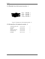
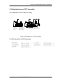
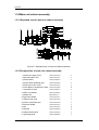
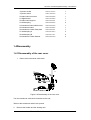
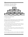
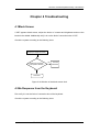
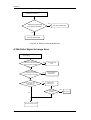
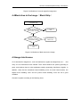
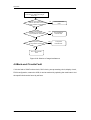
1
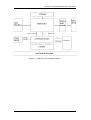
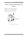
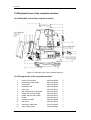
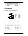
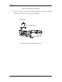
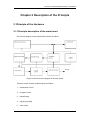
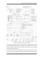
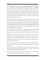
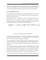
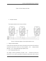
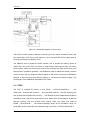
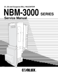
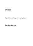
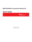
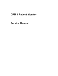
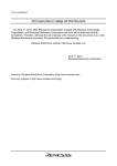
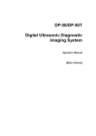
DP-3300/DP-3200 Digital Ultrasonic Imaging System Service Manual Diagnostic © 2005-2006 Shenzhen Mindray Bio-medical Electronics Co., Ltd. All rights Reserved. Product Information Product Name: Digital Ultrasonic Diagnostic Imaging System Model: DP-3300 Issued date of this manual: 2006-08 Version: 1.1 Intellectual Property Statement SHENZHEN MINDRAY BIO-MEDICAL ELECTRONICS CO., LTD. (hereinafter called Mindray) owns the intellectual property rights to this Mindray product and this manual. This manual may refer to information protected by copyrights or patents and does not convey any license under the patent rights of Mindray, nor the rights of others. Mindray does not assume any liability arising out of any infringements of patents or other rights of third parties. Mindray intends to maintain the contents of this manual as confidential information. Disclosure of the information in this manual in any manner whatsoever without the written permission of Mindray is strictly forbidden. Release, amendment, reproduction, distribution, rent, adaptation and translation of this manual in any manner whatsoever without the written permission of Mindray is strictly forbidden. DP-3300/DP-3200 Installation Manual (V1.1) I , , , , are the registered trademarks or trademarks owned by Mindray in China and other countries. All other trademarks that appear in this manual are used only for editorial purposes without the intention of improperly using them. They are the property of their respective owners. II DP-3300/DP-3200 Installation Manual (V1.1) Responsibility on the Manufacturer Party Contents of this manual are subject to changes without prior notice. All information contained in this manual is believed to be correct. Mindray shall not be liable for errors contained herein nor for incidental or consequential damages in connection with the furnishing, performance, or use of this manual. Mindray is responsible for safety, reliability and performance of this product only in the condition that: • all installation operations, expansions, changes, modifications and repairs of this product are conducted by Mindray authorized personnel; • the electrical installation of the relevant room complies with the applicable national and local requirements; • the product is used in accordance with the instructions for use. WARNING: It is important for the hospital or organization that employs this equipment to carry out a reasonable service/maintenance plan. Neglect of this may result in machine breakdown or injury of human health. Warranty THIS WARRANTY IS EXCLUSIVE AND IS IN LIEU OF ALL OTHER WARRANTIES, EXPRESSED OR IMPLIED, INCLUDING WARRANTIES OF MERCHANTABILITY OR FITNESS FOR ANY PARTICULAR PURPOSE. Exemptions DP-3300/DP-3200 Installation Manual (V1.1) III Mindray's obligation or liability under this warranty does not include any transportation or other charges or liability for direct, indirect or consequential damages or delay resulting from the improper use or application of the product or the use of parts or accessories not approved by Mindray or repairs by people other than Mindray authorized personnel. This warranty shall not extend to: any Mindray product which has been subjected to misuse, negligence or accident; any Mindray product from which Mindray's original serial number tag or product identification markings have been altered or removed; any product of any other manufacturer. Return Policy Return Procedure In the event that it becomes necessary to return this product or part of this product to Mindray, the following procedure should be followed: 1. Obtain return authorization: Contact the Mindray Service Department and obtain a Customer Service Authorization (Mindray) number. The Mindray number must appear on the outside of the shipping container. Returned shipments will not be accepted if the Mindray number is not clearly visible. Please provide the model number, serial number, and a brief description of the reason for return. 2. Freight policy: The customer is responsible for freight charges when this product is shipped to Mindray for service (this includes customs charges). 3. Return address: Please send the part(s) or equipment to the address offered by Customer Service department IV DP-3300/DP-3200 Installation Manual (V1.1) Company Contact Manufacture: Address: Shenzhen Mindray Bio-Medical Electronics Co., Ltd. Mindray Building, Keji 12th Road South, Hi-tech Industrial Park, Nanshan, Shenzhen, P.R.China,518057 Phone: +86 755 26582479 26582888 Fax: +86 755 26582500 26582501 ECRepresentative: Address: Phone: Fax: Shanghai International Holding Corp. GmbH(Europe) Eiffestrasse 80, 20537 Hamburg Germany 0049-40-2513175 0049-40-255726 DP-3300/DP-3200 Installation Manual (V1.1) V Return Policy Return Procedure In the event that it becomes necessary to return a unit to Mindray, the following procedure should be followed: 4. Obtain return authorization. Contact the Mindray Service Department and obtain a Customer Service Authorization (Mindray) number. The Mindray number must appear on the outside of the shipping container. Return shipments will not be accepted if the Mindray number is not clearly visible. Please provide the model number, serial number, and a brief description of the reason for return. 5. Freight policy. The customer is responsible for freight charges when equipment is shipped to Mindray for service (this includes customs charges). Company Contact Address: Mindray Building, 12th Keji Road South, Hi-tech Industrial Park, Nanshan, Shenzhen, P.R.China VI Phone: +86 755 26582888 Fax: +86 755 26582680 DP-3300/DP-3200 Installation Manual (V1.1) Safety Precautions Meaning of Signal Words In this manual, the signal words DANGER, WARNING, and CAUTION are used regarding safety and other important instructions. The signal words and their meanings are defined as follows. Please understand their meanings clearly before reading this manual. Signal word Meaning DANGER Indicates an imminently hazardous situation which, if not avoided, will result in death or serious injury. WARNING Indicates a potentially hazardous situation which, if not avoided, could result in death or serious injury. CAUTION Indicates a potentially hazardous situation which, if not avoided, may result in minor or moderate injury. CAUTION Indicates a potentially hazardous situation which, if not avoided, may result in property damage. Meaning of Safety Symbols Symbol Description Type-BF applied part "Attention" (Refer to the operation manual.) Safety Precautions Please observe the following precautions to ensure patient and operator safety when using this system. DP-3300/DP-3200 Installation Manual (V1.1) VII CAUTION: 1. Display the most suitable image and select the most suitable measurement mode for the intended measurement. The results must be determined by a specialist. 2. The basic measurement results are not displayed in the exam report. 3. Be sure to perform measurement within images. If the area is outside the image, incorrect diagnosis may result. 4. The detailed precautions for each measurement are described in the corresponding section. Read and understand these precautions before performing the measurement. 5. Data in temporary storage areas, such as the CINE memory, is deleted when the power supply is turned OFF or when the Patient switch is pressed. Such data may also occasionally be deleted due to accidents. To minimize the possibility of reexamination being required as a result of unintended data deletion, back up the required images on external storage media. 6. Refer to the Operation Manual (Fundamentals) for precautions regarding the use of this system. VIII DP-3300/DP-3200 Installation Manual (V1.1) DP-3300/DP-3200 Service Manual(V1.1) I Contents Contents RETURN POLICY.......................................................................................................................VI SAFETY PRECAUTIONS.........................................................................................................VII MEANING OF SIGNAL WORDS............................................................................................................VII MEANING OF SAFETY SYMBOLS.........................................................................................................VII SAFETY PRECAUTIONS......................................................................................................................VII CONTENTS.....................................................................................................................................1 CHAPTER 1 OVERVIEW ............................................................................................................1 1.1 FUNCTION INTRODUCTION................................................................................................................1 1.2 INTRODUCTION OF COMPLETE MACHINE.............................................................................................1 1.2.1 Basic features............................................................................................................................1 1.2.2 Basic composition.....................................................................................................................2 STRUCTURE AND ASSEMBLY/DISASSEMBLY OF THE MACHINE ...............................1 1.3 STRUCTURE OF THE COMPLETE MACHINE...........................................................................................1 1.3.1 Appearance view of the main unit............................................................................................1 1.3.2 Exploded view of the complete machine..................................................................................2 1.3.3 Keyboard assembly...................................................................................................................3 1.3.4 Exploded view of CRT assembly..............................................................................................5 1.3.5 Main unit cabinet assembly.......................................................................................................6 1.4 DISASSEMBLY................................................................................................................................7 1.4.1 Disassembly of the rear cover...................................................................................................7 DP-3300/DP-3200 Service Manual(V1.1) 1 Contents 1.4.2 Disassembly of the cabinet tail board.......................................................................................9 1.4.3 Disassembly of the cabinet rear cover......................................................................................9 1.4.4 Disassembly of the power board.............................................................................................10 1.4.5 Disassembly of the main board and the transducer board......................................................13 1.4.6 Disassembly of CRT, CRT adjustment board and the connection board of the main unit ....17 1.4.7 Disassembly of CRT screen filter...........................................................................................21 1.4.8 Disassembly of the keyboard, trackball and buzzer...............................................................22 1.4.9 Disassembly of the fan............................................................................................................27 1.4.10 Remove USB extension wire................................................................................................28 CHAPTER 2 DESCRIPTION OF THE PRINCIPLE................................................................1 2.1 PRINCIPLE OF THE HARDWARE..........................................................................................................1 2.1.1 Principle description of the main board....................................................................................1 2.1.2 Working principle of CPU.......................................................................................................11 2.2 PRINCIPLE OF THE SOFTWARE.........................................................................................................15 2.2.1 Features and functions of the real-time operating system......................................................15 2.2.2 Description of the system software.........................................................................................16 CHAPTER 3 SYSTEM START-UP AND UPGRADE................................................................1 3.1 SYSTEM START-UP..........................................................................................................................1 3.2 SOFTWARE UPGRADING...................................................................................................................1 3.2.1 Entering the upgrading procedure.............................................................................................1 3.2.2 Upgrading operation..................................................................................................................2 CHAPTER 4 TROUBLESHOOTING..........................................................................................1 2 DP-3300/DP-3200 Service Manual(V1.1) Contents 4.1 BLACK SCREEN..............................................................................................................................1 4.2 NO RESPONSE FROM THE KEYBOARD.................................................................................................1 4.3 NO ECHO SIGNAL IN IMAGE AREA....................................................................................................2 4.4 BLACK AREA IN THE IMAGE(BLACK STRIP)..................................................................................3 4.5 IMAGE INTERFERENCE......................................................................................................................3 4.6 BACK-END CIRCUITS FAULT.............................................................................................................4 4.7 OTHER FAULTS..............................................................................................................................5 CHAPTER 5 MAINTENANCE AND CLEANING....................................................................1 5.1 MAINTENANCE TO BE PERFORMED BY USER......................................................................................1 5.1.1 Cleaning the system..................................................................................................................1 5.1.2 Creating a backup copy of the system hard disk......................................................................3 5.2 MAINTENANCE TO BE PERFORMED BY SERVICE PERSONNEL.................................................................3 DP-3300/DP-3200 Service Manual(V1.1) 3 Structure and Assembly/Disassembly of the Machine Chapter 1 Overview 1.1Function Introduction The digital portable ultrasound diagnostic system DP-3300/3200 is intended to use for the following studies: fetal organs, abdomen, pediatrics, small parts, neonatal cephalic, transvaginal, transrectal, peripheral vascular, superficial and conventional musculoskeletal , etc. The Digital Ultrasonic Diagnostic System DP-3300/3200 is intended to use for the examinations such as abdomen, gynecology, obstetrics, small parts, and orthopedics. The DP-3300 system has the measurement and calculation functions of abdomen, gynecology, obstetrics, and orthopedics, and the DP-3200 system has the measurement and calculation functions of abdomen and obstetrics. 1.2Introduction of Complete Machine The DP-3300/3200 system is a digital portable ultrasound diagnostic system, which is compact and cost-effective. The DP-3300/3200 system can work with three types of transducers ( big convex array, linear array and intra-cavity ) , and can be used for examinations of abdomen, gynecology, obstetrics, urology, pediatrics, small parts and intra-cavity. This system adopts the imaging technologies such as digital beamforming, continuous dynamic focusing, odd-even line discrepancy elimination, and multiple-focus splicing. It has the functions of monitor output, performance testing report, and video printing. 1.2.1Basic features 1. Supports the convex and linear array transducers 2. Supports the real-time adjustment of imaging parameters, so that the optimal images can be acquired; 3. Transducer frequency: 2MHZ to 12MHZ; DP-3300/DP-3200 Service Manual(V1.1) 1-1 Overview 4. One transducer socket(two sockets can be installed); 5. Frequency-conversion B/M mode imaging; 6. B Cine review; 7. VGA display, 640*480; 8. VIDEO outlet, PAL/NTSC optional; 9. Video print control port; 10. USB interface(optional); 11. Ethernet interface(DICOM3.0)(optional); 12. Self-diagnosis; performance testing report. 1.2.2Basic composition The system consists of transducer, transducer board, main board, connection board, keyboard, power supply, monitor, software, and mechanical structure. The diagram of the complete machine is shown as follows: 1-2 DP-3300/DP-3200 Service Manual(V1.1) Structure and Assembly/Disassembly of the Machine Figure 1-1 Diagram of the complete machine DP-3300/DP-3200 Service Manual(V1.1) 1-3 Structure and Assembly/Disassembly of the Machine Structure and Assembly/Disassembly of the Machine 1.3Structure of the Complete Machine 1.3.1Appearance view of the main unit Figure 2-2 Appearance view of the main unit DP-3300/DP-3200 Service Manual(V1.1) 2-1 Overview 1.3.2Exploded view of the complete machine 1.3.2.1Exploded view of the complete machine Figure 2-3 Exploded view of the complete machine 1.3.2.2Components of the complete machine 1 2 3 4 5 6 7 8 9 10 11 12 13 2-2 knobs of the monitor screen filter fixing buckle screen filter keyboard hook front cover anti-collision pad of keyboard rubber cap A of the handle rubber cap B of the handle handle transducer holder rear cover transducer cable hook cable winding rack 2302-20-29084 9901-20-23950 2302-20-34425 2302-20-29092 2302-20-34401 2302-20-29091 2302-20-34471 2302-20-34472 2302-20-34470 2302-20-29082 2302-20-29079 2102-30-16949 2302-20-29083 DP-3300/DP-3200 Service Manual(V1.1) 2 2 1 1 1 2 1 1 1 1 1 1 2 Structure and Assembly/Disassembly of the Machine 14 15 16 17 18 rubber cap of cable winding rack hook holder rubber pad of bottom plate bottom plate cover of USB interface 2302-20-29088 2302-20-29085 2302-20-29087 2302-20-34469 2302-20-34449 2 1 4 1 2 1.3.3Keyboard assembly 1.3.3.1Exploded view of the keyboard assembly(1) 3 4 5 1 7 8 9 6 2 1. 键盘上盖组件 2. 键盘下盖组件 3. 键盘硅胶帽 4. 键盘拨钮 5. 键盘旋钮A 6. 空心轴 7. 限位件 8. 压簧 9. 按键扣 10. 按键板连接线 2302- 30- 34427 2302- 30- 34484 2300- 20- 29076 2300- 20- 29074 2300- 20- 29071 2300- 20- 29067 2300- 20- 29066 2300- 20- 29065 2300- 20- 29064 2300- 20- 29139 1 1 2 4 1 1 1 1 1 1 Figure 2-4 Exploded view of the keyboard assembly(1) 1.3.3.2Composition of the keyboard assembly(1) 1 2 3 4 5 6 7 8 9 keyboard upper cover assembly keyboard lower cover assembly keyboard silicone rubber cap keyboard toggle switch keyboard knob A hollow shaft position limiter compressing spring keyboard buckle 2302-30-34427 2302-30-34484 2302-20-29076 2302-20-29074 2302-20-29071 2302-20-29067 2302-20-29066 2302-20-29065 2302-20-29064 DP-3300/DP-3200 Service Manual(V1.1) 1 1 2 4 1 1 1 1 1 2-3 Overview 1.3.3.3Exploded view of the keyboard assembly(2) 1 2 6 3 4 5 1. 键盘上盖 2302- 20- 34400 2. 防尘片 2302- 20- 34423 3. 蜂鸣器 2300- 21- 29142 4. 硅胶按键 2302- 20- 34402 5. 键盘板 2302- 20- 34405 6. 轨迹球 0000- 10- 10893 7. 轨迹球连接线 2300- 20- 29144 1 1 1 1 1 1 1 Figure 2-5 Exploded view of the keyboard assembly(2) 1.3.3.4Composition of the keyboard assembly(2) 1 keyboard upper cover 2 dust plate 3 buzzer 4 silicone rubber key 5 keyboard PCB 6 trackball 2-4 2302-20-34400 2302-20-34423 2302-21-29142 2302-20-34402 2302-20-34405 0000-10-10893 1 1 1 1 1 1 DP-3300/DP-3200 Service Manual(V1.1) Structure and Assembly/Disassembly of the Machine 1.3.4Exploded view of CRT assembly 1.3.4.1Exploded view of CRT assembly 1 2 3 4 5 1. CRT组件 2300- 21- 29149 1 2. CRT固定框 2300- 20- 29094 1 3. CRT绝缘垫片 2300- 20- 29095 1 4. 手柄固定架2 2300- 20- 29108 1 5. 防护板 2300- 20- 29109 1 Figure 2-6 Exploded view of CRT assembly 1.3.4.2Composition of CRT assembly DP-3300/DP-3200 Service Manual(V1.1) 2-5 Overview 1.3.5Main unit cabinet assembly 1.3.5.1Exploded view of main unit cabinet assembly 6 7 8 1 2 3 9 4 5 10 24 25 26 27 28 29 11 12 13 14153016 171819 20 21 22 23 Figure 2-7 Exploded view of main unit cabinet assembly 1.3.5.2Composition of main unit cabinet assembly 1 power box upper cover 2 fan connection wire 3 power board 4 power board shielding pad 2302-20-29194 2302-20-29141 2302-20-29059 2302-20-29202 2302-20-29195 5 power box lower cover 6 cover plate of transducer socket 2302-20-34448 2302-30-29053 7 connection board 8 main unit cabinet 9 plastic slot 10 right wind shield 11 cabinet rear cover 12 power connection wire 13 left wind shield 14 fan 15 fan pad 16 cabinet tail board A 17 grounding pole 2-6 2302-20-29096 M90-000115--2302-20-29113 2302-20-29104 2302-20-29140 2302-20-29107 2302-20-29143 2302-20-29099 2302-20-34450 0509-20-00098 DP-3300/DP-3200 Service Manual(V1.1) 1 1 1 1 1 2 1 1 1 1 1 1 1 3 3 1 1 Structure and Assembly/Disassembly of the Machine 18 power socket 19 power switch 20 main board connector 21 digital board 22 main board support 23 shield spring 24 transducer board shield cover 25 transducer board 26 transducer socket fixed plate 27 shield spring A 28 shield spring B 29 transducer socket fastener 2302-21-29147 2100-10-07943 2302-20-29208 2302-30-34403 2302-20-29110 2302-20-29245 2302-20-29198 2302-30-34407 2302-20-29101 2102-20-16918 2102-20-17113 2302-20-29199 1 1 1 1 1 2 1 1 1 4 4 2 1.4Disassembly 1.4.1Disassembly of the rear cover 1. Remove the transducer cable hook (1) (2) Figure 2-8 Disassembly of the rear cover Turn the transducer cable hook clockwise to the end; Take out the transducer cable hook upward. 2. Remove the handle and the winding rack DP-3300/DP-3200 Service Manual(V1.1) 2-7 Overview Pull out the handle rubber cap A&B and the winding rack rubber cap; Remove the two fixing screws M4x16, and then take out the handle; Remove the two fixing screws M4x12, and then take out the winding rack. winding rack rubber cap handle rubber cap winding rack rubber cap Figure 2-9 Remove the handle and winding rack 3. Remove the rear cover (1) 2-8 DP-3300/DP-3200 Service Manual(V1.1) Structure and Assembly/Disassembly of the Machine Figure 2-10 Remove the rear cover Uplift the tail of the rear cover forcibly; Move the rear cover backwards to remove it. 1.4.2Disassembly of the cabinet tail board 1. Remove the rear cover; 2. Disconnect the fan connector of the tail board; 3. Remove 8 M3X6 screws fixing the tail board and 2 M3X6 screws fixing the main board; 4. Disconnect the power wire connector, move the tail board backward to take it out. Figure 2-11 Disassembly of the cabinet tail board 1.4.3Disassembly of the cabinet rear cover 1. Remove the assembly of the cabinet tail board; DP-3300/DP-3200 Service Manual(V1.1) 2-9 Overview 2. Disconnect the fan connector of the rear cover; 3. Remove 9 M3X6 screws fixing the rear cover and take out the rear cover. Figure 2-12 Disassembly of the cabinet rear cover 1.4.4Disassembly of the power board 2-10 1. Remove the assembly of cabinet rear cover; 2. Pull out the assembly of the power board; DP-3300/DP-3200 Service Manual(V1.1) Structure and Assembly/Disassembly of the Machine Figure 2-13 Disassembly of the power board 3. Remove 6 M3X6 screws fixing the power box upper cover, and open the upper cover; 4. Disconnect the fan connector of the power board; M DP-3300/DP-3200 Service Manual(V1.1) 2-11 Overview Figure 2-14 Disconnect the fan connector 5. Remove 7 M3X8 screws fixing the power board and take out the power board; Figure 2-15 Disassembly of the power board 2-12 DP-3300/DP-3200 Service Manual(V1.1) Structure and Assembly/Disassembly of the Machine 1.4.5Disassembly of the main board and the transducer board 1. Disassemble the rear cover to take out the assemblies of the tail board and the back board; 2. Remove 3 M3X8 screws fixing the holder of the transducer cable hook and take out the holder; Figure 2-16 Remove the holder of the transducer cable hook 3. Remove the USB wire connector; 4. Remove 8 M3X6 screws fixing the holder and one M3X6 screw fixing the main board; DP-3300/DP-3200 Service Manual(V1.1) 2-13 Overview Figure 2-17 Disassembly of the main board and the transducer board(1) Figure 2-18 Disassembly of the main board and the transducer board(2) 5. 2-14 Pull out the assemblies of the main board and the transducer board backward; DP-3300/DP-3200 Service Manual(V1.1) Structure and Assembly/Disassembly of the Machine Figure 2-19 Disassembly of the main board and the transducer board(3) 6. Remove 7 M3X6 screws connecting the assemblies of the main board and the transducer board, and disassemble the main board; Figure 2-20 Disassembly of the main board and the transducer board(4) 7. Remove 8 M3X6 screws fixing the transducer board shield cover; DP-3300/DP-3200 Service Manual(V1.1) 2-15 Overview Figure 2-21 Disassembly of the main board and the transducer board(5) 8. Remove 4 M3X6 screws fixing the connection board of the transducer socket, and remove the transducer board; Figure 2-22 Disassembly of the main board and the transducer board(6) 2-16 DP-3300/DP-3200 Service Manual(V1.1) Structure and Assembly/Disassembly of the Machine 1.4.6Disassembly of CRT, CRT adjustment board and the connection board of the main unit 1. Disassemble the rear cover to take out the assemblies of the tail board and the back board; 2. Remove 4 PT4X14 screws fixing the front cover; Figure 2-23 Remove 4 PT4X14 screws fixing the front cover 3. Disconnect CRT signal cable, keyboard connection wire, CRT power wire and CRT adjustment board connector; DP-3300/DP-3200 Service Manual(V1.1) 2-17 Overview Figure 2-24 Disconnect the connection wires 4. Remove 8 M3X8 screws fixing CRT assembly and take out CRT; Figure 2-25 Remove CRT assembly 2-18 DP-3300/DP-3200 Service Manual(V1.1) Structure and Assembly/Disassembly of the Machine 5. Remove CRT adjustment knobs and 4 PT3X8 screws fixing CRT adjustment board, and then remove the CRT adjustment board; DP-3300/DP-3200 Service Manual(V1.1) 2-19 Overview Figure 2-26 Remove CRT adjustment knobs 6. Remove 8 M3X6 screws fixing the connection board of the main unit, and then remove the connection board of the main unit. Figure 2-27 Remove the connection board of the main unit 1.4.7Disassembly of CRT screen filter 2-20 1. Slide the two screen filter buckles outward and pull them out; 2. Pull out the upper screen filter outward and uplift it, and then take it out. DP-3300/DP-3200 Service Manual(V1.1) Structure and Assembly/Disassembly of the Machine (3) (1) (1) (2) (4) (2) ( 3) ( 2) ( 2) ( 1) ( 1) ( 4) Figure 2-28 Disassembly of CRT screen filter 1.4.8Disassembly of the keyboard, trackball and buzzer 1. Remove the two keyboard silicone rubber caps, and then remove 2 M3×6 screws fixing the keyboard upper cover; Figure 2-29 Remove the silicone rubber caps DP-3300/DP-3200 Service Manual(V1.1) 2-21 Overview 2. Open the keyboard upper cover by hands forcibly at the positions of arrows; Figure 2-30 Disassembly of the keyboard upper cover 3. Disconnect the connection wire connector of the keyboard, and remove the keyboard upper cover; 2-22 DP-3300/DP-3200 Service Manual(V1.1) Structure and Assembly/Disassembly of the Machine Figure 2-31 Disassembly of the keyboard upper cover 4. Disconnect the connection wire connector of the trackball, remove 4 ST3x14 self-threading screws fixing the trackball, and remove the trackball; DP-3300/DP-3200 Service Manual(V1.1) 2-23 Overview Figure 2-32 Disassembly of the trackball 5. Pull out keyboard knobs A, B, C and 6 keyboard toggle switches; Figure 2-33 Remove the keyboard knobs and switches 2-24 DP-3300/DP-3200 Service Manual(V1.1) Structure and Assembly/Disassembly of the Machine 6. Disconnect the connection wire connector of the buzzer, remove 14 ST3x8 screws fixing the keyboard, and remove the silicone rubber keys to take out the keyboard PCB, and then remove 2 ST2x6 screws fixing the buzzer to take out the buzzer; ST3x8 screw ( 14 ) Keyboard PCB Connection wire of buzzer Silicone rubber key ST2x6 screw ( 2 ) Buzzer Figure 2-34 Remove the buzzer DP-3300/DP-3200 Service Manual(V1.1) 2-25 Overview 1.4.9Disassembly of the fan 1. Remove the rear cover; 2. Disconnect the tail board fan connector and remove 4 M3X30 screws, and then remove the tail board fan; Figure 2-35 Disassembly of the tail board fan 3. Disconnect the back board fan connector and remove 8 M3X30 screws, and then remove the back board fan. 2-26 DP-3300/DP-3200 Service Manual(V1.1) Structure and Assembly/Disassembly of the Machine Figure 2-36 Disassembly of the back board fan 1.4.10Remove USB extension wire 1. Disassemble the rear cover, the cabinet tail board assembly, the cabinet back board assembly and the front cover assembly; 2. Remove 7 PT3x8 screws fixing the cabinet bottom board, and remove the cabinet; PT3*8 screws(8) DP-3300/DP-3200 Service Manual(V1.1) 2-27 Overview Figure 2-37 Disassemble the cabinet 3. Remove 2 PT3x 8 screws fixing the USB compressor, and remove the USB compressor, and then take out the USB extension wire. PT3x8 screw USB compressor Figure 2-38 Remove the USB extension wire 2-28 DP-3300/DP-3200 Service Manual(V1.1) Structure and Assembly/Disassembly of the Machine Chapter 2 Description of the Principle 2.1Principle of the Hardware 2.1.1Principle description of the main board The function diagram of the main board is shown as follows: Figure 3-39 The function diagram of the main board There are seven function modules shown as follows: 1. transmission circuit 2. reception circuit 3. beamforming 4. signal processing 5. Cine review DP-3300/DP-3200 Service Manual(V1.1) 3-1 Overview 6. DSC 7. post-processing and display circuit 2.1.1.1Schematic diagram of the main board The main board can realize the functions such as transmission, reception, beamforming, signal processing, DSC, Cine review, networking, USB, VIDEO, and VGA, etc. The hardware of the main board supports an transmission circuit, which is divided into an low-voltage transmission pulse drive circuit and 80-channel high-voltage transmission pulse drive circuit. The transmission is realized by the EP1S10 ( FPGA of Stratix series), and its sequence is controlled by the FPGA as well. The high voltage isolation and reception selection circuit is mainly used for the isolation between the reception circuit and the high voltage generated by the transmission circuit. The conversion among the elements and channels is directly executed by the high voltage isolation circuit rather than the high voltage switch. Therefore the high voltage isolation circuit also has the function of the reception selection circuit, and the control signal of the reception selection circuit is provided by EP1S10. The voltage-controlled gain amplifier circuit can realize the functions of low noise preamplifier and voltage-controlled gain amplifier. The DP-3300/3200 does not fold the reception channels. The A/D circuit is used for the analog-to-digital conversion of the output of the voltage-controlled gain amplifier circuit. The output is connected to EP1S10, and the low-pass filter before the A/D circuit is used for anti-aliasing filtering. 3-2 DP-3300/DP-3200 Service Manual(V1.1) Structure and Assembly/Disassembly of the Machine Figure 3-40 Schematic diagram of the main board The ATGC-DAC circuit mainly uses a DAC to generate the voltage-controlled signal of the voltage-controlled gain amplifier. In addition, this dual-channel DAC can also generate a voltage-controlled signal for controlling the PHV variation, and the input signal of the DAC is provided by EP1S10. EP1S10F672C7 is the FPGA of the Stratix series made by ALTERA. It features 1M gate, 10,000 LE, 94 blocks of 512bits RAM, 60 blocks of 4Kbits RAM, one block of 512Kbits DP-3300/DP-3200 Service Manual(V1.1) 3-3 Overview RAM, and six DSP blocks (each DSP block can be configured into one 36×36 multiplier, four 18×18 multipliers or eight 9×9 multipliers). It also supports various 3.3V differential I/Os and DDR interface. In the DP-3300/3200, EP1S10F672C7 is the control core for the front-end circuit, respectively providing the transmission sequence control of the transmission circuit, the control of the reception selection circuit, the gain adjustment control of the voltage controlled gain amplifier, the adjustment control of PHV, the beamforming logic, and the signal processing logic , etc. Moreover, the phase-locked loop output of EP1S10F672C7 provides a 29.5MHz clock for PAL-system VIDEO signal and a 6MHz clock for USB control chip. The CINE review and post-processing functions are realized within one FPGA, which is the ACEX1K100FC484 made by ALTERA. The chip has two SDRAMs used as CINE review memory, and four SRAMs respectively used as frame correlation buffer, graphics memory, image memory and video signal buffer, thus generating the signals of frame correlation, graphics circuit, image storage VGA and VIDEO. In addition, this FPGA chip can also generate the horizontal and vertical synchronization signals for the VGA monitor and the control signal for the video printer. The function of the DSC circuit is realized in one FPGA, which is the ACEX1K100QC208 made by ALTERA. The chip has one 256k×16 SRAM used for the B-type DSC look-up table and the M-mode memory, and four 128k×8 SRAMs used for the B-mode DSC memory. The chip MCF5307, made by Motorola, is used as CPU and the control core of the DP3300/3200. The chip has SDRAM and FLASH as internal memory and Boot ROM, and it is externally connected with power detection A/D, watchdog, real-time clock and temperature detection circuit through IIC bus. The serial port for communicating with the keyboard is provided by the CPU. The chip CPLD provides the interfaces between the CPU and the external circuits, including the USB control interface, network control interface and FPGA configuration interface, etc. The DP-3300/3200 has two video DACs, one for generating the monochromatic VGA signal, and the other for generating the video signal. Since the system needs two video signal outputs, there are two operational amplifiers. The chip for network interface provides the functions of MAC and PHY, and it is externally connected with a network transformer to isolate the network signal. 3-4 DP-3300/DP-3200 Service Manual(V1.1) Structure and Assembly/Disassembly of the Machine The chip for USB interfaces controls the two USB interfaces and is connected with an external power management chip. Each USB interface can provide maximum 500mA. If the current exceeds 500mA, the power for USB interfaces will be cut off automatically. 2.1.1.2Transmission circuit The transmission circuit generates the high voltage transmission pulse for exciting the elements to generate the sound field. This system adopts the one-to-one fashion for the transmission circuit and elements. The transmission circuit is comprised of two parts: transmission sequence and transmission drive. The transmission sequence circuit generates the low voltage transmission pulse TPU [n..0], which passes the transmission drive and becomes the high voltage transmission pulse POUT [n..0] for driving the elements. Figure 3-41 the diagram of ultrasound transmission The elements have intrinsic spectrum, and changing the spectrum of the excitation signal can change the transmission spectrum, i.e., changing the spectrum of the transmission pulse. For the system, two types of adjustment are designed. One type of adjustment is to adjust the high level width of single transmission pulse. The narrower the high level width of transmission pulse, the wider the spectrum of transmission pulse. This type of adjustment is only used for the central frequency to become low. The other type of adjustment is realized by means of the transmission burst. The pulse count determines the transmission pulse width, and the pulse repetition period determines the central frequency of transmission pulse. The big transmission power can realize the free movement of the central frequency, but with sacrificing the transmission bandwidth, thus affecting the axial resolution. Therefore the pulse count is set to 2 or 3. To improve the lateral resolution, decreasing the side lobe can increase the transmissionDP-3300/DP-3200 Service Manual(V1.1) 3-5 Overview weighting circuit. If the transmission pulse width is different, the transmission energy is different. For the elements involving in the transmission, if the transmission pulses with different width are used to excite the elements, the transmission-weighting effect can be obtained. For single pulse transmission, since the adjustment of transmission pulse width is limited, the transmission weighting is only used for the transducers with low frequencies. For multiple pulse transmission, since the central frequency is determined by the pulse repetition period, the high level width of transmission pulse can be adjusted in a bigger range, and the transmission-weighting effect is better. The transmission weighting is used for all transducers. 2.1.1.3Reception circuit The reception circuit executes the selection on the reception elements, element echo amplification and AD conversion. The circuit is comprised of high voltage isolation and reception selection circuit, voltage-controlled gain amplifier, anti-aliasing filtering, AD and ATGC. The diagram of the reception circuit is shown as follows: 3-6 DP-3300/DP-3200 Service Manual(V1.1) Structure and Assembly/Disassembly of the Machine Figure 3-42 High voltage pulse output 2. Reception selection The reception selection circuit is shown as follows: Figure 3-43 Schematic diagram of the reception selection circuit 4. Voltage-controlled amplifier To make the echo signal match the monitor, the internal circuit structure of the machine is comprised of three parts, namely, low noise pre-amplifier ( LNP ) , voltage-controlled attenuator(VCA)and programmable gain amplifier (PGA). 5. ATGC voltage generating circuit The voltage of ATGC is generated by TLV5626 ( DAC ) . TLV5626 can provide twochannel DAC; one is used for generating PHV adjustment signal and the other is used for DP-3300/DP-3200 Service Manual(V1.1) 3-7 Overview sending the analog voltage required by the voltage-controlled amplifier. In practice, the internal 2.048V reference source is selected and after it is transformed through TLV5626, the external output voltage is 2 REF CODE [V ] . In theory, the 0 x1000 output range of its global transform is between 0V and 4.096V, which can meet the requirements that the control voltage of ATGC is between 0V and 3V, as well as the requirements that the adjustment signal of PHV is between 0V and 4V. Figure 3-44 ATGC voltage generating circuit 6. Low-pass filter and stopping direct current circuit The low-pass filter is used to provide the anti-aliasing filtering function for the ADC circuit. The stopping direct current circuit is used for the direct-current component of the output signal of the voltage-controlled gain amplifier circuit, enabling it to couple the direct current level required by the ADC circuit before it enters the ADC. 7. A/D circuit MAX1196 made by MAXIM is used as ADC. In practice, power is supplied respectively to its analog and digital portions, and the analog portion is supplied with + 3V and digital portion with +3.3V. The MAX1196 provides a dual-channel difference input ADC. The output port of the digital signal after AD conversion is time-sharing multiplex, and the sampling rate is up to 40MHz and the resolution is 8 bits, which can meet the requirements of the system. In addition, the range of the difference input signal is ±1 V, which can also meet the requirement of 2VP-P from the system. 2.1.1.4Beamforming The amplified echo signal passes the ADC circuit to complete the analog-digital 3-8 DP-3300/DP-3200 Service Manual(V1.1) Structure and Assembly/Disassembly of the Machine conversion, and then passes the zero adjustment circuit to automatically eliminate the direct current offset. After the echo signal for beamforming goes through delay apodization summation, the composite data pass the dynamic aperture compensation circuit and then the beamforming output is obtained. The circuits have the same structure, and their characteristics are determined by the applied reception parameters, such as the delay focusing data and weighting data. The beamforming circuit is realized in a FPGA, and EP1S10 F672C7 made by ALTERA is used as the FPGA. EP1S10F672C7 is one FPGA of the Stratix series made by ALTERA. It features 1M gate, 10,000 LE, 94 blocks of 512bits RAM, 60 blocks of 4Kbits RAM, one block of 512Kbits RAM, and six DSP blocks (each DSP block can be configured into one 36×36 multiplier, four 18×18 multipliers or eight 9×9 multipliers). It also supports various 3.3V differential I/Os and DDR interface. In addition, EP1S10F672C7 also supports the DDR interface. 2.1.1.5Signal processing There are modules shown as follows: dynamic filter, envelope detection, logarithm compression, DTGC, odd-even line compensation, AGC, second-time sampling, dynamic range adjustment, edge enhancement, multiple-focus splicing, and axial smooth filter. 2.1.1.6Cine review This circuit is realized by means of FPGA(ACEX1K100FC484-3), SRAM(W24010A15)and SDRAM(HY57V641620HG-T-H). See the figure as follows: DP-3300/DP-3200 Service Manual(V1.1) 3-9 Overview Figure 3-7 Schematic diagram of Cine review The FPGA is mainly used to realize the control logic of the frame correlation circuit, and the control logic of the Cine review memory. It is to note that this FPGA is also used for the post-processing and display circuit. The SRAM is used to realize the buffer function, and to provide the memory space of 128k*8 bits, and it can store one frame of high-density scanning line data. The frame buffer always stores the most recent frame of the scanning line data which have gone through frame correlation operation. The SDRAM is used to realize the memory function of Cine review, and to provide the memory space of 4M*16 bits. One piece of SDRAM is adopted to store 64-frame high-density images or 128-frame low-density images. The control logic of the SDRAM is generated by the FPGA. 2.1.1.7DSC The DSC is realized by means of one FPGA ( ACEX1K100QC208-3 ) , four W24L010A(B-mode DSC memory), and one IS61LV25616L (B-mode scanning line look-up table and M-mode DSC memory). The M-MAX circuit is added before the M line correlation circuit, and the M-mode memory only stores the 512-line images, so that the M-mode memory and the B-mode DSC look-up table can share one 256K*16 SRAM ( IS61LV25616L ) . The M-MAX sampling circuit, M line correlation circuit, Mmode DSC and B-mode DSC are realized through one FPGA(ACEX1K100QC208-3). 3-10 DP-3300/DP-3200 Service Manual(V1.1) Structure and Assembly/Disassembly of the Machine 2.1.1.8Post-processing and display circuit The Cine review and post-processing circuit is realized by EP1K100FC484-3. The image effect is realized by means of the look-up table. One IS61LV25616L(256K*16)is used as graphics memory in the graphics circuit, and the CPU can directly access the graphics memory. One IS61LV25616L(256K*16)is used as buffer in the transform circuit of Vga to Video. The THS5641 is used as VGA DAC, as well as VIDEO DAC. Since the two-channel VIDEO signal is to be driven, the output of VIDEO DAC is to be driven by a two-channel amplifier. The LM6181 is used as the amplifier. This circuit adopts the 25MHz clock. The post-processing diagram is shown as follows: Figure 3-8 Schematic diagram of Cine review 2.1.2Working principle of CPU The computer system is the control core of the complete machine, and its hardware DP-3300/DP-3200 Service Manual(V1.1) 3-11 Overview design is used for the hardware support on the functions realized by the system software. 2.1.2.1System CPU MCF5307 made by MOTOROLA is used as the system CPU, and it features as follows: 1. 8 k bytes uniform cache (i.e. the data are with the instructions) 2. 4 k bytes on-chip SRAM (high speed SRAM, running with the core in the same frequency without waiting time) 3. integer/fraction product unit (similar to the DSP instruction) 4. hardware division unit 5. system tuning interface 6. supporting synchronous DRAM/asynchronous DRAM 7. four-channel DMA controller 8. two general timers 9. two full-duplex serial ports 10. IIC bus 11. parallel I/O port 12. system integration module (SIM) In the 90MHz core frequency, the processing capability of the chip 5307 is 75MIPS (dhrystone 2.1 testing standard), but for the chip 5206, it is 17 MIPS in the frequency of 33MHz. Therefore the operation capability of CPU is greatly boosted up. 2.1.2.2Reset logic The external reset of the MCF5307 is derived from two sources: watchdog and BDM port. The both sources can generate the reset signal, and they encounter in the CPLD and generate the /RSTI signal required by CPU. To ensure the correct reset of other portions of the system, the /RSTO signal outputted by CPU is used to reset other components. The CAT24C161 is used as reset/watchdog chip. 3-12 DP-3300/DP-3200 Service Manual(V1.1) Structure and Assembly/Disassembly of the Machine In the portable ultrasound diagnostic system, the watchdog is only used for power-on reset, so the SDA pin of the watchdog can be directly connected to a clock through CPLD. Therefore the watchdog will be disabled after the system is reset. 2.1.2.3System clock circuit The chip 5307 has the doubling circuit internally, so the core frequency of CPU is twice the external bus frequency. The external frequency of 45MHz is adopted, and the operating frequency of CPU is 90MHz. If a peripheral device operates synchronously with the CPU, the external frequency of 45MHz must be applied. The distribution of the 45MHz external frequency clock of CPU is shown below: Figure 3-9 CPU system clock distribution 2.1.2.4Voltage detection circuit The voltage detection circuit is designed for the detection of eight voltages of +5V,- 5V, + 1.5V, + 2.5V, + 3V, + 13.5V, +12V and PHV (programmable high voltage). Except the + 1.5V voltage, other voltages are converted into the + 2.5V voltage by means of voltage divider or inverter. PCF8591 is used as the voltage detection chip, which has 4-channel analog inputs. So two pieces of PCF8591 are required. LM4120 is used as the reference voltage source, supplying the +3.3V voltage. The + 3.3V reference voltage can tolerate certain forward bias. If the 2.5V voltage is set as the input voltage under detection, the overload range is 30% ( ( 3.3- DP-3300/DP-3200 Service Manual(V1.1) 3-13 Overview 2.5)/2.5=30%). 2.1.2.5Internal memory Two pieces of AM29LV641DH90REI are used as FLASH, with space of 8M WORDS and 16-bit port. HY57V641620HG-T-H is used as SDRAM, and its structure is 4 banks * 1M * 16 bits. Two pieces of HY57V641620HG-T-H are used to compose the SDRAM memory space of 4M LONG WORDS and 32-bit port. The MCF5307 serves as SDRAM controller, and can be connected with HY57V641620HG-T-H. 2.1.2.6Ethernet AX88796L made by AXIS is used as Ethernet interface, and it features as follows: 3. 10M/100M adaptive and physical layer interface; 4. NE2000 register-grade compatible; 5. internal 8K*16 BITS SRAM; 6. LOCAL BUS interface, seamlessly connecting with MCS51, ISA and 68K; 7. MII interface, connecting to other physical layers; To connect AX88796L with RJ45UTP ETHERNET CABLE, it only needs to connect the network transformer, and FM81-2319 is used as the network transformer. 2.1.2.7USB interface ISP1161A1 made by PHILIPS is used as USB interface, and SN75240PW is used to provide the transient interference suppression for the USB two-channel descending port. 2.1.2.8CPLD CPLD is mainly used for the following functions: 8. control logic of data buffer; 9. write protection logic for EEPROM and FLASH; 10. system reset logic; 3-14 DP-3300/DP-3200 Service Manual(V1.1) Structure and Assembly/Disassembly of the Machine 11. FPGA configuration logic; 12. IRQ distribution logic; 13. network card interface logic; 14. USB interface logic. 2.2Principle of the Software 2.2.1Features and functions of the real-time operating system The system is a real-time multitask embedded system supported by a real-time operating system. It is comprised of two parts: the real-time multitask operating system and system application program, and it features as follows: 15. Real-time 16. Responding to asynchronous events 17. Responding to synchronous events 18. Interrupt management 19. Definite conversion time and interrupt delay time 20. Preemptive sequence arrangement The operating system can realize the functions such as task conversion, task sequence arrangement, communications among tasks, synchronization, mutual repulsion and interrupt management, etc. DP-3300/DP-3200 Service Manual(V1.1) 3-15 Overview 2.2.2Description of the system software 2.2.2.1The structure of the system software information management interface management parameter management bottom hardware driver machine management preset data management UART 1 file management print management Figure 3-10 The structure of the system software 2.2.2.2Description of object functions 21. Information management The task of the information management object is to transfer and distribute information. The information is taken out from the system information box, and then distributed to other objects such as interface management and machine management. 2. Manager for booking and releasing information This information-releasing manager doesn’t generate a sample. However, it serves as an object in the system, managing the information booking or canceling the information booking, and releasing the information to the object that books the information. 3. Interface management object The task of the interface management object is to manage all the graphics elements on the screen, such as menu, dialogue box, image window, static text, edit window, valid curve and cursor, etc. 4. Machine management object The machine management object refers to a series of objects, which are aggregated based on the parameters and other objects related to hardware drivers. These objects 3-16 DP-3300/DP-3200 Service Manual(V1.1) Structure and Assembly/Disassembly of the Machine are designed to seal all the parameters and parameter operations that are related to machine characteristics. 5. Parameter management object The parameter management object is designed for retaining the parameters, such as the preset data, the current true data and the parameter output. Additionally, the parameter management object determines all the characteristics of the parameters. 6. Preset data management object The preset data management object is designed for managing all the preset data stored in the flash memory. The preset data are aggregated based on the exam modes, and then stored in the corresponding sectors. The preset data management object has a data buffer, which saves the preset data based on the current exam mode. 7. Hardware driver The hardware driver object is designed for driving the system hardware. It generally builds up its structure based on the functions. 8. File management object The file management object is designed for providing all operations related to file reading and writing and disks. It seals the functions related to the disks and files in the operating system. 9. Printing management object The printing management object is designed for providing all the printing operations of the ink-jet printer. It is used for sealing the functions related to the graph/text printer. In the system, the printing management object prints the diagnostic reports based on the printing template. 10. Serial port 1 The serial port 1 is used for managing the communications with the operation panel. 11. System mailbox HotMailBox DP-3300/DP-3200 Service Manual(V1.1) 3-17 Overview This mailbox is used for saving the information with first priority. Its data structure is FIFO rank. TheMailBox This mailbox is used for saving the information with common priority. Its data structure is FIFO rank. TheMailBox2 This mailbox is used for saving the information with minimum priority. Its data structure is FIFO rank. 3-18 DP-3300/DP-3200 Service Manual(V1.1) Structure and Assembly/Disassembly of the Machine Chapter 3 System Start-up and Upgrade 3.1System Start-up 1. The system completes the initialization of CPU, DRAM and chip selection; 2. The system copies the software codes solidified in the flash to DRAM; 3. The system runs the software in DRAM, configures CPU interrupt, and fills in the interrupt vector table; 4. The system configures the display circuit FPGA; 5. The system displays the start-up screen; 6. The system configures other circuit FPGA; 7. The system reads out the preset data, and based on the preset, selects the exam mode and the transducer; 8. The front end is initialized based on the selected transducer; 9. The system initializes the scanning and back-end parameters, opens the scanning interrupt and performs the image scanning. 3.2Software Upgrading Note: the system software can be upgraded only when the machine has the USB interface. 3.2.1Entering the upgrading procedure Entering the maintenance operation: click『File』key →click “preset” DP-3300/DP-3200 Service Manual(V1.1) 4-1 Overview →click “maintenance” →the password dialogue window pops up: Pl ease i nput password | OK Cancel Enter the password “23022378”, and click “OK” to enter the maintenance menu: Sys SW CI NE FPGA Ot her FPGA St art Logo Text Pri nt Font Def aul t Preset CI M Probe Dat a Mai nt enance Product Conf i gure Sys I nf o Gray Test Upgrade PI T Menu Sel f Di agnosi Ret urn 3.2.2Upgrading operation Each item in the upgrading submenu is used for the upgrading function. Perform the upgrading operation based on the different data that are described in the table below: Table 4-1 The relationship between functions and name extension Menu System software 4-2 Data Software File name extension UPG CINE FPGA Display circuit FPGA FP1 Other FPGA Other FPGA in the system FP2 DP-3300/DP-3200 Service Manual(V1.1) After upgrading Prompt on turning off the system Prompt on turning off the system Prompt on turning off the Structure and Assembly/Disassembly of the Machine Boot bitmap The image displayed when the system starts up. BMP Factory default setup the backup of factory DTA data in flash DTA Chinese entry Chinese entry data CIM Transducer’s data The data of the transducers supported PRB system The system resets automatically The system resets automatically The system resets automatically The system resets automatically The system software is taken as an example to describe the upgrading procedure: Put a U disk with UPG upgrading files into a USB interface. →Click “system software”, a file dialogue box pops up and opens: 1 Load Fi l e C: Dri ver: Pat h: C: Tot al Syst emUpdat e Fi l es:1 Name Type DP6600 UPG DP6600 . UPG Fi l es: Pat i ent Name Pati ent I D 3 Modi fy ti m e 04- 11- 20 14: 20 2 4 Cancel OK Hel p Figure 4-45 The screen for the software upgrading →Select the file to be upgraded in the dialogue box. The meaning of each item is described as follows: 1. Drive path 2. Directory path 3. Name of the selected file 4. File list DP-3300/DP-3200 Service Manual(V1.1) 4-3 Overview →Click OK button The system software will be upgraded. After the upgrading finishes, the system will prompt as follows: Updat e f i ni shed, pl ease repower! →Turn off the machine, and then after a while, turn it on again, OK. Note: After the upgrading finishes, for some data it needs to turn off the machine and turn it on again; however, for other data, the system will reset automatically to enable the upgraded data. 4-4 DP-3300/DP-3200 Service Manual(V1.1) Structure and Assembly/Disassembly of the Machine Chapter 4 Troubleshooting 4.1Black Screen If CRT appears black screen, adjust the knobs of contrast and brightness and tune the knobs in the middle. Additionally verify it is not the fault of connection wire of CRT. Check the system according to the following chart: No display or display abnormality Replace the main board. Is the problem resolved? Yes The main board's fault No CRT's fault Figure 5-46 Solution of the black screen fault 4.2No Response from the Keyboard First verify it is not the fault of connection wire of the keyboard. Check the system according to the following chart: DP-3300/DP-3200 Service Manual(V1.1) 5-1 Overview . Keyboard is abnormal Yes Replace the main board. Is the problem resolved? The main board's fault No The main panel's fault . Figure 5-47 Solution of the keyboard fault 4.3No Echo Signal in Image Area Al l B mo d e e ch o i ma g e s are missing. Replace the transducer and use the same connector. Is the problem resolved? Yes The transducer's fault No Connect different transducer connector. Yes Is the problem resolved? The transducer board's fault No Can the sound “chirp” be heard from the transducer? No Replace the power board. Yes Yes Is the problem resolved? yes No The main board's fault 5-2 DP-3300/DP-3200 Service Manual(V1.1) PHV's fault Structure and Assembly/Disassembly of the Machine Figure 5-48 Solution of no echo signal in image area 4.4Black Area in the Image(Black Strip) Black area in the B mode Image(Black Strip) Replace the transducer and use the same connector. Is the problem resolved? Yes The transducer's fault No Connect different transducer connector. Is the problem resolved? Yes The transducer board's fault No The main board's fault Figure 5-49 Solution of black area in the image 4.5Image Interference If it is abnormal in image area(such as interference, ripples and bright lines, etc.), first verify it is not interference from outside. Then check whether the system grounding is good, and whether there is other equipment nearby generating interference signals. In addition, verify that the transducer board shielding cover, the main board socket, the digital circuit shielding cover and the power board shielding cover are all in good condition. Check the system according to the following chart: DP-3300/DP-3200 Service Manual(V1.1) 5-3 Overview it is abnormal in image area (e.g. interference, ripples and bright lines, etc.) Replace the transducer and use the same connector. Is the problem resolved? Yes The transducer's fault No Connect different transducer connector. Is the problem resolved? Yes The transducer board's fault No Replace power board. Is the problem resolved? Yes The power board's fault. No The main board's fault Figure 5-50 Solution of image interference 4.6Back-end Circuits Fault If it is the fault of CINE review circuit, DSC circuit, post-processing circuit, display circuit, FPGA configuration, network or USB, it can be resolved by replacing the main board. And the specific fault can be found by self-test. 5-4 DP-3300/DP-3200 Service Manual(V1.1) Structure and Assembly/Disassembly of the Machine 4.7Other Faults Table 5-2 Other faults list No 1 Fault The fan work. doesn’t Cause ◆+12V power is abnormal ◆The cable’s fault ◆The fan’s fault 2 ◆The cable’s fault USB fault Remark Supply the + 12V power directly by the power board, check the +12V voltage in the power board. ◆Replace USB interface cable ◆The main board is abnormal ◆Check the main board ◆The software doesn’t support U disk or the printer. ◆Use U disk printer 3 Video output fault ◆Video cable’s fault ( inside the main board) of model ◆Check corresponding cable or the specified the video ◆The main board is abnormal 4 Network fault ◆The main board is abnormal ◆Check the main board ◆First verify that the external network is connected correctly. DP-3300/DP-3200 Service Manual(V1.1) 5-5 Maintenance and Cleaning Chapter 5 Maintenance and Cleaning 5.1Maintenance to Be Performed By User 5.1.1Cleaning the system Warning: Before cleaning the system, be sure to turn off the power and disconnect the power cable from the outlet. Cleaning the machine when the power is “On” may result in electric shock. 1. Cleaning the transducer Perform the cleaning, disinfection and sterilization for the transducer according to the corresponding transducer’s manual. 2. Cleaning the transducer socket A. Use dry rag to wipe off the dirt on the transducer socket. B. If it is hard to get rid of the dirt, use the rag soaked the mild detergent to wipe off, then make the transducer socket air-dried. 3. Cleaning CRT Use the rag soaked the glass cleaner to wipe off CRT, and then make it air-dried. Note: Do not use the detergent of hydrocarbon or the detergent for OA device to clean CRT. Otherwise it may cause degradation of performance for CRT. 4. Cleaning the control panel, cover and bracket Use dry rag to clean the surface of the machine. Or use the rag dipped neutral detergent to wipe off the dirt, and then dry the machine by dry rag or make it air-dried. 5. Cleaning the trackball DP-3300/DP-3200 Service Manual (V1.1) 6-1 Overview a)Disassembling the trackball Press the bulges on the clamping ring by both hands and turn the ring about 45° clockwise until it lifts. Take out the ring and the rotary ball. Be careful not to drop the ball. Rotary ball Clamping ring Top cover b)Cleaning the trackball Clean the two long shafts, the bearing and the rotary ball with clean soft dry cloth or paper. Bearing Long shaft Long shaft c)Installing the trackball Put the rotary ball back in the trackball and then align the clamping ring click with the top cover notch. Press the bulges on the ring with both hands and turn the ring about 45° counterclockwise until the ring clicks. As the bulges are flush with the top cover, the ring is secured. 6-2 DP-3300/DP-3200 Service Manual(V1.1) Maintenance and Cleaning Clamping ring click Top cover notch Caution: 1. Be careful not to allow water or liquid to enter the system during cleaning, otherwise it may result in malfunction or electric shock. 2. To clean the connector, TGC controls and other connectors for the peripheral devices, contact the foreign sales distributor of Mindray. The cleaning done by the user may cause malfunction or degradation of performance. 5.1.2Creating a backup copy of the system hard disk To prevent any damage or loss of data stored in the system hard disk, users should create a backup copy of the hard disk periodically. 5.2Maintenance to Be Performed By Service Personnel The following checks are required to ensure the performance and safety of the system. Contact your MINDRAY representative when carrying out these checks, because they require special techniques. Table 6-3 Cleaning and Maintenance Measures DP-3300/DP-3200 Service Manual (V1.1) 6-3 Overview Check category Cleaning Electric safety Mechanical safety Image recording 6-4 Check item of the Interior system Peripheral devices Protective conductor resistance Ground line leakage current Enclosure leakage current Patient leakage current I Patient leakage current II Patient auxiliary current The monitor mounting mechanism Control panel Mounting mechanism for the peripheral devices Other mechanical parts External appearance of the transducer Images in each mode Image recording using the standard transducer DP-3300/DP-3200 Service Manual(V1.1) P/N: 2302-20-34499 (V 1.1)