1
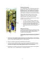
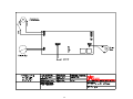
Model BO1
Bump Out 1
Model BO 2
BUMP OUT 2
Model BO 4
BUMP OUT 4
Pass-Thru Windows
TABLE OF CONTENT
Topic
Page
Disclaimer
Contact Sheet
Introduction
Product Information
Description
Safety Information
Warranty/Specifications
Dimensions
Installation Procedures
Tools needed
Materials Needed
Physical Installation
Semi Automatic Installatioin
Electrical Installation
Initial Operations and Testing
Adjustments and Calibrations
Operational Procedures
Modes of Operation
Operations
Maintenance
Maintenance Schedule
Daily
Monthly
Yearly
Service
Troubleshooting Guide (Cause and Effect)
Parts Lists
Parts List – Common To Both Models
Parts List – Model Specific
Drawings - Exploded Views / Schematics
2
3
3
4
4
5
6
7
8
8
9
13
14
16
17
19
19
20
20
20
20
21
24
25
27
DISCLAIMER
READY ACCESS DISCLAIMS ANY LIABILITY FOR ANY DAMAGE OR HARM
CAUSED TO THE BO-2 AND BO-4 DRIVE-THRU WINDOWS, IT’S OPERATOR OR
ANY OTHER EQUIPMENT HOWEVER CAUSED IF THE BO-2 DRIVE-THRU
WINDOW IS INSTALLED, REPAIRED OR SERVICED BY ANYONE OTHER THAN AN
AUTHORIZED SERVICE ENGINEER OR CONTRARY TO THE MANUFACTURERS
WRITTEN INSTRUCTION CONTAINED HEREIN.
THIS MANUAL IS INTENDED FOR USE BY THE IN-HOUSE OR AUTHORIZED FIELD
SERVICE ENGINEERS AND SALES REPRESENTATIVES
The manufacturer maintains the right to update, add or issue a new service manual at any time without
notice, thereby rendering all previous issues obsolete.
Please write the Serial Number and Installation Date for your drive-thru window in the spaces provided.
Serial Number
Date of Installation
Contact Information
For sales and service contact
Ready Access
1815 Arthur Drive
West Chicago, Illinois 60185
Email: [email protected]
Tel: 630-876-7766
Tel: 800-621-5045
Fax: 630-876-7767
Website: www.ready-access.com
3
INTRODUCTION
The Ready Access window is quality designed to give you years of reliable, trouble-free service.
Each window is shipped pre-assembled, fully glazed and ready for installation. All Ready
Access windows are thoroughly tested prior to shipping.
The original Ready Access Bump-Out window design is recognized throughout the world as the
industry standard with more units installed than any other window of its type. By design, this
ruggedly constructed unit combines functional superiority and practicality - all in an attractive
window that can match virtually any building exterior.
The BO-2 and BO-4 come in two versions, semi-automatic and electric. The electric version is
fully automatic with a manual override in case of a power outage. The doors will open and close
by stepping into an out of the light beam sensor. Electric and Semi-Automatic models meet
health department requirements for self-closing units.
PRODUCT INFORMATION
•
•
Small 12”W x 18”H Service Opening (BO-1)
Large 19"W x 18"H Service Opening (BO-2)
This large service opening is perfect for virtually any size order, from pizza to ribs to
beverage cartons.
•
Huge 19"W x 32"H Service Opening (BO-4)
This large service opening makes the Bump-Out 4 ideal for the bulkiest of orders.
•
Frame Size
Standard window dimensions are 27 3/4"W x 48 3/4"H.
•
Panoramic View
The classic Ready Access Bump-out design promotes visibility and personal contact by
offering a three sided, 180-degree view of cars and customers.
•
Quality Construction
Anodized aluminum extrusions, stainless steel and 1/4" tempered glass combine to give
you an attractive window that not only enhances building exteriors, but will not rust, pit or
weather. Track free bottom sill provides for a contaminant free surface.
•
Fully Assembled, Ready to Install
Ready Access windows are shipped completely pre-assembled, and fully glazed for
lower installation costs. Normal installation takes less than two hours.
•
Three to Five Day Shipping
Ready Access will ship any standard window order in 3 to 5 days from receipt of order.
•
Warranty and Service Support
Your Bump-Out 1, Bump-Out 2 and Bump-Out 4 come with a one year limited warranty
on parts and labor. In addition, each unit is backed by a worldwide service organization.
4
MANUAL, SEMI-AUTOMATIC OR FULLY-AUTOMATIC SERVICE OPENINGS
•
Manual – BO1 only You open and close by hand.
•
Semi- Automatic – BO-1, BO-2 and BO-4
In a Semi-Automatic operation, simply release the top lock and push on the “Push Pad”
to open the door. Both doors part from the center and easily open. A retrofit kit is
available to convert manual models into fully automatic units.
•
Fully Automatic – BO-2 and BO-4 only
The operator simply steps into an electronic light beam that opens the door panels
automatically. The door panels automatically close when the operator steps away from
the electronic light beam.
AVAILABLE OPTIONS
•
The Bump-Out 1, Bump-Out 2 and Bump-Out 4 are available in statuary bronze or clear
anodized aluminum.
•
Tinted glass is available upon request.
•
Powder coat painting is available in a wide range of custom colors.
Safety Information
WARNING: To avoid the risk of fire, Electric Shock or injury to persons, observe the following:
1. Before servicing or cleaning the unit, switch the power off at the mechanical switch near the unit
(Installed by an Electrician) or the electrical entry service panel/circuit breaker. (Load Center)
• OSHA LOCK OUT – TAG OUT procedures are to be observed to prevent power from being
switched on accidentally.
2. Any Installation and / or Electrical work must be done by QUALIFIED persons in accordance with
all applicable codes / standards and manufacturers recommendations and specifications.
3. DO NOT insert fingers and / or foreign objects into the Drive-Thru Window.
DO NOT block or tamper with the unit in any manner while it is in operation.
4. This product must not be used in Potentially Dangerous locations such as Flammable, Explosive
Chemical – laden environment.
5
WARRANTY:
Ready Access will only accept responsibility for manufacturing defects in the
product’s construction and/or materials.
Adjustments required during installation are the responsibility of the installer or
contractor and will not be covered under warranty.
Problems caused by improper installation are the responsibility of the installer or
contractor and will not be covered under warranty.
SPECIFICATIONS AND PERFORMANCE
Fully-Automatic
Model
Number
USA
Unit
Voltage
International
Actual
Unit
Amps
Dimensions
In Inches
WxHxD
Weight
In Shipping
Carton
BO-2 - E
110/120 VAC
60Hz
220/240 VAC
50/60Hz
15 A (US)
8 A (Int’l)
27 ¾” x 48¾ x 15 ¾
156 lbs
BO-4 - E
110/120 VAC
60Hz
220/240 VAC
50/60Hz
15 A (US)
8 A (Int’l)
27 ¾” x 48¾ x 15 ¾
156 lbs
Dimensions
6
273 4"
[705.13mm]
483 4"
[1238.74mm]
BO-1
SERVICE OPENING
12" W x 18" H
153 4"
[400.21mm]
273 4"
[703.84mm]
483 4"
[1238.74mm]
BO-2
SERVICE OPENING
19" W x 18" H
153 4"
[400.21mm]
273 4"
[705.13mm]
BO-4
SERVICE OPENING
19" W x 32" H
483 4"
[1238.74mm]
153 4"
[400.21mm]
Figure 1
7
Installation Procedures
Tools required to perform the installation
•
Electric Drill
•
•
Metal Drill bits –
•
⅛” (3mm)
¼” (6mm)
½” (13mm)
1” (25mm)
•
Screwdrivers – Slotted and Phillips
•
Hacksaw
•
Jack / Utility Knife
•
Flat File – Coarse
•
Caulking gun
•
¼” Nut Driver
Extension Cord
Masonry drill bit –
¼” (6mm)
1” (25mm)
1½” (38mm)
•
Masonry Hole Saw – 1” (25mm)
•
Channel Lock Pliers
•
Tape Measurer
•
Wire Cutter
•
Step Ladder
•
Level
Materials required for installation
•
Window framing, architect specified and installed in building.
(Ready Access recommended material is ⅛“ (3mm) x 1 ¾” (44.5mm) x 4” (102mm) hollow
aluminum tubing or glazing channel)
•
Electrical Tape
•
Wire Nuts
•
Caulking – silicone (Color specific to the color of window)
•
Connectors for conduit as required
•
Shingle type shims – as required to level and plum the window
8
Physical Installation
Before you begin installing your Ready Access Drive-Thru Window, you must determine what type of installation
will be required. Wood Frame, Masonry Framing, etc.
Please refer to the details below to pick which one bests fits your application.
WARNING:
TWO PEOPLE ARE REQUIRED FOR THE LIFTING AND INSTALLATION OF THE WINDOW.
NOTE: There are two wall-mounting applications. The mounting space can be surrounded either by
sidelights (windows) or masonry. The illustrations below will show both configurations. (Figure 2)
Figure 2
PICTURED BO-4
9
1.
Confirm that the customer-supplied frame is made to accommodate the dimensions as illustrated
on page 6.
2.
Confirm that AC power has been run and is ready for connection to the window.
3.
Check shipping carton for any shipping damage and remove window from the carton.
4.
Check window for any shipping damage.
5.
Once the application has been determined, check the daylight opening of the frame being used.
The opening dimensions should be 24 ¼” wide x 34 ½” high.
6.
For a Fully-Automatic installation, check for the electrical hook-up. The AC electric should be
installed directly from the breaker box (Load Center) to the window opening before the
installation of the window.
7.
Using the paper mounting template, drill a quantity of 10, ¼” diameter pilot holes for mounting. (See
Figure 3) OUTSIDE ONLY – DO NOT DRILL THROUGH THE FRAME.
Figure 3
8.
Remove the template and drill 10, ½” hole using the ¼” pilot holes.
OUTSIDE ONLY – DO NOT DRILL THROUGHT THE FRAME.
10
9.
For Semi-Automatic installations, Drill a 1” hole through the wall as illustrated in Figure 4.
(The dimensions shown are from the inside of the building.)
12.25
(308mm)
Figure 4
10.
For Fully-Automatic, Drill a 1 ½” hole through the wall as illustrated in Figure 4.
(The dimensions shown are from the inside of the building.)
ROUGH OPENING IS SHOWN FROM
THE INSIDE LOOKING OUT
2.50
(63.5mm)
DIMENSIONS ARE TAKEN FROM THE
INSIDE DAYLIGHT OPENING OF THE
FRAME
20.25
(514.4mm)
Figure 5
11
11. Requiring 2 people, remove Ready Access Window from carton and place on top of carton lid to
prevent scratching.
12. Person number 1 should remove the bottom cover from the window and organize the mounting
hardware.
Person number 2 should apply a bead of caulk to the outside surface of the building window frame.
(Reference 1/2" drilled holes for mounting window.)
13. Requiring 2 people, stand window upright. With one person on each side of the window, lift the
window into position, aligning the counter top with the building frame sill.
With one person holding the front of the window from falling forward, the other person from the
inside will start inserting 5 of the well nuts with the washers and bolts through the inside top of the
window into the building frame. (Figure 6)
(If mounting through wood, use lag bolts. If mounting to masonry, use mason anchors)
Figure 6
From the outside, insert the remaining 4 well nuts and fasten with the bolts and washers provided,
through the bottom, underneath the counter, into the building frame.
Figure 7
12
14. DO NOT TIGHTEN - Shim unit to be square and plum. Once this has been done, tighten mounting
hardware.
15. When the window is fully secured, seal the outside of the window to the frame or building using
silicone caulk.
Semi Automatic Instructions
Push Pad Assembly
1. Mount the guide block retainer to the interior side of the wall. (Figure 8)
2. From the inside, slide the push-pad assembly through the guide block into the bottom of the
window. (Figure 9)
3. From the outside, underneath the window attach the push-pad shaft to the slide rider with the
clevis pin and hitch pin. (Figure 10)
4. Test the unit by pushing on the push-pad. Secure the cover to the outside of the window.
13
Fully-Automatic Instructions (BO2 & BO4 Only)
Electrical Installation
All power must be connected and wired by a qualified electrician and must be in compliance with all
state and local codes.
The incoming AC power line must be connected to the receptacle located underneath the counter top.
(Per Standard electrical code.) The green “grounding” wire is to be attached to the frame of the unit.
WARNING: Use only 110/120VAC – 60Hz source with a dedicated 15Amp circuit.
International power: 220/240VAC – 50/60Hz with a dedicated 8amp branch circuit.
WARNING: This must be a dedicated circuit. Other electrical equipment must not share the same
line from the 15Amp circuit breaker.
WARNING: Turning off the front panel rocker switches does not remove the 110/120 volts of electrical
power form the unit
WARNING: To disconnect the power completely from this unit, turn OFF the mechanical switch near the
unit (Installed by an Electrician) or the electrical entry service panel/circuit breaker panel
(Load Center) for this unit.
• OSHA LOCK OUT – TAG OUT procedures are to be observed to prevent power from
being switched on accidentally.
1.
2.
Remove the screws holding on the front cover.
Wire the AC source line to the receptacle located underneath the window countertop.
(See Figure 11)
Receptacle
Figure 11
14
Mounting Electric Eye Housing
1. Position eye housing on the interior wall covering the 1-1/2" hole drilled through for electric cable
passage way.
2. Align the wall mounting brackets on inside finished wall. Use as a template to scribe holes for drilling
1/4" holes for plastic mounting anchors
3. Drill 4 - ¼” (6.5mm) holes using the masonry drill bit.
4. Insert the plastic anchors and mount the brackets with the #10 or #12 screws.
5. Attach electric eye mounting channel to the wall mounting brackets with the (4) 8-32 x 1/2" screws
provided
6. Attach the sensor to the brackets and secure.
7. Take electric eye cable and pass through 1" hole into the bottom of the window unit and connect to
the cable marked "ELEC.EYE".
8. Assemble plastic electric eye housings to the electric eye mounting channel.
Inside wall pictured for
the purpose of
illustration only.
Not a part of the unit.
Figure 12
9. Turn “ON” the power to the unit. (Load center circuit breaker and power switch on the “Control unit”.
10. Test window operations. See “Testing Procedures”.
15
Initial Window Operation
Testing Procedures
Semi Automatic Operations
Action
Press your hip against the push-pad cushion and push
into the window.
Reaction
The doors will open
When you step away from the push-pad
The doors will self-close and the push-pad will extend
back into position.
Fully - Automatic Operations (Electric)
Action
Reaction
Turn the power “OFF” at the rocker switch
located on the controller unit.
Manually open and close the doors several times.
When the doors are opening, the “MOTOR RUN”
lamp will illuminate green. When the doors are
closing, “MOTOR RUN” lamp will illuminate red.
The “POWER” lamp must illuminate during both
operations. If neither of these lamps illuminate
during any of the processes, proceed to the
“Troubleshooting” section.
Turn the power “ON” at the rocker switch located
on the controller unit.
Break the electric eye beam to open the door.
The doors will open to an 18” (457.2mm) opening.
With the power “ON” break the electric eye beam
momentarily to open and close the doors.
The doors will open. They will remain in the open
position for either approximately 3.0 seconds
before closing
NOTE: The DC-3 PCB allows for longer close
delay times
(See the Adjustments and Calibration Section)
With the power “ON” break the electric eye beam
momentarily to open and close the doors. Insert
an object at least 4” (101.6mm) wide between the
doors as they are closing.
The doors will automatically reverse their action
(the doors will open), when an object is caught
between or restricting the closing of the doors.
16
Adjustments and Calibrations
Calibration:
The only calibration available on the DC-3 PC board is setting the close delay timer using the dipswitch
package mounted near the ribbon cable connector.
The CLOSE DELAY TIMER is default set at 3 seconds
AA100
CONNECTION
Follow the Chart Below for Changing
the Close Delay Time Settings
Dip Switch Settings
Time in
Switch Position
Seconds
1
2
3
4
ON
1
OFF
OFF
OFF
ON
2
OFF
OFF
OFF
ON
3
OFF OFF
OFF
ON
4
OFF OFF
OFF
5
OFF OFF
OFF
OFF
ON
ON
OFF
OFF
12
ON
ON
13
OFF
OFF
ON
ON
14
OFF
OFF
ON
15
OFF
OFF
OFF
ON
ON
23
OFF
OFF
ON
ON
24
OFF
OFF
ON
25
OFF
OFF
OFF
ON
ON
34
OFF OFF
ON
35
OFF OFF
OFF
ON
45
OFF OFF
OFF
SOLENOID
CONNECTION
MOTOR
CONNECTION
CLOSE DELAY
TIMER
MICRO-SWITCH
CONNECTION
SENSOR
CONNECTION
5
OFF
OFF
OFF
OFF
ON
OFF
OFF
OFF
ON
OFF
OFF
ON
OFF
ON
ON
The DC-2 PCB has two potentiometers
The Window Select Dial is used to set the type of door
configuration for the model of window.
Window Select
Choose settings by window style
Current Adjustment
Adjusts the power to the motor.
The Current Dial is used to increase or decrease the
power to the motor. This is adjusted to insure proper
operation.
17
Preliminary Information:
The P1 potentiometer (Pot) is used to adjust the point of
detection of the motor current. When the motor current
detection occurs, the “Current Detect” lamp on the front
panel will illuminate. If the “Close Detect” is lit when the
“Current Detect” lamp turns on, the closing of the doors
will be halted and the doors will auto-reverse and re-open.
Properly adjusting the pot allows the doors to close
completely and shuts off the power to the motor the
moment the doors make contact with each other.
If improperly set, the doors will respond in one of the two
separate and distinctive manors.
P1
1. If the pot is set too far clockwise, the doors will
close and come together completely. The motor
will continue to run for about a second or two after.
2. If the pot is set too far counter-clockwise, the
doors will start to close. Stop anywhere from 2 to 6
inches apart then auto reverse and reopen the
door.
Adjustment Procedure:
The adjustment procedure begins by carefully turning the
pot to the stop position in the full clockwise position. Then
turn the pot in a counter clockwise direction until the
screwdriver slot is about halfway.
Turn the power “ON” and break the beam. The window will
probably operate properly. Continue the adjustments as
follows.
1. Continue to cycle the window and with each opening, turn the pot clockwise in small increments
until the doors come together completely while closing and the motor continues to run for about a
half of a second. (MAKE A MENTAL NOTE OF THIS POSITION.)
2. Return the screwdriver slot back to the approximate halfway position.
3. Continue to cycle the window and with each opening, turn the pot counter-clockwise in small
increments until the doors start to close and then stop anywhere from 2 to 6 inches apart then
auto reverse and reopen the door. (MAKE A MENTAL NOTE OF THIS POSITION.)
4. Now position the screwdriver slot to a position approximately halfway between the two positions
noted in steps 1 and 3. The potentiometer is now properly adjusted.
18
Operation Procedures
Modes of Operation:
The BO-1 is Manual and Semi-Automatic, the BO-2 and BO-4 windows have two modes of operation,
Semi-Automatic and Automatic.
Semi-Automatic Operations
Press your hip against the push-pad cushion and push into the window. The doors will open.
When you step away from the push-pad, the doors will self-close and extend the push-pad back
into position.
Fully-Automatic Operations
The Manual Mode is reached by turning “OFF” the main power to the window. The opening and closing
of the window is done by hand (DO NOT OPEN OR CLOSE THE DOORS WITH ANY UNDUE FORCE)
The Automatic Mode is reached by turning “ON” the main power to the window. Stepping in and out of
the sensor’s range opens and closes the doors.
Operations
After installation of the Bump-Out model Semi-Automatic or Electric Sliding window, completion of the
testing procedures and the installation of the decorative covers, the window is ready for normal use
Semi – Automatic
1. Using your hip. Lean in on the orange push pad. And then step aside.
2. The doors should open and close smoothly.
3. If the doors do not operate correctly, go to the troubleshooting guide in this manual. If the doors
still do not operate properly, then call Ready Access at
1-800-621-5045
Electric (Fully – Automatic)
1. On the controller unit, turn the power rocker switch to the “ON” position.
2. Check that the red portion of the rocker switch is visible and that the red power lamp is
illuminated
3. Break the electronic eye beam or step into the sensor beam path.
4. Step out of the beam path and wait 3 to 6 seconds for the doors to close.
5. If the doors do not operate correctly, go to the troubleshooting guide in this manual. If the doors
still do not operate properly, then call Ready Access at
1-800-621-5045
NOTE: Turn the power off to the window to prevent any damage to the PCB.
Each operator must read the operations manual before operating the unit.
19
Maintenance
Maintenance Schedule
Scheduled maintenance should be performed on a regular basis. This is to assure proper operation and
performance of the Bump-Out windows.
Daily
•
Check the sill for foreign materials and/or syrup. (Anything that might cause the window to bind
up and not operate smoothly.)
Monthly
Follow safety procedures before opening the unit.
•
Check the interior of the unit for any build up of any foreign materials using a dry cloth.
NOTE: KEEP ANY LIQUIDS OFF THE INTERIOR COMPONENTS.
• Clean moving parts and lubricate with silicone or Teflon spray.
NOTE: DO NOT LUBRICATE THE DRIVE SHAFT OR LINEAR ACTUATOR.
NOTE: Do NOT use Grease or Oils. Do NOT lubricate the motor clutch assembly.
NOTE: DO NOT LUBRICATE THE DRIVE SHAFT OR LINEAR ACTUATOR.
Semi Annual (6 Months)
• Check the front cover and side panels to ensure that they are not rubbing on the moving
mechanism.
• Check the lock bar and door locks. Inspect for missing parts and smooth operations
• Lubricate the locks with silicone.
• Inspect the hinges and bushings for any wear or damage.
• Inspect the weather stripping around the doors for wear or damage.
• Check the setscrews on the locking plate to ensure that they are tight and properly aligned with
the locking plate.
• Inspect all the bolts on the slide to make sure that they are in place.
• Check all the “Tru-arc” retaining rings to make sure that they are in place.
• Lubricate all the linkage and pivot points with silicone.
Yearly
• Have a service technician come in and perform a maintenance check on the unit.
IF NEEDED, CONTACT YOUR READY ACCESS SERVICE AGENT FOR SERVICE.
20
SERVICE
Troubleshooting Guide
Semi Automatic
Issue
Probable Cause
•
Broken Hinge
•
Replace Hinge
•
Tru-Arc retaining ring popped off
•
Check for missing or broken
Tru-Arc Ring
•
Reattach or replace the ring
•
Check for a missing or
broken clevis or hinge pin
•
Reattach or replace the pin
Roller bearing on the top of the
doors broken or fell off
•
Check the roller bearing
•
Repair or replace
•
Door hinges are no longer square
•
Repair or replace the hinges
•
Unit may have been hit by a car
•
Inspect the counter top
•
Replace if damaged
•
Check for the shoulder
screws being in place
•
Repair or replace as needed
•
Check for mounting
hardware
•
Reattach or replace the pullback spring
•
Adjust the screw on the end
of the closer
•
Replace if needed
The doors do not open.
•
Only one door opens
and the other door goes
in the opposite direction.
Door binds when trying
to open.
Doors hang loose.
Doors do not close.
Doors slam shut.
Resolution
•
•
•
•
Push Pad assembly not
connected
Shoulder screws have come
loose and fallen off the hinges
The pull back spring has come
loose or broke
Pneumatic closer worn out
21
SERVICE
Troubleshooting Guide
Fully Automatic
Issue
When the beam is
broken, the doors do not
open.
Only one door opens
and the other door goes
in the opposite direction.
Door binds when trying
to open.
Doors hang loose.
Probable Cause
Resolution
•
Defective motor assembly
•
Replace the motor assembly
•
Dirty drive shaft
•
Clean the drive shaft. It must be
free from dirt and lubricants
•
Broken Hinge
•
Replace Hinge
Tru-Arc retaining ring popped off
•
•
Check for missing or broken
Tru-Arc Ring.
•
Reattach or replace the ring
•
Clean shaft and adjust tension
from the block
•
Linear actuator is slipping
•
Dirty or defective electric eye
Dirt or other material is blocking
eye
Clean the dirt off the eye and
reflector
Defective electric eye
Replace the electric eye
•
Defective PCB Assembly
•
Replace the PCB Assembly
•
Roller bearing on the top of the doors
broken or fell off
•
Check the roller bearing
•
Repair or replace
•
Door hinges are no longer square
•
Repair or replace the hinges
•
Unit may have been hit by a car
•
Inspect the counter top
•
Replace if damaged
•
Check for the shoulder screws
being in place
•
Repair or replace as needed
•
Shoulder screws have come loose
and fallen off the hinges
Unit works intermittently.
•
Defective PCB Assembly
•
Replace the PCB Assembly
Doors open as soon as
the switch is turned
“ON”.
•
Bad connection to the electronic eye
•
Check and tighten connectors
•
Bad PCB Assembly
•
Replace PCB Assembly
22
SERVICE
Troubleshooting Guide
Fully Automatic
Issue
Power switch in the “ON”
position but the light is
not illuminated.
Probable Cause
•
Resolution
No power to the controller unit
Main Circuit breaker is defective
or not “ON”
The fuse on the power supply is
blown
Main power rocker switch is
defective
AC wiring is defective
Reset or replace the main
circuit breaker in the load
center
Replace the fuse on the
power supply
Test rocker switch with an
ohmmeter. Replace if
necessary
Check AC wiring for opens.
Replace if necessary
•
Red Lamp/s not illuminating
•
Replace the switch
•
The 4 pin power connector to the
main PCB assembly is not secure
•
Secure the connector/s to the
power supply
•
The connector/s to the rocker switch
are not secure
•
Secure the connector/s to the
rocker switch
Motor runs but the doors
will not open or close.
•
Linear actuator is slipping
•
Clean shaft and adjust tension
from the block
Doors do not close
completely.
•
There is dirt and/or lubricant on the
drive shaft or linear actuator
•
Clean the drive shaft and
actuator
•
The linear actuator is loose
•
Tighten the linear actuator
23
Parts Lists
Complete Parts List (Description/Part Number) – Common to both model windows
"J"-NUT KIT BO SERIES
Current
Previous
Part
Part
Number
Number
85078900 65078901
Current
Alignment block (aligns hinges)
20220010 N/A
Current
Angle - Reinforcement - Door
20220012 N/A
Current
Angle - Reinforcement – Door
00650228 N/A
Current
Cable - Motor
20112150 N/A
Current
Cable - Power
20112149 N/A
Current
Ceiling Tile
85077700 65077701
Current
Clevis Pin for Push Rod Assy
10300003 N/A
Current
Coupling
00651100 N/A
Current
Cover - Front - Bronze
85065801 65065801
Current
Cover - Front - Clear
85065802 65065802
Current
Door Handle (order in eachs)
95064401 65064401
Current
Drive Shaft Kit BO-1,2,4 E
85104100 65104101
Current
Electric Eye Assy - BO-1,2,4
85040000 65240001
Current
Electric Eye/Reflector Kit
85000200 00651144
Current
Eye Switch Retrofit
84000300 N/A
Current
Center Stop - Door BO-2 L/O
85079100 65079101
Current
Hitch Pin Clip for Push Rod Assy
10300004 N/A
Current
Latch Spring
00650269 N/A
Current
Linear Actuator Kit
85000500 20110043
Current
Linkage - Straight
95062200 65062201
Current
Linkage Nyliner & Retaining Ring
85000400 N/A
Current
Linkage Pan Assy – BO-2
85098000 65098001
Current
Linkage Pan Assy – BO-4
85098500 N/A
Current
Linkage Plate Assy (Triangle Shape)
95061800 65061801
Current
Lock - Top (1 each) SMALL Doors
85088200 65088201
Current
Lock Bar - Bottom - Bronze
85078301 65078301
Current
Lock Bar - Bottom - Clear
85078302 65078302
Current
Lock Bar – Bottom Powder Painted
85078303 N/A
Current
Mtg Hardware Kit
10706201 N/A
Current
Nylon Guide Block - Rod Assy
50020018 N/A
Current
Offset Linkage
95062100 65062101
Current
Locking Plate
95061900 65061901
Current
Motor DC - After 8/99
20110245 N/A
Current
MOTOR REPAIR KIT BO-1,2,4 E
85138700 65138701
Current
Pan Slide Sub Assy - BO-2,4
85097800 65097801
Current
Description
24
Status
Note
(Hinge-Large)
Waist level operation
Panel - L/H - Bronze BO-1,2,4
Current
Previous
Part
Part
Number
Number
85065601 65065601
Current
Panel - R/H - Bronze BO-1,2,4
85065602 65065602
Current
PC Board - DC3 as of 12/14/01
Call for #
Current
Pivot block - Door Frame
20220040 N/A
Current
Pivot Bracket for Door Closer
65063101 N/A
Current
Pivot Support for Door Closer
65063201 N/A
Current
Plastic Switch Hsg - After 5/95
65199901 N/A
Current
Pneumatic Closer
85134100 65134101
Current
Power Supply Int'l , BO1,2,4,275 Int'l
Call for #
N/A
Current
Provide Serial #
Power Supply, BO-1,2,4, 275
Call for #
N/A
Current
Provide Serial #
POWER SWITCH - BO-1, BO-2, BO-4 85002800 N/A
Current
Push Pad SEMI AUTO
85077900 65077901
Current
Push Rod Assy - 16" LG / BO-1,2,4
85078016 65078001
Current
Push Rod Assy - 22" LG / BO-1,2,4
85078022 65078022
Current
Push Rod Assy - 30" LG / BO-1,2,4
85078030 65078030
Current
Push Rod Assy - 38" LG / BO-1,2,4
85078038 65078038
Current
Retainer Bottom Lock Bar
65024001 N/A
Current
Retro Fit Kit - BO-2,4
84000800 N/A
Current
SEMI TO ELEC. 220V
Retro Fit Kit - Semi to Auto
84000100 N/A
Current
Semi to Electric DC - DC
Power as of 1/26/00
Includes PC Board
Rivet
10180009 N/A
Current
Rocker Switch for PCBA Cover
20110214 N/A
Current
Description
Status
Rollers - Top Track (2 doors w/blocks) 85089300 65089301
Current
Rubber Glass Channel
65028601 N/A
Current
Screw
10010061 N/A
Current
Screw for inside cover, sensor striker
10010114 N/A
Current
Screw for Top Block
10010154 N/A
Current
Screw Kit - Shoulder Screw - BO-2,4
85103800 65103801
Current
Screws w/lock washers for roller
blocks
Set Screw for Locking Plate
10010107 N/A
Current
10040004 N/A
Current
Shoulder Screw for Manual Release
10010204 N/A
Current
Spacer Door Hinge
20200062 N/A
Current
Spring & Ball Knob Kit (3 ea. kit)
85000300 00650284
Current
Spring - Extension (for top track)
20060017 N/A
Current
Spring Kit - Extension - BO-2,4
85103700 65103701
Current
Spring Mtg Angle
65064001 N/A
Current
Stop Full Open Window (Blk Neop)
65073301 N/A
Current
Striker Angle - Top Lock
65023701 N/A
Current
Top Track Kit BO-2,4
85073800 65073801
Current
Weather Strip Kit - BO-2,4,10, 275
85104000 65104001
Current
25
Note
Provide Serial #
8/99 BO1,2,4 after 2/27/02
Model Specific Parts ( BO-2)
Door Assy - L/H - Bronze - BO-2
Current
Previous
Part
Part
Number
Number
85078701 65078701
Current
Door Assy - L/H - Clear- BO-2
85078703 65078703
Current
Door Assy - R/H - Bronze - BO-2
85078702 65078702
Current
Door Assy - R/H - Clear - BO-2
85078704 65078704
Current
Hinge bushing - Bronze
20010008 N/A
Current
Hinge Cover - Bronze
85058401 65058401
Current
Hinge Cover - Clear (BO-2)
85058402 65058402
Current
Hinge w/lock Plate BO-2
85094500 65094501
Current
Mounting Block - Upper Hinge 65108001 20220011
Bronze
Mounting Block - Upper Hinge - Clear 65108002 20220011
Current
Upper Hinge Bearing (Door Guide)
Current
Description
00651271 N/A
Status
Note
Current
Model Specific Parts ( BO-4)
Door Assy - L/H - Bronze - BO-2
Current
Previous
Part
Part
Number
Number
85078701 65078701
Current
Door Assy - L/H - Clear- BO-2
85078703 65078703
Current
Door Assy - R/H - Bronze - BO-2
85078702 65078702
Current
Door Assy - R/H - Clear - BO-2
85078704 65078704
Current
Hinge bushing- Bronze
20220016 N/A
Current
Hinge Cover - Bronze
85058401 65058401
Current
Hinge Cover - Clear (BO-2)
85058402 65058402
Current
Hinge w/lock Plate BO-2
85094500 65094501
Current
Mounting Block - Upper Hinge 65108001 20220011
Bronze
Mounting Block - Upper Hinge - Clear 65108002 20220011
Current
Upper Hinge Bearing (Door Guide)
Current
Description
00651271 N/A
26
Status
Current
Note
Drawings
Exploded Views
Page
Part Number
If Applicable
Description
28
N/A
Frame – Exploded View
29
N/A
Door Assembly – Exploded View
30
85098000
Pan and Linkage Assembly BO-2 – Exploded View
30
85098500
Pan and Linkage Assembly BO-4 – Exploded View
31
N/A
Semi Automatic – Exploded View
32
N/A
Fully Automatic – Exploded View
33
N/A
Component layout - Photo
Schematics
Page
Part Number
If Applicable
Description
34
N/A
Pre – DC-3 PCB Assembly - Electrical Schematic
35
N/A
DC-3 PCB Assembly - Wiring Layout
36
N/A
Electric Eye Wiring
27
REF
ID #
1
PART
NUMBER
85065601
DESCRIPTION
Panel L/H BRZ
REF
ID #
3
PART
NUMBER
85065801
DESCRIPTION
Panel Front BRZ
1
85065701
Panel L/H CLR
3
85065802
Panel Front CLR
2
85065602
Panel R/H BRZ
4
85077700
Ceiling Tile
2
85065702
Panel R/H CLR
Model Specific Parts
BO-2
BO-4
5
85058401
Hinge Cover BRZ
5
N/A
Hinge Cover BRZ
5
85058402
Hinge Cover CLR
5
N/A
Hinge Cover CLR
28
REF
ID #
1
PART
NUMBER
85078301
DESCRIPTION
Lock Bar Assy BR
REF
ID #
6
PART
NUMBER
85103800
1
85078302
Lock Bar Assy CL
7
85088200
DESCRIPTION
Shoulder Screw Kit
(4 Screws / 4 blocks)
Top Lock Assembly
4
5
85073800
85089300
Top Track Assembly
Roller – Top Track
12
95064401
Handle
Model Specific Parts
BO-2
2
9
8
85094500
20200062
20010008
11
11
13
14
14
85078701
85078703
85079100
85078702
85078704
BO-4
Hinge Assembly
Hinge Spacer
Upper/ Lower Hinge
Bearing
Door Assy L/H BRZ
Door Assy L/H CLR
Center Stop
Door Assy R/H BRZ
Door Assy R/H CLR
29
2
9
8
85067500
10230102
20010005
11
11
13
14
14
85067401
85067403
65068101
85067402
85067404
Hinge Assembly
Hinge Spacer
Upper/ Lower Hinge
Bearing
Door Assy L/H BRZ
Door Assy L/H CLR
Center Stop
Door Assy R/H BRZ
Door Assy R/H CLR
PAN AND LINKAGE ASSEMBLY
Part Number- BO-2 – 85098000
Part Number – BO-4 - 85098500
REF
ID #
PART
NUMBER
DESCRIPTION
REF
ID #
1
95061900
BO-2 Locking Plate Assembly
5
1
95069000
BO-4 Locking Plate Assembly
6
2
95062200
Straight Linkage
3
85097800
Slide Sub-Assembly
4
95062000
Linkage Mounting Plate
PART
NUMBER
DESCRIPTION
**
85000400
Nylon Sleeve Bearing
Tru-Arc Retaining Ring
7
95062100
Offset Linkage
8
95061800
Linkage Plate
** Order – Bearing / Linkage Nyliner Retaining Ring Kit # 85000400
30
REF
ID #
PART
NUMBER
DESCRIPTION
REF
ID #
PART
NUMBER
DESCRIPTION
1
85098000
Pan and Linkage Assembly – BO-2
4
85134100
Pneumatic Closer
1
85098500
Pan and Linkage Assembly – BO-4
5
65063101
Closer Pivot Bracket
2
85103700
Extension (Pull Back) Spring
6
65063201
Closer Pivot Support
3
65064001
Spring Mount Angle
31
REF
ID #
PART
NUMBER
REF
ID #
DESCRIPTION
1
85098000
Pan & Linkage Assembly – BO-2
1
85098500
Pan & Linkage Assembly – BO-4
3
85000500
Linear Actuator
4
85104100
Drive Shaft
PART
NUMBER
**
5
6&7
20110254
**
** Order – Motor Interim Repair Kit # 85138700
32
DESCRIPTION
Coupling
Motor (Only DC available)
Flexible Motor Mount & Bracket
Duplex
Receptacle
Drive Shaft
Motor
Linear Actuator
Component Placement
33
PCB Assembly
Power Supply
34
35
ELECTRIC EYE
SENSOR
BLUE
BLACK
BROWN
BLUE
BLACK
BROWN
PINK
PINK
PINK & BLUE CONNECTED
TOGETHER WITH RED WIRE
ELECTRIC EYE
SENSOR
PINK
BLUE
BLACK
BROWN
USED IN PRODUCTS:
RED
WHITE
BLACK
DESIGN BY:
MATERIAL: OMRON ELECTRIC EYE
SC
WORK TO DIMENSIONS-DO NOT SCALE
TOL. UNLESS SPECIFIED
XXXX TOL. NOT REQ'D
TOL. CLASS
± .030
ANGULAR TOL.
± 1°
WAIST HIGH BEAM BREAK
DATE: 11/08/05
MATERIAL SPEC:
R
REVISION:
OR
REVISION DATE:
DRAWN BY:
11/8/05
LATEST REVISION NOT
SC
GAUGE:
DATE: 11/08/05
1815 Arthur Drive West Chicago, IL
800-621-5045 630-876-7766 Fax 63
DESCRIPTION:
E:
ELECTRIC EYE
PART. NO.:
36
WIRING DIAGRAM
0-876-7767
37
38
39
Ready Access, 1815 Arthur Drive, West Chicago, Illinois 60185, Tel: 630-876-7766, Tel: 800-621-5045
Fax: 630-876-7767, Email: [email protected], Website: www.ready-access.com
40
BO-1, 2, 4 INSTALLATION SERVICE OPERATIONS MANUAL 11_19_08