1
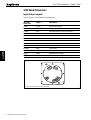
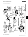
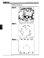
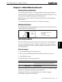
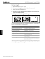
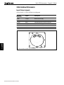
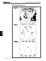
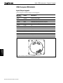
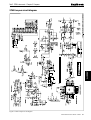
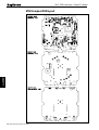
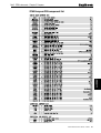
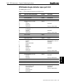
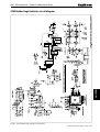
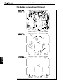
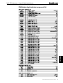
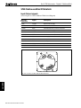
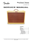
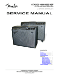
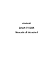
Part 2. ST60 Instruments – Analogue
Part 2. ST60 Analogue instruments
D4468-3
ST60 Instruments Service Manual 83142-1 i
Part 2. ST60 Instruments – Analogue
Contents
ST60 Analogue instrument exploded view ........................................................................ iv
Chapter 1. ST60 Wind instrument .................................................................................... 1
Disassembly/reassembly ............................................................................................ 1
PCB identification ...................................................................................................... 1
Self-test procedure ...................................................................................................... 1
Self-test stage 1 ................................................................................................. 1
Self-test stage 2 ................................................................................................. 2
Self-test stage 3 ................................................................................................. 2
Self-test stage 4 ................................................................................................. 3
Useful PCB test points ................................................................................................ 4
ST60 Wind spare parts list ........................................................................................... 5
ST60 Wind PCB details .............................................................................................. 6
Input/Output signals .......................................................................................... 6
ST60 Wind circuit diagram ................................................................................ 7
ST60 Wind PCB layout............................................................................................... 8
ST60 Wind PCB component list ........................................................................ 9
Chapter 2. ST60 CH Wind instrument............................................................................ 11
Disassembly/reassembly .......................................................................................... 11
PCB identification .................................................................................................... 11
Self-test procedure .................................................................................................... 11
Self-test stage 1 ............................................................................................... 11
Self-test stage 2 ............................................................................................... 12
Self-test stage 3 ............................................................................................... 13
Useful PCB test points .............................................................................................. 13
ST60 CH Wind spare parts list ................................................................................... 15
ST60 CH Wind PCB details ...................................................................................... 16
Input/Output signals ........................................................................................ 16
ST60 CH Wind circuit diagram ........................................................................ 17
ST60 CH Wind PCB layout ...................................................................................... 18
ST60 CH Wind PCB component list ................................................................ 19
Chapter 3. ST60 Compass instrument ............................................................................ 21
Disassembly/reassembly .......................................................................................... 21
PCB identification .................................................................................................... 21
Self-test procedure .................................................................................................... 21
Self-test stage 1 ............................................................................................... 21
Self-test stage 2 ............................................................................................... 22
Self-test stage 3 ............................................................................................... 22
Self-test stage 4 ............................................................................................... 23
ii ST60 Instruments Service Manual 83142-1
Part 2. ST60 Instruments – Analogue
Useful PCB test points .............................................................................................. 23
ST60 Compass spare parts list ................................................................................... 25
ST60 Compass PCB details ...................................................................................... 26
Input/Output signals ........................................................................................ 26
ST60 Compass circuit diagram ........................................................................ 27
ST60 Compass PCB layout ....................................................................................... 28
ST60 Compass PCB component list ................................................................. 29
Chapter 4. ST60 Rudder Angle Indicator instrument ..................................................... 31
Disassembly/reassembly .......................................................................................... 31
PCB identification .................................................................................................... 31
Self-test procedure .................................................................................................... 31
Self-test stage 1 ............................................................................................... 31
Self-test stage 2 ............................................................................................... 32
Self-test stage 3 ............................................................................................... 32
Self-test stage 4 ............................................................................................... 33
Useful PCB test points .............................................................................................. 33
ST60 Rudder Angle Indicator spare parts list .............................................................. 35
ST60 Rudder Angle Indicator PCB details ................................................................. 36
Input/Output signals ........................................................................................ 36
ST60 Rudder Angle Indicator circuit diagram ................................................... 37
ST60 Rudder Angle Indicator PCB layout .................................................................. 38
ST60 Rudder Angle Indicator component list ................................................... 39
Chapter 5. ST60 Clubhouse Wind instrument ................................................................ 41
Disassembly/reassembly .......................................................................................... 41
PCB identification .................................................................................................... 41
Self-test procedure .................................................................................................... 41
Self-test stage 1 ............................................................................................... 41
Self-test stage 2 ............................................................................................... 42
Self-test stage 3 ............................................................................................... 42
Self-test stage 4 ............................................................................................... 43
Useful PCB test points .............................................................................................. 43
ST60 Clubhouse Wind spare parts list ........................................................................ 45
ST60 Clubhouse Wind PCB details ........................................................................... 46
Input/Output signals ........................................................................................ 46
ST60 Clubhouse Wind circuit diagram ............................................................. 47
ST60 Clubhouse Wind PCB layout ............................................................................ 48
ST60 Clubhouse Wind PCB component list ..................................................... 49
ST60 Instruments Service Manual 83142-1
iii
Figure 1: ST60 Wind, CH Wind, Compass and Rudder Angle Indicator Digital Instrument exploded view
iv ST60 Instruments Service Manual 83142-1
1
18
2
Flush mounting
Assembly
2
6
3
19(x4)
Torque 0.33Nm (3lb in)
20
4
21
5
7
(Note A)
8
(Note B)
9 (Note A)
11
1. Facia bezel
2. Keypad
3. Facia
4. Inner keypad
5. Shroud
6. Pointer
7. Display label
8. LCD analogue display
9. Diffuser
10. Reflector
11. PCB assembly
17
D4449-1
12. Case seal
13. Rear case
14. Washer (x3)
15. Screw (x11)
16. Label (rear case)
17. Gasket
18. Flush mount bezel
19. Screw (x4)
20. Flush mount seal
21. Rear bracket
15 (x8)
Torque 0.22Nm(2lbin)
16
14 15 (x3)
(x3) Torque 0.22Nm(2lbin)
12 (Note C) 13
A. Display label (7) and Diffuser (9) fitted
to the Rudder Angle Indicator do not
have an LCD aperture.
B. LCD analogue display (8) is not fitted
to a Rudder Angle Indicator.
C. It is recommended that a new case
seal (12) is fitted on re-assembly.
Note:
10
Part 2. ST60 Instruments – Analogue
ST60 Analogue instrument exploded view
Part 2. ST60 Instruments –Chapter 1. Wind
Chapter 1. ST60 Wind instrument
Disassembly/reassembly
On reassembly (refer to Figure 1), it is important that the PCB assembly module is
fixed to the facia (3) using a torque of 0.22Nm (2lb in). Similarly, fixing the rear case
(13) to the facia (3) must also be torqued to 0.22Nm (2lb in).
Note: Failure to practice using the recommended torques may result in damage to
the facia inserts.
It is also recommended a new case seal (12) is fitted on reassembly.
PCB identification
WI:
CH:
CO:
RU:
Wind and Clubhouse Wind
CH Wind
Compass
Rudder Angle Indicator
D4492-1
Self-test procedure
The ST60 Wind instrument has built-in self-test functions to aid fault diagnosis.
To access self-test mode, press Key 1 and Key 4 together for 4 seconds. When the
unit beeps, immediately press Key 3 and Key 4 together momentarily. The unit will
enter self-test stage 1.
Self-test stage 1
A. The unit should display S t followed by T1.
B. There will be a SeaTalk transmission to check the transmit/receive circuits.
C. The EEPROM is tested.
The following failure codes may be generated:
Message
Failure Mode
Action
F01
SeaTalk Rx/Tx
Check for damaged bucket connectors/rear-case pins.
Check SeaTalk interface components around TR3 and TR5.
F02
EEPROM failure
Replace EEPROM (IC8)
If there is no audible beep, generated by the key presses, check around TR2 and TR6
and the buzzer for damage. If the beep is quiet, check R79.
If all tests pass, P is shown on the display. Press Key 1 and Key 2 together
momentarily to progress to self-test stage 2.
ST60 Instruments Service Manual 83142-1 1
A22005
To aid identification of PCBs an identifying component has been included in the top
left hand corner of the populated PCB.
Part 2. ST60 Instruments – Chapter 1. Wind
Self-test stage 2
A. The unit should display T2 for 1 second.
B. Illumination will change between level 0 and level 3 every second.
C. Any key press will cause audible beep.
D. The pointer will rotate continuously. This will highlight a problem if the pointer
makes contact with the dial or window.
E. LCD segments will cycle through the following sequence:
1
2
3
D4491-1
A22005
No fail codes are generated since stage 2 is an audio/visual check. The following can,
however, be used as a guide to isolate a problem:
Failure Mode
Action
Keypad Illumination failure
(Dial illumination will also be degraded).
Check TR9, TR11, R78 and R91a.
Check LEDs 1, 4, 7 and 8 for open circuit.
Keypad illumination OK
but degraded Dial illumination.
Check TR10, TR11, R75 and R91b.
Check LEDs 13 - 16 for open circuit.
No beep when key pressed.
Replace keyswitch.
LCD segment(s) missing completely.
Check LCD solder pins for poor/dry joints.
Check IC3 for unsoldered pins.
Faint LCD segments.
Check LCD pins for shorts.
Check IC3 for shorts.
Pointer not rotating or erratic movement.
Check motor winding continuity.
Approximately 150 ohms between TP135 and TP136 and
between TP142 and TP143.
When the pointer has completed at least one rotation, press Key 1 and Key 2 together
momentarily to progress to self-test stage 3.
Self-test stage 3
This stage is to set up pointer offset and corrections. On entry the LCD will show T3
and then indicate the position to which the pointer should be positioned to adjust for
pointer offset.
Momentary presses of Key 1 will rotate the pointer clockwise to align with the major
graduations.
Should there be any misalignment repeatedly press Key 3 for anti-clockwise or Key 4 for
clockwise adjustment until correct alignment is obtained on all major graduations.
On completion of correction adjustments press Key 1 and Key 2 together
momentarily to progress to self-test stage 4.
2 ST60 Instruments Service Manual 83142-1
Part 2. ST60 Instruments –Chapter 1. Wind
Self-test stage 4
Note: This stage can be completed with either a Rotavecta transducer or Windvane
transducer connected.
A. The unit should display T4.
B. Perform transducer operation as described below.
Rotavecta. Spin the rotavecta buckets. The display will show P for a pass or F5 for a
failure.
Windvane. Spin the annemometer, then turn the vane in a complete circle. The
display will show P for a pass, F3 for a failed windvane test or F4 for a failed
annemometer test.
Check
Action
Rotavecta signal:
Turn rotavecta cups and check voltage at
P13 switches between approximately
3V and 8V.
• Constant current supply at P13 present.
Check around TR1 and IC4c.
• 0V supply at P14 present.
Check L11 open circuit.
• Check ROTAPRES (IC4 pin 14) is low.
Annemometer signal:
Turn annemometer and check voltage at
P13 switches between approximately
2V and 8V.
• Check L7 and R13 for open circuit.
• 8V supply at P7.
Check L4, R84 for open circuit.
• 0V supply at P11 present.
Check L8 for open circuit.
• Check around IC4b.
Wind vane signal:
Slowly turn vane through 360°. Signal at
SIN (P8) and COS (P4) should vary between
approximately 2.2V and 5.8V.
• 8V supply at P7 present.
Check L4, R84 for open circuit.
• 0V supply at P11 present.
Check L8 for open circuit.
If the above is OK then the problem probably lies within the ADC circuit.
• Check L5,L6, R52, R82 for open circuit.
• Check ADC circuit around IC5 and IC6.
To exit self-test and store pointer corrections press Key 1 and Key 2 together for
2 seconds.
If storage of pointer corrections is not required press Key 1 and Key 2 together
momentarily to exit.
ST60 Instruments Service Manual 83142-1 3
A22005
If the test fails, check the following ensuring the transducer is connected:
Part 2. ST60 Instruments – Chapter 1. Wind
Useful PCB test points
Vcc 5V
TP10
0V
TP14
8V, transducer supply
TP80
Display illumination PWM
TP81
Key illumination PWM
TP191
SeaTalk receive
TP110
Integrator output (ADC)
TP119
ADC interupt
TP135
Motor drive Sin B
TP136
Motor drive Sin A
TP143
Motor drive Cos B
TP142
Motor drive Cos A
A22005
TP7
4 ST60 Instruments Service Manual 83142-1
Part 2. ST60 Instruments –Chapter 1. Wind
ST60 Wind spare parts list
The item numbers refer to
Figure 1: ST60 Analogue Instrument exploded view
Item
Spare/Accessory Description
Part No.
1
Facia bezel
A25001
–
Suncover, standard
A25004
Not illustrated
2
Keypad,Wind
A28015
Pack of 5
Facia with case seal, including
Facia
Case seal
Washer (x3)
Screw (x11)
A28013
3
12
14
15
Inner keypad, including
Inner keypad
Case seal
Washer (x3)
Screw (x11)
A28022
4
12
14
15
5
Shroud, Wind
A28048
6
Pointer
A28041
Pack of 5
7
Display label,Wind
A28043
Pack of 5
8
LCD, analogue display
A28025
PCB and dial assembly, Wind
including
A28004
6
7
8
9
10
11
12
14
15
Comments
See A28027
Torque to 0.22Nm (2lb in)
See A28027
Pointer
Display label, Wind
LCD, analogue display
Diffuser
Reflector
PCB assembly
Case seal
Washer (x3)
Screw (x11)
Assembled module consisting of items 6, 7, 8, 9,
10,11.
See A28041
See A28043
See A28025
See A28027
Torque to 0.22Nm (2lb in)
12
Case seal
A28027
Pack of 5
Rear case assembly, including
Case seal
Rear case
Screw (x8)
A28014
12
13
15
16
Label,Wind (rear case)
A28039
Pack of 5
17
Gasket
A28028
Pack of 5
18
Flush mount bezel
A25002
Flush mount kit, including
Suncover, flush mount
Flush mount bezel
Screw (x4)
Flush mount seal
Rear bracket
A25003
–
18
19
20
21
See A28027
Torque to 0.22Nm (2lb in)
Not illustrated
See A25002
Torque to 0.33Nm (3lb in)
ST60 Instruments Service Manual 83142-1 5
A22005
Torque to 0.22Nm (2lb in)
Part 2. ST60 Instruments – Chapter 1. Wind
ST60 Wind PCB details
Input/Output signals
Rear case
connection
Signal
Description
A (Red)
12V EXT
Nominal 12V DC supply
B (Screen)
0V EXT
OV
C (Yellow)
DATA
Intermittent streams of (nominal) 12V pulses
D (Red)
12V EXT
Nominal 12V DC supply
E (Screen)
0V EXT
OV
F (Yellow)
DATA
Intermittent streams of (nominal) 12V pulses
G (Red)
8V
Vane supply
H (Green)
SIN
sin output
J (Blue)
COS
cos output
K (Yellow)
ANN
annemometer
L (White)
SCREEN
Transducer OV return
N (Red)
ROTA+
Rotavecta current constant
P (Blue)
ROTA–
Rotavecta 0V
A
B
CD E
F
P
G
A22005
(refer to Figure 2. ST60 Wind circuit diagram)
N
M
RO
J
L K
H
TA
N
VA
Rear case connections to ST60 Wind instrument
6 ST60 Instruments Service Manual 83142-1
E
D4486-1
Part 2. ST60 Instruments –Chapter 1. Wind
A22005
D4463-1
ST60 Wind circuit diagram
Figure 2. ST60 Wind circuit diagram
ST60 Instruments Service Manual 83142-1 7
Part 2. ST60 Instruments – Chapter 1. Wind
A22005
ST60 Wind PCB layout
Taken from Drawing No: 4318-002 Issue: E Date: 26-10-98
8 ST60 Instruments Service Manual 83142-1
D4471-1
Part 2. ST60 Instruments –Chapter 1. Wind
A22005
ST60 Wind PCB component list
Taken from Drawing No: 4318-002 Issue: E Date: 26-10-98
D4472-1
ST60 Instruments Service Manual 83142-1 9
A22005
Part 2. ST60 Instruments – Chapter 1. Wind
10 ST60 Instruments Service Manual 83142-1
Part 2. ST60 Instruments – Chapter 2. CH Wind
Chapter 2. ST60 CH Wind instrument
Disassembly/reassembly
On reassembly (refer to Figure 1), it is important that the PCB assembly module is
fixed to the facia (3) using a torque of 0.22Nm (2lb in). Similarly, fixing the rear case
(13) to the facia (3) must also be torqued to 0.22Nm (2lb in).
Note: Failure to practice using the recommended torques may result in damage to
the facia inserts.
It is also recommended a new case seal (12) is fitted on reassembly.
PCB identification
To aid identification of PCBs an identifying component has been included in the top
left hand corner of the populated PCB.
WI:
CH:
CO:
RU:
Wind and Clubhouse Wind
CH Wind
Compass
Rudder Angle Indicator
D4493-1
The ST60 CH Wind instrument has built-in self-test functions to aid fault diagnosis.
To access self-test mode, press Key 1 and Key 4 together for 4 seconds. When the
unit beeps, immediately press Key 3 and Key 4 together momentarily. The unit will
enter self-test stage 1.
Self-test stage 1
A. The unit should display S t followed by T1.
B. There will be a SeaTalk transmission to check the transmit/receive circuits.
C. The EEPROM is tested.
The following failure codes may be generated:
Message
Failure Mode
Action
F01
SeaTalk Rx/Tx
Check for damaged bucket connectors/rear-case pins.
Check SeaTalk interface components around TR3 and TR5.
F02
EEPROM failure
Replace EEPROM (IC8)
If there is no audible beep, generated by the key presses, check around TR2 and TR6
and the buzzer for damage. If the beep is quiet, check R79.
If all tests pass, P is shown on the display. Press Key 1 and Key 2 together
momentarily to progress to self-test stage 2.
ST60 Instruments Service Manual 83142-1 11
A22006
Self-test procedure
Part 2. ST60 Instruments – Chapter 2. CH Wind
Self-test stage 2
A. The unit should display T2 for 1 second.
B. Illumination will change between level 0 and level 3 every second.
C. Any key press will cause audible beep.
D. The pointer will rotate continuously. This will highlight a problem if the pointer
makes contact the dial or window.
E. LCD segments will cycle through the following sequence:
1
2
3
D4491-1
A22006
No fail codes are generated since stage 2 is an audio/visual check. The following can,
however, be used as a guide to isolate a problem:
Failure Mode
Action
Keypad Illumination failure
(Dial illumination will also be degraded).
Check TR9, TR11, R78 and R91a.
Check LEDs 1, 4, 7 and 8 for open circuit.
Keypad illumination OK
but degraded Dial illumination.
Check TR10, TR11, R75 and R91b.
Check LEDs 13 - 16 for open circuit.
No beep when key pressed.
Replace keyswitch.
LCD segment(s) missing completely.
Check LCD solder pins for poor/dry joints.
Check IC3 for unsoldered pins.
Faint LCD segments.
Check LCD pins for shorts.
Check IC3 for shorts.
Pointer not rotating or erratic movement.
Check motor winding continuity.
Approximately 150 ohms between TP135 and TP136 and
between TP142 and TP143.
When the pointer has completed at least one rotation, press Key 1 and Key 2 together
momentarily to progress to self-test stage 3.
12 ST60 Instruments Service Manual 83142-1
Part 2. ST60 Instruments – Chapter 2. CH Wind
Self-test stage 3
This stage is to set up pointer offset and corrections. On entry the LCD will show T3
and then indicate the position to which the pointer should be positioned to adjust for
pointer offset.
Momentary presses of Key 1 will rotate the pointer clockwise to align with the major
graduations.
Should there be any misalignment repeatedly press Key 3 for anti-clockwise or
Key 4 for clockwise adjustment until correct alignment is obtained on all major
graduations.
On completion of correction adjustments press K1 and K2 together momentarily to
exit self-test stage 3.
The unit will display t4 for 1 second and then P for pass.
To exit self-test and store pointer corrections press Key 1 and Key 2 together for
2 seconds.
If storage of pointer corrections is not required press Key 1 and Key 2 together
momentarily to exit.
TP7
Vcc 5V
TP10
0V
TP80
Display illumination PWM
TP81
Key illumination PWM
TP191
SeaTalk receive
TP135
Motor drive Sin B
TP136
Motor drive Sin A
TP143
Motor drive Cos B
TP142
Motor drive Cos A
A22006
Useful PCB test points
ST60 Instruments Service Manual 83142-1 13
Part 2. ST60 Instruments – Chapter 2. CH Wind
A22006
This page is
intentionally
left blank
14 ST60 Instruments Service Manual 83142-1
Part 2. ST60 Instruments – Chapter 2. CH Wind
ST60 CH Wind spare parts list
The item numbers refer to
Figure 1: ST60 Analogue Instrument exploded view
Item
Spare/Accessory Description
Part No.
1
Facia bezel
A25001
–
Suncover, standard
A25004
Not illustrated
2
Keypad, CH Wind
A28015
Pack of 5
Facia with case seal, including
Facia
Case seal
Washer (x3)
Screw (x11)
A28013
3
12
14
15
Inner keypad, including
Inner keypad
Case seal
Washer (x3)
Screw (x11)
A28022
4
12
14
15
5
Shroud, CH Wind
A28049
6
Pointer
A28041
Pack of 5
7
Display label, CH Wind
A28044
Pack of 5
8
LCD, analogue display
A28025
PCB and dial assembly, CH Wind
including
A28005
See A28027
Torque to 0.22 Nm (2lb in)
See A28027
Torque to 0.22 Nm (2lb in)
Pointer
Display label, CH Wind
LCD, analogue display
Diffuser
Reflector
PCB assembly
Case seal
Washer (x3)
Screw (x11)
Assembled module consisting of items 6, 7, 8, 9,
10,11.
See A28041
See A28044
See A28025
See A28027
Torque to 0.22 Nm (2lb in)
12
Case seal
A28027
Pack of 5
Rear case assembly, including
Case seal
Rear case
Screw (x8)
A28014
12
13
15
16
Label, CH Wind (rear case)
A28040
Pack of 5
17
Gasket
A28028
Pack of 5
18
Flush mount bezel
A25002
Flush mount kit, including
Suncover, flush mount
Flush mount bezel
Screw (x4)
Flush mount seal
Rear bracket
A25003
–
18
19
20
21
See A28027
Torque to 0.22 Nm (2lb in)
Not illustrated
See A25002
Torque to 0.33 Nm (3lb in)
ST60 Instruments Service Manual 83142-1 15
A22006
6
7
8
9
10
11
12
14
15
Comments
Part 2. ST60 Instruments – Chapter 2. CH Wind
ST60 CH Wind PCB details
Input/Output signals
(refer to Figure 3. ST60 CH Wind circuit diagram)
Rear case
connection
Signal
Description
A (Red)
12V EXT
Nominal 12V DC supply
B (Screen)
0V EXT
OV
C (Yellow)
DATA
Intermittent streams of (nominal) 12V pulses
D (Red)
12V EXT
Nominal 12V DC supply
E (Screen)
0V EXT
OV
F (Yellow)
DATA
Intermittent streams of (nominal) 12V pulse
B
CD E
F
P
G
A
M
RO
J
L K
H
TA
A22006
N
N
VA
Rear case connections to ST60 CH Wind instrument
16 ST60 Instruments Service Manual 83142-1
E
D4487-1
Part 2. ST60 Instruments – Chapter 2. CH Wind
A22006
D4464-1
ST60 CH Wind circuit diagram
Figure 3. ST60 CH Wind circuit diagram
ST60 Instruments Service Manual 83142-1 17
Part 2. ST60 Instruments – Chapter 2. CH Wind
A22006
ST60 CH Wind PCB layout
Taken from Drawing No: 4319-002 Issue: E Date: 26-10-98
18 ST60 Instruments Service Manual 83142-1
D4473-1
Part 2. ST60 Instruments – Chapter 2. CH Wind
A22006
ST60 CH Wind PCB component list
Taken from Drawing No: 4319-002 Issue: E Date: 26-10-98
D4474-1
ST60 Instruments Service Manual 83142-1 19
A22006
Part 2. ST60 Instruments – Chapter 2. CH Wind
20 ST60 Instruments Service Manual 83142-1
Part 2. ST60 Instruments – Chapter 3. Compass
Chapter 3. ST60 Compass instrument
Disassembly/reassembly
On reassembly (refer to Figure1), it is important that the PCB assembly module is
fixed to the facia (3) using a torque of 0.22Nm (2lb in). Similarly, fixing the rear case
(13) to the facia (3) must also be torqued to 0.22Nm (2lb in).
Note: Failure to practice using the recommended torques may result in damage to
the facia inserts.
It is also recommended a new case seal (12) is fitted on reassembly.
PCB identification
To aid identification of PCBs an identifying component has been included in the top
left hand corner of the populated PCB.
WI:
CH:
CO:
RU:
Wind and Clubhouse Wind
CH Wind
Compass
Rudder Angle Indicator
D4494-1
Self-test procedure
The ST60 Compass instrument has built-in self-test functions to aid fault diagnosis.
Self-test stage 1
A. The unit should display S t followed by T1.
B. There will be a SeaTalk transmission to check the transmit/receive circuits.
C. The EEPROM is tested.
The following failure codes may be generated:
Message
Failure Mode
Action
F01
SeaTalk Rx/Tx
Check for damaged bucket connectors/rear-case pins.
Check SeaTalk interface components around TR3 and TR5.
F02
EEPROM failure
Replace EEPROM (IC8)
If there is no audible beep, generated by the key presses, check around TR2 and TR6
and the buzzer for damage. If the beep is quiet, check R79.
If all tests pass, P is shown on the display. Press Key 1 and Key 2 together
momentarily to progress to self-test stage 2.
ST60 Instruments Service Manual 83142-1 21
A22007
To access self-test mode, press Key 1 and Key 4 together for 4 seconds. When the
unit beeps, immediately press Key 3 and Key 4 together momentarily. The unit will
enter self-test stage 1.
Part 2. ST60 Instruments – Chapter 3. Compass
Self-test stage 2
A. The unit should display T2 for 1 second.
B. Illumination will change between level 0 and level 3 every second.
C. Any key press will cause audible beep.
D. The pointer will rotate continuously. This will highlight a problem if the pointer
makes contact the dial or window.
E. LCD segments will cycle through the following sequence:
1
2
3
D4491-1
A22007
No fail codes are generated since stage 2 is an audio/visual check. The following can,
however, be used as a guide to isolate a problem:
Failure Mode
Action
Keypad Illumination failure
(Dial illumination will also be degraded).
Check TR9, TR11, R78 and R91a.
Check LEDs 1, 4, 7 and 8 for open circuit.
Keypad illumination OK
but degraded Dial illumination.
Check TR10, TR11, R75 and R91b.
Check LEDs 13 - 16 for open circuit.
No beep when key pressed.
Replace keyswitch.
LCD segment(s) missing completely.
Check LCD solder pins for poor/dry joints.
Check IC3 for unsoldered pins.
Faint LCD segments.
Check LCD pins for shorts.
Check IC3 for shorts.
Pointer not rotating or erratic movement.
Check motor winding continuity.
Approximately 150 ohms between TP135 and TP136 and
between TP142 and TP143.
When the pointer has completed at least one rotation, press Key 1 and Key 2 together
momentarily to progress to self-test stage 3.
Self-test stage 3
This stage is to set up pointer offset and corrections. On entry the LCD will show T3
and then indicate the position to which the pointer should be positioned to adjust for
pointer offset.
Momentary presses of Key 1 will rotate the pointer clockwise to align with the major
graduations.
Should there be any misalignment repeatedly press Key 3 for anti-clockwise or Key 4 for
clockwise adjustment until correct alignment is obtained on all major graduations.
On completion of correction adjustments press Key 1 and Key 2 together
momentarily to progress to self-test stage 4.
22 ST60 Instruments Service Manual 83142-1
Part 2. ST60 Instruments – Chapter 3. Compass
Self-test stage 4
Note: This stage to be completed with fluxgate transducer connected.
A. The unit should display T4.
B. Turn the fluxgate carefully through one rotation. The display will show P for a
pass or F6 for a failure.
If the test fails, check the following with no transducer connected:
Check
Action
VREF (P7) – 2.5V
• Check R48, L4 for open circuit.
• Check VRESET = 2.5V.
SCREEN (P11) – tied to 0V
• Check L8 for open circuit.
FGDRV – repetitive pulse train TP97 or P10.
• Check L7 for open circuit.
• Check pulse train present either side of C17.
• Check drive circuit components around TR7 and TR8.
If the above are OK then the problem probably lies within the ADC circuit.
• Check L5,L6, R52 and R82 for open circuit.
• Check ADC circuit around IC5 and IC6.
To exit self-test and store pointer corrections press Key 1 and Key 2 together for
2 seconds.
If storage of pointer corrections is not required press Key 1 and Key 2 together
momentarily to exit.
TP7
Vcc 5V
TP10
0V
TP80
Display illumination PWM
TP81
Key illumination PWM
TP191
SeaTalk receive
TP110
Integrator output (ADC)
TP119
ADC interupt
TP135
Motor drive Sin B
TP136
Motor drive Sin A
TP143
Motor drive Cos B
TP142
Motor drive Cos A
TP97
Fluxgate
A22007
Useful PCB test points
ST60 Instruments Service Manual 83142-1 23
Part 2. ST60 Instruments – Chapter 3. Compass
A22007
This page is
intentionally
left blank
24 ST60 Instruments Service Manual 83142-1
Part 2. ST60 Instruments – Chapter 3. Compass
ST60 Compass spare parts list
The item numbers refer to
Figure 1: ST60 Analogue Instrument exploded view
Item
Spare/Accessory Description
Part No.
1
Facia bezel
A25001
–
Suncover, standard
A25004
Not illustrated
2
Keypad, Compass
A28017
Pack of 5
Facia with case seal, including
Facia
Case seal
Washer (x3)
Screw (x11)
A28013
3
12
14
15
Inner keypad, including
Inner keypad
Case seal
Washer (x3)
Screw (x11)
A28022
4
12
14
15
5
Shroud, Compass
A28050
6
Pointer
A28041
Pack of 5
7
Display label, Compass
A28047
Pack of 5
8
LCD, analogue display
A28025
PCB and dial assembly, Compass
including
A28007
See A28027
Torque to 0.22Nm (2lb in)
See A28027
Torque to 0.22Nm (2lb in)
Pointer
Display label, Compass
LCD, analogue display
Diffuser
Reflector
PCB assembly
Case seal
Washer (x3)
Screw (x11)
Assembled module consisting of items 6, 7, 8, 9,
10,11.
See A28041
See A28047
See A28025
See A28027
Torque to 0.22Nm (2lb in)
12
Case seal
A28027
Pack of 5
Rear case assembly, including
Case seal
Rear case
Screw (x8)
A28014
12
13
15
16
Label, Compass (rear case)
A28038
Pack of 5
17
Gasket
A28028
Pack of 5
18
Flush mount bezel
A25002
A25003
–
18
19
20
21
Flush mount kit, including
Suncover, flush mount
Flush mount bezel
Screw (x4)
Flush mount seal
Rear bracket
See A28027
Torque to 0.22Nm (2lb in)
Not illustrated
See A25002
Torque to 0.33Nm (3lb in)
ST60 Instruments Service Manual 83142-1 25
A22007
6
7
8
9
10
11
12
14
15
Comments
Part 2. ST60 Instruments – Chapter 3. Compass
ST60 Compass PCB details
Input/Output signals
(refer to Figure 4. ST60 Compass circuit diagram)
Rear case
connection
Signal
Description
A (Red)
12V EXT
Nominal 12V DC supply
B (Screen)
0V EXT
OV
C (Yellow)
DATA
Intermittent streams of (nominal) 12V pulses
D (Red)
12V EXT
Nominal 12V DC supply
E (Screen)
0V EXT
OV
F (Yellow)
DATA
Intermittent streams of (nominal) 12V pulses
G (Red)
VREF
Fluxgate 2.5V
H (Yellow)
FGA
Sense A
J (Green)
FGB
Sense B
K (Blue)
FGDRV
Fluxgate drive
L (White)
Screen
Fluxgate OV return
A
B
CD E
F
P
RO
A22007
G
M
N
J
L K
H
TA
COM
Rear case connections to ST60 Compass instrument
26 ST60 Instruments Service Manual 83142-1
S
PA
S
D4488-1
Part 2. ST60 Instruments – Chapter 3. Compass
A22007
D4465-1
ST60 Compass circuit diagram
Figure 4. ST60 Compass circuit diagram
ST60 Instruments Service Manual 83142-1 27
Part 2. ST60 Instruments – Chapter 3. Compass
A22007
ST60 Compass PCB layout
Taken from Drawing No: 4320-002 Issue: E Date: 26-10-98
28 ST60 Instruments Service Manual 83142-1
D4475-1
Part 2. ST60 Instruments – Chapter 3. Compass
A22007
ST60 Compass PCB component list
Taken from Drawing No: 4320-002 Issue: E Date: 26-10-98
D4476-1
ST60 Instruments Service Manual 83142-1 29
A22007
Part 2. ST60 Instruments – Chapter 3. Compass
30 ST60 Instruments Service Manual 83142-1
Part 2. ST60 Instruments – Chapter 4. Rudder Angle Indicator
Chapter 4. ST60 Rudder Angle Indicator instrument
Disassembly/reassembly
On reassembly (refer to Figure 1), it is important that the PCB assembly module is
fixed to the facia (3) using a torque of 0.22Nm (2lb in). Similarly, fixing the rear case
(13) to the facia (3) must also be torqued to 0.22Nm (2lb in).
Note: Failure to practice using the recommended torques may result in damage to
the facia inserts.
It is also recommended a new case seal (12) is fitted on reassembly.
PCB identification
To aid identification of PCBs an identifying component has been included in the top
left hand corner of the populated PCB.
WI:
CH:
CO:
RU:
Wind and Clubhouse Wind
CH Wind
Compass
Rudder Angle Indicator
D4495-1
Self-test procedure
The ST60 Rudder Angle Indicator instrument has built-in self-test functions to aid
fault diagnosis.
To access self-test mode, press Key 1 and Key 4 together for 4 seconds. When the
unit beeps, immediately press Key 3 and Key 4 together momentarily. The unit will
enter self-test stage 1.
Self-test stage 1
B. The EEPROM is tested.
After 2 seconds a single beep will indicate a pass.
A double beep at this point indicates one of the tests has failed.
Failure Mode
Action
SeaTalk Rx/Tx
Check for damaged bucket connectors/rear-case pins.
Check SeaTalk interface components around TR3 and TR5.
EEPROM failure
Replace EEPROM (IC8)
If there is no audible beep, generated by the key presses, check around TR2 and TR6
and the buzzer for damage. If the beep is quiet, check R79.
Press Key 1 and Key 2 together momentarily to progress to self-test stage 2.
ST60 Instruments Service Manual 83142-1 31
A22008
A. There will be a SeaTalk transmission to check the transmit/receive circuits.
Part 2. ST60 Instruments – Chapter 4. Rudder Angle Indicator
Self-test stage 2
A. Illumination will change between level 0 and level 3 every second.
B. Any key press will cause audible beep.
C. The pointer will rotate continuously. This will highlight a problem if the pointer
makes contact the dial or window.
No fail codes are generated since stage 2 is an audio/visual check. The following can,
however, be used as a guide to isolate a problem:
Failure Mode
Action
Keypad Illumination failure
(Dial illumination will also be degraded).
Check TR9, TR11, R78 and R91a.
Check LEDs 1, 4, 7 and 8 for open circuit.
Keypad illumination OK
but degraded Dial illumination.
Check TR10, TR11, R75 and R91b.
Check LEDs 13 - 16 for open circuit.
No beep when key pressed.
Replace keyswitch.
Pointer not rotating or erratic movement.
Check motor winding continuity.
Approximately 150 ohms between TP135 and TP136 and
between TP142 and TP143.
When the pointer has completed at least one rotation, press Key 1 and Key 2 together
momentarily to progress to self-test stage 3.
Self-test stage 3
This stage is to set up pointer offset and corrections. On entry the pointer will come
to rest. Using Key 3 and Key 4 move the pointer to the top position.
Momentary presses of Key 1 will rotate the pointer clockwise to align with the major
graduations.
Should there be any misalignment repeatedly press Key 3 for anti-clockwise or Key 4 for
clockwise adjustment until correct alignment is obtained on all major graduations.
A22008
On completion of correction adjustments press Key 1 and Key 2 together
momentarily to progress to self-test stage 4.
32 ST60 Instruments Service Manual 83142-1
Part 2. ST60 Instruments – Chapter 4. Rudder Angle Indicator
Self-test stage 4
Note: This stage to be completed with a Rudder Reference transducer connected.
Movement of the Rudder Reference transducer should be shown as movement by
the pointer. If the pointer oscillates at the top of the dial then the Rudder Reference
transducer has failed.
If the test fails, check the following ensuring the transducer is connected:
Check
Action
VRUD (P8) should vary either side of
2.5V as transducer is moved.
• 5V supply at P7 present.
Check L4, R81 for open circuit.
• 0V supply at P9 present.
Check L15 for open circuit.
If the above is OK then the problem probably lies within the ADC circuit.
• Check L5, R52 for open circuit.
• Check ADC circuit around IC5 and IC6.
To exit self-test and store pointer corrections press Key 1 and Key 2 together for
2 seconds.
If storage of pointer corrections is not required press Key 1 and Key 2 together
momentarily to exit.
TP7
Vcc 5V
TP10
0V
TP80
Display illumination PWM
TP81
Key illumination PWM
TP191
SeaTalk receive
TP110
Integrator output (ADC)
TP119
ADC interupt
TP135
Motor drive Sin B
TP136
Motor drive Sin A
TP143
Motor drive Cos B
TP142
Motor drive Cos A
A22008
Useful PCB test points
ST60 Instruments Service Manual 83142-1 33
Part 2. ST60 Instruments – Chapter 4. Rudder Angle Indicator
A22008
This page is
intentionally
left blank
34 ST60 Instruments Service Manual 83142-1
Part 2. ST60 Instruments – Chapter 4. Rudder Angle Indicator
ST60 Rudder Angle Indicator spare parts list
The item numbers refer to
Figure 1: ST60 Analogue Instrument exploded view
Item
Spare/Accessory Description
Part No.
Comments
1
Facia bezel
A25001
–
Suncover, standard
A25004
Not illustrated
2
Keypad, Rudder
A28016
Pack of 5
Facia with case seal, including
Facia
Case seal
Washer (x3)
Screw (x11)
A28013
3
12
14
15
Inner keypad, including
Inner keypad
Case seal
Washer (x3)
Screw (x11)
A28022
4
12
14
15
5
Shroud, Rudder
A28051
6
Pointer
A28041
Pack of 5
7
Display label, Rudder
A28046
Pack of 5
A28006
6
7
9
10
11
12
14
15
PCB and dial assembly, Rudder
including
Pointer
Display label, Rudder
Diffuser
Reflector
PCB assembly
Case seal
Washer (x3)
Screw (x11)
Assembled module consisting of items 6, 7, 9, 10, 11.
See A28041
See A28046
12
Case seal
A28027
Rear case assembly, including
Case seal
Rear case
Screw (x8)
A28014
12
13
15
16
Label, Rudder (rear case)
A28037
Pack of 5
17
Gasket
A28028
Pack of 5
18
Flush mount bezel
A25002
Flush mount kit, including
Suncover, flush mount
Flush mount bezel
Screw (x4)
Flush mount seal
Rear bracket
A25003
–
18
19
20
21
See A28027
Torque to 0.22 Nm (2lb in)
See A28027
Torque to 0.22 Nm (2lb in)
See A28027
Torque to 0.22 Nm (2lb in)
Pack of 5
Torque to 0.22 Nm (2lb in)
Not illustrated
See A25002
Torque to 0.33 Nm (3lb in)
ST60 Instruments Service Manual 83142-1 35
A22008
See A28027
Part 2. ST60 Instruments – Chapter 4. Rudder Angle Indicator
ST60 Rudder Angle Indicator PCB details
Input/Output signals
(refer to Figure 5. ST60 Rudder Angle Indicator circuit diagram)
Rear case
connection
Signal
Description
A (Red)
12V EXT
Nominal 12V DC supply
B (Screen)
0V EXT
OV
C (Yellow)
DATA
Intermittent streams of (nominal) 12V pulses
D (Red)
12V EXT
Nominal 12V DC supply
E (Screen)
0V EXT
OV
F (Yellow)
DATA
Intermittent streams of (nominal) 12V pulses
G (Red)
5V
Transducer +V supply
H (Blue)
VRUD
Transducer output
J (Green)
OV
Transducer 0V return
K (White)
Screen
Transducer screen
A
B
CD E
F
G
M
N
P
RO
J
L K
H
R
TA
RU
A22008
Rear case connections to ST60 Rudder instrument
36 ST60 Instruments Service Manual 83142-1
DD
E
D4489-1
Part 2. ST60 Instruments – Chapter 4. Rudder Angle Indicator
A22008
D4466-1
ST60 Rudder Angle Indicator circuit diagram
Figure 5. ST60 Rudder Angle Indicator circuit diagram
ST60 Instruments Service Manual 83142-1 37
Part 2. ST60 Instruments – Chapter 4. Rudder Angle Indicator
A22008
ST60 Rudder Angle Indicator PCB layout
Taken from Drawing No: 4377-002 Issue: E Date: 26-10-98
38 ST60 Instruments Service Manual 83142-1
D4477-1
Part 2. ST60 Instruments – Chapter 4. Rudder Angle Indicator
A22008
ST60 Rudder Angle Indicator component list
Taken from Drawing No: 4377-002 Issue: E Date: 26-10-98
D4478-1
ST60 Instruments Service Manual 83142-1 39
A22008
Part 2. ST60 Instruments – Chapter 4. Rudder Angle Indicator
40 ST60 Instruments Service Manual 83142-1
Part 2. ST60 Instruments – Chapter 5. Clubhouse Wind
Chapter 5. ST60 Clubhouse Wind instrument
Disassembly/reassembly
On reassembly (refer to Figure 1), it is important that the PCB assembly module is
fixed to the facia (3) using a torque of 0.22Nm (2lb in). Similarly, fixing the rear case
(13) to the facia (3) must also be torqued to 0.22Nm (2lb in).
Note: Failure to practice using the recommended torques may result in damage to
the facia inserts.
It is also recommended a new case seal (12) is fitted on reassembly.
PCB identification
To aid identification of PCBs an identifying component has been included in the top
left hand corner of the populated PCB.
WI:
CH:
CO:
RU:
Wind and Clubhouse Wind
CH Wind
Compass
Rudder Angle Indicator
D4492-1
Self-test procedure
The ST60 Wind instrument has built-in self-test functions to aid fault diagnosis.
To access self-test mode, press Key 1 and Key 4 together for 4 seconds. When the
unit beeps, immediately press Key 3 and Key 4 together momentarily. The unit will
enter self-test stage 1.
Self-test stage 1
A. The unit should display S t followed by T1.
B. There will be a SeaTalk transmission to check the transmit/receive circuits.
C. The EEPROM is tested.
Message
Failure Mode
Action
F01
SeaTalk Rx/Tx
Check for damaged bucket connectors/rear-case pins.
Check SeaTalk interface components around TR3 and TR5.
F02
EEPROM failure
Replace EEPROM (IC8)
If there is no audible beep, generated by the key presses, check around TR2 and TR6
and the buzzer for damage. If the beep is quiet, check R79.
If all tests pass, P is shown on the display. Press Key 1 and Key 2 together
momentarily to progress to self-test stage 2.
ST60 Instruments Service Manual 83142-1 41
A22016
The following failure codes may be generated:
Part 2. ST60 Instruments – Chapter 5. Clubhouse Wind
Self-test stage 2
A. The unit should display T2 for 1 second.
B. Illumination will change between level 0 and level 3 every second.
C. Any key press will cause audible beep.
D. The pointer will rotate continuously. This will highlight a problem if the pointer
makes contact the dial or window.
E. LCD segments will cycle through the following sequence:
1
2
3
D4491-1
No fail codes are generated since stage 2 is an audio/visual check. The following can,
however, be used as a guide to isolate a problem:
Failure Mode
Action
Keypad Illumination failure
(Dial illumination will also be degraded).
Check TR9, TR11, R78 and R91a.
Check LEDs 1, 4, 7 and 8 for open circuit.
Keypad illumination OK
but degraded Dial illumination.
Check TR10, TR11, R75 and R91b.
Check LEDs 13 - 16 for open circuit.
No beep when key pressed.
Replace keyswitch.
LCD segment(s) missing completely.
Check LCD solder pins for poor/dry joints.
Check IC3 for unsoldered pins.
Faint LCD segments.
Check LCD pins for shorts.
Check IC3 for shorts.
Pointer not rotating or erratic movement.
Check motor winding continuity.
Approximately 150 ohms between TP135 and TP136 and
between TP142 and TP143.
When the pointer has completed at least one rotation, press Key 1 and Key 2 together
momentarily to progress to self-test stage 3.
A22016
Self-test stage 3
This stage is to set up pointer offset and corrections. On entry the LCD will show T3
and then indicate the position to which the pointer should be positioned to adjust for
pointer offset.
Momentary presses of Key 1 will rotate the pointer clockwise to align with the major
graduations.
Should there be any misalignment repeatedly press Key 3 for anti-clockwise or Key 4 for
clockwise adjustment until correct alignment is obtained on all major graduations.
On completion of correction adjustments press Key 1 and Key 2 together
momentarily to progress to self-test stage 4.
42 ST60 Instruments Service Manual 83142-1
Part 2. ST60 Instruments – Chapter 5. Clubhouse Wind
Self-test stage 4
Note: This stage can be completed with a Windvane transducer connected.
A. The unit should display T4.
B. Perform transducer operation as described below.
Spin the annemometer, then turn the vane in a complete circle. The display will show
P for a pass, F3 for a failed windvane test or F4 for a failed annemometer test.
If the test fails, check the following ensuring the transducer is connected:
Check
Action
Annemometer signal:
Turn annemometer and check voltage at
P13 switches between approximately
2V and 8V.
• Check L7 and R13 for open circuit.
• 8V supply at P7.
Check L4, R84 for open circuit.
• 0V supply at P11 present.
Check L8 for open circuit.
• Check around IC4b.
Wind vane signal:
Slowly turn vane through 360°. Signal at
SIN (P8) and COS (P4) should vary between
approximately 2.2V and 5.8V.
• 8V supply at P7 present.
Check L4, R84 for open circuit.
• 0V supply at P11 present.
Check L8 for open circuit.
If the above is OK then the problem probably lies within the ADC circuit.
• Check L5,L6, R52, R82 for open circuit.
• Check ADC circuit around IC5 and IC6.
To exit self-test and store pointer corrections press Key 1 and Key 2 together for
2 seconds.
If storage of pointer corrections is not required press Key 1 and Key 2 together
momentarily to exit.
TP7
Vcc 5V
TP10
0V
TP14
8V, transducer supply
TP80
Display illumination PWM
TP81
Key illumination PWM
TP191
SeaTalk receive
TP110
Integrator output (ADC)
TP119
ADC interupt
TP135
Motor drive Sin B
TP136
Motor drive Sin A
TP143
Motor drive Cos B
TP142
Motor drive Cos A
A22016
Useful PCB test points
ST60 Instruments Service Manual 83142-1 43
Part 2. ST60 Instruments – Chapter 5. Clubhouse Wind
A22016
This page is
intentionally
left blank
44 ST60 Instruments Service Manual 83142-1
Part 2. ST60 Instruments – Chapter 5. Clubhouse Wind
ST60 Clubhouse Wind spare parts list
The item numbers refer to
Figure 1: ST60 Analogue Instrument exploded view
Item
Spare/Accessory Description
Part No.
1
Facia bezel
A25001
–
Suncover, standard
A25004
Not illustrated
2
Keypad, Rudder
A28016
Pack of 5
Facia with case seal, including
Facia
Case seal
Washer (x3)
Screw (x11)
A28013
3
12
14
15
Inner keypad, including
Inner keypad
Case seal
Washer (x3)
Screw (x11)
A28022
4
12
14
15
5
Shroud, Wind
A28048
As ST60 Wind
6
Pointer
A28041
Pack of 5
7
Display label, Clubhouse
A28045
Pack of 5
8
LCD, analogue display
A28025
PCB and dial assembly, Clubhouse
including
A28008
See A28027
Torque to 0.22Nm (2lb in)
See A28027
Torque to 0.22Nm (2lb in)
Pointer
Display label, Clubhouse
LCD, analogue display
Diffuser
Reflector
PCB assembly
Case seal
Washer (x3)
Screw (x11)
Assembled module consisting of items 6, 7, 8, 9,
10,11.
See A28041
See A28045
See A28025
See A28027
Torque to 0.22Nm (2lb in)
12
Case seal
A28027
Pack of 5
Rear case assembly, including
Case seal
Rear case
Screw (x8)
A28014
12
13
15
16
Label, Clubhouse (rear case)
A28039
Pack of 5
17
Gasket
A28028
Pack of 5
18
Flush mount bezel
A25002
Flush mount kit, including
Suncover, flush mount
Flush mount bezel
Screw (x4)
Flush mount seal
Rear bracket
A25003
–
18
19
20
21
See A28027
Torque to 0.22Nm (2lb in)
Not illustrated
See A25002
Torque to 0.33Nm (3lb in)
ST60 Instruments Service Manual 83142-1 45
A22016
6
7
8
9
10
11
12
14
15
Comments
Part 2. ST60 Instruments – Chapter 5. Clubhouse Wind
ST60 Clubhouse Wind PCB details
Input/Output signals
(refer to Figure 6. ST60 Clubhouse Wind circuit diagram)
Rear case
connection
Signal
Description
A (Red)
12V EXT
Nominal 12V DC supply
B (Screen)
0V EXT
OV
C (Yellow)
DATA
Intermittent streams of (nominal) 12V pulses
D (Red)
12V EXT
Nominal 12V DC supply
E (Screen)
0V EXT
OV
F (Yellow)
DATA
Intermittent streams of (nominal) 12V pulses
G (Red)
8V
Vane supply
H (Green)
SIN
sin output
J (Blue)
COS
cos output
K (Yellow)
ANN
Annemometer
L (White)
SCREEN
Transducer OV return
CD E
F
P
G
A
B
N
M
RO
J
L K
H
TA
N
VA
A22016
Rear case connections to ST60 Clubhouse Wind instrument
46 ST60 Instruments Service Manual 83142-1
E
D4499-1
Part 2. ST60 Instruments – Chapter 5. Clubhouse Wind
A22016
D4496-1
ST60 Clubhouse Wind circuit diagram
Figure 6. ST60 Clubhouse Wind circuit diagram
ST60 Instruments Service Manual 83142-1 47
Part 2. ST60 Instruments – Chapter 5. Clubhouse Wind
A22016
ST60 Clubhouse Wind PCB layout
Taken from Drawing No: 4434-001 Issue: A Date: 02-11-98
48 ST60 Instruments Service Manual 83142-1
D4497-1
Part 2. ST60 Instruments – Chapter 5. Clubhouse Wind
A22016
ST60 Clubhouse Wind PCB component list
Taken from Drawing No: 4318-002 Issue: E Date: 26-10-98
D4498-1
ST60 Instruments Service Manual 83142-1 49
A22016
Part 2. ST60 Instruments – Chapter 5. Clubhouse Wind
50 ST60 Instruments Service Manual 83142-1