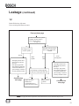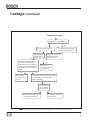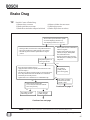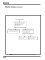
1
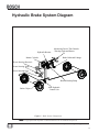
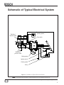
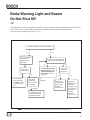
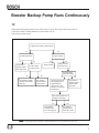
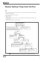
Class 5 to 7 Truck and Bus
Hydraulic Brake System
Diagnostic Guide
1st Edition
BOSCH
Important Service Notes
The information in this publication was current at the time of printing. The information
presented in this publication is subject to change without notice or liability.
The information contained in this publication is intended for use by properly trained and
equipped professional technicians. It is NOT for the “Do It Yourselfer”
Failure to follow safety and repair procedures can result in personal injury, or damage to
vehicles, components and equipment.
Failure to follow all the safety and vehicle repair procedures either contained in this manual, in the chassis and vehicle manufacturer's repair
manuals or in accordance with other accepted methods can result in
personal injury, death, or damage to components, vehicles, or personal
property.
Correspondence concerning this manual should be addressed to:
Robert Bosch Corporation
Attn: Hydraulic Actuation & Truck Brake Engineering
401 North Bendix Drive
South Bend, Indiana 46628
FAX: 574-237-2210
August 2003
Contents
Preface..................................................................................................................................... 3
Purpose of this diagnostic guide
Using this diagnostic guide
Exclusions
Brake System Diagram............................................................................................................. 4
Schematic of Typical Electrical System.....................................................................................5
Brake Warning Light and Buzzer Do Not Shut off.....................................................................6
Booster Backup Pump Runs Continuously.................................................................................7
Booster Backup Pump Does Not Run........................................................................................8
Brake Pedal Continues to Fall With Steady Foot Force............................................................ 9
Brake Pedal Feels Spongy, Soft or Springy............................................................................... 9
Brake Pedal Feels Very Hard................................................................................................... 10
Potential Master Cylinder and Booster Leak Points................................................................. 11
Leakage....................................................................................................................................12
Brake Drag...............................................................................................................................15
Master Cylinder Cap Diaphragms............................................................................................19
Low Shoe Pad Life or Uneven Shoe Pad Wear.......................................................................... 20
Printed in the United States of America
Copyright © 2003 Robert Bosch Corporation
Class 5 to 7 Truck & Bus Hydraulic Brake System Diagnostic Guide
3
1
Class 5 to 7 Truck & Bus Hydraulic Brake System Diagnostic Guide
4
2
Preface
Purpose Of This Diagnostic Guide
The purpose of this diagnostic guide is to assist Class 5 to 7 hydraulic brake repair technicians to more accurately and
quickly diagnose the most likely causes of a customer's brake related complaint.
This diagostic guide is NOT a repair instruction, but only a guide. When the probable cause of a customer's complaint is
established, the repair procedure must be done in accordance with the instructions in the vehicle manufacturer's service
manual.
Using This Diagnostic Guide
The brake technician must be able to understand the customer's complaints and description of the symptoms well
enough to match them to one (or more) of the categories listed in the Table of Contents. Most customer complaints
and symptoms on the vehicle can be matched to these categories. Each category has a corresponding flow chart that
will lead the brake technician to the most likely cause of the customer's complaints and vehicle symptoms. Several of
the flow chart paths end with a comment box that also includes a number. Brake technicians can use this number to
document why a Bosch manufactued part was replaced.
IMPORTANT REMINDER: The first step in diagnosing any customer complaint is to confirm the customer's
complaint and determine which category applies.
The flow charts show which diagnostic steps need to be taken. The brake technician must have the necessary skills
needed to perform each step. The flow charts are structured to guide the brake technician to take the quickest and
easiest steps first. Often, these first, simple steps will be enough to determine what repair needs to be made.
After completion of all diagnostic steps, the brake technician must remember to
tighten any tube nuts, fittings, bolts, screws, bleeder screws, etc., that were
loosened as part of the diagnostic procedure.
In all cases, the vehicle manufacturer's service manual must be used for any repair instructions.
Brake system warning lights and buzzers are unique to the vehicle manufacturer. The Brake Warning Light and
Buzzer Do Not Shut Off flow chart offered in this guide is generic and may not apply to all vehicles. The vehicle
manufacturer's service manual must be consulted in order to determine the proper function of these warning devices.
Exclusions
The ABS portion of the hydraulic brake system is not addressed in detail in this guide since the ABS hardware and
software are unique to the specific vehicle manufacturer. Any diagnosis or repair needs to be done in accordance with
the vehicle manufacturer's ABS service manual.
Class 5 to 7 Truck & Bus Hydraulic Brake System Diagnostic Guide
35
Hydraulic Brake System Diagram
Hydraulic Booster
Monitoring Device That Controls
Warning Light and Buzzer
Brake Pedal and Linkage
Master Cylinder
Power Steering Reservoir
Power Steering Pump
Power Steering Gear
Booster Backup Pump
Brake Caliper
ABS Hydraulic
Control Unit
Figure 1. Brake System Components
ΝΟΤΕ: Use appropriate brake component or vehicle manufacturer's service manual for all repair work.
Class 5 to 7 Truck & Bus Hydraulic Brake System Diagnostic Guide
6
4
Schematic of Typical Electrical System
Flow switch harness
ground (optional)
Fluid level
indicator switch
Flow switch
Differential
pressure switch
Backup pump
Ignition switch
Chassis ground
Relay
Figure 2. Schematic of Typical Electrical System
ΝΟΤΕ: Use appropriate brake component or vehicle manufacturer's service manual for all repair work.
Class 5 to 7 Truck & Bus Hydraulic Brake System Diagnostic Guide
7
5
Brake Warning Light and Buzzer
Do Not Shut Off
TIP
The light and buzzer come on together, typically in response to signals from the parking brake switch, booster
flow switch, master cylinder fluid level indicator switch, the master cylinder differential pressure
switch or booster backup pump (See Figure 2).
Is master cylinder reservoir more than 1/2 full?
No
Yes
Fill master cylinder
reservoir with
appropriate type
brake fluid.
Is the master cylinder differential
pressure switch closed to ground?
No
See Booster Backup Pump
Runs Continuously section
or Booster Backup Pump
Does Not Run section, as
appropriate.
Are light and
buzzer still ON?
No
- Check brake fluid
system for leakage
per Leakage section
- Check shoe pads for
wear
Yes
Yes
Check master
cylinder fluid
level reed switch
for continuity.
No
Continuity
Continuity
1
The problem is probably
with the master cylinder
fluid level reed switch.
Is there a leak
in the brake
fluid system?
No
2
The problem is
probably with the
master cylinder
differential
pressure switch.
Yes
Diagnose per
Leakage section.
After repair
completion, push
very hard on the
brake pedal to
shut OFF
differential
pressure switch.
ΝΟΤΕ: Use appropriate brake component or vehicle manufacturer's service manual for all repair work.
Class 5 to 7 Truck & Bus Hydraulic Brake System Diagnostic Guide
8
6
Booster Backup Pump Runs Continuously
TIP
The booster backup pump can run only if the relay is closed. The relay will be closed only if:
1) the flow switch is closed and there is power to the coil, or
2) the relay is stuck closed.
Is ignition key ON while condition exists?
Yes
No
Is engine running?
Are brake lights OFF?
No
No
Yes
The problem is
probably with the
brake light switch.
Yes
Normal condition
Is there voltage
to the relay coil?
Unplug connector
from flow switch
Is booster backup
pump still running?
No
3
The problem is probably
with the booster backup
pump relay.
Yes
No
The problem is
probably with the
ignition switch.
Yes
4
Check for proper power
steering pump flow by
rapidly rotating the
steering wheel. (The
alternative is to measure
the fluid flow.)
The problem is
probably with the
booster backup
pump relay.
Does steering wheel rotate
normally? Is flow OK?
No
The problem is
probably with the
power steering pump.
Yes
5 The problem is
probably with the
booster flow switch.
ΝΟΤΕ: Use appropriate brake component or vehicle manufacturer's service manual for all repair work.
Class 5 to 7 Truck & Bus Hydraulic Brake System Diagnostic Guide
9
77
Booster Backup Pump Does Not Run
TIP
The booster backup pump will not run if there is no voltage to the motor or if the motor is damaged
(e.g., burned out or jammed).
A no-voltage condition can occur because:
1) Battery is dead
2) Relay is stuck
3) Wires are broken (battery to motor circuit or ignition switch / brake light switch to booster flow
switch circuit)
4) Booster flow switch is not closed to ground
Is there proper voltage to
the booster backup pump?
No
Yes
- Disconnect booster flow switch connector
- Check continuity from relay to connector and
- Check continuity through flow switch
6
The problem is probably with
the booster backup pump.
Is wire
continuity OK?
No
Yes
7
The problem is
probably with the wire.
Is flow switch
continuity OK?
No
Yes
The problem is
probably with the
booster flow switch.
Is there voltage to
the relay coil?
No
Yes
Check ignition relay circuit and brake light
switch to relay circuit for continuity and
properly functioning switches.
Is there battery
voltage to the relay?
No
The problem is probably with
the battery to relay circuit.
Check it for continuity.
Yes
8
The problem is
probably with the relay.
ΝΟΤΕ: Use appropriate brake component or vehicle manufacturer's service manual for all repair work.
Class 5 to 7 Truck & Bus Hydraulic Brake System Diagnostic Guide
10
7
8
Brake Pedal Continues to Fall With
Steady Foot Force
Is there visible brake fluid leakage from:
- master cylinder?
- ABS hydraulic unit?
- disc brake calipers (watch for expanding piston boots)?
- tubes, hoses, or connections?
No
Yes
Is ABS light on?
No
9
The problem is probably due
to internal bypass of brake
fluid inside master cylinder.
See Leakage section.
Yes
The problem is probably
with ABS hydraulic unit.
Brake Pedal Feels Spongy, Soft or Springy
TIP
If the brake pedal does NOT fall with steady foot pressure but feels spongy, soft or springy, the problem is
probably caused by air trapped in the brake fluid system. Start by bleeding the brake system at the caliper
furthest from the master cylinder and work from the back to the front of the vehicle.
ΝΟΤΕ: Use appropriate brake component or vehicle manufacturer's service manual for all repair work.
Class 5 to 7 Truck & Bus Hydraulic Brake System Diagnostic Guide
11
99
Brake Pedal Feels Very Hard
TIP
The most common reasons for a very hard brake pedal are:
1) Insufficient flow or pressure from the power steering pump
2) The ABS hydraulic unit is blocking the flow of brake fluid to the calipers
With engine OFF, does
brake pedal feel very hard?
No
- Check for proper power steering
pump flow and pressure
- If the steering wheel cannot be
rotated rapidly, or if flow is
measured and found to be low,
the problem is probably with the
power steering pump
Yes
Does the booster
backup pump run?
No
Yes
See Booster Backup
Pump Does Not Run
section.
Does the booster backup
pump sound like it slows
down when pushing
harder on the pedal?
No
10
The problem is
probably with the
booster backup pump.
Yes
The problem is
probably with the ABS.
ΝΟΤΕ: Use appropriate brake component or vehicle manufacturer's service manual for all repair work.
Class 5 to 7 Truck & Bus Hydraulic Brake System Diagnostic Guide
12
10
Potential Master Cylinder and Booster
Leak Points
Flow switch seal
Booster outlet port
Inlet port seal
Reservoir to
body interface
Master cylinder
outlet ports
Booster to master
cylinder interface
Booster housing to
backup pump interface
Figure 3. Potential Master Cylinder and Booster Leak Points
ΝΟΤΕ: Use appropriate brake component or vehicle manufacturer's service manual for all repair work.
Class 5 to 7 Truck & Bus Hydraulic Brake System Diagnostic Guide
13
10
11
11
Leakage
TIP
Most external leakage is easy to detect by wetness and/or appearance of fluid drops. However, slight
dampness (no drops or wetness) may not indicate a leak.
Is the leak at the booster,
master cylinder, ABS
hydraulic unit, brake caliper,
or tubes and hoses?
Booster or Master
Cylinder
ABS
Caliper
Continued
Continued
on
on Next Page
next page
See ABS or vehicle
manufacturer’s
service manual.
Is leak at the bleed screw?
Yes
No
Tighten bleed screw to
manufacturer’s
recommended torque.
Is leak at the brake hose tube fitting?
Yes
No
Tighten tube fitting to
manufacturer’s
recommended torque.
Does it still leak?
No
Replace tube seat or bleed screw.
Tighten to manufacturer’s
recommended torque.
Complete
Does it still leak?
Yes
No
Complete
Yes
Replace tube seat or fitting.
Tighten to manufacturer’s
recommended torque.
Does it still leak?
No
Complete
Does it still leak?
No
Complete
Yes
12
The problem is
probably with the
caliper.
Yes
11 The problem is probably
with the caliper.
ΝΟΤΕ: Use appropriate brake component or vehicle manufacturer's service manual for all repair work.
Class 5 to 7 Truck & Bus Hydraulic Brake System Diagnostic Guide
14
12
Leakage
(continued)
TIP
Brake fluid mixes with water.
Power steering fluid floats on water.
From previous page
Examine booster & master cylinder
assembly. Is leak at booster to
master cylinder interface?
(See Figure 3)
Yes
No
Determine if the leak is brake
fluid or power steering fluid.
See TIP.
Is leakage at booster
or master cylinder?
Booster
- Thoroughly clean the entire
booster with soap & water,
then dry it
- Start engine, apply brakes
with normal foot pedal force
several times and look for a
point of leakage. Continue as
necessary until leak is found
Continued on
next page
Power
Steering Fluid
Brake
Fluid
Master
Cylinder
Can the leakage be fixed by tightening
the tube nuts or replacing the tube seats?
- Thoroughly clean the entire
booster with soap & water,
then dry it
- Start engine, apply brakes
with normal foot pedal force
several times and look for a
point of leakage. Continue as
necessary until leak is found
No
Yes
Tighten tube nuts to
manufacturer’s
recommended torque or
replace tube seats as needed.
13
Replace master
cylinder.
Continued on
next page
ΝΟΤΕ: Use appropriate brake component or vehicle manufacturer's service manual for all repair work.
Class 5 to 7 Truck & Bus Hydraulic Brake System Diagnostic Guide
15
13
13
Leakage
(continued)
From previous page
Is booster flow switch leaking?
Yes
No
Is leak at booster inlet port?
No
Yes
Is leak at booster
backup pump?
No
Is leak at the interface between
the booster housing and the
backup pump? Or, if an adapter is
present, between the adapter and
the housing or the adapter and the
pump?
No
16
The problem is
probably with the
booster.
14
The problem is probably with
the flow switch O-ring seal.
The problem is probably
with the booster inlet
fitting O-ring seal.
Yes
15
The problem is
probably with the
backup pump.
Yes
Clean and examine all sealing surfaces and
seal grooves at backup pump, booster
housing, and adapter.
Are surfaces and
grooves flat and
free of damage?
No
17 The problem is probably with
the damaged component.
Yes
18
The problem is probably
with the seals.
ΝΟΤΕ: Use appropriate brake component or vehicle manufacturer's service manual for all repair work.
Class 5 to 7 Truck & Bus Hydraulic Brake System Diagnostic Guide
16
14
Brake Drag
TIP Possible Causes of Brake Drag:
1) Booster does not return
2) Brake pedal does not return
3) Brake hoses and tubes collapsed or kinked
4) Master cylinder does not return
5) ABS traps pressure
6) Brake caliper does not release
- Remove filler cap from the master cylinder
- Look at the diaphragm, inside the cap
- Is the diaphragm swollen (See Figure 4)
No
Yes
- With engine OFF, measure location of the pedal from the floor
- Start engine and measure if pedal dropped to a new position
- Shut OFF engine and measure if pedal returned to original
position
Did pedal drop about 1/2"
when engine started?
No
Yes
Two people will be needed for this step.
- Apply and release brakes, then quickly loosen bleed screw at the
suspected caliper(s).
- The bleed screw must be loosened quickly, in case trapped pressure
at the caliper bleeds down before the bleeder screw is loosened.
- Does fluid spurt out under pressure?
- Tighten bleed screw to manufacturer’s recommended torque.
No
- Remove caliper and shoe pads
- For rear axle, disconnect axle from hub
- Does rotor spin freely
No
Master cylinder has been contaminated
with the wrong fluid.
- Replace all of the following: master
cylinder, all calipers, ABS hydraulic
unit, and all rubber hoses.
- Flush the steel brake tubes with clean
brake fluid prior to installing new brake
components.
The problem is
probably with the
power steering pump.
Yes
The problem is probably
with the booster, master
cylinder or ABS.
Continued on page 17
Yes
The problem is probably
with bearing pre-load.
Caliper assembly is
probably dragging.
Continued on next page
ΝΟΤΕ: Use appropriate brake component or vehicle manufacturer's service manual for all repair work.
Class 5 to 7 Truck & Bus Hydraulic Brake System Diagnostic Guide
17
15
15
Brake Drag
(continued)
From previous page
- Replace caliper without shoe pads, and
tighten slide pin bolts in proper sequence
and to correct torque
- Slide caliper in and out by hand
- Does caliper move freely
No
19
The problem is probably with the pins, if
pin slide, or rails, if rail slide type brake.
Yes
- Remove caliper and replace shoe pads
- Slide shoe pads side to side
- Do shoe pads move freely
No
20
The problem is probably
with the shoe pads.
Yes
21
The problem is probably with
the pistons in the caliper.
ΝΟΤΕ: Use appropriate brake component or vehicle manufacturer's service manual for all repair work.
Class 5 to 7 Truck & Bus Hydraulic Brake System Diagnostic Guide
18
16
Brake Drag
(continued)
TIP
Prior to moving master cylinder 1/8 inch away from booster, loosen two diagonally opposed nuts that hold the
master cylinder to the booster, by 1/8 inch. Have a power tool ready to loosen the remaining two nuts after the
brakes have been applied and released.
From page 15
Two people will be needed to do this step.
- Apply and release brakes, then quickly loosen primary brake line tube nut
at the master cylinder.
- The tube nut must be loosened quickly in case trapped pressure at
the master cylinder bleeds down before the tube nut is loosened.
Does fluid spurt out under pressure
at the brake line tube nut?
Yes
No
-
- Tighten brake line tube nut to
manufacturer’s recommended torque
- Apply and release brakes, then quickly
loosen secondary brake line tube nut
- Retighten tube nut
The problem is
probably with
the ABS.
No
Does fluid spurt out
under pressure at the
brake line tube nut?
Yes
Two people will be needed for this step.
- Tighten tube nuts to manufacturer’s recommended
torque.
- Apply and release brakes.
- Shut-off engine.
- After releasing brakes, quickly loosen the four nuts (see
TIP) holding the master cylinder to booster, by 1/8 inch.
- Quickly pull master cylinder away from booster, and
quickly loosen primary brake line tube nut.
- All of these steps must be done quickly in case trapped
pressure at the master cylinder bleeds down before the
tube nut is loosened.
Continued on next page
ΝΟΤΕ: Use appropriate brake component or vehicle manufacturer's service manual for all repair work.
Class 5 to 7 Truck & Bus Hydraulic Brake System Diagnostic Guide
19
17
Brake Drag
(continued)
From previous page
Does fluid spurt out under pressure
at the tube nut?
No
Yes
- The problem is probably with
the booster or pedal linkage
- Retighten tube nut
- Retighten 4 nuts to 34 to 41 Nm
22
The problem is probably
with the master cylinder.
Apply and release brakes, then quickly do the following:
- Remove pin that holds the pedal rod to the pedal arm.
- Open primary tube nut at master cylinder.
- These steps must be done quickly in case trapped pressure in the
master cylinder bleeds down before the tube nut is loosened.
Does fluid spurt out under pressure at the tube nut?
No
Yes
- Retighten the tube nut
-The problem is probably with
the pedal linkage
23
- Retighten the tube nut
- The problem is probably
with the booster
ΝΟΤΕ: Use appropriate brake component or vehicle manufacturer's service manual for all repair work.
Class 5 to 7 Truck & Bus Hydraulic Brake System Diagnostic Guide
20
1817
Master Cylinder Cap Diaphragms
Diaphragm swollen due to exposure to mineral oil
(power steering fluid, automatic transmission
fluid, motor oil, etc.)
Normal diaphragm
Figure 4. Comparison: Swollen vs. Normal Diaphragm
ΝΟΤΕ: Use appropriate brake component or vehicle manufacturer's service manual for all repair work.
Class 5 to 7 Truck & Bus Hydraulic Brake System Diagnostic Guide
21
19
19
19
Low Shoe Pad Life or Uneven Shoe Pad
Wear
TIP
Shoe pad life can vary greatly due to many factors including vehicle type, vocation (e.g., rollback tow truck,
box truck, bus, etc.), terrain, urban vs. rural use, and driver style. Therefore, no guidelines can be provided for
the mileage that should be obtained.
Verify condition that shoe
pads are wearing abnormally
(excessive inner vs. outer
shoe pad wear).
Are brakes dragging?
No
Yes
Do brakes show signs of heat exposure?
No
For low brake operating
temperature conditions,
see service manual for
appropriate alternate
replacement shoe pads.
See Brake Drag section.
Yes
Condition is probably
related to the duty cycle
(usage) or the driver’s
braking habits.
ΝΟΤΕ: Use appropriate brake component or vehicle manufacturer's service manual for all repair work.
Class 5 to 7 Truck & Bus Hydraulic Brake System Diagnostic Guide
22
20
Correspondence concerning this manual should be addressed to:
Robert Bosch Corporation
Attn: Hydraulic Actuation & Truck Brake Engineering
401 North Bendix Drive
South Bend, Indiana 46628
Fax: 574-237-2210
Printed in the United States of America
Copyright © 2003 Robert Bosch Corporation