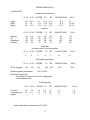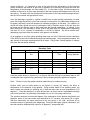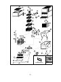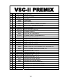
1
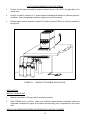
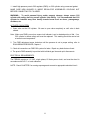
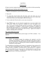
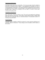
PREMIX
SERVICE AND INSTALLATION MANUAL
TOPPER PREMIX
ICE COOLED PREMIX
TOPPER II PREMIX
VSC-II PREMIX
BIG FELLA PREMIX
CONCEPT PREMIX
IC
I
INTERNATIONAL CARBONIC INC.
16630 Koala Rd.
Adelanto, California 92301
800 854-1177
1/00
IMPORTANT:
This manual is a guide for installing,
operating, servicing and maintaining this equipment.
Refer to Table of Contents for page location of detailed
information to answer questions that arise during
installation, operating, service and maintenance, or
trouble shooting this equipment.
TABLE OF CONTENTS
PAGE
Chapter I
General Description .............................................................................................................. 1
System Description ............................................................................................................... 1
Premix Design Data ........................................................................................................................... 2
Cooling Unit........................................................................................................................... 2
Overall Cabinet Dimensions ................................................................................................. 2
Weights ................................................................................................................................. 2
Capacities ............................................................................................................................. 2
Refrigerant Requirement....................................................................................................... 2
Electrical Requirement .......................................................................................................... 2
Circuit Ampacity .................................................................................................................... 2
Theory of Operation ........................................................................................................................... 3
The flow of Premix, Mechanical Unit..................................................................................... 3
The flow of Premix, Ice Cooled ............................................................................................. 3
The flow of Carbon Dioxide................................................................................................... 3
Carbonation........................................................................................................................................ 4
Equilibrium Pressure .......................................................................................................................... 6
Operating Pressure ............................................................................................................................ 7
Less Than Equilibrium........................................................................................................................ 8
Over Equilibrium Pressure ................................................................................................................. 8
Changing Product Volumes of CO2 Gas ........................................................................................... 8
Chapter II Installation ......................................................................................................................... 9
Unpacking and Inspection..................................................................................................... 9
Loose Shipped Parts............................................................................................................. 9
Selecting Location................................................................................................................. 9
Location Recommendations for Premix ............................................................................................. 10
Installation ............................................................................................................................. 10
Install Cooling Unit ................................................................................................................ 10
Install High Pressure Premix CO2 Regulator and CO2 Cylinder....................................................... 10
Activate CO2 System ............................................................................................................ 11
Electrical Requirements ........................................................................................................ 11
Chapter III Preparation....................................................................................................................... 12
Preparing and Starting Refrigeration Unit ............................................................................. 12
Daily Pre-Operation Check ................................................................................................... 12
Cooling Unit Maintenance ..................................................................................................... 12
Checking Water Bath ............................................................................................................ 13
Changing Water Bath............................................................................................................ 13
Adjustments .......................................................................................................................... 13
Chapter IV Service and Maintenance ................................................................................................ 14
Periodic Inspection and Cleaning ......................................................................................... 14
Exploded View LF-12 Pre-Mix .............................................................................................. 15
Exploded View Description, LF-12 Pre-Mix .......................................................................... 16
Exploded View LF-23 Pre-Mix .............................................................................................. 18
Exploded View Description, LF-23 Pre-Mix .......................................................................... 19
Exploded View Topper Pre-Mix ............................................................................................ 21
Exploded View Description, Topper Pre-Mix ........................................................................ 22
Exploded View Topper-II Pre-Mix ......................................................................................... 24
Exploded View Description Topper-II Pre-Mix ...................................................................... 26
Exploded View Big Fella Pre-Mix.......................................................................................... 27
Exploded View Description Big Fella Pre-Mix....................................................................... 28
Exploded View Concept Pre-Mix .......................................................................................... 30
Exploded View Description Concept Pre-Mix ....................................................................... 31
Exploded View VSC-II Pre-Mix ............................................................................................. 33
Exploded View Description VSC-II Pre-Mix .......................................................................... 34
Exploded View Pre-Mix Valve............................................................................................... 36
Premix Trouble Shooting.................................................................................................................... 37
Product Will Not Dispense .................................................................................................... 37
Product Foams While Being Dispensed ............................................................................... 37
Frozen Water Bath ................................................................................................................ 38
Condensing Unit Non-Operational ........................................................................................ 38
Compressor Does Not Operate ............................................................................................ 38
Compressor Works Continuously But Does Not Cool Sufficiently........................................ 39
Compressor Will Not Stop After Cooling Pre-mix Product.................................................... 39
Condenser Fan Motor Not Operating.................................................................................... 39
PREFACE
INTERNATIONAL CARBONIC INC. has enjoyed over 53 years of manufacturing
excellence in the field of carbonation and in the beverage related industry. We have
had a long and proud history with quality as our standard and innovation as our goal.
Originally started just after World War II in Canfield, Ohio as Carbonic Dispensers. We
enjoyed patents on the first Sodajet type carbonator. This method of carbonation
instantaneously carbonated the water to 100% saturation. We developed the first
patented dispensing valve to dispense bulk beverage with carbonation equal to or in
excess of bottled beverages. A valve with three flavors and soda was another first. We
were the first to incorporate the total postmix package, i.e., carbonation, refrigeration,
and the ability to dispense from one self contained unit. We have pioneered many such
firsts and will continue to develop advanced systems for the future, such as electronic
interrogatable portion controls to electronic liquid level controls.
We hope you enjoy this piece of equipment that has been produced to give many years
of trouble free service. We thank you for your purchase and hope we may serve you in
the future.
CHAPTER I
GENERAL DESCRIPTION
This chapter gives the description, theory of operation, and design data for PREMIX units and
related components.
A PREMIX unit can be manufactured as a LF-12, LF-23, BIG FELLA, TOPPER, TOPPER-II,
CONCEPT-6000 VSC-II or in a variety of ice cooled type cold plate systems. Special
application PREMIX units can be manufactured on request, contact factory.
SYSTEM DESCRIPTION
A PREMIX unit will cool and dispense a carbonated beverage that has been carbonated and
mixed in a proper syrup ratio in a location other than the point of sale. PREMIX locations are
normally set up for short duration dispensing were it is impractical to install a post mix unit. A
PREMIX install is normally reserved for special events were the volume of draw will be to great
to handle with bottle and cans.
The PREMIX refrigerated unit consists of a cabinet, condensing unit, a water bath, product
cooling coils, (one for each product), an agitator pump, and dispensing valve(s). Ice cooled
units consists of a cabinet, dispensing valves, cold plate with individual passes for each flavor.
For proper function the PREMIX unit only requires an electrical supply for mechanically
refrigerated models and drainage. For proper function ice cooled units will require drainage, but
the availability of electricity is not necessary. Other items that will be required to perform a
functional installation will be a CO2 supply, a premix pressure regulator, connecting lines, and
quick disconnects.
WARNING: Before shipping or relocating a PREMIX unit into a freezing ambient
environment drain and relieve all pressure from individual premix passes in unit.
A freezing ambient environment will cause existing product in unit to freeze
possibly resulting in damage to individual passes.
1
TABLE I - I
PREMIX DESIGN DATA
COOLING UNIT
Overall cabinet dimensions:
LF-12
Height
Width
Depth
23 ½
12
26
LF-23
TOPPER
T-II
23 ½
23
12 ¾
30
13 ¼
19 ½
32 ½
15 ¾
21 ½
BF
CONCEPT-6000
VSC-II
33 ¼
16 ¾
22 ¾
33
16 3/8
24 1/2
29 ¼
26 ½
16 ½
Weights:
LF-12
Shipping
Dry
Operational
Ice Bank
115
90
123
9.5
LF-23
TOPPER
115
90
123
9.5
115
90
132
12
T-II
142
108
199
30
BF
CONCEPT-6000
145
117
183
35
174
132
232
35
VSC-II
173
141
250
50
Capacities:
Unit water bath (no ice bank) gallons
LF-12
4
LF-23
4
TOPPER
5
T-II
11
BF
7
CONCEPT-6000
12
VSC-II
13
Refrigerant requirement
(R-134-A) grams
LF-12
LF-23
TOPPER
T-II
BF
165
165
155
184
250
Ambient operating temperature
CONCEPT-6000
350
VSC-II
258
40 F to 100 F.
Electrical Requirements:
The cooling unit requires a 115 VAC, single phase,
60 Hertz power circuit.
Circuit Ampacity
LF-12
Unit total
Condensing Unit
Agitator
3.5
2.5
1
LF-23
3.5
2.5
1
TOPPER T-II
3.5
2.5
1
6.0
5.0
1
Ambient Operating Temperature 40 F to 100 F
2
BF
7.8
6.8
1
CONCEPT-6000
7.8
6.8
1
VSC-II
7.8
6.8
1
THEORY OF OPERATION
The PREMIX unit was designed to cool and dispense a carbonated beverage that has been
manufactured at your local bottling plant.
The premix product is contained and transferred in a five-gallon transfer tank referred to as a
FIGAL. The FIGAL is kept under pressure with CO2 and should remain under pressure at all
times.
The pressure in the tank will vary with the ambient temperature. If a premix FIGAL is stored in a
very cold location the amount of carbonation, refereed to as volumes of CO2, may increase in
the premix product. This increase in carbonation will not happen instantly but will occur over a
long period of time. The ideal volume to dispense the premix product is 3.5 or 3.6, any higher in
volumes will cause foamy drinks.
The flow of the PREMIX product from the FIGAL through a mechanically refrigerated unit is as
follows:
The product flows through the outlet on the FIGAL, through a quick disconnect into and
through the beverage tubing entering the unit. The product flows through ¼” inner braid
tubing, until it reaches a submerged cooling or premix coil. This coil is submerged in a
water bath that is kept at a temperature of approximately 32.5 degrees. As it passes
through this cooling coil the temperature of the premix product is greatly reduced until
the temperature is sufficient to dispense a quality drink. The product is finally routed
through a premix faucet. The volume of flow will be controlled by an adjustment on the
premix faucet. The number of premix coils will depend on the number of flavors required
and space available.
The flow of the PREMIX product from the FIGAL through an Ice Cooled unit is as follows:
The product flows through the outlet on the FIGAL, through a quick disconnect into the
beverage tubing entering the unit. The product flows through ¼” inner braid tubing until
it reaches a stainless steel serpentine coil incased in 99.7% pure aluminum, (the cold
Plate). This serpentine coil refereed to as a pass will be of sufficient length to cool the
premix product to a sufficient temperature to dispense a quality drink. The number of
passes in a cold plate will depend the number of products to be cooled, required length
of pass and space available to accommodate the cold plate. For the cold plate to
function, ice must cover the cold plate. As the premix product passes through a pass
the temperature of the premix product is greatly reduced until the temperature is
sufficient to dispense a quality drink. The product is finally routed through a premix
faucet. The volume of flow will be controlled by an adjustment on the premix faucet.
Never use ice directly from a freezer.
THE FLOW OF CARBON DIOXIDE GAS (CO2)
Carbon dioxide gas (CO2) passes from a C02 cylinder through high-pressure premix regulator.
The high-pressure premix regulator should be set at a sufficient pressure to keep equilibrium
pressure for the premix product. The gas, after leaving the high-pressure premix regulator is
routed to individual FIGALS. The average settings may vary this of course will be influenced by
temperature and length of run.
3
CARBONATION
Volumes of carbonation is the amount of gas that is dissolved in the carbonated beverage. This
is determined by temperature and pressure and can be read by the use of a Carbonation
Tester. The volume means simply the relative bulk of gas dissolved in the liquid and, although it
seems odd that several bulk volumes of gas will disappear into one bulk volume of water, yet
this is a phenomenon known as gas solution. To bring about the gas solution, pressure is
needed, and when the pressure is released on the gas, out it comes again.
When the pressure of the carbon dioxide gas is only that of the atmosphere in which we live, we
find that the gas dissolves in amounts determined by the temperature of the water. Gas will
dissolve without pressure from 1.71 volumes at the freezing temperature of water to 0.56
volumes at 100 degrees F.
To get greater amounts of carbon dioxide into solution, it is necessary to increase the pressure
of the gas on the water. This is indicated on a carbonation tester by the increase in volumes
and the gauge pressure begins at zero, (which is atmospheric pressure), and proceeds on to 30
pounds per square inch. The important thing to notice is that every time the gas pressure is
increased by 14.7 pounds per square inch, the gas content increases on multiple of the
atmospheric pressure, for a given temperature. For example, we find that at 60 degrees F. one
volume of carbon dioxide will dissolve in one volume of product at atmospheric pressure, (zero
#/sp. In. on gauge). Then as the gauge pressure reaches 14.7, the amount of gas dissolved
becomes 2.0 volumes, at 29.4 the amount of gas is 3.0 volumes. At 44.1 the amount of gas is
4.0 volumes, etc. This same multiple ratio of solubility holds true at normally used temperatures
and pressures.
In practice, the amounts of gas wanted are such that pressure is needed to get the amounts of
“load” of carbon dioxide in the liquid and by such process the gas is placed in a “tension” in the
liquid, and is held there by the pressure placed on it. To a certain extent, this is the same as
placing pressure on a long, coiled spring and compacting it. As long as the pressure is
maintained, it stays compacted, but as the pressure is released, it uncoils regularly until all of
this load tension is gone. So it is with carbonated liquids – the gas content or “load” is held in by
pressure creating a tension on the gas in the liquid so that when the pressure is removed,
(when the bottle is opened), the gas moves out of the liquid until it is back to the original
conditions before the pressure was applied.
The next important consideration is the effect that the varying degrees of carbonation will have
on the finished beverage, its appearance, taste, and general behavior.
Depending somewhat on the type of beverage, carbonation much above 3.5 volumes tend to
throw off too much carbon dioxide in the mouth and throat, causing choking or irritation. It is
quite satisfactory, therefore, to say that for the majority of products it is not necessary to have
over 3.5 volumes of gas in the beverage at the time it is going into the consumer’s mouth, to
give the most desirable pungency or taste sensation. However, since there is always some gas
lost when the drink is poured an additional gas content must be considered.
The amounts of carbon dioxide lost as a beverage is dispensed vary. The gas loss is negligible
when the product has been cooled and not unduly disturbed. However, when the beverage is
poured into a glass, mechanical agitation takes place that more or less tends to throw the gas
out of the liquid. As long as the gas loss in pouring does not become so great that the resulting
beverage has dropped below the reasonable taste range and becomes dead, it is not wasted,
for the bubbles formed furnish a direct eye appeal. It is not uncommon to find that from 0.5 to
3.0 or more volumes of gas have been lost just in the dispensing. The more agitation that
occurs from either having a spoon or cracked ice in the glass or pouring from a higher point that
just at the lip of the glass tends to increase the gas loss, and is often the
4
cause of flatness. It’s important to note at this point that the temperature of the beverage
greatly influences the amount of gas loss by agitation, the tendency being that the lower the
temperature of the beverage, the more stable it is. It is far better to pour a cold beverage over
cracked ice than to try to pour warm beverage in the same manner and depend on the ice to do
the cooling. The latter case the disturbance will take place in the carbonated beverage before it
has time to be cooled, and gas loss will occur.
Once the beverage is placed in a glass it should have at least enough carbonation to show
some life during the period in which the beverage is being drunk, the carbonation being part of
its appeal, and lastly it must still possess its necessary pungency to the taste. If by chance it is
mixed with other liquids that are not carbonated, they will absorb some of the gas from the
beverage and will thereby tend to dilute and lower the general carbonation. In general, it has
been found that if the beverage is finally quiet in the glass after the disturbance of dispensing
with from 2.5 to 3.5 volumes of carbonation, it will not be lifeless. As will be shown later,
attempting to get more than this amount in the glass is not feasible.
As an example, a very fine quality sparkling water was run in the Technical Service Laboratory
of the NSDA to see how it behaved during these handling steps. Using a special procedure, the
gas content of the water was determined at all steps. Using clean, cooled glasses of ordinary
size, here are the results obtained:
Conditions
Orig. Carb.
Very carefully
Average
Poured over
cracked ice
#1
42 Degrees F.
fine
4.5
4
3.4
2.3
Carbonation
Retention Tests
#2
82 Degrees F. fine
4.5
3.1
2.1
1.7
#3
42 Degrees F.
Fine
#4
42 Degrees F.
foreign particles
5.5
4.1
3.2
---
5.5
3
2.6
2.1
From the results shown in column #1, it is obvious that with the best of conditions there is still
considerable loss of gas serving, particularly if the beverage gets badly agitated in the glass.
Note:
Product of very high quality could be made inferior by careless serving.
Another factor can be easily shown by the figures in column #2, namely, the effect of
temperature on the behavior of the product. Using another bottle of fine sparkling water, the
same routine was carried out, differing only in that the water was at room temperature of 82
degrees F. From this example, it is quite obvious that it is wise to serve a carbonated beverage
well cooled, and that it is particularly undesirable to try to cool it by using cracked ice.
The question arises as to what would happen if the carbonation of this product was raised, and
therefore, some of the same water was carbonated to 5.5 volumes, see column #3 on table.
With this carbonation, the water was found to be very touchy, if not “wild”, and threw off an
excessive amount of gas during the dispensing. Even with the higher original carbonation, the
best that could be obtained when cooled to 42 degrees F. and poured with
5
great care into a glass was a gas content in the glass of 4.1 volumes, which compared with the
4.0 volumes resulting in the first experiment using the lower carbonation. But the interesting
fact came when this higher carbonated water was poured in an average manner into a glass, for
the carbonation remaining after pouring dropped to 3.2 volumes, which showed a difinte loss as
compared to the 3.4 volumes in the final glass of carbonated water using the lower carbonation.
Boosting the carbonation made the product poured out in the glass less lively than before. The
natural question is, why cannot more gas be put in a beverage be yound a reasonable amount
to obtain better life? The answer lies in the “load” of gas which exerts a very definite strain or
tension in the liquid as it is served.
In another test, a sparkling water which showed suspended matter obvious in the bottle when
the water was examined by a strong cross lighting was run in the same manner as was the first
water mentioned. This latter water was the same carbonation as before, 4.5 volumes and the
water was poured into the glasses at a temperature of 42 degrees F. When these results are
compared with the sparkling water first mentioned, it becomes quite obvious that the particles
suspended in the water had a very destructive effect on the carbonation.
These particles are generally spoken of as nuclei on which bubbles form, and experimentally
with unusually clean apparatus, it has been possible to go to excessive carbonation without any
tendency for bubbles to form when the pressures are released. It is, therefore, believed that in
the majority of cases these particles are necessary to let the gas unload, and that those
particles showing negative charge are the most likely to cause this phenomenon, for some
particles without the necessary charge will not cause bubbles to form. To observe on any given
product, the reasonably cool bottle should be opened quietly by taking the crown off slowly, (the
bottle should also have stood quietly for at least 15 minutes before the test). Then with cross
lighting watch to see where bubbles of gas form. Where the water is extremely clear and bright,
and the bottle well washed, with a clean inner surface, bubbles will form a very slow bubbling.
If, however, there are a number of active particles or nuclei present, bubbles will form rapidly in
the body of the liquid. Particles may even be seen dancing around in the liquid, with a feather
or stream of bubbles arising as they do. If the bottle is dirty, the bubbles will form at excessive
rates on the glass surface. In general, the elimination of such difficulties is through better
clarification of the water used, or better cleaning of the inside of the container the product is
carried in or dispensed into. To show how particles affect a product, flick some salt in a well
carbonated beverage and watch the rapid gas loss. The sharpened end of a lead pencil will
have the same effect.
A very logical question is often asked as to whether or not there is any way that the gas can
come out of carbonated beverages than through bubbles. The answer is that the gas can leave
by a substantially invisible process known as diffusion, in which the gas moves slowly through
the open surfaces of the beverage and into the surrounding atmosphere. Diffusion will cease as
soon as the pressure have equalized.
It may be said that the indication of how fast the beverage is losing its gas is directly indicated
by the speed of bubble formation. Then it can also be said that rapid bubble formation in a
beverage may indicate life at the particular moment, but the product which will stay alive the
longest on standing is one which may appear almost dead and will bubble only when disturbed.
Even though the bubbles forming at any one time appear to have only a small volume, they
rapidly amount to an appreciable amount of gas.
EQUILIBRIUM PRESSURE
A FIGAL that has counter or head pressure of equilibrium is one that has pressure just sufficient
to keep the recommended volume of CO2 gas absorbed in the product at a particular product
temperature.
6
This equilibrium pressure is not a constant. It varies with the change in the product
temperature. As the product temperature increases, equilibrium pressure also increases. This
is caused by the fact that a container of water without any head pressure will absorb 1.71
volumes of CO2 gas at 32 degrees F. and on .56 volumes of CO2 gas at 100 Degree F. If the
pressure is not increased as the product temperature rises, the product will lose .017 volumes of
carbonation per degree of temperature rise.
OPERATING PRESSURE
Operating pressure is equilibrium pressure plus enough pressure to overcome pressure loss or
resistance caused by the peculiarities of any specific system. Some of the peculiarities
encountered that offer a system resistance are, (a) Manifolding together of more than one tank
of product in the system. (b) Operating pressure may have to pump product through lines of a
considerable distance. (c) Operating pressure may have to lift the product in a vertical lift, such
as from the first floor product storage to a second floor unit installation.
For these reasons, the correct operating pressure for any specific system must be determined
according to the peculiarities of the equipment installation.
Experience has indicated that for the simplest of installations where the product lines are short,
not more than two or three tanks of product are connected in a series at one time, and the tanks
are on the same floor as the dispensing apparatus, setting the operating pressure at five pounds
more than equilibrium pressure is usually a good rule of thumb. In the case of the above
system, if the product is carbonated at 3.6 volumes and the product temperature is 70 degree
F., forty-eight pounds is equilibrium pressure and fifty-three pounds would be operating
pressure.
It is suggested that five pounds additional pressure be used as a starting point to which should
be added amounts of pressure to compensate for more rugged conditions than those in the
above example. For instance, if the tanks are located on the floor below the dispensing station,
one pound of pressure should be added to our standard amount of five pounds for every two
feet of vertical distance between the top of the FIGAL and the dispensing valves on the floor
above.
If, for example, this distance were to be ten feet the resulting five pounds additional pressure
should be added to our standard five, bringing the total to ten pounds of additional pressure to
be added to the equilibrium pressure in order to obtain the operating pressure for our CO2
regulator.
In this same example, if the product lines between the FIGAL and the unit are quite long,
approximately one pound of additional pressure should be added for every ten feet of product
line over a basic length of ten feet, which is compensated for in the original standard addition of
five pounds; Therefore, if the product lines are thirty feet long, two additional pounds should be
added to the ten pounds already arrived at for this example.
If, in addition, the above installation required five FIGAL’s in one series rather than the average
of three or less, one pound should be added to the previous result of twelve pound for each
additional tank over three. In this example, if two pounds were added to the original twelve
pounds, then the proper operating pressure for this system would be fourteen pounds above
equilibrium pressure.
In determining the equilibrium pressure for a product in an installation, the highest temperature
encountered by the product between the tank storage area and the cooling source must be
considered. It should be remembered that the above rules are not absolute, but have evolved,
for the most part, from experience. While these rules will generally hold true, they should be
considered as merely a starting point for further experience and common sense in dealing with
7
the many abnormal conditions often found in the customers place of business.
LESS THAN EQUILIBRIUM
Attempting to dispense product at less than equilibrium is probably the greatest cause of
foaming complaints and flat product. Foaming generally occurs when operating pressure is
slightly lower than it should be or when the cooling unit is not doing an adequate job and the
product is being dispensed in most cases above forty degrees F. Spitting at the dispensing
valve is usually caused by operating pressure being considerably lower than it should be. In the
case of spitting, gas is leaving the product rapidly in the form of large bubbles not only during
dispensing, but also while the system is at rest. These large bubbles will flow to the highest
points in the product line or cooling unit and form gas pockets. Spitting occurs when these gas
pockets are forced through the lines and arrive at the dispensing valve.
Even though the cooling unit lowers the product temperature so that the equilibrium pressure is
lower, there is no way of putting the CO2 gas back into the product while it is in the lines.
OVER EQUILIBRIUM PRESSURE
Pressure in excess of equilibrium can in a period of time change the volume of CO2 gas held by
the product. As mentioned under “equilibrium Pressure,” temperature of the product has a great
effect upon the acceptance or rejection of CO2 gas by the product. As and example, if the
product were stored in a cool area and the product temperature is 45 degree F. and equilibrium
pressure is exceeded by ten pounds, then the product CO2 volumes would be increased by .8
in approximately 16 hours if this is a 3.6 volume product to begin with. If the product is a 4.0
volume product, then it increases .9 in approximately 16 hours. According to the temperature
rule, if the product temperature were lower than 45 degrees and the over-pressure greater than
ten pounds, the increase in the product carbonation would be greater in a shorter period of time.
Since 70 degree product carbonated at 3.6 volumes will pick up only .53 volumes of gas in
approximately sixty hours and 4.0 volume product in the above example picks up only .55
volumes in sixty hours, it is, therefore, a good practice especially when substantial overpressures are required to place the product tanks in as warm an area as possible. Warm
product will gain fewer volumes and require a longer period of time for absorption than cold
product, given the same amount of over pressure.
CHANGING PRODUCT VOLUMES OF CO2 GAS
If the product should be found “flat” the volumes of CO2 gas can be increased to the
recommended volumes by finding equilibrium pressure for the temperature of the product. Set
this pressure on the CO2 regulator, attach gas line to the product tank, and shake the tank
vigorously until CO2 gas is no longer heard entering the tank. The lower the product
temperature, the less shaking will be required to bring product volumes of CO2 to
recommended point.
If product should be found “over-carbonated”, then excess volumes can be released by relieving
the head or counter-pressure in the product tank. After this is done, shake the tank vigorously:
this causes product to give off CO2 gas to replace pressure in headspace.
If the product is only slightly over-carbonated, then usually one such operation is all that is
required. Be sure to test, and if required, repeat operation of relieving counter-pressure and
releasing CO2 gas from product until recommended volumes are obtained.
If a full tank has the head pressure released and then is shaken, the gas released to replace the
head pressure will reduce the product carbonation by approximately .2 of a volume if the
product was 4.0 volume.
8
CHAPTER II
INSTALLATION
This chapter covers unpacking, inspection, selecting location, installing PREMIX UNITS and
related components and electrical requirements.
UNPACKING AND INSPECTION
Upon receiving unit, immediately remove unit from shipping carton and inspect for shipping
damage.
NOTE: Before leaving the factory all PREMIX units were carefully inspected and the carrier has
accepted and signed for them. Any damage or irregularities should be noted at the time of
delivery and immediately reported to delivering carrier. Request a written inspection report from
claims inspector to substantiate any necessary claim. File claim with delivering agency, not
International Carbonic Inc.!
Unpack LOOSE-SHIPPED PARTS. At this time make sure all parts listed are present and in
good condition. If any parts are missing, notify factory.
TABLE 2-1
LOOSE - SHIPPED PARTS
MODEL
II
S-1149 Drip Tray
S-1149A Cup Rest
S-1150 Drip Tray
S-1150A Cup Rest
S-1156 Drip Tray
S-1156A Cup Rest
S-1157 Drip Tray
S-1157A Cup Rest
S-1158 Drip Tray
S-1158A Cup Rest
PMR-4 (Reg. Assembly)
PMR-5 (Reg. Assembly)
Decals
Service Manual
LF-12 LF-23
X
X
TOPPER
T-II
BF
CONCEPT-6000
VSC-
X
X
X
X
X
X
X
X
X
X
X
X
X
X
X
X
X
X
X
X
X
X
X
X
X
X
X
X
X
X
X
X
X
SELECTING LOCATION
IMPORTANT: Ambient temperature for PREMIX should not exceed 100 degrees “F”.
Operation of cooling unit in ambient above 100 degrees “F” can and will contribute to early
failure of condensing unit and poor quality of finished product.
9
LOCATION RECOMMENDATIONS FOR PREMIX
1.
Position unit as close as possible to proper electrical source, 115V 60HZ, not applicable to ice
cooled units.
2.
Position unit with a minimum of 2” space between bulkhead and cabinet for sufficient space for
ventilation. Allow enough space between ceiling and unit for lid removal.
3.
Enough space must be allowed to install C02 cylinder, product FIGAL’s as close as possible to
serving unit.
FIGURE 2-1.
SAMPLE OF POSSIBLE INSTALLATION.
INSTALLATION
INSTALL COOLING UNIT
1.
Make all connections: C02 gas, drains, and premix product.
2.
Place PREMIX unit in position. Make sure sufficient space between bulkheads, walls and
overheads is available for proper air circulation around cooling unit, not applicable to ice cooled
units.
INSTALL HIGH PRESSURE PREMIX C02 REGULATOR, AND C02 CYLINDER
10
1. Install high pressure premix C02 regulator (PMR), on C02 cylinder using a new seal gasket.
MAKE SURE NEW WASHER IS INSIDE REGULATOR ASSEMBLIES COUPLING NUT
BEFORE CONNECTING TO CYLINDER.
WARNING-: To avoid personal injury and/or property damage, always secure C02
cylinder with safety chain to prevent cylinder from falling. It is recommended that C02
cylinder be installed away from heavily traveled areas such as doors, passageways,
corridors, etc.
ACTIVATE C02 SYSTEM
1. Open valve on the C02 cylinder. Be sure to open valve completely or until valve is back
seated.
Note: Make sure PMR’s pound per square inch indicator is not in shaded portion of dial. If so,
C02 cylinder is almost empty and must be replaced. This reading should be carried out
at normal room temperature.
2. Turn PMR adjustment screw clockwise until the pressure is set to proper setting, refer to
EQUILIBRIUM PRESSURE, Chapter 1.
3. Check all connections on PMR C02 system for leaks. Repair any leaks that are found.
4. The premix PMR-assembly is provided with individual gas lines and quick disconnects.
ELECTRICAL REQUIREMENTS:
The PREMIX requires a 115 VAC, single phase, 60 Hertz power circuit, and must be wired in
accordance with N.E.C. or local ordinance.
NOTE: Check CHAPTER I for running amperage and connect to appropriate electrical circuit.
11
CHAPTER III
PREPARATION
All steps in previous chapters should be understood and carried out before proceeding.
PREPARING AND STARTING REFRIGERATION UNIT
1. PREMIX unit refrigeration is pre-set at factory and ready to operate.
2. Remove lid.
3. For water bath units fill water bath with clean water until water runs out of
condensate drain outlet above drain pan (approximately ½” from top of water bath).
Do not over fill unit so as to allow water to drain from overflow.
4. For ice cooled units fill ice bin with ice, never use sub-cooled ice.
5. Plug PREMIX power cord into electrical receptacle box, turn power switch to the
"ON" position. Make sure compressor, condenser fan motor, and agitator motor
start. The process of cooling the water bath will now commence. With ambient and
water temperature of 75 degree “F” initial pull down or formation of complete ice
bank will take approximately 3 to 5 hrs respectfully. When full ice bank has been
formed, compressor and condenser fan motor will stop. Agitator will continue to
operate, circulating water in water bath.
DAILY PRE-OPERATION CHECK
Make sure there is a sufficient premix product supply in all FIGAL containers. If not,
replenish.
COOLING UNIT MAINTENANCE
NOTE: Air circulation through the condenser coil, required to cool the
condenser coil/compressor, is drawn in through grills on the sides, top and or
front of the cooling unit, through condenser coil and is exhausted out grills on
the back side of the unit. Restricting air circulation through the cooling unit will
decrease its cooling capacity.
To avoid needless and sometimes costly repairs, it is imperative to keep condenser fins
clean. This may be accomplished by one of three methods. One method is use of a
condenser brush (a longhaired, soft bristle brush) to gently sweep fins of condenser
clean. Second method is to use a strong vacuum. The third method is to use C02 or an
air hose to blow out condenser. The latter method should only be attempted after
normal business hours to avoid dust contamination.
12
CHECKING WATER BATH
Periodically check water level in water bath. If it is low more water should be added as
instructed for maximum product cooling. This dehydration will normally not occur in
normal temperate climate zones. With normal humidity the opposite will occur therefore
a condensate drain is installed. Any extra water in the water bath will exit the unit via
the drain outlet. When unit is building it's first ice bank it is normal to have water
overflow into the drain hose.
CHANGING WATER BATH
Drain water bath a minimum of twice a year. This can be accomplished by siphoning
water with short hose into bucket. Once water is drained and ice bank is melted, water
bath, water coils, bath walls, tank, etc. should be cleaned. Fill water bath to within 1/2"
of the top of the water bath.
ADJUSTMENTS
Periodically premix regulators should be checked for proper pressure settings and if
necessary, adjust as instructed. These settings can be recorded in NOTE section of
this manual.
13
CHAPTER IV
SERVICE AND MAINTENANCE
This chapter describes service and maintenance procedures to be performed on
PREMIX units and related components.
PERIODIC INSPECTION AND CLEANING Daily:
1. Clean any syrup from storage tanks, connecting sockets and general syrup
storage area with warm water.
2. Check the C02 gas supply. If cylinder pressure is below 500 P.S.I., replace the
cylinder.
NOTE: Readings should be taken at normal room temperature, approximately
70 degrees “F” and above. If C02 cylinder is stored in a walk-in refrigerator, the
P.S.I. indicator will read below 500 psi even when cylinder is full.
3. Check the C02 gas pressure supplying the FICAL’s. These pressures should not
change. If a change occurs repeatedly, contact your local service agency. It is
suggested to make a comment about this occurrence in NOTE SECTION of
manual.
4. Clean the beverage dispensing area.
5. Wipe exterior of unit with a warm moist towel, never an abrasive cleaner.
Weekly:
1. Order premix product to maintain proper inventory.
2. Check all C02 gas connections for leaks.
3. Check condenser coil for obstructions or dirt.
Monthly:
1. Clean condenser fins or filter to make sure the refrigeration unit has adequate air
flow.
2. Inspect components of cooling unit water bath for cleanliness.
3. Check entire system for leaks or damaged components. Repair as necessary.
4. Remove ice from cold plate and clean cold plate.
14
4
1
8
9
5
2
10
6
12
11
13
7
14
15
3
16
19
27
17
18
25
20
26
21
24
22
23
28
29
30
31
32
35
34
36
33
37
38
40
39
16
43
42
41
INTERNATIONAL CARBONIC INC.
ICI
44
45
ADELANTO, CALIFORNIA
15
TITLE
LF-12 PRE-MIX
DATE
1/7/05
DRN. BY
CHK. BY
APPR. BY
GLW
LF-12 PREMIX
SYM
QTY
PART NO.
DESCRIPTION
1
1
S0770
LID W/INSULATION
2
1
S0750
SERVICE PANEL, REAR
3
2
S0751
SERVICE PANEL, SIDE
4
1
G0016
TY-RAP, LARGE
5
1
S0835
AGITATOR PUMP
6
4
S0992
PREMIX COOLING COIL
7
2
S0993
PREMIX COIL BASKET
1
S0991
PREMIX COOLING COIL ASSY, S-992 AND S993
8
2
S0741
EVAPORATOR COIL RETAINER
9
1
S0509
ACCUMULATOR
10
1
S0739
STAND PIPE, 6 1/2", WHITE
11
1
S0738
OVERFLOW, 6 3/4", GRAY
12
1
S0733
EVAPORATOR COIL ASSEMBLY
13
1
.....
CAP TUBE, 12' - .042
14
1
S0731
BUCKET COMPLETE W/INSULATION
15
1
S0513-A
16
9
A0020
17
1
S1304-U
18
1
.....
INSULATION, REAR
19
1
.....
INSULATION LEFT
20
1
.....
INSULATION RIGHT
21
1
.....
INSULATION, FRONT
22
1
.....
INSULATION, BOTTOM
23
1
.....
MOISTURE BARRIER - 12
ICE BANK CONTROL
8-32 X 3/8 T.H. SCREWS, S.S.
ICE BANK CONTROL, PROBE BRACKET
16
LF-12 PREMIX Cont.
SYM QTY
PART NO.
DESCRIPTION
24
1
.....
MOISTURE BARRIER - 23
25
1
S0732
FRAME, COMPLETE
1
AEA1360YXAXA
1
AEA1360YXA
27
2
A0046
28
4
10-2009-10
YOKE, O.135 BARB
29
1
S0765
LEGS, 4", SET OF 4
30
1
S0783
UNIT ON OFF SWITCH
31
4
S0918
PREMIX VALVE ADAPTER
32
4
PMV
33
1
S0769
VALVE PLATE
34
2
A0049
SCREW, 8-32 X 3/8 PHILL PH
35
1
S1308
CONTROL BOX W/COVER
36
5
S0046
BUSHING
37
2
S-7/8
HOLE PLUG
38
1
S1310
CONTROL BOX COVER
39
1
S1309
TERMINAL BOARD
40
4
S1335
TERMINAL BOARD SPACER, NYLON, 3/8"
41
1
E0664
STRAIN RELIEF
42
1
E0141-12
CORD
43
1
S1149-A
CUP REST
44
1
S1149
DRAIN PAN W/CUP REST
45
1
S0743
DRAIN PAN HARDWARE, SET
CONDENSING UNIT, 1/5 H.P.
26
COMPRESSOR ONLY
5/16 X 18 FLANGE WHIZ LOCK SCREW, 3/4"
PREMIX VALVE
17
4
1
3
5
2
6
7
10
8
11
2
9
12
13
15
14
16
17
23
18
19
20
24
21
22
26
25
29
33
28
32
31
27
34
30
41
38
36
37
39
11
42
35
40
INTERNATIONAL CARBONIC INC.
ICI
43
44
ADELANTO, CALIFORNIA
18
TITLE
LF-23 PRE-MIX
DATE
1/7/05
DRN. BY
CHK. BY
APPR. BY
GLW
LF-23 PREMIX
SYM
QTY
PART NO.
DESCRIPTION
1
1
S0780
LID W/INSULATION
2
2
S0751
SERVICE PANEL,SIDE
3
1
S0750
SERVICE PANEL, REAR
4
2
S0993
PREMIX COIL BASKET
5
4
S0992
PREMIX COOLING COIL
1
S0991
PREMIX COOLING COIL ASSY., S-992 & S-993
6
2
S0741
EVAPORATOR COIL RETAINER
7
1
S0509
ACCUMULATOR
8
1
S0733
EVAPORATOR COIL ASSEMBLY
9
1
.....
CAP TUBE, 12' - .042
10
1
S0513-A
ICE BANK CONTROL
11
9
A0020
12
1
S1304-U
13
1
S0739
STAND PIPE, 6 1/2", WHITE
14
1
S0738
OVERFLOW, 6 3/4", GRAY
15
1
G0016
TY-RAP LARGE
16
1
S0835
AGITATOR PUMP
17
1
.....
INSULATION, LEFT SIDE
18
1
.....
INSULATION, REAR
19
1
.....
INSULATION, RIGHT SIDE
20
1
.....
INSULATION, FRONT
21
1
.....
INSULATION, BOTTOM
22
1
.....
MOISTURE BARRIER
8-32 X 3/8 T.H. SCREWS, S.S.
ICE BANK CONTROL PROBE BRACKET
19
LF-23 PREMIX Cont.
SYM
QTY
PART NO.
DESCRIPTION
23
1
S0731
BUCKET COMPLETE W/INSULATION
24
1
S0732
FRAME, COMPLETE
25
1
S0783
UNIT ON OFF SWITCH
26
4
10-2009-10
27
4
PMV
28
4
S0918
PREMIX VALVE ADAPTER
29
1 SET
S0765
LEGS, 4", SET OF 4
30
1
S0779
VALVE M0UNTING PLATE
31
2
A0049
SCREW, 8-32 X 3/8 PHILL PH
32
1
S1308
CONTROL BOX W/COVER
33
1
E0141-12
34
5
S0046
BUSHING
35
2
A0046
5/16 X 18 FLANGE WHIZ LOCK SCREW, 3/4"
36
1
S1310
CONTROL BOX COVER
37
4
S1335
TERMINAL BOARD SPACER, NYLON, 3/8"
38
2
S-7/8
HOLE PLUG
39
1
S1309
TERMINAL BOARD
40
1
E0664
STRAIN RELIEF
41
1
AEA1360YXAXA
1
AEA1360YXA
42
1
S1150-A
43
1
S0743
DRAIN PAN HARDWARE, SET
44
1
S1150
DRAIN PAN W/CUP REST
YOKE, 0.135 BARB
PREMIX VALVE
CORD
CONDENSING UNIT, 1/5 H.P.
COMPRESSOR ONLY
CUP REST
20
1
2
3
5
4
6
8
7
21
9
16
10
11
13
12
22
12
14
17
15
19
18
23
26
20
27
33
24
28
29
31
30
25
34
32
35
36
41
37
38
INTERNATIONAL CARBONIC INC.
39
ICI
40
ADELANTO, CALIFORNIA
21
TITLE
DATE
TOPPER
PRE-MIX
1/7/05
DRN. BY
CHK. BY
APPR. BY
GLW
TOPPER PREMIX
SYM
QTY
PART NO.
DESCRIPTION
1
1
S0777
2
1
S0776-G
TOP GRID
3
1
S0776-V
REAR VENT
4
1
S0775
COVER ONLY
S0774
ITEMS 1,2,3, AND 4, (COMPLETE COVER)
NYLON FASTENER
5
4
S0996
PREMIX COOLING COIL
6
1
S0997
PREMIX COIL BASKET
S0995
PREMIX COOLING COIL ASSY., S-996 & S-997
7
2
A0049
SCREW, 8-32 X 3/8 PHILL HD
8
1
S1308
CONTROL BOX WITH COVER
9
5
S0046
BUSHING
10
1
S-7/8
HOLE PLUG
11
1
S1310
CONTROL BOX COVER
12
5
A0020
8-32 X 3/8 T.H., S.S. SCREW
13
1
S1309
TERMINAL BOARD
14
4
S1335
TERMINAL BOARD SPACER, NYLON, 3/8"
15
1
E0664
STRAIN RELIEF
16
1
S0513-A
ICE BANK CONTROL
17
1
S1304-U
ICE BANK BULB BRACKET
18
3
S1323
EVAPORATOR GUIDE WEDGE
19
1
G0016
TY-RAP LARGE
20
1
S0835
AGITATOR PUMP
21
2
A0046
5/16 X 18 FLANGE WHIZ LOCK SCREW, 3/4"
22
TOPPER PREMIX Cont.
SYM
QTY
PART NO.
22
1
AEA1360YXAXA
AEA1360YXA
DESCRIPTION
CONDENSING UNIT, 1/5 H.P.
COMPRESSOR ONLY, 1/5 H.P.
23
1
.....
CAP TUBE, 12' - .050
24
1
S0509
ACCUMULATOR
25
1
S0796
EVAPORATOR COIL ASSEMBLY
26
3
S0795
EVAPORATOR COIL RETAINER
27
3
S0793
EVAPORATOR SUPPORT BRACKET
28
1
S0781
CONDENSER MOUNTING BASE
29
1PR
S0681
SUPPORT HINGE
30
1
S0778
STANDPIPE
31
1
S0799
WRAPPER & BUCKET ASSEMBLY W/INSULATION
32
1
S0766
UNIT ON/OFF SWITCH
33
4
10-2009-10
34
1
S0789
VALVE MOUNTING PLATE
35
4
S0918
PREMIX VALVE ADAPTER
36
4
PMV
37
1
S1156-A
38
1
S1156
DRAIN PAN W/CUP REST
39
1 SET
S0743
DRAIN PAN HARDWARE, SET
40
1
E0141-12
41
1
S0765
YOKE, 0.135 BARB
PREMIX VALVE
CUP REST
CORD
LEGS, 4", SET OF 4
23
1
2
3
4
4
5
2
18
12
6
17
19
13
7
8
10
14
9
11
15
21
20
38
16
22
30
29
31
23
26
25
24
27
44
37
32
28
33
34
7
35
36
39
40
41
43 42
48
49
INTERNATIONAL CARBONIC INC.
ICI
45
46
47
ADELANTO, CALIFORNIA
24
TITLE
DATE
TOPPER-II
PRE-MIX
1/7/03
DRN. BY
CHK. BY
APPR. BY
GLW
TOPPER-II PREMIX
SYM QTY
1
1
PART NO.
S0777
DESCRIPTION
NYLON FASTENER
2
2
S0725-V
FRONT AND REAR VENT
3
1
S0725-G
TOP GRID
4
2
S0725-L
SIDE LOUVER
5
1
S0724
COVER ONLY
1
S0709
ITEMS 1,2,3,4, AND 5, (COMPLETE COVER)
6
1
S0513-A
7
5
A0020
8
1
S1304-U
9
2
F0004
10
1
S0697-LG
11
1
S0835-L
AGITATOR PUMP
12
1
S0994-5
PREMIX COOLING COIL, #5
13
1
S0994-4
PREMIX COOLING COIL, #4
14
1
S0994-3
PREMIX COOLING COIL, #3
15
1
S0994-2
PREMIX COOLING COIL, #2
16
1
S0994-1
PREMIX COOLING COIL, #1
1
S0994
PREMIX COOLING COIL ASSEMBLY #1,2,3,4,&5
17
1
S0773
CONDENSER BAFFLE
18
2
A0046
5/16 X 18 FLANGE WHIZ LOCK SCREW, 3/4"
19
1
AEA3430YXAXA
1
AEA3430YXA
20
2
S0704
CONDENSER FILTER HAIR PIN, COTTER
21
2
S0703
CONDENSER FILTER
22
4
S1323
EVAPORATOR GUIDE WEDGE
23
4
S0719
EVAPORATOR COIL RETAINER
24
4
S0718
EVAPORATOR SUPPORT BRACKET
25
1
S0409-A
26
1
.....
ICE BANK CONTROL
8-32 X 3/8 T.H., S.S. SCREW
ICE BANK BULB BRACKET
#8 X 1/2, SELF TAPPING, PH SCREW
AGITATOR PUMP BRACKET
CONDENSING UNIT, 1/4 H.P.
COMPRESSOR ONLY, 1/4 H.P.
ACCUMULATOR
CAP TUBE, 12' - .050
25
TOPPER-II PREMIX Cont.
SYM
27
QTY
1
PART NO. DESCRIPTION
S0722
EVAPORATOR COIL ASSEMBLY
28
1
S1310
CONTROL BOX COVER
29
2
A0049
SCREW, 8-32 X 3/8 PHILL HD
30
1
S1308
CONTROL BOX WITH COVER
31
5
S0046
BUSHING
32
1
S-7/8
HOLE PLUG
33
4
S1335
TERMINAL BOARD SPACER, NYLON, 3/8"
34
1
S1309
TERMINAL BOARD
35
1
E0664
STRAIN RELIEF
36
1
S0712
WRAPPER & BUCKET ASSEMBLY W/INSULATION
37
1PR
S0681
SUPPORT HINGE
38
1
S0713
CONDENSER MOUNTING BASE
39
1
S0717
STANDPIPE
40
1
S0766
UNIT ON/OFF SWITCH
41
5
42
1
S0710
VALVE MOUNTING PLATE
43
5
S0918
PREMIX VALVE ADAPTER
44
5
PMV
45
1
S1157-A
46
1
S1157
DRAIN PAN W/CUP REST
47
1 SET
S0743
DRAIN PAN HARDWARE, SET
48
1
E0141-12
49
1
S0765
10-2009-10 YOKE, 0.135 BARB
PREMIX VALVE
CUP REST
CORD
LEGS, 4", SET OF 4
26
1
4
3
5
2
6
7
8
2
12
10
9
11
17
14
13
18
15
20
19
16
21
20
22
23
24
28
29
35
18
34
30
31
33
32
36
37
27
26
25
41
39
42
40
38
43
INTERNATIONAL CARBONIC INC.
ICI
44
45
ADELANTO, CALIFORNIA
27
TITLE
BIG FELLA PRE-MIX
DATE
1/7/05
DRN. BY
CHK. BY
APPR. BY
GLW
SC-BF PREMIX
SYM
QTY
PART NO.
DESCRIPTION
1
1
S0653
LID
2
2
S0660
SERVICE PANEL,SIDE
3
1
S0678
SERVICE PANEL, REAR
4
4
S0992
PREMIX COOLING COIL
5
1
S0993
PREMIX COOLING COIL BASKET
S0991
PREMIX COOLING COIL ASSY., S-992 & S-993
6
5
S0661
EVAPORATOR COIL RETAINER
7
5
S1323
EVAPORATOR GUIDE WEDGE
8
5
S0662
EVAPORATOR SUPPORT BRACKET
9
1
S0663
EVAPORATOR COIL ASSEMBLY
10
1
S0509
ACCUMULATOR
11
1
.....
CAP TUBE, 9' - .050
12
1
S0657
STAND PIPE, 7 3/4", WHITE
13
1
S0658
OVERFLOW, 8", GRAY
14
1
G0016
TY-RAP LARGE
15
1
S0835
AGITATOR PUMP
16
1
S0656
BUCKET COMPLETE W/INSULATION
17
1
S0513-A
18
8
A0020
19
1
S1304-U
20
2
.....
INSULATION, LEFT & RIGHT SIDE
21
1
.....
INSULATION, REAR
22
1
.....
INSULATION, FRONT
23
1
.....
INSULATION, BOTTOM
ICE BANK CONTROL
8-32 X 3/8 T.H., S.S. SCREW
BRACKET, ICE BANK CONTROL PROBE
28
SC-BF PREMIX Cont.
SYM
QTY
PART NO.
DESCRIPTION
24
1
.....
MOISTURE BARRIER
25
1
S0655
FRAME, COMPLETE
26
2
A0049
SCREW, 8-32 X 3/8 PHILL PH
27
1
S1308
CONTROL BOX, W/COVER
28
4
S1335
TERMINAL BOARD SPACER, NYLON, 3/8"
29
1
S1310
CONTROL BOX COVER
30
1
S1309
TERMINAL BOARD
31
5
S0046
BUSHING
32
1
S-7/8
HOLE PLUG
33
1
E0664
STRAIN RELIEF
34
1
S0783
UNIT ON OFF SWITCH
35
4
10-2009-10
36
1 SET
S0765
LEGS
37
4
S0918
PREMIX VALVE ADAPTER
38
4
PMV
39
1
S0654
40
1
E0141-12
41
1
AEA3440YXAXL
1
AEA3440YXA
42
2
A0046
43
1
S1158-A
44
1
S0743
DRAIN PAN HARDWARE, SET
45
1
S1158
DRAIN PAN W/CUP REST
YOKE, 0.135 BARB
PREMIX VALVE
VALVE PLATE
CORD
CONDENSING UNIT, 1/3 H.P.
COMPRESSOR ONLY
5/16 X 18 FLANGE WHIZ LOCK SCREW, 3/4"
CUP REST
29
2
5
1
4
8
6
7
3
2
19
10
9
11
16
12
17
20
21
18
22
5
10
13
27
24
28
29
24
15
32
34
26
35
36
39
33
17
14
25
31
30
37
38
40
41
46
42
45
INTERNATIONAL CARBONIC INC.
ICI
43
44
ADELANTO, CALIFORNIA
30
TITLE
DATE
CONCEPT 6000
PRE-MIX
DRN. BY
1/7/05
CHK. BY
APPR. BY
GLW
CONCEPT 6000 PREMIX
SYM QTY
2
2
3
DESCRIPTION
S1262
TOP GRID
S1290
FRONT AND REAR VENT
1
S1289
COVER ONLY
4
1
S0192Y
5
2
S1276
OFFSET HANDLE 5"
6
2
A0024
10-24 X 3/8 T.H.,SCREW
7
1
S1470
HANDLE
8
1
S-1288
1
S-1291 REFRIGERATION DECK ASSY.
1
PART NO.
AEA3440YXAXL
AEA3440YXA
9
1
10
4
11
1
12
1
13
1
14
1
15
1
16
1
S0513-A
17
3
A0020
18
1
S1304-U
19
1
S1270-LG
20
2
F0004
21
1
S1256-LG
REFRIGERANT DRIER, R-134
CONDENSING UNIT, 1/3 H.P.
COMPRESSOR ONLY, 1/3 H.P.
S1275
HANDLE BRACKET
A0026
SCREW, 1/4-20 X 1/2 HEX
S1277
SUPPORT HINGE
S1281
REFRIGERATION SUPPORT DECK
.....
CAP TUBE, 12' - .050
S0409
9" ACCUMULATOR
S1283
EVAPORATOR
ICE BANK CONTROL
8-32 X 3/8 T.H., S.S. SCREW
BRACKET, ICE BANK CONTROL PROBE
AGITATOR BRACKET
#8 X 1/2 SELF TAPPING SCREW
AGITATOR
31
CONCEPT 6000 PREMIX Cont.
QTY
PART NO. DESCRIPTION
22
1
S0994-5 PREMIX COOLING COIL #5
23
1
S0994-4 PREMIX COOLING COIL #4
24
1
25
1
S0994-2 PREMIX COOLING COIL #2
26
1
S0994-1 PREMIX COOLING COIL #1
27
1
S0766
UNIT ON/OFF SWITCH
28
1
S1244
SNAP IN RECEPTACLE
29
4
S1335
TERMINAL BOARD SPACER, NYLON, 3/8"
30
1
S1309
TERMINAL BOARD
31
1
S1279
CONTROL BOX WITH COVER
32
1
E0664
STRAIN RELIEF
33
1
S0046
BUSHING
34
1
S1280
CONTROL BOX COVER ONLY
35
1
E0141-12
36
1
S1285
STANDPIPE, 13 1/4"
37
1
S1284
WRAPPER & BUCKET ASSEMBLY W/INSULATION
38
5
39
1
S1286
VALVE MOUNTING PLATE
40
5
S0918
PREMIX VALVE ADAPTER
41
5
PMV
42
1
S1150-A
43
1
S1150
DRAIN PAN W/CUP REST
44
1 SET
S0743
DRAIN PAN HARDWARE, SET
45
1 SET
S0765
LEGS, 4", SET OF 4
46
1
S1287
BASE, OPTIONAL
S-994
SYM
S0994-3 PREMIX COOLING COIL #3
CORD
10-2009-10 YOKE, 0.135 BARB
PREMIX VALVE
CUP REST
32
1
5
2
3
7
6
8
4
9
11
10
12
16
13
17
14
15
24
28
27
18
30
19
20
9
22
21
32
25
26
31
33
29
23
34
35
37
36
38
39
44
40
45
INTERNATIONAL CARBONIC INC.
ICI
41
42
43
ADELANTO, CALIFORNIA
33
TITLE
VSC-II PRE-MIX
DATE
1/6/05
DRN. BY
CHK. BY
APPR. BY
GLW
VSC-II PREMIX
SYM QTY
PART NO.
DESCRIPTION
1
1
S0777
NYLON FASTENER
2
1
S0649-G
3
1
S0648
COVER ONLY
4
2
S0649-L
SIDE LOUVER
TOP GRID
S0647
ITEMS 1,2,3, AND 4, (COMPLETE COVER)
#8 X 1/2, SELF TAPPING PH SCREW
5
2
F0004
6
1
S0835-L
7
1
S0697-LG
8
1
S0513-A
9
5
A0020
10
1
S1304-U
ICE BANK CONTROL PROBE BRACKET
11
5
S0994-5
PREMIX COOLING COIL #5
12
5
S0994-4
PREMIX COOLING COIL #4
13
5
S0994-3
PREMIX COOLING COIL #3
14
5
S0994-2
PREMIX COOLING COIL #2
15
5
S0994-1
PREMIX COOLING COIL #1
1
S0994
PREMIX COOLING COIL ASSEMBLY, #10 THROUGH #14
16
2
A0046
5/16 X 18 FLANGE WHIZ LOCK SCREW, 3/4"
17
1
AEA3440YXAXL
1
AEA3440YXA
1
AKA7437YXAXA
1
AKA4476YXA
COMPRESSOR ONLY, 1/2 H.P.
18
6
S1323
EVAPORATOR GUIDE WEDGE
19
6
S0693
EVAPORATOR COIL RETAINER
20
6
S0692
EVAPORATOR SUPPORT BRACKET
21
1
S0415
ACCUMULATOR, HORIZONTAL, 1/3 H.P.
S0414
ACCUMULATOR, HORIZONTAL,1/2 H.P.
.....
CAP TUBE, 10' - .050
22
1
AGITATOR PUMP
AGITATOR PUMP BRACKET
ICE BANK CONTROL
8-32 X 3/8 T.H., S.S. SCREW
CONDENSING UNIT, 1/3 H.P.
COMPRESSOR ONLY, 1/3 H.P.
CONDENSING UNIT, 1/2 H.P.
34
VSC-II PREMIX Cont.
23
1
S0691
EVAPORATOR COIL ASSEMBLY
24
2
A0049
SCREW, 8-32 X 3/8 PHILL PH
25
1
E0664
STRAIN RELIEF
26
4
S1335
TERMINAL BOARD SPACER, NYLON, 3/8"
27
1
S1309
TERMINAL BOARD
28
1
S-7/8
HOLE PLUG
29
1
S1310
CONTROL BOX COVER
30
1
S1308
CONTROL BOX WITH COVER
31
5
S0046
BUSHING
32
1
S0674-B
33
1PR
S0681
SUPPORT HINGE
34
1
S0675
WRAPPER & BUCKET ASSEMBLY W/INSULATION
35
1
S0682
STANDPIPE
36
1
S0766
UNIT ON/OFF SWITCH
37
5
10-2009-10
38
1
S0689
VALVE PLATE
39
5
S0918
PREMIX VALVE ADAPTER
40
5
PMV
41
1
S1150-A
42
1
S1150
DRAIN PAN W/CUP REST
S0743
DRAIN PAN HARDWARE, SET
43 1 SET
44
1
E0141-12
45
1
S0765
CONDENSER MOUNTING BASE
YOKE, 0.135 BARB
PREMIX VALVE
CUP REST
CORD
LEGS, 4", SET OF 4
35
1
3
2
4
5
6
9
7
8
10
16
11
17
12
14
13
18
21
15
22
19
23
20
24
25
PREMIX VALVE
26
27
SYM
QTY
PART NO.
DESCRIPTION
1
2
3
4
5
6
7
8
9
10
11
12
13
14
15
1
1
1
1
1
1
1
1
1
1
1
1
1
1
1
1
1
1
1
1
1
1
1
1
1
1
1
1
1
1
1
10-2017-90
10-2060-90
10-2007-90
10-2016-8X
10-2015-00
10-2014-70
10-20112-80
10-2043-70
10-2046-70
10-2038-90
10-2001-90
10-2011-00
10-2010-8X
10-2035-8X
10-2037-90
10-2044-8X
S0918
10-2027-80
10-2023-18
10-2026-70
10-2009-10
10-2026-20
17-2026-90
10-2020-90
10-2021-8X
10-2019-8X
10-2024-90
10-2025-80
10-2039-00
10-2041-70
10-2049-9X
KNOB BLACK
KNOB, RECTANGLE
PUSH LEVER WITH TRAP KNOB
KNOB LEVER, BONNET
FRICTION WASHER, CLEAR
BALL WASHER, GRAY
KNOB LEVER
SHAFT
SHAFT & SEAT ASSY
O-RING LARGE
VALVE HEAD
SPRING
FRONT SCREW
ADJUSTING SCREW
"O" RING, ADJUSTING SCREW
ADJUSTING SCREW ASSY.
PREMIX ADAPTER
SCREW
SPANNER NUT
YOKE, 0.156" BARB
YOKE, 0.135" BARB
YOKE, 1/2" RED
YOKE, 7/16" BLACK
FLANGE SHORT
RETAINER WASHER
COUPLING NUT
MOUNTING SLEEVE, PLASTIC
MOUNTING SLEEVE, METAL
SHANK, REGULAR
COMPENSATOR
VALVE HEAD ASSEMBLY
16
17
18
19
20
21
22
23
24
25
26
27
36
PREMIX TROUBLE SHOOTING
Important: Only qualified personnel should service premix units and related components.
WARNING: To avoid personal injury and/or property damage, always disconnect electrical power,
(refrigerated units), shut off CO2 supply and relieve any pressure supplied to the premix unit.
TROUBLE
PRODUCT WILL NOT
DISPENSE
PROBABLE CAUSE
4.
REPLACE EMPTY
FIGAL/FIGALS.
REPLACE EMPTY CO2
CYLINDER.
SEE “FROZEN WATER
BATH”.
REPAIR DEFECTIVE LINE.
5.
ADJUST VALVE.
6.
INSTALL QUICK DISCONNECT CORRECTLY.
ADJUST, REPAIR OR
REPLACE REGULATOR.
POUR WARM WATER ON
COLD PLATE.
DECREASE CO2
PRESURE AND SHAKE
DOWN TANK.
ADD ICE TO COLD PLATE
OR REPAIR, REFRIGERATION UNIT.
REDUCE FLOW RATE OF
PRODUCT.
REPLACE DEFECTIVE
FAUCET.
CLEAN OUT LINES AND
FAUCET.
SHAKE DOWN FIGAL TO
RELIEVE SOME
CARBONATION.
MOVE PARTIAL TANK
CLOSE TO CO2 CYLINDER
AND AWAY FROM UNIT.
INCREASE CO2
PRESSURE.
REMOVE TEE’S/SPLICES,
RUN PRODUCT LINES
DIRECT.
REMOVE ANY BURR
FROM FITTINGS,
WASHERS OR SPLICED
OR CUT TUBING.
1.
FIGAL OR FIGALS EMPTY.
1.
2.
CO2 CYLINDER EMPTY.
2.
3.
FROZEN WATER BATH,
(WATER BATH SYSTEMS).
PINCHED OR CRIMPED
PRODUCT LINES.
VALVE ADJUSTMENT
CLOSED.
QUICK DISCONNECT
INSTALLED INCORRECTLY.
REGULATOR INOPERATIVE.
3.
SUBCOOLED ICE ON COLD
PLATE.
REGULATED CO2
PRESSURE TO HIGH.
8.
2.
DISPENSED TEMPERATURE
OF PRODUCT TO HIGH.
2.
3.
3.
4.
PRODUCT IS DISPENSED
TO FAST.
DEFECTIVE FAUCET.
5.
DEBREE IN FAUCET.
5.
6.
OVER CARBONATED
FIGALS, ABOVE 3.6
VOLUMES.
TANKS CONNECTED IN
SERIES, PARTIAL TANK
CLOSEST TO UNIT.
CO2 PRESSURE TO LOW
FOR TANK EQUILIBRIUM.
SPLICES OR TEE’S IN
PRODUCT LINES.
6.
ANY BURR.
10.
4.
5.
6.
7.
8.
PRODUCT FOAMS WHILE
BEING DISPENSED
REMEDY
1.
7.
8.
9.
10.
7.
1.
4.
7.
8.
9.
OVER CARBONATION WILL RESULT IF PREMIX PRODUCT TANKS ARE STORED IN VERY COLD
AREAS FOR RELATIVELY LONG PERIODS OF TIME, BECAUSE MORE CO2 GAS WILL ENTER
INTO SOLUTION AT LOWER TEMPERATURES, EVEN THOUGH PRESSURE REMAINS THE SAME.
COLD PLATES: A COLD PLATE OF INSUFFICIENT SIZE WILL NOT PROPERLY COOL THE
PREMIX PRODUCT PRIOR TO DISPENSING. INSURE COLD PLATES ARE FULLY COVERED
WITH ICE THAT HAS NOT “BRIDGED” OR “IGLOOED”.
PRODUCT FOAMS WHILE
1. IMPROPER COLD PLATE.
1. INSTALL PROPER SIZE
BEING DISPENSED
PREMIX COLD PLATE.
1. REPLACE BAD
FROZEN WATER BATH
1. BAD TEMPERATURE
TEMPERATURE
CONTROL.
(ICE BANK
CONTROL.
REFRIGERATED UNITS)
2. REPLACE AGITATOR.
2. AGITATOR DEFECTIVE.
3. CHECK AND CHARGE
3. REFRIGERANT UNDERREFRIGERANT.
CHARGE.
1. PLUG POWER CORD INTO
CONDENSING UNIT NON1. NO ELECTRICAL POWER.
ELECTRICAL BOX. CHECK
OPERATIONAL
ON/OFF SWITCH.
2. REPLACE TEMPERATURE
2. DEFECTIVE TEMPERATURE
CONTROL.
CONTROL.
3. CLEAN CONDENSER UNIT
3. DIRTY CONDENSER UNIT.
W/VACUUM CLEANER.
4. CHECK FOR PROPER
4. IMPROPER
VOLTAGE/AMPERAGE.
VOLTAGE/AMPERAGE
5. REPAIR LEAK AND
5. LOSS OF REFRIGERANT.
REPLENISH
REFRIGERANT.
6. REPLACE OVERLOAD AND
6. BAD OVERLOAD AND
RELAY
RELAY.
7. REPLACE COMPRESSOR.
7. COMPRESSOR BAD.
8. RESTRICTION (PINCHED OR 8. REPAIR, STRAIGHTEN OR
REPLACE DEFECTIVE
CRIMPED LINE).
LINE.
1. PLUG POWER CORD TO
COMPRESSOR DOES
1. NO POWER SOURCE.
ELECTRICAL BOX. CHECK
NOT OPERATE
LINE VOLTAGE.
2. TURN ON POWER SWITCH
2. ELECTRICAL POWER TO
TO UNIT.
COOLING UNIT TURNED
VOLTAGE MUST BE AT
OFF.
3. LEAST 110 V AT
3. LOW VOLTAGE.
COMPRESSOR
TERMINALS AT START.
4. TIGHTEN CONNECTION
4. LOOSE, DISCONNECTED,
OR REPLACE BROKEN
OR BROKEN WIRE.
WIRING.
5. REPLACE ICE BANK
5. INOPERATIVE ICE BANK
CONTROL.
CONTROL.
6. REPLACE DEFECTIVE
6. INOPERATIVE OVERLOAD
PART.
PROTECTOR OR START
RELAY.
7. REPLACE COMPRESSOR.
7. INOPERATIVE
COMPRESSOR
8. REFRIGERATION NOT
8. FULL ICE BANK.
CALLED FOR.
COMPRESSOR WORKS
CONTINUOUSLY BUT
DOES NOT COOL
SUFFICIENTLY
1.
COOLING CAPACITY IS
EXCEEDED BY OVER
DRAWING.
1.
2.
COOLING UNIT LOCATED IN
EXCESSIVELY HOT AREA.
AIR CIRCULATION
THROUGH CONDENSER
COIL IS RESTRICTED
LOSS OF REFRIGERANT OR
IN-SUFFICIENT CHARGE.
2.
3.
4.
3.
4.
REDUCE AMOUNT OF
DRINKS TAKEN PER
GIVEN TIME OF INSTALL
HIGHER VOLUME UNIT.
RELOCATE COOLING
UNIT.
CHECK AND IF
NECESSARY, CLEAN
CONDENSER COIL.
REPAIR LEAK AND/OR
RECHARGE WITH
CORRECT CHARGE
REFRIGERANT.
REPLACE ICE BANK
CONTROL.
1.
ICE BANK CONTROL
CAPILLARY TUBE KINKED
OR BROKEN.
2. REPLACE ICE BANK
2. ICE BANK CONTROL STUCK
CONTROL.
IN CLOSED POSITION.
NOTE:
DURING OVERLOAD PROTECTOR SHUT OFF CONDENSER FAN MOTOR WILL
CONTINUE TO WORK.
OTHERWISE, TROUBLESHOOTING CONDENSER FAN MOTOR
PROBLEMS IS THE SAME AS “COMPRESSOR DOES NOT OPERATE”, PARAGRAPH IN ADDITION
TO THE FOLLOWING.
1. TIGHTEN CONNECTIONS
CONDENSER FAN
1. ELECTRICAL CORD LOOSE
OR REPLACE CORD.
OR DISCONNECTED FROM
MOTOR NOT OPERATING
CONDENSER FAN MOTOR
OR COMPRESSOR
TERMINALS.
2. REMOVE OBSTRUCTION.
2. FAN BLADE OBSTRUCTED.
3. INOPERATIVE CONDENSER 3. REPLACE CONDENSER FAN
MOTOR.
FAN MOTOR.
COMPRESSOR WILL NOT
STOP AFTER COOLING
PREMIX PRODUCT.
1.
39