1
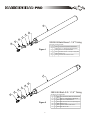
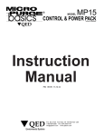
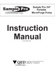
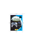
O
Field Service Manual
P/N 95211 REV 7-13-2006
Troubleshooting & Assistance Hot-Line
If you have questions or problems installing or
operating your HammerHead Pro system, Call
toll-free (in U.S and Canada) 1-800-624-2026
for expert assistance with installation, adjustment, or field service.
After hours call our 24 hour HotLine at
1-800-272-9559
P.O. Box 3726 Ann Arbor, MI 48106-3726 USA
1-800-624-2026 FAX (734) 995-1170
[email protected] www.qedenv.com
O
SAFETY
Safety has been a prime consideration when designing the AutoPump System. The AutoPump
System safety features are listed below. Please do not attempt to circumvent the safety features
of this system.
We have also listed some possible hazards involved when applying this system to site remediation.
Nothing will protect you as much as understanding the system, the site at which it is being used,
and the careful handling of all the equipment and fluids. If you have any questions, please contact
the QED Service Department for guidance.
A Partial List of Safety Procedures
These safety procedures should be followed at all times when operating QED equipment on or off
site, and should be considered as warnings:
WARNING: The air compressor and any other electrical equipment used with this pneumatic system must be positioned outside of any area considered hazardous because of
possible combustible materials.
Wear safety goggles when working with the AutoPump System to protect eyes from any
splashing or pressure release.
Wear chemically resistant rubber gloves, boots and coveralls when handling the AutoPump
and fluid discharge hose to avoid skin contact with the fluid being recovered.
Point all hoses away from personnel and equipment when connecting or disconnecting.
Always ensure that the fluid discharge hose is connected before the air hose to prevent
accidental discharge.
1
O
Pump Installation
1. Cover the pump tubing/hose ends with tape if they are to be pulled through trenches or laid on the
ground. This is to prevent debris from entering the lines.
2. Blow out all water and particles from compressed air conduits (including downwell pump air supply
lines) and fluid lines for at least 10 seconds after the water and particles exit before connecting
them to the system.
3. Slip clamps over appropriate tubing/hose prior to connecting the tubing/hose to the pump barbs.
4. Push tubing/hose down flush with the fitting's nut if possible; cover at least three barbs if three or
more are present (Note: when installing tubing in freezing weather, tubing can be dipped in warm
water for a few seconds to soften the nylon).
5. Attach pump support rope/cable to the pump.
6. Attach pump air supply and liquid discharge lines to the well cap. Attach the air exhaust line to the
well cap if the pump air is to exhaust outside the well (Note: the liquid discharge line is always the
largest diameter of the three lines, and the air supply line is always the smallest diameter).
7. Connect the pump air supply and liquid discharge lines to the appropriate surface lines/headers.
8. Turn on the air pressure to the pump (minimum of 0.5 psi per foot of vertical static head).
Caution: Submerging the pump before supplying it with air will result in fluid entering the
exhaust tubing/hose. Those fluids will be discharged from the exhaust tubing/hose during the
first few cycles of the pump. If this discharge will not be confined to the well; i.e., if the air
exhaust line is routed outside the well*, it is important to make sure that the air exhaust line is
not directed such that equipment/ personnel could be splashed by the discharged fluid when
air is turned on to the pump.
Note: Submerging the pump before supplying it with air can also result in fluid entering the air supply
line. This fluid from the well can contain particles, which could interfere with operation of the pump's
air valve.
9. Lower the pump to the desired depth in the well.
10. Secure the pump by tying off the pump support line or by placing the well cap (or flange) on the
well.
11. Increase the air pressure to the pump until the pump is pushing the fluid out at the desired rate.
With sufficient air pressure (at least 10 to 15 psi higher than the vertical static head), the pump will
gradually draw down the fluid level in the well to the level of the pump. The time required for this
draw down varies with the yield of the well as compared to the flow rate of the pump. The maximum recommended pump operating pressure is 120 psi.
2
O
Note: The Hammerhead-Pro pump can be submerged for long periods of time at most sites. If the
well environment is such that deposition occurs on stainless steel parts, the operator may wish to
raise the pump above the water level during a shutdown of the system.
* Routing the air exhaust in vacuum wells:
QED controllerless pumps ( i.e., AutoPumps and HammerHead Pumps) automatically control the
liquid level in the well. Under normal conditions, the liquid level will be maintained at a point approximately one foot below the top of a bottom load pump (this is the pump's actuation point). The pump
will automatically start and stop as needed to maintain the level at this actuation point.
When QED controllerless pumps are used in wells that are under vacuum, and the exhaust air is
routed into the well, the well level will be maintained at this normal actuation point. If, however, the
well is under vacuum and the exhaust air is routed outside of the well (to atmospheric pressure), the
actuation point of the pump will be higher than the normal actuation point by a distance equal to the
amount of vacuum applied to the well (expressed in "inches of water column"). Please note that the
pump will still function normally and maintain the liquid level, albeit a higher level.
3
O
Bottom Filling Pumps: Disassembly/Re-assembly for Cleaning
1. Unscrew the bottom inlet assembly
(counterclockwise) to remove it from
the pump casing.
2. Remove remaining internal pump
sub-assembly – grasp top of pump,
wiggle side to side and twist while
pulling out of pump casing.
3. All parts are now removed from pump.
Clean as necessary. Reverse the process
to reassemble the pump, starting with
STEP 4.
4. Slide internal pump assembly into pump
casing. O-ring should slide into casing.
NOTE: casing is universal – pump can slide
into either end. (See photo).
5. Screw bottom inlet assembly back into
pump casing and tighten.
6. Remove the barbed fitting from the top
check assembly. Remove the check ball.
Clean the check ball, check seat & barbed
fitting as necessary. Replace the check
ball. Replace the barbed fitting.
7. Tip pump over from top to bottom. You
should hear float sliding freely inside
body.
4
O
Top Filling Pumps: Disassembly/Re-assembly for Cleaning
1. Unscrew the bottom plug assembly
(counterclockwise) to remove it from
the pump casing.
2. Remove remaining internal pump subassembly – grasp top of pump, wiggle
side to side and twist while pulling out
of pump casing
3. All parts are now removed from pump.
Clean as necessary. Reverse the process
to reassemble the pump, starting with
STEP 4.
4. Slide internal pump assembly into pump
casing. The o-ring should slide into the
casing.
NOTE: the casing is universal – the pump
can slide into either end. (See photo).
5. Screw the bottom inlet assembly back
into the pump casing and tighten
6. Remove the barbed fitting from the
discharge check assembly. Remove the
check ball. Clean the check ball, check
seat & barbed fitting as necessary.
5
O
7. Remove the discharge check assembly
from the black wye fitting.
8. Remove the inlet screen assembly from
the black wye fitting.
9. Remove the inlet check ball. Clean the
check ball and seat as necessary.
10. Reassemble the inlet and discharge
check assemblies.
11. Tip the pump over from top to bottom.
You should hear the float sliding freely
inside the body.
Warning: The top fill inlet assembly (the
wye) is a relatively delicate component in
terms of assembly of the fittings. Over
tightening of the check assembly or other
fittings could result in leaks or even cause
the wye to split at the parting line.
6
O
1
3
4
7
5
6
38935 Kit Barb Brass 1-1/4" Tubing
2
Item No. Qty. Part No. Description
Figure 1
1
1
38931
Pump Sub-assembly Bottom Fill Base Model
2
1
38890
Barb 1" X 1" Mpt Discharge W/ Ball Stop Brass
3
1
39059
Barb 1/2" X 1/4" Mpt Exhaust Brass
4
1
38977
Barb W/air Check 3/8" X 1/4" Mpt Air Supply Brass
5
1
38807
Bracket "L" S.S.
6
1
38617
Connector, Chain 3/16" Dia. 316 S.S.
1
3
4
7
5
6
38936 Kit Barb S.S. 1-1/4" Tubing
2
Item No. Qty. Part No. Description
Figure 2
7
1
1
38933
Pump Sub-assembly Bottom Fill Leachate Model
2
1
38779
Barb 1" X 1" Mpt Discharge W/ Ball Stop S.S.
3
1
38874
Barb 1/2" X 1/4" Mpt Exhaust S.S.
4
1
38978
Barb, W/air Check 3/8" X 1/4" Mpt Air Supply S.S.
5
1
38807
Bracket "L" S.S.
6
1
38617
Connector, Chain 3/16" Dia. 316 S.S.
7
1
36936
Ball, Teflon 7/8" Dia.
O
1
3
4
7
5
38937 Kit Barb Brass 1" Tubing
6
Item No. Qty. Part No. Description
2
Figure 3
1
1
38931
Pump Sub-assembly Bottom Fill Base Model
2
1
38897
Barb 13/16 X 1" Mpt W/ Ball Stop Brass
3
1
39059
Barb 1/2" X 1/4" Mpt Exhaust Brass
4
1
38977
Barb W/air Check 3/8" X 1/4" Mpt Air Supply Brass
5
1
38807
Bracket "L" S.S.
6
1
38617
Connector, Chain 3/16" Dia. 316 S.S.
7
1
36936
Ball, Teflon 7/8" Dia.
1
3
4
7
38938 Kit Barb S.S. 1" Tubing
5
Item No. Qty. Part No. Description
6
2
Figure 4
8
1
1
38933
Pump Sub-assembly Bottom Fill Leachate Model
2
1
38880
Barb 13/16 X 1" Mpt W/ Ball Stop S.S.
3
1
38874
Barb 1/2" X 1/4" Mpt Exhaust S.S.
4
1
38978
Barb, W/air Check 3/8" X 1/4" Mpt Air Supply S.S.
5
1
38807
Bracket "L" S.S.
6
1
38617
Connector, Chain 3/16" Dia. 316 S.S.
7
1
36936
Ball, Teflon 7/8" Dia.
O
3
6
8
7
2
5
1
38932 Long Top-Loading
HammerHead Pro
4
9
No. Qty. Part No. Description
Figure 5
2
1
1 38869 Dip Tube 316 S.S.
2
3
1 38877 Bushing YOP Fill 1-5/16" UN X 1-1/4" UNEF S.S.
1 38930 Actuator Rod W/float Sub-Assembly
Head W/logo Sub-Assembly
4
1 38929
5
1 38902
Body Fiberglass 3" Pipe X 44" Long
6
1 38878
Inlet, Solid Top Fill Acetal
7
1 38900
O-Ring Viton 2-234
8
1 37227
Pipe Plug 1/4" Brass
9
1 38925
Inlet, Top Fill Base Model Sub-Assembly
3
4
6
1
38931 Long Bottom-Loading
HammerHead Pro
No. Qty. Part No. Description
Figure 6
7
5
9
Dip Tube 316 S.S.
1
1 38869
2
1 38867
Bushing1-5/16" UN X 1-1/4" UNEF S.S.
3
1 38923
Inlet, Bottom Base Model Sub-Assembly
4
1 38930
Actuator Rod W/float Sub-Assembly
5
1 38929
Head W/logo Sub-Assembly
6
1 38902
Body Fiberglass 3" Pipe X 44" Long
7
1 38889
Housing, Check1" MPTX 1" FPT Brass
O
3
2
4
38933 Long Bottom-Loading
Leachate HammerHead Pro
1
No. Qty. Part No. Description
6
Figure 7
5
7
2
1
1 38869 Dip Tube 316 S.S.
2
1 38867
Bushing1-5/16" UN X 1-1/4" UNEF S.S.
3
1 38924
Inlet, Bottom Base Model Sub-Assembly
4
1 38930
Actuator Rod W/float Sub-Assembly
5
1 38929
Head W/logo Sub-Assembly
6
1 38902
Body Fiberglass 3" Pipe X 44" Long
7
1 38870
Housing, Check1" MPTX 1" FPT 303 S.S.
3
4
1
6
39303 Short Bottom-Loading
HammerHead Pro
No. Qty. Part No. Description
7
5
Figure 8
10
1
1
39301 Dip Tube, Short 316 S.S.
2
1
38867 Bushing 1-5/16" UN x 1-1/4" UNEF S.S.
3
1
38923 Inlet, Bottom Base Model Sub-Assembly
4
1
39306 Actuator Rod, Short w/Float Sub-Assembly
5
1
38929 Head w/Logo Sub-Assembly
6
1
39300 Body, Short Fiberglass 3" Pipe x 32.25" Long
7
1
38889 Housing, Check 1" MPT x 1" FPT Brass
O
9
5
7
6
2
1
4
39304 Short Top-Loading
HammerHead Pro
3
8
Figure 9
Item No.
1
2
3
4
5
6
7
8
9
Qty. Part No.
1
39301
1
38877
1
38929
1
39300
1
38878
1
38900
1
37227
1
38925
1
39306
Description
Dip Tube, Short 316 S.S.
Bushing Yop Fill 1-5/16"un X 1-1/4"unef S.S.
Head W/logo Sub-assembly
Body, Short Fiberglass 3" Pipe X 32.25" Long
Inlet, Solid Top Fill Acetal
O-ring Viton 2-234
Pipe Plug 1/4" Brass
Inlet, Top Fill Base Model Sub-assembly
Actuator Rod, Short W/float Sub-assembly
3
7
2
1
5
39305 Short Bottom-Loading
HammerHead Pro
6
4
Figure 10
11
Item No.
1
2
3
4
5
6
7
Qty.
1
1
1
1
1
1
1
Part No.
39301
38867
38924
38929
39300
38870
39306
Description
Dip Tube, Short 316 S.S.
Bushing 1-5/16" Un X 1-1/4" Unef S.S.
Inlet, Bottom Base Model Sub-assembly
Head W/logo Sub-assembly
Body, Short Fiberglass 3" Pipe X 32.25" Long
Housing, Check 1" Mpt X 1" Fpt 303 S.S.
Actuator Rod, Short W/float Sub-assembly
O
8
8
6
8
7
6
4
6
3
2
1
8
7
9
10
8
7
8
5
38923 Bottom Inlet
HammerHead Pro
3
3
Item No. Qty. Part No. Description
9
Figure 11
9
5
11
4
7
1
1
38909 Collar Acetal
2
1
38908 Plug UHMW-PE
3
3
38911
4
1
38910 Seat, Inlet UHMW-PE
5
1
38913 Screen, Inlet
6
3
38903 Nut Acorn Hex. 1/4" -20 UNC S.S.
7
3
38905 Locknut Hex Nylon Insert 1/4"-20 UNC S.S.
8
6
38904 Washer Lock 1/4" S.S.
9
3
38906 Screw Hex. Hd. Cap 1/4"-20 UNC x 5" Lg. S.S.
10
1
38900 O-Ring Viton 2-234
8
6
6
8
6
10
8
3
2
1
11
9
3
7
11
8
8
8
7
38924 Bottom Inlet Leachate
HammerHead Pro
Item No. Qty. Part No. Description
3
9
9
Sleeve, Bolt Bottom Check
Figure 12
12
1
1
38909
Collar Acetal
2
1
38908
Plug UHMW-PE
3
3
38911
Sleeve, Bolt Bottom Check
4
1
38910
Seat, Inlet UHMW-PE
5
1
38914
Screen Intake 3" S.S.
6
3
38903
Nut Acorn Hex. 1/4" -20UNC S.S,
7
3
38905
Locknut Hex Nylon Insert 1/4"-20UNC S.S,
8
6
38904
Washer Lock 1/4" S.S,
9
3
38907
Screw Hex. Hd. Cap 1/4"-20UNC x 8" Lg. S.S,
10
1
38900
O-Ring Viton 2-234
11
3
38912
Sleeve Basket 3" S.S,
O
6
8
5
7
6
8
6
11
4
8
10
8
3
8
2
8
1
7
7
11
9
3
11
Figure 13
3
9
39842 Stainless Steel Inlet Kit
Item No. Qty.Part No.
1 39833
1
1 39834
2
3 39835
3
1 39836
4
1 39837
5
3 39838
6
3 39839
7
6 37241
8
3 39841
9
1 38900
10
3 38912
11
Description
Collar, Bcv 316 S.S.
Plug, Bcv Intake Ptfe
Sleeve, Bolt Bottom Check 316 S.S.
Seat, Inlet 316 S.S.
Screen Intake 3" S.S. 316 S.S.
Nut Acorn Hex. 1/4" -20 Unc 316 S.S.
Locknut Hex Nylon Insert 1/4"-20unc 316 S.S.
Washer, Lock 1/4" S.S.
Screw Hex. Hd. Cap 1/4"-20unc X 8" Lg. 316 S.S.
O-ring Viton 2-234
Sleeve Basket 3" S.S.
9
3
2
4
1
6
Figure 14
7
5
39844 S.S. Bottom-Loading
HammerHead Pro
Item No.
1
2
3
4
5
6
Qty. Part No.
1
38869
1
38867
1
39842
1
39843
1
38929
1
39555ep
Description
Dip Tube S.S.
Bushing 1-5/16" Un X 1-1/4" Unef S.S.
Inlet, Bottom Base Model Sub-assembly 316 S.S.
Actuator Rod W/s.s. Float Assembly
Head W/logo Sub-assembly
Casing, S.S. Electro-polished
4
6
2
3
38925 Inlet Top-Fill
HammerHead Pro
5
Item No. Qty. Part No. Description
Figure 15
1
13
1
1
38915 Nipple Assembly S.S,
2
1
38921 Seat Fluid Inlet Top Fill Brass
3
1
38919 Ball, Teflon 1" Dia.
4
1
37164 Screen Top Fill Nylon
5
1
38920 Wye Molded With Pin
6
1
38889 Housing, Check 1" MPT x 1" FPT Brass
O
6
1
5
38929 Head Assembly Top-Fill
HammerHead Pro
7
8
Item No. Qty. Part No.
10
2
3
9
10
4
Figure 16
1
1
2
1
3
1
4
1
5
1
6
1
7
1
8
1
9
1
10
2
Description
38918
Head w/ Logo S.S.
38746
Bracket S.S,
38801
Screw, Soc. Button Hd. 1/4"-20UNC x 1 3/4" Lg. S.S,
38900
O-Ring Viton 2-234
38941
Magnet Holder Sub-Assembly
38798
Screw, Set #8-32 x 1/4" Lg. S.S,
38927
Exhaust Seat Sub-Assembly
38926
Air Seat Sub-Assembly
38928
Cam Sub-Assembly
36821
Pin, Spring 1/8" Dia. X 1/2" Lg. S.S,
HammerHead Pro
Cam Sub-Assembly
(Part # 38928)
Figure 17
14
O
Terms, Conditions, and Warranty
QED Environmental Systems, Inc. (QED) warrants to the original purchaser of its products that, subject to the limitations and conditions
provided below, the products, materials and/or workmanship shall reasonably conform to descriptions of the products and shall be free
of defects in materials and workmanship. Any failure of the products to conform to this warranty will be remedied by QED in the manner
provided herein
This warranty shall be limited to the duration and the conditions set forth below. All warranty durations are calculated from the original
date of purchase.
1. AP-4 AutoPumps (Long and Short lengths; Top- and Bottom-Inlets) warranted for five (5) years:100% material and 100%
workmanship for the first three (3) years; 50% material and 50% workmanship for the fourth (4th) and fifth (5th) years. AP-4 Lowdrawdown AutoPumps warranted for one (1) year: 100% material and 100% workmanship.
2. HammerHead Pro Pumps (Top- and Bottom-Inlets) warranted for three (3) years: 100% material and 100% workmanship.
3. AP-3 AutoPumps (Long and Short lengths; Top- and Bottom-Inlets) warranted for two (2) years: 100% material and 100%
workmanship.
4. AP-2 AutoPumps (Long and Short lengths; Top- and Bottom-Inlets) warranted for one (1) year: 100% material and 100%
workmanship.
5. Hoses, Tubing, Fittings, Well Caps and Flanges warranted for one (1) year: 100% material and 100% workmanship.
6. Pneumatic Data Modules / Logic Control Panels warranted for one (1) year: 100% material and 100% workmanship.
7. Parts and Repairs warranted for ninety (90) days: 100% material and 100% workmanship; when repairs are performed by QED or
its appointed agent; from date of repair or for the full term of the original warranty, whichever is longer. Separately sold parts are
warranted for ninety (90) days: 100% materials and 100% workmanship.
Buyer's Remedy
Buyer's exclusive remedy for breach of said warranty shall be as follows: if, and only if, QED is notified in writing within the applicable
warranty period of the existence of any such defects in the said products, and QED upon examination of any such defects, shall find the
same to be within the term of and covered by the warranty running from QED to buyer, QED will, at its option, as soon as reasonably
possible, replace or repair any such product, without charge to the buyer. If QED for any reason, cannot repair a product covered hereby
then QED's sole responsibility shall be, at its option, to either replace the defective product with a comparable new unit at no charge to
the buyer, or to refund the full purchase price. If the product proves not to be defective within the terms of this warranty, then all costs
and expenses in connection with the processing of the purchaser's claim and all costs for repair, parts and labor as authorized by owner
hereunder shall be borne by the Purchaser.
WARRANTY CLAIMS PROCEDURE (RESPONSIBILITY OF PURCHASER)
The original purchaser's sole responsibility in the instance of a warranty claim shall be to notify QED or its appointed agent, of the
defect, malfunction, or other manner in which the terms of this warranty are believed to be violated. The purchaser may secure performance of obligations hereunder by contacting the Customer Service Department of QED or its appointed agent, and:
1. Identifying the product involved by model or serial number, or other sufficient description, that will allow QED, or its appointed agent,
to determine which product is defective.
2. Specifying where, when, and from whom the product was purchased.
3. Describing the nature of the defect or malfunction covered by this warranty.
4. After obtaining authorization from QED, sending the malfunctioning component via a RMA# (Return Material Authorization number) to
the address provided at that time.
In no event shall such allegedly defective products be returned to QED without its consent, and QED's obligations of repair, replacement
or refund are conditioned upon the Buyer's return of the defective product to QED.
QED shall be released from all obligations under all warranties if any product covered hereby is repaired or modified by persons other
than QED's service personnel unless such repair by others is made with the written consent of QED
The foregoing warranty does not apply to major subassemblies and other equipment, accessories, and other parts manufactured by
others, and such other parts, accessories, and equipment are subject only to the warranties, if any, supplied by their respective manufacturers. QED makes no warranty concerning products or accessories not manufactured by QED. In the event of failure of any such
product or accessory, QED will give reasonable assistance to Buyer in obtaining from the respective manufacturer whatever adjustment
is reasonable in light of the manufacturer's own warranty.
15
O
Terms, Conditions, and Warranty
THE FOREGOING WARRANTY IS IN LIEU OF ALL OTHER WARRANTIES, EXPRESSED, IMPLIED OR STATUTORY (INCLUDING
BUT NOT LIMITED TO THE WARRANTIES OF MERCHANTABILITYAND FITNESS FOR A PARTICULAR PURPOSE), WHICH
OTHER WARRANTIES ARE EXPRESSLY EXCLUDED HEREBY, and of any other obligations or liabilities on the part of QED, and QED
neither assumes nor authorizes any person to assume for it any other obligation or liability in connection with said products, materials
and/or workmanship. It is understood and agreed that QED shall in no event be liable for incidental or consequential damages resulting
from its breach of any of the terms of this agreement, nor for special damages, nor for improper selection of any product described or
referred to for a particular application.
This warranty will be void in the event of unauthorized disassembly of component assemblies. Defects in any equipment that result from
abuse, operation in any manner outside the recommended specifications, procedures, use and applications other than for intended use,
or exposure to chemical or physical environment beyond the designated limits of materials and construction will also void this warranty.
Chemical attack of liquid contacting equipment and supplies shall not be covered by this warranty. A range of materials is available from
QED and it is the Buyer's responsibility to select materials to fit the Buyer's application. QED will only warrant that the supplied liquid
contacting materials will conform to published QED specifications and generally accepted standards for that particular material.
ILLUSTRATIONS AND DRAWINGS
Reasonable Effort has been made to have all illustrations and drawings accurately represent the product(s) as it actually was at the time
of doing the illustrations and drawings.
However, products may change to meet user requirements and therefore may not be reflected in the literature. In addition, literature
may be up-dated to reflect the most recent equipment revision(s). Changes to either or both equipment and/or literature can be made
without notice.
CHANGES WITHOUT NOTICE
Prices and Specifications are subject to change without notice.
SHIPPING DATES
Shipping dates are approximate and are subject to delays beyond our control.
F.O.B. POINT AND TITLE
All material is sold F.O.B. factory. Title to all merchandise sold shall pass to Buyer upon delivery by Seller to carrier at factory. All freight
insurance is the responsibility of the Buyer and shall be charged to the Buyer on the invoice unless directed in writing. All Freight claims
are the Buyer's responsibility.
TERMS
Payment terms are net 30 days; 1.5% per month past due.
STATE AND LOCAL TAXES
Any taxes, duties or fees which the seller may be required to pay or collect upon or with respect to the sale, purchase, delivery, use or
consumption of any of the material covered hereby shall be for the account of the Buyer and shall be added to the purchase price.
ACCEPTANCE
All orders shall be subject to the terms and conditions contained or referred to in the Seller's quotation, acknowledgments, and to those
listed here and to no others whatsoever. No waiver, alteration or modification of these terms and conditions shall be binding unless in
writing and signed by an executive officer of the Seller. All orders subject to written acceptance by QED Environmental Systems Inc.,
Ann Arbor, MI, U.S.A.
QED ENVIRONMENTAL SYSTEMS INC.
6155 Jackson Rd.
Ann Arbor, MI 48103
USA
(800) 624-2026 Toll-Free in North America
(734) 995-2547
(734) 995-1170 FAX
www.qedenv.com
16