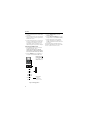
1
MAGNUM+
TK 60275-4-MM (Rev. 0, 09/08)
Copyright© 2008 Ingersoll Rand Climate Control Technologies - European Served Area
Printed in Ireland
2
The maintenance information in this manual covers unit models:
Base Unit
MAGNUM+
098203
For further information, refer to:
Parts Manuals
MAGNUM Parts List
TK 54356
Operation, Diagnosis and Refrigeration Maintenance Manuals
Diagnosing Thermo King Container Refrigeration Systems
TK 41166
Electrostatic Discharge (ESD) Training Guide
TK 40282
Evacuation Station Operation and Field Application
TK 40612
Tool Catalog
TK 5955
The information in this manual is provided to assist owners, operators and service people in the proper
upkeep and maintenance of Thermo King units.
This manual is published strictly for informational purposes. The information so provided should
not be considered as all-inclusive or covering all contingencies. Thermo King Corporation
should be consulted if further information is required.
Sale of product shown in this manual is subject to Thermo King’s terms and conditions.
This includes, but not limited to, the Thermo King Limited Express Warranty. Such terms
and conditions are available upon request. Thermo King’s warranty will not apply to any
equipment which has been “so repaired or altered outside the manufacturer’s plants as,
in the manufacturer’s judgment, to effect its stability.”
No warranties, express or implied, are made regarding the information,
recommendations, and descriptions contained herein. This includes warranties of
fitness for a particular purpose or merchantability, or warranties arising from course of
dealing or usage of trade. The manufacturer is not responsible and will not be held liable
in contract or in tort (including negligence) for any special, indirect or consequential
damages. This includes injury or damage caused to vehicles, contents or persons, by
reason of the installation of any Thermo King product or its mechanical failure.
Recover Refrigerant
At Thermo King, we recognize the need to preserve the environment
and limit the potential harm to the ozone layer that can result from
allowing refrigerant to escape into the atmosphere.
We strictly adhere to a policy that promotes the recovery and limits
the loss of refrigerant into the atmosphere.
In addition, service personnel must be aware of Federal regulations
concerning the use of refrigerants and the certification of technicians.
For additional information on regulations and technician certification
programs, contact your local Thermo King dealer.
R-404A
WARNING: Use only Polyol Ester-based refrigeration compressor oil in
R-404A. See Thermo King Parts Manual for part number.
Do not mix Polyol Ester and standard synthetic compressor oils. Keep Polyol
Ester compressor oil in tightly sealed containers. If Polyol Ester oil becomes
contaminated with moisture or standard oils, dispose of properly–DO NOT USE.
When servicing Thermo King R-404A unit, use only those service tools certified
for and dedicated to R-404A refrigerant and Polyol Ester compressor oils.
Residual non-HFX refrigerants or oils will contaminate R-404A systems.
Table of Contents
List Of Figures . . . . . . . . . . . . . . . . . . . . . . . . . . . . . . . . . . . . . . . . . . . . . . . . . . . . . . . . . . . . . . . . . . . . . . . . . . . 9
Safety Instructions . . . . . . . . . . . . . . . . . . . . . . . . . . . . . . . . . . . . . . . . . . . . . . . . . . . . . . . . . . . . . . . . . . . . . . 11
General Precautions . . . . . . . . . . . . . . . . . . . . . . . . . . . . . . . . . . . . . . . . . . . . . . . . . . . . . . . . . . . . . . . . . . . . . . 11
Refrigerant Oil Precautions . . . . . . . . . . . . . . . . . . . . . . . . . . . . . . . . . . . . . . . . . . . . . . . . . . . . . . . . . . . . . . . . . 11
Electrical Precautions . . . . . . . . . . . . . . . . . . . . . . . . . . . . . . . . . . . . . . . . . . . . . . . . . . . . . . . . . . . . . . . . . . . . . 11
Precautions . . . . . . . . . . . . . . . . . . . . . . . . . . . . . . . . . . . . . . . . . . . . . . . . . . . . . . . . . . . . . . . . . . . . . . . . . . 11
First Aid . . . . . . . . . . . . . . . . . . . . . . . . . . . . . . . . . . . . . . . . . . . . . . . . . . . . . . . . . . . . . . . . . . . . . . . . . . . . 12
Low Voltage . . . . . . . . . . . . . . . . . . . . . . . . . . . . . . . . . . . . . . . . . . . . . . . . . . . . . . . . . . . . . . . . . . . . . . . . . 12
Electrostatic Discharge Precautions . . . . . . . . . . . . . . . . . . . . . . . . . . . . . . . . . . . . . . . . . . . . . . . . . . . . . . . . . . 12
Electrostatic Discharge and the Controller . . . . . . . . . . . . . . . . . . . . . . . . . . . . . . . . . . . . . . . . . . . . . . . . . . 12
Welding of Units or Containers . . . . . . . . . . . . . . . . . . . . . . . . . . . . . . . . . . . . . . . . . . . . . . . . . . . . . . . . . . . 13
Removing Refrigerant Properly . . . . . . . . . . . . . . . . . . . . . . . . . . . . . . . . . . . . . . . . . . . . . . . . . . . . . . . . . . . . . . 13
Identifying Unit Safety and Warning Decals . . . . . . . . . . . . . . . . . . . . . . . . . . . . . . . . . . . . . . . . . . . . . . . . . . . . 15
Locating Serial Numbers . . . . . . . . . . . . . . . . . . . . . . . . . . . . . . . . . . . . . . . . . . . . . . . . . . . . . . . . . . . . . . . . . . . 15
Service Guide . . . . . . . . . . . . . . . . . . . . . . . . . . . . . . . . . . . . . . . . . . . . . . . . . . . . . . . . . . . . . . . . . . . . . . . . . . 17
Service Guide . . . . . . . . . . . . . . . . . . . . . . . . . . . . . . . . . . . . . . . . . . . . . . . . . . . . . . . . . . . . . . . . . . . . . . . . . . . 17
Specifications . . . . . . . . . . . . . . . . . . . . . . . . . . . . . . . . . . . . . . . . . . . . . . . . . . . . . . . . . . . . . . . . . . . . . . . . . . 19
Evaporator Airflow Specifications . . . . . . . . . . . . . . . . . . . . . . . . . . . . . . . . . . . . . . . . . . . . . . . . . . . . . . . . . . . . 19
Electrical System Specifications . . . . . . . . . . . . . . . . . . . . . . . . . . . . . . . . . . . . . . . . . . . . . . . . . . . . . . . . . . . . . 19
Refrigeration System Specifications . . . . . . . . . . . . . . . . . . . . . . . . . . . . . . . . . . . . . . . . . . . . . . . . . . . . . . . . . . 20
Unit Description, Features & Options . . . . . . . . . . . . . . . . . . . . . . . . . . . . . . . . . . . . . . . . . . . . . . . . . . . . . . . 25
Introduction . . . . . . . . . . . . . . . . . . . . . . . . . . . . . . . . . . . . . . . . . . . . . . . . . . . . . . . . . . . . . . . . . . . . . . . . . . . . . 25
General Description . . . . . . . . . . . . . . . . . . . . . . . . . . . . . . . . . . . . . . . . . . . . . . . . . . . . . . . . . . . . . . . . . . . 25
Scroll Compressor . . . . . . . . . . . . . . . . . . . . . . . . . . . . . . . . . . . . . . . . . . . . . . . . . . . . . . . . . . . . . . . . . . . . . . . 26
MP-4000 Controller . . . . . . . . . . . . . . . . . . . . . . . . . . . . . . . . . . . . . . . . . . . . . . . . . . . . . . . . . . . . . . . . . . . . . . . 26
Compressor Digital Control Valve . . . . . . . . . . . . . . . . . . . . . . . . . . . . . . . . . . . . . . . . . . . . . . . . . . . . . . . . . . . . 26
Economizer Heat Exchange System . . . . . . . . . . . . . . . . . . . . . . . . . . . . . . . . . . . . . . . . . . . . . . . . . . . . . . . . . 27
Temperature Sensors . . . . . . . . . . . . . . . . . . . . . . . . . . . . . . . . . . . . . . . . . . . . . . . . . . . . . . . . . . . . . . . . . . . . . 27
Fresh Air Exchange System . . . . . . . . . . . . . . . . . . . . . . . . . . . . . . . . . . . . . . . . . . . . . . . . . . . . . . . . . . . . . . . . 27
Fresh Air Exchange Recorder (Optional) . . . . . . . . . . . . . . . . . . . . . . . . . . . . . . . . . . . . . . . . . . . . . . . . . . . . . . 27
Receiver Tank Sight Glass . . . . . . . . . . . . . . . . . . . . . . . . . . . . . . . . . . . . . . . . . . . . . . . . . . . . . . . . . . . . . . . . 28
Evaporator Fans . . . . . . . . . . . . . . . . . . . . . . . . . . . . . . . . . . . . . . . . . . . . . . . . . . . . . . . . . . . . . . . . . . . . . . . . . 28
Condenser Fan Control . . . . . . . . . . . . . . . . . . . . . . . . . . . . . . . . . . . . . . . . . . . . . . . . . . . . . . . . . . . . . . . . . . . . 28
Unit Options . . . . . . . . . . . . . . . . . . . . . . . . . . . . . . . . . . . . . . . . . . . . . . . . . . . . . . . . . . . . . . . . . . . . . . . . . . . . 29
Recording Thermometer (Optional) . . . . . . . . . . . . . . . . . . . . . . . . . . . . . . . . . . . . . . . . . . . . . . . . . . . . . . . 29
Remote Monitoring Modem (RMM) (Optional) . . . . . . . . . . . . . . . . . . . . . . . . . . . . . . . . . . . . . . . . . . . . . . . 29
Suction and Discharge Pressure Sensors (Optional) . . . . . . . . . . . . . . . . . . . . . . . . . . . . . . . . . . . . . . . . . . 29
Air Ventilation Logging (AVL - Optional) . . . . . . . . . . . . . . . . . . . . . . . . . . . . . . . . . . . . . . . . . . . . . . . . . . . . 29
USDA Cold Treatment Temperature Recording (standard) . . . . . . . . . . . . . . . . . . . . . . . . . . . . . . . . . . . . . 30
Water-Cooled Condenser/Receiver Tank (Optional) . . . . . . . . . . . . . . . . . . . . . . . . . . . . . . . . . . . . . . . . . . 30
Water Pressure Switch (Optional) . . . . . . . . . . . . . . . . . . . . . . . . . . . . . . . . . . . . . . . . . . . . . . . . . . . . . . . . 30
Controller Description . . . . . . . . . . . . . . . . . . . . . . . . . . . . . . . . . . . . . . . . . . . . . . . . . . . . . . . . . . . . . . . . . . . 37
Controller Description . . . . . . . . . . . . . . . . . . . . . . . . . . . . . . . . . . . . . . . . . . . . . . . . . . . . . . . . . . . . . . . . . . . . . 37
Controller Back-up Battery . . . . . . . . . . . . . . . . . . . . . . . . . . . . . . . . . . . . . . . . . . . . . . . . . . . . . . . . . . . . . . 37
Controller Input and Output Signals . . . . . . . . . . . . . . . . . . . . . . . . . . . . . . . . . . . . . . . . . . . . . . . . . . . . . . . 37
Standard Display . . . . . . . . . . . . . . . . . . . . . . . . . . . . . . . . . . . . . . . . . . . . . . . . . . . . . . . . . . . . . . . . . . . . . . . . . 38
Glossary of Mode Descriptions . . . . . . . . . . . . . . . . . . . . . . . . . . . . . . . . . . . . . . . . . . . . . . . . . . . . . . . . . . . 39
Function Keys . . . . . . . . . . . . . . . . . . . . . . . . . . . . . . . . . . . . . . . . . . . . . . . . . . . . . . . . . . . . . . . . . . . . . . . . . . . 40
Three Special Function Keys . . . . . . . . . . . . . . . . . . . . . . . . . . . . . . . . . . . . . . . . . . . . . . . . . . . . . . . . . . . . . . . 40
Operating Instructions . . . . . . . . . . . . . . . . . . . . . . . . . . . . . . . . . . . . . . . . . . . . . . . . . . . . . . . . . . . . . . . . . . . 41
Function Keys . . . . . . . . . . . . . . . . . . . . . . . . . . . . . . . . . . . . . . . . . . . . . . . . . . . . . . . . . . . . . . . . . . . . . . . . . . . 41
Unit On/Off Key . . . . . . . . . . . . . . . . . . . . . . . . . . . . . . . . . . . . . . . . . . . . . . . . . . . . . . . . . . . . . . . . . . . . . . . . . . 41
Sequence Of Operation . . . . . . . . . . . . . . . . . . . . . . . . . . . . . . . . . . . . . . . . . . . . . . . . . . . . . . . . . . . . . . . . . . . 41
Unit Start-up . . . . . . . . . . . . . . . . . . . . . . . . . . . . . . . . . . . . . . . . . . . . . . . . . . . . . . . . . . . . . . . . . . . . . . . . . 41
Viewing Alarms/Warnings . . . . . . . . . . . . . . . . . . . . . . . . . . . . . . . . . . . . . . . . . . . . . . . . . . . . . . . . . . . . . . . 43
Display Alternate Fahrenheit (F) or Celsius (C) Temperatures . . . . . . . . . . . . . . . . . . . . . . . . . . . . . . . . . . 43
5
Table of Contents
Changing Setpoint . . . . . . . . . . . . . . . . . . . . . . . . . . . . . . . . . . . . . . . . . . . . . . . . . . . . . . . . . . . . . . . . . . . . 43
Controller Back-up Battery . . . . . . . . . . . . . . . . . . . . . . . . . . . . . . . . . . . . . . . . . . . . . . . . . . . . . . . . . . . . . . 43
Navigating the Controller Operating Menu . . . . . . . . . . . . . . . . . . . . . . . . . . . . . . . . . . . . . . . . . . . . . . . . . . . 45
Navigating the Controller Operating Menu . . . . . . . . . . . . . . . . . . . . . . . . . . . . . . . . . . . . . . . . . . . . . . . . . . . . . 45
Menu Scrolling Keys . . . . . . . . . . . . . . . . . . . . . . . . . . . . . . . . . . . . . . . . . . . . . . . . . . . . . . . . . . . . . . . . . . . 45
Main Menu . . . . . . . . . . . . . . . . . . . . . . . . . . . . . . . . . . . . . . . . . . . . . . . . . . . . . . . . . . . . . . . . . . . . . . . . . . . . . 47
Data Menu . . . . . . . . . . . . . . . . . . . . . . . . . . . . . . . . . . . . . . . . . . . . . . . . . . . . . . . . . . . . . . . . . . . . . . . . . . . . . . 47
Viewing the Data Menu . . . . . . . . . . . . . . . . . . . . . . . . . . . . . . . . . . . . . . . . . . . . . . . . . . . . . . . . . . . . . . . . . 47
Setpoint Menu . . . . . . . . . . . . . . . . . . . . . . . . . . . . . . . . . . . . . . . . . . . . . . . . . . . . . . . . . . . . . . . . . . . . . . . . . . . 47
Temperature Setpoint . . . . . . . . . . . . . . . . . . . . . . . . . . . . . . . . . . . . . . . . . . . . . . . . . . . . . . . . . . . . . . . . . . 47
Controlling Modes . . . . . . . . . . . . . . . . . . . . . . . . . . . . . . . . . . . . . . . . . . . . . . . . . . . . . . . . . . . . . . . . . . . . . 48
Change the Humidity Control Setting . . . . . . . . . . . . . . . . . . . . . . . . . . . . . . . . . . . . . . . . . . . . . . . . . . . . . . 48
Change the Humidity Setpoint . . . . . . . . . . . . . . . . . . . . . . . . . . . . . . . . . . . . . . . . . . . . . . . . . . . . . . . . . . . 48
Commands Menu . . . . . . . . . . . . . . . . . . . . . . . . . . . . . . . . . . . . . . . . . . . . . . . . . . . . . . . . . . . . . . . . . . . . . . . . 49
View the Commands Menu . . . . . . . . . . . . . . . . . . . . . . . . . . . . . . . . . . . . . . . . . . . . . . . . . . . . . . . . . . . . . . 49
PTI, Brief PTI, Function Test Display . . . . . . . . . . . . . . . . . . . . . . . . . . . . . . . . . . . . . . . . . . . . . . . . . . . . . . 49
PTI (Pretrip) Test . . . . . . . . . . . . . . . . . . . . . . . . . . . . . . . . . . . . . . . . . . . . . . . . . . . . . . . . . . . . . . . . . . . . . . . . . 50
Brief PTI (Pretrip) Test . . . . . . . . . . . . . . . . . . . . . . . . . . . . . . . . . . . . . . . . . . . . . . . . . . . . . . . . . . . . . . . . . 50
Function Test . . . . . . . . . . . . . . . . . . . . . . . . . . . . . . . . . . . . . . . . . . . . . . . . . . . . . . . . . . . . . . . . . . . . . . . . . . . . 51
Manual Function Test . . . . . . . . . . . . . . . . . . . . . . . . . . . . . . . . . . . . . . . . . . . . . . . . . . . . . . . . . . . . . . . . . . 52
Defrost . . . . . . . . . . . . . . . . . . . . . . . . . . . . . . . . . . . . . . . . . . . . . . . . . . . . . . . . . . . . . . . . . . . . . . . . . . . . . . . . . 61
Trip Start . . . . . . . . . . . . . . . . . . . . . . . . . . . . . . . . . . . . . . . . . . . . . . . . . . . . . . . . . . . . . . . . . . . . . . . . . . . . 61
Alarms/Warnings Menu . . . . . . . . . . . . . . . . . . . . . . . . . . . . . . . . . . . . . . . . . . . . . . . . . . . . . . . . . . . . . . . . . . . . 62
Alarm Code States . . . . . . . . . . . . . . . . . . . . . . . . . . . . . . . . . . . . . . . . . . . . . . . . . . . . . . . . . . . . . . . . . . . . . . . 62
Alarm/Warning List Menu . . . . . . . . . . . . . . . . . . . . . . . . . . . . . . . . . . . . . . . . . . . . . . . . . . . . . . . . . . . . . . . . . . 63
View the Alarm/Warning List Menu . . . . . . . . . . . . . . . . . . . . . . . . . . . . . . . . . . . . . . . . . . . . . . . . . . . . . . . . 63
Warning List Menu . . . . . . . . . . . . . . . . . . . . . . . . . . . . . . . . . . . . . . . . . . . . . . . . . . . . . . . . . . . . . . . . . . . . 64
Alarm List Menu . . . . . . . . . . . . . . . . . . . . . . . . . . . . . . . . . . . . . . . . . . . . . . . . . . . . . . . . . . . . . . . . . . . . . . 64
Configuration Menu . . . . . . . . . . . . . . . . . . . . . . . . . . . . . . . . . . . . . . . . . . . . . . . . . . . . . . . . . . . . . . . . . . . . . . . 65
Viewing or Setting Functions . . . . . . . . . . . . . . . . . . . . . . . . . . . . . . . . . . . . . . . . . . . . . . . . . . . . . . . . . . . . 65
Set Date and Time . . . . . . . . . . . . . . . . . . . . . . . . . . . . . . . . . . . . . . . . . . . . . . . . . . . . . . . . . . . . . . . . . . . . 66
Datalogger Menu . . . . . . . . . . . . . . . . . . . . . . . . . . . . . . . . . . . . . . . . . . . . . . . . . . . . . . . . . . . . . . . . . . . . . . . . . 66
Viewing the Datalogger Menu . . . . . . . . . . . . . . . . . . . . . . . . . . . . . . . . . . . . . . . . . . . . . . . . . . . . . . . . . . . . 67
Inspect Log . . . . . . . . . . . . . . . . . . . . . . . . . . . . . . . . . . . . . . . . . . . . . . . . . . . . . . . . . . . . . . . . . . . . . . . . . . 67
Calibrate Probe (Optional) . . . . . . . . . . . . . . . . . . . . . . . . . . . . . . . . . . . . . . . . . . . . . . . . . . . . . . . . . . . . . . 67
Set Log Time Interval . . . . . . . . . . . . . . . . . . . . . . . . . . . . . . . . . . . . . . . . . . . . . . . . . . . . . . . . . . . . . . . . . . 69
States Menu . . . . . . . . . . . . . . . . . . . . . . . . . . . . . . . . . . . . . . . . . . . . . . . . . . . . . . . . . . . . . . . . . . . . . . . . . . . . 70
PTI . . . . . . . . . . . . . . . . . . . . . . . . . . . . . . . . . . . . . . . . . . . . . . . . . . . . . . . . . . . . . . . . . . . . . . . . . . . . . . . . 70
Input - Output . . . . . . . . . . . . . . . . . . . . . . . . . . . . . . . . . . . . . . . . . . . . . . . . . . . . . . . . . . . . . . . . . . . . . . . . 70
RMM State . . . . . . . . . . . . . . . . . . . . . . . . . . . . . . . . . . . . . . . . . . . . . . . . . . . . . . . . . . . . . . . . . . . . . . . . . . 70
Viewing the RMM State Screen . . . . . . . . . . . . . . . . . . . . . . . . . . . . . . . . . . . . . . . . . . . . . . . . . . . . . . . . . . 70
Operating Theory . . . . . . . . . . . . . . . . . . . . . . . . . . . . . . . . . . . . . . . . . . . . . . . . . . . . . . . . . . . . . . . . . . . . . . . . 73
Chill Loads: (Setpoint at -9.9 C [14.1 F] and Above) . . . . . . . . . . . . . . . . . . . . . . . . . . . . . . . . . . . . . . . . . . 73
Frozen Loads: (Setpoint at -10 C [14 F] and Below) . . . . . . . . . . . . . . . . . . . . . . . . . . . . . . . . . . . . . . . . . . . 73
Compressor Vapor Injection . . . . . . . . . . . . . . . . . . . . . . . . . . . . . . . . . . . . . . . . . . . . . . . . . . . . . . . . . . . . . 73
High Temperature Protection . . . . . . . . . . . . . . . . . . . . . . . . . . . . . . . . . . . . . . . . . . . . . . . . . . . . . . . . . . . . 73
Power Limit Mode . . . . . . . . . . . . . . . . . . . . . . . . . . . . . . . . . . . . . . . . . . . . . . . . . . . . . . . . . . . . . . . . . . . . . 74
Evaporator Fan Control . . . . . . . . . . . . . . . . . . . . . . . . . . . . . . . . . . . . . . . . . . . . . . . . . . . . . . . . . . . . . . . . . 74
Condenser Fan Control . . . . . . . . . . . . . . . . . . . . . . . . . . . . . . . . . . . . . . . . . . . . . . . . . . . . . . . . . . . . . . . . . 74
Probe Test . . . . . . . . . . . . . . . . . . . . . . . . . . . . . . . . . . . . . . . . . . . . . . . . . . . . . . . . . . . . . . . . . . . . . . . . . . 74
Dehumidify Mode . . . . . . . . . . . . . . . . . . . . . . . . . . . . . . . . . . . . . . . . . . . . . . . . . . . . . . . . . . . . . . . . . . . . . 74
Continuous Temperature Control Operation . . . . . . . . . . . . . . . . . . . . . . . . . . . . . . . . . . . . . . . . . . . . . . . . . . . . 75
Frozen Loads (Controller Setpoint at -10 C [14 F] and Below): . . . . . . . . . . . . . . . . . . . . . . . . . . . . . . . . . . 77
Compressor Digital Control Valve . . . . . . . . . . . . . . . . . . . . . . . . . . . . . . . . . . . . . . . . . . . . . . . . . . . . . . . . . . . . 79
Economizer System . . . . . . . . . . . . . . . . . . . . . . . . . . . . . . . . . . . . . . . . . . . . . . . . . . . . . . . . . . . . . . . . . . . . . . . 79
Data Recording and Downloading Data . . . . . . . . . . . . . . . . . . . . . . . . . . . . . . . . . . . . . . . . . . . . . . . . . . . . . . . 80
Controller Maintenance . . . . . . . . . . . . . . . . . . . . . . . . . . . . . . . . . . . . . . . . . . . . . . . . . . . . . . . . . . . . . . . . . . . 81
Flash Loading Controller Software . . . . . . . . . . . . . . . . . . . . . . . . . . . . . . . . . . . . . . . . . . . . . . . . . . . . . . . . . . . 81
6
Table of Contents
Controller Replacement . . . . . . . . . . . . . . . . . . . . . . . . . . . . . . . . . . . . . . . . . . . . . . . . . . . . . . . . . . . . . . . . . . . 81
Electrical Maintenance . . . . . . . . . . . . . . . . . . . . . . . . . . . . . . . . . . . . . . . . . . . . . . . . . . . . . . . . . . . . . . . . . . . 83
Unit Protection Devices . . . . . . . . . . . . . . . . . . . . . . . . . . . . . . . . . . . . . . . . . . . . . . . . . . . . . . . . . . . . . . . . . . . . 83
Introduction . . . . . . . . . . . . . . . . . . . . . . . . . . . . . . . . . . . . . . . . . . . . . . . . . . . . . . . . . . . . . . . . . . . . . . . . . . 83
Main Circuit Breaker . . . . . . . . . . . . . . . . . . . . . . . . . . . . . . . . . . . . . . . . . . . . . . . . . . . . . . . . . . . . . . . . . . . 83
Evaporator Overheat Protection . . . . . . . . . . . . . . . . . . . . . . . . . . . . . . . . . . . . . . . . . . . . . . . . . . . . . . . . . . 83
High Pressure Cutout Switch . . . . . . . . . . . . . . . . . . . . . . . . . . . . . . . . . . . . . . . . . . . . . . . . . . . . . . . . . . . . . . . 83
High Pressure Cutout Manifold . . . . . . . . . . . . . . . . . . . . . . . . . . . . . . . . . . . . . . . . . . . . . . . . . . . . . . . . . . . . . . 84
High Pressure Cutout Switch Removal . . . . . . . . . . . . . . . . . . . . . . . . . . . . . . . . . . . . . . . . . . . . . . . . . . . . . . . . 85
High Pressure Cutout Switch Installation . . . . . . . . . . . . . . . . . . . . . . . . . . . . . . . . . . . . . . . . . . . . . . . . . . . 85
Low Pressure Cutout Switch . . . . . . . . . . . . . . . . . . . . . . . . . . . . . . . . . . . . . . . . . . . . . . . . . . . . . . . . . . . . . . . . 86
Low Pressure Cutout Switch Removal . . . . . . . . . . . . . . . . . . . . . . . . . . . . . . . . . . . . . . . . . . . . . . . . . . . . . 86
Low Pressure Cutout Switch Installation . . . . . . . . . . . . . . . . . . . . . . . . . . . . . . . . . . . . . . . . . . . . . . . . . . . 87
Discharge and Low Pressure Sensors (Optional) . . . . . . . . . . . . . . . . . . . . . . . . . . . . . . . . . . . . . . . . . . . . . . . . 87
Discharge and Low Pressure Sensors Removal . . . . . . . . . . . . . . . . . . . . . . . . . . . . . . . . . . . . . . . . . . . . . 88
Discharge and Low Pressure Sensor Installation . . . . . . . . . . . . . . . . . . . . . . . . . . . . . . . . . . . . . . . . . . . . . 88
Condenser Fan and Evaporator Fan Rotation . . . . . . . . . . . . . . . . . . . . . . . . . . . . . . . . . . . . . . . . . . . . . . . . . . 88
Check Condenser Fan Rotation . . . . . . . . . . . . . . . . . . . . . . . . . . . . . . . . . . . . . . . . . . . . . . . . . . . . . . . . . . 88
Check Evaporator Fan Rotation . . . . . . . . . . . . . . . . . . . . . . . . . . . . . . . . . . . . . . . . . . . . . . . . . . . . . . . . . . 89
Reversing Power Phase on MAGNUM Units . . . . . . . . . . . . . . . . . . . . . . . . . . . . . . . . . . . . . . . . . . . . . . . . . . . 90
Electric Heaters Malfunction . . . . . . . . . . . . . . . . . . . . . . . . . . . . . . . . . . . . . . . . . . . . . . . . . . . . . . . . . . . . . . . . 90
Compressor Discharge Gas Temperature Sensor . . . . . . . . . . . . . . . . . . . . . . . . . . . . . . . . . . . . . . . . . . . . . . . 91
Compressor Discharge Temperature Sensor Replacement . . . . . . . . . . . . . . . . . . . . . . . . . . . . . . . . . . . . . 91
Temperature Sensors . . . . . . . . . . . . . . . . . . . . . . . . . . . . . . . . . . . . . . . . . . . . . . . . . . . . . . . . . . . . . . . . . . . . . 92
Installing Temperature Sensors . . . . . . . . . . . . . . . . . . . . . . . . . . . . . . . . . . . . . . . . . . . . . . . . . . . . . . . . . . 92
Testing the Sensors . . . . . . . . . . . . . . . . . . . . . . . . . . . . . . . . . . . . . . . . . . . . . . . . . . . . . . . . . . . . . . . . . . . . . . 93
Resistance Values for Temperature Sensors . . . . . . . . . . . . . . . . . . . . . . . . . . . . . . . . . . . . . . . . . . . . . . . . 94
Refrigeration Maintenance . . . . . . . . . . . . . . . . . . . . . . . . . . . . . . . . . . . . . . . . . . . . . . . . . . . . . . . . . . . . . . . . 95
Introduction . . . . . . . . . . . . . . . . . . . . . . . . . . . . . . . . . . . . . . . . . . . . . . . . . . . . . . . . . . . . . . . . . . . . . . . . . . . . . 95
Use the Correct Tools . . . . . . . . . . . . . . . . . . . . . . . . . . . . . . . . . . . . . . . . . . . . . . . . . . . . . . . . . . . . . . . . . . . . . 95
Use the Correct Vacuum Pump . . . . . . . . . . . . . . . . . . . . . . . . . . . . . . . . . . . . . . . . . . . . . . . . . . . . . . . . . . . . . 95
Use Filters and Cartridges . . . . . . . . . . . . . . . . . . . . . . . . . . . . . . . . . . . . . . . . . . . . . . . . . . . . . . . . . . . . . . . . . 95
Use the Correct Refrigerant Recovery Equipment . . . . . . . . . . . . . . . . . . . . . . . . . . . . . . . . . . . . . . . . . . . . . . . 95
Detecting Leaks . . . . . . . . . . . . . . . . . . . . . . . . . . . . . . . . . . . . . . . . . . . . . . . . . . . . . . . . . . . . . . . . . . . . . . . . . 95
Locating Special Service Fittings . . . . . . . . . . . . . . . . . . . . . . . . . . . . . . . . . . . . . . . . . . . . . . . . . . . . . . . . . . . . 95
Perform an Oil Acid Test . . . . . . . . . . . . . . . . . . . . . . . . . . . . . . . . . . . . . . . . . . . . . . . . . . . . . . . . . . . . . . . . . . . 96
Isolate the Compressor . . . . . . . . . . . . . . . . . . . . . . . . . . . . . . . . . . . . . . . . . . . . . . . . . . . . . . . . . . . . . . . . . . . . 96
Working with a Gauge Manifold . . . . . . . . . . . . . . . . . . . . . . . . . . . . . . . . . . . . . . . . . . . . . . . . . . . . . . . . . . . . . 96
Using a New Gauge Manifold Set . . . . . . . . . . . . . . . . . . . . . . . . . . . . . . . . . . . . . . . . . . . . . . . . . . . . . . . . 96
Gauge Manifold Valve Positions . . . . . . . . . . . . . . . . . . . . . . . . . . . . . . . . . . . . . . . . . . . . . . . . . . . . . . . . . . 96
Gauge Manifold Set Installation & Removal . . . . . . . . . . . . . . . . . . . . . . . . . . . . . . . . . . . . . . . . . . . . . . . . . . . . 97
Gauge Manifold Set Installation . . . . . . . . . . . . . . . . . . . . . . . . . . . . . . . . . . . . . . . . . . . . . . . . . . . . . . . . . . 97
Removing the Gauge Manifold Set . . . . . . . . . . . . . . . . . . . . . . . . . . . . . . . . . . . . . . . . . . . . . . . . . . . . . . . . 98
Checking Refrigerant Charge . . . . . . . . . . . . . . . . . . . . . . . . . . . . . . . . . . . . . . . . . . . . . . . . . . . . . . . . . . . . . . . 99
Receiver Tank Sight Glass . . . . . . . . . . . . . . . . . . . . . . . . . . . . . . . . . . . . . . . . . . . . . . . . . . . . . . . . . . . . . . . . . 99
Leak Testing the Refrigeration System . . . . . . . . . . . . . . . . . . . . . . . . . . . . . . . . . . . . . . . . . . . . . . . . . . . . . . . 100
Using Pressurized Nitrogen . . . . . . . . . . . . . . . . . . . . . . . . . . . . . . . . . . . . . . . . . . . . . . . . . . . . . . . . . . . . . . . 100
Safety Precautions . . . . . . . . . . . . . . . . . . . . . . . . . . . . . . . . . . . . . . . . . . . . . . . . . . . . . . . . . . . . . . . . . . . 101
Purge High Side to Low Side . . . . . . . . . . . . . . . . . . . . . . . . . . . . . . . . . . . . . . . . . . . . . . . . . . . . . . . . . . . 102
Maximum Gas Pressures . . . . . . . . . . . . . . . . . . . . . . . . . . . . . . . . . . . . . . . . . . . . . . . . . . . . . . . . . . . . . . 102
Recovering Refrigerant from the System . . . . . . . . . . . . . . . . . . . . . . . . . . . . . . . . . . . . . . . . . . . . . . . . . . . . . 104
Evacuation and Cleanup of the Refrigeration System . . . . . . . . . . . . . . . . . . . . . . . . . . . . . . . . . . . . . . . . . . . 104
Unit Preparation and Hookup . . . . . . . . . . . . . . . . . . . . . . . . . . . . . . . . . . . . . . . . . . . . . . . . . . . . . . . . . . . 105
Unit Evacuation . . . . . . . . . . . . . . . . . . . . . . . . . . . . . . . . . . . . . . . . . . . . . . . . . . . . . . . . . . . . . . . . . . . . . 106
Pressure Rise Test . . . . . . . . . . . . . . . . . . . . . . . . . . . . . . . . . . . . . . . . . . . . . . . . . . . . . . . . . . . . . . . . . . . 107
Factors Affecting the Speed of System Evacuation . . . . . . . . . . . . . . . . . . . . . . . . . . . . . . . . . . . . . . . . . . 107
Heat Saves Time . . . . . . . . . . . . . . . . . . . . . . . . . . . . . . . . . . . . . . . . . . . . . . . . . . . . . . . . . . . . . . . . . . . . 108
Charging the System with Refrigerant . . . . . . . . . . . . . . . . . . . . . . . . . . . . . . . . . . . . . . . . . . . . . . . . . . . . . . . 108
Unit Charging by weight (from an Evacuated Condition) . . . . . . . . . . . . . . . . . . . . . . . . . . . . . . . . . . . . . . 108
7
Table of Contents
Compressor Replacement . . . . . . . . . . . . . . . . . . . . . . . . . . . . . . . . . . . . . . . . . . . . . . . . . . . . . . . . . . . . . . . . . 109
Compressor Removal . . . . . . . . . . . . . . . . . . . . . . . . . . . . . . . . . . . . . . . . . . . . . . . . . . . . . . . . . . . . . . . . . 109
Compressor Installation . . . . . . . . . . . . . . . . . . . . . . . . . . . . . . . . . . . . . . . . . . . . . . . . . . . . . . . . . . . . . . . 109
Condenser Coil Replacement . . . . . . . . . . . . . . . . . . . . . . . . . . . . . . . . . . . . . . . . . . . . . . . . . . . . . . . . . . . . . . 110
Filter Drier/In-line Filter Replacement . . . . . . . . . . . . . . . . . . . . . . . . . . . . . . . . . . . . . . . . . . . . . . . . . . . . . . . . 111
Evaporator Expansion Valve (TXV) Replacement . . . . . . . . . . . . . . . . . . . . . . . . . . . . . . . . . . . . . . . . . . . . . . . 112
Economizer Expansion Valve Replacement . . . . . . . . . . . . . . . . . . . . . . . . . . . . . . . . . . . . . . . . . . . . . . . . . . . 113
Economizer Heat Exchanger Replacement . . . . . . . . . . . . . . . . . . . . . . . . . . . . . . . . . . . . . . . . . . . . . . . . . . . . 113
Economizer Heat Exchanger Removal . . . . . . . . . . . . . . . . . . . . . . . . . . . . . . . . . . . . . . . . . . . . . . . . . . . . 113
Economizer Heat Exchanger installation . . . . . . . . . . . . . . . . . . . . . . . . . . . . . . . . . . . . . . . . . . . . . . . . . . 113
Receiver Tank/ Water-Cooled Condenser Tank Replacement . . . . . . . . . . . . . . . . . . . . . . . . . . . . . . . . . . . . . 114
Tank Removal . . . . . . . . . . . . . . . . . . . . . . . . . . . . . . . . . . . . . . . . . . . . . . . . . . . . . . . . . . . . . . . . . . . . . . . 114
Tank Installation . . . . . . . . . . . . . . . . . . . . . . . . . . . . . . . . . . . . . . . . . . . . . . . . . . . . . . . . . . . . . . . . . . . . . 114
Vapor Injection Valve Replacement . . . . . . . . . . . . . . . . . . . . . . . . . . . . . . . . . . . . . . . . . . . . . . . . . . . . . . . . . 115
Compressor Digital Control Valve Replacement . . . . . . . . . . . . . . . . . . . . . . . . . . . . . . . . . . . . . . . . . . . . . . . . 116
Servicing The Unit . . . . . . . . . . . . . . . . . . . . . . . . . . . . . . . . . . . . . . . . . . . . . . . . . . . . . . . . . . . . . . . . . . . . . . 119
Taking Care of the Structure . . . . . . . . . . . . . . . . . . . . . . . . . . . . . . . . . . . . . . . . . . . . . . . . . . . . . . . . . . . . . . . 119
Inspecting the Unit . . . . . . . . . . . . . . . . . . . . . . . . . . . . . . . . . . . . . . . . . . . . . . . . . . . . . . . . . . . . . . . . . . . 119
Checking the Mounting Bolts . . . . . . . . . . . . . . . . . . . . . . . . . . . . . . . . . . . . . . . . . . . . . . . . . . . . . . . . . . . 119
Cleaning the Condenser Coil . . . . . . . . . . . . . . . . . . . . . . . . . . . . . . . . . . . . . . . . . . . . . . . . . . . . . . . . . . . 119
Cleaning the Evaporator Coil . . . . . . . . . . . . . . . . . . . . . . . . . . . . . . . . . . . . . . . . . . . . . . . . . . . . . . . . . . . 119
Cleaning the Defrost Drains . . . . . . . . . . . . . . . . . . . . . . . . . . . . . . . . . . . . . . . . . . . . . . . . . . . . . . . . . . . . 119
Positioning the Condenser Fan Blade . . . . . . . . . . . . . . . . . . . . . . . . . . . . . . . . . . . . . . . . . . . . . . . . . . . . 120
Positioning the Evaporator Fan Blade . . . . . . . . . . . . . . . . . . . . . . . . . . . . . . . . . . . . . . . . . . . . . . . . . . . . 120
Servicing the Fresh Air System . . . . . . . . . . . . . . . . . . . . . . . . . . . . . . . . . . . . . . . . . . . . . . . . . . . . . . . . . . . . . 120
Adjusting the Fresh Air Exchange System . . . . . . . . . . . . . . . . . . . . . . . . . . . . . . . . . . . . . . . . . . . . . . . . . 120
Diagnosis: Troubleshooting, Warnings and Alarm Codes . . . . . . . . . . . . . . . . . . . . . . . . . . . . . . . . . . . . . 123
Introduction . . . . . . . . . . . . . . . . . . . . . . . . . . . . . . . . . . . . . . . . . . . . . . . . . . . . . . . . . . . . . . . . . . . . . . . . . . . . 123
Controller Diagnostics . . . . . . . . . . . . . . . . . . . . . . . . . . . . . . . . . . . . . . . . . . . . . . . . . . . . . . . . . . . . . . . . . . . . 123
Warnings and Controller Actions . . . . . . . . . . . . . . . . . . . . . . . . . . . . . . . . . . . . . . . . . . . . . . . . . . . . . . . . . . . . 130
Wiring and Schematic Diagrams Index . . . . . . . . . . . . . . . . . . . . . . . . . . . . . . . . . . . . . . . . . . . . . . . . . . . . . 145
CONTROLLER MENU GUIDE . . . . . . . . . . . . . . . . . . . . . . . . . . . . . . . . . . . . . . . . . . . . . . . . . . . . . . . . . . . . . 152
8
List Of Figures
Figure 1: Physical Specifications . . . . . . . . . . . . . . . . . . . . . . . . . . . . . . . . . . . . . . . . . . . . . . . . . . . . . . . . . . . 24
Figure 2: MAGNUM+ Unit . . . . . . . . . . . . . . . . . . . . . . . . . . . . . . . . . . . . . . . . . . . . . . . . . . . . . . . . . . . . . . . . . . 25
Figure 3: Scroll Compressor . . . . . . . . . . . . . . . . . . . . . . . . . . . . . . . . . . . . . . . . . . . . . . . . . . . . . . . . . . . . . . . . 26
Figure 4: MP-4000 Controller . . . . . . . . . . . . . . . . . . . . . . . . . . . . . . . . . . . . . . . . . . . . . . . . . . . . . . . . . . . . . . . 26
Figure 5: Compressor Digital Control Solenoid Valve . . . . . . . . . . . . . . . . . . . . . . . . . . . . . . . . . . . . . . . . . . . . . 26
Figure 6: Economizer Heat Exchanger . . . . . . . . . . . . . . . . . . . . . . . . . . . . . . . . . . . . . . . . . . . . . . . . . . . . . . . . 27
Figure 7: Fresh Air Exchange Vent . . . . . . . . . . . . . . . . . . . . . . . . . . . . . . . . . . . . . . . . . . . . . . . . . . . . . . . . . . . 27
Figure 8: Fresh Air Exchange Recorder . . . . . . . . . . . . . . . . . . . . . . . . . . . . . . . . . . . . . . . . . . . . . . . . . . . . . . . 27
Figure 9: Receiver Tank Sight Glass . . . . . . . . . . . . . . . . . . . . . . . . . . . . . . . . . . . . . . . . . . . . . . . . . . . . . . . . . 28
Figure 10: Optional Components . . . . . . . . . . . . . . . . . . . . . . . . . . . . . . . . . . . . . . . . . . . . . . . . . . . . . . . . . . . 29
Figure 11: Water-Cooled Condenser/Receiver Tank . . . . . . . . . . . . . . . . . . . . . . . . . . . . . . . . . . . . . . . . . . . . . 30
Figure 12: Unit Front View . . . . . . . . . . . . . . . . . . . . . . . . . . . . . . . . . . . . . . . . . . . . . . . . . . . . . . . . . . . . . . . . 31
Figure 13: Unit Back View . . . . . . . . . . . . . . . . . . . . . . . . . . . . . . . . . . . . . . . . . . . . . . . . . . . . . . . . . . . . . . . . . 32
Figure 14: Refrigeration System . . . . . . . . . . . . . . . . . . . . . . . . . . . . . . . . . . . . . . . . . . . . . . . . . . . . . . . . . . . . 33
Figure 15: Electrical Components . . . . . . . . . . . . . . . . . . . . . . . . . . . . . . . . . . . . . . . . . . . . . . . . . . . . . . . . . . . . 34
Figure 16: MP-4000 Controller Display Panel . . . . . . . . . . . . . . . . . . . . . . . . . . . . . . . . . . . . . . . . . . . . . . . . . . . 38
Figure 17: Standard Display . . . . . . . . . . . . . . . . . . . . . . . . . . . . . . . . . . . . . . . . . . . . . . . . . . . . . . . . . . . . . . . . 38
Figure 18: Unit Status Display . . . . . . . . . . . . . . . . . . . . . . . . . . . . . . . . . . . . . . . . . . . . . . . . . . . . . . . . . . . . . . 38
Figure 19: Function Keys . . . . . . . . . . . . . . . . . . . . . . . . . . . . . . . . . . . . . . . . . . . . . . . . . . . . . . . . . . . . . . . . . . 40
Figure 20: Special Function Keys . . . . . . . . . . . . . . . . . . . . . . . . . . . . . . . . . . . . . . . . . . . . . . . . . . . . . . . . . . . . 40
Figure 21: Function Keys . . . . . . . . . . . . . . . . . . . . . . . . . . . . . . . . . . . . . . . . . . . . . . . . . . . . . . . . . . . . . . . . . . 41
Figure 22: MP-4000 Controller Display Panel . . . . . . . . . . . . . . . . . . . . . . . . . . . . . . . . . . . . . . . . . . . . . . . . . . . 45
Figure 23: Data Menu . . . . . . . . . . . . . . . . . . . . . . . . . . . . . . . . . . . . . . . . . . . . . . . . . . . . . . . . . . . . . . . . . . . . . 47
Figure 24: Setpoint Menu . . . . . . . . . . . . . . . . . . . . . . . . . . . . . . . . . . . . . . . . . . . . . . . . . . . . . . . . . . . . . . . . . . 47
Figure 25: Commands Menu . . . . . . . . . . . . . . . . . . . . . . . . . . . . . . . . . . . . . . . . . . . . . . . . . . . . . . . . . . . . . . . 49
Figure 26: PTI Menu . . . . . . . . . . . . . . . . . . . . . . . . . . . . . . . . . . . . . . . . . . . . . . . . . . . . . . . . . . . . . . . . . . . . . . 49
Figure 27: Brief PTI . . . . . . . . . . . . . . . . . . . . . . . . . . . . . . . . . . . . . . . . . . . . . . . . . . . . . . . . . . . . . . . . . . . . . . . 50
Figure 28: Function Test . . . . . . . . . . . . . . . . . . . . . . . . . . . . . . . . . . . . . . . . . . . . . . . . . . . . . . . . . . . . . . . . . . . 51
Figure 29: Manual Function Test . . . . . . . . . . . . . . . . . . . . . . . . . . . . . . . . . . . . . . . . . . . . . . . . . . . . . . . . . . . . 52
Figure 30: PTI, Brief PTI, Function Tests . . . . . . . . . . . . . . . . . . . . . . . . . . . . . . . . . . . . . . . . . . . . . . . . . . . . . 54
Figure 31: Commands Menu . . . . . . . . . . . . . . . . . . . . . . . . . . . . . . . . . . . . . . . . . . . . . . . . . . . . . . . . . . . . . . . 61
Figure 32: Alarms Menu . . . . . . . . . . . . . . . . . . . . . . . . . . . . . . . . . . . . . . . . . . . . . . . . . . . . . . . . . . . . . . . . . . . 63
Figure 33: Configuration Menu . . . . . . . . . . . . . . . . . . . . . . . . . . . . . . . . . . . . . . . . . . . . . . . . . . . . . . . . . . . . . . 65
Figure 34: Datalogger Menu . . . . . . . . . . . . . . . . . . . . . . . . . . . . . . . . . . . . . . . . . . . . . . . . . . . . . . . . . . . . . . . . 66
Figure 35: Datalogger Menu . . . . . . . . . . . . . . . . . . . . . . . . . . . . . . . . . . . . . . . . . . . . . . . . . . . . . . . . . . . . . . . . 68
Figure 36: States Menu Screen Flow Diagram . . . . . . . . . . . . . . . . . . . . . . . . . . . . . . . . . . . . . . . . . . . . . . . . . . 70
Figure 37: RMM States . . . . . . . . . . . . . . . . . . . . . . . . . . . . . . . . . . . . . . . . . . . . . . . . . . . . . . . . . . . . . . . . . . . . 71
Figure 38: Chill Load Control Sequence (Setpoints at -9.9 C [14.1 F] and Above) . . . . . . . . . . . . . . . . . . . . . . . 75
Figure 39: Frozen Load Control Sequence (Setpoints at -10 C [14 F] and Below) . . . . . . . . . . . . . . . . . . . . . . . 77
Figure 40: Compressor Digital Control Solenoid Valve . . . . . . . . . . . . . . . . . . . . . . . . . . . . . . . . . . . . . . . . . . . . 79
Figure 41: Economizer Heat Exchanger . . . . . . . . . . . . . . . . . . . . . . . . . . . . . . . . . . . . . . . . . . . . . . . . . . . . . . . 79
Figure 42: Main Circuit Breaker . . . . . . . . . . . . . . . . . . . . . . . . . . . . . . . . . . . . . . . . . . . . . . . . . . . . . . . . . . . . . 83
Figure 43: Low and High Pressure Cutout Switches . . . . . . . . . . . . . . . . . . . . . . . . . . . . . . . . . . . . . . . . . . . . . 83
Figure 44: High Pressure Cutout Manifold . . . . . . . . . . . . . . . . . . . . . . . . . . . . . . . . . . . . . . . . . . . . . . . . . . . . . 84
Figure 45: Low and High Pressure Cutout Switches . . . . . . . . . . . . . . . . . . . . . . . . . . . . . . . . . . . . . . . . . . . . . 86
Figure 46: Low and High Pressure Cutout Switches . . . . . . . . . . . . . . . . . . . . . . . . . . . . . . . . . . . . . . . . . . . . . 86
Figure 47: Pressure Sensor Location . . . . . . . . . . . . . . . . . . . . . . . . . . . . . . . . . . . . . . . . . . . . . . . . . . . . . . . . . 87
Figure 48: Compressor Discharge Temperature Sensor . . . . . . . . . . . . . . . . . . . . . . . . . . . . . . . . . . . . . . . . . . 91
Figure 49: Temperature Sensors . . . . . . . . . . . . . . . . . . . . . . . . . . . . . . . . . . . . . . . . . . . . . . . . . . . . . . . . . . . . 92
Figure 50: MAGNUM+ Evaporator Coil (Defrost) Sensor Location . . . . . . . . . . . . . . . . . . . . . . . . . . . . . . . . . . . 93
Figure 51: Condenser Coil Sensor Location . . . . . . . . . . . . . . . . . . . . . . . . . . . . . . . . . . . . . . . . . . . . . . . . . . . . 93
Figure 52: Resistance Values for temperature sensors . . . . . . . . . . . . . . . . . . . . . . . . . . . . . . . . . . . . . . . . . . . 94
Figure 53: Service Fittings Specifications . . . . . . . . . . . . . . . . . . . . . . . . . . . . . . . . . . . . . . . . . . . . . . . . . . . . . . 95
Figure 54: Service Valve Back Seated . . . . . . . . . . . . . . . . . . . . . . . . . . . . . . . . . . . . . . . . . . . . . . . . . . . . . . . . 96
Figure 55: Service Valve Open to Port . . . . . . . . . . . . . . . . . . . . . . . . . . . . . . . . . . . . . . . . . . . . . . . . . . . . . . . . 96
Figure 56: Service Valve Front Seated . . . . . . . . . . . . . . . . . . . . . . . . . . . . . . . . . . . . . . . . . . . . . . . . . . . . . . . . 96
Figure 57: Balancing the Pressure . . . . . . . . . . . . . . . . . . . . . . . . . . . . . . . . . . . . . . . . . . . . . . . . . . . . . . . . . . . 96
Figure 58: Removing Refrigerant . . . . . . . . . . . . . . . . . . . . . . . . . . . . . . . . . . . . . . . . . . . . . . . . . . . . . . . . . . . . 97
9
List Of Figures
Figure 59: Gauge Manifold Closed to Center Port . . . . . . . . . . . . . . . . . . . . . . . . . . . . . . . . . . . . . . . . . . . . . . . 97
Figure 60: Gauge Manifold Open to Center Port . . . . . . . . . . . . . . . . . . . . . . . . . . . . . . . . . . . . . . . . . . . . . . . . . 97
Figure 61: Charging the System . . . . . . . . . . . . . . . . . . . . . . . . . . . . . . . . . . . . . . . . . . . . . . . . . . . . . . . . . . . . . 97
Figure 62: Purging Gauge Manifold . . . . . . . . . . . . . . . . . . . . . . . . . . . . . . . . . . . . . . . . . . . . . . . . . . . . . . . . . . . 98
Figure 63: Receiver Tank Sight Glass . . . . . . . . . . . . . . . . . . . . . . . . . . . . . . . . . . . . . . . . . . . . . . . . . . . . . . . . . 99
Figure 64: Test for Refrigerant Leaks . . . . . . . . . . . . . . . . . . . . . . . . . . . . . . . . . . . . . . . . . . . . . . . . . . . . . . . . 100
Figure 65: Typical Pressurized Gas Bottle with Pressure Regulator and Gauges . . . . . . . . . . . . . . . . . . . . . . 100
Figure 66: Evacuation Station and Unit Hook-up . . . . . . . . . . . . . . . . . . . . . . . . . . . . . . . . . . . . . . . . . . . . . . 103
Figure 67: Constant Pressure Rise After Evacuation Indicates System Leak . . . . . . . . . . . . . . . . . . . . . . . . . . 107
Figure 68: Pressure Rise Levels Off After Evacuation Indicates Moisture in System . . . . . . . . . . . . . . . . . . . . 107
Figure 69: Scroll Compressor . . . . . . . . . . . . . . . . . . . . . . . . . . . . . . . . . . . . . . . . . . . . . . . . . . . . . . . . . . . . . . 109
Figure 70: Filter Drier . . . . . . . . . . . . . . . . . . . . . . . . . . . . . . . . . . . . . . . . . . . . . . . . . . . . . . . . . . . . . . . . . . . . . 111
Figure 71: TXV Valve and Element Location . . . . . . . . . . . . . . . . . . . . . . . . . . . . . . . . . . . . . . . . . . . . . . . . . . . 112
Figure 72: Economizer Expansion Valve and Heat Exchanger . . . . . . . . . . . . . . . . . . . . . . . . . . . . . . . . . . . . . 113
Figure 73: Receiver Tank . . . . . . . . . . . . . . . . . . . . . . . . . . . . . . . . . . . . . . . . . . . . . . . . . . . . . . . . . . . . . . . . . 115
Figure 74: Water-Cooled Condenser Tank . . . . . . . . . . . . . . . . . . . . . . . . . . . . . . . . . . . . . . . . . . . . . . . . . . . . 115
Figure 75: Vapor Injection Valve . . . . . . . . . . . . . . . . . . . . . . . . . . . . . . . . . . . . . . . . . . . . . . . . . . . . . . . . . . . . 115
Figure 76: Digital Control Valve . . . . . . . . . . . . . . . . . . . . . . . . . . . . . . . . . . . . . . . . . . . . . . . . . . . . . . . . . . . . . 117
Figure 77: Mounting Bolts . . . . . . . . . . . . . . . . . . . . . . . . . . . . . . . . . . . . . . . . . . . . . . . . . . . . . . . . . . . . . . . . . 119
Figure 78: Condenser Fan Blade Placement . . . . . . . . . . . . . . . . . . . . . . . . . . . . . . . . . . . . . . . . . . . . . . . . . . 120
Figure 79: Evaporator Fan Blade Placement . . . . . . . . . . . . . . . . . . . . . . . . . . . . . . . . . . . . . . . . . . . . . . . . . . 120
Figure 80: Air Exchange System . . . . . . . . . . . . . . . . . . . . . . . . . . . . . . . . . . . . . . . . . . . . . . . . . . . . . . . . . . . . 121
10
Safety Instructions
General Precautions
Refrigerant Oil Precautions
•
Always wear goggles or safety glasses.
Refrigerant liquid and battery acid can
permanently damage the eyes.
Observe the following precautions when working
with or around refrigerant oil:
•
Never operate the unit with the discharge
valve closed. Never close the compressor
discharge valve with the unit in operation.
•
•
Keep your hands, clothing and tools clear of
the fans when the refrigeration unit is running.
If it is necessary to run the refrigeration unit
with covers removed, be very careful with
tools or meters being used in the area.
Check the condition of the gauge manifold
hoses. Never let the hoses come in contact
with a fan motor blade or any hot surface.
•
Never apply heat to a sealed refrigeration
system or container.
•
Fluorocarbon refrigerants produce toxic gases
in the presence of an open flame or electrical
arc. The gases are severe respiratory irritants
capable of causing death.
•
•
Firmly tighten all mounting bolts. Check each
bolt for correct length for their particular
application.
Use extreme caution when drilling holes in the
unit. The holes may weaken structural
components. Holes drilled into electrical
wiring can cause fire or explosion. Holes
drilled into the refrigeration system may
release refrigerant.
•
Use caution when working around exposed
coil fins. The fins can cause painful
lacerations.
•
Use caution when working with a refrigerant
or refrigeration system in any closed or
confined area with a limited air supply (for
example, a trailer, container or in the hold of a
ship). Refrigerant tends to displace air and can
cause oxygen depletion. This can result in
suffocation and possible death.
•
Use caution and follow the manufacturer’s
suggested practices when using ladders or
scaffolds.
•
Do not allow refrigerant oil to contact your
eyes.
•
Rubber gloves are recommended when
handling Polyol Ester based refrigerant oil.
•
Do not allow prolonged or repeated contact
with skin or clothing.
•
Immediately wash all exposed skin after
handling refrigerant oil.
Use the following First Aid practices if needed.
Immediately flush eyes with large amounts
of water. Continue flushing for at least 15 minutes
while holding the eyelids open. Get prompt
medical attention.
Eyes:
Remove contaminated clothing. Wash
thoroughly with soap and water. Get medical
attention if irritation persists.
Skin:
Move victim to fresh air. Restore
breathing if necessary. Stay with victim until
arrival of emergency personnel.
Inhalation:
Do not induce vomiting. Contact a
local poison control center or physician
immediately.
Ingestion:
Electrical Precautions
The possibility of serious or fatal injury from
electrical shock exists when servicing a
refrigeration unit. Extreme care must be used
when working with a refrigeration unit that is
connected to its power source. Extreme care must
be used even if the unit is not running. Lethal
voltage potentials can exist at the unit power cord,
inside the control box, inside any high voltage
junction box, at the motors and within the wiring
harnesses.
Precautions
In general disconnect the units power cord before
repairing or changing any electrical
components.
Note that even though the controller is turned off,
one of the phases is still live and represents
11
Safety Instructions
a potential danger of electrocution
Where turning of the unit is not possible (for
example at voltage measuring or troubleshooting), follow safety precautions below.
•
Turn the unit On/Off switch to Off before
connecting or disconnecting the unit power
plug. Never attempt to stop the unit by
disconnecting the power plug.
•
Be certain the unit power plug is clean and dry
before connecting it to a power source.
•
Use tools with insulated handles. Use tools
that are in good condition. Never hold metal
tools in your hand if exposed, energized
conductors are within reach.
•
Do not make any rapid moves when working
with high voltage circuits. Do not grab a
falling tool or other object. People do not
contact high voltage wires on purpose. It
occurs from an unplanned movement.
•
Treat all wires and connections as high
voltage until ammeter and wiring diagram
show otherwise.
•
Never work alone on high voltage circuits on
the refrigeration unit. Another person should
always be standing by in the event of an
accident to shut off the refrigeration unit and
to aid a victim.
•
Have electrically insulated gloves, cable
cutters and safety glasses available in the
immediate vicinity in the event of an accident.
First Aid
IMMEDIATE action must be initiated after a
person has received an electrical shock. Obtain
immediate medical assistance.
The source of shock must be immediately
removed. Shut down the power or remove the
victim from the source. If it is not possible to shut
off the power, the wire should be cut with either
an insulated instrument (e.g., a wooden handled
axe or cable cutters with heavy insulated handles).
A rescuer wearing electrically insulated gloves
and safety glasses could also cut the wire. Do not
look at the wire while it is being cut. The ensuing
flash can cause burns and blindness.
12
Pull the victim off with a non-conductive material
if the victim has to be removed from a live circuit.
Use the victim’s coat, a rope, wood, or loop your
belt around the victim’s leg or arm and pull the
victim off. Do not touch the victim. You can
receive a shock from current flowing through the
victim’s body.
Check immediately for the presence of a pulse and
respiration after separating the victim from power
source. If a pulse is not present, start CPR (Cardio
Pulmonary Resuscitation) and call for emergency
medical assistance. Respiration may also be
restored by using mouth-to-mouth resuscitation.
Low Voltage
Control circuits are low voltage (24 Vac and 12
Vdc). This voltage potential is not considered
dangerous. Large amount of current available
(over 30 amperes) can cause severe burns if
shorted to ground. Do not wear jewelry, watch or
rings. These items can shortcut electrical circuits
and cause severe burns to the wearer.
Electrostatic Discharge
Precautions
Precautions must be taken to prevent electrostatic
discharge while servicing the MP-3000a
microprocessor and related components. The risk
of significant damage to the electronic
components of the unit is possible if these
precautionary measures are not followed. The
primary risk potential results from the failure to
wear adequate electrostatic discharge preventive
equipment when handling and servicing the
controller. The second cause results from electric
welding on the unit and container chassis without
taking precautionary steps.
Electrostatic Discharge and the
Controller
You must avoid electrostatic discharges when
servicing the controller. Solid-state integrated
circuit components can be severely damaged or
destroyed with less than a small spark from a
finger to metal object. You must rigidly adhere to
the following statements when servicing these
units. This will avoid controller damage or
destruction.
Safety Instructions
•
Disconnect all power to the unit.
•
Avoid wearing clothing that generates static
electricity (wool, nylon, polyester, etc.).
•
Do wear a static discharge wrist strap (refer to
Tool Catalog) with the lead end connected to
the controller's ground terminal. These straps
are available at most electronic equipment
distributors. Do not wear these straps with
power applied to the unit.
•
Avoid contacting the electronic components
on the circuit boards of the unit being
serviced.
•
Leave the circuit boards in their static proof
packing materials until ready for installation.
•
Return a defective controller for repair in the
same static protective packing materials from
which the replacement component was
removed.
•
Check the wiring after servicing the unit for
possible errors. Complete this task before
restoring power.
Welding of Units or Containers
Electric welding can cause serious damage to
electronic circuits when performed on any portion
of the refrigeration unit, container or container
chassis with the refrigeration unit attached. It is
necessary to ensure that welding currents are not
allowed to flow through the electronic circuits of
the unit. The following statements must be rigidly
adhered to when servicing these units to avoid
damage or destruction.
•
Disconnect all power to the refrigeration unit.
•
Disconnect all quick-disconnect wire
harnesses from the back of the controller.
•
Disconnect all wire harnesses from the
Remote Monitor Modem (RMM).
•
Switch all of the electrical circuit breakers in
the control box to the Off position.
•
Weld unit and/or container per normal
welding procedures. Keep ground return
electrode as close to the area to be welded as
practical. This will reduce the likelihood of
stray welding currents passing through any
electrical or electronic circuits.
•
The unit power cables, wiring and circuit
breakers must be restored to their normal
condition when the welding operation is
completed.
Removing Refrigerant Properly
Use a refrigerant recovery process that prevents or
absolutely minimizes refrigerant escaping to the
atmosphere. Fluorocarbon refrigerants are
classified as safe refrigerants when proper tools
and procedures are used. Certain precautions must
be observed when handling them or servicing a
unit in which they are used.
Fluorocarbon refrigerants evaporate rapidly,
freezing anything they contact when exposed to
the atmosphere in the liquid state. In the event of
frost bite, attempt to protect the frozen area from
further injury, warm the affected area rapidly, and
maintain respiration.
•
Eyes: For contact with liquid, immediately
flush eyes with large amounts of water and get
prompt medical attention.
•
Skin: Flush area with large amounts of
lukewarm water. Do not apply heat. Remove
contaminated clothing and shoes. Wrap burns
with dry, sterile, bulky dressing to protect
from infection/injury. Get medical attention.
Wash contaminated clothing before reuse.
•
Inhalation: Move victim to fresh air and use
CPR or mouth-to-mouth ventilation, if
necessary. Stay with victim until arrival of
emergency medical personnel.
13
Safety Instructions
AXA0214
AXA0215
AXA0216
1
3
AXA0217
BEN074
2
AXA0218
1.
Controller Nameplate
2.
Unit Nameplate
3.
Compressor Nameplate
Nameplate and Warning Locations
14
Safety Instructions
Identifying Unit Safety and
Warning Decals
Serial number decals, refrigerant type decals and
warning decals appear on all Thermo King®
equipment. These decals provide information that
may be needed to service or repair the unit.
Service technicians should read and follow the
instructions on all warning decals. See Figure .
Locating Serial Numbers
Serial numbers can be found on the component’s
nameplate.
•
Electric Motor Nameplate: Attached to the
motor housing.
•
Compressor Nameplate: On front of the
compressor.
•
Unit Nameplate: On unit frame in power cord
storage compartment.
•
MP-4000 Controller Nameplate: On back of
controller.
15
Safety Instructions
16
Service Guide
Service Guide
A closely followed maintenance program will help to keep your Thermo King unit in top operating
condition.
The following service guide table should be used as a guide when inspecting or servicing components on
this unit.
Pretrip
Every
1,000
Hours
Annual/
Yearly
Inspect/Service These Items
Electrical
•
Perform a controller pretrip inspection (PTI) check.
•
•
•
Visually check condenser fan and evaporator fan.
•
•
•
Visually inspect electrical contacts for damage or loose connections.
•
•
•
Visually inspect wire harnesses for damage or loose connections.
•
•
Download the data logger and check data for correct logging.
•
Check operation of protection shutdown circuits.
Refrigeration
•
•
•
•
Check refrigerant charge.
•
Check for proper discharge and suction pressures.
•
Check filter drier/in-line filter for a restriction pressures.
Structural
•
•
•
Visually inspect unit for damaged, loose or broken parts.
•
•
•
Tighten unit, compressor and fan motor mounting bolts.
•
•
Clean entire unit including condenser and evaporator coils, and defrost drains.
NOTE: If a unit has been carrying cargo which
contains a high level of sulphor or phosphorous
(e.g. garlic, salted fish etc.), it is recommended
that clean evaporator coil after each trip.
17
Service Guide
18
Specifications
System Net Cooling Capacity— Full Cool
MAGNUM+ Model — Air Cooled
Condensing*
460/230V, 3 Phase, 60 Hz Power
Return air to
evaporator coil
inlet
Net Cooling Capacity
Power
Consump
60 Hz
Capacity
B/hr
60 Hz
Capacity
kW
60 Hz Power
kW
21.1 C (70 F)
56,700
16.603
11.55
1.7 C (35 F)
40, 945
11.990
11.03
-17.8 C (0 F)
24,785
7.258
7.57
-29 C (-20 F)
17, 215
5,041
6.6
-35 C (-31 F)
14,000
4.104
6.03
*System net cooling capacity with a 38 C (100 F) ambient air
temperature and R-404A.
Evaporator Airflow Specifications
System Net Heating Capacity*
460/230V, 3 Phase, 60 Hz Power
380/190V, 3 Phase, 50 Hz Power
Heating Capacity
MAGNUM+
Heating Capacity
Watts
Kcal/hr
BTU/hr
Watts
Kcal/hr
BTU/hr
5,250
4,515
17914
3,900
3,353
13,300
*System net heating capacity includes electric resistance rods and fan heat.
MAGNUM+
460/230V, 3 Phase, 60 Hz Power
380/190V, 3 Phase, 50 Hz Power
External Static
Pressure (water
column)
m /hr
ft /min
m /hr
ft /min
m /hr
ft /min
m /hr
ft3/min
0 mm (0 in.)
6,560
3,860
3,170
1,865
5,480
3,225
2,710
1,595
10 mm (0.4 in.)
5,820
3,425
1,770
1,040
4,530
2,665
930
545
20 mm (0.8 in.)
5,000
2,940
—
—
3,750
2,205
—
—
30 mm (1.2 in.)
4,430
2,610
—
—
2,930
1,725
—
—
40 mm (1.6 in.)
3,520
2,070
—
—
1,870
1,100
—
—
High Speed
3
3
Low Speed
3
3
High Speed
3
3
Low Speed
3
Electrical System Specifications
Compressor Motor:
Type
460/380V, 60/50 Hz, 3 Phase
Kilowatts
4.48 kW @ 460V, 60 Hz
Horsepower
6.0 hp @ 460V, 60 Hz
RPM
3550 RPM @ 460V, 60 Hz
Locked Rotor Amps
70 amps @ 460V, 60 Hz
Condenser Fan Motor:
Type
460/380V, 60/50 Hz, 3 Phase
19
Specifications
Electrical System Specifications
Kilowatts
0.55 kW @ 460V, 60 Hz
Horsepower
0.75 hp @ 460V, 60 Hz
Number: All Models
1
Motor:
RPM
1725 RPM @ 460V, 60 Hz
Full Load Amps
1.0 amps @ 460V, 60 Hz; 1.0 amps @ 380V, 50 Hz
Locked Rotor Amps
3.9 amps @ 460V, 60 Hz; 3.7 amps @ 380V, 50 Hz
Evaporator Fan Motors:
Type
460/380V, 60/50 Hz, 3 Phase
Kilowatts
0.75 kW @ 460V, 60 Hz
Horsepower
1.0 hp @ 460V, 60 Hz
Motor:
RPM (Each): High Speed
3450 RPM @ 460V, 60 Hz
Low Speed
1725 RPM @ 460V, 60 Hz
Full Load Amps (Each): High Speed
1.6 amps @ 460V, 60 Hz
Low Speed
0.8 amps @ 460V, 60 Hz
Locked Rotor Amps: High Speed
10.5 amps @ 460V, 60 Hz
Low Speed
9.0 amps @ 460V, 60 Hz
Electrical Resistance Heater Rods:
Type
460/380V, 60/50 Hz, 3 Phase
Number
6
Watts (Each)
680 Watts @ 460V, 60 Hz
Current Draw (Amps)
5 amps total @ 460V across each phase at heater contractor
Control Circuit Voltage:
29 Vac @ 60 Hz
Refrigeration System Specifications
Compressor:
Model No.:
ZMD18KVE-TFD-277, Scroll
Refrigerant Charge:
MAGNUM+
4.0 Kg (8.0 lb.) R-404A
Compressor Oil Capacity
1.77 liter (60 oz.)*
Compressor Oil Type:
Polyol Ester Based Type (required), (refer to Tool Catalog)**
*When the compressor is removed from the unit, oil level should be noted or the oil removed from the compressor should be
measured so that the same amount of oil can be maintained in the replacement compressor.
**Do not use or add standard synthetic or mineral oils to the refrigeration system. If Ester based oil becomes contaminated
with moisture or with standard oils, dispose of properly — Do Not Use!
High Pressure Cutout Switch:
Cutout
3240 ± 48 kPa, 32.4 ± 0.5 bar, 470 ± 7 psig
Cutin
2586 ± 262 kPa, 25.9 ± 2.6 bar, 375 ± 38 psig
Low Pressure Cutout Switch:
Cutout
-17 to -37 kPa, -0.17 to -0.37 bar, 5 to 11 in. Hg vacuum
Cutin
28 to 48 kPa, 0.28 to 0.48 bar, 4 to 7 psig
High Pressure Relief Valve:
Relief Temperature
20
99 C, 210 F
Specifications
Refrigeration System Specifications (Continued)
Vapor Injection Control:
Vapor injection valve is energized (open) continuously when
the compressor duty cycle (ON time) is 100 percent (Full
Cool). High compressor discharge temperature may cause
the vapor injection valve to energize (open) but only while
the Compressor Digital Control valve is not energized
(closed).
Modulation Cool or Power Limit
Compressor Discharge Temperature Control:
Vapor Injection Valve Energizes (Opens)
138 C (280 F)
Vapor Injection Valve De-energizes (Closes)
6 C (10.7 F) below energize temperature
(132 C [123 F])
Compressor Shutdown (Auto Reset)
148 C (298 F)
Vapor Injection Valve (Compressor):
Voltage
24 Vac
Current
0.85 amps
Cold Resistance
5.6 ohms
Compressor Digital Control Valve:
Voltage
24 Vac
Current Draw
0.85 amps
Normal R-404A System Operating Pressures (Scroll Compressor)
Container Temp.
21 C (70 F)
2 C (35 F)
-18 C (0 F)
-29 C (-20 F)
Operating
Mode
Cool
Cool
Cool
Cool
Ambient
Temp.
Suction Pressure
Discharge Pressure
27 to 38 C, 80 410 to 670 kPa, 4.10 to 6.70
to 100 F
bar, 59 to 97 psig
2140 to 2650 kPa, 21.40 to
26.50 bar, 310 to 385 psig
16 to 27 C, 60 400 to 600 kPa, 4.00 to 6.00
to 80 F
bar, 58 to 87 psig
1725 to 2140 kPa, 17.25 to
21.40 bar, 250 to 310 psig
27 to 38 C, 80 385 to 425 kPa, 3.85 to 4.25
to 100 F
bar, 56 to 62 psig
1860 to 2380 kPa, 18.60 to
23.80 bar, 270 to 345 psig
16 to 27 C, 60 345 to 385 kPa, 3.45 to 3.85
to 80 F
bar, 50 to 56 psig
1450 to 1860 kPa, 14.50 to
18.60 bar, 210 to 270 psig**
27 to 38 C, 80 214 to 228 kPa, 2.14 to 2.28
to 100 F
bar, 31 to 33 psig
1515 to 2035 kPa, 15.15 to
20.35 bar, 220 to 295 psig**
16 to 27 C, 60 200 to 215 kPa, 2.00 to 2.15
to 80 F
bar, 29 to 31 psig
1100 to 1515 kPa, 11.00 to
15.15 bar, 160 to 220 psig**
27 to 38 C, 80 145 to 160 kPa, 1.45 to 1.60
to 100 F
bar, 21 to 23 psig
1450 to 1965 kPa, 14.50 to
19.65 bar, 210 to 285 psig**
16 to 27 C, 60 130 to 145 kPa, 1.30 to 1.45
to 80 F
bar, 19 to 21 psig
1035 to 1450 kPa, 10.35 to
14.50 bar, 150 to 210 psig**
Suction and discharge pressures vary too greatly during Modulation Cool to use for evaluating or diagnosing refrigeration
system performance. During the Modulation Cool mode, the suction pressure will vary between 100 and 450 kPa, 1.0 and 4.5
bar, 15 and 65 psig depending upon the percent (percent) cooling capacity.
**Discharge pressure is determined by condenser fan cycling.
21
Specifications
MP-4000 Controller Specifications
Temperature Controller:
Type
MP-4000 is a controller module for the Thermo King Magnum+
Unit. Additional requirements can be met by means of expansion
modules. The MP4000 is solely responsible for temperature
regulation of the reefer container, but other monitoring equipment
can be used in conjunction with the MP 4000 - such as a chart
recorder.
Setpoint Range
-40.0 to +30.0 C (-31.0 to +86.0 F)
Digital Temperature Display
-60.0 to +80.0 C (-76.0 to +176.0 F)
Controller Software (Original Equipment):
Version
See controller identification decal
Defrost Initiation:
• Manual Switch or Demand Defrost Initiation: Coil must be
below 18 C (65 F). Defrost cycle starts when technician or
controller requests defrost initiation.
Evaporator Coil Sensor
• Timed Defrost Initiation: Coil must be below 4 C (41 F). Defrost
cycle starts 1 minute after the hour immediately following a
defrost timer request for defrost initiation. For example, if the
defrost timer requests a defrost cycle at 7:35, the defrost cycle
will start at 8:01. Datalogger will record a Defrost event for each
interval in which a Defrost cycle is pending or active (i.e. both the
8:00 and 9:00 data logs).
Demand defrost function initiates defrost when:
Demand Defrost
• Temperature difference between the return air sensor and
v
defrost (evaporator
coil) sensor is too large for 90 minutes
• Temperature difference between the supply air sensors and
return air sensor is too large
Defrost Timer:
Evaporator Coil Temperature must be below 5C (41 F) to activate
the defrost compressor hour timer.
Chilled mode
There is an interval set for defrosting, however, the defrost timer is
built intelligent - it detects whether or not there is ice building up on
the coil. If there is no ice building up on the coil, it extends the
defrost interval, and if there is Ice building up earlier on the coil it
reduces the defrost interval. The maximum interval is 48 hours.
Frozen mode
Every 8 hours of compressor operation. Defrost interval increases 2
hours each timed defrost interval. Maximum time interval in Frozen
mode is 24 hours.
Reset to Base Time
Defrost timer resets if the unit is off more than 12 hours, setpoint is
changed more than 5 C (9 F) or PTI pretrip test occurs.
Defrost Termination:
Defrost (Coil) Sensor
Chilled mode: Terminates defrost when coil sensor temperature
rises to 18 C (65 F).
Frozen mode: Terminates defrost when coil sensor temperature
rises to 18 C (65 F).
Termination Timer
Terminates defrost after 90 minutes at 60 HZ operation if coil
sensor has not terminated defrost (120 minutes at 50 Hz operation)
Power Off
Turning Unit On/Off switch Off terminates defrost
22
Specifications
MP-4000 Controller Specifications (Continued)
Compressor Shutdown Protection
(Auto Reset):
Stops Compressor
148 C (298 F)
Allows Compressor Start
90 C (194 F)
Bulb Mode:
Flow High: High speed only
Evaporator Fan Speed Settings
Defrost Termination Temperature Setting
Flow Low: Low speed only
Flow Cycle: Fans will cycle between low and high speed every 60
minutes
4 to 30 C (40 to 86 F)
Physical Specifications
Fresh Air Exchange Venting System
(Adjustable):
MAGNUM+
0 to 225 m3/hr (0 to 168 ft3/min.) @ 60 Hz
0 to 185 m3/hr (0 to 139 ft3/min.) @ 50 Hz
Evaporator Fan Blade Specifications:
MAGNUM+:
Diameter
355 mm (14.0 in.)
Pitch
25°
Number of Fans
2
Weight (net):
MAGNUM+ Base Unit
380 Kg (875 lb.)
Water-cooled Condenser-Receiver Option
13.6 Kg (30 lb.)
23
Specifications
AMA313
Unit Dimensions:
A = Flange Width
2025.5 mm (79.74 in.)
B = Gasket Width
1935 mm (76.18 in.)
C = Unit Width
1894 mm (74.57 in.)
D = Flange Height
2235.2 mm (88.00 in.)
E = Gasket Height
2140 mm (84.25 in.)
F = Unit Height
2094 mm (82.44 in.)
G = Gasket Depth
72 mm (2.83 in.) from back of flange
H = Maximum Protrusion
37 mm (1.46 in.) from back of flange
I = MAGNUM+
J = MANGUM+
420.0 mm (16.54 in.) from back of flange
Evaporator Access Door
Figure 1: Physical Specifications
24
Unit Description, Features & Options
Unit Description, Features & Options
Introduction
This chapter will briefly describe the following
items:
•
General Unit Description.
•
Standard Component Descriptions.
•
Optional Component Descriptions.
General Description
MAGNUM units are all-electric, single-piece,
refrigeration units with bottom air supply. The
unit is designed to cool and heat containers for
shipboard or overland transit. The unit mounts in
the front wall of the container. Fork lift pockets
are provided for installation and removal of the
unit.
The frame and bulkhead panels are constructed of
aluminum and are treated to resist corrosion. A
removable evaporator compartment door provides
service access. All components except the
evaporator coil and electric heaters can be
replaced from the front of the unit.
BEN074
Figure 2: MAGNUM+ Unit
The MAGNUM+ container unit features the
following components. Each component will be
described briefly on the following pages.:
•
Scroll Compressor
Each unit is equipped with an 18.3 m (60 ft.)
power cable for operation on 460-380V/3
Ph/60-50 Hz power. The unit power cable is
stored below the control box in the condenser
section.
•
Compressor Digital Control Valve
•
Economizer Heat Exchange System
•
Temperature Sensors
•
Fresh Air Exchange System
Each unit is equipped with 460-380V/3 Ph/60-50
Hz electric motors. An automatic phase correction
system provides the proper electrical phase
sequence for condenser fan, evaporator fan and
compressor operation.
•
Receiver Tank Sight Glass
•
Evaporator Fans
•
Condenser Fan Control
•
Suction/Discharge Pressure Sensor (Optional)
•
Remote Monitoring Receptacle Option (4-pin)
(optional)
•
Remote Monitoring Modem (RMM)
(Optional)
•
USDA Cold Treatment Temperature
Recording (Optional)
25
Unit Description, Features & Options
Scroll Compressor
MP-4000 Controller
The scroll compressor features a digital port and
an intermediate suction port.
The MP-4000 is an advanced microprocessor
controller that has been specially developed for
the control and monitoring of refrigeration units.
See “Controller Description and Operating
Chapter” for more detailed information.
Digital Port
The digital port provides cooling capacity control.
The digital port is located at the top of the scroll
assembly on the compressor body. When
energized, the Digital Control valve disengages
the scroll set. This reduces pumping capacity to
zero.
Intermediate Suction Port
The intermediate suction port draws suction gas
from the economizer heat exchanger into the
scroll assembly of the compressor. The scroll
seals off the suction port. This prevents
economizer gas from leaking back to the main
suction port. It also prevents the economizer gas
pressure from influencing the cooling capacity of
the unit evaporator (main suction gas pressure).
1
BEN074
1.
MP-4000 Controller
Figure 4: MP-4000 Controller
Compressor Digital Control
Valve
The MP-4000 controller pulses the Compressor
Digital Control solenoid valve between open and
closed positions. This provides precise cooling
capacity control. No pump down function or
warm gas bypass control is used in conjunction
with the Compressor Digital Control valve. See
the “General Theory of Operation Chapter” for
more detailed information.
AXA0428
Figure 5: Compressor Digital Control Solenoid
Valve
Figure 3: Scroll Compressor
26
Unit Description, Features & Options
Economizer Heat Exchange
System
An economizer heat exchange system replaces the
conventional heat exchanger. The economizer
Heat Exchange system subcools the liquid
refrigerant before it reaches the evaporator
expansion valve. Subcooling liquid refrigerant
increases the cooling efficiency and capacity of
the evaporator. See the “General Theory of
Operation Chapter” for more detailed
information.
Fresh Air Exchange System
The fresh air exchange system removes harmful
gases from containers carrying sensitive
perishable commodities. The fresh air vent is
located above the control box. The fresh air vent
is adjustable to accommodate a variety of frozen
and chilled load operating conditions.
1
BEN075
AXA0427
Figure 6: Economizer Heat Exchanger
Temperature Sensors
Each sensor element is connected to a cable and
packaged in a sealed stainless steel tube. The
temperature signal from the sensor is transmitted
through the cable. PT.1000 type temperature
sensors are used to sense temperatures for the:
•
Supply Air
•
Return Air
•
Evaporator Coil
•
Condenser Coil
•
Ambient Air
1.
Fresh Air Exchange Vent
Figure 7: Fresh Air Exchange Vent
Fresh Air Exchange Recorder
(Optional)
The Fresh Air Exchange Recorder detects vent
disk movement. It automatically displays a value
on the Display.This value is also logged in the
datalogger. The entry records the time, date and
vent opening position. It mounts on the fresh air
vent door.
The compressor sensor is of Thermistor type and
is located in the top cap of the compressor.
These sensors are field replaceable. Five sensor
receptacles are provided; three USDA and one
cargo temperature.
AJA1964
Figure 8: Fresh Air Exchange Recorder
27
Unit Description, Features & Options
Receiver Tank Sight Glass
The receiver tank contains a sight glass which has
three small balls that indicate the level of
refrigerant in the tank for checking the refrigerant
charge. A moisture indicator in the sight glass
changes color to indicate the level of moisture in
the system.
The evaporator fan low speed RPM is one-half the
high speed RPM.
The controller determines evaporator fan motor
speed based on the setpoint temperature and the
Economy mode setting.
NOTE: If Non-Optimised mode is on:
• Chill Loads: Evaporator fans operate on high
speed
•
AXA0371
Frozen Loads: Evaporator fans operate on
low speed
NOTE: If optimised mode is on:
1.
Moisture Indicator:
Light Green = Dry
Yellow = Wet
2.
Outer ring is color coded. Compare to
indicator.
Figure 9: Receiver Tank Sight Glass
Evaporator Fans
MAGNUM models are equipped with either 2 or
3 evaporator fans. All models feature 2-speed
motors. The evaporator fans operate continuously
to circulate air inside the container. The
evaporator fans operate on:
•
High and low speed for chilled cargo at
setpoints of -9.9 C (14.1 F) and above
•
Low speed for frozen cargo at setpoints of
-10 C (14 F) and below
28
• Chill Loads: Evaporator fans operate on high
and low speed - depending on the need for
cooling.
• Frozen Loads: Evaporator fans operate on low
speed and stops when there is no need for
cooling.
Condenser Fan Control
The controller also uses a proportional-integral
derivative algorithm to control the condenser
temperature and ensure a constant liquid pressure
at the expansion valve. The condenser fan
operates continuously in high ambients. In low
ambient conditions, the controller cycles the
condenser fan on and off to maintain a minimum
condenser temperature. The controller maintains a
minimum 30 C (86 F) condenser temperature on
Chill loads and a minimum 20 C (68 F) condenser
temperature on Frozen loads.
Unit Description, Features & Options
Unit Options
Recording Thermometer (Optional)
This unit is available with several options that are
listed in Figure 10. These options are specified
when placing the order. These options are briefly
described on the following pages.
The recording thermometer indicates and
permanently records the temperature of the air
returning to the evaporator section on a calibrated
chart.
Several models of temperature recorders are
available for mounting on the unit. Each
temperature recorder is designed to withstand
widely varying environments including low and
high ambient temperatures, salt water, humidity,
fungus, industrial pollutants, dynamic loading,
rain, sand and dust.
Remote Monitoring Modem (RMM)
(Optional)
1
6
5
2
BEN061
4
3
1.
Recording Thermometer (Optional)
2.
Air Ventilation Logging (AVL)
3.
Water Pressure Switch (Optional)
4.
Remote Monitor Modem for Power Line
Communications (REFCON control modem
inside Control Box) (Optional)
5.
USDA Sensor Receptacle (Access from Inside
Container) (Optional)
6.
Suction/Discharge Pressure Transducer
(Optional)
Figure 10: Optional Components
A REFCON remote monitoring modem is
provided to permit remote monitoring via the
power cable. High speed transmission reads all
controller information. Data can also be retrieved
from the data logger via high speed transmission.
Suction and Discharge Pressure
Sensors (Optional)
Pressure sensors can be added to the unit to
display actual suction or discharge system
pressure. The display will show a reading and a
bar graph. Unit can be configured suction only,
discharge only, or suction and discharge.
Air Ventilation Logging (AVL Optional)
AVL is used for detecting and logging the fresh air
exchange position on the manual fresh air vent.
The opening angle of the fresh air vent is converted to an output signal from approximately 2-5
volts.
The opening is detected in steps of 5m3/h, from 0
to 125. When opening is greater than 125m3/h the
log will just state that the opening is greater than
125m3/h.
29
Unit Description, Features & Options
USDA Cold Treatment Temperature
Recording (standard)
The MP-4000 controller includes provisions for
the use of three or four USDA sensors. These
sensors allow temperatures in various areas of the
load to be monitored and recorded for United
States Department of Agriculture use in
monitoring Cold Treatment shipments.
When USDA sensors are installed, the controller
will automatically detect each sensor and activate
data logging. However, the USDA Type screen in
the Configuration menu must be set to the correct
sensor setting and each USDA sensor must be
calibrated to comply with USDA temperature
recording requirements.
Figure 11: Water-Cooled Condenser/Receiver Tank
Water-Cooled Condenser/Receiver
Tank (Optional)
A water-cooled condenser/receiver provides the
unit with above and below deck operating
capabilities. Condenser fan control is provided in
software or by a Condenser Fan Selection switch
or a Water Pressure switch. Starting april 2005 we
have added a shutoff valve on the outlet tube of
the water-cooled condenser.
Condenser fan switch is a software key. This
switch is provided on the control box with the
water-cooled condenser option. Place the
Condenser Fan On/Off switch in the Water
position for water-cooled condenser operation.
30
Water Pressure Switch (Optional)
When water pressure greater than 117 ± 21 kPa,
1.17 ± 0.21 bar, (17 ±3 psig) is provided to the
condenser-receiver tank, the water pressure switch
closes. This causes the controller to stop
condenser fan operation. When the water pressure
decreases below 35 ± 21 kPa, 0.35 ± 0.21 bar, (5 ±
3 psig), the switch opens, causing the controller to
place the unit on air-cooled condenser fan
operation.
Water-cooled condenser requires a water flow of
19 to 38 l/min. (5 to 10 gal./min.).
Unit Description, Features & Options
1
2
3
6
5
4
1.
Evaporator Access Door
2.
Condenser Fan
3.
Compressor Compartment
4.
Scroll Compressor
5.
Control Box
6.
Rear Download and USDA Receptacle Panel (Access from Inside Container)
Figure 12: Unit Front View
31
Unit Description, Features & Options
1
2
3
4
5
6
AXA0238
1.
Evaporator Grille
2.
Air Channels
3.
Fresh Air Inlet
4.
Top Rear Plate
5.
Bottom Rear Plate
6.
USDA Receptacle Panel:
• Controller Communications and Data Download Port
• USDA1/Spare 1 Sensor Connection
• USDA2/Spare 2 Sensor Connection
• USDA3/Spare 3 Sensor Connection
• Cargo (Pulp) Sensor Connection
Figure 13: Unit Back View
32
Unit Description, Features & Options
2
1
4
3
5
12
11
10
8
9
7
6
AJA1986
1.
Expansion Valve
7.
Ball Valve
2.
Evaporator Coil
8.
Digital Control Valve
3.
Expansion Valve (Economizer)
9.
Low Pressure Cutout Switch
4.
Condenser Coil
10.
Economizer Heat Exchanger
5.
Water Cooled Condenser Tank
11.
Vapor Injection Solenoid Valve
6.
Scroll Compressor
12.
Dehydrator
Figure 14: Refrigeration System
33
Unit Description, Features & Options
1.
Sensor Kit
15.
Heater Bracket
2.
Evaporator Fans Harness
16.
Solenoid Valve
3.
Power Cable Bracket
17.
Thermostat, Defrost Termination
4.
Power Cable
18.
Scroll Compressor
5.
Power Plug
19.
Control Box
6.
LPCO Switch
20.
Compressor Cable
7.
Heater Spring
21.
HPCO Switch
8.
Humidity Sensor Harness
22.
Digital Valve
9.
Condenser Fan Harness
23.
Humidity Sensor
10.
Condenser Fan Motor
24.
USDA Receptacle Panel
11.
Evaporator Fan Motor
25.
Thermistor Kit
12.
Control Box Harness
26.
Suction Pressure Sensor
13.
Heater Leads
27.
Discharge Pressure Sensor
14.
Heater Bracket
Figure 15: Electrical Components
34
Unit Description, Features & Options
35
Unit Description, Features & Options
Metric Hardware Torque Charts
Bolt Type
and Class*
Bolt Size
M6
M8
M10
M12
N.m (Ft.-lb.)
N.m (Ft.-lb.)
N.m (Ft.-lb.)
N.m (Ft.-lb.)
6-9 (4-7)
12-16 (9-12)
27-34 (20-25)
48-61 (35-40)
HH – CL 5.8
HH – CL 8.8
10-13 (7-10)
20-27 (15-20)
41-47 (30-35)
75-88 (55-65)
HH – CL 10.9
14-17 (10-13)
27-34 (20-25)
54-68 (40-50)
102-122 (75-90)
HH – CL 12.9
17-21 (12-16)
41-47 (30-35)
68-81 (50-60)
122-149 (90-110)
HH – SS (2)
10-13 (7-10)
20-27 (15-20)
41-47 (30-35)
75-88 (55-65)
Bolt Size
Bolt Type and
Class*
M14
M16
M18
M22
N.m (Ft.-lb.)
N.m (Ft.-lb.)
N.m (Ft.-lb.)
N.m (Ft.-lb.)
HH – CL 5.8
75-88 (55-65)
115-135 (85-100)
177-216 (130-160)
339-406 (250-300)
HH – CL 8.8
115-135 (85-100)
177-216 (130-160)
271-339 (200-250)
475-610 (350-450)
HH – CL 10.9
136-176 (100-130)
224-298 (180-220)
393-474 (290-350)
678-813 (500-600)
HH – CL 12.9
177-216 (130-160)
285-352 (210-260)
448-542 (330-400)
881-1016 (650-750)
HH – SS (2)
115-135 (85-100)
177-216 (130-160)
271-339 (200-250)
475-610 (350-450)
*HH = Hex Head, CL = Class.
36
Controller Description
Controller Description
The MP-4000 is an advanced microprocessor
controller. It has been specially developed for the
control and monitoring of refrigeration units. The
controller contains the following basic features:
Temperature/Message Status Display:
•
Temperature area. Displays Return air sensor,
Supply air sensor, and Setpoint
•
Message area. Displays Alarms, Message and
Controller menu
Keypad:
•
F1 – F4 Function keys navigate within the
Status Display
•
•
•
•
•
•
•
USDA (Spare) Sensors 1, 2 and 3
Compressor Discharge Line Temperature
Sensor
High Pressure Cutout Switch/Discharge
Pressure Sensor
Low Pressure Cutout Switch/Suction Pressure
Sensor
Phase measuring circuits
Current measuring circuits
Voltage measuring circuits
Output signals from the controller automatically
regulate all unit functions including:
•
Compressor operation
•
2 Status LED indicators
•
Condenser fan operation
•
Special Function keys. ON/OFF, PTI, Defrost
•
Evaporator fan motor operation
•
Compressor digital valve
•
Vapor injection valve
•
Dehumidify valve
•
Electric heaters
•
Phase selection
Controller Back-up Battery
Every Controller has a Back-up Battery. This will
allow the controller to be energized if the unit is
not connected to shore power. The technician can
change settings in the controller - Setpoint, etc.
Press the ON/OFF key, the controller will
energize and stay energized for 25 sec, by
pressing any of the Menu keys the 25 sec timer
will reset to 20 sec.
Controller Input and Output Signals
The MP-4000 microprocessor controls all unit
functions to maintain the cargo at the proper
temperature. The controller also monitors and
records system faults and performs pretrip.
The MP-4000 controller uses advanced solid-state
integrated circuits to monitor and control unit
functions. The controller monitors inputs from:
•
•
•
•
•
•
Return Air Sensor
Supply Air Sensor
Evaporator Coil Sensor
Condenser Coil Sensor
Ambient Sensor
Humidity Sensor
37
Controller Description
Standard Display
The Standard Display is a ¼ VGA graphical type
display. The temperature can be displayed in
Celsius or Fahrenheit.
1
The standard display will display the controlling
sensor and Setpoint. The Setpoint will be the low
reading with the C or F.
Once a key is pressed the Standard display will
change to the Unit Status Display. After 2 min of
no key activity the display will return the Standard
display
2
BEN 045
3
Figure 17: Standard Display
Unit Status Display
BEN040
1.
Standard Display
2.
Function Keys
3.
Special Function Keys
Figure 16: MP-4000 Controller Display Panel
BEN 057
Figure 18: Unit Status Display
The Unit Status display will show.
Looking at the display from top to bottom
38
•
Date and Time / Alarm Warning
•
rH Relative Humidity sensor
•
AVL Door Position
•
LoPrs Low Pressure Transducer
•
HiPrs High Pressure Transducer
Controller Description
•
RA Return air sensor
•
SA Supply air sensor
•
SP Setpoint
•
Mode Icons Compressor ON, Heater ON,
Evap Fan ON
•
Capacity Bar Graph Percentage of mode
(100% is full on)
•
Mode Description Descript unit operation
•
F1 – f4 Key Functions ALARM C/F
SETPOINT MENU
Glossary of Symbols
- Alarm
- Pretrip - Component Being Tested
- Heating
- Evaporator Fan High Speed
- Dehumidification
- Defrost
- Condenser Fan On
- Compressor On Unloaded
- Compressor On loaded without Vapour
Injection
- Compressor On loaded with Vapour
Injection
- Evaporator Fan Low Speed
Glossary of Mode Descriptions
Chilled/cooling
Chilled cooling is a mode where the Unit setpoint
is set to above -10C. The function here is to
maintain setpoint temperature by controlling the
temperature on the supply air.
The supply air is not allowed to be lower than the
setpoint. Chilled/cooling mode can operate the
unit in different modes where the compressor can
run loaded, unloaded/loaded and vapor injection
depending on the need for cooling capacity. The
condenser fan will operate in an on/off algoritim
depending on the temperature on the condenser.
The evaporator fans will operate in either high or
low speed mode depending on the need for
capacity.
Chilled/heating
Chilled heating is a mode the Unit setpoint is set
to above -10C. The function here is to maintain
setpoint temperature by controlling the temperature on the supply air.
The supply air is not allowed to be lower than the
setpoint. Chilled heating mode can operate the
unit where only the evaporator fan low speed is
running, evaporator high speed is running or
evaporator high speed and heat is on.
Frozen/cooling down
Frozen/cooling down mode where the Unit setpoint is set to below -10C. The function here is to
maintain setpoint temperature by controlling the
temperature on the return air.
Frozen/cooling down mode can operate the unit in
different modes where the compressor is loaded
and vapor injection is on/off. The condenser fan
will operate in an on/off algoritim depending on
the temperature on the condenser. The evaporator
fans will operate in low speed mode or off.
Defrost
Defrost is a situation where the unit either on
demand or timing is defrosting the evaporator
coil. The unit is heating with the heating elements
awaiting 18C on the evaporator sensor.
When the set Defrost termination temperature is
reached, the unit will return to the operation mode
depending on the setpoint.
PTI
PTI is a pretrip inspection and is used to diagnose
the condition of the unit. There are a possibility to
chose between several type of PTI´s depending on
the test needed to secure the functionality of the
unit.
39
Controller Description
Function Keys
Three Special Function Keys
The function keys are the F1 - F4 keys located
below the display. They allow the operator to
move quickly to a specific area of the information
or into the controller menu.
The Special Function keys are located around the
TK Logo. These special function key allow the
operator to move quickly to perform a specific
function
Function keys will change based on what menu is
active in the display
BEN 056
Figure 19: Function Keys
•
F1 ALARM key: Press to view an
explaination for the current alarms present.
•
F2 C/F key: Press to view alternate
temperature scale Celsius or Fahrenheit in
display.
•
F3 SETPOINT key: Press to enter Setpoint
menu. Press F2 Up or F3 Down keys to
increase or decrease the Setpoint. Press and
Hold F4 until you are returned back to the
main menu.
•
F4 MENU key: Press to view the extended
Menu for the MP4000
Indicator LEDs
Two status indicator LEDs are located just under
the F1-F4 function keys
Green Led
Flashing
Temperature
approaching in-range
Solid
Temperature
In-Range
Red Led
40
Flashing
Alarm present and has
not been
acknowledged
Solid
Alarm present and has
been acknowledged
Figure 20: Special Function Keys
PTI
*
ON
OFF
Pre-Trip Inspecion
Defrost
Unit On/OFF Control
Operating Instructions
Function Keys
Unit On/Off Key
•ON. Unit will operate on Cool or
Heat depending on the controller
setpoint temperature and the
container air temperature.
•OFF. The unit will not operate.
5
6
Sequence Of Operation
Unit Start-up
Connect unit to 460 Volt shore power or genset.
7
4
3
2
1
Turn circuit breaker on at post to apply power to
unit.
•
Display will show Johnson Controls
•
Test Memory Passed
•
Start Application
•
Display will go blank with just status bar
•
Display Thermo King Logo Please Wait.
Loading…..
•
Screen go blank
Press and Hold ON/OFF key for 2
seconds
•
Display shows RA, SA, SP
•
PM 4000 Setup
1.
ON/OFF Key
•
Power Module Init
2.
Defrost Key
•
Power Module Phase test - Shows heater icon
3.
PTI - Pre-trip Inspection
4.
Alarm Key
•
Power module Ready
5.
C/F Key
•
Stop Plant
6.
Setpoint Key
7.
Menu Key
Figure 21: Function Keys
Unit starts and shows CHILLED COOLING and
shows mode of operation.
NOTE: Random time delays during the initial
unit start-up minimize peak current draw.
41
Operating Instructions
Initiating a Manual
Defrost
Turn the UNIT ON. Allow Unit to
start and stabilise.
Complete the following steps:
PTI
Turn the UNIT ON. Allow Unit to
start and stabilise.
Complete the following steps:
1. Press the PTI Special Function key.
1. Press the DEFROST Special Function key.
•
If the unit operating conditions allow a
manual defrost (e.g. evaporator coil
temperature is less than 18 C [56 F]), the
unit enters Defrost.
2. The defrost cycle automatically terminates
and returns the unit to normal operation.
During testing the screen is divided into 3 sections.
Section 1:
Showing the list of test to be performed
and there state.
List of possible states:
Awaiting: the test has not yet been performed.
Testing: the test is ongoing.
Pass: the test has been tested, with the
result Pass.
Fail: the test has been tested, with the
result Fail.
Skipped: the test is skipped, based on conditions.
Section 2:
Additional information, to explain the test,
is shown together with a indication of the
time frame.
Section 3:
This section displays actual readings and
the expected power consumption.
2. Press the F2/F3 keys to scroll between each
of the tests.
3. PTI test ends automatically. Pressing F1 (Exit)
will not stop the PTI, but will allow the user to
view and scroll through other menu's.Once the
42
Operating Instructions
PTI is finished you will need to exit the PTI
menu for the unit to go back to normal
operation.
NOTE: Detailed PTI test results are stored in the
MP-4000 Datalogger for later viewing. Any
alarm codes recorded during the test can be
viewed through the controller’s Alarm List menu
at the end of the test.
Viewing
Alarms/Warnings
To view the alarms that are present,
turn the UNIT ON.Allow Unit to
start and stabilise.
Complete the following steps:
1. Press the F1/ALARM KEY. The Alarm List
appears.
2. Press the F2/F3 keys to scroll between
Alarms that are present.
3. Press the F4 key to acknowledge the Alarm.
Press F1 again to exit.
NOTE: See a full List of Alarm and Warning
codes on p. 72 of this manual.
Display Alternate
Fahrenheit (F) or
Celsius (C)
Temperatures
To view the alarms that are
present, turn the UNIT ON.Allow
Unit to start and stabilise.
Complete the following step:
The controller can display temperatures in Celsius
or Fahrenheit. Press the F2 function key display
will change to C or F
2. Press the F2/F3 keys to scroll the Setpoint Up
or down - depending on your required
Temperature.
3. Press and hold the F4 key until you are
returned to the main Screen. The new setpoint
is recorded in the controller and appears in the
display.
NOTE: The controller will default (return) to
the previous setpoint if the setpoint is not
entered within 30 seconds. Repeat steps 1
through 3 if this occurs.
NOTE: Humidity control, humidity setpoint and
Non-Optimised mode can also be set from the
Setpoint menu. See “Setpoint Menu” under
“Menu Operating Instructions” in this chapter.
Main Menu
To view the alarms that are present,
turn the UNIT ON.Allow Unit to
start and stabilise.
To enter the main menu Press F4. See next
Section on Navigating the Controller Menu p. 51
for this operation
Controller Back-up Battery
Every Controller has a Back-up Battery. This will
allow the controller to be energized if the unit is
not connected to shore power. The technician can
change settings in the controller - Setpoint, etc.
Press the ON/OFF key, the controller will
energize and stay energized for 25 sec, by
pressing any of the Menu keys the 25 sec timer
will reset to 20 sec.
Changing Setpoint
To change the controller setpoint,
turn the UNIT ON.Allow Unit to
start and stabilise.
Complete the following steps:
1. Press the F3 key at the main screen. The
Setpoint Change menu appears.
43
Operating Instructions
44
Navigating the Controller Operating Menu
Navigating the Controller
Operating Menu
Menu Scrolling Keys
Moving through these eight menus, their
submenus and entering commands requires the
use of four keys:
EXIT - Press the F1 key each time you
want to exit a submenu shown in the
message display.
UP/ DOWN- Press the F2 or F3 key
each time you want to scroll up or down
in a menu or submenu shown in the
Message Display; or scroll forward or
backward in a menu line.
1
ENTER - Press the F4 key to enter a
new menu or submenu.
2
1.
Message Display
2.
Menu Scrolling Keys
Figure 22: MP-4000 Controller Display Panel
The MP-4000 contains an extensive operating
menu. The menu is navigated via the controller
keypad. The Main menu is divided into eight
major areas that can be navigated via keypad.
•
Data Menu - Menu screens in this group are
used to display unit operating information
including sensor temperatures, voltage,
current and frequency information.
•
Setpoint Menu - Menu screens in this group
are used to enter the temperature setpoint and
set between Optimised/Non-Optimised mode.
Setpoint menu option functions include: set
Humidity Control operation and enter
humidity setpoint,
•
Commands Menu - Menu screens in this
group are used to activate pretrip (PTI or brief
PTI) tests, function tests, manual function
tests, and power management.
•
Alarm List Menu - Display a list of alarm
code(s) present.
•
Warnings List Menu - Display a list of
warning code(s) present.
•
Configuration Menu - Menu screens in this
group display a)Unit setting - in-range setting,
container ID, b) - contrast (screen), language,
unit type, reefer type, evaporator type,
condenser type, USDA type, and other unit
settings, c)miscellaneous settings - Unit ID’s,
Date/Time
45
Navigating the Controller Operating Menu
•
Data logger Menu - Menu screens in this
group display Inspect log, set log interval,
calibrate probes.
•
States Menu - Gives information on the
following: PTI, Input/Output, RMM, Defrost.
A complete listing of the controller operating
menu is located on an 11’ x 17’ fold out in the
Wiring and Diagram section in the back of the
manual (see last page in book). It is designed to be
folded out so you can continuously view it as you
are learning how to navigate the MP-4000
Controller Menu. It is recommended to fold this
menu out and leave it folded out until you become
familiar with the controller menu.
46
Main Menu
Main Menu
Data Menu
Viewing the Data Menu
The Data menu displays general unit operating
information including sensor temperatures, unit
electrical data, etc. A complete listing of the
controller operating menu is located on an 11” x
17” foldout on the last page of the book.
With the UNIT ON and the Display showing the
unit status display:
NOTE: Information can ONLY be displayed
using the Data menu. Items can NOT be
changed. The screens that display on the
controller are determined by the controller
software setting and the options installed on the
unit. All screens are NOT present on all units.
NOTE: All screens are NOT
present on all units. The
screens that display on the
controller are determined by
the
Controller
Software
settings and the options
installed on the unit.
- Supply
- Return
1. Press the F4 MENU key. Press the F3 key to
scroll down to the Data.
2. Press the F4 ENTER KEY to enter the data
submenu.
3. Press the F3 key to scroll the cursor down
through the menu list (or F2 to see previous).
4. Press the F1 key to exit the submenu.
Supply : View
display on or off value (factory
default = off). Controller automatically activates
when supply sensor is installed for more than 1
minute. Setting this value is not necessary.
Setpoint Menu
- Evaporator
NOTE: All screens are NOT
present on all units. The
screens that display on the
controller are determined by
the
Controller
Software
settings and the options
installed on the unit.
- Condensor
- Compressor
- Ambient
- Humidity
- USDA 1
DATA
- USDA 2
SETPOINT
- USDA 3
Setpoint/Cooling Setting
- Cargo
•
TEMPERATURE SETPOINT
COMMAND
- Voltage
•
CONTROLLING MODE
- Current
- Curr. Ph. 1
•
HUMIDITY CONTROL
ALARM LIST
•
HUMIDITY SETPOINT
- Curr. Ph. 2
WARNING LIST
CONFIGURATION
- Curr. Ph. 3
- Frequency
- Modulation
DATALOGGER
- Fresh Air E:
- AVL Position
STATES
- Radiator
- Suct. Press
- Disch. Press
- Bat. Voltage
Figure 24: Setpoint Menu
The screens that display on the controller are
determined by the controller software setting and
the options installed on the unit. All screens are
not present on all units.
- Bat. c. Current
- Bat. Temp.
- Board Temp
- CO2
- O2
- pt1000 Spare
Temperature Setpoint
To change the controller setpoint, turn the UNIT
ON. Allow Unit to start and stabilise.
Complete the following steps:
Figure 23: Data Menu
47
Main Menu
1. Press the MENU key. Press the F3 key to scroll
down to the Temperature/Setpoint Menu.
Press the F4 ENTER KEY to expand this menu.
2. Press the F2/F3 UP/DOWN keys to move the
Setpoint Up or down - depending on your
required Temperature.
3. Press and hold the F4 ENTER KEY until you are
returned to the sub menu. The new setpoint is
recorded in the controller and appears in the
display.
NOTE: The controller will default (return) to
the previous setpoint if the setpoint is not
entered within 30 seconds. Repeat steps 1
through 3 if this occurs.
Controlling Modes
Optimised: The default Mode for the new
Magnum+ for temperature and fan control.
Non-Optimised: The default Mode for the
original Magnum for temperature and fan control.
Change the Optimised/Non-Optimised
Mode Setting
NOTE: Enter Setpoint temperature before
turning on the Non-Optimised mode. The
controller automatically turns the
Non-Optimised mode off when the setpoint is
changed.
1. Press the F4 SETPOINT key at the main screen.
The Setpoint Change menu appears.
2. Press the F2/F3 UP/DOWN keys to scroll
between Non-Optimised and Optimised
Mode.
3. Press and hold the F4 ENTER KEY until you are
returned to the main Screen. The new mode is
recorded in the controller.
NOTE: On frozen loads, the Non-Optimised
mode also modifies the temperature control
algorithm to extend the Null mode. See [In
Range Temperature Limit] under
[Configuration Menu] in this chapter to
check the current settings or enter new
settings.
48
Change the Humidity Control
Setting
1. Press the F4 MENU key. Press the F3 key to
scroll down to the Humidity Setting Menu.
Press the F4 ENTER KEY to expand this menu.
2. Press the F2 OR F3 UP/DOWN key to scroll
between “OFF” and “ON”.
3. Press and hold the F4 ENTER KEY until the
main menu screen appears again.
Change the Humidity Setpoint
1. Now press the F3 key to scroll to the
[Humidity Setpoint] line.
2. Press the F2 OR F3 UP/DOWN key to increase
or decrease the the percentage Humidity
Control required.
NOTE: The humidity setpoint should be
established by the shipper. Always check that
the setpoint entered in the Display is correct
before proceeding.
3. Press and hold the F4 ENTER KEY until the
menu screen appears again. The new setpoint
is recorded in the controller and appears in the
display.
4. Press the F1 EXIT key to exit the Setpoint
screen.
Main Menu
Commands Menu
PTI, Brief PTI, Function Test Display
The Commands menu displays a list of tasks that
can be activated. The following commands are
available:
This Screen shows the different states of the PTI, Brief
PTI and Function Tests
1
2
NOTE: All screens are NOT
present on all units. The
screens that display on the
controller are determined by
the
Controller
Software
settings and the options
installed on the unit.
3
DATA
Commands Menu
SETPOINT
COMMAND
ALARM LIST
- PTI
- Brief PTI
- Functions Test
- Manual Functions Test
- Defrost
WARNING LIST
- Trip Start
Figure 26: PTI Menu
The Screen is divided into three sections:
Section 1:
Shows the list of test to be performed and there
state.
CONFIGURATION
List of possible states:
DATALOGGER
1. Awaiting: the test has not yet been performed.
STATES
Figure 25: Commands Menu
View the Commands Menu
With the UNIT TURNED ON Having allowed Unit to
start and stabilise. Display showing unit status
display (setpoint):
1. Press the F4 MENU key. Press the F3 key to
scroll down to the Commands Menu.
2. Press the F4 ENTER key to expand this menu.
3. Press the F2 OR F3 UP/DOWN key to scroll to
desired command.
4. Press the F4 ENTER KEY to activate command
selected.
2. Testing: the test is ongoing.
3. Pass: the test has been tested, with the result
Pass.
4. Fail: the test has been tested, with the result
Fail.
5. Skipped: the test is skipped, based on
conditions.
Section 2:
Additional information, to explain the test,
is shown together with a indication of the
time frame.
Section 3:
This section displays actual readings and
the expected power consumption.
49
Main Menu
PTI (Pretrip) Test
CAUTION: The Full PTI test should only
be performed on an empty container!
NOTE: Units equipped with a water-cooled
condenser must be set to operate on air-cooled
condensing to perform a complete system
capacity test.
Brief PTI (Pretrip) Test
CAUTION: The Brief PTI test should
only be performed on an empty container!
NOTE: Units equipped with a water-cooled
condenser must be set to operate on air-cooled
condensing to perform a complete system
capacity test.
The MP-4000 controller contains a special Full
PTI pretrip test that automatically checks unit
refrigeration capacity, heating capacity,
temperature control, and individual components
including the controller display, contactors, fans,
protection devices and sensors. The test includes
measurement of component power consumption
and compares test results to expected values. The
test takes up to 2 to 2.5 hours to complete,
depending on the container and ambient
temperature.
NOTE: Correct all existing alarm conditions
and clear the alarm codes before performing a
Full PTI test. The controller will automatically
clear all existing alarms before beginning the
Full PTI test.
With the UNIT TURNED ON Allow Unit to start and
stabilise and the Display showing the unit status
display (setpoint):
1. Press the F4 MENU key. Press the F3 key to
scroll down to the Commands Menu.
2. Press the F4 ENTER KEY to access the
Commands menu.
3. Press the F2 OR F3 UP/DOWN key to scroll to
“PTI ”.
4. Press the F4 ENTER KEY to start the PTI test.
Display shows PTI test currently being
performed. PTI test ends automatically. Press
any key on the controller to return the unit to
normal operation.
See Figure 30 for the Magnum PTI Test
Procedure. Detailed PTI test results are stored in
the MP-4000 Datalogger for later viewing. Any
alarm codes recorded during the test can be
viewed through the controller’s Alarm List menu
at the end of the test.
50
NOTE: All screens are NOT
present on all units. The
screens that display on the
controller are determined by
the
Controller
Software
settings and the options
installed on the unit.
DATA
Commands Menu
SETPOINT
COMMAND
ALARM LIST
- PTI
- Brief PTI
- Functions Test
- Manual Functions Test
- Defrost
WARNING LIST
- Trip Start
CONFIGURATION
DATALOGGER
STATES
Figure 27: Brief PTI
The MP-4000 controller contains a special Brief
PTI pretrip test that automatically checks unit
refrigeration capacity, heating capacity,
temperature control, and individual components
including the controller display, contactors, fans,
protection devices and sensors. The test includes
measurement of component power consumption
and compares test results to expected values. The
test takes about 25-30 minutes to complete,
depending on the container and ambient
temperature.
Main Menu
NOTE: Correct all existing alarm conditions
and clear the alarm codes before performing a
Brief PTI test. The controller will automatically
clear all existing alarms before beginning the
Brief PTI test.
With the UNIT TURNED ON Allow Unit to start and
stabilise and the Display showing the unit status
display (setpoint):
Function Test
The MP-4000 controller contains a special
function test that automatically tests individual
components including the controller display,
sensors, condenser fan, evaporator fan,
compressors, etc. The test includes measurement
of component power consumption and compares
test results to expected values.
NOTE: All screens are NOT
present on all units. The
screens that display on the
controller are determined by
the
Controller
Software
settings and the options
installed on the unit.
1. Press the F4 MENU key. Press the F3 key to
scroll down to the Commands Menu.
2. Press the F4 ENTER KEY to access the
Commands menu.
3. Press the F2 OR F3 UP/DOWN key to scroll to
[Brief PTI].
4. Press the F4 ENTER KEY to start the Brief PTI
test. Display shows PTI test currently being
performed. PTI test ends automatically. Press
any key on the controller to return the unit to
normal operation.
See Figure 30 for the Magnum PTI Test
Procedure. Detailed PTI test results are stored in
the MP-4000 Datalogger for later viewing. Any
alarm codes recorded during the test can be
viewed through the controller’s Alarm List menu
at the end of the test.
DATA
Commands Menu
SETPOINT
COMMAND
ALARM LIST
- PTI
- Brief PTI
- Functions Test
- Manual Functions Test
- Defrost
WARNING LIST
- Trip Start
CONFIGURATION
DATALOGGER
STATES
Figure 28: Function Test
NOTE: The function test does not test the actual
performance of the complete system. Therefore it
is not a pretrip test and should not be used
instead of the PTI test.
With the UNIT TURNED ON Allow Unit to start and
stabilise and the Display showing the unit status
display (setpoint):
1. Press the F4 MENU key. Press the F3 key to
scroll down to the Commands Menu.
2. Press the F4 ENTER KEY to access the
Commands menu.
3. Press the F2 OR F3 UP/DOWN key to scroll to
[FUNCTION TEST].
51
Main Menu
4. Press the F4 ENTER KEY to start the Function
test. Display shows functional test currently
being performed. Function test ends
automatically. Unit automatically returns to
normal operation.
See Figure 30 for the full Function Test
Procedure. Any alarm codes recorded during the
test can be viewed through the controller’s Alarm
List menu at the end of the test.
Manual Function Test
The Manual Function Test menu allows
technicians to perform specific diagnostic tests on
individual components or turn several
components on at the same time to perform a
system test.
NOTE: All screens are NOT
present on all units. The
screens that display on the
controller are determined by
the
Controller
Software
settings and the options
installed on the unit.
DATA
Commands Menu
SETPOINT
COMMAND
ALARM LIST
- PTI
- Brief PTI
- Functions Test
- Manual Functions Test
- Defrost
WARNING LIST
- Trip Start
CONFIGURATION
DATALOGGER
STATES
Figure 29: Manual Function Test
NOTE: THE UNIT STOPS when the Manual
Function Test menu is entered. A technician can
then select the control circuit or component to be
checked/tested from the items shown in the
menu.
Complete the following steps to enter the Manual
Function Test menu.
With the unit turned on, allow Unit to start and
stabilise and the Display showing the unit status
display (setpoint):
1. Press the F4 MENU key. Press the F3 key to
scroll down to the Commands Menu.
2. Press the F4 ENTER KEY to access the
Commands menu.
3. Press the F2 OR F3 UP/DOWN key to scroll to
[MANUAL FUNCTION TEST].
52
Main Menu
4. Press the F4 ENTER KEY to enter the Manual
Function Test: [CONDENSER OFF] appears
in the Display.
To test a unit component:
1. Press the F2 OR F3 UP/DOWN key to scroll to
desired component test:
•
[PHASE DIRECTION]
•
[HEATER]
•
[COMPRESSOR]
•
[EVAPORATOR FAN HIGH]
•
[EVAPORATOR FAN LOW]
•
[CONDENSER FAN]
•
[ECONOMIZER VALVE]
•
[DIGITAL VALVE]
5. Observe current draw and system performance
to verify component(s) performance.
6. Press the F4 ENTER KEY again to turn off
components individually. Or press the F1 key
to exit Manual Function Test menu and turn
all components off.
Press the F1 key to exit the Manual Function Test
submenu.
2. Press the F4 ENTER KEY to start the
component test. Display will change the
component state from off to on.
3. Verify component performance: Display will
show expected current and actual current on
phase 1, 2 and 3.
4. Press the F4 ENTER KEY again to stop test.
Display will change component state from on
to off.
System Test (test multiple components at the
same time):
1. Press the F2 OR F3 UP/DOWN key to scroll to
the first component.
2. Press the F4 ENTER KEY to turn the component
on.
3. Press the F3 key to scroll to select next
component. Press theF4 ENTER KEY to turn
component on.
4. Repeat step 3 until all required components
are on. For example, to operate unit in Full
Cool mode, start the following components:
•
Condenser Fan
•
Compressor
•
Capacity 100 percent
•
Evaporator High or Low
53
Main Menu
Figure 30: PTI, Brief PTI, Function Tests
Display*
PTI START
Activated
0.1A 0.0A 0.1A
SENSOR TEST
Activated
0.1A 0.0A 0.1A
EVAP FAN LOW
SPEED TEST
SUP RET EVA
5.1C 5.0C 5.1C
Description
Possible
Alarms
Duration
Event Log for PTI begins.
Awaits phase selection, and
surveillance to start up.
All alarms are turned off. Alarm
list is cleared.
All relays are turned off and air
vent are closed.
18
Testing sensor interface, All
sensors must have values within
their measuring range.
With evaporator fan on low
speed, amp draw is measured
and compared to the expected
amp draw, in respect to voltage
and frequency:
1.1A 1.0A 1.1A
• MAGNUM+ / MAGNUM+
40’SL:
1.0 Amps approx. at 50 Hz,
1.0 Amps approx. at 60 Hz
• MAGNUM+ 20’SL:
1.5 Amps approx. at 50 Hz,
1.5 Amps approx. at 60 Hz
Amperes are recorded in the PTI
log.
EVAP FAN HIGH
SPEED TEST
With evaporator fan on high
SUP RET EVA
5.1C 5.0C 5.1C
2.4A 2.3A 2.4A
speed, amp draw is measured
and compared to the expected
amp draw, in respect to voltage
and frequency. If the minimum
phase amp draw is less than
70% of the maximal amp draw
both alarm is set.
• MAGNUM / MAGNUM 40’SL:
2.1 Amps approx. at 50 Hz,
2.5 Amps approx. at 60 Hz
• MAGNUM 20’SL:
2.7 Amps approx. at 50 Hz,
3.2 Amps approx. at 60 Hz
Amperes are recorded in PTI log.
54
PTI
Brief
PTI
Function
Test
1 to 100
seconds
X
X
X
00, 01, 02,
03, 04, 05,
32, 33, 34,
35, 60, 97,
98, 120,
121, 123
Instant
X
X
X
14, 15
5 seconds
X
X
X
12, 13
5 seconds
X
X
X
(Time)
Main Menu
Display*
Description
COND FAN TEST
With condenser fan on, amp
SUP RET EVA
draw is measured and compared
5.2C 5.0C 5.1C
to the expected amp draw, in
1.3A 1.2A 1.3A
respect to voltage and frequency.
Possible
Alarms
Duration
PTI
Brief
PTI
Function
Test
16, 17
5 seconds
X
X
X
115, 116,
117
1 minute
minimum
X
X
X
(Time)
If the phase amp draw differs
more than 1,0 Amp both alarm is
set.
• MAGNUM+ Expected Power Consumption:
1.2 Amps approx. at 50 Hz,
1.5 Amps approx. at 60 Hz
Amperes are recorded in PTI log.
PROBE TEST
SUP RET EVA
5.1C 5.0C 5.1C
2.4A 2.3A 2.4A
Evaporator fans operate on high
speed for maximum 3 minutes.
Then probe test runs until
temperature difference between
sensors stops increasing.
Maximum temperature
difference allowed:
to
13 minutes
maximum
• Return/Evaporator: 1.5C (34.7F);
return air sensor temperature must
be 0.5C (32.9F) above evaporator
sensor temperature.
• Return/Supply: 0.8C (33.0F);
return air sensor temperature must
be 0.5C (32.9F) above supply air
temperature.
• LH Supply/RH Supply (if
equipped): 0.5C (32.9F).
REVERSE PHASE
TEST
With condenser fan on, reverse
phase selector relay is
energized. Condenser fan and
compressor reverse current is
measured.
58
30 seconds
X
X
X
HEATER TEST
Electric heaters are turned on.
10, 11
5 seconds
X
X
X
SUP RET EVA
Amp draw is measured to the
expected amp draw, in respect
to voltage and frequency
20
0-90
Minutes at
voltage
above 440V
X
X
-
SUP RET EVA
1.3C 1.0C 1.3C
1.3A 1.2A 1.3A
1.3C 1.0C 1.3C
5.2A 5.1A 5.2A
• 4.4 Amps approx. at 400V;
• 5.1 Amps approx. at 460V.
Heater amperes are recorded in
PTI log.
DEFROST TEST
5.0C 12.0C 15.0C
If evaporator temperature is
below +10C, heater remains on
until evaporator temperature is
above +18C.
5.2A 5.1A
Defrosting until Eva. > 18C/64F
SUP RET EVA
5.2A
0-120
Minutes at
voltage
below 440V
55
Main Menu
Display*
Description
TEMPERATURE
STABILISATION
With evaporator fan on high
Possible
Alarms
Duration
PTI
Brief
PTI
Function
Test
None
20 to 180
seconds
X
X
-
None
Instant to 2
hours
X
X
-
None
Instant to 2
hours
X
X
-
None
60 seconds
X
X
X
6, 7
18 seconds
X
X
X
speed awaiting the supply, return
(Time)
and evaporator temperatures to
stabilize.
Delta SUP-RET and Delta
RET-EVA must be stable, within
7 seconds.
Awaiting temperature stability
PRE HEAT TEST
Test is skipped if return air tem-
SUP RET EVA
perature is at 5degC or above.
5.1C 5.0C 5.1C
With electric heaters turned on
2.3A 2.1A 2.3A
and evaporator fan on high
speed, the test will end when
return air temperature is at
5degC or above.
Heating until 5C/41F
PRE COOL TEST
If the return air temperature is
SUP RET EVA
below 15C (68F) the test is
5.1C 5.0C 5.1C
skipped. Unit operates in cool
2.3A 2.1A 2.3A
until the return sensor is less
then +15C (59F) or 1 hour
Cooling until 15C/59F
VENTILATING
If heater or compressor has been
running in the preceding test,
the unit is ventilated with
evaporator fan on high speed.
Ventilating
COMPRESSOR TEST
Compressor loaded, and con-
AMB CON EVA
denser fan activated for 10 sec.
8.0C 15.0C 5.0C
Followed by compressor run
9.1A
alone for 7 sec before the amp
9.0A
9.1A
draw is measured and compared
to the expected amp draw, in
respect to voltage and frequency.
Amperes are recorded in the
PTI log.
Evaluating power consumption
56
Main Menu
Display*
Description
COMPRESSOR
DIGITAL TEST
AMB CON EVA
8.0C 25.0C 2.0C
9.1A
9.0A
9.1A
Compressor running loaded,
Possible
Alarms
Duration
119
26
evaporator fan at high speed,
PTI
Brief
PTI
Function
Test
25 to 35
seconds
X
X
X
Max 90
seconds
X
X
X
(Time)
and condenser fan maintaining
30-35degC for 15 sec.
Next the compressor is unloaded
and running for 10 sec
Amp draw difference is measured and expected to be at least
0,9 Amp (Con > 35C) or 1,5 Amp
(Con < 35C).
COMPRESSOR
ECONOMIZER TEST
AMB CON EVA
8.0C 45.0C 1.0C
9.1A
9.0A
9.1A
With compressor on (loaded),
condenser and evaporator fans
at high speed are turned on for
30 seconds. If condenser fan
temperature is below 30C (86F)
then the test is aborted.
Vapor injection valve is turned
on. Amp draw difference is
measured and verified to be
minimum 0.4 amps.
Evaluating Power Consumption
Increase.
57
Main Menu
Display*
HIGH PRESSURE
CUTOUT TEST
Description
Running with compressor fully
Possible
Alarms
Duration
PTI
Brief
PTI
Function
Test
53, 54
Max. 200
seconds
X
X
-
22
180
seconds for
40’ and 240
seconds for
20’ unit.
-
X
-
23
Max. 2
hours
X
-
-
loaded and with evaporator fan
(Time)
at high speed, awaiting high
pressure cut out. The test is
ended if the condenser coil
probe reads temperature above
70ºC and the HPCO does not
occurs. The time observing is
depending on the startup temperature and will be increased as
long as the condenser temperature is increasing.
After the HPCO the compressor
signal is removed and the
condenser fan is activated to
lower the pressure in the
condenser. When the temperature gets below 40ºC the
compressor is also activated.
The test will then look for when
the HPCO gets back to normal in
maximal 60 seconds.
Awaiting HPCO - Compressor
stop
CAPACITY TEST
With compressor fully loaded condenser fan on and evaporator
fan at high speed running for the
time period. At the end of the
test is the cooling capability
evaluated.
Evaluating cooling capability
APPROACHING 0
TEST
Probe readings and time are
recorded in the pti log when
started. When supply air temperature is at 0 degC / 32F the test
is ended. If the test is not ended
within the time limit the alarm is
set.
Approaching 0C/32F
58
Main Menu
Display*
Description
MAINTAINING 0C TEST With the unit running chilled –
Possible
Alarms
Duration
PTI
Brief
PTI
Function
Test
None
30 Minutes
X
X
-
4, 5, 20,
130
0 to 90 minutes at voltage above
440V
0 to 120
minutes at
voltages
below 440V.
X
X
X
22
Max. 3
hours
X
X
-
26
Max 90
seconds
X
X
X
(Time)
Non-Optimised, maintaining 0 degC /
32F.
After 30 minutes the probe readings
and time are recorded in
the pti log.
Maintaining 0C/32F
DEFROST TEST
Test is skipped and Fail if either of
alarm 4,5,130 is present.
Test is skipped if evaporator temperature is at 5degC or above.
With electric heaters turned on, the
test will pass when
evaporator temperature reach
18degC or above.
Defrosting until Eva. > 18C/64F
PULLDOWN TO -18 C
TEST
With the unit running frozen,
approaching -18 degC / 0F.
Probe readings and time are
recorded in the pti log when
started and when ended. When
return air temperature is at -18
degC / 0F the test is ended. If the
test is not ended within the time
limit the alarm is set.
Approaching -18C/0F
PTI END
“PTI End” are recorded in PTI log
and a Trip Start is
automatically activated.
All alarms are cleared and must
be acknowledged by the user.
Unit awaits an ACCEPT of the
just ended test before returning
to normal operation.
PASSED - PASSED - PASSED
FAILED - FAILED - FAILED
Display*
LED
Display
Description
Possible
Alarms
Duration
(Time)
59
Main Menu
RUNNING PTI
0°C / 32°F
00:00:00
Supply
temp.
0.0C 10.0C 10.0C
RUNNING PTI
DEFROST
00:00:00
Return
temp.
Unit operates in normal mode with 0C
(32F) setpoint for 30 minutes after
previous test is completed. At the end of
30 minutes, “Chill End” temperatures are
recorded in PTI log. Sensor values for
supply LH, supply RH, return and
evaporator sensors are recorded in the
event log.
Unit operates in normal mode with -18C
(0F) setpoint and defrost activated. Defrost
terminates when evaporator temperature
increases to 18C (65F).
None
120 minutes
maximum
20
30 minutes
22, 60
90 minutes
maximum
None
180 minutes
maximum
-18.0C 10.0C 10.0C
RUNNING PTI
-18°C / 0°F
00:00:00
Return
temp.
-18.0C 10.0C 10.0C
PTI PASS – PRESS
KEY
Unit operates in normal mode with -18C
(0F) setpoint. When return air temperature
decreases to setpoint, Frozen Arrival”
temperatures are recorded in PTI log.
“PTI End” are recorded in PTI log and a
Trip Start is automatically activated.
Return
temp.
Unit will remain OFF until any key is
pressed.
If alarms occurred during PTI, Display
shows “PTI FAIL – PRESS KEY”.
* Readings may vary depending on voltage and temperature
60
Main Menu
With the UNIT TURNED ON Allow Unit to start
and stabilise and the Display showing the unit
status display :
1. Press the F4 MENU key. Press the F3 key to
scroll down to the Commands Menu.
2. Press the F4 ENTER KEY to expand this menu.
3. Press the F2 OR F3 UP/DOWN key to scroll
through submenu until [TRIP START]
appears in display.
DATA
Commands Menu
SETPOINT
COMMAND
ALARM LIST
- PTI
4. Press the F4 ENTER KEY to enter Tripstart
function. The date and time of the last trip
start appears in the screen.
- Brief PTI
- Functions Test
- Manual Functions Test
- Defrost
WARNING LIST
- Trip Start
CONFIGURATION
DATALOGGER
STATES
Figure 31: Commands Menu
Defrost
With the unit turned on, allow unit to start and
stabilise and the Display showing the unit status
display :
1. Press the F4 MENU key. Press the F3 key to
scroll down to the Commands Menu.
2. Press the F4 ENTER KEY to expand this menu.
3. Press the F2 OR F3 UP/DOWN key to scroll
through submenu until [Defrost] appears in
display.
4. Press the F4 ENTER KEY to enter DEFROST
function
•
If the unit operating conditions allow a
manual defrost (e.g. evaporator coil
temperature is less than 18 C [56 F]), the
unit enters Defrost.
The defrost cycle automatically terminates and
returns the unit to normal operation.
Trip Start
61
Main Menu
5. Press the F4 ENTER KEY again to enter a new
start of trip date and time in the log.
NOTE: When a PTI test is completed, the
controller automatically enters a Tripstart in
the log.
6. Press the F1 key to exit the Commands menu
Alarms/Warnings Menu
There are two types of alerts:
Warnings: Warning
indicates corrective action
should be taken before a problem becomes severe.
When a Warning occurs the controller will try to
determine if the component or input is good or
bad.
The Warning description will be displayed across
the top of status display and the Red LED will not
be turned on. If the controls determine the
component or input is bad the Warning will
become an Alarm.
Alarms: Alarm
indicates corrective action should
be taken. Red LED flashes and unit may stop or
continue to base on the alarm. Alarm 56
(Compressor Temperature too high) is a
Shutdown alarm.
Shutdown alarms indicate the unit has been
stopped to prevent damage to the unit or cargo.
The condition must be corrected before restarting
the unit. The Alarm description will be displayed
across the top of the status display. To view the
alarms press the Alarm key to go to the Alarm
List Menu.
Alarm Code States
There are three alarm code states for Shutdown
and Check alarms:
Active: A
code condition has occurred and
continues to exist in the unit or the code condition
occurred within the past 1 hour but does not
currently exist in the unit.
Not Active: A code condition has occurred but no
longer exists in the unit. Not Active means the
code condition was corrected and did not reoccur
for 1 hour, or the Unit On/Off switch was turned
Off and then On.
Acknowledge: A code condition has been viewed
and acknowledged in the Alarm or Warning list. If
the Alarm code condition still exists in the unit the
Red LED will stay on and not flash. If the code
condition is corrected the Red LED will turn off
and the code condition will disappear from the
Alarm/Warning list.
62
Main Menu
A complete listing of the controller operating
menu is located on an 11” x 17” fold out on the
last page of this manual.
Alarm/Warning List Menu
NOTE: All screens are NOT
present on all units. The
screens that display on the
controller are determined by
the
Controller
Software
settings and the options
installed on the unit.
DATA
Alarm List/Warning List
SETPOINT
• View and write down
all alarm/Warning code.
COMMAND
• Press F2 key to view
the next alarm/warning
code
ALARM LIST
WARNING LIST
CONFIGURATION
DATALOGGER
STATES
• Clear alarm/warning
code by correcting
problem and
acknowledging the
alarm.
NOTE: Alarm codes are displayed in
sequential order, not in order of occurrence.
2. Write down the first code. Then press the F2
or F3 Up/Down key to view next alarm code
when more than one code has been recorded.
3. Repeat above step until all alarm codes have
been recorded. Press the F2 key to scroll
backward to return to a previous code.
4. To clear all alarm codes from the current
display list and turn off the Alarm LED, all
problems must be corrected and the alarm
code “acknowledged” in the Alarm List menu.
5. To acknowledge an alarm/warning, press F4
ACCEPT KEY while code appears on screen.
The alarm state will change from Active or
Not Active to Acknowledge. If no key is
pressed for 30 seconds, the controller returns
to previous menu level or Unit status display
NOTE: See detailed Alarm/Warning Code list
complete with corrective actions in the
Diagnosing and Troubleshooting Section in the
back of the manual.
• To acknowledge an
alarm, press F4 key with
alarm code in display.
Figure 32: Alarms Menu
View the Alarm/Warning List Menu
The Alarm/Warning list menu displays the code
conditions. Alarm/Warning codes are recorded in
the controller memory to simplify unit diagnosis
procedures. Some alarm codes are only recorded
during a Pretrip (PTI) test or function test. Fault
codes are retained by the controller in a
non-volatile memory. If the Red LED is on or
flashing, enter the alarm list to view the alarm.
With the unit turned on, allow unit to start and
stabilise and the Display showing the unit status
display (setpoint):
1. Press the F1 key to directly enter
Alarms/Warning menu. The first alarm code
number, alarm state and alarm description
appears in Display.
63
Main Menu
Warning List Menu
Warning
Code
Action
Action
22
Check Capacity Test 1 Error
1
Power Error, Check 20A Fuses
26
Vapor Injection Valve Error
2
High Pressure Cutout, Check Water
Cooling
31
Low Pressure Cutout Error
3
Probe Test, Please Wait
32
Check Condenser Air Sensor Open
Circuit
7
High Pressure Cutout, Check
Condenser Probe
33
Check Condenser Air Sensor Short
Circuit
9
High Pressure Cutout, Check
Condenser Fan
34
Check Ambient Air Sensor Open Circuit
35
Check Ambient Air Sensor Short Circuit
11
Scroll Compressor, High Temperature
43
Check Return Air Temperature
12
Scroll Compressor, Low Pressure
51
Check for Low Voltage
21
Total Current Too High
52
Check Probe Error
22
Total Current Too Low
(Check Alon switch)
53
Check High Pressure Cutout Switch Off
Error
23
Supply Air Temperature Too High
24
Supply Air Temperature Too Low
54
Check High Pressure Cutout Switch On
Error
25
Return Air Temperature Too High
26
Evaporator Coil Temperature Too High
56
Shutdown Compressor Temperature
Too High
27
Evaporator Coil Temperature Too Low
58
Check Phase Sensor Error
59
Check Delta Current Error
60
Check Humidity Sensor Error
98
Log Compressor Sensor Short Circuit
119
Digital Valve Error
Alarm List Menu
Alarm
Code
64
Alarm
Code
Action
00
Supply Air Sensor Open Circuit
120
Check Suction Pressure Sensor
01
Check Supply Air Sensor Short Circuit
121
Check Discharge Pressure Sensor
02
Check Return Air Sensor Open Circuit
122
Re-calibrate O2 Sensor
03
Check Return Air Sensor Short Circuit
123
Check Datalogger Battery
04
Check Evaporator Coil Open Circuit
124
Check Power Module Sensor
05
Check Evaporator Coil Sensor Short
Circuit
128
Check Supply Air Temperature Probe
129
Check Return Air Temperature Probe
06
Check Compressor Current Too High
07
Check Compressor Current Too Low
130
Check Evaporator Coil Temperature
Probe
10
Check Heater Current Too High
11
Check Heater Current Too Low
131
Ambient Condition Temperature Probe
Error
12
Check Evaporator Fan High Speed
Current Too High
13
Check Evaporator Fan High Speed
Current Too Low
14
Check Evaporator Fan Low Speed
Current Too High
15
Check Evaporator Fan Low Speed
Current Too Low
16
Check Condenser Fan Current Too High
17
Check Condenser Fan Current Too Low
18
Log Power Supply Phase Error
19
Check Temperature Too Far from
Setpoint
20
Check Defrost Time Too Long
Main Menu
Configuration Menu
Viewing or Setting Functions
The Configuration menu displays a list of
functions that identifies unit operating features
and current settings. The following functions are
available:
With the UNIT TURNED ON Allow Unit to start and
stabilise and the display showing the unit status
NOTE: All screens are NOT
present on all units. The
screens that display on the
controller are determined by
the
Controller
Software
settings and the options
installed on the unit.
Unit Setting
•
Container ID,
•
In-range temperature
limit,
Unit Configuration
DATA
•
20 FT. Unit
•
AFAM Otpion
•
Humidity Option
•
Suction Pressure
Option
•
Discharge Pressure
Option
•
AVL Option
•
USDA Option
•
Auto Configuration
SETPOINT
COMMAND
ALARM LIST
WARNING LIST
Miscellaneous Settings
CONFIGURATION
DATALOGGER
STATES
display:
1. Press the F4 MENU key. Press the F3 key to
scroll down to the CONFIGURATION Menu.
2. Press the F4 ENTER KEY to expand this menu.
3. Press the F2 OR F3 UP/DOWN key to scroll
cursor to view or reset the desired function:
Container ID: Sets the container identification
number. Enter up to 11 characters (numbers or
letters).
In-Range Temperature limit: Sets
the temperature
value for the controller’s In-range LED and
datalogger functions (factory default = 1.5 C [2.7
F]). Enter a value from 0.5 to 5.0 C (0.9 to 8.9 F).
20 FT Option: This tells the controller that this is
the option chosen.
AFAM Option: This turns on the AVL
option.scroll between none and AVL.
Humidity Option: When
humidity sensor is
mounted you can change the setting here.
•
Date/Time,
•
Contrast,
•
Version,
suction pressure
sensor is mounted you can change the setting
here.
•
Controller ID,
Discharge Pressure Option: When discharge
•
Power Module ID,
•
Unit Serial ID,
sensor is mounted/changed you can change the
setting here.
•
Unit ID
Figure 33: Configuration Menu
Suction Pressure Option: .When
AVL Option: Again if AVL
sensor is mounted you
can change the setting here.
When a spare parts controller is installed and
powered up for the first time, an automatic
configuration feature detects the unit options
installed on a unit. After the initial unit power up,
the controller turns the Auto Configuration feature
off. See “Replacing the Controller” in this chapter
for more information.
USDA Option: When USDA sensor is mounted
A complete listing of the controller operating
menu is located on an 11” x 17” fold out on the
last page in this manual.
Unit Serial ID
you can change the setting here.
Auto Configuration: View display on or off value
(factory default = off). Set value to on to
automatically configure unit to installed
components.
Is the TK serial number of the unit itself. This is a
ten digit alpha / numeric entry found under the
UNIT Serial Number on the Serial Plate on the
unit.
Unit ID: A 12 digit alpha
number (old system).
/ numeric unit serial
65
Main Menu
Power Module ID: An 8 digit alpha / numeric power
8. Press the F1 key to exit the Date Time screen
module number - found on the power module.
Date Time: Sets the controller time and date.
Datalogger Menu
Version: Displays the current software version
loaded in the controller: Controller (CTRL),
EPROM and program serial numbers (SER NO).
The Datalogger menu contains a list of functions
that display unit operating information recorded in
the MP-4000 datalogger. The following functions
are available:
NOTE: MAGNUM units without a container
number beginning with MAE, MSF or MWC
must be set for USDA temperature sensing. See
“USDA Type” above.
4. To set a new Configuration screen value:
a. Press the F4 ENTER KEY with cursor in the
desired menu line.
Inspect Log: Displays results of last PTI, Event
and Temperature test including component volt
and amps data and sensor temperatures. Test
values are recorded at the start and end of the
Chilled and Frozen mode test.
Sets a temperature
offset in the controller memory to calibrate each
USDA sensor to the controller.
Calibrate Probe (Optional):
b. Press the F2 OR F3 UP/DOWN UP/DOWN
keys to scroll the value to the desired
setting.
Set Log Time Interval:
c. Press the F4 ENTER KEY and release when
the entry is complete. Press the F1 key.
The new value appears in the menu line.
A complete listing of the controller operating
menu is located on an 11” x 17” fold out on the
last page of the book.
Sets the data log interval
(1 minute or 1/2, 1, 2 or 4 hours).
5. Repeat steps 3 and 4 to reset additional
configuration values.
NOTE: All screens are NOT
present on all units. The
screens that display on the
controller are determined by
the
Controller
Software
settings and the options
installed on the unit.
6. Press the F1 key to exit the Configurations
screen.
Set Date and Time
1. Press the F4 MENU key. Press the F3 key to
scroll down to the CONFIGURATION Menu.
2. Press the F4 ENTER KEY to access the
CONFIGURATION menu. Press the F3 key
to scroll down to the Miscellaneous Settings
Menu.
3. Press F3 to scroll to the Date/Time Menu and
4. Press the F4 ENTER KEY to access the Date
Time screen. Date Time screen appears.
5. Press the F4 ENTER KEY [EDIT] to edit.
6. Enter new time by: Using F2 or F3 Up/Down
to change the digits and by pressing F4 to
move the cursor on to the next digit.
7. Once you have scrolled the cursor through all
the time and date digits, you get an option to
Press the F4 ENTER KEY to save. Press and
hold F4 until the main menu appears.
66
DATA
SETPOINT
COMMAND
ALARM LIST
WARNING LIST
CONFIGURATION
DATALOGGER
STATES
Datalogger Menu
- Inspect Log
- Calibrate Probes
- Set Log Time Interval
Figure 34: Datalogger Menu
Main Menu
Viewing the Datalogger Menu
•
Change RH status (On/Off)
With the UNIT TURNED ON Allow Unit to start and
stabilise and the Display showing the unit status
display (setpoint):
•
Event log retrieval
•
Temperature log retrieval
•
Trip start
•
New container ID
•
PTI start (Unit configuration)
•
PTI part 1 end (Temperature differences for
tests 1, 2, 3 and heat test
•
PTI end
•
Defrost start (logged with demand or manual
defrost only)
•
Defrost end (start time)
1. Press the F4 MENU key. Press the F3 key to
scroll down to the DATALOGGER Menu.
2. Press the F4 ENTER to access the Datalogger
menu.
3. Press F2 OR F3 UP/DOWN key to scroll to the
desired function:
•
[INSPECT LOG]
•
[CALIBRATE PROBE] (Optional)
•
[SET LOG TIME INTERVAL]
4. Press F4 ENTER to access the function
selected.
Inspect Log
With the UNIT TURNED ON Allow Unit to start and
stabilise and the Display showing the unit status
display (setpoint):
1. Press the F4 MENU key. Press the F3 key to
scroll down to the DATALOGGER Menu.
2. Press the F4 ENTER KEY to access the
Datalogger menu.
3. Press the F2 OR F3 UP/DOWN key to scroll
through submenu TO [INSPECT LOG]
4. Press the F4 ENTER KEY to enter Inspect Log.
Display shows the Log Time and the most
recent event.
5. To scroll through test results in the log, press
the F3 key.
Event Examples
•
Controller alarm status (alarms set/cleared)
•
Main power On/Off status (humidity On/Off,
temperature setpoint, and main power Hz)
•
12 Vdc battery discharge test (battery voltage,
total unit and compressor hours if main power
on) — this event logged at once a day
•
Change temperature setpoint (new/old
setpoint)
•
Change RH setpoint (new/old RH setpoint)
6. Press the F1 key to exit the log.
Calibrate Probe (Optional)
Setting the USDA Type in the Configuration
menu activates spare sensors 1, 2, 3 and 4 for
USDA Cold Treatment Temperature Recording.
USDA sensor temperatures are recorded in the
datalogger memory.
The USDA sensors should be connected to the
controller and located in the load as shown in
USDA directives. When a USDA sensor is
installed, the controller will automatically detect
each sensor and activate data logging. However,
the USDA Type screen in the Configuration menu
must be set to the correct sensor setting and each
USDA sensor must be calibrated to comply with
USDA temperature recording requirements.
Calibrate the sensors in an ice bath. MAGNUM
units equipped for NTC style USDA sensors
require USDA sensor P/N (refer to Tool Catalog).
MAGNUM units equipped for PT100 style USDA
sensors require USDA sensor P/N (refer to Tool
Catalog).
Ice Bath Preparation
1. The ice bath should consists of an insulated
container full of ice made from distilled water
with enough distilled water added to cover the
top of the ice during the test. A properly filled
ice bath should be completely filled with ice
all the way to the bottom of the container.
67
Main Menu
2. Stir the ice bath briskly for one minute before
proceeding.
3. Press the F4 ENTER KEY to access the
Datalogger menu.
3. Insert the USDA sensors in the ice bath. Wait
5 minutes to allow the sensor temperatures to
stabilize at 0 C (32 F).
4. Press the F2 OR F3 UP/DOWN key to scroll
through submenu to [CALIBRATE PROBE]
4. Stir the ice bath frequently. As an option, test
and verify ice bath temperature with a meter
or measuring device meeting your accuracy
requirements. Stirring 10 seconds every 3
minutes during the test procedure is adequate.
Calibrating the USDA Sensors
1. Insert all USDA sensors in an ice bath (see
“Ice Bath Preparation” above).
NOTE: The sensors must be completely
immersed in the ice bath without contacting
the walls of ice bath container for 5 minutes.
2. Press the F4 MENU key. Press the F3 key to
scroll down to the DATALOGGER Menu.
NOTE: All screens are NOT
present on all units. The
screens that display on the
controller are determined by
the
Controller
Software
settings and the options
installed on the unit.
DATA
SETPOINT
COMMAND
ALARM LIST
WARNING LIST
CONFIGURATION
DATALOGGER
STATES
Datalogger Menu
- Inspect Log
- Calibrate Probes
- Set Log Time Interval
Figure 35: Datalogger Menu
68
5. Press the F4 enter key to enter Calibrate
function. The display shows [RAW] and
[CORR] temperature off-sets for each sensor
in two rows.
The controller displays [COOR] in place of a
temperature offset until the sensor comes within
0.3 C (0.5 F) above or below 0 C (32 F).
Main Menu
The controller displays the actual temperature
offset when the sensor temperature is within 0.3 C
(0.5 F) above or below 0 C (32 F).
NOTE: The sensors should be in the ice bath
a total of 15 minutes or more to assure the
sensor temperature has bottomed out.
7. When the correct Log Time appears in the
menu line, press and hold the F4 ENTER KEY
until cursor stops flashing. The new Log Time
appears in the display.
8. Press the F1 key to exit.
6. Press the F3 key to release the current actual
temperature offsets from the controller
memory. Observe the sensor temperatures in
the [CORR] row.
7. Press the F4 ENTER KEY to accept the new
temperature offsets when all sensor offsets
read between + 0.3 C (+0.5 F) and - 0.3 C
(-0.5) and have been stable for 5 minutes. The
controller display will show the new offsets in
the [RESULT] row.
8. Press the F1 key to exit the Calibrate menu.
Set Log Time Interval
With the UNIT TURNED ON Allow Unit to start and
stabilise and the Display showing the unit status
display (setpoint):
1. Press the F4 MENU key. Press the F3 key to
scroll down to the DATALOGGER Menu.
2. Press the F4 ENTER KEY to access the
Datalogger menu.
3. Press the F2 OR F3 UP/DOWN key to scroll
through submenu to [SET LOG TIME
INTERVAL]
4. Press the F4 ENTER KEY to enter Temp Log.
Display shows the current Log Time interval.
5. Press the F4 ENTER KEY again with cursor in
[LOG TIME] menu line to enter a new log
interval. [ARROW] appears in menu line.
6. Press the F2 OR F3 UP/DOWN key to increase
or decrease the Log Interval.
*The logging of USDA sensors is fixed at 1
hour intervals to comply with USDA
requirements. A logging test of USDA sensors
at 1 minute intervals is possible for 72
minutes. USDA data can not be downloaded
during the logging test and can only be viewed
on screen. After 72 minutes, controller returns
to previous logging interval and clears USDA
test data from data logger memory.
69
Main Menu
States Menu
NOTE: All screens are NOT
present on all units. The
screens that display on the
controller are determined by
the
Controller
Software
settings and the options
installed on the unit.
•
Heater
•
Evaporator Fan High
•
Evaporator Fan Low
•
Condenser Fan
•
Compressor
RMM State
The RMM (Remote Monitoring Modem) State
menu displays the current communications status
with a REFCON system:
No communication between the
controller RMM and a REFCON system.
Offline:
DATA
The controller has detected a REFCON
system master module and is waiting for
communication.
Zombie:
SETPOINT
COMMAND
The controller RMM is logged-in on a
REFCON system.
ALARM LIST
On-line:
WARNING LIST
CONFIGURATION
DATALOGGER
STATES
- PTI
- INPUT-OUTPUT
- RMM
- DEFROST
Figure 36: States Menu Screen Flow Diagram
PTI
Shows Information on the following:
•
Last passed PTI
•
Last passes Brief PTI
•
Number of passed PTI’s and Brief PTI’s
Input - Output
Show’s Digital Input Information:
•
Phase Diirection
•
HPCO
•
LPCO
Output Information
•
Economizer Valve
•
Digital Valve
70
A complete listing of the controller operating
menu is located on an 11” x 17” fold out on the
last page of this manual.
Viewing the RMM State Screen
With the UNIT TURNED ON Allow Unit to start and
stabilise and the display showing the unit status
display :
1. Press the F4 MENU KEY to enter the Main
menu.
2. Press the F2 OR F3 UP/DOWN key to scroll
through Main menu until you reach [States]
3. Press the F4 ENTER KEY to access the STATES
Menu
4. Press the F2 OR F3 UP/DOWN key to scroll
through Main menu until you reach [RMM]
5. Press the F4 ENTER KEY to view the RMM
states Menu.
6. Press the ESC key to exit the RMM State
screen.
Main Menu
Figure 37: RMM States
Defrost
Show’s the following:
Compressor Defrost Timer [hours]
Timer Defrost timer Limit [hours]
71
Main Menu
72
Operating Theory
Chill Loads: (Setpoint at -9.9 C
[14.1 F] and Above)
The unit operates on Cool with Modulation and
Heat to provide accurate control of chill loads.
During Cool with Modulation, the controller uses
a proportional-integral derivative (PID)
algorithm, and a Digital Control valve to provide
accurate control of the container temperature in
direct response to load demand.
The Digital Control valve engages and disengages
the compressor to control capacity. The valve
opens and closes in response to a controller
voltage signal based on a control temperature
differential. The controller uses the setpoint
temperature, supply air sensor temperature and
pull-down rate for the last 10 seconds, last 20
seconds and last 180 seconds to calculate the
control temperature differential.
Supply Air Sensor Control
Temperature control is provided by using a
PT1000 temperature sensor to determine the
supply temperature used to calculate the control
temperature.
If the supply air sensors fail, the controller uses
the temperature of the return air sensor plus an
offset for temperature control.
Frozen Loads: (Setpoint at -10 C
[14 F] and Below)
The unit operates on Full Cool and Null to
provide accurate control of frozen cargo. The
controller uses the return air sensor temperature
and setpoint temperature to regulate unit
operation.
If the return air sensor becomes disconnected or
fails, the controller uses the supply air sensors
plus an offset for temperature control.
Cooling Capacity Display in main screen
The percent displayed in the main screen indicates
the cool capacity that is currently provided. For
example, when controller display shows 70
percent, this means the Digital Control valve is
operating to reduce system cooling capacity from
100 percent to 70 percent (a 30 percent reduction).
Power Limit Management
Power Limit is active whenever the compressor is
on in both the Chill and Frozen modes. When the
total current draw or the condenser temperature
exceeds a predetermined threshold, the controller
limits unit power consumption by sending a
voltage pulse to the Digital Control valve. The
Digital Control valve then operates to control the
compressor. This reduces the cooling capacity
load on the compressor, thereby limiting the
compressor motor current draw and the condenser
temperature to a predetermined threshold.
Additional power limit management flexibility is
available. A maximum total current draw (17, 15
or 13 amps) and power management time interval
can be selected from the Power Management
feature of the Commands menu. When the power
management time interval expires, the unit returns
to the standard power limit control algorithm.
NOTE: Setting power management current at 13
amps can be used to provide slow pull-down of
loads.
Compressor Vapor Injection
During compressor operation, a vapor injection
system injects refrigerant into the center scroll of
the compressor to provide additional cooling
capacity. When vapor injection is active, the
controller energizes the vapor injection valve
continuously. The controller activates vapor
injection when the:
•
Chill or Power Limit Mode: When the cool
capacity is 100 percent (in the display), the
controller energizes the vapor injection valve
continuously.
•
Compressor discharge temperature exceeds
138 C (280 F). Vapor injection stops when the
compressor discharge temperature decreases 6
C (10.7 F).
High Temperature Protection
If the discharge gas temperature rises above 148 C
(298 F), the unit stops immediately. The controller
turns on the Alarm LED and records Alarm Code
56 (Compressor Temperature Too High). The
controller will restart the unit when the sensor
temperature is below 90 C (194 F).
73
Operating Theory
Power Limit Mode
The controller uses the total unit current and the
condenser temperature to provide power limit
control in both the Chill and Frozen modes. When
the unit is on water-cooled operation, power limit
control is based on the total unit current draw
only.
Evaporator Fan Control
The controller determines evaporator fan motor
speed based on the setpoint temperature and the
mode setting.
Chill Loads (Setpoints of -9.9 C [14.1 F] and
Above)
demand defrost is requested and defrost has
occurred within last 90 minutes, the controller
initiates a probe test to check for a defective
sensor.
During a Probe test, the Display shows “PROBE
TEST PLEASE WAIT”. The controller operates
the unit on high speed evaporator fans only for 5
minutes. All sensor temperatures are then
compared:
•
Sensors with large temperature differences are
discarded from the control algorithm. The
controller then activates the appropriate Alarm
codes to identify the defective sensor(s).
•
If no sensors are found defective, controller
display shows “RUNNING WITH HIGH
SUPPLY DIFFERENCE” warning.
When the Optimised Mode is set to ON, the
evaporator fans operate on low and high speed.
When the Non-Optimised mode is set to On, the
evaporator fans operate continuously on high
speed.
Frozen Loads (Setpoint at -10.0 C [14.0 F] or
Below)
When the Optimised mode is set to On, the
evaporator fans operate on low speed on and off.
Condenser Fan Control
The controller also uses a proportional-integral
derivative algorithm to control the condenser
temperature and ensure a constant liquid pressure
at the expansion valve. The condenser fan
operates continuously in high ambients. In low
ambient conditions, the controller pulses the
condenser fan on and off to maintain a minimum
condenser temperature. The controller maintains a
minimum 30 C (86 F) condenser temperature on
Chill loads and a minimum 20 C (68 F) condenser
temperature on Frozen loads.
To do this the condenser fan pulses.
Note: When the condenser fan is pulsing
ON/OFF, the fan will come on just before the fan
stops rotating.
Probe Test
The controller constantly monitors t supply
sensor, return sensor and evaporator coil sensor to
determine when to initiate a demand defrost. If a
74
Sensor errors recorded during a probe test are
cleared when the next Defrost is initiated or UNIT
ON/OFF switch is turned OFF.
NOTE: A manual probe test can be performed
by a technician by selecting “SENSOR CHECK”
from the Manual Test Function menu.
Dehumidify Mode
During Chill mode operation, a dehumidification
system is available to reduce the relative humidity
in the container to the desired humidity setpoint.
The Dehumidify mode option is turned on from
Setpoint menu of the controller. The relative
humidity setpoint can be set from 60 to 99 percent
from the Setpoint menu.
NOTE: The use of the Dehumidify mode should
be established by the shipper.
Changing the humidity control from off to
DEHUM in the setpoint menu activates the
dehumidify control algorithm. When the
Dehumidify mode is on, the supply air
temperature must be in-range to activate
dehumidification:
•
When the humidity level is 2 percent or more
above setpoint and the Digital Control valve
has reduced the unit cooling capacity to 85
percent, the controller pulses the electric
heaters on and off. This increases the cooling
load on the evaporator coil, thereby causing
the coil to become even colder and condense
more moisture from the container air.
Operating Theory
Continuous Temperature
Control Operation
Chill Loads (Controller Setpoint at -9.9 C
[14.1 F] and Above):
The controller regulates the compressor, Digital
Control valve and electric heaters based on a
Control Temperature Differential (see “General
Theory of Operation” in this chapter for more
detail). This means the unit operating mode can
not be predicted based only on the setpoint and
supply air temperature.
At setpoints of -9.9 C (14.1 F) and above, the
controller operates the unit on:
•
Cool mode with Modulation.
•
Controller energizes the vapor injection valve
continuously when the cool capacity is 100
percent.
•
•
Heat mode (electric heaters pulse on and off
on a 60 second duty cycle).
Defrost mode (electric heaters on, evaporator
fans off).
AXA0156
A.
Cool with Modulation (control temperature
differential is above setpoint)
B.
Heat (electric heaters pulse on and off on a 60
second duty cycle if the control temperature
differential is below setpoint.)
C.
In-range (based on supply air temperature)
1.
Decreasing Temperature
2.
Setpoint
3.
Increasing Temperature
Figure 38: Chill Load Control Sequence
(Setpoints at -9.9 C [14.1 F] and Above)
75
Operating Theory
MAGNUM+ Operating Mode Function Chart
Chill Loads
Setpoints at -9.9 C
(14.4 F) and Above
Cool w/Mod
Heat
•1
•
Frozen Loads
Setpoints at -10 C
(14 F) and Below
Defrost
Cool
Defrost
Unit Function
Evaporator Fans High Speed1
•1
•
•
•
Null
•1
•
1
Evaporator Fans Low Speed1
•
•
Evaporator Fans Off1
Proportional-integral Derivative (Supply Air) Control
•
•
•
Return Air Sensor Control
•
Evaporator Coil Sensor Control
•
•
Compressor On
•
•
Compressor Vapor Injection On (valve energized)2
•
•
Condenser Fan On 3
•
•4
Digital Control Valve Modulating (energized)4
•
5
•
•
•
Setpoint temperature and controlling mode
setting determine the evaporator fan speed:
Electric Heaters Pulsing or On (energized)5
Condenser fan pulses on and off on a 30 second
duty cycle to maintain a minimum condenser
temperature:
1
3
Normal Operation : Chill Loads — High or low
speed fans; Frozen Loads — Low speed fans or
no fans.
Chill Loads:
Controller maintains a minimum
20 C (68 F) condenser temperature.
Frozen Loads:
Vapor injection valve:
2
Chill, Frozen or Power Limit Mode:
Controller maintains a minimum 30
C (86 F) condenser temperature.
When the cool
capacity is 100 percent.
Compressor High Temperature Protection: When
the compressor discharge temperature exceeds
138 C (280 F).
Digital Control valve modulates: Chill Loads —
whenever the unit is in a Cooling mode; Power
Limit — whenever the unit is in Power Limit
mode.
4
When the Dehumidify mode is
set to On, the supply air temperature must be
In-range to energize the electric heaters.
Dehumidification:
•
When the humidity is 2 percent or more above
humidity setpoint, the controller (energizes)
the heaters.
Controller energizes electric heaters for heat,
defrost and dehumidification:
5
If supply air
temperature is too low, heaters pulse on and off on
a 60 second duty cycle.
Heat mode (compressor off):
Heaters are on until evaporator
coil temperature increases to terminate defrost.
Defrost mode:
76
Operating Theory
Cool with Modulation
•
Controller calls for the Cool mode whenever
the Control Temperature Differential (based
on supply air temperature) is above setpoint.
•
Controller turns on the Compressor indicates
when the compressor is operating.
•
Controller opens and closes Digital Control
valve to control the compressor load. The duty
cycle of the Digital Control valve balances the
unit cooling capacity against the actual load
requirements.
•
Controller turns the In-range LED solid when
the supply air sensor temperature is within
1.5 C (2.7 F) of setpoint.
•
Controller turns on the Heat indicator
whenever the heaters are pulsed on and off.
Heat
•
If the supply air temperature is too low and the
Control Temperature Differential is below the
setpoint, the controller stops the compressor.
The fans (low speed) are kept on to determine
if fan heat is sufficient to increase temperature
to setpoint. If not, switch to high speed. If not
sufficient heat - increase with pulsating on the
heaters until setpoint is reached.
Frozen Loads (Controller Setpoint
at -10 C [14 F] and Below):
At setpoints of -10 C (14 F) and below, the
controller locks out the Modulation and Heat
modes. The controller regulates compressor
operation based the return air sensor and setpoint
temperatures.
At setpoints of -10 C (14 F) and below, the
controller operates the unit on:
•
Cool mode
•
Null mode
•
Defrost mode (electric heaters on, evaporator
fans off)
•
Evaporator fans operate on low speed and
continuously circulate air inside the container
(except during Defrost and in Null mode).
•
Controller display shows the return air sensor
temperature.
•
Controller display shows the setpoint
temperature.
•
Controller cycles a single-speed condenser fan
on for 2 to 30 seconds every 30 seconds when
the unit is on air-cooled condenser operation.
The amount of on time depends on the
condenser coil, ambient and compressor
discharge temperatures.
•
Power limit is active during initial start-up and
pull-down when the unit is cooling at return
air temperatures above -10 C (14 F).
A.
Cool
B.
In-range
C.
Null
1.
Decreasing Temperature
2.
Setpoint
3.
Increasing Temperature
Figure 39: Frozen Load Control Sequence
(Setpoints at -10 C [14 F] and Below)
Cool
•
After initial start-up and pull-down to 2.0 C
(3.6 F) below setpoint, the controller calls for
the Cool mode whenever:
•
Return air temperature increases more
than 0.2 C (0.36 F) above setpoint.
77
Operating Theory
•
Return air temperature is above setpoint
and the compressor has been off for 30
minutes.
•
Controller turns on the Compressor indicator
when the compressor is operating.
•
Compressor must operate for a minimum of 5
minutes after startup.
•
After initial pull-down to setpoint, controller
keeps the In-range LED on as long as the
return air temperature remains less than 1.5 C
(2.7 F) above setpoint.
•
On Chill Loads (setpoints at -9.9 C [14.1 F]
and above), the conditions for this are:
•
Evaporator Coil Temperature must be below 4
C (41 F) to activate the defrost compressor
hour timer.
•
There is an interval set for defrosting,
however, the defrost timer is built intelligent - it
detects whether or not there is ice building up
on the coil.
•
If there is no ice building up on the coil, it
extends the defrost interval, and if there is Ice
building up earlier on the coil it reduces the
defrost interval. The maximum interval is 48
hours.
Null
•
The controller calls for Null when the return
air temperature decreases more than 2.0 C
(3.6 F) below setpoint.
•
The controller stops the compressor and
condenser fan and evaporator fan.
•
On Frozen Loads, the initial time interval is 8
hours. Two (2) hours are added to the time
interval each timed defrost interval. Maximum
accumulated time interval is 24 hours.
•
Defrost timer resets if the unit is off more than
12 hours, setpoint is changed more than 5 C
(8.9 F) or PTI (pretrip) test occurs.
Defrost
The evaporator coil sensor temperature must be
below 18 C (65 F) to initiate a Demand Defrost or
Manual Defrost. The evaporator coil sensor
temperature must be below 4 C (39 F) to initiate a
Timed Defrost.
•
Demand Defrost function initiates Defrost
immediately when:
•
•
•
•
78
Temperature difference between the return
air sensor and defrost (evaporator coil)
sensor is too large.
Temperature difference between the
supply sensors and return air sensor is too
large.
Manual Defrost may be initiated immediately
by pressing the DEFROST key or by REFCON
Remote Monitoring Modem (RMM).
A Timed Defrost always starts at 1 minute
past the hour immediately following a defrost
timer request for defrost. For example, if the
defrost timer requests a defrost cycle at 7:35,
the defrost cycle will start at 8:01. The
datalogger will record a Defrost event for each
log interval in which a Defrost cycle is
pending or active (i.e. both the 8:00 and 9:00
data logs on 1 hour logging interval).
NOTE: If unit operating conditions do not
allow the unit to enter a defrost cycle,
“Defrost Not Activated” appears on VGA
display when the DEFROST key is pressed.
When the Defrost mode is initiated:
•
The controller stops the compressor,
condenser fan and evaporator fans.
•
When the compressor stops, the controller
turns on the Defrost indicator, Heat indicator
and energizes the solid state, turning on the
electric heaters.
The controller terminates the Defrost
mode when:
•
•
Evaporator temperature:
•
Chill mode: Evaporator coil sensor
temperature reaches 18 C (65 F).
•
Frozen mode: Evaporator coil sensor
temperature reaches 18 C (65 F).
Interval timer: Controller terminates defrost
after 90 minutes on 60 Hz power (120 on
50 Hz power). Alarm Code 20 will be
generated if this occurs.
Operating Theory
•
Power off: Turning UNIT ON/OFF switch OFF
terminates defrost.
When the defrost mode is terminated:
•
The Heat and Defrost indicators turn off and
the solid state is de-energized. The controller
starts the compressor to pre-cool the
evaporator coil. The condenser fan starts if
required.
The controller pre-cools the evaporator coil to the
supply air temperature (or for 3 minutes
maximum) to minimize heat energy release into
the container. The controller then starts the
evaporator fans.
Compressor Digital Control
Valve
The MP-4000 controller pulses the Compressor
Digital Control solenoid valve between open and
closed positions. This provides precise cooling
capacity control. No pump down function or
warm gas bypass control is used in conjunction
with the Compressor Digital Control valve.
algorithm establishes a pulse width signal to cycle
the Compressor Digital Control valve open and
closed on a duty cycle. The percent ON time
(compressor pumping time) in the duty cycle
equals the cooling capacity percent required to
meet the current load demand.
Remember that the percent ON time defines the
time the compressor is engaged. The compressor
is engaged (pumping) when the Compressor
Digital Control valve is closed (OFF). Therefore,
a duty cycle of 100 percent means the compressor
is pumping 100 percent of the time and the
Compressor Digital Control valve is ON (open) 0
percent of the time. A 60 percent duty cycle
means the compressor is pumping 60 percent of
the time and the Compressor Digital Control valve
is ON (open) 40 percent of the time.
Economizer System
An economizer heat exchange system replaces the
conventional heat exchanger. The economizer
system subcools the liquid refrigerant before it
reaches the evaporator expansion valve.
Subcooling liquid refrigerant increases the
cooling efficiency and capacity of the evaporator.
AXA0428
Figure 40: Compressor Digital Control Solenoid
Valve
AXA0427
The Compressor Digital Control valve is normally
closed. The normally closed position provides full
cooling capacity. When the controller energizes, it
opens the Compressor Digital Control valve.
Refrigerant gas flows from the digital port of the
compressor back to the suction line. This
disengages the compressor 100 percent and
temporarily reduces the compressor pumping
capability.
The controller uses a proportional-integral
derivative (PID) algorithm to provide accurate
temperature control. This is in direct response to
load demand. However, instead of generating a
voltage signal to position a suction line
modulation valve to regulate cooling capacity, the
Figure 41: Economizer Heat Exchanger
A vapor injection line tee is located in the liquid
line between the filter drier/in-line filter and the
economizer heat exchanger. A vapor injection
valve controls refrigerant flow through the vapor
injection line to the economizer expansion valve.
When this normally closed valve is energized
(open), a portion of liquid refrigerant flows
through the economizer expansion valve and
evaporates in the inner coiled tube of the
economizer. This cools the rest of the liquid
refrigerant that flows past the tee and through the
economizer to the evaporator coil.
79
Operating Theory
The economizer suction gas continues through the
vapor injection circuit and returns to the
intermediate suction port of the scroll compressor.
Injecting the economizer suction gas into the
compressor downstream from the suction port
prevents the gas from affecting the suction
pressure or cooling capacity of the evaporator
coil. However, the economizer suction gas adds
its heat and volume to the condenser side of the
refrigeration system, increasing the discharge
pressure.
Because the economizer system increases system
cooling capacity, the vapor injection valve is
energized (open) continuously when the
compressor duty cycle (ON time) is 100 percent
(Full Cool). High compressor discharge
temperature may cause the vapor injection valve
to energize (open) but only while the Compressor
Digital Control valve is not energized (closed).
Data Recording and
Downloading Data
The MP-4000 data logger can record sensor
temperatures as well as loss of power, alarms,
sensor failure, setpoint change and unit shutdown
events. All data logs include the time and date;
setpoint temperature; supply, return, ambient,
USDA1, USDA2, USDA3 and cargo sensor
temperatures; and humidity sensor. All
temperature logs can be viewed from the
controller’s VGA message display.
Data logging intervals are selectable for 30
minutes, 1, 2 or 4 hours.
When a 1 hour logging interval is selected, the
data logger memory can store approximately 680
days of information. The logging of USDA
sensors is fixed at 1 hour intervals to comply with
USDA requirements. A logging test of USDA
sensors at 1 minute intervals is possible for 72
minutes. USDA data can not be downloaded
during the logging test and can only be viewed on
screen. After 72 minutes, controller returns to
previous logging interval and clears USDA test
data from data logger memory.
If the unit power supply is disconnected, the data
logger will continue to register 120 temperature
logs (except humidity sensor) when battery
80
voltage is above 4.2 volts. These will be
maintained until the unit is re-connected to power,
and the battery automatically recharged.
Trip data can be retrieved (but not erased) from
the data-logger memory using a LOGMAN II
handheld data retriever, LOGMAN II PC used on
a laptop PC or a REFCON power line remote
monitoring system. LOGMAN II data transfer
rate based on a 1 hour log interval is about 15
seconds per month of event logs and about 70
seconds per month of temperature logs. For
example, downloading 90 days of data logs would
take about 95 seconds for event logs only and
about 210 seconds for temperature logs only.
Trip data from separate units is denoted by the
identification information entered into the
controller at the beginning of the trip via the
general purpose keypad. Identification data may
include the container ID number, location B.R.T.,
contents, loading data, voyage no., ship, load port,
discharge port and comments. The container ID
number is stored in the Configuration submenu.
Controller Maintenance
Flash Loading Controller
Software
8. Recheck all connector plugs to ensure they are
fully seated.
Controller software must be flash loaded when
software has been revised. To flash load software
complete the following steps:
9. Review the Configuration Menu instructions
in the operating section. Reset information as
required.
1. Load the New Software on an SD card.
10. Review the Misc. Functions Menu
instructions in the operating section. Reset
information as required.
2. Open the controller door.
3. On the side of the controller there is an SD
slot.
4. Put the SD card into the slot. The controller
will automatically upload the software (if it is
a newer version than the one already in use)
and restart the unit.
5. Remember to ensure you still have the correct
settings.
6. The SD card can be removed when the unit
has re-started.
NOTE: Be sure to enter the container ID before
releasing the unit for service. The container ID
is required to identify the data downloaded from
the controller datalogger.
NOTE: Several programmable features may
need to be set to completely configure the unit to
customer specifications. Adjust any additional
programmable settings to customer requirements
before releasing the unit for service.
Controller Replacement
1. Turn the UNIT ON/OFF switch OFF.
2. Turn the unit 460/380V main circuit breaker
off.
3. Disconnect the unit power cord from the
power supply.
WARNING: The unit will automatically
start and operate if 460/380V power is
present at the main power module when
the controller is disconnected. Disconnect
the supply power to the unit before
replacing the controller to prevent
personal injury from rotating machinery
or dangerous electrical shock from high
voltage controls.
4. At the same time, remove the controller from
the door.
5. Install the replacement controller in the door.
6. Connect the keyboard cable to the controller.
7. Connect the Harness to the controller.
81
Controller Maintenance
82
Electrical Maintenance
Unit Protection Devices
current draw during compressor operation is
normal and then decreases by 7 amps for more
than 3 seconds.
Introduction
The unit has numerous protection devices. They
are described in detail on the following pages.
•
Main Circuit Breaker
The main power circuit breaker is located in the
control box. The 25 ampere manual reset circuit
breaker is located in the Control Box. It protects
the 460/380V power supply circuit to the unit
electric motors and control system transformer.
1
After 1 minute, controller VGA display shows
a High Pressure Cutout message:
•
“HIGH PRESSURE CUTOUT CHECK
CONDENSER PROBE”: Water pressure
switch is open and the condenser
temperature is low.
•
“HIGH PRESSURE CUTOUT CHECK
CONDENSER FAN”: Water pressure
switch is open and the condenser
temperature is high.
•
“HIGH PRESSURE CUTOUT CHECK
WATER COOLING”: Water pressure
switch is closed.
AXA0342
1.
Main Circuit Breaker
Figure 42: Main Circuit Breaker
Evaporator Overheat Protection
The Heater are protected from overheating
surveillance from the supply, return and
evaporator sensor.
If one or more reaches 50 C, it will automatically
terminate the heaters.
2
1.
2.
High Pressure Cutout Switch
1
Low Pressure Cutout Switch
High Pressure Cutout Switch
A high pressure cutout switch is located on the
compressor discharge service manifold of the
compressor. If the discharge pressure becomes too
high, the switch opens the ground circuit to the
compressor contactor coil:
Figure 43: Low and High Pressure Cutout Switches
•
The controller continues to call for cooling so
the compressor will restart when the overload
condition is corrected (switch resets) if power
is available.
•
Compressor stops immediately. Evaporator
and condenser fans continue normal
operation.
•
•
Controller determines that a high pressure
cutout switch or compressor motor internal
overload protector is open when the unit
If the switch remains open for 5 minutes, the
controller also turns on the Alarm indicator
and records Alarm 37 (Total Power
Consumption Too Low).
83
Electrical Maintenance
High Pressure Cutout Switch:
High Pressure Cutout Manifold
•
Opens: 3243 ± 7 kPa, 32.43 ± 0.48 bar, 470 ±
7 psig.
•
Closes: 2586kPa, 25.9 bar, 375 psig.
1. Connect the manifold gauge to the compressor
discharge service valve with a heavy duty,
black jacketed thick wall #HCA 144 hose with
6024 kPa, 60.24 bar, 900 psig working
pressure rating.
To test the switch, rework a gauge manifold per
“High Pressure Cutout Manifold” illustration.
2. Operate the unit in Cool by performing a
Capacity 100 percent test from the Manual
Function Test menu of the controller.
AXA0174
1.
Relief Valve
2.
O-ring
3.
Adapter Tee (Weather Head)
Figure 44: High Pressure Cutout Manifold
84
Electrical Maintenance
3. Raise the discharge pressure of the
compressor by blocking the condenser coil
airflow. Temporarily cover the compressor
compartment, control box and power cord
storage compartment with cardboard to reduce
condenser coil airflow. This should increase
the discharge pressure enough to cause the
switch to open. When the switch opens:
•
3. Pressurize the compressor with refrigerant and
check for leaks.
4. Evacuate the compressor (see “Evacuation
and Cleanup of the Refrigeration System”).
The compressor should stop immediately.
NOTE: The discharge pressure should never
be allowed to exceed 3,447 kPa, 34.4 bar, 500
psig.
4. Be sure to remove the cardboard installed in
step 3.
If the HPCO switch fails to stop compressor
operation, replace the switch and repeat steps 1
through 4.
High Pressure Cutout Switch
Removal
Remove the high pressure cutout switch by
performing the following steps:
1. Isolate the compressor from the system.
a. Front seat the discharge service valve by
turning the valve fully clockwise.
b. Front seat the suction service valve by
turning the valve fully clockwise. Turn the
digital service valve one quarter turn to the
right.
2. Recover the refrigerant from the compressor.
(see “Recovering Refrigerant from the
System).
3. Disconnect the high pressure cutout switch
wires from the control box.
4. Remove the high pressure cutout switch from
the compressor flange.
High Pressure Cutout Switch
Installation
Install the high pressure cutout switch by
performing the following steps:
1. Apply Locktite sealant to the threads of the
switch.
2. Install switch in compressor flange.
85
Electrical Maintenance
Low Pressure Cutout Switch
A low pressure cutout switch is located on the
compressor suction line. If the suction pressure
becomes too low, the switch opens to stop the
compressor:
2
3
4
1.
Low Pressure Cutout Switch
2.
High Pressure Cutout Switch
3.
Discharge Service Valve
4.
Suction Service Valve
1
Figure 45: Low and High Pressure Cutout Switches
•
Compressor stops immediately.
•
Evaporator and condenser fans continue
normal operation.
•
Compressor will restart if the low refrigerant
condition is corrected (switch closes) as long
as power is available. The low pressure switch
resets (closes) when the pressure increases to
28 to 48 kPa, 0.28 to 0.48 bar, 4 to 7 psig.
Low Pressure Cutout Switch:
•
Opens: -17 to -37 kPa, -0.17 to -0.37 bar,
5 to 11 in. Hg vacuum.
•
Closes: 28 to 48 kPa, 0.28 to 0.48 bar, 4 to
7 psig.
Low Pressure Cutout Switch
Removal
5. Route wires into the control box and connect
to proper terminals.
6. Back seat the discharge service valve by
turning the valve fully counter-clockwise.
7. Back seat the suction service valve by turning
the valve fully counter-clockwise.
8. Turn the digital service valve one quarter turn
to the left.
9. Perform a controller pretrip test to verify
system operation.
2 3
4
1.
Low Pressure Cutout Switch
2.
High Pressure Cutout Switch
3.
Discharge Service Valve
4.
Suction Service Valve
1
Figure 46: Low and High Pressure Cutout Switches
86
Electrical Maintenance
Remove the low pressure cutout switch by
performing the following steps:
Low Pressure Cutout Switch
Installation
1. Disconnect the low pressure cutout switch
wires from the control box.
Install the low pressure cutout switch by
performing the following steps:
2. Remove the low pressure cutout switch from
the suction line. The fitting on the suction line
has a shrader valve which will prevent
refrigerant leakage.
1. Install low pressure cutout switch in the
suction line.
2. Route wires into the control box and connect
to proper terminals.
3. Perform a controller pretrip test to verify
system operation.
1.
Suction Pressure Sensor
2.
Discharge Pressure Sensor
3.
Suction Service Valve
4.
Discharge Service Valve
Figure 47: Pressure Sensor Location
Discharge and Low Pressure
Sensors (Optional)
The unit can be configured discharge only, suction
only, or discharge and suction. The sensors are
located on the discharge or suction tubes near the
compressor. The controller will display the actual
discharge or suction system pressure. The display
will show a reading and a bar graph. If the unit is
configured with a suction sensor, the LPCO will
be eliminated.
To configure a sensor in the unit (see
“Configuration Menu” in the Operating
Instruction chapter in this manual).
87
Electrical Maintenance
Discharge and Low Pressure
Sensors Removal
Condenser Fan and Evaporator
Fan Rotation
Remove the discharge or suction sensor by
performing the following steps:
NOTE: If both the condenser fan and
evaporator fans are rotating backwards,
diagnose the automatic phase selection system.
1. Disconnect the sensor from the control box.
2. Remove the sensor from the discharge or
suction tube. The fitting on the line has a
Schrader valve which will prevent refrigerant
leakage.
Discharge and Low Pressure
Sensor Installation
Install the discharge and low pressure sensor by
performing the following steps:
1. Apply Locktite to fitting threads (Red 277).
2. Install sensor on fitting.
3. Route wire harness to control box and connect
per wiring diagram.
88
Check Condenser Fan Rotation
Check for proper condenser fan rotation by
placing a small cloth or sheet of paper against the
condenser fan grille on the front of the unit.
Proper rotation will blow the cloth or paper away
from the grille. Improper rotation will hold the
cloth or paper against the grille.
If the condenser fan is rotating backwards, see the
unit wiring diagram to correct fan motor wiring at
the fan motor junction box or condenser fan
contactor. To correct improper fan rotation,
reverse any two fan power cord leads at the
condenser fan contactor (disconnect power supply
before reversing leads). Do not move the CH
ground wire.
Electrical Maintenance
Check Evaporator Fan Rotation
Visually inspect the evaporator fan blades for
proper rotation. Arrows located on the underside
of the fan deck indicate the correct direction of
rotation.
Check both high and low speed evaporator fan
rotation by performing Evaporator High and
Evaporator Low tests from the Manual Function
Test menu.
If an evaporator fans rotate backwards on one or
both speeds, see the unit wiring diagram to correct
motor wiring at the fan motor junction box or
evaporator fan contactor (disconnect power
supply before reversing leads). (Do not move the
ground wire which is labeled CH.)
NOTE: Evaporator fan motor wires EF1, EF2
and EF3 are used on low speed fan operation.
Wires EF11, EF12 and EF13 are used on high
speed fan operation.
89
Electrical Maintenance
Reversing Power Phase on
MAGNUM Units
Use the incoming power cable leads to reverse the
power phase. This is recommended on
MAGNUM units because the Jumper J18 does not
reverse power to the scroll compressor. This
protects against the possibility that the compressor
will be out of phase with the condenser and
evaporator fans when the unit is plugged into a
new power supply.
To reverse the Power Phase Complete complete
the following steps:
1. Turn the unit 460/380V main circuit breaker
off.
2. Disconnect unit power cord from power
supply.
WARNING: The unit will automatically
start and operate if 460/380V power is
present at the main power module when
the controller is disconnected. To prevent
personal injury from rotating machinery
or dangerous electrical shock from high
voltage controls, disconnect the supply
power to the unit before preparing the unit
for manual emergency mode operation.
3. Relocate the position of the white and black
incoming power cord leads at the 460/380V
main circuit breaker.
4. Connect unit power cord to proper power
supply.
5. Start the unit again by turning the unit
460/380V main circuit breaker on and the Unit
turned On and allow Unit to start and stabilise.
6. Check condenser airflow again to confirm
correct fan rotation.
Electric Heaters Malfunction
Six electric heater elements are located
underneath the evaporator coil. If a heater element
is suspected of malfunctioning, check the
resistance of each individual heater element by
performing the following procedure:
1. Turn unit power supply off.
2. Remove unit power plug from power supply
receptacle.
3. Open the control box door.
4. Test the insulation of each individual heater
element.
a. Test all 3 legs of the heater circuit to a
good ground connection. Connect a
calibrated 500 Vdc insulation tester
between each outgoing heater contactor
terminal and ground.
b. If the resistance between any contactor
terminal and ground is below 0.8 meg
ohms, isolate and check the resistance of
each individual heater element.
5. Check the resistance of each individual heater
element.
a. Disconnect and isolate each heater from
the circuit in the control box.
b. Check resistance of each heater with an
insulation tester between each heater and
ground. If the resistance between each
heater and ground is below 0.8 meg ohms,
the heater element is defective. On a
loaded container, remove the defective
heater from service by disconnecting at the
control box. If the container is empty,
remove the evaporator cover from the rear
of the unit and replace the heater or correct
any defective wiring. Repeat step 5a.
NOTE: When repairing heater connections,
protect the new connections from the ingress
of moisture with heat shrink tubing. All
heaters should be secured to prevent contact
with sharp metal edges.
90
Electrical Maintenance
Compressor Discharge
Temperature Sensor Replacement
The compressor discharge temperature sensor is
mounted externally on the compressor head. To
remove:
1. Shut off power to system.
2. Disconnect the compressor discharge sensor
wires from J-15--pins 9 & 10 located in the
control box on the main power module.
3. Cut silicone seal under rim of sensor using
razor blade.
4. Remove old sensor and sensor wires.
Figure 48: Compressor Discharge
Temperature Sensor
5. Clean sensor seat using wire brush.
6. Blow out all debris using compressed air.
Compressor Discharge Gas
Temperature Sensor
7. Apply 0.25 to 0.5 cc thermal grease to
mounting position of new sensor.
A refrigerant injection system uses the
compressor discharge temperature to protect the
compressor from excessively high operating
temperatures.
8. Add a bead of RTV silicone approximately 5
mm in diameter around area.
If the vapor injection valve is off and the
compressor discharge gas temperature increases
to 138 C (280 F), the valve will be turned on.
9. Press new sensor into position.
10. Route the new sensor wires into the control
box. Connect wires to J-15--pins 9 & 10 on
the main power module.
When the discharge gas temperature decreases to
132 C (270 F), the vapor injection will be turned
off unless it is required to be on for other reasons.
The controller immediately stops unit operation if
the discharge gas temperature increases to 148 C
(298 F). The controller activates the Alarm
indicator and records Alarm Code 56
(Compressor Temperature Too High). The
controller will restart the unit when sensor
temperature is below 90 C (194 F).
91
Electrical Maintenance
Installing Temperature Sensors
All sensors should be properly installed as
follows:
1
1
•
Supply air sensors must be inserted to the
bottom of the sensor tube and completely
sealed by the grommet connection.
•
Return air sensor installs in a grommet
between the evaporator fans.
•
Evaporator coil (defrost) sensor must be
placed in the middle of the coil and 75 mm
deep between the fins.
•
Condenser sensor must be placed on the upper
left side of the condenser coil and 70 mm deep
between the fins.
•
Ambient sensor must be placed on the bottom
plate of the right forklift pocket.
•
Compressor discharge temperature sensor is
attached to compressor head by adhesive. See
“Compressor Discharge Temperature Sensor
Replacement” in the chapter for Refrigeration
System Diagnosis and Service.
1
1
1
BEN076
Figure 49: Temperature Sensors
Temperature Sensors
Thermistor type temperature sensors are used.
Each sensor is connected to a cable and placed in
a sealed stainless steel tube. The temperature
signal from the sensor is transmitted through the
cable. Temperature sensors include:
•
Supply Air
•
Return Air
•
Evaporator Coil
•
Condenser Coil
•
Compressor Discharge Temperature Sensor
•
Ambient Air
92
Electrical Maintenance
Testing the Sensors
The controller constantly monitors the left hand
and right hand supply sensors, return sensor and
defrost (evaporator coil) sensor to determine when
to initiate a demand defrost. If a demand defrost is
requested and defrost has occurred within the last
90 minutes, the controller initiates a probe test to
check for a defective sensor.
During a Probe test, the VGA display shows
[PROBE TEST PLEASE WAIT]. The controller
operates the unit on high speed evaporator fans
only for 5 minutes. All sensor temperatures are
then compared:
•
Sensors with large temperature differences are
discarded from the control algorithm. The
controller then activates the appropriate Alarm
codes to identify the defective sensor(s).
AXA0172
A.
Coil Support Bracket
B.
Unit Front
C.
Insert Sensor at least 75 mm into coil
between Tube Rows 2 and 3.
Figure 50: MAGNUM+ Evaporator Coil (Defrost)
Sensor Location
Sensor errors recorded during a probe test are
cleared when the next Defrost is initiated or Unit
On/Off switch is turned Off.
NOTE: A manual probe test can be performed
by a technician by selecting “SENSOR CHECK”
from the Manual Test Function menu.
AXA0173
A.
Insert Sensor into condenser coil between
Tube Rows 1 and 2
Figure 51: Condenser Coil Sensor Location
93
Electrical Maintenance
Resistance Values for Temperature
Sensors
Sensors are permanently calibrated and can be
checked using an ohmmeter. Ohm readings should
agree with the data shown in the following Sensor
resistance tables.
1. Resistance Values for Supply, Return,
Evaporator Coil, Condenser Coil and Ambient
Air Sensors
Figure 52: Resistance Values for temperature
sensors
2.
Resistance Values for Compressor Discharge
Sensors
Temp. Temp.
F
C
Ohms
1,121,457
Temp. Temp
Ohms
F
.C
-13
-25
185
85
9,202
-4
-20
834,716
194
90
7,869
5
-15
627,284
203
95
6,768
14
-10
475,743
212
100
5,848
23
-5
363,986
221
105
5,091
32
0
280,824
230
110
4,446
41
5
218,406
239
115
3,870
Temp.
F
Temp.
C
Temp.
F
Temp.
C
50
10
171,166
248
120
3,354
Ohms
Ohms
59
15
135,140
257
125
2,924
-40
-40
842,9
53.6
12
1046,8
68
20
107,440
266
130
2,580
-31
-35
862,5
57.2
14
1054,6
77
25
86,000
275
135
2,279
-22
-30
822,2
60.8
16
1062,4
86
30
69,282
284
140
2,021
-13
-25
901,9
64.4
18
1070,2
95
35
56,158
293
145
1,797
-4
-20
921,6
68
20
1077,9
104
40
45,812
302
150
1,591
5
-15
941,2
71.6
22
1085,7
113
45
37,582
311
155
1,393
10.4
-12
956,9
75.2
24
1093,5
122
50
30,986
320
160
1,247
14
-10
960,9
78.8
26
1101,2
131
55
25,680
329
165
1,118
17.6
-8
968,7
82.4
28
1109,2
140
60
21,397
338
170
1,015
21.2
-6
976,5
86
30
1116,7
149
65
17,914
347
175
920
24.8
-4
984,4
89.6
32
1124,5
158
70
15,067
356
180
834
28.4
-2
992,2
93.2
34
1132,2
167
75
12,728
365
185
748
32
0
1000,0
96.8
36
1139,9
176
80
10,793
374
190
679
35.6
2
1007,8
100.4
38
1147,7
39.2
4
1015,6
104
40
1155,4
42.8
6
1023,4
107.6
42
1163,1
46.4
8
1031,2
111.2
44
1170,8
50
10
1039,0
113
45
1174,7
94
Refrigeration Maintenance
Introduction
The following procedures involve servicing the
refrigeration system. Some of these service
procedures are regulated by Federal, and in some
cases, by State and Local laws.
NOTE: All regulated refrigeration service
procedures must be performed by an EPA
certified technician, using approved equipment
and complying with all Federal, State and Local
laws.
Use the Correct Tools
CAUTION: Use only those service tools
certified for and dedicated to R-404A
refrigerant and Polyol Ester based
compressor oils (i.e., vacuum pump,
refrigerant recovery equipment, gauge
hoses, and gauge manifold set). Residual
non-HFC refrigerants or non-Ester based
oils will contaminate HFC systems.
Use the Correct Vacuum Pump
A two-stage (refer to Tool Catalog), three-stage or
five-stage pump is recommended for evacuation.
Purging the system with dry nitrogen is
recommended before evacuation. Because
residual refrigerant may be present in used
vacuum pumps, a new vacuum pump should be
used and dedicated strictly as an R-404a
refrigerant pump. Use only recommended vacuum
pump oils and change oil after every major
evacuation. Because vacuum pump oils are highly
refined to obtain low vacuums, failure to follow
these recommendations may result in acidic
conditions that will destroy the pump.
Use the Correct Refrigerant
Recovery Equipment
Use only refrigerant recovery equipment
approved for and dedicated to R-404A recovery.
Detecting Leaks
Leaks can be detected with the use of soap
bubbles and with Halogen leak detectors such as
model H10G or model H10N (portable).
Locating Special Service
Fittings
Special fittings are used on HFC systems to
prevent mixing of non-HFC refrigerants in HFC
units. These fittings are located in three places on
MAGNUM refrigeration systems:
•
Low side near the compressor suction service
valve (or suction adapter)
•
High side near the compressor discharge
service valve (or discharge manifold)
•
Receiver Tank
Use Filters and Cartridges
Cleanup devices such as suction line filters and
compressor oil filters may be used if they are
properly cleaned and new filters and cartridges are
used. All standard petroleum and synthetic
compressor oils must be removed to prevent the
contamination of R-404A systems.
AXA0175
1.
Internal Threads for Cap
2.
High Pressure Fitting
3.
Low Pressure Fitting
Figure 53: Service Fittings Specifications
95
Refrigeration Maintenance
Perform an Oil Acid Test
Perform an oil acid test (refer to Tool Catalog for
oil test kit) whenever a unit has a substantial
refrigerant loss, a noisy compressor or dark/dirty
oil.
AXA0178
Isolate the Compressor
The discharge suction and digital ball service
valves isolate the compressor from the high and
low sides of the refrigeration system.compressor
isolation is needed for system diagnosis, service
and repair.
1.
Full Clockwise
Figure 56: Service Valve Front Seated
Working with a Gauge Manifold
NOTE: The valves are a permanently assembled
unit and must be replaced in total if defective.
The only maintenance possible on the discharge
or suction service valve is to periodically tighten
the packing nut or to replace the packing.
Using a New Gauge Manifold Set
•
Back Seated: Normal operation position.
Gauge Manifold Valve Positions
•
Open to Service Port: Position for servicing.
•
Front Seated: To check or remove compressor.
The gauges indicate low and high side pressures.
Operate one or both hand valves to perform the
different service operations.
A new gauge manifold set and gauge hoses (refer
to Tool Catalog) should be dedicated for use with
only R-404refrigerant.
WARNING: Do not start unit with
discharge valve in Front Seated position.
AXA0176
1.
Full Counterclockwise
Figure 54: Service Valve Back Seated
AXA0241
1.
Quick Disconnect Access Valve
2.
Discharge Service Valve (DSV)
3.
Suction Service Valve (SSV)
Figure 57: Balancing the Pressure
AXA0177
1.
1/2 Turn in
Figure 55: Service Valve Open to Port
96
Refrigeration Maintenance
AXA0242
1.
Quick Disconnect Access Valve
2.
Discharge Service Valve (DSV)
3.
Suction Service Valve (SSV)
4.
Reclaimer
5.
In
6.
Out
AXA0243
1.
Quick Disconnect Access Valve
2.
Discharge Service Valve (DSV)
3.
Suction Service Valve (SSV)
Figure 61: Charging the System
Figure 58: Removing Refrigerant
Gauge Manifold Set Installation
& Removal
Thermo King recommends the use of access
valves or self-sealing, quick disconnect fittings.
This limits the loss of refrigerant into the
atmosphere. A separate gauge manifold set with
low loss fittings (refer to Tool Catalog) should be
dedicated for use with R-404A only. Gauge hoses
should also be dedicated to R-404A.
AXA0181
1.
Close Hand Valves
Figure 59: Gauge Manifold Closed to Center Port
NOTE: Carefully check to ensure that access
connections are functioning properly when any
of these devices are used.
Gauge Manifold Set Installation
The following procedure purges the gauge
hoses.The procedure must be followed when
using new gauges or hoses for the first time. The
system should be operating on Cool (10 psig
[69 kPa] or greater suction pressure) when using
this procedure to purge the low side hose. Gauge
hoses may be removed and re-installed without
additional purging so long as a slight positive
pressure remains in the manifold and lines.
AXA0182
1.
Open Hand Valves
Figure 60: Gauge Manifold Open to Center Port
1. Inspect gauge manifold for proper hose and
fitting connections.
2. Clean dirt and moisture from around service
ports.
97
Refrigeration Maintenance
3. Remove small service port caps from suction
and discharge service fittings. Save and reuse
the caps and sealing washers or gaskets.
4. Rotate both hose coupler hand wheels
counterclockwise to back the stem out of the
high and low hose fittings. Attach low hose
(compound gauge) to the suction line valve
port.
5. Open the suction service manifold hand valve
fully with 69 kPa, 0.69 bar, 10 psig or greater
pressure in the low side (unit operating on
Cool). Rotate the suction hose fitting hand
wheel clockwise to open (depress) the suction
line port valve to the low hose.
6. Slowly screw a 1/2 inch ACME fitting into the
low loss fitting on the manifold’s service
(center) line to purge the suction and service
hoses. Remove ACME fitting after purging.
7. Close the suction service manifold hand valve
fully to center port.
8. Attach high side hose (pressure gauge) to the
discharge service line port.
2
1
AFE85
1.
Suction Connection
2.
Discharge Connection
Figure 62: Purging Gauge Manifold
Removing the Gauge Manifold Set
9. Open discharge service manifold hand valve
fully. Rotate discharge fitting hand wheel
clockwise to open (depress) discharge line
port valve to the high hose.
NOTE: THE SYSTEM SHOULD BE
RUNNING to ensure minimum refrigerant
release to the atmosphere,. However, this is not
possible in all cases, but the same procedure
should be followed.
10. Slowly screw a 1/2 inch ACME fitting into the
manifold’s service (center) line to purge the
high and service hoses. Remove ACME fitting
after purging.
1. Rotate discharge hose fitting hand wheel
counterclockwise to withdraw the fitting stem
from the discharge line port valve. Then open
both service manifold valves to center port.
11. Close discharge service manifold hand valve
fully to center port. You are now ready to use
the gauge manifold to check system pressures
or perform most service procedures.
2. Operate the unit on Cool using the
“CAPACITY 100 percent” test from the
Manual Function Test menu of the controller.
NOTE: These gauges may be removed and
reinstalled without additional purging so
long as a slight positive pressure remains in
the manifold and hoses when removed from
the unit.
CAUTION: Rubber gloves are
recommended when handling Ester based
compressor oil.
3. Rotate the suction hose coupler hand wheel
counterclockwise to withdraw the fitting stem
from the suction line port valve. Then turn the
unit off.
4. Remove the gauge lines from the suction and
discharge service fittings and cap the service
ports.
5. Secure all manifold lines to manifold hose
anchors when the manifold is not in use.
98
Refrigeration Maintenance
Checking Refrigerant Charge
Receiver Tank Sight Glass
The refrigerant charge should be checked during
pretrip and routine maintenance inspections. A
low charge of refrigerant will cause the container
temperature to rise due to the lack of liquid
refrigerant at the expansion valve even though the
unit is operating in a cooling mode. All
MAGNUM units are charged with 4.0 kg (8.0 lbs)
R-404A refrigerant at the factory. The refrigerant
charge can be checked by inspecting the receiver
tank sight glass.
The receiver tank contains a sight glass which has
three small balls that indicate the level of
refrigerant in the tank for checking the refrigerant
charge. A moisture indicator in the sight glass
changes color to indicate the level of moisture in
the system. Check the color of the indicator
against the color decal in the sight glass. The dry
eye in the sight glass is light green when the
system is dry and yellow when the system is wet
(contains excessive moisture).
1. Inspect the receiver tank sight glass with the
unit operating in cool or modulation cool. If
the ball floats in the bottom receiver tank sight
glass when the compressor is engaged, the
R-404A charge level is correct.
2. If the ball is not floating in the sight glass, the
unit may be low on R-404A charge. Adjust the
controller setpoint to operate the unit on cool.
Operate the unit on cool for 5 minutes. If the
ball floats in the receiver tank sight glass, the
R-404A charge level is correct.
CAUTION: When adjusting the controller
setpoint to check refrigerant charge, be
sure to return controller to the setpoint
indicated on the shipping manifest.
AXA0371
1.
2.
Moisture Indicator:
Light Green = Dry
Yellow = Wet
Outer ring is color coded. Compare to
indicator.
Figure 63: Receiver Tank Sight Glass
3. If the ball in the receiver tank sight glass does
not float after operating the unit on cool for 5
minutes, the unit is low on R-404A charge.
With the unit operating on cool, add liquid
R-404A charge. With the unit operating in
cool, add liquid R-404A until the ball in the
receiver tank sight glass floats in the sight
glass.
NOTE: Inspect the unit for refrigerant leaks
with a reliable leak detector if the unit is low
on R-404A charge.
99
Refrigeration Maintenance
Leak Testing the Refrigeration
System
Use a reliable Halogen leak detector such as
model H10G (refer to Tool Catalog), to leak test
the refrigeration system. Inspect carefully for
signs of compressor oil leakage which is the first
sign of a leak in the refrigeration system.
NOTE: If system leakage is indicated, loosen
supply line hose fittings to release pressure.
Repair leakage condition.
12. If system repair is necessary, recheck system
after repairs are completed.
NOTE: Due to environmental concerns and
personal safety, the use of a Halide torch is no
longer recommended.
If refrigerant has leaked or been removed from the
unit:
1. Check entire system for possible component
damage and refrigerant oil loss.
2. Attach gauge manifold set (see “Gauge
Manifold Set Attachment and Purging” for
proper procedures).
3. Attach refrigerant bottle charging hose to
center of gauge manifold and purge charging
hose of air.
4. Pressurize the system with refrigerant (gas
only) until 345 kPa, 3.45 bar, 50 psig vapor
pressure is achieved.
AXA0186
Figure 64: Test for Refrigerant Leaks
Using Pressurized Nitrogen
The improper use of high pressure cylinders can
cause physical damage to components, or
personal injury, or cause stress that would lead to
failure of components.
5. Leak check the system with an electronic leak
detector to inspect all joints and connections.
(Use soap solution as an alternative test
component.) If no leaks are found but the
system has lost its refrigerant charge, proceed
to the next step.
6. Close both hand valves on gauge manifold
(front seated).
7. Disconnect the refrigerant charging hose.
8. Connect the charging hose to a source of
nitrogen. Adjust the pressure regulator to
1380 kPa, 13.80 bar, 200 psig. See “Using
Pressurized Nitrogen” in this chapter.
9. Pressurize the system with nitrogen to
1380 kPa, 13.80 bar, 200 psig.
10. Close the supply valve on the nitrogen bottle.
11. Use an electronic leak tester to inspect all
joints and connections. (Use a soap solution as
an alternative test component.)
100
AXA0194
1.
Line Pressure
2.
Tank Pressure
3.
Tank
4.
Pressure Test Line to System
5.
Safety Valve
6.
Pressure Regulator
Figure 65: Typical Pressurized Gas Bottle with
Pressure Regulator and Gauges
Refrigeration Maintenance
Safety Precautions
Observe the proper handling of cylinders:
•
Always keep protective cap on cylinder when
not in use.
•
Secure cylinder in proper storage area or
fastened to cart.
•
Do not expose to excessive heat or direct sun
light.
•
Do not drop, dent, or damage cylinder.
•
Use a pressure regulator and a safety pressure
relief valve as part of the pressure testing
equipment. The safety pressure relief valve
should be of the non-adjustable,
non-tempering type. The valve should bypass
any time the pressure exceeds its setting.
•
Open valve slowly; use regulators and safety
valves that are in good working order.
•
The regulator should have two gauges; one to
read tank pressure, the other to read line
pressure. Properly maintained equipment will
allow leak testing, purging, or dehydration to
be done safely.
CAUTION: Nitrogen (N2) is under
15,170 kPa, 151.70 bar, 2200 psig, or
greater. Pressure is for full cylinder at
21 C (70 F). DO NOT use Oxygen (O2),
acetylene or any other types of pressurized
gas on refrigeration systems or any
component of a system.
Dehydration, pressure testing, purging and
soldering can be accomplished with the use of dry
nitrogen (N2). The proper equipment and
application of equipment is of greatest
importance.
101
Refrigeration Maintenance
Purge High Side to Low Side
1. Attach gauge manifold set (see “Gauge
Manifold Set Attachment and Purging” for
proper procedure for connecting to
compressor).
2. Close both hand valves on the gauge manifold
(front seated).
3. Connect charging hose to a source of nitrogen.
Adjust pressure regulator to the proper
pressure for the required procedure.
4. Purge system high side to low side.
Maximum Gas Pressures
The following procedures should utilize the
following maximum gas pressure:
•
Leak Testing: 1034 to 1200 kPa, 10.34 to
12.00 bar, 150-174 psig,
•
Purging/Dehydration: 69 to 138 kPa, 0.69 to
1.38 bar, 10-20 psig,
•
Soldering: 35 kPa, 0.35 bar, 5 psig.
102
Refrigeration Maintenance
1
8
7
V-3
V-2
V-1
6
V-4
5
1.
Special, self-sealing quick disconnect couplers are required for R-404A units.
2.
Gas Ballast Valve
3.
Iso Valve
4.
Two-stage Vacuum Pump
5.
To 220/190 VAC Power
6.
Calibration Standard
7.
Micron Meter
8.
Sensor
2
3
4
Figure 66: Evacuation Station and Unit Hook-up
103
Refrigeration Maintenance
Recovering Refrigerant from
the System
CAUTION: Use only refrigerant recovery
equipment approved for and dedicated to
R-404A recovery.
When removing any refrigerant from a Thermo
King refrigeration system, use a recovery process
that prevents or absolutely minimizes the
refrigerant escaping to the atmosphere. Typical
service procedures that require removal of
refrigerant from the unit includes the following:
•
Reduce the refrigerant pressure to a safe
working level when maintenance must be
performed on high-pressure side components.
Evacuation and Cleanup of the
Refrigeration System
A thorough clean up is required whenever
contaminants have entered the system. This will
prevent damage to the compressor.
The purpose of evacuation is to remove moisture
and air from the refrigeration system after a
system has been opened to the atmosphere.
Evacuation must occur before recharging a system
with new refrigerant. The importance of thorough
evacuation and system preparation cannot be over
emphasized. Even infinitesimal quantities of air or
moisture in a system can cause severe problems.
•
Empty the unit of refrigerant when an
unknown amount of charge is in the system
and a proper charge is required.
The presence of moisture, oxygen, and heat can
create many forms of damage. They can create
corrosion, sludge, copper plating, oil breakdown,
carbon formation, and eventual compressor
failure.
•
Empty the unit of contaminated refrigerant
when the system has become contaminated.
Things that will contaminate a system are (in
order of importance):
NOTE: Always refer to specific recovery
equipment Operator and Service Manuals.
Air: With oxygen as a contaminant: Oxygen in the
air reacts with the oil. The oil begins to break
down and can eventually lead to carbonization in
the compressor and acid buildup. The longer this
breakdown process goes on, the darker the
compressor oil becomes until finally the color is
black indicating major system contamination.
Perform the following steps to recover vapor from
the system.
1. Turn unit off.
2. Install a gauge manifold set on the unit.
3. Attach the service line to the recovery
machine and properly purge the lines.
4. Set the recovery machine for vapor recovery.
5. Mid-seat the discharge service valve.
6. Turn on the recovery machine.
7. Open (back seat) both gauge manifold and
hand valves.
8. Continue to operate the recovery machine
until unit pressures drop to 0 kPa, 0 bar, 0 psig
pressure.
Moisture in a system will cause metal
corrosion and metal plating. It can freeze in the
expansion valve and cause intermittent
operational problems. It reacts in the oil to begin
acid buildup.
Moisture:
Dirt, Dust, Metal Particles, other Foreign
Materials: Particles of any kind left to float
through the system will cause severe damage to
all close tolerance items. Do not leave a system
open to the infiltration of dirt. If you must open a
system for any reason, seal off the open areas as
soon as possible and do not work in a dirty
environment.
Acid: Air
and moisture cause a chemical
breakdown of the oil and/or the refrigerant itself.
The acid will accelerate the deterioration of the
softer metals (i.e., copper) and cause metal plating
as the softer material begins to cover the inside of
the system. If this condition is not stopped, it can
result in the total destruction of your equipment.
104
Refrigeration Maintenance
Unit Preparation and Hookup
CAUTION: Do not attempt to evacuate a
unit until it is certain that the unit is leak
free. A unit with less than a full charge of
refrigerant should be thoroughly leak
tested. Any leaks found must be repaired.
1. Recover all refrigerants from the unit and
reduce the unit pressure to the proper level
(US Federal Law requires a -17 to -34 kPa,
-0.17 to -0.34 bar, 5 to 10 in. vacuum that is
dependent upon the recovery equipment
used).
2. Break vacuum with refrigerant and equalize
system pressure to 0 kPa, 0 bar, 0 psig.
Replace the liquid line filter drier if necessary.
NOTE: Replace the one-piece filter drier
when major system contamination requires
evacuation and cleanup of the refrigeration
system.
3. Confirm that the evacuation station functions
properly. Determine “Blank Off” pressure.
The “Blank Off” pressure of the vacuum
pump is the deepest vacuum that the vacuum
pump can attain when isolated from the rest of
the system. The operator can be confident that
the pump and oil are in good condition, if a
vacuum pump (isolated from a system) is
started and the micron meter responds quickly
by going to a deep vacuum. If the vacuum
pump fails to reach a deep vacuum within 5
minutes, the operator should suspect the
condition of the oil or the pump. It is
recommended that the pump oil be changed
first to see if the rate of reaching a deep
vacuum is improved.
4. Connect the evacuation station and refrigerant
tank with gauge manifold (optional) to the
unit as indicated in figure Figure 66 on page
103. Connect evacuation hoses to the
compressor suction and discharge service
fittings.
5. Open Evacuation Station valves (V1, V3, and
V4). It is only necessary to open valve V2
when a reading on the micron meter is desired.
This is especially true when starting to
evacuate a unit and large amounts of moisture
and oil will be passing by the sensor.
6. Open the vacuum pump Iso-Valve™ built into
the pump housing below the handle. It is
recommended that the valve be kept open at
all times.
7. If connecting a refrigerant tank and gauge
manifold to the evacuation station, close the
gauge manifold and refrigerant tank valves to
prevent refrigerant from being drawn from the
tank.
105
Refrigeration Maintenance
Unit Evacuation
1. Turn on the vacuum pump. Open the gas
ballast valve located on top of the pump
housing behind the handle (the valve is fully
open at two turns counterclockwise). Evacuate
the system to 500 microns to achieve a final
equilibrium pressure of 2000 microns or less.
The final equilibrium pressure is determined
with the Thermo King Evacuation Station
using the following procedure (called a
pressure rise test):
a. Evacuate the system using the evacuation
station until the vacuum level reaches
1000 microns. Then close the gas ballast
valve.
b. Continue evacuation to 500 microns or
until vacuum stabilizes at its lowest level.
Contamination may delay reaching the
lowest level for a period of several hours
or more.
2. If the vacuum level appears to stall above
500 microns, back seat the discharge service
valve and observe the micron meter.
•
A drop in pressure indicates that the
compressor oil is out-gassing and further
evacuation is necessary.
•
An increase in pressure indicates that a
leak exists or there is moisture in the
system. Perform a pressure rise test and
evaluate.
3. Close valve V1 when the desired vacuum
level has been reached.
4. Wait five minutes and read the micron meter.
•
A system that is leak free and dry will
remain below 2000 microns for 5 minutes.
•
A system that rises above 2000 microns
but stabilizes below atmospheric pressure
is probably contaminated with moisture or
has refrigerant out-gassing from the
compressor oil. Additional evacuation is
required.
•
A system that continues to rise without
stabilizing has a leak and must be repaired.
c. Close valve V1 to isolate the vacuum
pump from the system.
d. Observe the vacuum level on the micron
meter.
When the meter has stabilized, the value indicated
on the micron meter is the equilibrium pressure.
This reading must be 2000 microns or less.
NOTE: The presence of refrigerant in the
compressor oil may prevent a low vacuum
reading from being achieved. Compressor oil
can continue to outgas for long periods of time.
106
5. If the vacuum level remained below
2000 microns for 5 minutes, the unit is ready
to charge. See “Charging the System with
Refrigerant”.
Refrigeration Maintenance
Pressure Rise Test
Evacuate the system and close valve V1. With
valves V3 and V4 open, the pump is isolated and
the system is held under a vacuum. If the micron
meter rises, one of the following conditions exist:
•
Leak: Watch the movement of the micron
meter needle. If the needle continues to rise
until it reaches atmospheric pressure, it is an
indication that a leak exists somewhere in the
system. When a leak is in a system, the
vacuum will eventually stabilize at
atmospheric pressure (see “Pressure Rise Test
Evaluation” in this chapter).
•
AXA0192
Moisture: When the needle indicates a rise and
then stabilizes at a level below atmospheric
pressure, it is an indication that the system is
vacuum tight, but is still wet and requires
additional dehydration and pumping time. See
Figure 68 “Pressure Rise Levels Off After
Evacuation Indicates Moisture in System”.
1.
Close the vacuum valve and watch the
movement of vacuum gauge needle. If needle
shows a pressure rise but finally levels off to a
constant pressure, the system still contains too
much moisture. Dehydration and additional
evacuation time are required.
2.
Time
3.
Pressure (Vacuum)
4.
Atmospheric Pressure
Figure 68: Pressure Rise Levels Off After
Evacuation Indicates Moisture in System
Factors Affecting the Speed of
System Evacuation
The time needed to evacuate a system can vary.
Some factors that can influence evacuation time
are listed below.
AXA0191
1.
Close the vacuum valve and watch the
movement of vacuum gauge needle. If needle
continues to rise, this is an indication that a
leak exists in the unit or connecting line. The
leak must then be located and eliminated.
2.
Time
3.
Pressure (Vacuum)
4.
Atmospheric Pressure
Figure 67: Constant Pressure Rise After
Evacuation Indicates System Leak
•
System size
•
Amount of moisture contained in the system
•
Ambient temperature
•
Internal restrictions within the system
•
External restrictions between the system and
the vacuum pump
Hose size, both diameter and length, affect
evacuation times. Laboratory tests show that the
evacuation time can be significantly reduced by
larger diameter hoses and shorter hoses. For
example, it takes eight times as long to pull a
given vacuum through a 6 mm (1/4 inch) diameter
hose as it does through a 12 mm (1/2 inch)
diameter hose. It takes twice as long to pull a
vacuum through a 2 meter (6 foot) long hose as it
does through a 1 meter (3 foot) long hose.
107
Refrigeration Maintenance
Heat Saves Time
The application of heat to the system is a useful
and practical time saver. Increasing the
temperature of the compressor oil and refrigerant
will speed up the vaporization of any water
present in the system.
WARNING: Never use a torch or other
concentrated heat source to heat the
compressor or other refrigeration system
component.
Heat lamps, electric heaters, or fans can be
applied to the compressor crankcase and other
parts of the system to increase the temperature of
the refrigerant and compressor oil.
8. Set the refrigerant tank for liquid removal.
Open the hand valve on the tank.
9. Turn the unit off.
10. Open the gauge manifold hand valve and
charge liquid refrigerant into the system.
11. Close the refrigerant tank hand valve when the
correct amount (by weight) of refrigerant has
been added or if the system will take no more
liquid. The unit is now ready to have the
evacuation station removed.
Evacuation Station Removal
Remove the Evacuation Station by performing the
following steps:
Charging the System with
Refrigerant
1. Back seat the discharge service valves.
Unit Charging by weight (from an
Evacuated Condition)
3. Close the refrigerant tank hand valve.
1. Close valve V4.
2. Open the gas ballast valve (located on top of
the pump housing behind the handle).
3. Stop the vacuum pump.
4. Mid-seat the discharge valve.
5. Connect the refrigerant tank with gauge
manifold to the evacuation station (see
“Evacuation Station and Unit Hookup” in this
chapter).
6. Weigh the tank of refrigerant.
7. Check the unit data plate for the required
weight of refrigerant charge. Subtract the
amount of the charge to be input to your unit
from the total weight of the tank of refrigerant.
This provides final tank weight after the unit
receives a full system refrigerant charge.
108
2. Close the high pressure hand valve on the
gauge manifold.
4. Open the hand valve at the gauge manifold
and read suction pressure.
5. Operate the unit in Cool mode until the
suction pressure decreases below 385 kPa,
3.85 bar, 50 psig.
6. Back seat the suction line access service
valve.
7. Stop the unit.
8. Remove the hoses from the suction and
discharge line access service valves.
9. Start the unit and perform a controller pretrip
test to verify correct refrigerant charge and
unit operation.
Refrigeration Maintenance
Compressor Replacement
Compressor Removal
Remove the compressor by performing the
following steps:
1. Remove the compressor compartment bracket.
2. Isolate the compressor from the system.
a. Front seat the discharge service valve by
turning the valve fully clockwise.
3
b. Front seat the suction service valve by
turning the valve fully clockwise.
2
1
c. Turn the digital service valve one quarter
turn to the right.
See “Isolate the Compressor” on page 96. for
additional information.
3. Recover the refrigerant charge from the
compressor. (see “Recovering Refrigerant
from the System” on page 104).
4. Remove discharge service valve, suction
service valve, digital control valve line and
vapor injection valve line from the
compressor.
5. Remove compressor discharge temperature
sensor from the discharge valve manifold.
6. Disconnect the unit from the three-phase
power supply.
7. Remove the three-phase electric power
connection from the compressor.
8. Remove the compressor mounting tray bolts
and nuts.
9. Slide the compressor from the unit.
10. Keep compressor ports covered to prevent
dust, dirt, etc., from falling into compressor.
Compressor Installation
Install the compressor by performing the
following steps:
1. Slide the compressor into the unit. Install
mounting bolts, washers and nuts, and tighten.
2. Bolt the discharge and suction service valves
to the compressor. Use a new gasket coated
with compressor oil on the discharge valve.
1.
Scroll Compressor
2.
Suction Service Valve
3.
Discharge Service Valve
Figure 69: Scroll Compressor
3. Connect vapor injection line and digital
control valve line to compressor body.
4. Apply refrigerant locktite to the threads of the
compressor discharge temperature sensor.
Install the switches.
5. Pressurize the refrigeration system and check
for leaks (see “Refrigerant Leak Test
Procedure” in this chapter).
6. If no leaks are found, recover the refrigerant
used for the leak test (see “Leak Test
Procedures” in this chapter).
7. Evacuate the system (see “Evacuation and
Cleanup of the Refrigeration System” in this
chapter).
8. Connect three-phase electric power to the
compressor.
9. Recharge the unit with R-404A (see
“Charging the System with Refrigerant” in
this chapter).
10. Perform a controller pretrip test to verify
system operation.
109
Refrigeration Maintenance
Condenser Coil Replacement
Condenser Coil Installation
Condenser Coil Removal
Install condenser coil by performing the following
steps:
Remove the condenser coil by performing the
following steps:
1. Clean the tubes for soldering.
1. Recover the refrigerant charge from the unit.
2. Slide the coil into the unit and install the bolts
in the mounting brackets.
2. Remove the condenser fan grille, condenser
fan blade and condenser fan shroud.
3. Solder the inlet line and liquid line
connections.
3. Remove condenser coil support brackets from
coil.
4. Unsolder coil inlet and liquid line
connections.
5. Support the coil and unbolt the condenser coil
mounting brackets. Slide coil from the unit.
NOTE: It’s strongly recommended that dry
nitrogen be used to purge the system during
any solder operations (see “Using
Pressurized Nitrogen” in this chapter).
4. Perform a controller pretrip test to verify
system operation. Check compressor oil level.
5. Pressurize the system and test for leaks (see
“Refrigerant Leak Test Procedure” in this
chapter). Repair leak if required.
6. Recover the leak test gas if no leaks were
found.
7. Evacuate the system (see “Evacuation and
Cleanup of the Refrigeration System” in this
chapter).
8. Replace the condenser coil support brackets,
condenser fan shroud and condenser fan grille.
9. Recharge the unit with R-404A (see
“Charging the System with Refrigerant” in
this chapter).
110
Refrigeration Maintenance
Filter Drier/In-line Filter
Replacement
7. Recover the refrigerant used for the leak test if
no leaks were found.
Filter Drier/In-line Filter Removal
8. Evacuate the system (see “Evacuation and
Cleanup of the Refrigeration System” in this
chapter).
Remove the filter drier/in-line filter by performing
the following steps:
1. Recover the refrigerant charge from the unit.
2. Place the new filter drier near the unit for
immediate installation.
3. “Crack” both the inlet and outlet nuts on the
filter drier. Use two wrenches on flare fittings
to prevent line damage.
9. Recharge the unit with R-404A (see
“Charging the System with Refrigerant” in
this chapter).
10. Perform a controller pretrip test to verify
system operation.
4. Separate the filter drier line mountings.
5. Remove the filter bracket clamping nuts and
bolts.
6. Remove the old filter drier from the unit.
Filter Drier/In-line Filter Installation
Install the filter drier/in-line filter by performing
the following steps:
1. Remove the sealing caps from the new filter
drier.
2. Apply clean compressor oil to filter drier
threads.
3. Install new filter drier in unit. Finger tighten
mounting nuts.
NOTE: To prevent incorrect installation of
the dehydrator, the inlet and outlet fittings
are different sizes.
4. Reinstall clamping brackets, nut and bolts.
Tighten the bolts.
5. Tighten filter drier inlet and outlet nuts.
Figure 70: Filter Drier
NOTE: Always hold the body of the
dehydrator (or liquid filter) near the flange
fittings. This will prevent twisting the tubing
when the nuts are being loosened or
tightened.
6. Pressurize the refrigeration system and check
for leaks (see “Refrigerant Leak Test
Procedure” in this chapter). Repair leaks if
required.
111
Refrigeration Maintenance
Evaporator Expansion Valve
(TXV) Replacement
NOTE: TXV can be accessed through the
evaporator access door.
1. Perform a low side pump down or reclaim
charge depending on the unit. Release the 2-3
lbs pressure from the low side.
2. Open the evaporator access panel.
3. Install plywood or heavy cardboard on top of
coil on the left and right side. This will protect
the coil from damage.
4. Remove the left side motor and fan and
position in right side opening. Do not unwire
the motor the harness is long enough.
5. Remove TXV standoff mount.
6. Remove the panel to gain access to the TXV
element.
7. Cut the one ty band off the insulation around
the element. Peel back the insulation to expose
the clamp holding the element. Loosen the
clamp and remove the element from the tube.
8. Unsolder the three tubes to the TXV and
remove the valve from the unit.
9. Prepare the tubes in the unit and on the new
TXV for installation.
10. Solder in the new TXV. Use 15% silver solder
203-364.
11. Pressurize the refrigeration system and check
for leaks (see “Refrigeration Leak Test
Procedure” in this chapter). Repair leak if
required.
12. Evacuate the system (see “Evacuation and
Cleanup of the Refrigeration System” in this
chapter).
13. Install element in tube on suction line. Tighten
clamp. Reapply insulation around bulb and
secure with a ty band.
14. Install the element access panel and install
grommets. Install TXV mount.
15. Install left side motor and fan.
16. Open service valves or recharge unit with
R404A (see “Charging the System with
Refrigerant” in this chapter).
17. Perform a controller pretrip test to verify
system operation.
1.
TXV Mount
2.
Access Panel
3.
Element
4.
Tube on Suction Line
Figure 71: TXV Valve and Element Location
112
Refrigeration Maintenance
Economizer Expansion Valve
Replacement
NOTE: Thermo King strongly recommends
that dry nitrogen be used to purge the system
during any solder operations (see “Using
Pressurized Nitrogen” in this chapter).
Economizer Expansion Valve Removal
Remove the economizer expansion valve by
performing the following steps:
1. Recover the refrigerant charge from the unit
(see “Recovering Refrigerant from the
System” on page 104).
2. Unclamp feeler bulb from the suction line in
the condenser section.
3. Heat and unsolder the inlet and outlet lines
from economizer expansion valve.unit.
4. Remove economizer expansion valve from
unit.
Economizer Expansion Valve Installation
1. Install the economizer expansion valve by
performing the following steps:
2. Clean the inlet and outlet lines for soldering.
3. Place new economizer expansion valve in
position.
5. Pressurize the refrigeration system and check
for leaks (see “Refrigerant Leak Test
Procedure” in this chapter).
6. If no leaks are found, recover the refrigerant
used for the leak test (see “Recovering
Refrigerant from the System” on page 104).
7. Evacuate the system (see “Evacuation and
Cleanup of the Refrigeration System” in this
chapter).
8. Locate feeler bulb in former position. The
feeler bulb must make good contact or
operation will be faulty. Cover with insulating
tape.
9. Recharge the unit with R-404A (see
“Charging the System with Refrigerant” in
this chapter).
10. Perform a controller pretrip test to verify
system operation and correct feeler bulb
installation.
Economizer Heat Exchanger
Replacement
Economizer Heat Exchanger
Removal
Remove the economizer heat exchanger by
performing the following steps:
1
1. Recover the refrigerant charge from the unit
(see “Recovering Refrigerant” in this chapter).
4
2
3
AJA1960
1.
Economizer Heat Exchanger
2.
Economizer Expansion Valve
3.
Vapor Injection Line
4.
Feeler Bulb Line
Figure 72: Economizer Expansion Valve and Heat
Exchanger
4. Solder inlet and outlet line connections to
economizer expansion valve.
2. Unsolder the two liquid and two suction line
connections.
3. Unbolt the economizer heat exchanger from
the mounting bracket.
4. Lift the heat exchanger assembly from the
unit.
Economizer Heat Exchanger
installation
Install the heat exchanger by performing the
following steps:
113
Refrigeration Maintenance
1. Bolt the economizer heat exchanger to the
mounting bracket in the condenser section.
Receiver Tank/ Water-Cooled
Condenser Tank Replacement
2. Clean the two liquid and two suction lines for
soldering.
Tank Removal
3. Solder the liquid and suction lines to the
economizer heat exchanger.
Remove the old tank by performing the following
steps:
4. Pressurize the low side and check for leaks
(see “Refrigerant Leak Test Procedure” in this
chapter).
1. Recover the refrigerant charge from the unit.
5. If no leaks are found, recover the leak test gas
(see “Refrigerant Leak Test Procedure” in this
chapter).
3. Loosen the mounting nuts and remove the
tank.
6. Evacuate the low side (see “Evacuation and
Cleanup of the Refrigeration System” in this
chapter).
Tank Installation
7. Recharge the unit with R-404A (see
“Charging the System with Refrigerant” in
this chapter).
1. Install a new tank in the unit and tighten the
mounting bolts.
8. Perform a controller pretrip test to verify
system operation.
NOTE: Thermo King strongly recommends that
dry nitrogen be used to purge the system during
any solder operations (see “Using Pressurized
Nitrogen” in this chapter).
2. Unsolder the liquid inlet and liquid outlet
valve line connections.
Install the new tank by performing the following
steps:
2. Solder the inlet line and outlet line
connections.
NOTE: It is strongly recommended that dry
nitrogen be used to purge the system during
any solder operations (see “Using
Pressurized Nitrogen” in this chapter).
3. Pressurize the refrigeration system and check
for leaks (see “Refrigerant Leak Test
Procedure” in this chapter).
4. If no leaks are found, recover the refrigerant
used for the leak test.
5. Evacuate the system (see “Evacuation and
Cleanup of the Refrigeration System” in this
chapter).
6. Recharge the unit with R-404A (see
“Charging the System with Refrigerant” in
this chapter).
7. Perform a controller pretrip test to verify
system operation.
114
Refrigeration Maintenance
AJA2032
Figure 75: Vapor Injection Valve
Vapor Injection Valve
Replacement
NOTE: In most cases, only the coil requires
replacement. No other repair is possible on
solenoid valves.
Valve Removal
Figure 73: Receiver Tank
To remove the vapor injection valve, perform the
following steps:
1. Recover the refrigerant charge from the unit.
2. Turn the Unit On/Off switch Off. Disconnect
electrical connections to valve coil.
3. Unsolder liquid line connections to the valve.
4. Remove the valve from the unit.
Figure 74: Water-Cooled Condenser Tank
115
Refrigeration Maintenance
Valve Installation
To install the vapor injection valve, perform the
following steps:
1. Clean the tubes for soldering.
2. Place the new valve in position and solder the
liquid line connections.
CAUTION: Use a heat sink or wrap
switch with wet rags to prevent damage to
new switch.
3. Pressurize the refrigeration system and check
for leaks (see “Refrigerant Leak Test
Procedure” in this chapter). Repair leak if
required.
4. Recover the refrigerant used for the leak test if
no leaks were found.
5. Evacuate the system (see “Evacuation and
Cleanup of the Refrigeration System” in this
chapter).
6. Recharge the unit with R-404A (see
“Charging the System with Refrigerant” in
this chapter).
7. Perform a controller pretrip test to verify
system operation.
NOTE: In most cases, only the coil requires
replacement. No other repair is possible on
solenoid valves.
Compressor Digital Control
Valve Replacement
Digital Control Valve Removal
To remove the compressor digital control valve,
perform the following steps:
1. Isolate the compressor and digital valve from
the system.
a. Front seat the discharge service valve by
turning the valve fully clockwise.
b. Front seat the suction service valve by
turning the valve fully clockwise.
c. Turn the digital service valve one quarter
turn to the right.
2. Turn the Unit On/Off switch Off.
3. Disconnect electrical connections to valve
coil.
4. Unsolder the liquid line connections to the
valve.
5. Remove the valve from the unit.
Digital Control Valve Installation
To install the compressor digital control valve,
perform the following steps:
1. Clean the tubes for soldering.
2. Place the new valve in position and solder the
liquid line connections.
CAUTION: Use a heat sink or wrap the
switch with wet rags to prevent damage to
the new switch.
3. Perform a leak test (see Leak Testing the
Refrigeration). Repair leak if required.
4. Check the refrigerant charge (see Checking
the Refrigerant Charge).
5. Reconnect the electrical wires to the valve.
6. Perform a controller pretrip test to verify
system operation.
116
Refrigeration Maintenance
5
1
4
3
1.
Discharge Service Valve
2.
Suction Service Valve
3.
Compressor
4.
Digital Service Valve
5.
Digital Control Valve
2
Figure 76: Digital Control Valve
117
Refrigeration Maintenance
118
Servicing The Unit
Taking Care of the Structure
Inspecting the Unit
Inspect the unit during unit pretrip inspection and
every 1,000 operating hours for loose or broken
wires or hardware, compressor oil leaks, or other
physical damage which can affect unit
performance and require repair or replacement of
parts.
Checking the Mounting Bolts
Check and tighten all unit, compressor, and fan
motor mounting bolts during pretrip inspections
and every 1,000 operating hours. Unit mounting
bolts should be tightened to a torque value of
204 N•m (150 ft-lb). Compressor and fan motor
mounting bolts should be tightened to a torque
value of 20 to 21 N•m (15 to 20 ft-lb).
1
2
BEN074
1.
Tighten Unit Mounting Bolts
2.
Tighten Compressor, Condenser Fan and
Evaporator Fan Mounting Bolts
Figure 77: Mounting Bolts
Cleaning the Condenser Coil
Clean the condenser coil by blowing low pressure
compressed air or a medium pressure warm water
spray from the inside of the coil outward (opposite
direction of normal airflow). Inspect coil and fins
for damage and repair if necessary.
CAUTION: Air pressure or water spray
must not be high enough to damage coil
fins
If a build up of salt or debris is present on the
condenser coil, the coil should be cleaned using a
mild alkaline cleaner with a pH of 9.5 to 10.5. For
example, a 2-3 percent solution of SIMPLE
GREEN® would make a suitable cleaning
solution. Apply the solution using a pressure
spray/wash type apparatus. Spray the condenser
coil thoroughly from both the inside and outside
of the coil. Always thoroughly rinse the coil with
a fresh water spray.
Also inspect the directional airflow condenser
grille for damage. This grille directs the condenser
airflow out and away from the unit to increase the
efficiency of the condenser coil by preventing the
recirculation (short cycling) of warm air through
the coil. Abnormally high head pressures may
result if this special condenser grille is damaged
or missing.
Cleaning the Evaporator Coil
Clean the evaporator coil by blowing low pressure
compressed air from the bottom side of the coil
upward (opposite direction of normal airflow).
Inspect coil and fins for damage and repair if
necessary.
CAUTION: Air pressure must not be high
enough to damage coil fins
Cleaning the Defrost Drains
Clean the defrost drains every 1,000 operating
hours to be sure the lines remain open.
119
Servicing The Unit
Positioning the Condenser Fan
Blade
Place fan blade on motor shaft with hub located
on the outside of the blade for proper airflow
direction. When mounting the fan blade and hub
assembly on the fanshaft, center the assembly in
the orifice. Position the front of the fan blade
10 mm (0.4 in.) in from the outer edge of the fan
orifice.
BEN042
1.
Evaporator Fan Blade
2.
Airflow Direction
3.
Evaporator Coil
4.
Evaporator Motor
5.
13 mm (0.5 in.)
Figure 79: Evaporator Fan Blade Placement
BEN041
Servicing the Fresh Air System
1.
Airflow Direction
2.
10 mm (0.4 in.)
3.
Condenser Coil
4.
Condenser Fan Blade
5.
Condenser Motor
Figure 78: Condenser Fan Blade Placement
Positioning the Evaporator Fan
Blade
Place fan blade on motor shaft with hub located
on the outside of the blade for proper airflow
direction. When mounting the fan blade and hub
assembly on the fanshaft, center the assembly in
the orifice. Position the front (top) of the fan blade
hub 13 mm (0.5 in.) in from the outer edge of the
fan orifice.
120
Adjusting the Fresh Air Exchange
System
The fresh air exchange system has an adjustable
vent door for ventilation. The evaporator fans
draw in outside air through an air intake and
discharge an equal amount of container air
through an air outlet.
NOTE: Set the disk or door position to the
ventilation rate indicated on the shipping
manifest.
Servicing The Unit
Disk Adjustment: Low Ventilation Rates
1
To make a disk adjustment perform the following
steps:
2
3
4
1. Loosen wing nut on handle assembly, Figure
80
2. Rotate the disk to set the Indicator at the air
exchange rate shown on the ventilation scale
on the door:
•
5
MAGNUM+ Models: 0-225m3/hr (0-154
ft3/min)
6
AXA0195
3. Tighten the wing nut.
Handle Adjustment: High Ventilation
Rates
1.
Disk Scale: Low Ventilation Rates
2.
Disk Assembly with Rate Indicator
To make a handle adjustment, perform the
following steps:
3.
CO2 Port
4.
Ventilation Door
5.
Handle Bracket
6.
Wing Nut
1. Loosen wing nut on handle assembly until
handle bracket will rotate over handle.
2. Align handle bracket and wing nut over hole
in handle assembly and push through handle.
Figure 80: Air Exchange System
3. Pull handle down to lower ventilation door.
Insert edge of ventilation door in a notch on
handle. Spring loaded handle holds ventilation
door in position. Air exchange rate is shown
on the handle scale:
121
Servicing The Unit
122
Diagnosis: Troubleshooting, Warnings and
Alarm Codes
Introduction
This chapter includes the following:
•
Introduction to Controller Diagnostics
•
Troubleshooting charts
•
Warnings chart
•
Alarm Codes chart
The charts will help you identify and fix unit
problems.
Controller Diagnostics
The MP4000 can be a very helpful diagnostic
tool.
The following menu areas of the MP4000
controller menu will help you diagnose problems
occurring with the Magnum unit.
Alarms/Warnings Menu: The
Alarm/Warning list
menu displays the code conditions.
Alarm/Warning codes are recorded in the
controller memory to simplify unit diagnosis
procedures. Some alarm codes are only recorded
during a Pretrip (PTI) test or function test. Fault
codes are retained by the controller in a
non-volatile memory. If the Red LED is on or
flashing, enter the alarm list to view the alarm.
Brief PTI Test: The
MP-4000 controller contains a
special Brief PTI pretrip test that automatically
checks unit refrigeration capacity, heating
capacity, temperature control, and individual
components including the controller display, solid
state, contactor, fans, protection devices and
sensors. The test includes measurement of
component power consumption and compares test
results to expected values. The test takes about
25-30 minutes to complete, depending on the
container and ambient temperature. Refer to the
Brief PTI Test in the Operating Instructions
Section.
Full PTI Test: The
MP-4000 controller contains a
special Full PTI pretrip test that automatically
checks unit refrigeration capacity, heating
capacity, temperature control, and individual
components including the controller display, solid
state, contactor, fans, protection devices and
sensors. The test includes measurement of
component power consumption and compares test
results to expected values. The test takes up to 2 to
2.5 hours to complete, depending on the container
and ambient temperature. Refer to the Full PTI
Test Menu in the Operating Instructions Section.
Functions Test: The
MP-4000 controller contains
a special function test that automatically tests
individual components including the controller
display, sensors, condenser fan, evaporator fan,
compressors, etc. The test includes measurement
of component power consumption and compares
test results to expected values. Refer to the
Functions Test Menu in the Operating Instructions
Section.
Manual Functions Test: The Manual Function Test
menu allows technicians to perform specific
diagnostic tests on individual components or turn
several components on at the same time to
perform a system test. Refer to the Manual
Functions Test Menu in the Operating Instructions
Section.
Data: The
Data menu displays general unit
operating information including sensor
temperatures, unit electrical data, etc. Refer to the
Data Menu in the Operating Instructions Section.
123
Diagnosis: Troubleshooting, Warnings and Alarm Codes
Troubleshooting Mechanical Problems
Condition
Possible Cause
Compressor does not operate— Controller on; unit start sequence still
no amperage draw
timing
Remedy
Wait up to 2 minutes for compressor
start-up
No power to unit (condenser and
evaporator fans do not operate)
Locate fault and repair: power
source, power plug, CB1 main
circuit breaker, motor solid state,
motor terminals, motor, fuses on
power module
Open in 29 Vac control circuit
Check fuses and On/Off switch.
Replace or repair as required
Container temperature does not
demand compressor operation
Adjust controller setpoint
Compressor contactor inoperative
Replace compressor contactor
No output signal from controller
Diagnose and replace power
module or controller
Unit on defrost
Turn Unit On/Off switch Off and then
On again
Detective high pressure or low
pressure cutout switch
Replace defective switch
High condenser head pressure
causing high pressure cutout
Check refrigeration system and
correct fault
Defective compressor
Replace compressor
Controller shut unit down on
Compressor Over Temperature
Let compressor cool and controller
will reset automatically. Check vapor
injection valve and compressor
temperature sensor
Compressor motor internal thermal
overload protection open
If compressor contactor is
energized, wait 60 minutes for
protector to cool and reset.
Compressor does not operate— Rotating scroll stuck
Replace compressor
excessive amperage draw or
Seized or frozen compressor bearings Replace compressor
intermittent cycling on overload
Check/correct wiring against wiring
Improperly wired
diagram
124
Low line voltage
Check line voltage — determine
location of voltage drop
Contacts in compressor contactor not
closing completely
Check by operating manually.
Repair or replace.
Open circuit in compressor motor
winding
Check motor stator connections.
Check stator winding for continuity.
If open, replace compressor
Defective compressor motor internal
thermal overload protector
Replace thermal overload protector
or compressor
Refrigerant overcharge or high side
restriction causing cycling on high
pressure cutout
Check for restricted filter drier,
in-line filter or high side; or
refrigerant overcharge
Inefficient condenser operation
causing cycling on high pressure
cutout
Check condenser airflow,
condenser fan motor, fan blade,
condenser grille, condenser coil
temperature sensor, water pressure
switch (option), water flow rate
(option) and water-cooled
condenser-receiver tank (option)
Diagnosis: Troubleshooting, Warnings and Alarm Codes
Condition
Possible Cause
Remedy
Compressor contactor burned
out
Low line voltage
Increase line voltage to at least 90
percent of compressor motor rating
Excessive line voltage
Reduce line voltage to at least 110
percent of compressor motor rating
Short cycling
Eliminate cause of short cycling
Refrigerant overcharge causing
cycling on high pressure cutout
Purge system
Inefficient condenser operation
causing cycling on high pressure
cutout
Check condenser airflow,
condenser fan motor, condenser fan
grille, condenser fan pressure
switch, water pressure switch
(option), water flow rate (option) and
water-cooled condenser-receiver
tank (option)
Loose mounting bolts
Tighten mounting bolts
Oil slugging or refrigerant flooding
back
Perform controller pretrip test to
check refrigerant charge. Check
expansion valve adjustment. Check
compressor for compressor oil.
Scroll rotating backwards
Check phase correction system and
check unit wiring
Defective compressor
Repair or replace compressor
Unit in Heat or Defrost
check indicator. If unit is in Heat or
Defrost, unit operation is normal (no
remedy required)
Unit in Cool with Low condenser
temperature
check indicator condenser
temperature and discharge
pressure. Condenser temperature
may not require condenser fan
operation (no remedy required;
condenser fan also pulses on and
off on a 30 second cycle to control
condenser temperature)
Water pressure switch Closed
(Water-cooled position) (Option)
If unit is on water cooled condenser
operation, unit operation is normal.
Otherwise water pressure switch
must be Open for air-cooled
condenser operation.
Defective water pressure switch;
(option)
Replace defective switch
Loose line connection
Tighten connections
Unit short cycles
Noisy compressor
Condenser fan motor does not
operate
Check for seized bearings or
Open motor internal thermal overload defective thermal overload
protector
protector. Repair or replace as
necessary
Defective motor
Replace motor
Detective condenser fan contactor
Replace defective contactor
No condenser fan output signal from
controller
Diagnose and replace condenser
fan relay, power module or
controller
125
Diagnosis: Troubleshooting, Warnings and Alarm Codes
Condition
Evaporator fan motor(s) does
not operate
Possible Cause
Remedy
Unit on defrost
Check operating mode indicator
LEDs
Loose line connection
Tighten connections
Check for seized bearings or
Open motor internal thermal overload defective thermal overload
protector
protector. Repair or replace as
necessary
126
Defective motor
Replace motor
No low or high speed evaporator fan
output signal from controller output
module
Diagnose and replace output
module or controller
Diagnosis: Troubleshooting, Warnings and Alarm Codes
Troubleshooting Refrigeration Problems
Condition
Possible Cause
Remedy
Load temperature too high—
unit not cooling
Compressor does not operate
See “Mechanical Diagnosis”
Controller setpoint too high
Adjust controller setpoint
Defective container insulation or poor
fitting doors
Repair container
Shortage of refrigerant
Repair leak and recharge
Overcharge of refrigerant
Purge system
Air in refrigeration system
Evacuate and recharge
Vapor injection valve open
Check vapor injection valve circuit
and compressor discharge
temperature sensor
Too much compressor oil in system
Remove compressor oil from
compressor
Iced or dirty evaporator coil
Defrost or clean evaporator coil
Restricted lines on high side
Clear restriction
Plugged filter drier/in-line filter
Change filter drier
Compressor Digital Control Valve
defective
Replace defective valve
Condenser coil dirty or airflow
restricted
Clean condenser coil, clear
restriction, or repair or replace fan
motor or condenser fan blade
No water flow to water-cooled
condenser
Restore water flow to water-cooled
condenser-receiver tank
Defective water pressure switch
(Option)
Replace switch
Expansion valve open too much
Adjust or replace valve
Expansion valve power element lost
its charge
Replace power element
Expansion valve feeler bulb
improperly mounted, poorly insulated
or making poor contact
Correct feeler bulb installation
Head pressure too low
Shortage of refrigerant
Repair leak and recharge
Low ambient air temperature
No remedy
NOTE: This unit has a digital
capacity control system. Suction and Service gauge out of calibration
discharge pressures may drop below
expected normal readings when the
unit is in Modulation Cool (control
temperature within 10 C [18 F] of
setpoint or in Power Limit mode).
Replace gauge
127
Diagnosis: Troubleshooting, Warnings and Alarm Codes
Condition
Possible Cause
Remedy
Head pressure too high
Refrigerant overcharge
Purge system
Air in refrigeration system
Evacuate and recharge
Dirty or restricted condenser coil
Clean condenser coil
Condenser fan not operating
See “Condenser Fan Motor Does Not
Operate” under “Mechanical
Diagnosis”
Condenser fan grille damaged or
missing
Repair or replace grille
Condenser fan blade damaged
Replace fan blade
High ambient air temperature
No remedy
Restricted dehydrator or high side
Replace filter drier or clear restriction
Defective service gauge
Replace gauge
Compressor loses oil
Refrigerant leak
Repair leak and recharge
Compressor oil migrates to
system
Short cycling
See "Unit Short Cycles" under
“Mechanical Diagnosis”
Air short cycling through evaporator
Check and correct cargo load
Defective controller or power module
Diagnose power module and
controller. Replace defective
component
Short cycling
See “Unit Short Cycles” under
“Mechanical Diagnosis”
Compressor Digital Control valve
stuck close or defective
Replace valve
Rapid cycling between Cool,
Null and Heat modes
Hot liquid line
Frosted liquid line
Frosted or sweating suction
line
Unit in vacuum—frost on
expansion valve only
High suction pressure
128
Shortage of refrigerant
Repair or recharge
Expansion valve open too wide
Adjust or replace expansion valve
Liquid line restricted
Remove restriction
Restricted filter drier
Replace filter drier
Expansion valve admitting excess
refrigerant
Check feeler bulb and adjust
expansion valve
Evaporator coil needs defrosting
Check defrost circuit including
controller and evaporator coil sensor
Evaporator fan does not operate
See “Evaporator Fan Motor Does Not
Operate” under “Mechanical
Diagnosis”
Ice plugging expansion valve screen
or orifice
Apply hot wet cloth to expansion
valve. Moisture indicated by increase
in suction pressure. Replace filter
drier
Overcharge of refrigerant
Purge system
Expansion valve open too much
Adjust or replace valve
Defective controller or power module
Diagnose power module and
controller. Replace defective
component
Service gauge out of calibration
Adjust or replace service gauge
Diagnosis: Troubleshooting, Warnings and Alarm Codes
Condition
Possible Cause
Remedy
Low suction pressure
Shortage of refrigerant
Repair leak and recharge
NOTE: This unit has a capacity
control system. Suction and
discharge pressures may drop below
expected normal readings when the
unit is on Modulation Cool (control
temperature within 10 C [18 F] of
setpoint or in Power Limit mode).
Low ambient air temperature
No remedy
Iced or dirty evaporator coil
Defrost or clean evaporator coil
Restricted lines
Locate and clear restriction
Plugged filter drier
Replace filter drier
Expansion valve closed too much
Adjust or replace valve
Expansion valve feeler bulb
improperly mounted, poorly insulated
or making poor contact
Correct feeler bulb installation
Evaporator fans off
Check evaporator fan motors and
control circuit and correct fault
Defective controller or power module
Diagnose power module and
controller. Replace defective
component
Service gauge out of calibration
Adjust or replace gauge
129
Diagnosis: Troubleshooting, Warnings and Alarm Codes
Warnings and Controller
Actions
The controller displays Warnings (In the Alarms
Menu) on the Display for several general faults.
More than one status message may appear at a
time. Press the F2 or F3 key to scroll through
message displays.
Warnings and Controller Actions
Warning
Warning Message
No.
1
Controller Action/Corrective Action
Power Error, Check 20A Fuses
• Controller activates Alarm 18
Indicates:
• Controller will try to restart unit after 60 minutes.
• One or more phases are missing
• Compressor is able to draw amps on all
phases while heater lacks amps on one or
more phases.
High Pressure Cutout, Check Water Cooling
2
Indicates:
• Unit stops due to high pressure cutout and
water pressure switch is open.
Probe Test, Please Wait
Indicates:
3
• Incorrect temperature difference between
Supply or Return Air Sensor for 10 minutes
with evaporator fan amps OK.
High Pressure Cutout, Check Condenser
Probe
7
9
• Controller automatically activates probe test to
check for a defective sensor. Message clears
when test is complete.
• Controller displays new message if test indicates
a sensor is defective.
• Controller clears message on compressor
start-up.
• No alarm is set until Controller determines that
unit current draw is too low or supply air
• Units stops due to high pressure cutout, water
temperature is too high.
pressure switch is closed and condenser
temperature is low.
High Pressure Cutout, Check Condenser Fan • Controller clears message on compressor
start-up.
Indicates:
• No alarm is set until Controller determines that
• Unit stops due to high pressure cutout, water
unit current draw is too low or supply air
pressure switch is closed and condenser
temperature is too high
temperature is high.
Indicates:
130
• No alarm is set until Controller determines that
unit current draw is too low or supply air
temperature is too high.
Indicates:
Scroll Compressor, High Temperature
11
• Controller clears message on compressor
start-up.
• Compressor stops because discharge
temperature is above 148 C (300 F). Message
remains in display until discharge temperature
decreases to normal.
• Controller clears message after compressor
start-up.
Diagnosis: Troubleshooting, Warnings and Alarm Codes
Warnings and Controller Actions (Continued)
Warning
Warning Message
No.
Scroll Compressor, Low Pressure
Indicates:
12
21
• Low pressure cutout switch is open.
• Possible causes include low refrigerant
charge, defective low pressure cutout switch
or open circuit, block TXV or suction line
restriction etc.
Total Current Too High
• When the unit or component current draw is
25 percent above expected amps for 4
minutes.
• Indicates:
• Digital Control valve malfunction
Controller Action/Corrective Action
• Controller activates Alarm Code 31 after 5
minutes.
• Controller clears message after compressor
start-up.
• Enter Manual Function Test menu and test
(operate) each component. Check volts and
amps to determine which component has high
amp draw.
• Check power supply volts.
• Check volt and ampere meter.
• Compressor, evaporator fan motor,
condenser fan motor or heater current too
high
• Defective volt or amp meter on power
module
• Power supply voltage too low
22
Total Current Too Low
• Compressor Start-up: Unit or component
current draw is 50 percent below expected
amps for 4 minutes.
• Indicates:
• Defective or open high pressure cutout
switch
• Check Display for High Pressure Cutout
message.
• Enter Manual Function Test menu and test
(operate) each component. Check volts and
amps to determine which component has low
amp draw.
• Check volt and ampere meter.
• Defective or open motor internal high
temperature protection switch
• Unit on water-cooled condensing with no
water flow
• Defective condenser coil sensor or sensor
location
23
Supply Air Temperature Too High
• Last defrost > 90 minutes, perform defrost
• Controller perform Probe test
• During Chill or Frozen Mode: Supply air
temperature is too high compared to return air • If sensor is still high generates Alarm 128.
temperature under operating conditions.
• Indicates:
• Low refrigerant charge
• Incorrect connection or location of supply or
return air sensor
• Air leakage at supply air sensor cable
• Ice or frost on evaporator coil
• Incorrect evaporator fan operation
131
Diagnosis: Troubleshooting, Warnings and Alarm Codes
Warnings and Controller Actions (Continued)
Warning
Warning Message
No.
24
Supply Air Temperature Too Low
Controller Action/Corrective Action
• Last defrost > 90 minutes, perform defrost
• Controller perform Probe test
• During Chill or Frozen Mode: Supply air
temperature is too low compared to return air
• If sensor is still low generates Alarm 128
temperature under operating conditions.
• Indicates:
• Ice or frost on evaporator coil
• Low heating capacity
• Incorrect evaporator fan operation
• Incorrect connection or location of supply or
return air sensors
25
Return Air Temperature Too High
• Last defrost > 90 minutes, perform defrost
• During Defrost: Return air temperature
increases above 40 C (104 F).
• Controller perform Probe test
• If sensor is still high generates Alarm 129
• Indicates:
• Defective return or evaporator coil sensor
• Return and evaporator coil sensor
connections are reversed
26
Evaporator Coil Temperature Too High
• Last defrost > 90 minutes, perform defrost
• During Chill or Frozen Mode: Evaporator coil • Controller perform Probe test
temperature is too high compared to return air • If sensor is still high generates Alarm 130
temperature under operating conditions.
• Indicates:
• Low refrigerant charge.
• Defective evaporator coil or return air
sensor
• Incorrect connection or location of
evaporator coil or return air sensor
27
Evaporator Coil Temperature Too Low
• Last defrost > 90 minutes, perform defrost
• During Chill or Frozen Mode: Evaporator coil • Controller perform Probe test
temperature is too low compared to return air • If sensor is still low generates Alarm 130
temperature under actual operating
conditions.
• Controller initiates defrost if no recent defrost.
• Indicates:
• Airflow is blocked in the container
• Evaporator fans do not operate
• Fresh air exchange vent open too much on
frozen load
• Defective evaporator coil or return air
sensor
132
Diagnosis: Troubleshooting, Warnings and Alarm Codes
Alarm Codes, Descriptions and Corrective Actions
NOTE: Sensors used with the MP-4000
controller do not require calibration. Check
sensor resistance with an ohmmeter.
•
Shutdown Alarm (Level 1 Alarm): Alarm
light on display flashes and unit stops. Correct
alarm condition and acknowledge alarm
before restarting.
•
Check Alarm (Level 2 Alarm): Alarm light on
display flashes until alarm is acknowledged.
Alarm Codes, Descriptions and Corrective Actions
Code
Description
Corrective Action
00
Supply Air Sensor Open Circuit
• Check sensor resistance, must be approx
1,000 ohms at 25 C (77 F).(See “Resistance
Values for temperature sensors” on page 94.)
• When the sensor circuit resistance is higher than
100,000 ohms.
• Indicates:
• Open circuit to left or right hand sensor
• Check for damaged sensor wires.
• Check sensor connections at controller.
• Defective or wrong sensor
• Defective controller
01
Supply Air Sensor Short Circuit
• When the sensor circuit resistance is lower than
200 ohms.
• Indicates:
• Short circuit to sensor
• Check sensor resistance, must be approx
1,000 ohms at 25 C (77 F).(See “Resistance
Values for temperature sensors” on page 94.)
• Check for damaged sensor wires.
• Check sensor connections at controller.
• Defective or wrong sensor Defective power
module
• Defective or wrong sensor
• Defective controller
02
Return Air Sensor Open Circuit
• When the sensor circuit resistance is higher than
100,000 ohms.
• Indicates:
• Open circuit to sensor
• Check sensor resistance, must be approx
1,000 ohms at 25 C (77 F).(See “Resistance
Values for temperature sensors” on page 94.)
• Check for damaged sensor wires.
• Check sensor connections at controller.
• Defective or wrong sensor
• Defective power module
• Defective cable No. 1
• Defective controller
03
Return Air Sensor Short Circuit
• When the sensor circuit resistance is lower than
• Indicates:
• Short circuit to sensor
• Defective or wrong sensor
• Check sensor resistance, must be approx
1,000 ohms at 25 C (77 F).(See “Resistance
Values for temperature sensors” on page 94.)
• Check for damaged sensor wires.
• Check sensor connections at controller.
• Defective power module
• Defective controller
133
Diagnosis: Troubleshooting, Warnings and Alarm Codes
Alarm Codes, Descriptions and Corrective Actions (Continued)
Code
Description
Corrective Action
04
Evaporator Coil Sensor Open Circuit
• Check sensor resistance, must be approx
1,000 ohms at 25 C (77 F).(See “Resistance
Values for temperature sensors” on page 94.)
• When the sensor circuit resistance is higher than
100,000 ohms.
• Indicates:
• Open circuit to sensor Defective or wrong sensor
• Check for damaged sensor wires.
• Check sensor connections at controller.
• Defective power module
• Defective controller
• Low evaporator coil temperature
05
Evaporator Coil Sensor Short Circuit
• When the sensor circuit resistance is lower than
200 ohms.
• Indicates:
• Short circuit to sensor
• Check sensor resistance, must be approx
1,000 ohms at 25 C (77 F).(See “Resistance
Values for temperature sensors” on page 94.).
• Check for damaged sensor wires.
• Check sensor connections at controller.
• Defective or wrong sensor
• Defective power module
• Defective controller
06*
Compressor Current Too High
• Occurs during pretrip (PTI) or function test only.
• Compressor power consumption is 25 percent
expected current draw (above approximately 13
amps); or compressor phase current level
difference of 10 percent or more, depending on
ambient temperature.
• Indicates:
• Enter Manual Function Test menu. Start and
check current draw of the following
components separately and together:
compressor, compressor 100 percent,
condenser fan and evaporator fan (high and
low).
• Defective Digital Control valve
• Check volt and ampere meter.
• Defective compressor
• Check power supply volts.
• Defective volt or amp meter on power module
• Inaccurate ambient, condenser or evaporator
temperature measurement
• Out of range power supply
• Excessive condenser pressure due to air or
wrong refrigerant in system, or refrigerant over
charge
134
• Check evaporator, condenser and ambient
sensor temperatures for correct value
(± 5 C [± 9 F]) by viewing Data menu.
Diagnosis: Troubleshooting, Warnings and Alarm Codes
Alarm Codes, Descriptions and Corrective Actions (Continued)
Code
Description
07*
Compressor Current Too Low
Corrective Action
• Enter Manual Function Test menu. Start and
check current draw of the following
• Occurs during pretrip (PTI) or function test only.
components separately and together:
• Compressor power consumption is 25 percent
compressor, compressor 25 percent,
below expected current draw (below approximately
condenser fan and evaporator fan (high and
9 amps).
low).
• Indicates:
• Defective or open high pressure cutout switch.
• Defective compressor relay
• Defective volt or amp meter on power module
• Low refrigerant charge
• Check discharge and suction pressure gauge
readings. Evaluate readings based on current
cargo and ambient temperatures.
• Check volt and ampere meter.
• Check power supply volts.
• Defective compressor
*If both Alarms 06 and 07 are activated, the alarms are caused by a large difference in measured amps. Enter Function Test
and start condenser fan, compressor, compressor 100 percent and evaporator fans on high speed. Check the amps measurements. If necessary, check the resistance of the motor windings.
10*
Heater Current Too High
• Occurs during pretrip (PTI) or function test only.
• Heater power consumption is 25 percent above
expected current draw (above approximately 4.4
amps and 5.1 amps, depending on voltage).
• Indicates:
• Enter Manual Function Test and turn heaters
on. Check current draw on each phase.
Current draw should be about 4.4 amps on
each phase at 400V (5.1 amps at 460V).
• Check heater resistance. Resistance should
be about 99 ohms on each leg.
• Incorrect heaters or heater connections
• Defective volt or amp meter on power module
• Defective heater element
11*
Heater Current Too Low
• Occurs during pretrip (PTI) or function test only.
• Heater power consumption is 25 percent pretrip
below the expected current draw (below
approximately 3.2 amps and 3.8 amps, depending
on voltage).
• Indicates:
• Defective heater element.
• Enter Manual Function Test and turn heaters
on. Make sure the heat relay energizes. Check
current draw on each phase. Current draw
should be 4.4 on each phase at 400V (5.1
amps at 460V).
• Check heater resistance. Resistance should
be about 99 ohms on each leg.
• Check volt and ampere meter.
• Defective wire connection
• Incorrect heaters or heater connections
*If both alarms 10 and 11 are activated, the alarms are caused by a large difference in measured amps. Enter Manual Function
Test menu and start HEAT. Check the amps measurements. If necessary, check the resistance. Resistance should be about 99
ohms on each leg.
135
Diagnosis: Troubleshooting, Warnings and Alarm Codes
Alarm Codes, Descriptions and Corrective Actions (Continued)
Code
Description
Corrective Action
12**
Evaporator Fan High Speed Current Too High
• Open evaporator door and make sure all fans
rotate freely.
• Occurs during pretrip (PTI) or function test only.
• When the evaporator fan power consumption is 25
percent above expected current draw (above 2.0 to
3.0 amps, depending on voltage)
• Indicates:
• Defective or stuck evaporator fan motor
• Enter Manual Function Test and start
evaporator fans on high speed. Make sure all
fans start on high speed. Check fan motor
volts and amps.
• Check volt and ampere meter.
• Incorrect motor or motor connections
• Defective volt or amp meter on power module
**If both alarms 12 and 13; or 14 and 15 are activated, the alarms are caused by a large difference in measured amps. Enter
Manual Function Test menu and operate evaporator fans on low and high speed. Check the evaporator fan amps measurement. If necessary, check the resistance in the motors: High speed between EF11 and EF12, EF12 and EF13, and EF11 and
EF13; Low speed between EF1 and EF2, EF2 and EF3, and EF1 and EF3. Resistance readings should be equal: High speed
about 6 Ohms, total of 2 motors; Low speed about 20 Ohms, total of 2 motors.
13**
Evaporator Fan High Speed Current Too Low
• Occurs during pretrip (PTI), function test or probe
test.
• Open evaporator door and make sure all fans
rotate freely.
• Enter Manual Function Test and start
evaporator fans on high speed. Make sure all
• When the evaporator fan power consumption is 25
fans start on high speed. If a motor does not
percent below expected current draw (below 1.6 to
start and is very hot, wait 10 minutes for
2.4 amps, depending on voltage).
internal over temperature switch to close.
• Indicates:
• Check fan motor volts and amps.
• Defective or open fan motor internal over
• Check volt and ampere meter.
temperature protection switch
• Defective volt or amp meter on power module
• Incorrect motor or motor connections
14**
Evaporator Fan Low Speed Current Too High
• Occurs during pretrip (PTI) or function test only.
• Evaporator fan power consumption is 25 percent
above expected current draw (above 1.0 to 2.0
amps, depending on voltage).
• Indicates:
• Defective or stuck evaporator fan motor
• Incorrect motor or motor connections
• Motor high and low speed connection are
interchanged
• Defective volt or amp meter on power module
136
• Open evaporator door and make sure all fans
rotate freely.
• Enter Manual Function Test and start
evaporator fans on Low speed. Make sure all
fans start on low speed. Check fan motor volts
and amps.
• Check volt and ampere meter.
Diagnosis: Troubleshooting, Warnings and Alarm Codes
Alarm Codes, Descriptions and Corrective Actions (Continued)
Code
Description
Corrective Action
15**
Evaporator Fan Low Speed Current Too Low
• Open evaporator door and make sure all fans
rotate freely.
• Occurs during pretrip (PTI) or function test only.
• When the evaporator fan power consumption is 25
percent below expected current draw (below 0.6 to
1.2 amps, depending on voltage).
• Indicates:
• Defective or open fan motor internal over
temperature protection switch
• Defective volt or amp meter on power module
• Enter Manual Function Test and start
evaporator fans on low speed. Make sure all
fans start on low speed. If a motor does not
start and is very hot, wait 10 minutes for
internal over temperature switch to close.
• Check fan motor volts and amps.
• Check volt and ampere meter.
• Incorrect motor or motor connections
**If both alarms 12 and 13; or 14 and 15 are activated, the alarms are caused by a large difference in measured amps. Enter
Manual Function Test menu and operate evaporator fans on low and high speed. Check the evaporator fan amps measurement. If necessary, check the resistance in the motors: High speed between EF11 and EF12, EF12 and EF13, and EF11 and
EF13; Low speed between EF1 and EF2, EF2 and EF3, and EF1 and EF3. Resistance readings should be equal: High speed
about 6 Ohms, total of 2 motors; Low speed about 20 Ohms, total of 2 motors.
16*
Condenser Fan Current Too High
• Occurs during pretrip (PTI) or function test only.
• Enter Manual Function Test and start
condenser fan. Make sure the fan starts.
Check fan motor volts and amps.
• When the condenser fan power consumption is 25
• Check power supply volts and amps.
percent above expected current draw (above 1.5 to
• Check volt and ampere meter.
1.9 amps, depending on voltage).
• Indicates:
• Defective or stuck condenser fan motor
• Defective volt or amp meter on power module
• Incorrect motor or motor connections
17*
Condenser Fan Current Too Low
• Occurs during pretrip (PTI) or function test only.
• Condenser fan power consumption is 25 percent
below expected current draw (below 0.5 to 0.7
amps, depending on voltage).
• Enter Manual Function Test and start
condenser fan. Make sure the fan starts.
Check fan motor volts and amps.
• Check power supply volts and amps.
• Check volt and ampere meter.
• Indicates:
• Defective condenser fan motor relay
• Defective or open fan motor internal over
temperature protection switch
• Defective volt or amp meter on power module
18
Power Supply Phase Error
• Enter Data menu and view voltage reading on
each phase.
• One or more frequency inputs are missing for more
• Check all fuses on power module.
than 20 seconds.
• Indicates:
• One phase on power line is missing
• Replace power module.
• Check voltage reading on each phase.
• Defective fuse on power module
• Defective digital inputs on power module
• Defective controller
137
Diagnosis: Troubleshooting, Warnings and Alarm Codes
Alarm Codes, Descriptions and Corrective Actions (Continued)
Code
Description
Corrective Action
*If both alarms 16 and 17 are activated, the alarms are caused by a large difference in measured amps. Enter Manual Function
Test menu and start the condenser fan. Check the condenser fan amps measurement. If necessary, check the resistance in the
motor between CF1 and CF2, CF2 and CF3, and CF1 and CF3. Resistance readings should be equal (approximately 25
Ohms).
19
• Press SUP/RET key to check supply and return
air sensor temperatures. Compare
• After 75 minutes of operation, supply or return air
temperatures to evaluate unit cooling capacity
temperature is not in-range and does not approach
and performance.
setpoint within preset pull-down rate.
Temperature Too Far From Setpoint
• Indicates:
• Ice or frost on evaporator coil
20
• Temperature difference should be 4 C to 6 C
(39 F - 43 F).
• Low refrigerant charge
• Open evaporator door. Inspect coil for ice or
frost and initiate manual defrost if necessary.
• Air exchange vent open too much
• Check refrigerant charge
• Container air leakage (doors open)
NOTE: This alarm can be activated if the
supply or return air temperature varies,
even if the mean temperature does
approach setpoint.
Defrost Time Too Long
• Initiate a manual defrost and check amperage
draw and evaporator coil temperature.
Evaluate defrost performance.
• Heat signal has been on for more than 90 minutes
on 60 Hz power during Defrost (120 minutes on 50
• Open evaporator door and check location of
Hz power).
evaporator coil sensor.
• Indicates:
• Low power supply voltage
• Defective heater elements
• Evaporator fans running during defrost
NOTE: This alarm can be activated at low
voltage and very low box temperature
conditions, even under normal operating
conditions.
• Evaporator sensor placed wrong
22
Capacity Test 1 Error
• Occurs during pretrip (PTI) test only.
• Difference between supply and return air
temperature is too small with high speed
evaporator fans (less than approximately 4.5 C [8
F]).
• When the return air temperature does not reach
-18 C (0 F) within preset time.
• Indicates:
• Incorrect location of supply or return air sensor
• Air leakage at supply sensor cable
• Defective supply or return air sensor
• Interchanged sensor connections
• Incorrect evaporator fan rotation or high speed
operation
• Incorrect refrigeration system operation
• Container/side panels defective, damaged or
leaking
• Economizer circuit defective
138
• Enter Manual Function Test and start
evaporator fans on high speed. Then select
Sensor Checks test and operate fans 2 to 5
minutes. Check supply, return and evaporator
coil (defrost) sensor temperatures. Sensor
readings should be the same (evaporator coil
may be 0.5 C [1.0 F] lower due to fan motor
heat).
• Open evaporator door and inspect evaporator
fan rotation. Make sure fans are rotating
correctly on low speed.
• Check the sensor connections.
• Enter Manual Function Test menu. Start and
check current draw of the following
components separately and together:
compressor, vapor on, condenser fan and
evaporator fans (high). Check discharge and
suction pressure readings. Also check the
refrigerant charge.
NOTE: This alarm can be activated in
ambient temperatures below -10 C (14 F),
even under normal conditions.
Diagnosis: Troubleshooting, Warnings and Alarm Codes
Alarm Codes, Descriptions and Corrective Actions (Continued)
Code
Description
Corrective Action
26
Vapor Injection Valve Error
• Check vapor valve function
• Occurs during pti, brief pti and function tests
• Current consumption not correct for valve
position
31
Low Pressure Cutout Error
• Occurs during pretrip (PTI) test only.
• Check discharge and suction pressure gauge
readings:
• Low refrigerant charge
• If refrigerant pressures are low, check for a
restriction and leak check the refrigeration
system.
• Refrigeration system restriction at filter drier or
expansion valve
• If refrigerant pressures are high, check for a
high refrigerant charge (see below).
• Indicates:
• Defective low pressure cutout switch
• Check for a restriction:
• Check for frost on down stream side of the
filter drier.
• Check for high evaporator superheat using
supply air sensor temperature readings in
Data menu or a frost pattern on expansion
valve side of the evaporator coil. A large
temperature difference between the left
hand and right hand supply air sensors
indicates a possible evaporator restriction or
incorrect superheat.
• Continuity check low pressure cutout switch
wiring using a high quality multimeter. Replace
switch.
32
Condenser Temperature Sensor Open Circuit
• When the sensor circuit resistance is higher than
100,000 ohms.
• Indicates:
• Check sensor resistance, must be 1,000 ohms
at 25 C (77 F).
• Check for damaged sensor wires.
• Check sensor connections at controller.
• Open circuit to sensor
• Defective or wrong sensor
• Defective power module
• Defective controller
33
Condenser Temperature Sensor Short Circuit
• Sensor circuit resistance is lower than 200 ohms.
• Indicates:
• Open circuit to sensor
• Check sensor resistance, must be 1,000 ohms
at 25 C (77 F).
• Check for damaged sensor wires.
• Check sensor connections at controller.
• Defective or wrong sensor
• Defective power module
• Defective controller
139
Diagnosis: Troubleshooting, Warnings and Alarm Codes
Alarm Codes, Descriptions and Corrective Actions (Continued)
Code
Description
Corrective Action
34
Ambient Air Sensor Open Circuit
• Check sensor resistance, must be 1,000 ohms
at 25 C (77 F).
• Occurs during pretrip (PTI) test only
• Sensor circuit resistance is higher than 100,000
ohms.
• Check for damaged sensor wires.
• Check sensor connections at controller.
• Indicates:
• Open circuit to sensor
• Defective or wrong sensor
• Defective power module
• Defective controller
35
Ambient Air Sensor Short Circuit
• Occurs during pretrip (PTI) test only.
• Sensor circuit resistance is lower than 200 ohms.
• Indicates:
• Check sensor resistance, must be 1,000 ohms
at 25 C (77 F).
• Check for damaged sensor wires.
• Check sensor connections at controller.
• Short circuit to sensor
• Defective or wrong sensor
• Defective power module
• Defective controller
43
Return Air temperature Too High
• During defrost: Return air temperature increases
above 40 C (104 F).
• Check for sensor alarm codes.
• Check supply and return sensor connections
and locations.
• Indicates:
• Defective return or evaporator coil sensor.
• Return and evaporator coil sensor connections are
reversed.
51
• Check line voltage of power source.
Low Supply Voltage
Refer to the electrical specifications in the
• Alarm occurs if line voltage is below 350 volts for 30
Specifications Section for correct power
minutes
source requirements.
• If the main power supply voltage to the unit, while
running, drops below 340 VAC, the unit will stop
running until the voltage increases above 350
VAC. If the main power supply voltage, on initial
unit start up, is below 350 VAC, the unit will not
start. If the voltage remains below 350 VAC for 30
minutes, Alarm 51 (Low Voltage) will occur.
52
Probe Error
• Check sensor connections. Check sensor
resistance of each sensor. Resistance must be
• Occurs during pretrip (PTI) test or probe test failed
1,000 ohms at 25 C (77 F).
in Chilled mode.
• Temperature difference between return air and
evaporator coil sensors is too high (1.5 C [2.7 F]
difference maximum)
140
Diagnosis: Troubleshooting, Warnings and Alarm Codes
Alarm Codes, Descriptions and Corrective Actions (Continued)
Code
Description
Corrective Action
53
High Pressure Cutout Switch Off Error
• Check discharge and suction pressure gauge
readings and check refrigerant charge.
• Occurs during pretrip (PTI) test only.
• Compressor does not stop during high pressure
cutout switch test.
• Indicates:
• Faulty compressor contactor or control circuit
• Low refrigerant charge
• Enter Manual Function Test menu. Start the
following components together: compressor
100 percent, compressor and evaporator fans
(high). Discharge pressure should increase
and compressor should stop at 2250 kPa, 22.5
bar, 326 psig (high pressure cutout switch
opens).
• Defective high pressure cutout switch
• Strong winds causing cooling of condenser coil in
low ambient conditions
54
High Pressure Cutout Switch On Error
• Occurs during pretrip (PTI) test only.
• Compressor does not start within normal time
during high pressure cutout switch test.
• Indicates:
• High pressure cutout switch did not respond to
pressure change within 5 seconds
• Air in refrigeration system
• Defective high pressure cutout switch
56
Compressor Temperature Too High
(Shutdown Alarm)
• Compressor discharge line temperature is above
148 C (298 F). Compressor stopped until discharge
line temperature decreases to normal.
• Indicates:
• Air in refrigeration system
• Low refrigerant charge
• Defective compressor or valve plate
• Defective liquid injection system
• Wrong or defective sensor
58
• Check discharge and suction pressure gauge
readings.
• Enter Manual Function Test menu. Start the
following components together: compressor
100 percent, compressor and evaporator fans
(high). Discharge pressure should increase
and compressor should stop at 2250 kPa, 22.5
bar, 326 psig (high pressure cutout switch
opens). Then start condenser fan. Discharge
pressure must drop quickly (10 to 20 seconds)
to 1550 kPa, 15.5 bar, 225 psig and
compressor should start (switch closes)
• Operate unit on Cool and check discharge and
suction pressure gauge readings.
• Enter Manual Function Test menu and test
(operate) Injection Valve to determine if valve
opens (energizes).
• Check compressor discharge sensor
resistance. Resistance must be 100,000 ohms
at 25 C (77 F).
• Check discharge line temperature with a
separate electronic thermometer and compare
to “HIGH PR TEMP” shown in the Data menu
of controller.
NOTE: Unit will operate normally without
compressor sensor. However, controller
compressor high temperature protection is
not active.
• Start a Function Test. During step F1.05,
check whether the phase relays on power
• Occurs during pretrip (PTI) or function test only.
module receive a signal (LED energizes).
• During Phase Sensor Test, amperage difference
Verify that the relays respond and shift to
between correct and wrong condenser fan rotation
reverse phase.
is more than 0.2 amps.
Phase Sensor Error
• Indicates:
• Defective phase relay
• Defective power module
141
Diagnosis: Troubleshooting, Warnings and Alarm Codes
Alarm Codes, Descriptions and Corrective Actions (Continued)
Code
Description
Corrective Action
59
Delta Current Error
• Enter Manual Function Test menu and test
(operate) each 3-phase component to locate
defective connection.
• 100 percent ampere difference between current
phases.
• Indicates:
• Open connection on one phase of power supply
to a motor or heater element
60
Humidity Sensor Error
• Check sensor connections.
• Occurs during pretrip (PTI) test only.
• Check controller configuration for correct
humidity setting.
• Relative humidity reading is less than 20 percent.
• Indicates:
• Replace sensor.
• Sensor disconnected
• Wrong controller software configuration
• Defective sensor
98
Compressor Sensor Short Circuit
• Sensor circuit resistance lower than 200 ohms.
• Indicates:
• Short circuit to sensor
• Check sensor resistance, must be 1,000 ohms
at 25 C (77 F).
• Check for damaged sensor wires.
• Check sensor connections at controller.
• Defective or wrong sensor
• Defective power module
• Defective controller
119
Digital Control Valve Error
• Check Digital Valve function
• Current consumption not correct for valve position
120
Suction Pressure Sensor
• Check wiring to be correct and connected
• Indicate a problem exists with this sensor or its
wiring. The sensor is reading out of the range, or
appears to be open or shorted
• Check J1 plug is plugged into MRB
• Check voltage at J1 pin7 to be 0.5 – 4.5 volts
PTI Test
• Reading did not decease by 0.15 bar (2.175 psi)
between compressor on and off
121
Discharge Pressure Sensor
• Indicate a problem exists with this sensor or its
wiring. The sensor is reading out of the range, or
appears to be open or shorted
• Check wiring at J1 to be correct and
connected
• Check J1plug is plugged into MRB
• Check voltage at J1 pin4 to be 0.5 – 4.5 volts
PTI Test
• Reading did not increase by 0.15 bar (2.175 psi)
between compressor on and off
122
CO2 Sensor Calibration Error
• Occurs during pretrip (PTI) test only
Replace CO2 sensor
• Sensor reading is less < 17% or > 25%
123
142
Controller Battery Error
•
Check battery, and connections.
• Controller detects the battery is not able to
recharge.
•
If no physical problem is observed
replace battery.
Diagnosis: Troubleshooting, Warnings and Alarm Codes
Alarm Codes, Descriptions and Corrective Actions (Continued)
Code
Description
Corrective Action
124
Check Power Module Sensor
•
Replace power module.
• Voltage, frequency and current sensor located at
the power module, has detected a problem.
128
Check Supply Air Temperature Probe
• Probe Test detects sensor problem.
• Check discharge and suction pressure gauge
readings and refrigerant charge.
• Check for sensor or evaporator fan alarm
codes.
• Open evaporator door. Inspect coil for ice or
frost and initiate manual defrost if necessary.
Check for correct evaporator fan motor
rotation and operation.
• Check supply and return sensor connections
and locations.
129
130
Check Return Air Temperature Probe
• Check for sensor alarm codes.
• Probe Test detects sensor problem.
• Check supply and return sensor connections
and locations.
Check Evaporator Coil Temperature Probe
• Check for sensor or evaporator fan alarm
codes.
• Probe Test detects sensor problem.
• Open evaporator door. Inspect coil for ice or
frost and initiate manual defrost if necessary.
Check for correct evaporator fan rotation and
operation.
• Inspect return air grille and cargo load.
Remove any debris or cargo from blocking
return air grille.
• At setpoints below 5 C (41 F), maximum air
vent setting is not allowed..
• Check discharge and suction pressure gauge
readings and check refrigerant charge.
• Check evaporator coil and return air sensor
connections and locations.
131
Check AMB - Condenser Temperature Probe Error • Check for sensor alarm codes.
•
Probetest detects inconsistency between
ambient and condensor sensor.
• Check supply and return sensor connections
and locations.
143
Diagnosis: Troubleshooting, Warnings and Alarm Codes
144
Wiring and Schematic Diagrams Index
Dwg No.
Drawing Title
1e54052
Wiring Schematic
1e54051
Wiring Diagram
Page
147
148-149
MAGNUM Refrigeration System Components
150
MP-4000 Menu Flow Diagram
152
145
Wiring and Schematic Diagrams Index
146
Wiring Schematic
147
Wiring Diagram–Page 1 of 2
148
Wiring Diagram–Page 2 of 2
149
Magnum+ Refrigeration System Components
Low Pressure Vapor
Low Pressure Liquid
High Pressure Vapor
High Pressure Liquid
Stage 1 Sub-Cooled High Pressure Liquid
Stage 2 Sub-Cooled High Pressure Liquid
150
TK 52234 (2/3)-4-CH (Rev. 0), 10/03
MAGNUM+ Components
151
1.
Scroll Compressor
2.
Discharge Service Valve
3.
High Pressure Switch
4.
Condenser Coil
5.
Receiver Tank
6.
Pressure Relief
7.
Sight Glass
8.
Drier / Oil Filter
9.
Economizer Heat Exchanger
10.
Vapor Injection Valve
11.
Economizer TXV
12.
Evaporator TXV
13.
Evaporator Coil
14.
Heater
15.
Low Pressure Switch
16.
Digital Control Valve
17.
Suction Service Valve
CONTROLLER MENU GUIDE
NOTE: All screens are NOT present on all units. The screen
that display on the controller are determined by the
Controller Software setting and the options installed on the
unit.
NOTE: When a function key (F1, F3, F3 or F4) is pressed,
the screen remains at that level until another function key is
pressed.
•
F1 Alarms Menu
•
F2 C TO F
•
F3 SETPOINT
•
F4 MENU
Data Menu
MAIN MENU
DATA
To Enter a Controller Menu or Use Special Function Key:
• Press Alarm Key to Quickly view/Acknowledge Alarms (F1).
- Compressor
- Ambient
- Humidity
- USDA 1, 2, 3
- Cargo
- Supply LH
- Supply RH
- Return
- Evaporator
- Condensor
• Press C/F key to view alternate temperature scale in LED
display (F2).
- Opti-Set
- Temp. Setp.
- Watercool
- Controlling mode
- Hum. Control
- Hum. Setpoint
- Defrost Trm. Temp
- Defrost Interval
• Press MENU Key to view the main menu (F4)
SETPOINT
• Press PTI key to quick Start the Pre Trip Inspection (PTI)
To Enter a Submenu, a Command or a New Value in a
Text Screen:
Commands Manual
To Scroll in a Menu or a Text Line:
• Press F3 key to scroll down or forward.
COMMAND
To Exit a Menu or Text Line:
• Press F1 key.
To Activate a
- PTI Test
Command
- Brief PTI Test
• Press F4 to start a:
- Function Test
- Brief PTI (Pretrip)
- Manual Function Test
Test
- Power Management
- PTI (Pretrip) Test
- Function Test
- Manual Function
Test
To Lock a LCD Data Screen Display:
- Trip Start
Maximum display time is 30 minutes for data screens and 100
minutes for manual tests. Press F1 key to exit display.
Submenu
• First Component
Test appears in
display:
• Press F2 or F3 key
to scroll to the
desired component:
Alarms Menu
ALARM LIST
• Press F2 key to view
the next alarm code
Fresh Air Ex
-Battery Voltage
• Press F4 key to select
this menu.
• Press F2 or F3 key to
increase or decrease
setting
• Press and hold F4 key
until you are returned
to the main screen
- Battery c. current
- Bat, Temp
- CO2
- O2
- pt 1000 spare
Activate Humidity Contol
• Press F4 key.
• Press F2 key to scroll
setting between OFF
and ON.
• Press and hold F4 key
until you are returned to
the main screen
- Defrost test
- Temperature
Stabilisation
- Pre Heat Test
- Pre Cool Test
• Press F4 key to
start and stop test
(scroll component
display between
ON and OFF).
- Compressor Test
• More than
one component can
be turned ON at a
time to perform a
functional test of
the unit.
- Compressor Digital Test
- Compressor Econ Test
- Sensor Test
- Evap Fan Low
- Evap Fan High
- Cond Fan Test
- Probe Test
- Reverse Phase Test
- Heater Test
• View and write down
all alarm code.
- Disch. Press
- Curr. Ph. 3
- CO2
Enter a Temperature or
Humidity Setpoint
- Bulb Mode
- USDA Trip
- AFAM Mode
- AFAM Delay
- AFAM Rate
- C02 Max.
- 02 Min.
Commands Menu Function Test
• Press F4 key.
• Press F2 key to scroll up or backward.
- Frequency
- Modulation
- AVL Position
- Radiator
- Suct. Press
Setpoint Menu
• Press SETPOINT Key to Quickly change Setpoint (F3)
• Press DEFROST key to initiate a manual defrost. Evaporator
coil temperature must be below 10C (50F) (*).
- Voltage
- Current
- Curr. Ph. 1
- Curr. Ph. 2
- Curr. Ph. 3
- Pressure Sensor Test
- HPCO Test
- Capacity Test
- Approaching 0 Test
- Maintaining 0 Test
- Defrost Test
- Pulldown to -18 C Test
• Clear alarm code by
correcting problem and
acknowledging the alarm.
• To acknowledge an alarm,
press F4 key with alarm
code in display.
- Container ID
- In Range
Temperature Limit
Set Time/Date
- 20 ft Unit
- AFAM Option
• Press F4 key to select
this menu.
• Press F4 key again to To Select an option in the
Unit Configuration Menu
edit.
Variable
• Press F2 or F3 key to • Press F4 key to select
increase or decrease a Option.
AFAM
digit
• Press F2 key to scroll
- Humidity Option
setting between settings.
• Press F4 to move to
- Suction Pressure Option
the next digit.
• Press and hold F4 key
- Discharge Pressure Option
• Press and hold F4 key until you are returned to
- AVLOption
the main screen
to saveuntil you are
- USDA Option
returned to the main
screen
Pulsating
CONFIGURATION
Configuration
Menu
- Unit Setting
- Unit Configuration
- Miscellaneous
Settings
AFAM+
- Date/Time
- Contrast
- Version
- Controller ID
- Power Module ID
- Unit Serial ID
Datalogger Submenu
DATALOGGER
STATES
152
Datalogger Menu
- Inspect Log
- Calibrate Probes
- Set Log Time Interval
States Menu
- PTI
- Input - Output
- RMM
- Defrost
- Inspect log: Press F4 key
to view next screen. Press
F2 or F3 key to scroll
through all logs.
- Calibrate Probes: Press F3
key to Release. Press F4
key to Calibrate.
- Set Log Time Interval:
Press F3 key to scroll
through log interval list.
Press and hold F4 key
until cursor stops
flashing.
RMM Status
- RMM StatusDisplay shows
current status:
- Version
- Map Telegrams Received
- Minutes since last Poll
• Offline
• Zombie
• Online