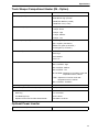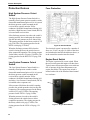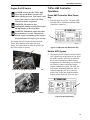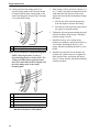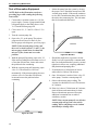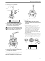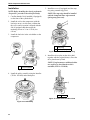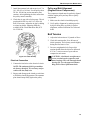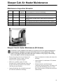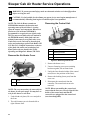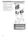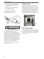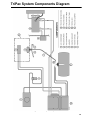
1
TriPac Auxiliary
Heating/Cooling
Temperature
Management System
TK 53036-19-MM (Rev. 1, 09/08)
Copyright© 2005 Thermo King Corp., Minneapolis, MN, USA.
Printed in USA.
The maintenance information in this manual covers unit models:
TriPac (900217)
For further information, refer to:
TriPac Operating Manual
TK 53035
TriPac Parts Manual
TK 53037
TriPac Diagnostic Manual
TK 53024
TriPac Installation Manual
TK 53120
International Components Engineering (ICE) Compressor Service Manual
ICE No. 51068
Diagnosing Thermo King Refrigeration Systems
TK 5984
Evacuation Station Operation and Field Application
TK 40612
Tool Catalog
TK 5955
Electrostatic Discharge Training Guide
TK 40282
The information in this manual is provided to assist owners, operators and service people in the proper
upkeep and maintenance of Thermo King units. The above manuals may be purchased from your local
Thermo King dealer.
This manual is published for informational purposes only and the information so provided should
not be considered as all-inclusive or covering all contingencies. If further information is required,
Thermo King Corporation should be consulted.
Sale of product shown in this manual is subject to Thermo King’s terms and conditions
including, but not limited to, the Thermo King Limited Express Warranty. Such terms and
conditions are available upon request. Thermo King’s warranty will not apply to any
equipment which has been “so repaired or altered outside the manufacturer’s plants as,
in the manufacturer’s judgment, to effect its stability.”
No warranties, express or implied, including warranties of fitness for a particular
purpose or merchantability, or warranties arising from course of dealing or usage of
trade, are made regarding the information, recommendations, and descriptions
contained herein. Manufacturer is not responsible and will not be held liable in contract
or in tort (including negligence) for any special, indirect or consequential damages,
including injury or damage caused to vehicles, contents or persons, by reason of the
installation of any Thermo King product or its mechanical failure.
Recover Refrigerant
At Thermo King, we recognize the need to preserve the environment
and limit the potential harm to the ozone layer that can result from
allowing refrigerant to escape into the atmosphere.
We strictly adhere to a policy that promotes the recovery and limits
the loss of refrigerant into the atmosphere.
In addition, service personnel must be aware of Federal and State
regulations concerning the use of refrigerants and the certification of
technicians. For additional information on regulations and technician
certification programs, contact your local THERMO KING dealer.
R-134a and PAG Compressor Oil
WARNING: Use only PAG-based refrigeration compressor oil in the
TriPac R-134a air conditioning system. See Thermo King Parts Manual
for part number.
WARNING: With HVAC systems and the use of PAG, it is very important
that oil mixing does not take place. PAG and POE oil CANNOT be mixed.
Mixing these oils will cause serious system contamination, especially with
chlorine based refrigerants.
NOTE: When servicing Thermo King R-134a units, use only those
service tools certified for and dedicated to R-134a refrigerant and PAG
compressor oils. Residual non-HFC refrigerants or oils will contaminate
R-134a systems. The proper compressor oil is determined by the
refrigerant used and specific air conditioning application requirements.
Verify both serial nameplates on the unit and compressor for correct oil to
use in a particular system. Because of the many variables in oils,
particularly in HVAC systems, compressors may be delivered with an oil
that is not specified for the particular unit it is to be fitted to. Unless it is
100% clear it is the correct oil, Thermo King recommends the oil is
changed to the correct type.
PAG oil is very hygroscopic. Only use oil taken from a fresh container.
About This Manual
Purpose
The purpose of this manual is to provide general maintenance information necessary to maintain the
TriPac unit at peak operating standards. This includes safety information, unit information such as bills of
material and kit numbers, general unit information, maintenance procedures and related information
(such as wiring and schematic diagrams), and some diagnostic and troubleshooting information.
NOTE: This manual may cover more than one unit. Therefore, it may contain information not
applicable to your unit.
Contents
This manual is organized into the following chapters:
Chapter
Purpose
Safety Precautions
Provides detailed safety information. You should be familiar with the
safety precautions before working on any unit.
Model Systems and Update
Matrices
These tables list the bills of material and kit options that make up your
unit. Use them for the following purposes:
1. To determine if you have the right manual for your unit: the bill of
material (B/M) number on your unit serial plate should match one of the
bill of material numbers listed in this publication. If you cannot find your
unit B/M, call TK Service for more information.)
2. To communicate with TK Service Department: If you need to call TK
Service, you must know your model number so that the service
representative to help you.
Specifications
Lists unit specifications.
General Description
Gives an overview description of your unit including standard and
optional features, illustrations, and general heating and air conditioning
information.
Operating Instructions
Provides unit operating instructions.
Maintenance Inspection Schedule
Table of routine maintenance procedures.
Maintenance Chapters
Provide detailed maintenance procedures required for your unit.
(Electrical, Air Conditioning, Compressor, Engine, Structural)
Wiring and Schematic Diagrams
Wiring and Schematic diagrams applicable to the unit.
5
About This Manual
Before You Call Thermo King Service!
Who to call: Your Thermo King Service Representative.
Before you call Thermo King Service, have the following information on hand:
•
Bill of Material - usually located on the unit serial plate.
•
Model Number - found on frame inside the APU unit.
Blank Pages
This manual may contain blank pages at the end of chapters. This is normal. There is no information
missing from the manual.
Roadside/Curbside Terminology
Roadside/Curbside terminology: These terms can be confusing because of differences between North
America and Europe. Please note:
Curbside:
The side of the truck to the driver’s right when the driver is in his seat and facing forward.
Roadside:
The side of the truck to the driver’s left when the driver is in his seat and facing forward.
Using the Model Tables in “About this Unit”
The model tables in this section (called “About this Unit,” “Model Systems and Update Matrices,” or
something similar) list important unit information that you will need to communicate with the Thermo
King Service Department. See the table on the previous page for a description of how to use these tables.
6
Table of Contents
About This Manual . . . . . . . . . . . . . . . . . . . . . . . . . . . . . . . . . . . . . . . . . . . . . . . . . . . . . . . . . . . . . . . . . . . . . . . 5
Purpose . . . . . . . . . . . . . . . . . . . . . . . . . . . . . . . . . . . . . . . . . . . . . . . . . . . . . . . . . . . . . . . . . . . . . . . . . . . . . . . . . 5
Contents . . . . . . . . . . . . . . . . . . . . . . . . . . . . . . . . . . . . . . . . . . . . . . . . . . . . . . . . . . . . . . . . . . . . . . . . . . . . . . . . 5
Before You Call Thermo King Service! . . . . . . . . . . . . . . . . . . . . . . . . . . . . . . . . . . . . . . . . . . . . . . . . . . . . . . . . . 6
Blank Pages . . . . . . . . . . . . . . . . . . . . . . . . . . . . . . . . . . . . . . . . . . . . . . . . . . . . . . . . . . . . . . . . . . . . . . . . . . . . . 6
Roadside/Curbside Terminology . . . . . . . . . . . . . . . . . . . . . . . . . . . . . . . . . . . . . . . . . . . . . . . . . . . . . . . . . . . . . . 6
Using the Model Tables in “About this Unit” . . . . . . . . . . . . . . . . . . . . . . . . . . . . . . . . . . . . . . . . . . . . . . . . . . . . . 6
List of Figures . . . . . . . . . . . . . . . . . . . . . . . . . . . . . . . . . . . . . . . . . . . . . . . . . . . . . . . . . . . . . . . . . . . . . . . . . . 11
Safety Precautions . . . . . . . . . . . . . . . . . . . . . . . . . . . . . . . . . . . . . . . . . . . . . . . . . . . . . . . . . . . . . . . . . . . . . . 13
General Practices . . . . . . . . . . . . . . . . . . . . . . . . . . . . . . . . . . . . . . . . . . . . . . . . . . . . . . . . . . . . . . . . . . . . . . . . 13
Refrigerant . . . . . . . . . . . . . . . . . . . . . . . . . . . . . . . . . . . . . . . . . . . . . . . . . . . . . . . . . . . . . . . . . . . . . . . . . . . . . 13
Refrigeration Oil . . . . . . . . . . . . . . . . . . . . . . . . . . . . . . . . . . . . . . . . . . . . . . . . . . . . . . . . . . . . . . . . . . . . . . . . . 13
Low Voltage . . . . . . . . . . . . . . . . . . . . . . . . . . . . . . . . . . . . . . . . . . . . . . . . . . . . . . . . . . . . . . . . . . . . . . . . . 14
Model Systems (System Designations) . . . . . . . . . . . . . . . . . . . . . . . . . . . . . . . . . . . . . . . . . . . . . . . . . . . . . 15
Specifications . . . . . . . . . . . . . . . . . . . . . . . . . . . . . . . . . . . . . . . . . . . . . . . . . . . . . . . . . . . . . . . . . . . . . . . . . . 17
TriPac Engine . . . . . . . . . . . . . . . . . . . . . . . . . . . . . . . . . . . . . . . . . . . . . . . . . . . . . . . . . . . . . . . . . . . . . . . . . . . 17
R-134a Air Conditioning System . . . . . . . . . . . . . . . . . . . . . . . . . . . . . . . . . . . . . . . . . . . . . . . . . . . . . . . . . . . . . 18
Belt Tension . . . . . . . . . . . . . . . . . . . . . . . . . . . . . . . . . . . . . . . . . . . . . . . . . . . . . . . . . . . . . . . . . . . . . . . . . . . . 18
Electrical Control System . . . . . . . . . . . . . . . . . . . . . . . . . . . . . . . . . . . . . . . . . . . . . . . . . . . . . . . . . . . . . . . . . . 18
Electrical Components . . . . . . . . . . . . . . . . . . . . . . . . . . . . . . . . . . . . . . . . . . . . . . . . . . . . . . . . . . . . . . . . . . . . 19
Truck Sleeper Compartment Heater (D2) . . . . . . . . . . . . . . . . . . . . . . . . . . . . . . . . . . . . . . . . . . . . . . . . . . . . . . 20
Truck Sleeper Compartment Heater (D4 - Option) . . . . . . . . . . . . . . . . . . . . . . . . . . . . . . . . . . . . . . . . . . . . . . . 21
Optional Power Inverter . . . . . . . . . . . . . . . . . . . . . . . . . . . . . . . . . . . . . . . . . . . . . . . . . . . . . . . . . . . . . . . . . . . 21
Optional Extreme Arctic Package Components . . . . . . . . . . . . . . . . . . . . . . . . . . . . . . . . . . . . . . . . . . . . . . . . . 22
Specifications—Compressor Oil . . . . . . . . . . . . . . . . . . . . . . . . . . . . . . . . . . . . . . . . . . . . . . . . . . . . . . . . . . . 23
General Description . . . . . . . . . . . . . . . . . . . . . . . . . . . . . . . . . . . . . . . . . . . . . . . . . . . . . . . . . . . . . . . . . . . . . 25
Introduction . . . . . . . . . . . . . . . . . . . . . . . . . . . . . . . . . . . . . . . . . . . . . . . . . . . . . . . . . . . . . . . . . . . . . . . . . . . . . 25
Unit Features . . . . . . . . . . . . . . . . . . . . . . . . . . . . . . . . . . . . . . . . . . . . . . . . . . . . . . . . . . . . . . . . . . . . . . . . . . . 25
TriPac System . . . . . . . . . . . . . . . . . . . . . . . . . . . . . . . . . . . . . . . . . . . . . . . . . . . . . . . . . . . . . . . . . . . . . . . . . . . 25
Auxiliary Power Unit . . . . . . . . . . . . . . . . . . . . . . . . . . . . . . . . . . . . . . . . . . . . . . . . . . . . . . . . . . . . . . . . . . . . . . 26
Condenser . . . . . . . . . . . . . . . . . . . . . . . . . . . . . . . . . . . . . . . . . . . . . . . . . . . . . . . . . . . . . . . . . . . . . . . . . . . . . 26
Evaporator . . . . . . . . . . . . . . . . . . . . . . . . . . . . . . . . . . . . . . . . . . . . . . . . . . . . . . . . . . . . . . . . . . . . . . . . . . . . . 26
Heater . . . . . . . . . . . . . . . . . . . . . . . . . . . . . . . . . . . . . . . . . . . . . . . . . . . . . . . . . . . . . . . . . . . . . . . . . . . . . . . . . 26
HMI Controller . . . . . . . . . . . . . . . . . . . . . . . . . . . . . . . . . . . . . . . . . . . . . . . . . . . . . . . . . . . . . . . . . . . . . . . . . . . 27
Control Circuits . . . . . . . . . . . . . . . . . . . . . . . . . . . . . . . . . . . . . . . . . . . . . . . . . . . . . . . . . . . . . . . . . . . . . . . . . . 27
Interface Board . . . . . . . . . . . . . . . . . . . . . . . . . . . . . . . . . . . . . . . . . . . . . . . . . . . . . . . . . . . . . . . . . . . . . . . . . . 27
Compressor . . . . . . . . . . . . . . . . . . . . . . . . . . . . . . . . . . . . . . . . . . . . . . . . . . . . . . . . . . . . . . . . . . . . . . . . . . . . 27
Refrigerant . . . . . . . . . . . . . . . . . . . . . . . . . . . . . . . . . . . . . . . . . . . . . . . . . . . . . . . . . . . . . . . . . . . . . . . . . . . . . 27
High System Pressure Cutout Switch . . . . . . . . . . . . . . . . . . . . . . . . . . . . . . . . . . . . . . . . . . . . . . . . . . . . . . 28
Low System Pressure Cutout Switch . . . . . . . . . . . . . . . . . . . . . . . . . . . . . . . . . . . . . . . . . . . . . . . . . . . . . . 28
Fuse Protection . . . . . . . . . . . . . . . . . . . . . . . . . . . . . . . . . . . . . . . . . . . . . . . . . . . . . . . . . . . . . . . . . . . . . . 28
Engine Reset Switch . . . . . . . . . . . . . . . . . . . . . . . . . . . . . . . . . . . . . . . . . . . . . . . . . . . . . . . . . . . . . . . . . . 28
Serial Number Locations . . . . . . . . . . . . . . . . . . . . . . . . . . . . . . . . . . . . . . . . . . . . . . . . . . . . . . . . . . . . . . . . . . . 29
Operating Instructions . . . . . . . . . . . . . . . . . . . . . . . . . . . . . . . . . . . . . . . . . . . . . . . . . . . . . . . . . . . . . . . . . . . 31
Introduction . . . . . . . . . . . . . . . . . . . . . . . . . . . . . . . . . . . . . . . . . . . . . . . . . . . . . . . . . . . . . . . . . . . . . . . . . . . . . 31
TriPac HMI Controller Description . . . . . . . . . . . . . . . . . . . . . . . . . . . . . . . . . . . . . . . . . . . . . . . . . . . . . . . . . . . . 31
HMI Controller Display . . . . . . . . . . . . . . . . . . . . . . . . . . . . . . . . . . . . . . . . . . . . . . . . . . . . . . . . . . . . . . . . . 31
Main Power Key . . . . . . . . . . . . . . . . . . . . . . . . . . . . . . . . . . . . . . . . . . . . . . . . . . . . . . . . . . . . . . . . . . . . . . 31
Mode Key . . . . . . . . . . . . . . . . . . . . . . . . . . . . . . . . . . . . . . . . . . . . . . . . . . . . . . . . . . . . . . . . . . . . . . . . . . . 31
Up and Down Keys . . . . . . . . . . . . . . . . . . . . . . . . . . . . . . . . . . . . . . . . . . . . . . . . . . . . . . . . . . . . . . . . . . . . 31
Fan Speed Key . . . . . . . . . . . . . . . . . . . . . . . . . . . . . . . . . . . . . . . . . . . . . . . . . . . . . . . . . . . . . . . . . . . . . . . 32
APU System Key . . . . . . . . . . . . . . . . . . . . . . . . . . . . . . . . . . . . . . . . . . . . . . . . . . . . . . . . . . . . . . . . . . . . . 32
System Fault Indicator . . . . . . . . . . . . . . . . . . . . . . . . . . . . . . . . . . . . . . . . . . . . . . . . . . . . . . . . . . . . . . . . . 32
7
Table of Contents
Operating Instructions (continued)
Operating Modes . . . . . . . . . . . . . . . . . . . . . . . . . . . . . . . . . . . . . . . . . . . . . . . . . . . . . . . . . . . . . . . . . . . . . . . . . 32
Air Conditioning Mode . . . . . . . . . . . . . . . . . . . . . . . . . . . . . . . . . . . . . . . . . . . . . . . . . . . . . . . . . . . . . . . . . . 32
Heat Mode . . . . . . . . . . . . . . . . . . . . . . . . . . . . . . . . . . . . . . . . . . . . . . . . . . . . . . . . . . . . . . . . . . . . . . . . . . 32
Fan Mode . . . . . . . . . . . . . . . . . . . . . . . . . . . . . . . . . . . . . . . . . . . . . . . . . . . . . . . . . . . . . . . . . . . . . . . . . . . 32
Monitor (Null) Mode . . . . . . . . . . . . . . . . . . . . . . . . . . . . . . . . . . . . . . . . . . . . . . . . . . . . . . . . . . . . . . . . . . . 32
Engine On/Off Switch . . . . . . . . . . . . . . . . . . . . . . . . . . . . . . . . . . . . . . . . . . . . . . . . . . . . . . . . . . . . . . . . . . . . . 33
TriPac HMI Controller Operation . . . . . . . . . . . . . . . . . . . . . . . . . . . . . . . . . . . . . . . . . . . . . . . . . . . . . . . . . . . . . 33
Press HMI Controller Main Power Key . . . . . . . . . . . . . . . . . . . . . . . . . . . . . . . . . . . . . . . . . . . . . . . . . . . . . 33
Enable APU System . . . . . . . . . . . . . . . . . . . . . . . . . . . . . . . . . . . . . . . . . . . . . . . . . . . . . . . . . . . . . . . . . . . 33
Engine Hourmeter Display . . . . . . . . . . . . . . . . . . . . . . . . . . . . . . . . . . . . . . . . . . . . . . . . . . . . . . . . . . . . . . 34
Select Mode of Operation . . . . . . . . . . . . . . . . . . . . . . . . . . . . . . . . . . . . . . . . . . . . . . . . . . . . . . . . . . . . . . . 34
Select Fan Speed . . . . . . . . . . . . . . . . . . . . . . . . . . . . . . . . . . . . . . . . . . . . . . . . . . . . . . . . . . . . . . . . . . . . . 34
Select Temperature Setpoint . . . . . . . . . . . . . . . . . . . . . . . . . . . . . . . . . . . . . . . . . . . . . . . . . . . . . . . . . . . . 34
System Fault Indicator . . . . . . . . . . . . . . . . . . . . . . . . . . . . . . . . . . . . . . . . . . . . . . . . . . . . . . . . . . . . . . . . . 35
Alarm Codes . . . . . . . . . . . . . . . . . . . . . . . . . . . . . . . . . . . . . . . . . . . . . . . . . . . . . . . . . . . . . . . . . . . . . . . . . 35
To Clear Alarm Codes . . . . . . . . . . . . . . . . . . . . . . . . . . . . . . . . . . . . . . . . . . . . . . . . . . . . . . . . . . . . . . . . . 35
Optional Standby Operation . . . . . . . . . . . . . . . . . . . . . . . . . . . . . . . . . . . . . . . . . . . . . . . . . . . . . . . . . . . . . 35
Options Used With Standby Operation . . . . . . . . . . . . . . . . . . . . . . . . . . . . . . . . . . . . . . . . . . . . . . . . . . . . . 36
Standby Truck Integration . . . . . . . . . . . . . . . . . . . . . . . . . . . . . . . . . . . . . . . . . . . . . . . . . . . . . . . . . . . . . . . 36
Truck Integration Selector Switch . . . . . . . . . . . . . . . . . . . . . . . . . . . . . . . . . . . . . . . . . . . . . . . . . . . . . . . . . 36
Maintenance Inspection Schedule . . . . . . . . . . . . . . . . . . . . . . . . . . . . . . . . . . . . . . . . . . . . . . . . . . . . . . . . . . 37
Engine . . . . . . . . . . . . . . . . . . . . . . . . . . . . . . . . . . . . . . . . . . . . . . . . . . . . . . . . . . . . . . . . . . . . . . . . . . . . . . . . . 37
Engine Oil Change Intervals (Change oil and filters hot) . . . . . . . . . . . . . . . . . . . . . . . . . . . . . . . . . . . . . . . . . . . 37
Electrical . . . . . . . . . . . . . . . . . . . . . . . . . . . . . . . . . . . . . . . . . . . . . . . . . . . . . . . . . . . . . . . . . . . . . . . . . . . . . . . 38
Structural . . . . . . . . . . . . . . . . . . . . . . . . . . . . . . . . . . . . . . . . . . . . . . . . . . . . . . . . . . . . . . . . . . . . . . . . . . . . . . . 38
A/C System . . . . . . . . . . . . . . . . . . . . . . . . . . . . . . . . . . . . . . . . . . . . . . . . . . . . . . . . . . . . . . . . . . . . . . . . . . . . . 38
Heater . . . . . . . . . . . . . . . . . . . . . . . . . . . . . . . . . . . . . . . . . . . . . . . . . . . . . . . . . . . . . . . . . . . . . . . . . . . . . . . . . 38
Electrical Maintenance . . . . . . . . . . . . . . . . . . . . . . . . . . . . . . . . . . . . . . . . . . . . . . . . . . . . . . . . . . . . . . . . . . . 39
Maintenance Inspection Schedule . . . . . . . . . . . . . . . . . . . . . . . . . . . . . . . . . . . . . . . . . . . . . . . . . . . . . . . . . . . . 39
Alternator Charging System Diagnostic Procedures . . . . . . . . . . . . . . . . . . . . . . . . . . . . . . . . . . . . . . . . . . . . . . 39
General Information . . . . . . . . . . . . . . . . . . . . . . . . . . . . . . . . . . . . . . . . . . . . . . . . . . . . . . . . . . . . . . . . . . . 39
Alternator Identification . . . . . . . . . . . . . . . . . . . . . . . . . . . . . . . . . . . . . . . . . . . . . . . . . . . . . . . . . . . . . . . . . 39
Test Equipment for Checking Voltage and Current . . . . . . . . . . . . . . . . . . . . . . . . . . . . . . . . . . . . . . . . . . . 41
Alternator Load Test . . . . . . . . . . . . . . . . . . . . . . . . . . . . . . . . . . . . . . . . . . . . . . . . . . . . . . . . . . . . . . . . . . . 41
General Diagnostic and Warranty Evaluation Procedure . . . . . . . . . . . . . . . . . . . . . . . . . . . . . . . . . . . . . . . 41
Field Current Test . . . . . . . . . . . . . . . . . . . . . . . . . . . . . . . . . . . . . . . . . . . . . . . . . . . . . . . . . . . . . . . . . . . . . 43
Glow Plugs . . . . . . . . . . . . . . . . . . . . . . . . . . . . . . . . . . . . . . . . . . . . . . . . . . . . . . . . . . . . . . . . . . . . . . . . . . . . . 43
High Coolant Temperature Sensor . . . . . . . . . . . . . . . . . . . . . . . . . . . . . . . . . . . . . . . . . . . . . . . . . . . . . . . . . . . 43
Low Oil Pressure Switch . . . . . . . . . . . . . . . . . . . . . . . . . . . . . . . . . . . . . . . . . . . . . . . . . . . . . . . . . . . . . . . . . . . 43
Condenser and Pre-cooler Axial Fan Motors . . . . . . . . . . . . . . . . . . . . . . . . . . . . . . . . . . . . . . . . . . . . . . . . . . . 44
Axial Fan Motor Removal and Installation . . . . . . . . . . . . . . . . . . . . . . . . . . . . . . . . . . . . . . . . . . . . . . . . . . 44
Evaporator Blower Motor . . . . . . . . . . . . . . . . . . . . . . . . . . . . . . . . . . . . . . . . . . . . . . . . . . . . . . . . . . . . . . . . . . . 45
Evaporator Blower Motor Removal and Installation . . . . . . . . . . . . . . . . . . . . . . . . . . . . . . . . . . . . . . . . . . . 45
Engine Maintenance . . . . . . . . . . . . . . . . . . . . . . . . . . . . . . . . . . . . . . . . . . . . . . . . . . . . . . . . . . . . . . . . . . . . . 47
Maintenance Inspection Schedule . . . . . . . . . . . . . . . . . . . . . . . . . . . . . . . . . . . . . . . . . . . . . . . . . . . . . . . . . . . . 47
Engine Oil Change Intervals (Change oil and filters hot) . . . . . . . . . . . . . . . . . . . . . . . . . . . . . . . . . . . . . . . . . . . 47
Engine Lubrication System . . . . . . . . . . . . . . . . . . . . . . . . . . . . . . . . . . . . . . . . . . . . . . . . . . . . . . . . . . . . . . 47
Engine Reset Switch . . . . . . . . . . . . . . . . . . . . . . . . . . . . . . . . . . . . . . . . . . . . . . . . . . . . . . . . . . . . . . . . . . . 48
Engine Oil Change . . . . . . . . . . . . . . . . . . . . . . . . . . . . . . . . . . . . . . . . . . . . . . . . . . . . . . . . . . . . . . . . . . . . 48
Oil Filter Change . . . . . . . . . . . . . . . . . . . . . . . . . . . . . . . . . . . . . . . . . . . . . . . . . . . . . . . . . . . . . . . . . . . . . . . . . 48
Crankcase Breather . . . . . . . . . . . . . . . . . . . . . . . . . . . . . . . . . . . . . . . . . . . . . . . . . . . . . . . . . . . . . . . . . . . . . . . 48
Engine Air Cleaner . . . . . . . . . . . . . . . . . . . . . . . . . . . . . . . . . . . . . . . . . . . . . . . . . . . . . . . . . . . . . . . . . . . . . . . 49
Engine Cooling System . . . . . . . . . . . . . . . . . . . . . . . . . . . . . . . . . . . . . . . . . . . . . . . . . . . . . . . . . . . . . . . . . . . . 49
Antifreeze Maintenance Procedures . . . . . . . . . . . . . . . . . . . . . . . . . . . . . . . . . . . . . . . . . . . . . . . . . . . . . . . 52
TriPac Engine Coolant Maintenance Checks: . . . . . . . . . . . . . . . . . . . . . . . . . . . . . . . . . . . . . . . . . . . . . . . 52
Bleeding the Coolant System . . . . . . . . . . . . . . . . . . . . . . . . . . . . . . . . . . . . . . . . . . . . . . . . . . . . . . . . . . . . 53
8
Table of Contents
Engine Maintenance (continued)
Engine Fuel System . . . . . . . . . . . . . . . . . . . . . . . . . . . . . . . . . . . . . . . . . . . . . . . . . . . . . . . . . . . . . . . . . . . . . . 54
Bleeding the Fuel System . . . . . . . . . . . . . . . . . . . . . . . . . . . . . . . . . . . . . . . . . . . . . . . . . . . . . . . . . . . . . . . 55
Water in the Fuel System . . . . . . . . . . . . . . . . . . . . . . . . . . . . . . . . . . . . . . . . . . . . . . . . . . . . . . . . . . . . . . . 56
Fuel Filter Replacement . . . . . . . . . . . . . . . . . . . . . . . . . . . . . . . . . . . . . . . . . . . . . . . . . . . . . . . . . . . . . . . . 56
Injection Pump Timing . . . . . . . . . . . . . . . . . . . . . . . . . . . . . . . . . . . . . . . . . . . . . . . . . . . . . . . . . . . . . . . . . 56
Injection Pump Removal and Installation . . . . . . . . . . . . . . . . . . . . . . . . . . . . . . . . . . . . . . . . . . . . . . . . . . . 59
Integral Fuel Solenoid . . . . . . . . . . . . . . . . . . . . . . . . . . . . . . . . . . . . . . . . . . . . . . . . . . . . . . . . . . . . . . . . . . . . . 61
Fuel Solenoid Replacement . . . . . . . . . . . . . . . . . . . . . . . . . . . . . . . . . . . . . . . . . . . . . . . . . . . . . . . . . . . . . 63
Valve Clearance Adjustment . . . . . . . . . . . . . . . . . . . . . . . . . . . . . . . . . . . . . . . . . . . . . . . . . . . . . . . . . . . . . . . . 64
Engine Speed Adjustment . . . . . . . . . . . . . . . . . . . . . . . . . . . . . . . . . . . . . . . . . . . . . . . . . . . . . . . . . . . . . . . . . 65
Belt Adjustment . . . . . . . . . . . . . . . . . . . . . . . . . . . . . . . . . . . . . . . . . . . . . . . . . . . . . . . . . . . . . . . . . . . . . . . . . . 66
Engine/Compressor/Alternator Belt Tension/Adjustment . . . . . . . . . . . . . . . . . . . . . . . . . . . . . . . . . . . . . . . 66
Air Conditioning Maintenance . . . . . . . . . . . . . . . . . . . . . . . . . . . . . . . . . . . . . . . . . . . . . . . . . . . . . . . . . . . . . 67
Maintenance Inspection Schedule . . . . . . . . . . . . . . . . . . . . . . . . . . . . . . . . . . . . . . . . . . . . . . . . . . . . . . . . . . . 67
Safety . . . . . . . . . . . . . . . . . . . . . . . . . . . . . . . . . . . . . . . . . . . . . . . . . . . . . . . . . . . . . . . . . . . . . . . . . . . . . . . . . 67
Refrigerant Service Safety Procedures . . . . . . . . . . . . . . . . . . . . . . . . . . . . . . . . . . . . . . . . . . . . . . . . . . . . 67
General Refrigerant Handling Procedures . . . . . . . . . . . . . . . . . . . . . . . . . . . . . . . . . . . . . . . . . . . . . . . . . . 67
PAG Oil Handling Procedures . . . . . . . . . . . . . . . . . . . . . . . . . . . . . . . . . . . . . . . . . . . . . . . . . . . . . . . . . . . 68
Gauge Manifold Connections . . . . . . . . . . . . . . . . . . . . . . . . . . . . . . . . . . . . . . . . . . . . . . . . . . . . . . . . . . . . 68
Gauge Manifold Positions . . . . . . . . . . . . . . . . . . . . . . . . . . . . . . . . . . . . . . . . . . . . . . . . . . . . . . . . . . . . . . . 68
Gauge Connections . . . . . . . . . . . . . . . . . . . . . . . . . . . . . . . . . . . . . . . . . . . . . . . . . . . . . . . . . . . . . . . . . . . 68
Gauge Manifold Attachment and Purging . . . . . . . . . . . . . . . . . . . . . . . . . . . . . . . . . . . . . . . . . . . . . . . . . . . 70
Removal . . . . . . . . . . . . . . . . . . . . . . . . . . . . . . . . . . . . . . . . . . . . . . . . . . . . . . . . . . . . . . . . . . . . . . . . . . . . 70
Refrigerant Recovery . . . . . . . . . . . . . . . . . . . . . . . . . . . . . . . . . . . . . . . . . . . . . . . . . . . . . . . . . . . . . . . . . . . . . 70
Evacuation . . . . . . . . . . . . . . . . . . . . . . . . . . . . . . . . . . . . . . . . . . . . . . . . . . . . . . . . . . . . . . . . . . . . . . . . . . . . . 71
Test of Evacuation Equipment . . . . . . . . . . . . . . . . . . . . . . . . . . . . . . . . . . . . . . . . . . . . . . . . . . . . . . . . . . . 74
Unit Evacuation Procedure . . . . . . . . . . . . . . . . . . . . . . . . . . . . . . . . . . . . . . . . . . . . . . . . . . . . . . . . . . . . . . 75
Charging Procedures . . . . . . . . . . . . . . . . . . . . . . . . . . . . . . . . . . . . . . . . . . . . . . . . . . . . . . . . . . . . . . . . . . . . . 76
Charging from an Evacuated State . . . . . . . . . . . . . . . . . . . . . . . . . . . . . . . . . . . . . . . . . . . . . . . . . . . . . . . 76
Charging from a Partially Charged State . . . . . . . . . . . . . . . . . . . . . . . . . . . . . . . . . . . . . . . . . . . . . . . . . . . 76
Charging Your Air Conditioning System In Cooler Weather . . . . . . . . . . . . . . . . . . . . . . . . . . . . . . . . . . . . . 77
Testing System for Leaks . . . . . . . . . . . . . . . . . . . . . . . . . . . . . . . . . . . . . . . . . . . . . . . . . . . . . . . . . . . . . . . . . . 77
0 PSI Reading . . . . . . . . . . . . . . . . . . . . . . . . . . . . . . . . . . . . . . . . . . . . . . . . . . . . . . . . . . . . . . . . . . . . . . . 78
1 to 50 PSI Reading . . . . . . . . . . . . . . . . . . . . . . . . . . . . . . . . . . . . . . . . . . . . . . . . . . . . . . . . . . . . . . . . . . . 78
Over 50 PSI Reading . . . . . . . . . . . . . . . . . . . . . . . . . . . . . . . . . . . . . . . . . . . . . . . . . . . . . . . . . . . . . . . . . . 78
Receiver-Drier Removal and Installation . . . . . . . . . . . . . . . . . . . . . . . . . . . . . . . . . . . . . . . . . . . . . . . . . . . . . . . 78
TM-15 Compressor Maintenance . . . . . . . . . . . . . . . . . . . . . . . . . . . . . . . . . . . . . . . . . . . . . . . . . . . . . . . . . . . 81
Compressor Handling and Storage . . . . . . . . . . . . . . . . . . . . . . . . . . . . . . . . . . . . . . . . . . . . . . . . . . . . . . . . . . . 82
Removing the Compressor . . . . . . . . . . . . . . . . . . . . . . . . . . . . . . . . . . . . . . . . . . . . . . . . . . . . . . . . . . . . . . . . . 82
Compressor Installation Procedures . . . . . . . . . . . . . . . . . . . . . . . . . . . . . . . . . . . . . . . . . . . . . . . . . . . . . . . . . . 82
Installation Precautions . . . . . . . . . . . . . . . . . . . . . . . . . . . . . . . . . . . . . . . . . . . . . . . . . . . . . . . . . . . . . . . . 82
Installing the Compressor . . . . . . . . . . . . . . . . . . . . . . . . . . . . . . . . . . . . . . . . . . . . . . . . . . . . . . . . . . . . . . . 83
Compressor Oil Caution Statements . . . . . . . . . . . . . . . . . . . . . . . . . . . . . . . . . . . . . . . . . . . . . . . . . . . . . . 83
Oil Charge Considerations . . . . . . . . . . . . . . . . . . . . . . . . . . . . . . . . . . . . . . . . . . . . . . . . . . . . . . . . . . . . . . 83
Oil Type Considerations . . . . . . . . . . . . . . . . . . . . . . . . . . . . . . . . . . . . . . . . . . . . . . . . . . . . . . . . . . . . . . . . 84
Oil Check Interval . . . . . . . . . . . . . . . . . . . . . . . . . . . . . . . . . . . . . . . . . . . . . . . . . . . . . . . . . . . . . . . . . . . . . 84
Oil Check Procedure: Draining, Measuring, and Inspecting the Oil . . . . . . . . . . . . . . . . . . . . . . . . . . . . . . . . . . 84
Clutch Procedures . . . . . . . . . . . . . . . . . . . . . . . . . . . . . . . . . . . . . . . . . . . . . . . . . . . . . . . . . . . . . . . . . . . . . . . 86
Clutch Test . . . . . . . . . . . . . . . . . . . . . . . . . . . . . . . . . . . . . . . . . . . . . . . . . . . . . . . . . . . . . . . . . . . . . . . . . . 86
Clutch Removal, Inspection, and Installation . . . . . . . . . . . . . . . . . . . . . . . . . . . . . . . . . . . . . . . . . . . . . . . . 86
Removal . . . . . . . . . . . . . . . . . . . . . . . . . . . . . . . . . . . . . . . . . . . . . . . . . . . . . . . . . . . . . . . . . . . . . . . . . . . . 86
Inspection . . . . . . . . . . . . . . . . . . . . . . . . . . . . . . . . . . . . . . . . . . . . . . . . . . . . . . . . . . . . . . . . . . . . . . . . . . . 87
Installation . . . . . . . . . . . . . . . . . . . . . . . . . . . . . . . . . . . . . . . . . . . . . . . . . . . . . . . . . . . . . . . . . . . . . . . . . . 88
Pulley and Belt Alignment (Engine-Driven Compressor) . . . . . . . . . . . . . . . . . . . . . . . . . . . . . . . . . . . . . . . 89
Belt Tension . . . . . . . . . . . . . . . . . . . . . . . . . . . . . . . . . . . . . . . . . . . . . . . . . . . . . . . . . . . . . . . . . . . . . . . . . . . . 89
9
Table of Contents
Sleeper Cab Air Heater Maintenance . . . . . . . . . . . . . . . . . . . . . . . . . . . . . . . . . . . . . . . . . . . . . . . . . . . . . . . . 91
Maintenance Inspection Schedule . . . . . . . . . . . . . . . . . . . . . . . . . . . . . . . . . . . . . . . . . . . . . . . . . . . . . . . . . . . . 91
Sleeper Cab Air Heater Maintenance (D2 shown) . . . . . . . . . . . . . . . . . . . . . . . . . . . . . . . . . . . . . . . . . . . . . . . 91
Sleeper Cab Air Heater Service Operations . . . . . . . . . . . . . . . . . . . . . . . . . . . . . . . . . . . . . . . . . . . . . . . . . . 92
Remove the Air Heater Cover . . . . . . . . . . . . . . . . . . . . . . . . . . . . . . . . . . . . . . . . . . . . . . . . . . . . . . . . . . . . 92
Removing the Control Unit . . . . . . . . . . . . . . . . . . . . . . . . . . . . . . . . . . . . . . . . . . . . . . . . . . . . . . . . . . . . . . 92
Heater Casing Disassembly and Glow Pin Removal . . . . . . . . . . . . . . . . . . . . . . . . . . . . . . . . . . . . . . . . . . 93
Removing the Glow Plug Support Lining . . . . . . . . . . . . . . . . . . . . . . . . . . . . . . . . . . . . . . . . . . . . . . . . . . . 93
Removing the Overheating Sensor / Flame Sensor . . . . . . . . . . . . . . . . . . . . . . . . . . . . . . . . . . . . . . . . . . . 94
Checking the Overheating / Flame Sensor . . . . . . . . . . . . . . . . . . . . . . . . . . . . . . . . . . . . . . . . . . . . . . . . . . 94
Overheating Sensor . . . . . . . . . . . . . . . . . . . . . . . . . . . . . . . . . . . . . . . . . . . . . . . . . . . . . . . . . . . . . . . . . . . 94
Flame Sensor . . . . . . . . . . . . . . . . . . . . . . . . . . . . . . . . . . . . . . . . . . . . . . . . . . . . . . . . . . . . . . . . . . . . . . . . 94
Installing the Overheating / Flame Sensor . . . . . . . . . . . . . . . . . . . . . . . . . . . . . . . . . . . . . . . . . . . . . . . . . . 95
Dismantling the Heat Exchanger and Removing the Combustion Air Blower . . . . . . . . . . . . . . . . . . . . . . . . 96
Removing the Combustion Chamber . . . . . . . . . . . . . . . . . . . . . . . . . . . . . . . . . . . . . . . . . . . . . . . . . . . . . . 97
Optional Power Inverter . . . . . . . . . . . . . . . . . . . . . . . . . . . . . . . . . . . . . . . . . . . . . . . . . . . . . . . . . . . . . . . . . . 99
Optional Power Inverter . . . . . . . . . . . . . . . . . . . . . . . . . . . . . . . . . . . . . . . . . . . . . . . . . . . . . . . . . . . . . . . . . . . . 99
Structural Maintenance . . . . . . . . . . . . . . . . . . . . . . . . . . . . . . . . . . . . . . . . . . . . . . . . . . . . . . . . . . . . . . . . . . 101
Maintenance Inspection Schedule . . . . . . . . . . . . . . . . . . . . . . . . . . . . . . . . . . . . . . . . . . . . . . . . . . . . . . . . . . . 101
Evaporator Coil . . . . . . . . . . . . . . . . . . . . . . . . . . . . . . . . . . . . . . . . . . . . . . . . . . . . . . . . . . . . . . . . . . . . . . . . . 101
Evaporator Coil Air Filter . . . . . . . . . . . . . . . . . . . . . . . . . . . . . . . . . . . . . . . . . . . . . . . . . . . . . . . . . . . . . . . 101
Evaporator Drain Valves . . . . . . . . . . . . . . . . . . . . . . . . . . . . . . . . . . . . . . . . . . . . . . . . . . . . . . . . . . . . . . . 102
Condenser Coil . . . . . . . . . . . . . . . . . . . . . . . . . . . . . . . . . . . . . . . . . . . . . . . . . . . . . . . . . . . . . . . . . . . . . . . . . 102
APU Mounting Bolts . . . . . . . . . . . . . . . . . . . . . . . . . . . . . . . . . . . . . . . . . . . . . . . . . . . . . . . . . . . . . . . . . . . . . 102
TriPac System Components Diagram . . . . . . . . . . . . . . . . . . . . . . . . . . . . . . . . . . . . . . . . . . . . . . . . . . . . . . 103
Index . . . . . . . . . . . . . . . . . . . . . . . . . . . . . . . . . . . . . . . . . . . . . . . . . . . . . . . . . . . . . . . . . . . . . . . . . . . . . . . . . 105
Wiring and Schematic Diagrams Index . . . . . . . . . . . . . . . . . . . . . . . . . . . . . . . . . . . . . . . . . . . . . . . . . . . . . 107
10
List of Figures
Figure 1: TriPac APU . . . . . . . . . . . . . . . . . . . . . . . . . . . . . . . . . . . . . . . . . . . . . . . . . . . . . . . . . . . . . . . . . . . . . 26
Figure 2: TriPac Condenser . . . . . . . . . . . . . . . . . . . . . . . . . . . . . . . . . . . . . . . . . . . . . . . . . . . . . . . . . . . . . . . . 26
Figure 3: TriPac Evaporator and Air Ducts (Evaporator installed under sleeper cab bunk) . . . . . . . . . . . . . . . . 26
Figure 4: TriPac Heater . . . . . . . . . . . . . . . . . . . . . . . . . . . . . . . . . . . . . . . . . . . . . . . . . . . . . . . . . . . . . . . . . . . . 26
Figure 5: TriPac HMI Controller . . . . . . . . . . . . . . . . . . . . . . . . . . . . . . . . . . . . . . . . . . . . . . . . . . . . . . . . . . . . . 27
Figure 6: Interface Board . . . . . . . . . . . . . . . . . . . . . . . . . . . . . . . . . . . . . . . . . . . . . . . . . . . . . . . . . . . . . . . . . . 28
Figure 7: Engine Reset Switch . . . . . . . . . . . . . . . . . . . . . . . . . . . . . . . . . . . . . . . . . . . . . . . . . . . . . . . . . . . . . . 28
Figure 8: HMI Controller . . . . . . . . . . . . . . . . . . . . . . . . . . . . . . . . . . . . . . . . . . . . . . . . . . . . . . . . . . . . . . . . . . 31
Figure 9: Early Engine On/Off Switch Location . . . . . . . . . . . . . . . . . . . . . . . . . . . . . . . . . . . . . . . . . . . . . . . . . . 33
Figure 10: Later Engine On/Off Switch Location . . . . . . . . . . . . . . . . . . . . . . . . . . . . . . . . . . . . . . . . . . . . . . . . . 33
Figure 11: HMI Controller Main Power Key . . . . . . . . . . . . . . . . . . . . . . . . . . . . . . . . . . . . . . . . . . . . . . . . . . . . . 33
Figure 12: APU System Key . . . . . . . . . . . . . . . . . . . . . . . . . . . . . . . . . . . . . . . . . . . . . . . . . . . . . . . . . . . . . . . . 33
Figure 13: Engine Hour Meter Display . . . . . . . . . . . . . . . . . . . . . . . . . . . . . . . . . . . . . . . . . . . . . . . . . . . . . . . . 34
Figure 14: Mode Key . . . . . . . . . . . . . . . . . . . . . . . . . . . . . . . . . . . . . . . . . . . . . . . . . . . . . . . . . . . . . . . . . . . . . . 34
Figure 15: Fan Speed Key . . . . . . . . . . . . . . . . . . . . . . . . . . . . . . . . . . . . . . . . . . . . . . . . . . . . . . . . . . . . . . . . . 34
Figure 16: Up and Down Keys . . . . . . . . . . . . . . . . . . . . . . . . . . . . . . . . . . . . . . . . . . . . . . . . . . . . . . . . . . . . . . 34
Figure 17: System Fault Indicator . . . . . . . . . . . . . . . . . . . . . . . . . . . . . . . . . . . . . . . . . . . . . . . . . . . . . . . . . . . . 35
Figure 18: Standby Operation . . . . . . . . . . . . . . . . . . . . . . . . . . . . . . . . . . . . . . . . . . . . . . . . . . . . . . . . . . . . . . . 35
Figure 19: Australian Bosch Alternator Terminal and Component Locations . . . . . . . . . . . . . . . . . . . . . . . . . . 40
Figure 20: Thermo King Alternator Terminal and Component Locations . . . . . . . . . . . . . . . . . . . . . . . . . . . . . 40
Figure 21: Axial Fan Motor . . . . . . . . . . . . . . . . . . . . . . . . . . . . . . . . . . . . . . . . . . . . . . . . . . . . . . . . . . . . . . . . . 44
Figure 22: Evaporator Assembly (Cover Removed) . . . . . . . . . . . . . . . . . . . . . . . . . . . . . . . . . . . . . . . . . . . . . . 45
Figure 23: Engine Reset Switch . . . . . . . . . . . . . . . . . . . . . . . . . . . . . . . . . . . . . . . . . . . . . . . . . . . . . . . . . . . . . 48
Figure 24: Oil Filter Parts . . . . . . . . . . . . . . . . . . . . . . . . . . . . . . . . . . . . . . . . . . . . . . . . . . . . . . . . . . . . . . . . . . 48
Figure 25: Air Cleaner . . . . . . . . . . . . . . . . . . . . . . . . . . . . . . . . . . . . . . . . . . . . . . . . . . . . . . . . . . . . . . . . . . . . . 49
Figure 26: Engine Cooling System Components, Before 10/06 . . . . . . . . . . . . . . . . . . . . . . . . . . . . . . . . . . . . 50
Figure 27: Engine Cooling System Components, 10/06 and After . . . . . . . . . . . . . . . . . . . . . . . . . . . . . . . . . . 51
Figure 28: Water Pump Assembly and Thermostat . . . . . . . . . . . . . . . . . . . . . . . . . . . . . . . . . . . . . . . . . . . . . . 52
Figure 29: Water Pump Bleeder Bolt and Bleed Petcock Locations . . . . . . . . . . . . . . . . . . . . . . . . . . . . . . . . . . 53
Figure 30: Engine Fuel System, Rubber Fuel Lines . . . . . . . . . . . . . . . . . . . . . . . . . . . . . . . . . . . . . . . . . . . . . . 54
Figure 31: Engine Fuel System, Nylon Fuel Lines . . . . . . . . . . . . . . . . . . . . . . . . . . . . . . . . . . . . . . . . . . . . . . . 55
Figure 32: Fuel Return Line Banjo Fitting . . . . . . . . . . . . . . . . . . . . . . . . . . . . . . . . . . . . . . . . . . . . . . . . . . . . . . 55
Figure 33: Component Location . . . . . . . . . . . . . . . . . . . . . . . . . . . . . . . . . . . . . . . . . . . . . . . . . . . . . . . . . . . . . 56
Figure 34: Timing Marks . . . . . . . . . . . . . . . . . . . . . . . . . . . . . . . . . . . . . . . . . . . . . . . . . . . . . . . . . . . . . . . . . . . 57
Figure 35: Injection Pump . . . . . . . . . . . . . . . . . . . . . . . . . . . . . . . . . . . . . . . . . . . . . . . . . . . . . . . . . . . . . . . . . . 57
Figure 36: Correct Injection Timing Mark Alignment . . . . . . . . . . . . . . . . . . . . . . . . . . . . . . . . . . . . . . . . . . . . . . 58
Figure 37: Correct Injection Timing Mark Alignment With Series Of Injection Timing Marks . . . . . . . . . . . . . . . 58
Figure 38: Index Mark Location . . . . . . . . . . . . . . . . . . . . . . . . . . . . . . . . . . . . . . . . . . . . . . . . . . . . . . . . . . . . . 59
Figure 39: Index Mark Alignment . . . . . . . . . . . . . . . . . . . . . . . . . . . . . . . . . . . . . . . . . . . . . . . . . . . . . . . . . . . . 59
Figure 40: Injection Pump Removal and Installation . . . . . . . . . . . . . . . . . . . . . . . . . . . . . . . . . . . . . . . . . . . . . 60
Figure 41: Integral Fuel Solenoid Components . . . . . . . . . . . . . . . . . . . . . . . . . . . . . . . . . . . . . . . . . . . . . . . . . 61
Figure 42: Fuel Solenoid Pin Identification . . . . . . . . . . . . . . . . . . . . . . . . . . . . . . . . . . . . . . . . . . . . . . . . . . . . . 61
Figure 43: Fuel Solenoid Components . . . . . . . . . . . . . . . . . . . . . . . . . . . . . . . . . . . . . . . . . . . . . . . . . . . . . . . . 63
Figure 44: Timing Marks . . . . . . . . . . . . . . . . . . . . . . . . . . . . . . . . . . . . . . . . . . . . . . . . . . . . . . . . . . . . . . . . . . . 64
Figure 45: Valve Clearance . . . . . . . . . . . . . . . . . . . . . . . . . . . . . . . . . . . . . . . . . . . . . . . . . . . . . . . . . . . . . . . . 64
Figure 46: Adjusting Valves . . . . . . . . . . . . . . . . . . . . . . . . . . . . . . . . . . . . . . . . . . . . . . . . . . . . . . . . . . . . . . . . 65
Figure 47: Engine Speed Adjustment . . . . . . . . . . . . . . . . . . . . . . . . . . . . . . . . . . . . . . . . . . . . . . . . . . . . . . . . . 65
Figure 48: Belt and Pulley Group . . . . . . . . . . . . . . . . . . . . . . . . . . . . . . . . . . . . . . . . . . . . . . . . . . . . . . . . . . . 66
Figure 49: Hand Valves Opened to Center Port . . . . . . . . . . . . . . . . . . . . . . . . . . . . . . . . . . . . . . . . . . . . . . . . . 68
Figure 50: Hand Valves Closed to Center Port . . . . . . . . . . . . . . . . . . . . . . . . . . . . . . . . . . . . . . . . . . . . . . . . . . 68
Figure 51: Connecting the Gauge Manifold . . . . . . . . . . . . . . . . . . . . . . . . . . . . . . . . . . . . . . . . . . . . . . . . . . . . 68
Figure 52: Balancing the Pressure . . . . . . . . . . . . . . . . . . . . . . . . . . . . . . . . . . . . . . . . . . . . . . . . . . . . . . . . . . . 69
Figure 53: Evacuating the System . . . . . . . . . . . . . . . . . . . . . . . . . . . . . . . . . . . . . . . . . . . . . . . . . . . . . . . . . . . 69
Figure 54: Recovering Refrigerant . . . . . . . . . . . . . . . . . . . . . . . . . . . . . . . . . . . . . . . . . . . . . . . . . . . . . . . . . . . 69
Figure 55: Liquid Charging the System . . . . . . . . . . . . . . . . . . . . . . . . . . . . . . . . . . . . . . . . . . . . . . . . . . . . . . . . 69
Figure 56: Evacuation Station . . . . . . . . . . . . . . . . . . . . . . . . . . . . . . . . . . . . . . . . . . . . . . . . . . . . . . . . . . . . . . 72
Figure 57: Vacuum Gauge . . . . . . . . . . . . . . . . . . . . . . . . . . . . . . . . . . . . . . . . . . . . . . . . . . . . . . . . . . . . . . . . 73
Figure 58: Leak . . . . . . . . . . . . . . . . . . . . . . . . . . . . . . . . . . . . . . . . . . . . . . . . . . . . . . . . . . . . . . . . . . . . . . . . . . 74
11
List of Figures
Figure 59: Moisture . . . . . . . . . . . . . . . . . . . . . . . . . . . . . . . . . . . . . . . . . . . . . . . . . . . . . . . . . . . . . . . . . . . . . . . 74
Figure 60: Connect Gauge Manifold . . . . . . . . . . . . . . . . . . . . . . . . . . . . . . . . . . . . . . . . . . . . . . . . . . . . . . . . . . 75
Figure 61: Receiver-Drier . . . . . . . . . . . . . . . . . . . . . . . . . . . . . . . . . . . . . . . . . . . . . . . . . . . . . . . . . . . . . . . . . . 78
Figure 62: Compressor Components . . . . . . . . . . . . . . . . . . . . . . . . . . . . . . . . . . . . . . . . . . . . . . . . . . . . . . . . 81
Figure 63: Read the Label . . . . . . . . . . . . . . . . . . . . . . . . . . . . . . . . . . . . . . . . . . . . . . . . . . . . . . . . . . . . . . . . . . 82
Figure 64: Loosen Caps Slowly . . . . . . . . . . . . . . . . . . . . . . . . . . . . . . . . . . . . . . . . . . . . . . . . . . . . . . . . . . . . . . 82
Figure 65: Rotate Armature Plate . . . . . . . . . . . . . . . . . . . . . . . . . . . . . . . . . . . . . . . . . . . . . . . . . . . . . . . . . . . . 83
Figure 66: Draining the Oil . . . . . . . . . . . . . . . . . . . . . . . . . . . . . . . . . . . . . . . . . . . . . . . . . . . . . . . . . . . . . . . . . . 84
Figure 67: Armature Plate Rotation . . . . . . . . . . . . . . . . . . . . . . . . . . . . . . . . . . . . . . . . . . . . . . . . . . . . . . . . . . . 84
Figure 68: Small Compressor Oil Fill Procedure . . . . . . . . . . . . . . . . . . . . . . . . . . . . . . . . . . . . . . . . . . . . . . . . . 86
Figure 69: Remove Center Bolt . . . . . . . . . . . . . . . . . . . . . . . . . . . . . . . . . . . . . . . . . . . . . . . . . . . . . . . . . . . . . . 86
Figure 70: Remove Armature Plate . . . . . . . . . . . . . . . . . . . . . . . . . . . . . . . . . . . . . . . . . . . . . . . . . . . . . . . . . . . 86
Figure 71: Remove Snap Ring and Cover . . . . . . . . . . . . . . . . . . . . . . . . . . . . . . . . . . . . . . . . . . . . . . . . . . . . . . 87
Figure 72: Remove Pulley . . . . . . . . . . . . . . . . . . . . . . . . . . . . . . . . . . . . . . . . . . . . . . . . . . . . . . . . . . . . . . . . . . 87
Figure 73: Remove Coil . . . . . . . . . . . . . . . . . . . . . . . . . . . . . . . . . . . . . . . . . . . . . . . . . . . . . . . . . . . . . . . . . . . . 87
Figure 74: Inspect Clutch Components . . . . . . . . . . . . . . . . . . . . . . . . . . . . . . . . . . . . . . . . . . . . . . . . . . . . . . . . 87
Figure 75: Install Coil . . . . . . . . . . . . . . . . . . . . . . . . . . . . . . . . . . . . . . . . . . . . . . . . . . . . . . . . . . . . . . . . . . . . . . 88
Figure 76: Install Pulley . . . . . . . . . . . . . . . . . . . . . . . . . . . . . . . . . . . . . . . . . . . . . . . . . . . . . . . . . . . . . . . . . . . . 88
Figure 77: Install Cover and Snap Ring . . . . . . . . . . . . . . . . . . . . . . . . . . . . . . . . . . . . . . . . . . . . . . . . . . . . . . . . 88
Figure 78: Install Shims and Drive Plate . . . . . . . . . . . . . . . . . . . . . . . . . . . . . . . . . . . . . . . . . . . . . . . . . . . . . . . 88
Figure 79: Check Air Gap . . . . . . . . . . . . . . . . . . . . . . . . . . . . . . . . . . . . . . . . . . . . . . . . . . . . . . . . . . . . . . . . . . 89
Figure 80: Remove Air Heater Cover . . . . . . . . . . . . . . . . . . . . . . . . . . . . . . . . . . . . . . . . . . . . . . . . . . . . . . . . . 92
Figure 81: Removing Control Unit . . . . . . . . . . . . . . . . . . . . . . . . . . . . . . . . . . . . . . . . . . . . . . . . . . . . . . . . . . . . 92
Figure 82: Heater Casing Disassembly and Glow Pin Removal . . . . . . . . . . . . . . . . . . . . . . . . . . . . . . . . . . . . . 93
Figure 83: Removing the Glow Plug Support Lining . . . . . . . . . . . . . . . . . . . . . . . . . . . . . . . . . . . . . . . . . . . . . . 93
Figure 84: Removing the overheating sensor / flame sensor . . . . . . . . . . . . . . . . . . . . . . . . . . . . . . . . . . . . . . . 94
Figure 85: Overheating Sensor and Flame Sensor . . . . . . . . . . . . . . . . . . . . . . . . . . . . . . . . . . . . . . . . . . . . . . . 94
Figure 86: Installing the overheating / flame sensor . . . . . . . . . . . . . . . . . . . . . . . . . . . . . . . . . . . . . . . . . . . . . . 95
Figure 87: Dismantling the Heat Exchanger and Removing the Combustion Air Blower . . . . . . . . . . . . . . . . . . 96
Figure 88: Removing the Combustion Chamber . . . . . . . . . . . . . . . . . . . . . . . . . . . . . . . . . . . . . . . . . . . . . . . . . 97
Figure 89: Evaporator (Cover Removed) . . . . . . . . . . . . . . . . . . . . . . . . . . . . . . . . . . . . . . . . . . . . . . . . . . . . . 101
Figure 90: Evaporator Coil Air Filter . . . . . . . . . . . . . . . . . . . . . . . . . . . . . . . . . . . . . . . . . . . . . . . . . . . . . . . . . 101
Figure 91: Drain Valves . . . . . . . . . . . . . . . . . . . . . . . . . . . . . . . . . . . . . . . . . . . . . . . . . . . . . . . . . . . . . . . . . . . 102
Figure 92: Condenser . . . . . . . . . . . . . . . . . . . . . . . . . . . . . . . . . . . . . . . . . . . . . . . . . . . . . . . . . . . . . . . . . . . . 102
Figure 93: TriPac System Components . . . . . . . . . . . . . . . . . . . . . . . . . . . . . . . . . . . . . . . . . . . . . . . . . . . . . . 103
12
Safety Precautions
General Practices
DANGER: Always turn the TriPac Main Power
On/Off Key on the HMI Controller OFF while
refueling the truck. Fuel vapors could ignite if
they come in contact with TriPac electrical or
heater components.
1. ALWAYS WEAR GOGGLES OR SAFETY
GLASSES. Refrigerant liquid, refrigeration
oil, and battery acid can permanently damage
the eyes (see First Aid under Refrigeration
Oil).
2. Never operate the unit with the compressor
discharge valve closed.
3. Keep your hands, clothing and tools clear of
the fans and belts when the unit is running.
This should also be considered when opening
and closing the compressor service valves.
4. Make sure gauge manifold hoses are in good
condition. Never let them come in contact
with a belt, pulley, or any hot surface.
5. Never apply heat to a sealed refrigeration
system or container.
6. Fluorocarbon refrigerants, in the presence of
an open flame or electrical short, produce
toxic gases that are severe respiratory irritants
capable of causing death.
7. Make sure all mounting bolts are tight and are
of correct length for their particular
application.
8. Do not drill holes in the unit. Holes may
weaken structural components, and holes
drilled into electrical wiring can cause fire or
explosion.
9. Use caution when working around exposed
coil fins. The fins can cause painful
lacerations.
10. Use caution when working with a refrigerant
or refrigeration system in any closed or
confined area with a limited air supply (for
example a truck cab, cargo or storage
compartment or garage). Refrigerant tends to
displace air and can cause oxygen depletion
resulting in suffocation and possible death.
11. EPA Section 608 Certification is needed to
work on refrigeration systems.
Refrigerant
Although fluorocarbon refrigerants are classified
as safe refrigerants, certain precautions must be
observed when handling them or servicing a unit
in which they are used. When exposed to the
atmosphere from the liquid state, fluorocarbon
refrigerants evaporator rapidly, freezing anything
they contact.
First Aid
In the event of frost bite, the objectives of First
Aid are to protect the frozen area from further
injury, to warm the affected area rapidly and to
maintain respiration.
•
EYES: For contact with liquid, immediately
flush eyes with large amounts of water and get
prompt medical attention.
•
SKIN: Flush area with large amounts of
lukewarm water. Do not apply heat. Remove
contaminated clothing and shoes. Wrap burns
with dry, sterile, bulky dressing to protect
from infection/injury. Get medical attention.
Wash contaminated clothing before reuse.
•
INHALATION: Move victim to fresh air and
use CPR if necessary. Stay with victim until
arrival of emergency medical personnel.
Refrigeration Oil
Avoid refrigeration oil contact with the eyes.
Avoid prolonged or repeated contact of
refrigeration oil with skin or clothing. Wash
thoroughly after handling refrigeration oil to
prevent irritation.
First Aid
In case of eye contact, immediately flush with
plenty of water for at least 15 minutes. Wash skin
with soap and water. CALL A PHYSICIAN.
13
Safety Precautions
Low Voltage
Control circuits used in the TriPac unit are low
voltage (12 volts dc). This voltage potential is not
considered dangerous, but the large amount of
current available can cause severe burns if shorted
or grounded.
Do not wear jewelry, watches or rings when
working on the unit. If these items contact an
electrical circuit, severe burns may result.
CAUTION: Always disconnect power at
the battery before removing or repairing
electrical components. Failure to do so
may result in personal injury or damage to
the equipment.
14
Model Systems (System Designations)
Thermo King TriPac Auxiliary Heating & Cooling Temperature Management System
System
Designation
System
Number
BOM
TriPac
900217
005019
Install Kit Refrigerant
800220
R-134a
Wiring Diagram
Schematic Diagram
1E36877 (Rev. 1.0 IFB) 1E36876 (Rev. 1.0 IFB)
1E40288 (Rev. 1.5 IFB) 1E40289 (Rev. 1.5 IFB)
NOTE: When calling the dealer or factory for information or parts please have the Bill of Material
number for your particular unit handy.
15
Model Systems (System Designations)
16
Specifications
TriPac Engine
Engine
TK270 (Tier 2)
Fuel Type
No. 2 Diesel fuel under normal conditions
Caution: Use fuel suitable for the climate you operate
in (see truck engine manufacturer’s
recommendations). Blending used engine oil with
diesel fuel is not permitted in the TriPac system. It
will plug the filters and will not allow the air heater to
run properly. Thermo King reserves the right to void
all warranty on the unit.
No. 1 Diesel fuel is acceptable cold weather fuel
Oil Capacity:
Crankcase & Oil Filter
w/Bypass Oil Filter
Oil Type*
4.5 quarts (4.3 liters)
Fill to full mark on dipstick. Fill the crankcase slowly so
oil will not run into the breather hose and fill up an open
cylinder. Leave the dipstick out while adding engine oil to
vent the crankcase.
API Type CI-4 or better multigrade oil
API Synthetic Type CI-4 or better after first 1000 hours
(optional)
API Type CJ-4 or better multigrade oil is required for
units equipped with the optional DPF (Diesel Particulate
Filter)
Oil Viscosity**
5 to 104 F (-15 to 40 C): SAE 15W-40
-4 to 86 F (-20 to 30 C): SAE 10W-30
Engine RPM:
No Load Operation, Compressor Clutch Disengaged 1850 ± 25 RPM
Under Load Operation, Compressor Clutch Engaged 1800 ± 25 RPM
Engine Oil Pressure
50 psig (345 kPa) at rated output. 18 psig (128 kPa) at
low idle.
Low Oil Pressure Switch (Normally Closed)
15 ± 2 psig (103 ± 14 kPa)
High Coolant Temperature Switch (Normally Open):
Closes
Opens
220 ± 5 F (104 ± 3 C)
190 ± 5 F (88 ± 3 C)
Coolant Temperature Switch, Optional Arctic
Package (Normally Open):
Closes
Opens
35 ± 11 F (1.6 ± 6.1 C)
55 ± 11 F (12.7 ± 6.1 C)
Engine Thermostat
180 to 190 F (82 to 88 C)
Coolant System Capacity***
0.6 quarts (0.6 liters)
* Thermo King synthetic oil is compatible with petroleum lubricants so there is no danger if accidental mixing occurs or if an
emergency required addition of petroleum oil. Mixing is not recommended, however, since it will dilute the superior
performance properties of the synthetic oil.
** Multi-viscosity weight oil with the recommended API classification may be used based on the ambient temperature. The
above recommendations are written for mineral oil based lubricants.
*** Cooling system capacity may vary, depending on installation. Cooling lines carry additional coolant. 0.6 quarts (0.6 liters)
is engine only.
17
Specifications
R-134a Air Conditioning System
Compressor Model
TM-15-HD
Refrigerant Charge
1.2 lbs. (0.54 Kg) minimum, 2.0 lbs (0.9 Kg) maximum.
Correct system charge varies. Correct charge will
depend upon installation and refrigeration line lengths.
Compressor Oil Charge
8 oz. (236.5 ml)*
Compressor Oil Type
See Compressor Oil Specifications on following pages
Binary Switch (Prior To 9/06):
High System Pressure Cutout:
Opens:
Cut-in, Closes:
325 ± 25 psig (2241 ± 172 kPa)
230 ± 20 psig (1586 ± 138 kPa)
Low System Pressure Cutout:
Opens:
Cut-in, Closes:
22.5 ± 7.5 psig (155 ± 52 kPa)
40 psig (276 kPa)
High Pressure Cutout (HPCO):
Opens:
Closes:
400 ± 10 psig (2758 ± 69 kPa)
325 ± 20 psig (2241 ± 138 kPa)
Low Pressure Cutout (LPCO):
Opens:
Closes:
5 ± 3 psig (34 ± 21 kPa)
20 ± 5 psig (138 ± 34 kPa)
Freezestat, Cut-out:
Opens:
Cut-in: Closes
31 ± 1.5 F (-0.5 ± 0.8 C)
39.5 ± 1.5 F (4.2 ± 0.8 C)
* When the compressor is removed from the unit, oil level should be noted or the oil removed from the compressor should be
measured so that the same amount of oil can be added before placing the replacement compressor in the unit.
Belt Tension
Tension
New Belt
Engine/Compressor/Alternator/Idler Pulley
95 pounds force
NOTE: A deflection of 0.25” between the alternator and compressor (longest free span of belt) may be
used if a gauge is not available to test tension.
Electrical Control System
Control System Voltage
12 Vdc
Alternator
12 V 65 amp brush type integral alternator
Fuses
Fuse Number
Amp Rating
Component Protected / Circuit
F1
30
Starter / 8S
F2
30
Glowplugs / H
F3
5
HMI Controller / —
F4
20
Cab Heater / RED
F5
5
Standby Switch / 2A
F6
1
Standby Integration / IGN
F7
40
Fuel Solenoid / 8DP
F8
7.5
Engine Switch / 8FET
F9
5
Engine Start Signal / 7X/7A
18
Specifications
Electrical Control System (Continued)
Fuse Number
Amp Rating
Component Protected / Circuit
F10
15
Pre-cooler Fan / PCF
F11
20
Condenser Fan / 7CF
F12
20
Evaporator Fan / PWM1/PWM2/7D
F13
7.5
Compressor Clutch / 7CL
F14
5
Heater On / 26/YLW
F15
3
Voltage Sense / SEN
F16
50
Main Power / 2
F17
2
Ground / CH
F18
3
Hourmeter (Option) / 2
F19
3
Hourmeter (Option) / 8D
F20
3
Hourmeter (Option) / 26
F21
100
Supplemental Heater Contactor (Extreme Arctic Option) / SHR
F22
70
Supplemental Heater (Extreme Arctic Option) / SH
F23
30
Oil Pan Heater (Extreme Arctic Option) / OPH
FL1 (Prior To 9/06)
Fusable Link, 20 Gauge, Voltage Sensing Wire
FL2 (Prior To 9/06)
Fusable Link, 12 Gauge, APU Main Power
Electrical Components
Glow Plugs (Each)
Starter Motor
Current Draw (Amps)
at 12.5 Vdc
Resistance—
(Ohms)
4.3
2.3 ± 0.2
90 to 105 (cranking)
Condenser Fan
11.8 to 12.4
Pre-Cooler Fan
6.5 to 6.6
Water Temperature switch normally closed (fan off)
Switch opens at 115 F (46.1 C) (fan on)
Switch closes at 95 F (35.0 C) (fan off)
Evaporator Blower
Fuel Pump
10.0 to 11.1
1.1
Fuel Solenoid: Pull In
Hold In
35 to 45
0.5
0.2 to 0.3
24 to 29
NOTE: Disconnect components from unit circuit to check resistance.
19
Specifications
Truck Sleeper Compartment Heater (D2)
Heat Output (±10%)
7,500 BTU/hr Boost (2.2 kW)
6,150 BTU/hr High (1.8 kW)
4,100 BTU/hr Medium (1.2 kW)
2,900 BTU/hr Low (0.85 kW)
Current at 12v (±10%)
8.3 amps - Start
2.8 amps - Boost
1.9 amps - High
1.0 amps - Medium
0.7 amps - Low
Fuel Consumption (±10%)
Boost 0.07 gal/hr (0.28 liter/hr.)
High 0.06 gal/hr (0.23 liter/hr.)
Medium 0.04 gal/hr. (0.14 liter/hr.)
Low 0.03 gal/hr (0.10 liter/hr.)
Air Flow (±10%)
48 cfm Boost
40 cfm High
27 cfm Medium
19 cfm Low
Motor Speed
4800 ± 140 RPM - Boost
4000 ± 120 RPM - High
2800 ± 80 RPM - Medium
2000 ± 60 RPM - Low
600 ± 20 RPM - Adjustment in circulation mode with
temperature sensor, internal.
0 RPM - Adjustment in fresh air mode with
temperature sensor, external.
4800 ± 140 RPM - Ventilation
Operating Voltage Range
10.5 - 16 vdc
Overheat Temperature Shutdown (±10%)
240 F (115 C)
Resistance Values:
20
Glow Plug
0.5 ± 0.05 Ohms
Fuel Metering Pump
10 ± 0.5 Ohms
Operator Control Unit Set Value Potentiometer
1750-2080 ± 0.5 Ohms
Specifications
Truck Sleeper Compartment Heater (D4 - Option)
Heat Output (±10%)
13,600 BTU/hr Boost (4.0 kW)
10,200 BTU/hr High (3.0 kW)
6,800 BTU/hr Medium (2.0 kW)
3,400 BTU/hr Low (1.0 kW)
Current at 12v (±10%)
8.3 amps - Start
3.3 amps - Boost
2.0 amps - High
1.1 amps - Medium
0.6 amps - Low
Fuel Consumption (±10%)
Boost 0.13 gal/hr (0.51 liter/hr.)
High 0.10 gal/hr (0.38 liter/hr.)
Medium 0.07 gal/hr. (0.25 liter/hr.)
Low 0.03 gal/hr (0.13 liter/hr.)
Air Flow (±10%)
85 cfm Boost
69 cfm High
50 cfm Medium
30 cfm Low
Motor Speed
4400 ± 130 RPM - Boost
3600 ± 100 RPM - High
2800 ± 80 RPM - Medium
1600 ± 50 RPM - Low
600 ± 20 RPM - Adjustment in circulation mode with
temperature sensor, internal.
0 RPM - Adjustment in fresh air mode with
temperature sensor, external.
3600 ± 100 RPM - Ventilation
Operating Voltage Range
10.5 - 16 vdc
Overheat Temperature Shutdown (±10%)
240 F (115 C)
Resistance Values:
Glow Plug
0.5 ± 0.05 Ohms
Fuel Metering Pump
10 ± 0.5 Ohms
Operator Control Unit Set Value Potentiometer
1750-2080 ± 0.5 Ohms
Optional Power Inverter
See Manufacturer’s Specifications
1800 Watts
21
Specifications
Optional Extreme Arctic Package Components
Approximate
Current Draw (Amps)
at 12.5 Vdc
Approximate
Resistance—
(Ohms)
Coolant Heater (800 Watts)
50
0.25
Oil Pan Heater (300 Watts)
19
0.65
Supplemental Heater Contactor Coil
NOTE: Disconnect components from unit circuit to check resistance.
22
13.5
Specifications—Compressor Oil
COMPRESSOR OILS
REFERENCE FOR THERMO KING TRIPAC AIR CONDITIONING SYSTEM
OIL VISCOSITY
REFRIGERANT
USED
ISO
Method
OIL TYPE
THERMO
KING P/N
R-134a
100
Polyalkylene glycol (PAG 100)
203-502
CAUTION: Mixing PAG and POE oils will damage the air conditioning system.
NOTE: Because of the many variables in oils, particularly in HVAC systems, compressors may be
delivered with an oil that is not specified for the particular unit it is to be fitted to. Unless it is 100% clear
it is the correct oil, Thermo King recommends the oil be changed to the correct type.
CAUTION: With HVAC systems and the use of PAG, it is very important that oil mixing does not
take place. PAG and POE oil CANNOT be mixed. Mixing these oils will cause serious system
contamination, especially with chlorine based refrigerants.
23
Specifications—Compressor Oil
24
General Description
Introduction
The Thermo King TriPac Auxiliary Heating &
Cooling Temperature Management System allows
drivers to reduce unnecessary truck engine idling,
conserve diesel fuel and save money. TriPac
provides truck engine preheating, battery charging
and truck cab sleeper compartment climate
control.
By using TriPac, drivers can reduce fuel cost, rest
comfortably during stops and comply with local,
state and federal anti-idle laws. Reducing
unnecessary truck engine idling also reduces
engine wear and extends engine maintenance
intervals. TriPac’s own diesel engine uses an
automatic start/stop feature for additional fuel
efficiency.
TriPac’s two-cylinder diesel engine is EPA Tier 2
approved. An automotive type air conditioning
compressor is used for sleeper compartment
cooling. A fuel-fired air heater provides sleeper
compartment heat in cold conditions. Voltage
sensing automatically charges the truck batteries
from TriPac’s 12-volt alternator. Noise dampening
construction assures quiet operation. Truck engine
preheating provides easier cold-climate starts by
exchanging coolant between TriPac and the truck
engine. An optional inverter provides 120-volt
power to operate on-board appliances.
An optional Arctic package aids truck engine
startups in cold weather by sensing low coolant
temperature. The TriPac is started to heat the
coolant as required.
Unit Features
•
Easy to operate Human Machine Interface
(HMI) Controller
•
Truck cab sleeper compartment cooling and
heating for driver comfort in all climates
•
Truck engine preheating for easy starts in cold
climates
•
Truck battery charging with automatic low
voltage sensing
•
7.5 hp 2 cylinder diesel engine - EPA Tier II
•
Thermo King TM-15-XD compressor for air
conditioning
•
Diesel fuel-fired sleeper compartment air
heater
•
65 amp 12 VDC alternator
•
Noise-dampening construction for quiet
operation
•
Automatic start/stop operation for maximum
fuel efficiency
•
Optional Standby Truck Integration
•
Optional dash mounted Truck Integration
Selector Switch (select normal or standby
operation)
•
Optional Arctic Package
•
Optional Extreme Arctic Package
•
Optional 12 Vdc to 120 Vac 1800 Watt
inverter for on-board appliances
•
Optional chrome plated exhaust pipe
•
Optional stainless steel condenser shroud
•
Optional Exhaust Diesel Particulate Filter
(DPF)
TriPac System
The TriPac system includes several major
components:
•
An APU (auxiliary power unit)
•
Condenser
•
Evaporator
•
Heater
•
HMI Controller.
25
General Description
ARA1421
AMA653
AMA691
Figure 3: TriPac Evaporator and Air Ducts
(Evaporator installed under sleeper cab bunk)
Figure 1: TriPac APU
Auxiliary Power Unit
Evaporator
The TriPac APU contains the diesel engine, air
conditioning compressor, alternator and engine
power switch.
The TriPac Air Conditioning evaporator is
typically installed under the bunk in the truck cab
sleeper compartment. Air ducts from the
Evaporator carry conditioned air to the sleeper
compartment.
AMA550
Figure 2: TriPac Condenser
Condenser
AMA552
The TriPac Air Conditioning condenser is
mounted on the back of the truck cab.
Figure 4: TriPac Heater
Heater
The TriPac heater is typically installed under the
bunk in the truck cab sleeper compartment. It
draws fuel from the truck’s diesel fuel tank and
electric power from the truck’s batteries.
26
General Description
Figure 5: TriPac HMI Controller
HMI Controller
(Human Machine Interface) Controller is installed
in the truck cab, typically on a wall in the sleeper
compartment. It is easily accessible to the driver
and controls TriPac operation. Standard, typically
used operating parameters are enabled in the HMI
Controller when TriPac is installed. If necessary,
HMI operating parameters can be adjusted
through programming by your Thermo King
dealer.
Compressor operation is controlled by the TriPac
Interface Board. The Interface Board receives
instructions from the HMI Controller. The HMI
Controller instructs the Interface Board to start the
TriPac engine and energize the compressor clutch
when cab cooling is needed. On models
manufactured prior to 9/06, the refrigeration
system is protected by a single binary switch
which combines the functions of high pressure
and low system pressure cutout switches. On
models manufactured during 9/06 and after, the
refrigeration system is protected by a high
pressure cutout switch (HPCO) and a low pressure
cutout switch (LPCO).
Refrigerant
The TriPac uses R-134a refrigerant.
Control Circuits
The control circuits operate on 12V DC supplied
by the truck batteries.
Interface Board
The Interface Board is mounted in an enclosure
and typically installed in a storage compartment
behind or under the truck sleeper compartment.
The Interface Board accepts instructions from the
HMI Controller and operates TriPac components
according to those instructions.
Compressor
The TriPac air conditioning compressor is
mounted in the TriPac APU and is driven by the
TriPac engine. Refrigeration lines connect the
compressor to the TriPac air conditioning
condenser on the back wall of the truck cab and
the evaporator, usually mounted under the truck
cab sleeper compartment bunk.
27
General Description
Protection Devices
Fuse Protection
High System Pressure Cutout
Switch
The High System Pressure Cutout Switch is a
normally closed system pressure sensitive switch.
On models manufactured prior to 9/06, it is part of
the binary pressure switch, mounted on the
receiver-drier, typically near the TriPac
condenser. On models manufactured during 9/06
and after, a High Pressure Cutout Switch (HPCO)
is located at the receiver/drier.
If the discharge pressure rises above the switch’s
opening pressure, the switch opens the circuit to
stop the unit and generates an AcS Alarm Code.
The opening pressure for the binary switch is 325
psig (2241 kPa). The opening pressure for the
HPCO is 400 psig (2758 kPa).
AMA723
Figure 6: Interface Board
When the discharge pressure falls below the
switch’s closing pressure, the switch closes to
allow compressor operation. The closing pressure
for the binary switch is 230 psig (1586 kPa). The
closing pressure for the HPCO is 325 psig (2241
kPa).
The electrical system is protected by a number of
fuses (see “Fuses” on page 18). Most of the fuses
are located on the interface board shown above, or
in the control box near the interface board.
Low System Pressure Cutout
Switch
The engine is protected by a reset switch. When
the reset switch opens the engine will shut down.
Typical causes for an open engine reset switch are
low oil pressure, high water temperature or an
engine start failure. The engine reset switch is
located on the side of the Interface Board control
box enclosure.
The Low System Pressure Cutout Switch is a
normally closed pressure sensitive switch.
On models manufactured prior to 9/06, it is part of
the binary pressure switch, mounted on the
receiver-drier, typically near the TriPac
condenser. On models manufactured during 9/06
and after, a Low Pressure Cutout Switch (LPCO)
is installed at the evaporator coil.
Engine Reset Switch
If the pressure falls below the switch’s opening
pressure, the switch opens the circuit to stop the
compressor. The opening pressure for the binary
switch is 22.5 psig (155 kPa). The opening
pressure for the LPCO is 5 psig (34 kPa).
When the pressure rises above the switch’s
closing pressure, the switch closes to allow
compressor operation. The closing pressure for
the binary switch is 40 psig (276 kPa). The
closing pressure for the LPCO is 20 psig (138
kPa).
28
AMA618
Figure 7: Engine Reset Switch
General Description
Serial Number Locations
APU: Unit nameplate is located on front lower
edge of APU housing frame (APU cover must be
removed to view the nameplate).
Engine: Nameplate located on the top of the
engine. The engine is mounted in the TriPac APU
housing.
Compressor: Nameplate located on compressor
body. The engine driven compressor is located in
the TriPac APU housing.
Heater: Sticker located on the side of the heater
(Fabrik No.).
29
General Description
30
Operating Instructions
Introduction
The TriPac is operated using an HMI (Human Machine Interface) Controller which is typically mounted
on a wall in the truck cab sleeper compartment. The HMI Controller includes a display screen, operation
keys and indicator LEDs.
1
7
2
6
3
5
1.
2.
3.
4.
5.
6.
7.
Display
HMI Controller Main Power
Key
Mode Key
Up and Down Keys
Fan Speed Key
APU Key
System Fault Indicator
4
Figure 8: HMI Controller
TriPac HMI Controller
Description
The HMI Controller Display is
used to indicate temperature
setpoint, alarm codes,
hourmeter reading, and other
information. The LED indicator
at lower right will be
illuminated when the sleeper
cab temperature setpoint is
displayed. The LED indicator at
upper left will be illuminated
when the inside or outside
temperature is displayed.
The HMI Controller Mode Key is
used to select the desired
operating mode. When the TriPac
system is turned on the mode will
default to the setting last used.
A/C (air conditioning), Fan and
Heat modes are selected by
pressing the Mode key. (“DEF” is
not used.) A Monitor (Null) mode
will occur when no LEDs are
illuminated. This allows the unit
to monitor the battery voltage,
and optionally the coolant
temperature, without monitoring
the truck cab temperature.
Main Power Key
Up and Down Keys
The HMI Controller Main
Power Key is used to turn the
TriPac system on and off from
the sleeper compartment. The
green LED indicator is
illuminated when the TriPac
system is turned on.
The HMI Controller Up and
Down Keys are used to raise and
lower the temperature setpoint in
the display. Each press of the Up
or Down key will raise or lower
the setpoint temperature by one
degree. The display will scroll up
or down if the Up or Down key is
pressed continuously. The HMI
Controller setpoint temperature
range is 50 to 90 degrees.
HMI Controller Display
2
1
1. Cab Setpoint
Temp LED
2. Inside/Outside
Temp LED
Mode Key
31
Operating Instructions
Fan Speed Key
The HMI Controller Fan Speed
Key is used to select the desired
evaporator fan speed. When the
TriPac APU system is turned on,
the fan speed will default to the
setting last used. High, Medium
and Low fan speeds are selected
with the Fan Key. Auto fan is
currently not available
APU System Key
The HMI Controller APU System
Key is used to enable the APU
diesel power unit. The APU must
be ON to provide sleeper
compartment air conditioning, air
circulation, truck battery voltage
sensing and engine coolant
temperature sensing. This key
also allows access to the diesel
engine hourmeter reading. The
APU does not have to be On to
operate the TriPac sleeper
compartment heater.
System Fault Indicator
This red indicator illuminates
when an alarm condition occurs
and an alarm code is displayed.
Operating Modes
Air Conditioning Mode
If the HMI controller senses that the truck cab
sleeper compartment temperature is 5 F above
setpoint, the APU engine will start (if not already
running) and the compressor clutch will engage.
The A/C system will operate for at least 15
minutes after the temperature in the sleeper
compartment reaches setpoint. This is to ensure
that the truck battery is sufficiently charged. The
APU engine will shut down if the sleeper
compartment temperature setpoint and truck
battery voltage have been attained (and, when the
optional Arctic Package is installed, if the coolant
temperature has been attained).
Heat Mode
The air heater controls the sleeper cab temperature
to the setpoint entered in the HMI. If the APU is
enabled, the evaporator fans can be on to circulate
more air, and battery voltage sensing is enabled.
Fan Mode
The fans can be turned on for air circulation in the
truck cab. Fan speed is selected and battery
voltage sensing is enabled. The APU must be
enabled.
Monitor (Null) Mode
The Monitor (Null) mode occurs when the HMI
controller is on, the APU system is enabled and no
Mode or Fan LEDs are illuminated (fans are off).
Battery voltage sensing is enabled. If the optional
Arctic Package is installed, coolant temperature
sensing is enabled. Truck cab temperature sensing
is not enabled.
32
Operating Instructions
TriPac HMI Controller
Operation
Engine On/Off Switch
DANGER: Always turn the TriPac Main
Power Key on the HMI Controller OFF
while refueling the truck. Fuel vapors could
ignite if they come in contact with TriPac
electrical or heater components.
WARNING: The unit may start
automatically without warning if the Engine
On/Off Switch is in the On position.
WARNING: Immediately stand clear when
the preheat buzzer sounds. This indicates
that the engine is preheating. If the engine is
hot, preheat time will only be a few seconds.
The Engine On/Off Switch is located inside the
TriPac APU housing on the right side of the
frame. This switch must be in the On position for
the TriPac engine to operate.
Press HMI Controller Main Power
Key
1. Press the Main Power Key. The green LED
indicator will be illuminated when the HMI
Controller is turned on.
1
AMA562
Figure 11: HMI Controller Main Power Key
Enable APU System
AMA620
Figure 9: Early Engine On/Off Switch Location
2. The Engine On/Off Switch (inside the TriPac
APU) must be on for the engine to run. Press
the HMI Controller APU Key to enable the
diesel power unit and also enable sleeper
compartment air conditioning, air circulation,
truck battery voltage sensing and engine
coolant temperature sensing. The APU Key
LED will be illuminated while the APU is
enabled. When the APU Key is initially
pressed, the TriPac unit engine hourmeter
reading will be displayed. (See next step.)
2
AMA695
Figure 10: Later Engine On/Off Switch Location
Figure 12: APU System Key
33
Operating Instructions
Engine Hourmeter Display
Select Fan Speed
3. When the APU Key is initially pressed, the
TriPac unit engine hourmeter reading will be
displayed. The display will flash three screens,
starting with “HrS” and followed by “tXX”
for thousands of hours and then “XXX” for
hundreds of hours. Example for 1,230 hours:
5. Press the HMI Fan Speed Key to select the
desired fan speed. Select High, Medium or
Low speed. When the TriPac is first started,
the HMI Controller will default to the
previous setting. The fan speed selected will
be indicated by an illuminated LED. (Auto fan
speed is not currently used.)
3
The TriPac heater will operate while the Fans
are off (no fan LED is illuminated – fan is in
“Null”). If additional air circulation in the
truck cab sleeper compartment is desired, the
fans may be turned on by enabling the APU.
Figure 13: Engine Hour Meter Display
Select Mode of Operation
4. Press the HMI Mode Key to select the desired
operating mode. Select Air Conditioning, Heat
or air circulation Fan operation. (“DEF” is not
used.) When the TriPac is first started, the
controller will default to the previous setting.
Press the Mode Key repeatedly to scroll
through the selections. The operating mode
selected will be indicated by an illuminated
LED. A Monitor (Null) mode will occur when
no LEDs are illuminated. If heat is required,
the TriPac heater may operate while the
TriPac APU engine is off and the HMI Fan
Speed Key is off (no LED illuminated).
4
Select Temperature Setpoint
6. Press the HMI Up or Down Keys to raise or
lower the temperature setpoint. Each time an
Up or Down Key is pressed, the display will
increment up or down by one degree. If a key
is pressed continuously, the display will scroll
up or down. The setpoint will be changed to
the value shown in the display. The HMI
setpoint temperature minimum is 50 degrees
and the maximum is 90 degrees.
7. The lower right LED in the HMI Display
indicates that the sleeper compartment
temperature setpoint is displayed.
6
Figure 14: Mode Key
34
5
Figure 15: Fan Speed Key
7
Figure 16: Up and Down Keys
Operating Instructions
System Fault Indicator
To Clear Alarm Codes
8. The HMI System Fault red indicator glows
any time an alarm condition occurs and an
alarm code is displayed.
Record the alarm code shown in the display. To
clear an alarm code, use the HMI Main Power
Key to turn off the TriPac system. Then resolve
the condition that caused the alarm.
8
Check the engine reset switch. If the alarm tripped
the switch, the switch must be reset to allow the
TriPac engine to be restarted. The engine reset
switch is located on the side of the Interface
Board control box enclosure.
Optional Standby Operation
Figure 17: System Fault Indicator
Alarm Codes
TriPac HMI Controller alarm codes are:
Eng: This code indicates that the that the “8”
circuit has a failure. This can be caused by an
open engine reset switch or the engine
compartment On/Off Switch is in the Off position.
Typical causes for an open engine reset switch are
low oil pressure, high water temperature or a start
failure.
If the unit is equipped with the optional DPF, an
[Eng] code can be generated by the Regeneration
switch being placed in the “Off” position or a DPF
shutdown code. Verify the DPF Regeneration
switch is in the “On” position and check to see if
there are any DPF alarm codes.
The optional TriPac HMI Controller Standby
Mode allows the system to be controlled by an
external source which is typically the truck’s
ignition system. This is used to disable the TriPac
system when the truck’s engine is running. The
display will show “Sby” when the controller is in
this mode. During Standby mode the controller is
temporarily disabled and none of the TriPac
systems will operate. Voltage sensing and the
optional coolant temperature sensing functions are
also disabled while in this mode.
Figure 18: Standby Operation
AcS: This code indicates that an abnormal air
conditioning system condition has occurred.
Typical causes are high discharge pressure or low
system pressure.
ALt: This code indicates that a charging system
failure has occurred. This code will occur if there
is no alternator output after 2 minutes of
operation.
bAt: This code indicates that the battery voltage is
low.
35
Operating Instructions
Options Used With Standby
Operation
Standby Truck Integration
When the truck’s ignition switch is in the Off or
Accessory position, the TriPac APU will operate
normally if the APU Engine On/Off switch and
the TriPac HMI Controller Main Power Key are
On. If the truck’s ignition switch is in the On
position, the TriPac HMI Controller will be forced
to Standby Mode.
Truck Integration
Selector Switch
When the dash mounted
Truck Integration Selector
Switch is in the Normal
position, the TriPac APU
will operate the same as
with Standby Truck
Integration above.
However, if the dash
mounted Selector Switch is
in the Standby position, the
APU will be forced to
Standby mode.
36
Maintenance Inspection Schedule
NOTE: Thermo King reserves the right to deny
warranty coverage on claims due to lack of
maintenance or neglect. Claims in question must
be supported by maintenance records.
NOTE: See the appropriate chapter in this
maintenance manual for instructions on how to
correctly perform required maintenance.
Engine
Pre-Trip
500 Hrs
Annual
2,000 Hrs Check condition of or service the following:
•
•
•
Check engine oil level.
•
•
•
Inspect belts for condition and proper tension.
•
•
•
Listen for unusual noises, vibrations, etc.
•
•
Check air cleaner hose for damage.
•
•
Inspect air cleaner. Change as needed or annually.
•
•
Inspect fuel pre-filter. Change as required or annually.
•
Change fuel filter. Thermo King brand filter is required.
•
Drain water from fuel tank and check vent.
•
•
Check and adjust engine speed.
•
•
Check condition of engine mounts.
•
Maintain year-round anti-freeze protection at –30° F (-34° C). Change
coolant every two years, or with truck coolant.
•
Adjust engine valves.
Engine Oil Change Intervals (Change oil and filters hot)
Pre-Trip
500 Hrs
Annual
2,000 Hrs Check condition of or service the following:
1,000 Hour 1,000 Hour Interval - Oil change interval is every 1,000 hours of operation
Intervals only when using a Thermo King brand oil filter and CI-4 or better oil. Units
with optional DPF require CJ-4 or better oil.
500 Hour 500 Hour Interval - Oil change interval is every 500 hours of operation when
Intervals using any other brand oil filter and CI-4 or better oil. Units with optional DPF
require CJ-4 or better oil.
IMPORTANT: Fill the crankcase slowly so oil will not run into the breather,
thus filling up a cylinder with an open valve. Leaving the dipstick out while
adding oil will ventilate the crankcase.
37
Maintenance Inspection Schedule
Electrical
Pre-Trip
500 Hrs
Annual
2,000 Hrs Check condition of or service the following:
•
•
Check operation of protection shutdown devices.
•
•
Check alternator voltage.
•
Check alternator bearings. See Note 1.
•
•
Inspect battery terminals.
•
•
Inspect electrical connections.
•
•
Inspect wire harness for rubbing or damage.
•
•
Check electric condenser, evaporator and pre-cooler fans.
Note 1 - With belt removed spin alternator by hand. Listen for noise and ensure that bearings roll
freely.
Structural
Pre-Trip
500 Hrs
Annual
2,000 Hrs Check condition of or service the following:
•
•
•
Visually inspect unit for fluid leaks (coolant, oil, refrigerant).
•
•
•
Visually inspect unit for damaged, loose or broken parts.
•
•
Inspect, clean and (if necessary) replace evaporator air filter. It may be
necessary to check or replace it more often if conditions require.
•
•
Inspect evaporator drain valves (kazoos) to ensure that they are in place, in
good condition and are sealing.
•
Steam clean condenser and APU pre-cooler coil. Do not bend coil fins.
•
Blow out evaporator coil and evaporator water drains with air. Do not bend
coil fins.
•
Check APU mounting bolts and brackets for cracks. damage and poor
aligment.Verify tightness and torque to 100 ft/lbs (135.6 N•m) for the claw
mount, or 200 ft/lbs (271.2 N•m) for the direct frame mount.
A/C System
Pre-Trip
500 Hrs
Annual
2,000 Hrs Check condition of or service the following:
•
•
Check refrigerant level.
•
•
Check refrigerant lines for rubbing or damage.
Heater
Pre-Trip
500 Hrs
•
•
•
Start and run for at least 20 minutes each month.
•
•
•
Inspect combustion air intake tube and exhaust pipe for restrictions or
blockage.
•
•
•
Inspect ducting, air intake screen, and air outlet for restrictions or blockage.
•
Remove glow pin and inspect for carbon build up. Clean or replace.
•
Remove glow pin screen and inspect for carbon build up. Replace.
•
Change fuel pump screen.
38
Annual
2,000 Hrs Check condition of or service the following:
Electrical Maintenance
Maintenance Inspection Schedule
Pre-Trip
500 Hrs
Annual
2,000 Hrs
•
•
Check operation of protection shutdown devices.
•
•
Check alternator voltage.
•
Check alternator bearings. See Note 1.
•
•
Inspect battery terminals.
•
•
Inspect electrical connections.
•
•
Inspect wire harness for rubbing or damage.
•
•
Check electric condenser, evaporator and pre-cooler fans.
Check condition of or service the following:
Note 1 - With belt removed spin alternator by hand. Listen for noise and ensure that
bearings roll freely.
WARNING: Take precautions to ensure the unit will not accidentally start while you are
servicing the system. Always turn off the APU Engine On/Off Switch when inspecting or
servicing any components in the APU enclosure.
Alternator Charging System
Diagnostic Procedures
General Information
Poor charging performance may not be caused by
a bad alternator. The following conditions can
cause improper battery charging, even with a
good alternator. (See Service Bulletin T&T 388
for more information.)
•
•
•
A problem may exist in the RED output
circuit from the alternator to the battery.
Check for an open RED circuit, loose
connections, defective battery cables or dirty
battery terminals.
The battery must be in good condition and
capable of accepting a charge. Check for a
damaged battery, correct electrolyte level, and
loose or corroded connections.
The alternator charging output will be low if
the alternator belt or pulleys are defective or
the belt is not properly adjusted. Be sure the
belt is not loose or cracked and the pulleys are
the correct size and in good condition. The
alternator pulley nut must be tight. It should
be torqued to 50 ft-lb (68 N•m).
•
The excitation circuit (D+ circuit) must supply
voltage to the excite terminal of the alternator.
•
The sense circuit (2A circuit) must supply
voltage to the sense terminal of the alternator.
•
The alternator must be properly grounded.
•
The unit control circuits or installed
accessories may be drawing excessive current.
•
An overcharged battery is usually caused by a
defective voltage regulator.
Alternator Identification
Australian Bosch Alternators (see Figure 19) were
used on these units until the third quarter of 2006,
when the units started using Thermo King
Alternators (see Figure 20).
•
The word “Bosch” is present on the rear
bearing housing of Australian Bosch
Alternators.
•
Thermo King Alternators are painted black.
NOTE: The alternators used on TriPac units
have counterclockwise fans. When replacing an
alternator, make sure to use an alternator with
counterclockwise fan.
39
Electrical Maintenance
1
2
3
4
8
5
7
6
1.
B+ Terminal (Positive Output - RED and 2 Wires)
5.
B- Terminal (Negative Ground - CH Wire)
2.
S Terminal (Regulator Sense - 2A Wire)
6.
W Terminal (AC Output)
3.
L Terminal (Regulator Excite - D+ Wire)
7.
F2 Terminal
4.
Voltage Regulator and Brush Assembly
8.
Capacitor
Figure 19: Australian Bosch Alternator Terminal and Component Locations
1
2
3
4
5
7
6
1.
B+ Terminal (Positive Output - RED and 2 Wires)
5.
F2 Terminal (Do Not Ground)
2.
B- Terminal (Negative Ground - CH Wire)
6.
Voltage Regulator and Brush Assembly
3.
S Terminal (Regulator Sense - 2A Wire)
7.
W Terminal (AC Output)
4.
L Terminal (Regulator Excite - D+ Wire)
Figure 20: Thermo King Alternator Terminal and Component Locations
40
Electrical Maintenance
Test Equipment for Checking
Voltage and Current
Always use accurate test equipment such as the
Fluke 23 Digital Multi-Meter and the Fluke
Clamp-On Ammeter accessory when checking
alternator circuit voltage and amperage. See the
table below for Thermo King service parts
numbers. Be sure voltages are measured from the
designated terminal to the alternator chassis
ground. All voltages are DC voltages unless
otherwise noted.
Meter
Service
Part
Number
Fluke 23 Digital Multi-Meter
204-1079
Clamp-On Ammeter for above Meter
204-947
Alternator Load Test
Thermo King no longer recommends a full field
test for determining the alternator current output.
Full fielding an alternator can cause increases in
alternator output voltage that may damage internal
alternator or unit components. This damage may
not be readily apparent.
To test the alternator under load, Thermo King
recommends the use of a clamp-on ammeter to
monitor output current, both on initial startup and
under full unit load conditions. For example, the
APU should be turned on and operating in the
A/C Mode.
General Diagnostic and Warranty
Evaluation Procedure
Complete the following diagnostic procedures
before replacing an alternator or the voltage
regulator.
1. When testing an alternator, use accurate
equipment such as a Thermo King P/N
204-1079 digital multimeter and a Thermo
King P/N 204-947 amp clamp or an
equivalent.
2. Make sure the drive belts and pulleys of the
charging system are in good condition and are
adjusted properly before testing the alternator.
Be sure the pulleys are the correct size. Worn
belts, loose belts and worn or improperly sized
pulleys will lower the output of the alternator.
Make sure the alternator pulley nut is tight. It
should be torqued to 50 ft-lb (68 N•m).
3. The battery must be charged and in good
condition, the battery cable connections must
be clean and tight, and the RED, 2, 2A
(sense), and D+ (excitation) circuits must be
connected properly. All charging circuit
connections must be clean and secure. If the
battery is questionable, a known good jumper
battery should be substituted for alternator
testing.
NOTE: If the battery is questionable, a
known good jumper battery should be
substituted for alternator testing.
NOTE: Do not perform this test with a
battery charger connected to the battery.
NOTE: All voltage readings should be taken
between the chassis ground on the alternator
and the terminals indicated, unless stated
otherwise.
4. Turn the unit off by placing the TriPac HMI
controller Main Power Key and APU System
Key in the Off position. LEDs should be off
(not lighted).
5. Check and note the battery voltage at the
battery with the unit turned off.
6. With the unit off, check the voltage at the B+
terminal on the alternator. Battery voltage
must be present. If not, check the 2 circuit.
7. Disconnect the alternator harness from the
voltage regulator by carefully pushing on the
spring clip to release the plug lock.
8. Turn the unit on by pressing the HMI Main
Power Key and APU System Key to turn both
On. LEDs should be on (lighted).
9. Check the voltage at the sense circuit (2A
circuit). Battery voltage should be present. If
not, check the sense circuit (2A circuit) in the
alternator harness.
41
Electrical Maintenance
10. Check the voltage at the excitation circuit (D+
circuit). 10 Vdc or more should be present
with the run relay energized (fuel pump on). If
not, check the excitation circuit (D+ or
equivalent circuit) in the alternator harness
and in the main wire harness.
11. Turn the unit off and reconnect the alternator
harness.
12. Attach a clamp-on ammeter around the RED,
2, and 2A wires connected to the B+ terminal
on the alternator. All wires connected to the
B+ terminal must pass through the clamp-on
ammeter.
13. Connect a digital multi-meter between the B+
terminal at the alternator and chassis ground.
14. Turn the unit on and allow it to start. Using the
clamp-on ammeter, check the current flow in
the RED, 2, and 2A wires.
A positive reading indicates the alternator is
charging. On unit startup, the current flow
should momentarily increase to allow for
battery current used during preheat and
cranking. Within a short time the current
should fall to normal unit load plus charge
current to the battery.
A reading on the clamp-on ammeter at or near
0 amps indicates the alternator is not charging.
The alternator is defective if there are no
problems in the wiring. Recheck the wiring
before assuming the alternator is defective.
15. Check the voltage at the B+ terminal. The
voltage should increase until it reaches the
anticipated voltage regulator setting as shown
in the table below. Record the voltage.
The voltage regulator setting varies inversely
with the temperature as shown below.
Regulator voltage can vary from
approximately 15.2 Vdc at -40 F (-40 C) to
approximately 13.2 Vdc at 176 F (80 C).
Temperature
Anticipated Regulator Voltage
-40 F (-40 C)
From 15.2 Vdc to 14.0 Vdc
77 F (25 C)
From 14.4 Vdc to 13.6 Vdc
176 F (80 C)
From 14.2 Vdc to 13.2 Vdc
42
If the voltage does not increase to the
anticipated voltage regulator setting, the
alternator is defective if there are no problems
in the wiring. Recheck the wiring before
replacing the alternator.
16. If the voltage does increase until it reaches the
anticipated voltage regulator setting, compare
the voltage at the B+ terminal to the voltage
between the battery terminals. The voltage at
the B+ terminal should be no more than 1.0
Vdc higher than the voltage between the
battery terminals.
If the voltage at the B+ terminal is no more
than 1.0 Vdc higher than the voltage between
the battery terminals, continue with step 17.
If the voltage at the B+ (POS) terminal is
more than 1.0 Vdc higher than the voltage
between the battery terminals, clean and check
the wires and connections in the 2 and 2A
circuits and repeat this check.
17. Increase the charging system load as much as
possible by running the unit in the A/C Mode.
18. Monitor the alternator output voltage.
With the increased load, the alternator output
voltage should decrease no more than 0.5 Vdc.
The voltage may increase as much as 1.0 Vdc.
If the alternator output voltage decreases no
more than 0.5 Vdc the alternator is good.
If the alternator output voltage decreases more
than 0.5 Vdc, the alternator is defective if
there are no problems in the wiring. Recheck
the wiring before replacing the alternator.
Alternator Diode Quick Check:
This check confirms proper diode function.
19. With the unit still running, set the digital
multi-meter connected from the alternator B+
output to chassis ground for AC volts. No
more than 1.0 Vac should be present. A
reading of more than 1.0 Vac indicates
damaged alternator diodes.
20. Turn the unit off.
Electrical Maintenance
Field Current Test
Use this test to determine if the alternator can be
repaired. Perform this test with the unit turned off.
1. Attach a clamp-on ammeter to the 2A wire
near the B+ terminal on the alternator.
2. Energize the field:
•
•
On the Australian Bosch alternator,
connect a jumper wire between the F2
terminal on the alternator and a chassis
ground.
On the Thermo King alternator, connect a
jumper wire between the F2 terminal and
the B+ terminal. Do not connect the F2
terminal to ground or the alternator will be
damaged.
3. Note the ammeter reading. The ammeter
reading indicates the field current, which
should be 2.0 to 5.0 amps at 12 volts.
•
•
No field current or a low field current
indicates an open circuit or excessive
resistance in the field circuit. Remove the
voltage regulator and brush assembly and
inspect the slip rings. If the slip rings and
are acceptable, install a new voltage
regulator and brush assembly and repeat
the test. If the brushes are not the problem,
replace the alternator.
High field current indicates a short in the
field circuit. Replace the rotor or the
alternator.
Glow Plugs
Glow plugs heat the combustion chamber to aid in
quick starting. The glow plugs are energized when
the TriPac system is on and the TriPac controller
senses that a startup is required. After the glow
plugs preheat, the TriPac engine will be started. If
the engine is hot, preheat time will only be a few
seconds.
An open glow plug (burned out) can be detected
with an ammeter in the H circuit. The ammeter
should show 7.0 to 8.5 amps during preheat. A
current draw of 7.0 to 8.5 amps means the glow
plugs are working. If the current draw drops
below 7 amps during preheat, at least one glow
plug is bad.
To isolate an open circuit glow plug, remove the
H wires and test each glow plug individually with
an ohmmeter or a jumper wire and ammeter. Each
glow plug should have a resistance of 2.3 ohms or
a current draw of about 4.3 amps.
A shorted glow plug will be indicated by the
ammeter showing a very high current draw when
the TriPac is preheating. Check each glow plug. A
shorted glow plug will have very low resistance.
High Coolant Temperature
Sensor
The High Coolant Temperature Sensor will close
and trip the reset switch if the coolant temperature
is greater than 220 F (104 C). Use a continuity
tester to check the sensor, and use a coolant
temperature gauge to check the temperature.
1. Remove the 20 wire from the sensor.
2. Run the unit until it reaches normal operating
temperature, approximately 180 F (82 C).
There should be no continuity from the sensor
to ground.
3. If you suspect the engine is running hot and
the sensor is not closing, run the unit until the
coolant temperature reaches 220 F (104 C).
The sensor should have continuity to ground.
Replace the sensor as necessary.
Low Oil Pressure Switch
The engine oil pressure should rise immediately
after the engine is started. The Low Oil Pressure
Switch will trip the engine reset switch and stop
the engine if the oil pressure drops below 15 ± 2
psig (103 ± 14 kPa). A continuity tester is needed
to check the Low Oil Pressure Switch.
1. Remove the 20 wire from the Low Oil
Pressure Switch.
2. The continuity tester should indicate a
complete circuit between the terminal and
ground.
3. Start the engine. The tester should show an
open circuit between the terminal and ground.
The Low Oil Pressure Switch is not repairable. It
must be replaced if it does not function properly.
43
Electrical Maintenance
Condenser and Pre-cooler
Axial Fan Motors
NOTE: A non-repairable plastic fan motor
assembly is used. If this motor malfunctions, it
must be replaced.
CAUTION: Take precautions to ensure
the unit will not accidently start while
servicing the system.
The condenser fan and pre-cooler axial fan motors
are maintenance free. If erratic or intermittent
operation is observed, the current draw of the
motor should be measured while proper voltage is
applied. The current draw for the motor is:
•
Condenser fan motor: 11.8 to 12.4 amps ±
10% with 12.5 volts
•
Pre-cooler fan motor: 6.5 to 6.6 amps ± 10%
with 12.5 volts
Axial Fan Motor Removal and
Installation
Removal
1. Turn the TriPac unit off.
2. Disconnect the motor power plug.
NOTE: Motor is attached to orifice access panel
frame.
3. Remove fan motor mounting bolts (4) from
the orifice access panel.
4. Remove axial fan motor from unit.
Installation
1. Attach the axial fan motor to orifice panel.
Securely tighten fan motor mounting bolts (4).
2. Connect the motor power plug.
3. Start the TriPac and verify correct motor
operation.
4. If the unit is operating properly, return the
TriPac to service.
CAUTION: Fans are polarity sensitive. If
not properly connected, the fan may run
backwards.
44
1
2
1.
Mounting Holes (4)
2.
Power Plug
Figure 21: Axial Fan Motor
Electrical Maintenance
Evaporator Blower Motor
CAUTION: Take precautions to ensure
the unit will not accidentally start. while
you are servicing the system.
The evaporator blower motor is maintenance free.
If erratic or intermittent operation is observed, the
current draw of the motor should be measured.
The current draw for the motor is 10.0 to 11.1
amps at 12.5 volts, with a rating tolerance of ±
10%.
Evaporator Blower Motor Removal
and Installation
Removal
NOTE: The motor and housing are replaced as a
unit. No repair is possible to the motor itself.
1. Turn the TriPac unit off.
3. Unscrew the screws attaching the motor
housing to the evaporator frame and remove
the blower housing from the unit.
Installation
1. Position the motor assembly on the frame.
2. Align and replace the motor assembly
mounting screws in the frame. Securely
tighten all the mounting screws.
3. Connect the power plug to the motor.
4. Start the TriPac and verify correct motor
operation.
5. If the unit is operating properly, return the
TriPac to service.
CAUTION: The blower motor is polarity
sensitive. If not properly connected, the blower
may run backwards.
2. Disconnect the power plug from the motor.
1
2
1.
Blower
2.
Mounting Screws (2)
Figure 22: Evaporator Assembly (Cover Removed)
45
Electrical Maintenance
46
Engine Maintenance
Maintenance Inspection Schedule
Pre-Trip
500 Hrs
Annual
2,000 Hrs
•
•
•
Check engine oil level.
•
•
•
Inspect belts for condition and proper tension.
•
•
•
Listen for unusual noises, vibrations, etc.
•
•
Check air cleaner hose for damage.
•
•
Inspect air cleaner. Change as needed or annually.
•
•
Inspect fuel pre-filter. Change as required or annually.
•
Change fuel filter. Thermo King brand filter is required.
•
Drain water from fuel tank and check vent.
•
•
Check and adjust engine speed.
•
•
Check condition of engine mounts.
•
Maintain year-round anti-freeze protection at –30° F (-34° C). Change
coolant every two years, or with truck coolant.
•
Adjust engine valves.
Check condition of or service the following:
Engine Oil Change Intervals (Change oil and filters hot)
Pre-Trip
500 Hrs
Annual
2,000 Hrs
Check condition of or service the following:
1,000 Hour
Intervals
1,000 Hour Interval - Oil change interval is every 1,000 hours of
operation only when using a Thermo King brand oil filter and CI-4 or
better oil. Units with optional DPF require CJ-4 or better oil.
500 Hour
Intervals
500 Hour Interval - Oil change interval is every 500 hours of
operation when using any other brand oil filter and CI-4 or better oil.
Units with optional DPF require CJ-4 or better oil.
IMPORTANT: Fill the crankcase slowly so oil will not run into the
breather, thus filling up a cylinder with an open valve. Leaving the
dipstick out while adding oil will ventilate the crankcase.
CAUTION: Use fuel suitable for the climate you operate in (see truck engine manufacturer’s
recommendations). Blending used engine oil with diesel fuel is not permitted in the TriPac
system. It will plug the filters and will not allow the air heater to run properly. Thermo King
reserves the right to void all warranty on the unit.
Engine Lubrication System
The TriPac diesel engine has a pressure
lubrication system. Oil is circulated by a trochoid
type oil pump driven by the crankshaft timing
gear and has several times the capacity required
by the engine. Oil is picked up through a suction
tube with a screened inlet. Oil to the rocker arm
shaft flows through a tube on the outside of the
engine and into the head through a restrictor
fitting.
Oil pressure is affected by oil temperature,
viscosity and engine speed. Subnormal oil
pressures usually may be traced to lack of oil,
faulty relief valve or worn bearings. The use of
improper viscosity oil will also produce low oil
pressure shutdowns.
47
Engine Maintenance
Engine Reset Switch
Oil Filter Change
The engine is protected by a reset switch. Typical
causes for an open engine reset switch are low oil
pressure, high water temperature or an engine
start failure. The engine reset switch is located on
the side of the Interface Board control box
enclosure.
The oil filter should be changed along with the
engine oil.
NOTE: To check the operation of the engine
reset switch, ground the 20 circuit to the engine
reset switch while the engine is running. The
engine reset switch should trip (open) and stop
the engine in approximately one minute or less.
AMA618
Figure 23: Engine Reset Switch
Spin-on Filter:
1. Remove the filter.
2. Apply oil to rubber ring of new filter and
install filter.
3. Tighten the filter until the rubber ring makes
contact, then tighten 1/2 turn more.
1.
Spin-on Oil Filter
2.
Pressure Valve Nut
3.
Oil Pressure Valve
Figure 24: Oil Filter Parts
Engine Oil Change
Crankcase Breather
The engine oil should be changed according to the
“Maintenance Inspection Schedule.” Drain the oil
only when the engine is hot to ensure that all the
oil drains out. When changing oil, try to make
sure that the unit is not tipped away from the
direction that the oil is supposed to flow out of the
oil pan. It is important to drain as much of the
residual oil as possible because most of the dirt
particles are in the last few quarts of oil that are
drained from the oil pan. Refill the oil pan (refer
to the “Specifications” chapter) and check the oil
level.
The crankcase breather system ducts crankcase
gases formed in the crankcase directly to the
intake. Harmful vapors that would otherwise
collect in the crankcase and contaminate the oil or
escape to the outside, are now drawn back into the
engine and burned. The breather should be
inspected yearly to make sure it is not plugged.
NOTE: Fill the crankcase slowly so oil will not
run into the breather and fill up a cylinder with
an open valve. Leave the dipstick out while
adding oil to ventilate the crankcase.
Run the unit, and then recheck the oil level. Add
oil as necessary to reach the full mark on the
dipstick. See the Specifications page for the
correct type of oil.
48
Engine Maintenance
Engine Air Cleaner
Engine Cooling System
The air cleaner uses a dry element. The air cleaner
filters all of the air entering the engine. Excessive
restriction of the air intake system affects
horsepower, fuel consumption and engine life.
Inspect the element at every oil change.
The engine employs a closed, circulating type,
pressurized cooling system. Correct engine
temperatures are controlled and maintained by the
truck engine cooling system, TriPac pre-cooler,
and TriPac engine thermostat. The coolant is
circulated through the TriPac engine by a
belt-driven centrifugal pump. The pump draws
coolant from the truck engine, through the
pre-cooler, circulates it through the TriPac engine
cylinder block and head, and then sends it to back
the truck engine block through a coolant hose. A
thermostat is mounted in the water outlet from the
TriPac engine cylinder head to the truck engine.
At a minimum of once per year, inspect for small
animal/insect nests to ensure full filter element
integrity. (Replace filter if there is any evidence of
animal ingress.) Clean by blowing clean, dry
compressed air from inside filter element. Replace
air cleaner element as needed or at least every
2,000 hours or 1 year of normal use (whichever
occurs first). The HMI displays TriPac engine
operation hours when the APU System key is
pressed on APU startup.
2
The pre-cooler fan will turn on if the coolant entry
temperature exceeds 120 F (49 C) and will turn
off when the coolant entry temperature falls below
105 F (40 C).
1
3
1.
Output Connection to Engine Intake
2.
Dry Filter Element
3.
Intake Hose Connection
Figure 25: Air Cleaner
49
Engine Maintenance
5
4
6
3
1
2
7
8
9
10
1.
Coolant Temperature Switch - Arctic Option
6.
Bleed Valve
2.
Water Temperature Switch - Pre-Cooler Fan
Switch
7.
Pre-Cooler Coil
3.
Water Pump
8.
Pre-Cooler Fan
4.
Thermostat
9.
Ball Valve, Coolant Hose (Outlet, back to truck
engine)
5.
Thermostat Cover
10.
Ball Valve, Coolant Return Hose (Inlet, coolant
from truck engine)
Figure 26: Engine Cooling System Components, Before 10/06
50
Engine Maintenance
3
2
4
6
1
5
7
8
9
10
1.
Water Pump
6.
Coolant Temperature Switch - Arctic Option
2.
Thermostat
7.
Pre-Cooler Coil
3.
Thermostat Cover
8.
Pre-Cooler Fan
4.
Bleed Valve
9.
Ball Valve, Coolant Hose (Outlet, back to truck
engine)
5.
Water Temperature Switch - Pre-Cooler Fan
Switch
10.
Ball Valve, Coolant Return Hose (Inlet, coolant
from truck engine)
Figure 27: Engine Cooling System Components, 10/06 and After
51
Engine Maintenance
Antifreeze Maintenance Procedures
As with all equipment containing antifreeze,
periodic inspection on a regular basis is required
to verify the condition of the antifreeze. Inhibitors
become worn out and must be replaced by
changing the antifreeze.
TriPac shares coolant with the truck engine. The
APU is equipped with inlet and outlet coolant
fittings. Coolant from the APU is routed to the
truck engine where it is circulated through the
engine block and returned back to the APU’s
pre-cooler.
TriPac Engine Coolant Maintenance
Checks:
•
Inspect all the hoses for deterioration and hose
clamp tightness. Replace if necessary.
•
Loosen the water pump belt. Check the water
pump bearing for looseness.
Engine Thermostat
For best TriPac engine operation, use a 180 F (82
C) thermostat in the TriPac engine year round.
A coolant hose is routed from the outlet fitting of
the APU to the inlet side of the water pump
located on the truck’s engine. Another coolant
hose is routed from the truck’s heater outlet to the
APU’s pre-cooler inlet.
1
2
APU coolant hoses allow shutoff valves to isolate
the APU cooling system from the truck’s cooling
system.
3
Engine coolant checks and maintenance should
follow the truck engine manufacturer’s
recommendations. (See Caution statement below.)
CAUTION: Avoid direct contact with hot
coolant.
CAUTION: Do not remove the radiator
cap while the engine is hot.
CAUTION: Do not mix engine coolant
types. The original TriPac installation was
adapted to the coolant used in the truck
engine at the time of installation. Before
coolant is added or replaced, make certain
that the coolant type and specifications are
correct.
52
1.
Thermostat Housing
2.
Thermostat
3.
Water Pump
Figure 28: Water Pump Assembly and Thermostat
Engine Maintenance
Bleeding the Coolant System
Often when a TriPac unit cooling system is
refilled, air is trapped in the engine block and/or
under the thermostat. Use the following procedure
to bleed air out of the block and the cooling
system:
NOTE: If an engine runs with air trapped in the
block, the engine may be damaged. The high
water temperature switch may not protect an
engine that has air trapped in the block, because
the high water temperature switch is designed to
protect an engine from overheating due to
failures in the cooling system and the loss of
coolant.
CAUTION: Do not start the engine
without bleeding the air out of the block.
1. Verify the TriPac OUTLET hand valve is
CLOSED (tractor inlet, next to water pump).
If this valve is left open, coolant will be sitting
on top of the TriPac thermostat and not allow
the TriPac engine to bleed air.
2. Open the TriPac INLET hand valve.
3. Place clean container under the TriPac bleed
line to catch coolant that is drained.
4. Open bleed petcock on the TriPac engine to
allow air to bleed out.
1
2
1.
Water Pump Bleeder Bolt
2.
Bleed Petcock
NOTE: Units built prior to September 2006
have the bleed petcock on the top of the
thermostat housing. On these units, remove
the water pump bleeder bolt and bleed the air
until there is a steady stream of coolant.
Then reinstall the water pump bleeder bolt.
5. When a steady stream of coolant flows from
the bleed line, close the bleed petcock.
6. Open the TriPac OUTLET hand valve.
7. Replace drained coolant from the TriPac back
into the truck's radiator.
8. Start the TriPac engine and use a non-contact
thermometer pointed at the water pump
bleeder bolt to monitor the coolant
temperature. The water pump bleeder bolt
located next to the bleed petcock on the water
pump (see Figure 29).
CAUTION: Do not start the TriPac engine
before a partial refrigerant charge has
been added or damage to the A/C
compressor will result.
9. When the temperature reaches 170 F (76 C),
shut off the engine for 2 minutes to allow the
thermostat to heat soak and open completely
to purge air out of block, head, and water
pump.
10. After 2 minutes, re-start the engine. The
remaining air in the system will be forced to
the truck radiator and the TriPac APU should
now be bled of all air.
Figure 29: Water Pump Bleeder Bolt
and Bleed Petcock Locations
53
Engine Maintenance
Engine Fuel System
2
3
CAUTION: Use fuel suitable for the
climate you operate in (see truck engine
manufacturer’s recommendations).
Blending used engine oil with diesel fuel is
not permitted. The fuel filter may become
plugged and require replacement before
the TriPac will operate.
The fuel system used on the Thermo King TriPac
diesel is a high pressure system used in
conjunction with a prechamber.
The components of the fuel system are:
•
Fuel tank (the truck fuel tank)
•
Fuel pre-filter
•
Electric fuel pump, in-line
•
Fuel filter
•
Injection pump
•
Injection nozzles.
1
4
An electric fuel pump pulls fuel from the fuel tank
through an in-line fuel filter, then pushes it to the
fuel filter, and to the injection pump.
The fuel system is relatively trouble free. If
properly maintained it will usually not require
major service repairs between engine overhauls.
The most common cause of fuel system problems
is contamination. It cannot be stressed enough that
the fuel must be clean, fuel tanks must be free
from contaminants, and the fuel filter must be
changed regularly. Any time that the fuel system
is opened up, all possible precautions must be
taken to keep dirt from entering the system. This
means all fuel lines should be capped when open.
The work should be done in a relatively clean
area, if possible, and the work should be
completed in the shortest time possible.
54
5
AMA698
1.
Fuel Filter
2.
Electric Fuel Pump, In-line
3.
Fuel Pre-filter, In-line
4.
Fuel Injection Pump
5.
Fuel Pickup Tube
Figure 30: Engine Fuel System, Rubber Fuel Lines
Thermo King strongly recommends that any
major injection pump or nozzle repairs be done by
a quality diesel injection service specialty shop.
The following procedures can be done under field
conditions:
•
Bleeding air from the fuel system
•
Maintenance involving the fuel tank and filter
system
•
Engine speed adjustment
•
Electric fuel pump replacement
•
Injection line replacement
•
Injection pump timing
•
Injection nozzle testing, adjustment, and
minor repair
Engine Maintenance
2
3
AMA613
Figure 32: Fuel Return Line Banjo Fitting
1
5
4
1.
Fuel Filter
2.
Electric Fuel Pump, In-line
3.
Fuel Pre-filter, In-line
4.
Fuel Injection Pump
5.
Fuel Pickup Tube
AMA699
Figure 31: Engine Fuel System, Nylon Fuel Lines
Bleeding the Fuel System
The fuel system will have to have the air bled out
if the engine runs out of fuel, if repairs are made
to the fuel system or air gets into the fuel system
for any other reason. HMI Controller code [Eng]
will be displayed if the engine fails to start due to
lack of fuel.
Proceed as follows:
1. Open the fuel return line banjo fitting to bleed
fuel from the line.
2. Set the TriPac HMI to a setting that will cause
the TriPac engine to attempt to start. For
example, select a temperature (such as 50 F)
that will cause the HMI to enter an air
conditioning cycle and signal an engine start.
NOTE: Several repeat attempts may be required
to complete this procedure. The engine will
attempt to start for a maximum of 30 seconds. If
it does not start, the HMI will display fault code
[Eng] and the engine start sequence will end. If
the procedure describe here is not successful
after the third attempt, there may not be an
adequate amount of fuel present to support an
engine start. Check the fuel supply in the tank
and also inspect fuel lines for leaks.
3. The engine will crank. The fuel pump will run
only when the engine is cranking.
4. Repeat Steps 1 and 2 followed by Steps 4 and
5 until an adequate amount of fuel is exiting
the fuel return line. This indicates that all air
has been bled from the line.
5. Stop the engine start sequence by turning off
the HMI Controller. If the Engine Reset
Switch trips, reset it.
6. Close the fuel line banjo fitting and retighten.
7. With air bled out of the fuel line, the engine
should now be capable of starting. Turn on the
HMI and repeat Step 4 to test the engine.
55
Engine Maintenance
Water in the Fuel System
Injection Pump Timing
Water in the fuel system can damage the injection
pump, nozzles and prechamber. This damage will
subsequently cause more expensive damage to the
engine. A large accumulation of water in the
bottom of the fuel tank will stop a diesel engine.
Water should be drained off periodically to avoid
breakdowns. TriPac draws its fuel from the truck’s
fuel tank. Follow the truck manufacturer’s
procedures for removing water from the truck fuel
tank.
This timing procedure requires fuel pressure at the
injection pump inlet. This is be accomplished by
using the electric fuel pump to supply fuel to the
fuel pump inlet.
CAUTION: The cylinders on the engine
are numbered from the flywheel end to the
water pump end. The number 1 cylinder is
next to the flywheel and the number 2
cylinder is next to the water pump. The
timing marks on the flywheel are matched
to this system.
Fuel Filter Replacement
1. Remove the filter and discard.
2. Lubricate rubber ring of new filter with fuel.
1
3. Install the filter and tighten until the filter is
slightly loose (rubber ring not making
contact).
4. Bleed the air from the filter by operating the
electric pump until fuel bubbles appear at the
top of filter.
5. Tighten the filter until the rubber ring makes
contact, then tighten 1/2 turn more.
2
1.
Number 1 Cylinder Fuel Injection Line
2.
Index Mark on Starter Mounting Plate
Figure 33: Component Location
CAUTION: Loosen all of the injection
lines at the injection nozzles to prevent the
possibility of the engine firing while it is
being rotated.
1. Remove the injection line for the number 1
cylinder from the delivery valve holder on the
injection pump and from the injection nozzle.
NOTE: The number 1 cylinder is the
cylinder at the flywheel end of the engine.
56
Engine Maintenance
2. Remove the delivery valve spring for the
number 1 cylinder by removing the delivery
valve holder and the delivery valve spring,
and then reinstalling the delivery valve holder
without the delivery valve spring in place.
3. Remove the cylinder head cover.
4. Place the engine at top dead center of the
compression stroke for the number 1 cylinder.
Refer to steps a through d.
a. Rotate the engine in the normal direction
of rotation (clockwise viewed from the
water pump end) until the until the top
dead center mark for the number 1
cylinder on the flywheel lines up with the
index timing mark on the starter mounting
plate.
5. Remove the Starter Fuse (F1) from the
interface board to prevent the engine from
cranking when the unit is turned On.
6. Energize the fuel solenoid and the fuel pump
by turning the unit On and set the TriPac HMI
to a setting that will cause the TriPac engine to
attempt to start. For example, select a
temperature (such as 50 F) that will cause the
HMI to enter an air conditioning cycle and
signal an engine start.
7. Rotate the engine backwards
(counterclockwise viewed from the water
pump end) until the injection timing mark (or
the 16 degree BTDC mark see Figure 37) is
positioned about 1.0 in. (25 mm) below the
index timing mark on the starter mounting
plate.
8. Use a clean towel to remove the fuel from the
top end of the delivery valve holder.
1
1
2
3
1.
Injection Timing Mark
2.
Top Dead Center Mark for Number 1 Cylinder
3.
Index Timing Mark on Starter Mounting Plate
Figure 34: Timing Marks
b. Check the rocker arms on the number 1
cylinder to see if they are loose.
c. If the rocker arms are loose, the engine is
at top dead center of the compression
stroke for the number 1 cylinder.
d. If the rocker arms are tight, the engine is at
top dead center of the exhaust stroke for
the number 1 cylinder. Rotate the engine
360 degrees to place the engine at top dead
center of the compression stroke for the
number 1 cylinder.
1.
Delivery Valve Holder
Figure 35: Injection Pump
9. Slowly turn the engine in the normal direction
of rotation until you see the fuel rise in the end
of the delivery valve holder. Stop as soon as
you see the fuel rise.
57
Engine Maintenance
10. Check position of the timing marks. The
injection timing mark on the flywheel should
be aligned with the index timing mark on the
starter mounting plate. Repeat steps 7 through
10 to recheck the timing.
1. If the timing is off by more than 1 degree (0.1
in. [2.5 mm]), loosen the mounting nuts on the
studs that fasten the injection pump to the
engine and rotate the injection pump to change
the timing.
a. Pull the top of the injection pump away
from the engine to advance the timing.
b. Push the top of the injection pump toward
the engine to retard the timing.
2
1
2. Tighten the injection pump mounting nuts and
recheck the timing. Repeat steps 7 through 2
until the timing is correct.
1.
Injection Timing Mark
2.
Index Timing Mark on Starter Mounting Plate
Figure 36: Correct Injection Timing Mark Alignment
NOTE: Some engines have a series of
injection timing marks as shown below. The
16 degrees BTDC (before top dead center)
mark is the mark that should be aligned with
the index timing mark on the starter
mounting plate.
2
3
4
5
1
1.
16 Degrees BTDC Mark (Correct Timing Mark)
2.
25 Degrees BTDC Mark
3.
20 Degrees BTDC Mark
4.
15 Degrees BTDC Mark
2.
Index Timing Mark on Starter Mounting Plate
Figure 37: Correct Injection Timing Mark Alignment
With Series Of Injection Timing Marks
58
3. Install the delivery valve spring for the
number one cylinder by removing the delivery
valve holder, installing the delivery valve
spring, and then reinstalling the delivery valve
holder.
4. Install the injection line for the number one
cylinder, the cylinder head cover, tighten the
other injection lines, and replace the Starter
Fuse (F1) in the interface board when finished
with the procedure.
Engine Maintenance
Injection Pump Removal and
Installation
2. Remove the fuel lines, wire harness, and
mounting hardware from the injection pump.
Injection Pump Removal
3. Remove the injection pump timing cover from
the gear case.
1. Note the alignment of the index marks on the
injection pump and the gear case. If they are
not marked, mark them so the injection pump
can be returned to the same position when it is
reinstalled.
4. Loosen the injection pump gear mounting nut,
but do not remove it yet.
NOTE: The injection pump gear assembly is
made of two pieces, the flange and the gear.
Do not loosen or remove the four bolts that
fasten the gear to the flange because that
changes the timing.
5. Use a suitable puller to loosen the injection
pump gear from the injection pump shaft.
6. Remove the injection pump gear mounting nut
and lock washer. Use a shop rag to prevent the
lock washer or nut from falling into the gear
case.
1
1.
7. Remove the injection pump from the gear
case, but leave the injection pump gear in the
gear case. This keeps the teeth on the injection
pump gear aligned properly with the teeth on
the idler gear. If you remove the injection
pump gear from the gear case you will have to
remove the gear case cover to realign the
timing marks on the injection pump gear and
the idler gear.
Index Marks
Figure 38: Index Mark Location
Injection Pump Installation
1. Place a new O-ring on the injection pump and
lubricate it with engine oil.
2. Place the injection pump in the gear case.
Rotate the injection pump shaft to mate the
key in the shaft with the keyway in the
injection pump gear. Take care to make sure
the key mates with the keyway.
1
2
1.
Index Mark on Injection Pump
2.
Index Mark on Gear Case
Figure 39: Index Mark Alignment
3. Secure the injection pump to gear case with
previously removed hardware. Make sure to
align the index marks on the injection pump
and the gear case like they were in step 1 of
“Injection Pump Removal”.
NOTE: If a different injection pump is being
installed, see “Injection Pump Timing” on
page 56 to set the timing.
59
Engine Maintenance
5. Install the injection pump timing cover on the
gear case cover, and reinstall all components
removed previously to facilitate the injection
pump removal.
4. Secure the injection pump gear to the injection
pump shaft with the lock washer and
mounting nut. Use a shop rag, as before, to
prevent the lock washer or nut from falling
into the gear case. Torque the nut to 43.5 to
50.9 ft-lb (59.0 to 69.0 N•m).
1
2
3
4
8
7
6
5
1.
Injection Pump
5.
Injection Pump Gear Mounting Nut
2.
Gear Case
6.
Lock Washer
3.
Gear Case Cover
7.
Injection Pump Gear
4.
Injection Pump Timing Cover
8.
O-Ring
Figure 40: Injection Pump Removal and Installation
60
Engine Maintenance
Integral Fuel Solenoid
The fuel stop solenoid is located on the end of the
fuel injection pump.
Operation of the TK270 engine is controlled by
the operation of the fuel solenoid. The fuel
solenoid consists of a spring loaded plunger and
electro-magnetic coil. When the engine is OFF,
spring tension on the plunger maintains the
plunger’s “out” position. When pushed out, this
causes the governor linkage to move the injection
pump rack to the “Fuel Off” position.
When the fuel solenoid is energized, current is
applied to the coil creating an electro-magnetic
field,. When in the “pulled-in” position, the
plunger releases tension on the governor linkage.
The governor linkage then moves the fuel injector
rack, thus controlling the fuel flow and placing it
in the “Fuel On” position.
1
If you suspect that the engine does not run
because the fuel solenoid is not operating
correctly, use the following procedure:
1. Disconnect the 20 wire from the reset switch
so the reset switch will not trip.
2. Remove the Starter Fuse (F1) from the
interface board.
3. Disconnect the fuel solenoid wire connector
from the fuel solenoid.
4. Turn the unit On and check the voltage on the
8D pin in the fuel solenoid wire connector
from the main wire harness when the run relay
energizes during the start sequence. Refer to
the following illustration to identify the pins
in the wire connector and in the fuel solenoid.
2
1.
Pull-In Coil 8DP Color: White
2.
Hold-In Coil 8D Color: Red
3.
Common Ground Color: Black CH
Figure 42: Fuel Solenoid Pin Identification
AMA726
1.
Fuel Solenoid
2.
Fuel Injection Pump
Figure 41: Integral Fuel Solenoid Components
Troubleshooting the Integral Fuel
Solenoid System
NOTE: The fuel solenoid pull-in coil will
require 35 to 45 amps to turn on the fuel. The
unit’s battery must be in good condition. If the
battery has enough power to crank the engine
over, it has enough power to energize the fuel
solenoid pull-in coil.
a. If battery voltage is not present on the 8D
circuit, check the 8D circuit for an open or
a short.
b. If battery voltage is present on the 8D
circuit, go to step 5.
5. Check the CH pin in the fuel solenoid wire
connector for continuity to a good chassis
ground.
a. If there is no continuity between the CH
pin in the fuel solenoid wire connector and
a good chassis ground, check the black
(CH) wire that goes from the fuel solenoid
connector to the CH terminal on the
throttle solenoid for an open circuit.
61
Engine Maintenance
b. If this black (CH) wire is not open, check
the other CH wire connected to the CH
terminal on the throttle solenoid for an
open circuit.
c. If there is continuity between the CH pin
in the fuel solenoid connector and a good
chassis ground, go to step 6.
6. Place a jumper wire between the CH pin in the
fuel solenoid and a good chassis ground.
7. Test the pull-in coil by momentarily placing a
jumper between the 8DP pin in the fuel
solenoid and the positive battery terminal. The
fuel solenoid should make a definite click
when the pull-in coil is energized and should
click again when the pull-in coil is
de-energized.
NOTE: The pull-in coil will draw 30 to 40
amps so do not leave the jumper connected to
the 8DP pin for more than a few seconds.
a. If the pull-in coil does not energize, check
the resistance of the pull-in coil by placing
an ohmmeter between the 8DP pin and the
CH pin in the fuel solenoid. The resistance
of the pull-in coil should be 0.2 to 0.3
ohms. If the resistance of the pull-in coil is
not within this range, replace the fuel
solenoid.
b. If the pull-in coil does energize, go to step
8.
8. Test the hold-in coil.
a. Energize the hold-in coil by placing a
jumper between the 8D pin in the fuel
solenoid and the positive battery terminal.
b. Momentarily energize the pull-in coil by
placing a jumper between the 8DP pin in
the fuel solenoid and the positive battery
terminal. The fuel solenoid should make a
definite click when the pull-in coil is
energized, but should not click when the
pull-in coil is de-energized.
c. De-energize the hold-in coil by removing
the jumper from the 8D terminal. The fuel
solenoid should make a definite click
when the hold-in coil is de-energized.
62
d. If the hold-in coil does not function
properly, check the resistance of the
hold-in coil by placing an ohmmeter
between the 8D pin and the CH pin in the
fuel solenoid. The resistance of the hold-in
coil should be approximately 24 to 29
ohms. If the resistance of the hold-in coil
is not in this range, replace the fuel
solenoid.
e. If the hold-in coil does function properly,
go to step 9.
9. Reconnect the fuel solenoid wire connector to
the fuel solenoid.
10. Remove the run relay from its socket and
make sure the unit is turned ON.
11. Check the voltage on the 8D circuit at the 85
terminal in the run relay socket.
a. If battery voltage is not present on the 8D
circuit, check the 8D circuit for an open or
a short (minimum voltage is 10 volts).
b. If battery voltage is present on the 8D
circuit, go to step 12.
12. Check the voltage on the 2A circuit at the 30
terminal in the run relay socket.
a. If battery voltage is not present on the 2A
circuit, check the 2A circuit for an open or
a short.
b. If battery voltage is present on the 2A
circuit, go to step 13.
13. Reconnect the 20 wire to the reset switch.
14. Replace the Starter Fuse (F1) in the interface
board.
Engine Maintenance
Fuel Solenoid Replacement
1. Disconnect the 20 wire from the reset switch
to prevent the reset switch from tripping.
2. Remove the Starter Fuse (F1) from the
interface board.
3. Disconnect the fuel solenoid wire connector
and remove the old fuel solenoid.
4. Connect the fuel solenoid wire connector to
the new fuel solenoid.
5. Energize the fuel solenoid by turning the unit
On and set the TriPac HMI to a setting that
will cause the TriPac engine to attempt to
start.
NOTE: The fuel solenoid must be energized
when it is being installed. If it is not, the
plunger and the linkage may not line up
correctly and the fuel solenoid will not
function properly.
6. Place the O-ring in the groove in the end of
the fuel injection pump. Make sure that the
O-ring is positioned correctly during
installation to avoid damage and leaks.
1.
Fuel Stop Solenoid
2.
O-Ring
3.
Fuel Injection Pump Groove
Figure 43: Fuel Solenoid Components
7. Install the new fuel solenoid.
8. Turn the unit off.
9. Reconnect the 20 wire to the reset switch.
10. Replace the Starter Fuse (F1) in the interface
board.
63
Engine Maintenance
Valve Clearance Adjustment
d. If the rocker arms are tight, the engine is at
top dead center of the exhaust stroke for
the number 1 cylinder. Rotate the engine
360 degrees to place the engine at top dead
center of the compression stroke for the
number 1 cylinder.
The valve clearance should be checked after every
2000 operating hours, maximum. It is important
that valves be adjusted to the correct
specifications for satisfactory engine operation.
Insufficient valve clearance will result in
compression loss and misfiring of cylinders
resulting in burned valves and seats. Excessive
valve clearance will result in noisy valve
operation and abnormal wear of the valves and
rocker arms. The intake and exhaust valves are
adjusted with the valve in the closed position.
NOTE: The cylinders these engines are
numbered from the flywheel end to the water
pump end. The number 1 cylinder is next to the
flywheel. The number 2 cylinder is next to the
water pump. The timing marks on the flywheel
are also numbered this way.
The timing marks on the flywheel of the two
cylinder engines are stamped 180 degrees apart.
The top dead center marks have the cylinder
number stamped next to them. The injection
timing marks have no identification marks (see
Figure 44).
The index timing mark is stamped on the side of
the starter mounting plate that faces the
flywheel. This index timing mark is on the intake
side of the engine.
1. Remove the cylinder head cover.
CAUTION: Loosen all of the injection
lines at the injection nozzles to prevent the
possibility of the engine firing while it is
being rotated.
2
1
1.
Top Dead Center Mark for Number 1 Cylinder
2.
Index Timing Mark on Starter Mounting Plate
Figure 44: Timing Marks
3. Use a feeler gauge to check the valve
clearance on both valves for the number 1
cylinder. The valve clearance for both the
intake valves and the exhaust valves should be
0.006 to 0.010 in. (0.15 to 0.25 mm).
NOTE: Check to make sure that the valve
stem cap is in good condition and is
positioned squarely on the top of the valve
stem. Replace the valve stem cap if it shows
significant wear.
4. Adjust the valves if necessary by loosening
the lock nut and turning the adjustment screw
until the valve clearance is correct.
1
2. Place the engine at top dead center of the
compression stroke for the number 1 cylinder.
2
a. Rotate the engine in the normal direction
of rotation (counterclockwise viewed from
the flywheel end) until the top dead center
timing mark for the number 1 cylinder on
the flywheel lines up with the index timing
mark on the starter mounting plate.
b. Check the rocker arms on the number 1
cylinder to see if they are loose.
c. If the rocker arms are loose, the engine is
at top dead center of the compression
stroke for the number 1 cylinder.
64
AGA148
1.
Adjustment Screw
2.
Lock Nut
Figure 45: Valve Clearance
Engine Maintenance
5. Hold the adjustment screw in place and
tighten the lock nut.
Engine Speed Adjustment
(Compressor Clutch must be engaged)
1. Start the unit and let it run until the engine is
warmed up. Use the HMI Controller to cause
the engine to run if necessary.
2. The engine speed should be 1800 ± 25 RPM
while the compressor clutch is engaged.
3. Engine speed is controlled by the governor
lever. If the engine speed is not correct, loosen
the jam nut on the low speed limiting bolt.
AGA114
Figure 46: Adjusting Valves
6. Recheck the valve clearance.
7. Place the engine at top dead center of the
compression stroke for the number 2 cylinder.
a. Rotate the engine in the normal direction
of rotation (counterclockwise viewed from
the flywheel end) until the top dead center
timing mark for the number 2 cylinder on
the flywheel lines up with the index timing
mark on the starter mounting plate.
4. Turn the low speed limiting bolt to change the
engine speed. Turn the screw in to increase the
engine speed. Turn the screw out to decrease
the engine speed.
5. Set the engine speed at 1800 ± 25 RPM and
tighten the jam nut.
(Under no-load operation, the engine speed
will be approximately 1850 ± 25 RPM).
b. Check the rocker arms on the number 2
cylinder to see if they are loose.
c. If the rocker arms are loose, the engine is
at top dead center of the compression
stroke for the number 2 cylinder.
2
d. If the rocker arms are tight, the engine is at
top dead center of the exhaust stroke for
the number 2 cylinder. Rotate the engine
360 degrees to place the engine at top dead
center of the compression stroke for the
number 2 cylinder.
1
8. Check and adjust both valves for the number 2
cylinder.
AMA613
1.
Low Idling Speed Limiting Bolt
2.
Governor Lever
Figure 47: Engine Speed Adjustment
9. Replace the cylinder head cover.
65
Engine Maintenance
Belt Adjustment
a. Adjust the belt tension to 95 pounds of
force.
CAUTION: The unit may start
automatically and at any time when the
unit switches are On. Be sure to turn
switches Off before inspecting or working
on any part of the unit.
b. Check belt tension after 36 to 48 hours of
initial operation. The belt may stretch
slightly during the first hours of use.
c. Do not overtighten the belt. Proper belt
tension should allow the belt to be
deflected 0.25 in. (7 mm) at center of span
with no compressor movement.
Engine/Compressor/Alternator Belt
Tension/Adjustment
NOTE: A belt that is too tight causes severe
overload on the compressor and motor bearings.
This will shorten belt and bearing life. Use only
approved Thermo King Service Parts
replacement belts.
1. The belt adjustment turnbuckle is used to
adjust belt tension.
2. Rotate the turnbuckle to adjust belt tension.
4
3
5
2
1
6
AMA605
1.
Turnbuckle
4.
Flywheel Pulley
2.
Alternator
5.
Belt
3.
Idler Pulley
6.
Compressor
Figure 48: Belt and Pulley Group
66
Air Conditioning Maintenance
Maintenance Inspection Schedule
Pre-Trip
500 Hrs
Annual
2,000 Hrs
•
•
Check refrigerant level.
•
•
Check refrigerant lines for rubbing or damage.
Check condition of or service the following:
Safety
WARNING: Do not use a Halide torch to
test for leaks. When refrigerants come in
contact with a flame, a highly toxic gas is
produced. This toxic gas is extremely
dangerous and may cause death!
WARNING: Make sure the TriPac can not
start while servicing the system. Turn the
APU Engine On/Off switch to Off.
Many service procedures are regulated by federal,
state, and local laws. EPA certified technicians
must perform regulated refrigeration service
procedures using approved equipment and
complying with all federal, state, and local laws.
Refrigerant Service Safety
Procedures
•
Do not breathe refrigerant fumes or vapor.
Conduct test procedures in areas with good
ventilation.
•
Avoid skin contact with refrigerants.
Refrigerant contact on skin causes frostbite.
•
Do not vent refrigerants to the atmosphere.
Recovery of refrigerant is required by most
government regulations. Refer to local laws
for the proper handling of refrigerants and
refrigerant oils.
•
Wear the proper clothing when handling
refrigerants. Wear goggles to prevent exposure
from liquid refrigerant to face and eyes. Use
butyl-lined gloves when handling refrigerants.
Observe these precautions while performing
refrigerant procedures:
•
Use the recommended procedures found in
this manual when servicing equipment.
•
Do not apply open flame or heat the tank
above 125 F (52 C). If needed to charge the
A/C system, immerse the tank in 70 F to 80 F
(21 to 27 C) water.
•
Do not fill refrigerant tanks completely. Allow
space for liquid expansion. To monitor the
amount of liquid in a tank, weigh the tank
before and during the filling operation.
•
Do not weld or steam clean near A/C lines and
components. Excessive heat builds up
dangerous system pressures.
•
Reinstall refrigerant tank cap after each use.
This provides protection to the valve and
safety plug.
DANGER: Breathing refrigerant reduces
the oxygen level in the blood. Inhaling
high concentrations of refrigerant vapor is
harmful and can cause heart
irregularities, unconsciousness, or death.
Intentional misuse or deliberate
inhalation may cause death.
General Refrigerant Handling
Procedures
•
Use clean tools to prevent contamination
when opening a refrigeration system or oil
containers.
•
Do not expose refrigerant oil to air longer than
necessary. Refrigerant oil absorbs moisture
when exposed to air. Use sealed containers
when storing refrigerant.
•
Do not pour oil into another container unless
absolutely necessary. If you must use another
container, make sure it is clean and dry.
•
Do not mix different refrigerants. Different
refrigerants and oils are incompatible.
67
Air Conditioning Maintenance
PAG Oil Handling Procedures
•
Do not mix PAG oil with other compressor
oils.
•
Do not use equipment contaminated with
Polyolester oils.
Gauge Manifold Connections
Use fittings designed for R-134a refrigerant.
1
Gauge Manifold Positions
The gauges indicate low and high side pressures.
Operate one or both hand valves to perform the
different service operations.
3
2
1.
Hand Valves Opened to Center Port
Figure 49: Hand Valves Opened to Center Port
1.
Manufactured Prior to 9/06
2.
Manufactured 9/06 and later
3.
R-134a Fittings
Figure 51: Connecting the Gauge Manifold
1.
Hand Valves Closed to Center Port
Figure 50: Hand Valves Closed to Center Port
Gauge Connections
•
68
You must leave Schrader valves in access
ports, although this lengthens the time
required for evacuation.
Air Conditioning Maintenance
1.
Compressor
2.
Suction
1.
Compressor
3.
Discharge
2.
Suction
4.
Hose Looped to Dead Head of Manifold
3.
Discharge
4.
Recover/Recycle Machine
Figure 52: Balancing the Pressure
Figure 54: Recovering Refrigerant
1.
Compressor
2.
Suction
1.
Compressor
3.
Discharge
2.
Suction
4.
Vacuum Pump
3.
Discharge
Figure 53: Evacuating the System
4.
Refrigerant Bottle
Figure 55: Liquid Charging the System
69
Air Conditioning Maintenance
Gauge Manifold Attachment and
Purging
NOTE: This procedure describes attaching and
purging for the gauge manifold set on units
without compressor service valves. Inspect the
gauge manifold for correct hose and fitting
connections.
1. Clean dirt and moisture from around the
service ports.
2. Ensure that both gauge manifold hand valves
are in the closed (front-seated) position.
3. Attach the center gauge manifold hose to the
“Dead Head.” Tighten the fitting finger tight.
4. Remove the caps from the suction and
discharge service ports.
5. Attach the high side hose (pressure gauge) to
the discharge service port. Tighten the fitting
finger tight.
6. Attach the low side hose (compound gauge) to
the suction service port. Tighten the fitting
finger tight.
7. Open the gauge manifold hand valves fully.
8. Loosen the center hose. Purge the air from
discharge line. Tighten the fitting.
9. Close (front seat) the gauge manifold
discharge hand valve.
10. Loosen the center hose. Purge the air from
suction line through the center hose. Tighten
the fitting.
11. Close (front seat) the gauge manifold suction
hand valve.
12. You are now ready to use the gauge manifold
to check system pressures and perform most
service procedures.
Removal
NOTE: To minimize refrigerant leaks, run the
system during gauge removal if possible.
1. Close (front seat) the discharge and suction
manifold hand valves snugly.
2. Ensure the “Dead Head” fitting is tight.
CAUTION: Air allowed into the system
will cause serious damage.
3. Quickly remove manifold set from service
ports.
4. Cap the service ports with the correct sealing
caps.
5. Leak test service connections and repair all
leaks.
NOTE: To minimize refrigerant loss, use
sealing-type quick connectors. These fittings
restrict flow during evacuation.
Refrigerant Recovery
NOTE: There are many recovery machines that
remove refrigerant from a system, run it through
a filter cartridge once, and pump it into a
refrigerant drum. This type of recovery machine
will not remove the air from the refrigerant.
If the recovery machine is capable of circulating
the refrigerant and actually running it through a
condensing coil and has provisions for venting air
from its internal system, then it does clean the
refrigerant. If you are unsure of this function in
your machine, read the manual.
If the machine removes only the refrigerant from
the unit to a drum, then the air can still be
removed by allowing the drum to sit for several
hours, then venting the air from the top of the
drum.
CAUTION: Venting refrigerant may be
illegal in your area. Check with your local
government agencies for definition of
venting and your legal responsibilities.
Measure the drum temperature and pressure, then
refer to a Temperature-Pressure chart to verify
that there is only refrigerant in the drum. If air is
70
Air Conditioning Maintenance
in the drum, you may wish to only draw liquid
from that drum even after the air has been vented
out. This precaution ensures that air is not put
back into the system. Since machines are
different, Thermo King recommends that the
manufacturer’s instructions are followed exactly.
Evacuation
Evacuation is Important and is Critical to System
Performance!
It has been determined through testing and system
analysis that refrigeration systems which contain
non-condensables such as nitrogen and/or air can
be overcharged with refrigerant when charged
using the sight glass method. An overcharge of
refrigerant will cause compressor damage.
Therefore, Thermo King recommends that all
repairs to the refrigeration system include the
removal and recycling (cleaning) of the
refrigerant, followed by a thorough evacuation
using the proper tools and procedures.
See the diagram of the Thermo King Evacuation
Station and note the location of the valves.
Valve #1 (V-1): Is in the
open position when the
pump is running to evacuate the hoses and/or the
unit. When V-1 is closed, the pump has been
isolated from the hoses and/or the unit.
Valve #2 (V-2): Is in the open position during
unit
evacuation. In the closed position, V-2 isolates the
micron gauge and thermistor assembly from the
hoses and/or the unit.
Valve #3 (V-3): Is in the open position during
unit
evacuation. When closed, V-3 isolates the micron
gauge and the vacuum pump from the other
evacuation hoses.
Valve #4 (V-4): Is in the open position during
unit
evacuation. When closed, V-4 isolates the
evacuation hoses and the unit from the evacuation
system.
The primary objective of evacuation is to bring
the system’s pressure to a low micron level to
ensure the removal of moisture and
non-condensables.
Never attempt evacuation without a micron or
vacuum gauge. The micron gauge will help
determine:
a. If the pump is capable of pulling a deep
vacuum.
b. When the vacuum pump oil is
contaminated.
c. If the vacuum hoses and valves are leak
free.
d. If the unit is leak free.
e. How long you should evacuate the unit.
f. That the unit is still in a deep vacuum
before any lines are disconnected or
refrigerant is added.
NOTE: These evacuation procedures have been
written to be used with the Thermo King
Evacuation System (see Tool Catalog). However,
the principles of evacuation and the use of a
micron gauge during evacuation should always
be practiced.
71
Air Conditioning Maintenance
2
1
3
4
9
5
8
AGA654
7
1.
V-4
6.
Two Stage Vacuum Pump
2.
Thermistor
7.
To 110 Vac Power
3.
V-3
8.
Calibration Standard
4.
V-2
9.
Vacuum or Micron Gauge
5.
V-1
Figure 56: Evacuation Station
72
6
Air Conditioning Maintenance
1.
100 Microns
2.
500 Microns
3.
1000 Microns
4.
2500 Microns
5.
5000 Microns
6.
20,000 Microns
7.
Atmospheric Pressure
8.
Calibration Adjustment Screw
9.
Example: Meter needle shown at calibration position
when Calibration Standard specifies 0.15 mm Hg.
Figure 57: Vacuum Gauge
73
Air Conditioning Maintenance
•
NOTE: Refer to the illustrations on the two
preceding pages while reading the following
instructions.
1. Connect the evacuation system to a 110 Vac
power supply. Connect a gauge manifold and
refrigerant supply to the fitting above valve
V-4. Turn the micron gauge On.
Pressure Rise
2. Close valves V-1, V-3 and V-4. Valve V-2 is
open.
is
e
Pr
e
NOTE: If the vacuum pump is okay, and
there are no leaks between V-1 and V-3, the
micron gauge should show less than 500
microns. If not, locate and correct the
problem.
6. With the vacuum pump still operating, open
valve V-4. The micron level will rise
momentarily. If the micron reading does not
return to a level of less than 500 microns,
locate and correct the problem before
continuing.
Moisture
ss
4. Open valve V-1 at the pump. The micron
gauge needle will move to the left. (See
micron gauge scale diagram—previous page).
Levels Off
R
3. Turn the vacuum pump On.
5. With the pump still operating, open valve V-3.
If the micron reading does not return to a level
of less than 500 microns, locate and correct
the problem before continuing.
Isolate the pump from the system by closing
the proper valve. Watch the movement of the
vacuum gauge needle. If the needle continues
to rise, this is an indication that a leak exists in
the unit or the connecting line. The leak must
then be located and eliminated.
ur
e
Test of Evacuation Equipment
Time
Figure 59: Moisture
•
Should the needle show a pressure rise but
finally level off to practically a constant mark,
this is an indication that the system is vacuum
tight but is still too wet, requiring additional
dehydration and pumping time.
7. Evacuate hoses to 100 microns or lowest
achievable level below 500 microns.
8. Once 100 microns is reached, close valve V-1
at the pump. Turn the vacuum pump Off.
R
is
e
e
re
ss
ur
C
on
st
an
tP
Pressure Rise
9. Observe the micron gauge reading. The
vacuum rise should not exceed 1500 microns
in 5 minutes.
Leak
Time
Figure 58: Leak
74
10. If the rise is above 1500 microns in 5 minutes,
check all hoses and connections for leaks.
Hoses with moisture present will require
additional evacuation time to achieve
satisfactory results.
NOTE: Dirty vacuum pump oil or a defective
vacuum pump will prevent a low micron
reading. Hoses and fittings can be isolated
individually to identify leaks.
Air Conditioning Maintenance
Unit Evacuation Procedure
NOTE: Do not attempt to evacuate the unit until
the evacuation equipment has been tested and its
performance has been verified.
1. Perform all needed service or maintenance.
2. Test the system for leaks.
3. Prepare the unit for evacuation. Recover
refrigerant to 0 psig (0 kPa) or EPA
equivalent.
2
1
NOTE: Federal Regulations may require
your recovery machine to pull the system’s
pressures lower than 0 psig [0 kPa].
CAUTION: Do not attempt to evacuate a
unit until you are certain that the unit is
leak free. A unit with less than a full
refrigerant charge should be thoroughly
leak checked and all leaks must be
repaired.
1. Connect one hose from the evacuation station
valve manifold to a refrigerant supply bottle.
Keep bottle valve closed.
2. Install gauge manifold on the suction and
discharge service ports of the TriPac.
3. Connect a gauge manifold to the spare access
port on valve V-4.
AMA616
1.
Gauge Manifold Connection
2.
R-134a Fitting
Figure 60: Connect Gauge Manifold
4. Start the vacuum pump and open valves V-1,
V-2, V-3, V-4.
5. Evacuate the system to 500 microns. After the
system reaches 500 microns, evacuate for one
additional hour.
6. After the additional one hour of evacuation,
close valve V-1 at the pump. Turn the pump to
Off.
7. Observe the reading on the micron gauge after
5 minutes have elapsed. The vacuum rise
should not exceed 2000 microns. If the
vacuum level exceeds 2000 microns after
5 minutes, a leak is present or additional
evacuation time is required.
8. If the vacuum level is acceptable, start the
pump and open valve V-1 to evacuate the
pressure rise (5 minutes).
9. Close valve V-1 and stop the pump. Observe
the micron gauge to confirm that the system
remains in a deep vacuum. Close valve V-4.
The unit is ready to charge.
75
Air Conditioning Maintenance
Charging Procedures
CAUTION: When charging with liquid
refrigerant, do not allow the suction
pressure to rise by more than 20 psig
(138 kPa) above running pressure. Some
compressor designs are sensitive to larger
quantities when charged with liquid
refrigerant.
CAUTION: Different refrigerants require
different types of oil to operate correctly.
Do not mix these oils or the refrigerants.
Consult the compressor oil chart in the
front of this manual for additional
information.
Charging from an Evacuated State
1. Evacuate the system using a vacuum pump
and micron gauge following the procedures in
this manual. (See “Unit Evacuation
Procedure”).
2. Close both gauge manifold and hand valves.
Verify that Valve V-4 on the Thermo King
evacuation station is closed off.
3. Open the refrigerant supply bottle valve to
deliver liquid refrigerant to the gauge
manifold. Set scale to weigh refrigerant.
4. With the unit off, open the high side gauge
valve to allow liquid refrigerant to flow into
the discharge side of the unit.
5. When the required amount of refrigerant has
flowed into the unit, close the high side gauge
hand valve.
If the refrigerant stopped flowing into the unit
before the full refrigerant charge was reached,
close the high side gauge hand valve and
proceed to “Charging from a Partially
Charged State,” Step 3.
6. Start the APU and allow the unit to run for 15
minutes to stabilize the system.
NOTE: Interior temperature should be 70 to
75 F. On cool nights or mornings it may be
necessary to pre-heat the sleeper
compartment interior to properly check the
charge.
76
7. Check the discharge pressure. If the discharge
pressure is not above 150 psig (1034 kPa) for
R-134a systems, partially block the condenser
air flow to raise the pressure to that level.
8. Check the liquid line sight glass. The liquid
line sight glass should be full and clear with
no bubbles. If bubbles are found in the liquid
line sight glass proceed to “Charging from a
Partially Charged State” below.
9. After confirming the charge, close the
refrigerant supply bottle valve, close all
service valves, remove the manifold gauge set,
and turn off the engine.
10. Replace all service caps. Leak check all areas
and repair any leaks.
11. Release the TriPac back into service.
Charging from a Partially Charged
State
1. Connect a gauge manifold to the system (see
“Gauge Manifold Attachment, Purging, and
Removal”).
2. Connect a refrigerant supply bottle to the
center hose of the gauge manifold. Purge all
non-condensable gases from the hoses and
gauge manifold before opening the manifold’s
service valves. Make sure that the refrigerant
supply bottle is set to deliver only liquid
refrigerant to the gauge manifold.
3. Start the unit in Air Conditioning Mode.
Allow the unit to run for 15 minutes to
stabilize the system.
NOTE: Interior temperature should be 70 to
75 F. On cool nights or mornings it may be
necessary to pre-heat the sleeper
compartment interior to properly check the
charge.
4. Check the discharge pressure. If the discharge
pressure is not above 150 psig (1034 kPa) for
R-134a systems, partially block the condenser
air flow to raise the pressure to that level.
CAUTION: Do not turn off the condenser
fan. Excessive pressures can build up and
cause an explosion.
Air Conditioning Maintenance
5. Crack open the low side gauge valve to allow
liquid refrigerant to slowly flow into the
compressor suction service valve port. (No
more than 20 psi above running suction
pressure.
6. Watch the liquid line sight glass. Add liquid
refrigerant 1 oz. at a time until the liquid line
sight glass is clear. Then close the low side
gauge valve.
7. Let the system run for 15 minutes to stabilize.
8. Check the liquid line sight glass. The liquid
line sight glass should be full and clear with
no bubbles. If bubbles are found in the liquid
line sight glass, repeat steps 6 through 8.
9. After confirming the charge, close the
refrigerant supply bottle valve, close all
service valves, remove the manifold gauge set,
and stop the engine.
10. Replace all service caps. Leak check all areas
and repair any leaks.
11. Release the TriPac back into service.
Charging Your Air Conditioning
System In Cooler Weather
The cool spring and fall weather may make it
harder to check and top-off the charge of the
TriPac air conditioning system. More care must be
taken to insure that the normal procedure is
followed. Specific charging procedures are
required to place the air conditioning system into
an operating mode similar to that seen under
normal operation.
Procedures for R-134a
Clear the liquid line sight glass and/or float the
ball in the receiver tank glass when:
1. The compressor discharge pressure is above
150 psig (1034 kPa). During other operating
conditions refrigerant can collect in coils or
tubing and mislead the service technician. An
over charge condition may result.
2. Interior temperature should be 70 to 75 F. On
cool nights or mornings it may be necessary to
pre-heat the sleeper compartment interior to
properly check the charge.
Operating conditions other than those listed will
not guarantee the proper refrigerant charge for
your system, and may lead to a false alarm from a
diagnostic controller.
Testing System for Leaks
1. Use an electronic leak detector to leak test the
refrigeration system. Carefully inspect the
entire system for refrigerant oil leaks (which
indicate refrigerant leaks), component
damage, and the audible release of refrigerant.
DANGER: Due to environmental
concerns and personal safety, do not use a
Halide torch. Using this torch creates a
poisonous gas which may cause death.
NOTE: The leak tester must be capable of
detecting fluorine-based refrigerants.
NOTE: To perform a proper leak check, the air
conditioning system should be charged with
sufficient refrigerant to have a gauge pressure of
at least 50 psi (340 kPa) when not in operation.
At temperatures below 59 F (15 C), leaks may
not be measurable because this pressure may not
be reached.
2. Install a gauge manifold set.
3. Check low side pressure gauge reading. The
manifold gauge will have a reading that falls
into one of three ranges:
77
Air Conditioning Maintenance
0 PSI Reading
There is no pressure in the system with no
obvious signs of a major leak. Pressurize the
system to 25 psi with refrigerant. Monitor system
pressure for one minute.
•
Pressure reading does not change or falls
slowly. The leak is small. You may add more
refrigerant to this system and know that it will
not rapidly vent to the atmosphere. Proceed to
the 1 to 50 psi procedure.
•
Pressure drops rapidly. The leak is large.
Further inspection is required. Do not add
more refrigerant to the system because it will
vent to the atmosphere.
Receiver-Drier Removal and
Installation
NOTE: It is recommended that the receiver-drier
be replaced when the system is opened.
CAUTION: Use extreme care when
working near the exposed coil fins. Coil
fins are very sharp and can cause painful
lacerations. Use gloves when handling
coil.
1 to 50 PSI Reading
Since the system is holding some pressure, you
can add refrigerant to the system without it being
vented to the atmosphere.
1. Add refrigerant to the system to increase
pressure.
2. Add enough refrigerant to raise system
pressure up to bottle pressure. Keep track of
how much refrigerant you add.
NOTE: This refrigerant will be recovered
when the leak check is complete. You may
use refrigerant from a recovery tank to raise
pressure.
3. Perform a complete and thorough leak check.
4. Recover refrigerant from the system.
Over 50 PSI Reading
The low side reading must show at least 50 psig of
pressure.
1. Using the existing system pressure, perform a
complete and thorough leak check.
2. If no leaks are found, but the system has lost
some of its refrigerant pressure, proceed to the
1 to 50 psi procedure.
This leak check procedure gives the technician a
good opportunity to locate a refrigerant leak.
Because nothing is lost or vented, the procedure is
both economical and environmentally friendly.
78
AMA700
Figure 61: Receiver-Drier
Removal
1. Turn the unit off.
2. Recover all refrigerant from the system.
3. Disconnect the refrigeration and electrical
connections. Cap the refrigeration connections
to prevent contamination.
4. Locate the receiver-drier and loosen the
mounting hardware.
NOTE: When removing or replacing the
fitting nuts on the receiver-drier, always hold
the body of the receiver-drier near the
fittings to prevent twisting the tubing when
the nuts are being loosened or tightened.
5. Use two wrenches (tubing wrenches
recommended) to disconnect the connections,
and remove the receiver-drier.
6. Discard the old receiver-drier.
Air Conditioning Maintenance
Installation
NOTE: The longer the receiver-drier remains
open to the air, the more moisture it will absorb.
That moisture shortens the usable life of the
receiver-drier.
1. Clean all fittings. Remove the protective caps
from the new receiver-drier and oil the threads
with the same type of refrigerant oil that is
used in the compressor. Install the new
receiver-drier as quickly as possible.
2. Tighten the receiver-drier mounting hardware.
3. Replace refrigerant lines and electrical
connections.
4. Evacuate the system and check for leaks.
Repair as needed.
5. Recharge the system per procedures
recommended in this manual.
NOTE: Whenever a major loss of refrigerant
has occurred or when a filter-drier is
installed, additional oil may be required.
Refer to oil charging procedures found in
this manual.
6. Run the TriPac and verify proper operation.
79
Air Conditioning Maintenance
80
TM-15 Compressor Maintenance
NOTE: For compressor specifications, see the Specifications chapter in this manual.
1.
Armature Bolt
16.
Front Valve Plates
2.
Armature Plate
17.
Front Suction Valve
3.
Shim
18.
Cylinder Shaft Assembly
4.
Snap Ring
19.
Rear Suction Valve
5.
Cover
20.
Rear Valve Plate
6.
Pulley Assembly
21.
Rear Gasket
7.
Coil Screw
22.
O-ring, Body
8.
Coil
23.
Rear Cylinder Head
9.
Body Bolt
24.
O-ring, Drain Plug
10.
Washer
25.
Drain Plug
11.
Snap Ring
26.
O-ring, PRV
12.
Shaft Seal
27.
PRV
13.
Front Cylinder Head
28.
Pin, Alignment
14.
O-ring, Body
29.
O-ring, Oil Fill Plug
15.
Front Gasket
30.
Oil Fill Plug
Figure 62: Compressor Components
81
TM-15 Compressor Maintenance
Compressor Handling and
Storage
CAUTION: Do not turn the compressor
upside down. If the compressor is turned
upside down, rotate the armature plate
several times to circulate oil.
Store new and rebuilt compressors:
•
With the correct oil charge
•
Horizontally
•
With a holding charge of nitrogen to a
pressure of 7 to 21 psig (48 to 145 kPa). This
protects internal parts from moisture and
corrosion
Removing the Compressor
1. Remove the refrigerant from the unit
following procedures in the Refrigeration
Maintenance chapter in this manual.
2. Remove the hose connections from the
compressor manifold.
3. Inspect hoses for wear, hardness, and traces of
oil. Replace if necessary.
4. Remove the compressor from the mount,
noting the location of all brackets and
adjustment bolts.
7. Inspect the oil for contamination. See
“Checking Compressor Oil for
Contamination” in this chapter for more
information.
8. Add oil as needed to the compressor. See the
Specifications chapter in this manual for oil
amount. See procedure for adding compressor
oil in this manual.
9. If necessary, place a new Thermo King oil
label on the compressor.
Compressor Installation
Procedures
Installation Precautions
Thermo King replacement compressors can be
shipped with one of three oil configurations: PAG
oil, POE oil, or no oil and a nitrogen holding
charge. If the oil in the compressor does not match
your system, it must be changed to the correct
type for use in the TriPac system.
When mounting the compressor, take the
following precautions:
1. Loosen the discharge side connector cap if
equipped. Slowly release the holding charge.
5. Drain and measure the oil from the
compressor. The correct oil amount is listed in
the Specifications chapter of this manual.
(Thermo King P/N 203-544)
6. Consult specifications for correct oil.
AUA0032
Figure 64: Loosen Caps Slowly
CAUTION: Do not let oil escape.
Figure 63: Read the Label
82
2. Rotate the armature plate several times to
circulate oil that has settled in the cylinders.
TM-15 Compressor Maintenance
CAUTION: Do not open refrigeration
system unnecessarily. Doing so increases
chances of contamination.
CAUTION: Discard used oil containers.
These containers are hazardous.
CAUTION: Do not store PAG oil in plastic
containers. PAG oil absorbs moisture
through the plastic container.
AUA0033
Figure 65: Rotate Armature Plate
3. Verify that the compressor oil type matches
the system oil type. If not, drain the
compressor oil and replace it with the oil type
in the system.
Installing the Compressor
Oil Charge Considerations
Most compressors come with a factory oil charge,
which is listed on the label. This oil charge is not
necessarily the correct amount. See the
Specifications chapter in this manual for oil
charge information.
CAUTION: Not using the correct oil
charge will damage your system.
To install the compressor:
1. Mount the compressor
2. Secure the mounting hardware. Tighten
adjustments as required for proper belt
tension. (See specifications.)
3. Install new suction and discharge line O-rings.
Connect the suction and discharge hoses.
4. Perform a leak test on the system using the
same refrigerant used in the system. See
Refrigeration Maintenance chapter in this
manual for leak testing procedures.
5. Evacuate the system using the micron gauge
method.
6. Charge the system with the correct refrigerant.
See system charge specification.
7. When the system is charged, confirm that the
system is functioning correctly by operating
for several minutes.
Compressor Oil Caution Statements
CAUTION: Do not leave a system or oil
containers open to the air longer than
necessary. Compressor oils (POE and
PAG) absorb moisture. Moisturecontaminated oil will damage system
components.
83
TM-15 Compressor Maintenance
Oil Type Considerations
Your compressor comes with an oil charge that
may not be compatible with your system. Check
system decals and operation manual for correct oil
type. See “Compressor Installation Procedures.”
If the oil charge in a new compressor is not
compatible with your air conditioning system,
remove and replace the oil.
CAUTION: Mixing incompatible oils will
damage your system.
6. Remove the compressor from the system. See
“Removing the Compressor” on page 82.
7. Drain the oil as described.
Oil Check Procedure: Draining,
Measuring, and Inspecting the
Oil
1. Perform the “Returning Oil to Compressor,
Recovering Refrigerant, and Removing
Compressor” procedure above.
2. Remove the drain plug from the compressor.
Oil Check Interval
Check compressor oil:
•
Per maintenance schedule
•
When the compressor, evaporator, condenser,
or receiver-drier is replaced
•
When refrigerant has leaked from the system
(for example, high pressure relief valve
discharges)
•
When refrigerant leaks from the compressor
3. Drain oil from the compressor drain plug and
all other ports.
Returning Oil to Compressor, Recovering
Refrigerant, and Removing Compressor
During operation, oil circulates with refrigerant in
a system. Before checking the oil, you must return
as much as possible to the compressor. Not doing
so will result in an incorrect measurement.
Figure 66: Draining the Oil
4. Remove remaining oil through the discharge
side connector by manually rotating the
armature plate until all oil is removed.
To return oil to the compressor:
1. Open the cab doors and windows to raise the
interior air temperature to 75 to 80 degrees (25
to 27 C). The ambient air temperature should
be above 85 degrees F (29 C). If not, partially
block the condenser air flow to raise the
compressor discharge pressure above 170 psig
(1172 kPa).)
2. Run the A/C system for approximately 20
minutes.
3. Turn the A/C system off.
4. Stop the unit and disconnect the battery for
safety.
5. Recover the refrigerant. See the Refrigeration
Maintenance chapter in this manual.
84
1.
Rotate Armature Plate Several Times
Figure 67: Armature Plate Rotation
TM-15 Compressor Maintenance
5. Measure oil in a graduated cylinder or
measuring cup.
•
•
If the oil amount is less than 3/4 of a full
oil charge, replace with a full charge of
new oil
If the oil charge is more than 3/4 of the
required oil charge, replace only the
amount of oil you removed
NOTE: See the Specifications chapter in this
manual for correct oil charge.
6. Inspect oil for contamination.
7. Replace the oil drain plug and tighten it per
specifications (see “Torque Values” in the
Specifications chapter).
Checking Compressor Oil for
Contamination
Inspect extracted oil for the following:
•
Dirt
•
Color changed to dark brown, gray, or black
•
Presence of foreign substances, metal
shavings, etc. in the oil
Dark brown oil indicates high compressor
temperatures. Gray oil indicates metal
contamination. Black oil indicates severe
contamination.
8. If necessary add oil.
To determine the extent of contamination, remove
the receiver-drier and check the oil color there. If
the oil is contaminated at the receiver-drier, flush
the system with industry approved materials.
9. Change the receiver-drier. See the Air
Conditioning Maintenance chapter in this
manual for procedure.
If the oil is clean at the receiver-drier, install a
new filter-drier and replace the oil with new oil.
See “Adding Compressor Oil”.
10. Install the compressor. Tighten the mounting
bolts.
Adding Compressor Oil
To add oil:
1. Verify the correct oil type on the compressor
label.
2. Verify the correct oil amount. See the
Specifications chapter in this manual or, for
replaced components, use the chart shown.
Oil Amounts per Replaced Components1
Component
Replaced
Refrigerant Charge in
Pounds (kg)
1-3 (0.5 to 1.4)
Oil to Add in Ounces (ml)
Condenser
0.3 (9)
Evaporator
1 (29)
Receiver-Drier
0.3 (9)
1
These amounts are approximations. Individual
systems may vary.
3. Add oil to the compressor through the suction
port as shown in Figure 68. Use fresh oil taken
only from a sealed metal container.
4. Turn the armature plate manually several
times while adding oil to distribute oil evenly.
NOTE: Replace the system receiver-drier if the
system was opened for service.
85
TM-15 Compressor Maintenance
Removal
.
1. Remove the center armature bolt. Use the
pulley arbor TK No. 204-804 to prevent
armature plate rotation.
Figure 68: Small Compressor Oil Fill Procedure
Clutch Procedures
Clutch Test
1. If the field coil lead wire is broken, replace the
field coil.
AUA0034
Figure 69: Remove Center Bolt
2. Remove the armature plate using the armature
plate puller. Then remove the shims from
either the drive shaft or the drive plate.
2. Check the amperage and voltage. The
amperage range should be 3.6 to 4.2 amps at
12 volts. Note the following symptoms and
conditions:
1
a. A very high amperage reading indicates a
short within the field coil.
b. No amperage reading indicates an open
circuit in the winding.
c. An intermittent or poor system ground
results in lower voltage at the clutch.
Check for tight fit on the coil retaining
snap ring or for a good ground at the coil
retaining screws.
3. Air Gap—An incorrect air gap can cause
erratic engagement or disengagement, and/or
clutch rattle. Check the air gap with a feeler
gauge. The air gap should be 0.016 to
0.031 in. (0.4 to 0.8 mm). See “Clutch
Installation” for information about adjusting
the air gap.
Clutch Removal, Inspection, and
Installation
NOTE: Make sure the proper tools are available
before performing maintenance procedures.
Contact your local Thermo King dealer for
further information.
86
1.
Armature Plate Puller
Figure 70: Remove Armature Plate
3. Remove the snap ring using external snap ring
pliers (TK No. 204-808).
TM-15 Compressor Maintenance
4. Remove the cover (if equipped).
Figure 73: Remove Coil
1.
Snap Ring
Inspection
2.
Cover (If Equipped)
1. Armature Plate: If the contact surface is
scorched, the armature plate and pulley should
be replaced.
Figure 71: Remove Snap Ring and Cover
5. Remove the pulley assembly using the pulley
remover (TK No. 204-806) and the spacer
positioned on the cylinder head hub.
CAUTION: To avoid damaging the pulley
groove, the pulley claws should be hooked
into (NOT UNDER) the pulley groove.
2. Pulley Assembly: If the pulley’s contact
surface is excessively grooved due to
slippage, both the pulley and armature plate
must be replaced. There should also be no
foreign matter, such as oil or grit, lodged
between the armature plate and pulley.
Thoroughly clean these contact surfaces and
the armature plate.
3. Coil: Inspect the coil for a loose connector or
cracked insulation. If the insulation is cracked,
replace the coil. Repair or replace the wire or
the connector if either is loose or damaged.
Figure 72: Remove Pulley
6. Remove the coil’s lead wire from the holder
on the top of the compressor.
1.
Drive Plate
2.
Pulley Assemble
3.
Coil
Figure 74: Inspect Clutch Components
7. Remove the three screws that attach the coil to
the compressor and remove the coil.
NOTE: DO NOT hold the coil by the lead wire.
87
TM-15 Compressor Maintenance
Installation
NOTE: Before installing the clutch, perform the
“Inspection” procedures described previously.
1. Confirm that the felt is installed (if equipped)
on the front of the cylinder head.
5. Install the cover (if equipped) and the snap
ring using external ring pliers.
NOTE: The snap ring should be installed
with the chamfered inner edge outward
(facing away from seal).
2. Install the coil on the compressor (with the
lead wire on top). At this time, confirm that
the coil’s concave portion is aligned with the
felt (if equipped) and then torque the
mounting screws to 2.9 to 4.3 ft-lb (4 to
6 N•m).
3. Install the lead wire in the wire holder on the
compressor.
1.
Snap Ring
2.
Cover (If Equipped)
Figure 77: Install Cover and Snap Ring
6. Install the driver plate on the drive shaft,
together with the original shim(s). Press the
drive plate down by hand.
1.
Felt (If Equipped)
NOTE: If replacement or additional shims
are required, a clutch hardware kit is
available (ICE No. 2530109)
Figure 75: Install Coil
4. Install the pulley assembly using the Installer
(TK No. 204-890) and a hand press.
1.
Shims
Figure 78: Install Shims and Drive Plate
Figure 76: Install Pulley
88
TM-15 Compressor Maintenance
7. Install the armature bolt and torque it to 8.7 to
10.1 ft-lb (12 to 14 N•m). Use the pulley arbor
TK No. 204-804 to prevent armature plate
rotation. After tightening the bolt, ensure that
the pulley rotates smoothly.
8. Check the air gap with a feeler gauge. The air
gap should be 0.016 to 0.031 in. (0.4 to 0.8
mm). If necessary, adjust the air gap by adding
or removing shims. Adjusting shims are
available in the Clutch Hardware Kit (ICE
No. 2530109).
Pulley and Belt Alignment
(Engine-Driven Compressor)
The compressor clutch must be perfectly aligned
with the engine pulley and any idler or pulley
components.
1. Make sure the clutch is installed properly.
2. Verify pulley alignment by making sure the
belt goes from pulley to pulley in perfect
alignment, with no indication of a sideward
bend.
Belt Tension
1. Adjust the belt tension to 95 pounds of force.
2. Check belt tension after 36 to 48 hours of
initial operation. The belt may stretch slightly
during the first hours of use.
3. Do not overtighten the belt. Proper belt
tension should allow the belt to be deflected
0.25 in. (7 mm) at center of span with no
compressor movement.
Figure 79: Check Air Gap
Electrical Connection
1. Connect the lead wire to the electrical circuit.
CAUTION: A belt that is too tight causes
severe overload on the compressor and
motor bearings. This will shorten belt and
bearing life. Use only approved Thermo
King Service Parts replacement belts.
NOTE: The stationary field is grounded at
the factory; therefore, it is necessary only to
connect the hot (lead) wire.
2. Engage and disengage the clutch several times
to check the clutch engagement. The armature
plate should snap firmly against the pulley.
89
TM-15 Compressor Maintenance
90
Sleeper Cab Air Heater Maintenance
Maintenance Inspection Schedule
Pre-Trip
500 Hrs
Annual
2,000 Hrs
Check condition of or service the following:
•
•
•
Start and run for at least 20 minutes each month.
•
•
•
Inspect combustion air intake tube and exhaust pipe for restrictions or
blockage.
•
•
•
Inspect ducting, air intake screen, and air outlet for restrictions or
blockage.
•
Remove glow pin and inspect for carbon build up. Clean or replace.
•
Remove glow pin screen and inspect for carbon build up. Replace.
•
Change fuel pump screen.
AMA552
Sleeper Cab Air Heater Maintenance (D2 shown)
CAUTION: Use fuel suitable for the climate you operate in (see truck engine manufacturer’s
recommendations). Blending used engine oil with diesel fuel is not permitted in the TriPac
system. It will plug the filters and will not allow the air heater to run properly. Thermo King
reserves the right to void all warranty on the unit.
•
Remove the glow pin screen and inspect for
carbon buildup. Clean or replace. See Air
Heater Service Operations chapter.
•
Make sure vent hole is open. Use non
detergent 100% volatile carburetor cleaner. An
air gun will also help. Remove loose carbon
from the glow pin chamber.
•
Inspect the ducting, the air intake screen and
air outlet for restriction or blockage.
•
Inspect combustion air intake and exhaust for
blockage.
•
Operate heater for a minimum of 20 minutes
each month
•
Maintain batteries and all electrical
connections in good condition. The heater will
not start with insufficient power. Low and
high voltage cutouts will shut the heater down
automatically.
91
Sleeper Cab Air Heater Service Operations
WARNING: To prevent personal injury, make sure that unit switches are in the Off position
before servicing the unit.
CAUTION: Use fuel suitable for the climate you operate in (see truck engine manufacturer’s
recommendations). Blending used engine oil with diesel fuel is not permitted.
NOTE: The Cab Air Heater contains an
EEPROM that monitors the functions and
operating status of the air heater’s circuitry,
inputs & outputs, and components. Whenever a
fault occurs, the air heater EEPROM is
programmed to recognize dozens of fault codes.
The five most-recent fault codes are retained in
the EEPROM memory. Older fault codes are
deleted from memory as new fault codes occur.
Fault codes can be retrieved, in chronological
order, and read using a special Fault Reader (TK
P/N 204-1143). Complete instructions on the use
of the fault code reader and resolution of air
heater fault codes are found in the TriPac
Operating and Diagnostic Manual, TK 53024.
Remove the Air Heater Cover
1
Removing the Control Unit
2
4
3
1
AMA577
1.
Fastening screw
2.
Retaining brackets
3.
Control unit
4.
Bushing
Figure 81: Removing Control Unit
1. Remove the heater cover.
2. Unscrew fastening screw, press retaining
brackets together, lift out control unit.
3. Unclip the lines from the holder of the control
unit (observe the positions of the lines).
2
AMA576
1.
Cover
2.
Seal Plates
Figure 80: Remove Air Heater Cover
NOTE: The cover must always be removed from
the heater for all repair stages. You may have to
wait for the heater to cool down.
1. Unlock both seal plates, lift cover and pull to
the front.
2. The cable harness can exit from the left or
right of heater shell.
92
4. Remove the bushing (lower part) from the
outer case.
5. Disconnect the control unit from the
controller. The control unit can now be
removed.
NOTE: When reassembling the control unit,
ensure that the lines are correctly clipped in the
holder of the control unit, and that the
connectors are plugged into the control unit
(non-interchangeable).
Sleeper Cab Air Heater Service Operations
Heater Casing Disassembly and
Glow Pin Removal
2
Removing the Glow Plug Support
Lining
1
1
2
AMA582
AMA578
AMA579
3
4
AMA583
3
AMA581
4
AMA580
1.
Special tool with lining
2.
Position of recess
1.
Rubber bushing
3.
Lining
2.
Connector of glow pin cable harness
4.
Bore (Ø 2.7 mm) for glow pin ventilation
3.
Glow pin
4.
Glow Pin removal tool
Figure 82: Heater Casing Disassembly and
Glow Pin Removal
1. Remove the heater cover.
2. Remove the control unit.
3. Disconnect the connector of the glow pin
cable harness from the controller.
4. Remove the rubber bushing and use the
special tool (SW 12) to unscrew the glow pin.
The special tool is included with the glow pin.
Tighten torque of the glow pin: 4.8 ft-lb.
NOTE: When the glow pin has been removed,
check the lining of the support in installed state
for any contamination. The lining must be
replaced if the surface is covered with dirt.
Figure 83: Removing the Glow Plug Support Lining
1. Pull the lining out of the support with pointed
pliers. Blow out the support with compressed
air. If necessary, carefully pierce with a wire.
2. The special tool must be used to install the
new lining. The special tool is included with
the lining. Push the lining onto the special
tool, watching the position of the recess. The
recess must be positioned at right angles (90°)
to the axis of the heater.
NOTE: The latest version of the lining is
shorter and does not have the recess.
Therefore, it is not necessary to consider its
alignment to the axis of the heater when
installing the latest version of the lining
(without the recess).
3. Push in the tool with the lining carefully as far
as it will go, ensuring that the bore
(Ø 2.7 mm) for the glow plug ventilation is
free.
93
Sleeper Cab Air Heater Service Operations
Removing the Overheating Sensor /
Flame Sensor
Checking the Overheating / Flame
Sensor
Observe a maximum temperature of 320° C for
checking the sensor.
Overheating Sensor
1
1
2
AMA584
1.
Cable harness for overheating/flame
sensor
2.
Clip
Figure 84: Removing the overheating sensor /
flame sensor
1. Remove the heater cover
2. Remove the control unit
2
1.
Special tool
2.
Overheating sensor / flame sensor
Figure 85: Overheating Sensor and Flame Sensor
4. Unlock clip from sensor.
1. Check the overheating sensor with a digital
multimeter. If the resistance value is outside
the set point indicated in the values in the
table, then the sensor must be replaced. (See
table on next page.)
5. Remove overheating/flame sensor.
Flame Sensor
3. Disconnect both connectors of the overheating
/ flame sensor cable harness from the control
unit.
1. Check the flame sensor with a digital
multimeter. If the resistance value is outside
the set point indicated by the values n the
table, then the sensor must be replaced. (See
table on next page.)
94
Sleeper Cab Air Heater Service Operations
Temp.
F
Temp.
C
Resistance
k ohms
Minimum
Resistance
k ohms
Maximum
-40
-40
1597.0
1919.0
-4
-20
458.8
533.4
32
0
154.7
175.5
68
20
59.3
65.84
104
40
25.02
28.04
140
60
11.56
13.16
176
80
5.782
6.678
212
100
3.095
3.623
248
120
1.757
2.061
284
140
1.050
1.256
320
160
0.665
0.792
356
180
0.425
0.518
392
200
0.285
0.351
Installing the Overheating / Flame
Sensor
2
1
AMA587
3
4
1
AMA588
Values for Overheat Sensor
3
Temp.
F
Temp.
C
Resistance
ohms
Minimum
Resistance
ohms
Maximum
-40
-40
825.9
859.6
-4
-20
903.2
940.0
32
0
980.0
1020.0
68
20
1056.4
1099.5
104
40
1132.3
1178.5
140
60
1207.8
1257.1
176
80
1282.8
1335.1
212
100
1357.4
1412.8
248
120
1431.5
1489.9
284
140
1505.1
1566.6
320
160
1578.3
1642.8
392
200
1723.4
1793.7
464
240
1866.6
1942.8
536
280
2008.1
2090.0
608
320
2147.7
2235.4
680
360
2285.5
2378.8
752
400
2421.5
2520.3
Values for Flame Sensor
2
AMA589
5
7
8
6
AMA595
1.
Special tool
2.
Overheating sensor / flame sensor
3.
Clip
4.
Cable harness -overheat/ flame sensor
5.
Connector blue
6.
Connector green
7.
NTC 50 ohm = overheating sensor
8.
PT=flame sensor
Figure 86: Installing the overheating / flame sensor
1. Mount the special tool on the sensor
95
Sleeper Cab Air Heater Service Operations
2. Place the sensor on the heat exchanger using
the special tool.
3. The special tool slides on the heat exchanger
until the sensor meets the collar (installation
site of the sensor)
Dismantling the Heat Exchanger
and Removing the Combustion Air
Blower
4. Lock the sensor in place and remove the
purpose made tool. It is important to make
certain that the sensor sits flat on the heat
exchanger. If necessary use a mirror and lamp
to aid correct assembly.
3
2
AMA590
5. Route the cable harness sensor along the clip
eyelet to the control unit and connect.
1
AMA591
b
d
5
AMA596
a
c
1.
Combustion air blower
2.
Heat exchanger
3.
Fastening screws
4.
a - d: Tighten the fastening screws in this
sequence with a tightening torque of 3.3 ft-lb.
5.
Always replace the seal between combustion air
blower and heat exchanger
Figure 87: Dismantling the Heat Exchanger and
Removing the Combustion Air Blower
96
Sleeper Cab Air Heater Service Operations
1. Remove the heater cover.
2. Remove the control unit.
Removing the Combustion
Chamber
3. Remove the flange seal.
4. Take the heater out of the outer case (lower
part).
5. Unscrew the 4 fastening screws from the
combustion air blower.
6. Remove the combustion air blower and the
seal from the heat exchanger.
IMPORTANT: When reassembling the
combustion air blower a new thermal insulator
is always required.
AMA592
2
1
7. Tighten the 4 fastening screws of the
combustion air blower in the series shown in
the drawing with a tightening torque of 3.3
ft-lb.
3
AMA593
4
1.
Combustion chamber
2.
Heat exchanger
3.
Fastening screws (3)
4.
Thermal insulator (always replace)
Figure 88: Removing the Combustion Chamber
1. Remove the heater cover.
2. Remove the flange seal.
3. Take the heater out of the outer case (lower
part).
•
remove control unit (see previous pages)
•
remove glow pin (see previous pages)
•
remove combustion air blower (see
previous pages)
4. Unscrew the 3 fastening screws.
5. Pull the combustion chamber out to the front
and remove the seal from the heat exchanger.
97
Sleeper Cab Air Heater Service Operations
NOTE: When reassembling the combustion
chamber, the seal, which has been enclosed with
the spare part, must always be replaced.
6. Tighten the fastening screws of the
combustion chamber with a torque of 4.8 ft-lb.
NOTE: If the heat exchanger is being replaced,
the overheating sensor / flame sensor must be
dismantled and mounted to the new heat
exchanger.
98
Optional Power Inverter
DANGER: Do not use an inverter in life
support or health care applications where
a malfunction or failure of the inverter
could cause failure of a life support
device or medical equipment or
significantly alter the performance of that
equipment.
DANGER: Potentially lethal voltages
exist within the inverter as long as the
battery supply is connected. During any
service work, the battery supply should be
disconnected.
DANGER: Do not connect of disconnect
batteries while the inverter is operating
from the battery supply. Dangerous
arcing may result.
CAUTION: Protect against possible
electrical shock hazards. If the inverter is
operated in wet or damp conditions a
user-supplied, portable GFCI (ground
fault circuit interruptor) must be
connected between each inverter
receptacle and the equipment it powers.
Optional Power Inverter
A 12 volt DC to 120 Volt AC inverter is available
as an option for TriPac. The inverter is normally
connected directly to the truck batteries.
Inverter features will vary, depending upon the
brand and model used. Typically, when the
inverter detects an AC load, it automatically turns
on and converts DC to AC to power onboard 120
Volt devices. If the TriPac is enabled and the
inverter draws truck battery voltage down below
the voltage limit established for the installation,
the TriPac will start and attempt to recharge the
truck batteries back to the level specified. If the
TriPac is not enabled, the inverter could drain the
truck batteries below the level required to start the
truck or the TriPac.
Manufacturer’s instructions for the optional
inverter are provided separately. It is important to
read and follow those instructions for proper use
of the inverter.
CAUTION: You may experience uneven
performance results if you connect a
surge suppressor, line conditioner or
UPS system to the output of the inverter.
99
Optional Power Inverter
100
Structural Maintenance
Maintenance Inspection Schedule
Pre-Trip
500 Hrs
Annual
2,000 Hrs
Check condition of or service the following:
•
•
•
Visually inspect unit for fluid leaks (coolant, oil, refrigerant).
•
•
•
Visually inspect unit for damaged, loose or broken parts.
•
•
Inspect, clean and (if necessary) replace evaporator air filter. It may be
necessary to check or replace it more often if conditions require it.
•
•
Inspect evaporator drain valves (kazoos) to ensure that they are in
place, in good condition and are sealing.
•
Steam clean condenser and APU pre-cooler coil. Do not bend coil fins.
•
Blow out evaporator coil and evaporator water drains with air. Do not
bend coil fins.
•
Check APU mounting bolts and brackets for cracks. damage and poor
alighment.Verify tightness and torque to 100 ft/lbs (135.6 N•m) for the
claw mount, or 200 ft/lbs (271.2 N•m) for the direct frame mount.
WARNING: Take precautions to ensure the unit will not accidentally start while you are
servicing the system.
Evaporator Coil
Clean the coils during scheduled maintenance
inspections. Remove any debris (e.g., paper or
plastic wrap) that reduces the air flow. Clean dirty
coils with compressed air. Be careful not to bend
the fins when cleaning a coil. If possible, blow the
air or water through the coil in the direction
opposite the normal air flow. Repair bent fins and
any other noticeable damage.
Evaporator Coil Air Filter
1
2
3
4
AMA623
CAUTION: The air pressure should not
be high enough to damage coil fins.
1.
Evaporator Coil Air Filter
2.
Air Filter Cover
3.
Front of Sleeper Compartment Bunk
4.
Evaporator Drain Valve (Kazoo)
Figure 90: Evaporator Coil Air Filter
The evaporator coil air filter is accessible from
inside the truck cab sleeper compartment.
1. Unscrew filter cover and remove the filter.
Figure 89: Evaporator (Cover Removed)
2. Using compressed air, blow in the direction
opposite normal air flow to remove
accumulated dust.
101
Structural Maintenance
3. Wash filter material in warm soapy water.
Flush water in the direction opposite to
normal air flow.
4. Remove excess water and install filter.
Replace filter if necessary.
5. Replace and secure filter cover.
Evaporator Drain Valves
Condenser Coil
Clean the coils during scheduled maintenance
inspections. Remove any debris (e.g., leaves or
plastic wrap) that reduces the air flow. Clean dirty
coils with compressed air or a pressure washer. Be
careful not to bend the fins when cleaning a coil.
If possible, blow the air or water through the coil
in the direction opposite the normal air flow.
Repair bent fins and any other noticeable damage.
2
1
1
AMA624
AMA550
1.
Evaporator Drain Valve
2.
Evaporator Drain Valve Clamp
Figure 91: Drain Valves
Two evaporator coil drain valves (“kazoos”) are
accessible under the truck cab sleeper
compartment exterior. Inspect each evaporator
coil drain valve to ensure that they each have a
rubber check valve in place. Missing or damaged
evaporator drain check valves may allow air to be
drawn up the drains and prevent evaporator
condensate water from draining. Also, dirt and
engine fumes may be drawn up the drains. Install
new check valves if they are missing. Replace
them if they are damaged or hardened.
Loosen and remove the drain valve clamps to
replace the drain valves.
102
Figure 92: Condenser
APU Mounting Bolts
Check during the pretrip inspection for damaged,
loose or broken parts. Torque the unit mounting
bolts yearly to 100 ft/lbs (135.6 N•m) for the claw
mount, or 200 ft/lbs (271.2 N•m) for the direct
frame mount.
TriPac System Components Diagram
Figure 93: TriPac System Components
103
TriPac System Components Diagram
104
Index
A
about this manual 5
alternator 39
field current test 43
general diagnostic and warranty evaluation
procedure 41
identification 39
load test 41
antifreeze
checking 52
maintenance procedures 52
B
belt adjustment 66
belt tension on small compressors 89
belt tension, specifications 18
C
charging
from a partially charged state 76
from an evacuated state 76
charging system diagnostic procedures 39
clutch
inspection in small compressors 87
installation 88
pulley and belt alignment on small compressors 89
removal for small compressors 86
test for small compressors 86
components
oil amounts in small compressor systems 85
Compressor 92
compressor 27
handling and storage for small compressors 82
labeling small compressors 82
oil
specifications 23
removal and installation 92
removing small compressors 82
small compressor belt tension 89
small compressor clutch test 86
small compressor maintenance 81
small, installation guidelines 82
small, installing 83
condenser
axial fan motor 44
removal and installation 44
condenser coil 102
contamination, oil in small compressors 85
contents, manual, description of 5
crankcase breather 48
curbside, definition 6
curbside/roadside terminology, explained 6
D
defrost system 45
E
electrical control system, specifications 18
electrical maintenance 39
engine air cleaner 49
engine cooling system 49
engine fuel system
water in 56
engine lubrication system 47
engine maintenance 47
engine reset switch 43
engine speed adjustments 65
engine thermostat 52
engine, specifications 17
evacuation 71
evacuation procedure 75
evaporator blower motor 45
removal and installation 45
evaporator coil
maintenance 101
extreme arctic package components, specifications 22
F
filter-drier removal and installation 78
fuel filter replacement 56
fuel injection pump see injection pump
G
gauge manifold
attachment and purging 70
removal 70
General Display Information 31
glow plugs 43
H
high water temperature switch (HWT) 43
I
injection pump
removal and installation 59
timing 56
L
leak testing 77
low oil pressure switch (LOP) 43
M
manual, how to use 5
matrix, how to use 5
model systems, how to use list 5
O
oil
adding to small compressors 85
amounts, replaced components in small
compressor systems 85
charge considerations for small compressors 83
check interval for small compressors 84
electrical components, specifications 19
105
Index
checking for contamination in small
compressors 85
draining, measuring, and inspecting in small
compressors 84
small compressor oil return procedure 84
type considerations for small compressors 84
oil filter change 48
Operating Instructions 31
P
polyolester oil handling procedures 68
pulley and belt alignment on small compressors 89
R
refrigerant
handling procedures 67
Refrigerant Charge 91
refrigerant recovery 70
refrigeration system, charging 91
refrigeration system, specifications 18
roadside, definition 6
roadside/curbside terminology, explained 6
S
Safety Precautions 13
safety precautions
refrigerant service 67
Serial Number Locations 29
specifications 17
T
testing system for leaks 77
U
Unit Mounting Bolts 103
unit mounting bolts 102, 103
unloading timer (EUT) 45
V
valve clearance adjustment 64
W
Weekly Pretrip Inspection 34
106
Wiring and Schematic Diagrams Index
Dwg No.
Drawing Title
Page
1E36877
TriPac Wiring Diagram
109
1E36876
TriPac Schematic Diagram
110
1E40289
TriPac Wiring Diagram
111
1E40288
TriPac Schematic Diagram
112
107
Wiring and Schematic Diagrams Index
108
TriPac Wiring Diagram
109
TriPac Schematic Diagram
110
TriPac Wiring Diagram
111
TriPac Schematic Diagram
112