1
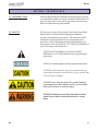
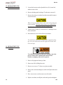
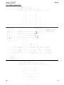
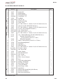
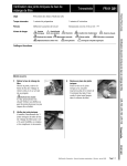
Henny Penny
Hand Breader/Sifter
Model HB-121
TECHNICAL MANUAL
HB-121
TABLE OF CONTENTS
Section
Page
Section 1. MAINTENANCE .....................................................................................................
1-1. Introduction ......................................................................................................
1-2. Safety ..............................................................................................................
1-3. Replacement of Belt .........................................................................................
1-4. Replacement of Mandrel ...................................................................................
1-5. Replacement of Motor ......................................................................................
1-6. Replacement of Switch .....................................................................................
1-7. Replacement of Rod End Bearing .....................................................................
1-8. Replacement of Push Rod Bearing ....................................................................
1-9. Replacement of Sifter Bearing ...........................................................................
1-10. Wiring Diagrams ...............................................................................................
1-1
1-1
1-1
1-2
1-2
1-3
1-4
1-5
1-6
1-6
1-7
Section 2. PARTS INFORMATION ..........................................................................................
2-1. Introduction ......................................................................................................
2-2. Genuine Parts ...................................................................................................
2-3. How to Find Parts ............................................................................................
2-4. How to Order Parts .........................................................................................
2-5. Prices ...............................................................................................................
2-6. Delivery ...........................................................................................................
2-7. Warranty ..........................................................................................................
2-8. Recommended Spare Parts for Distributors .......................................................
2-1
2-1
2-1
2-1
2-1
2-1
2-1
2-1
2-1
FM06-020
Revised 07-16-07
206
i
HB-121
SECTION 1. MAINTENANCE
1-1. INTRODUCTION
Electrical and mechanical components which may require servicing
are contained beneath the cover plate assembly. Outlined below are
step by step procedures when replacing parts becomes necessary.
Refer to exploded drawing in this manual.
1-2. SAFETY
The only way to ensure safe operation of the Henny Penny Hand
Breader/Sifter is to fully understand the proper installation,
operation, and maintenance procedures. The instructions in this
manual have been prepared to aid you in learning the proper
procedures. Where information is of particular importance or is
safety related, the words NOTICE, CAUTION or WARNING are
used. Their usage is described below:
SAFETY ALERT SYMBOL is used with DANGER,
WARNING, or CAUTION which indicates a personal injury
type hazard.
NOTICE is used to highlight especially important information.
CAUTION used without the safety alert symbol indicates
a potentially hazardous situation which, if not avoided, may
result in property damage.
CAUTION used with the safety alert symbol indicates
a potentially hazardous situation which, if not avoided,
may result in minor or moderate injury.
WARNING indicates a potentially hazardous situation
which, if not avoided, could result in death or serious
injury.
203
1-1
HB-121
1-3. REPLACEMENT OF
BELT
1. Remove all equipment (breading lugs, back splash, dip pot,
etc.) from top of unit.
2. Remove top (28) by lifting from unit.
3. Using a #2 Phillips screwdriver, remove two screws (17) from
cover plate assembly (16), and slide cover plate assembly out
towards the sifter basket.
4. Using a 1/2” wrench, loosen the hex nuts on the adjustable foot
(10) so that the motor (8) can be moved to loosen the belt (1).
5. Replace belt and adjust tension.
Proper tension is achieved when belt deflects approximately
1/2” (12.7 mm).
1-4. REPLACEMENT OF
MANDREL
To avoid electrical shock or property damage, move the
power switch to OFF and disconnect main circuit
breaker, or unplug cord at wall receptacle.
1. Remove all equipment from top of unit.
2. Remove top (28) by lifting from unit.
3. Remove two screws (17) from cover plate assembly (16) and
slide assembly out towards the sifter basket.
1-2
203
HB-121
1-4. REPLACEMENT OF
MANDREL (Continued)
4. Loosen hex nuts on the adjustable foot (10), move motor,
and loosen belt. Remove belt.
5. Using a 5/16" Allen wrench, remove set screw (62) from
driven pulley and remove pulley (53).
6. Turn mandrel shaft (52) until the eccentric (49) and rod end
bearing (46) are accessible.
7. Remove shoulder screw (51) and washers (48-43) and
allow rod end bearing (46) and push rod assembly (44) to
fall free.
8. Remove four bolts (5) holding mandrel to mounting
bracket and remove.
9. Remove eccentric (49) and eccentric spacer (57) by moving
eccentric clockwise.
The eccentric has left hand threads. Move the eccentric
clockwise or threads of eccentric could be damaged.
1-5. REPLACEMENT OF
MOTOR
To avoid electrical shock or property damage, move the
power switch to OFF and disconnect main circuit
breaker, or unplug cord at wall receptacle.
1. Remove all equipment from top of unit.
2. Remove top (28) by lifting from unit.
3. Remove two screws (17) from cover plate assembly
(16) and slide assembly out towards the sifter basket.
4. Remove nut (50) from cord clamp (26), and pull cord from
clamp.
203
1-3
HB-121
1-5. REPLACEMENT OF
MOTOR (Continued)
5. Loosen the hex nuts on the adjustable foot (10), loosen belt,
and then remove belt.
6. Remove the hinge pin from hinge (7) and remove motor (8).
7. Remove the wiring cover plate from the motor and disconnect
wires from motor.
When wiring new motor leads, refer to the wiring diagram
in this manual. The motor must rotate in a counterclockwise direction, or damage to the unit could result.
8. Transfer bolts (5), nuts (2), lockwashers (3), and hinge to new
motor and install.
9. Reassemble in reverse order of above procedures.
To avoid loose connections and possible component damage, wire nut connections must be tight and secured with
electrical tape.
1-6. REPLACEMENT OF
SWITCH
To avoid electrical shock or property damage, move the
power switch to OFF and disconnect main circuit
breaker, or unplug cord at wall receptacle.
1. Remove all equipment from top of unit.
2. Remove top (28) by lifting from unit.
3. Remove two screws (17) from cover plate assembly.
4. Remove the switch mounting nut, switch on/off plate and switch
guard.
5. Place wires on new switch exactly as on old switch.
6. Replace switch nut, on/off plate, and switch guard, and tighten.
1-4
203
HB-121
1-7. REPLACEMENT OF
ROD END BEARING
To avoid electrical shock or property damage, move the
power switch to OFF and disconnect main circuit
breaker, or unplug cord at wall receptacle.
1. Remove all equipment from top of unit.
2. Remove top (28) by lifting from unit.
3. Remove two screws (17) from cover plate assembly (16) and
slide assembly out towards the sifter basket.
4. Turn mandrel shaft (52) until eccentric (49) and rod end bearing
(46) are accessible.
5. Remove shoulder screw (51), nut and washers (48-43), and
allow rod end bearing (46) and push rod assembly (44) to fall
free.
6. Remove spring retainer (38) and lift push rod (44) off basket
holder (39).
7. Remove push rod assembly from unit and measure the distance
from the end of the rod end bearing (46) to the locking nut
(45).
8. Using two 9/16” wrenches, loosen locking nut (45) and
unthread rod end bearing from push rod (44).
9. Install locking nut (45) to new rod end bearing in same position
as old rod end bearing.
10. Snug locking nut and install push rod assembly to basket holder
(39) and eccentric (49), and tighten with 9/16” wrench.
203
1-5
HB-121
1-8. REPLACEMENT OF
PUSH ROD BEARING
To avoid electrical shock or property damage, move the
power switch to OFF and disconnect main circuit
breaker, or unplug cord at wall receptacle.
1. Remove all equipment from top of unit.
2. Remove spring retainer (38) from basket holder (39).
3. Lift end of push rod (44) from basket holder.
4. Replace push rod bearing (42).
1-9. REPLACEMENT OF
SIFTER BEARING
To avoid electrical shock or property damage, move the
power switch to OFF and disconnect main circuit
breaker, or unplug cord at wall receptacle.
1. Remove all equipment from top of unit.
2. Remove spring retainer (38) from basket holder (39).
3. Lift end of push rod (44) from basket holder.
4. Remove basket (40-41) and basket holder (39) from unit.
5. Replace sifter bearing (37).
1-6
203
HB-121
1-10. WIRING DIAGRAMS
203
1-7
HB-121
LIMITED WARRANTY FOR HENNY PENNY EQUIPMENT
Subject to the following conditions, Henny Penny Corporation makes the following limited warranties to the original
purchaser only for Henny Penny appliances and replacement parts:
NEW EQUIPMENT: Any part of a new appliance, except baskets, lamps, and fuses, which proves to be defective in
material or workmanship within two (2) years from date of original installation, will be repaired or replaced without
charge F.O.B. factory, Eaton, Ohio, or F.O.B. authorized distributor. Baskets will be repaired or replaced for ninety (90)
days from date of original installation. Lamps and fuses are not covered under this Limited Warranty. To validate this
warranty, the registration card for the appliance must be mailed to Henny Penny within ten (10) days after installation.
FILTER SYSTEM: Failure of any parts within a fryer filter system caused by the use of the non-OEM filters or
other unapproved filters is not covered under this Limited Warranty.
REPLACEMENT PARTS: Any appliance replacement part, except lamps and fuses, which proves to be defective in
material or workmanship within ninety (90) days from date of original installation will be repaired or replaced without
charge F.O.B. factory, Eaton, Ohio, or F.O.B. authorized distributor.
The warranty for new equipment covers the repair or replacement of the defective part and includes labor charges and
maximum mileage charges of 200 miles round trip for a period of one (1) year from the date of original installation.
The warranty for replacement parts covers only the repair or replacement of the defective part and does not include any
labor charges for the removal and installation of any parts, travel, or other expenses incidental to the repair or replacement of
a part.
EXTENDED FRYPOT WARRANTY: Henny Penny will replace any frypot that fails due to manufacturing or workmanship
issues for a period of up to seven (7) years from date of manufacture. This warranty shall not cover any frypot that fails due to
any misuse or abuse, such as heating of the frypot without shortening.
0 TO 3 YEARS:
During this time, any frypot that fails due to manufacturing or workmanship issues will
be replaced at no charge for parts, labor, or freight. Henny Penny will either install a new frypot at no cost or
provide a new or reconditioned replacement fryer at no cost.
3 TO 7 YEARS:
During this time, any frypot that fails due to manufacturing or workmanship issues will
be replaced at no charge for the frypot only. Any freight charges and labor costs to install the new frypot as
well as the cost of any other parts replaced, such as insulation, thermal sensors, high limits, fittings, and
hardware, will be the responsibility of the owner.
Any claim must be presented to either Henny Penny or the distributor from whom the appliance was purchased. No
allowance will be granted for repairs made by anyone else without Henny Penny’s written consent. If damage occurs during
shipping, notify the sender at once so that a claim may be filed.
THE ABOVE LIMITED WARRANTY SETS FORTH THE SOLE REMEDY AGAINST HENNY PENNY FOR ANY BREACH
OF WARRANTY OR OTHER TERM. BUYER AGREES THAT NO OTHER REMEDY (INCLUDING CLAIMS FOR ANY INCIDENTAL OR CONSEQUENTIAL DAMAGES) SHALL BE AVAILABLE.
The above limited warranty does not apply (a) to damage resulting from accident, alteration, misuse, or abuse; (b) if the
equipment’s serial number is removed or defaced; or (c) for lamps and fuses. THE ABOVE LIMITED WARRANTY IS EXPRESSLY IN LIEU OF ALL OTHER WARRANTIES, EXPRESS OR IMPLIED, INCLUDING MERCHANTABILITY AND FITNESS, AND ALL OTHER WARRANTIES ARE EXCLUDED. HENNY PENNY NEITHER ASSUMES NOR AUTHORIZES ANY
PERSON TO ASSUME FOR IT ANY OTHER OBLIGATION OR LIABILITY.
Revised 01/01/07
1-8
207
HB-121
SECTION 2. PARTS INFORMATION
2-1. INTRODUCTION
This section identifies and lists the replaceable parts of the Henny
Penny HB-121 Hand Breader/Sifter.
2-2. GENUINE PARTS
Use only genuine Henny Penny parts in your unit. Using a part of
lesser quality or substitute design may result in unit damage or
personal injury.
2-3. HOW TO FIND PARTS
To find items you want to order from the Parts List, proceed as
follows:
1. Refer to the exploded drawing in this section to identify the part
needed.
2. Use the item number from the exploded drawing to locate the
corresponding part in the parts list in this section. In this list will
be the Henny Penny part number and description of the part.
2-4. HOW TO ORDER PARTS
Once the part you want to order has been found in the Part List,
write down the following information:
1. From the exploded drawing and Parts List (Sample)
Item Number
37
Part Number
15232
Description
Sifter Bearing
2. From the data plate (Sample)
Product Number
HB121.0
Serial Number
00100
Voltage
120 V
2-5. PRICES
Your distributor has a price parts list and will be glad to inform you
of the cost of yours parts order.
2-6. DELIVERY
Commonly replaced items are stocked by your independent Henny
Penny distributor and will be sent out when your order is received.
Other parts will be ordered by the distributor from Henny Penny
Corporation. Normally, these will be sent to your distributor within
three working days.
2-7. WARRANTY
All replacement parts (except lamps and fuses) are covered under
warranty for 90 days against manufacturing defects and workmanship. If damage occurs during shipping, notify the carrier at once so
that a claim may be properly filed. Refer to the warranty in this
manual for other rights and limitations.
3-7.
Recommended replacement parts, stocked by your distributor, are
indicated with √ in the parts lists. Please use care when ordering
recommended parts, because all voltages and variations are
marked. Distributors should order parts based upon common
voltages and equipment sold in their territory.
206
RECOMMENDED
SPARE PARTS FOR
DISTRIBUTORS
2-1
HB-121
2-2
103
HB-121
HAND BREADER/SIFTER HB-121
No.
Part No.
√ 1
15254
Belt
2
3
4
4
5
6
7
√ 8
√ 8
√ 8
NS01-003
LW01-004
15261
63108
SC01-026
WA01-001
15269
63106
63107
14300
63105
63108
15269
9
NS02-002
10
15256
11
SC01-002
12
NS02-001
13
15884
14
15230
15
15700
15
74519
16
15889
15597
17
SC04-003
18
15349
19
15701
19
74415
20
15300
21
15252
22
15560
√ 23
22195
24
15115
25
15716
26
EF02-032
27
15880
27
15881
27
15944
28
15900
29
15253
30
15241
31
NS03-003
32
15227
32
15352
33
15875
33
15876
34
NS02-006
35
15228
36
SC01-015
37
15232
38
15233
√ recommended parts
707
Description
Nut (5/16-18)
Lockwasher (5/16)
Sheave Driver Pulley (1.75 OD-1/2” Bore) - 120 V units
Sheave Driver Pulley (2.00 OD-1/2” Bore) - 240 V units
Screw (5/16-18 x 3/4)
Washer (5/16 Flat)
Hinge
Motor - 120 V-60 Hz (1/4 hp - CW rotation)
Motor - 240 V-50 Hz (1/4 hp - CW rotation)
Motor And Hinge Kit (240 volt units built before 10-13-00)
Motor - 120/240 V-50/60 Hz
Sheave, Driver
Hinge
Nut (1/4-20 Hex Keps)
Adjustment Foot Assembly
Screw (#10-32 x 1/2" Truss Head)
Nut (#10-32 Hex Keps)
Partition
Instructions Decal
Switch Cord Assembly
Cord - AUS Power
Cover Plate Assembly
Wiring Diagram Decal
Screw (#8-32 x 3/8 PH Pan Head)
Motor Spacers
Cord w/Plug (7’long, Type 16/3 SJ)
Cord - Sub Assy AUS
Dip Pot
Dip Pot Holder
Slide - Cover
Switch
Lug Plug
Breading Lug
Clamp - Cord
Bin and Frame - Right Hand
Bin and Frame - Left Hand
Bin and Frame-K-Mart - Left Hand
Top
Tray Rack
Pan Support
Nut, Wing (#10-24)
Gusset - Left
Gusset - Right
Back Splash - Left
Back Splash - Right
Nut (# 10-24 Hex Keps)
Basket Hanger
Carriage Bolt (#10-24 x 1/2)
Sifter Bearing
Spring - Retainer
Qty.
1
8
8
1
1
8
8
1
1
1
1
1
1
1
10
1
2
2
1
1
1
1
1
1
2
2
1
1
1
1
2
1
2
2
1
1
1
1
1
1
1
4
1
1
1
1
3
1
3
1
1
2-3
HB-121
HAND BREADER/SIFTER HB-121
No.
√
√
√
√
√
40
41
42
43
44
45
46
47
48
48
49
49
50
51
52
52
53
54
55
56
57
57
58
59
60
61
62
63
64
65
66
67
68
69
70
√ 71
72
73
Part No.
15247
15281
15231
LW0l-001
15260
NS01-020
15346
15702
14083
26386
14083
66162
NS02-006
SC01-069
14083
67190
66161
21180
15170
15246
12140
12176
14083
(use 14083)
EF02-009
15302
22197
EF02-010
15163
15439
15888
26534
EF02-047
15891
26533
15887
EF02-016
15624
05019
15895
Description
Basket Wall
Basket Bottom
Bearing Push Rod
Lockwasher - 3/8”
Push Rod
Nut (3/8-24)
Rod End - Bearing
Guard - Drive
Kit - HB-120/HB-121 - Mandrel 5/8 (SN: KC0404001 & below)
Spacer Foot (SN: KC0404002 & above)
Kit - HB-120/HB-121 - Mandrel 5/8 (SN: KC0404001 & below)
Eccentric (SN: KC0404002 & above)
Nut - Clamp/Ground
Bolt - Hex (3/8-16 x 1-1/2”)
Kit - HB-120/HB-121 - Mandrel 5/8 (SN: KC0404001 & below)
Assy - Shaft and Bearings (SN: KC0404002 & above)
Qty.
1
1
1
1
1
1
1
1
1
1
1
1
6
1
1
1
Shaft(SN: KC0404002 & above)
(SN: KC0404001 & below use 14083)
1
Pillow Block Assembly
Sheave - Driven (Pulley, 8.00 O.D. x 1/2' Bore)
Drive Mounting Bracket
Dip Basket
Plastic Drip Tray
2
1
1
1
1
1
1
1
1
1
1
1
1
1
2
1
2
2
2
1
2
1
4
Kit - HB-120/HB-121 - Mandrel 5/8 (SN: KC0404001 & below)
Eccentric - Spacer
Nut - Hex Switch
Guard - Switch
Plate On/Off Switch
Nut - Switch
Key - 3/16" x 1"
Panel - Access - Bottom
Boot
Caster Unit (without brake)
Bushing - Strain Relief
Boot Clamp - 2 Hole
Caster Unit (Brake)
Boot Clamp - 1 Hole
Strain Relief
Microswitch (Canada Only) (Not Shown)
Bun Pan (Not Shown)
Bin Corners (Not Shown)
√ recommended parts
2-4
206