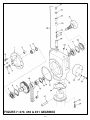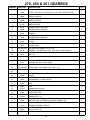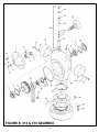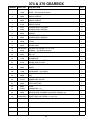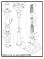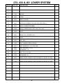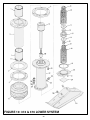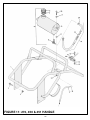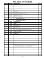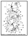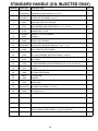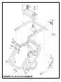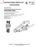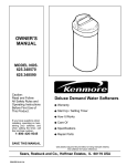
1
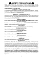
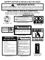
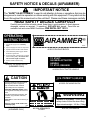
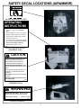
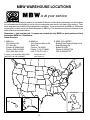
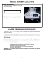
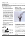
Operator's
Safety
and
Service
Manual
RAMMERS
It is the OWNER'S RESPONSIBILITY to communicate information on the
SAFE USE and OPERATION of this machine to the operators!
MBW INC.
250 HARTFORD ROAD P.O. BOX 440
SLINGER, WI 53086-0440
PHONE: (262) 644-5234 FAX (262) 644-5169
MBW CORPORATE INTERNET ADDRESS
E-MAIL: [email protected]
L12219 / 06.01
MBW Inc 2001
Printed in U.S.A.
IN ENGLAND:
MBW (UK) LIMITED
Bradley Fold Trading Estate Unit 6
Radcliffe Moor Road
Bolton BL2 6RT
Phone: 01204 387784 FAX: 01204 387797
WEB SITE: www.mbw.com
TABLE OF CONTENTS
SAFETY PRECAUTIONS . . . . . . . . . . . . . . . . . . . . . . . . . . . .
1
SAFETY NOTICE & DECALS . . . . . . . . . . . . . . . . . . . . . . . . .
2
SAFETY DECAL LOCATIONS . . . . . . . . . . . . . . . . . . . . . . . .
5
WARRANTY . . . . . . . . . . . . . . . . . . . . . . . . . . . . . . . . . . . . . . .
11
MBW WAREHOUSE LOCATIONS . . . . . . . . . . . . . . . . . . . .
12
RAMMER SPECIFICATIONS . . . . . . . . . . . . . . . . . . . . . . . . .
13
SERIAL NUMBER LOCATION . . . . . . . . . . . . . . . . . . . . . . . .
14
PARTS ORDERING PROCEDURE . . . . . . . . . . . . . . . . . . . .
14
PRE-OPERATING INSTRUCTIONS . . . . . . . . . . . . . . . . . .
15
OPERATING INSTRUCTIONS . . . . . . . . . . . . . . . . . . . . . . . .
17
PERIODIC MAINTENANCE . . . . . . . . . . . . . . . . . . . . . . . . . .
18
DISASSEMBLY . . . . . . . . . . . . . . . . . . . . . . . . . . . . . . . . . . . . .
20
ASSEMBLY . . . . . . . . . . . . . . . . . . . . . . . . . . . . . . . . . . . . . . . .
24
KITS & TORQUE CHART . . . . . . . . . . . . . . . . . . . . . . . . . . . .
25
REPLACEMENT AND TOLERANCE CHART . . . . . . . . . . .
26
270, 450 & 451 GEARBOX . . . . . . . . . . . . . . . . . . . . . . . . . .
27
374 & 376 GEARBOX . . . . . . . . . . . . . . . . . . . . . . . . . . . . . . .
29
270, 450 & 451 LOWER SYSTEM . . . . . . . . . . . . . . . . . . . . .
31
374 & 376 LOWER SYSTEM . . . . . . . . . . . . . . . . . . . . . . . . .
33
270, 450 & 451 HANDLE . . . . . . . . . . . . . . . . . . . . . . . . . . . .
35
STANDARD HANDLE (OIL INJECTED RAMMERS) . . . . . .
37
374 & 376 HANDLE . . . . . . . . . . . . . . . . . . . . . . . . . . . . . . . .
39
LO-PROFILE HANDLE . . . . . . . . . . . . . . . . . . . . . . . . . . . . .
41
LO-PROFILE HANDLE (OIL INJECTED RAMMERS) . . . .
43
AIRAMMER HANDLE . . . . . . . . . . . . . . . . . . . . . . . . . . . . . . .
45
ROBIN ENGINE ASSEMBLY . . . . . . . . . . . . . . . . . . . . . . . . .
47
ROBIN OIL INJECTED ENGINE ASSEMBLY . . . . . . . . . . .
49
LO-PROFILE ROBIN ENGINE ASSEMBLY . . . . . . . . . . . .
51
AIRAMMER MOTOR ASSEMBLY . . . . . . . . . . . . . . . . . . . . .
53
i
SAFETY PRECAUTIONS
READ AND STUDY THE FOLLOWING SAFETY INFORMATION BEFORE
ATTEMPTING TO OPERATE THIS EQUIPMENT. IN ADDITION, ENSURE THAT EVERY
INDIVIDUAL WHO OPERATES OR WORKS WITH THIS EQUIPMENT IS FAMILIAR
WITH THESE SAFETY PRECAUTIONS.
WARNING - LETHAL EXHAUST GAS!
An internal combustion engine discharges carbon monoxide, a poisonous, odorless
invisible gas. Death or serious illness may result if inhaled. Operate only in an area with
good ventilation, NEVER IN A CONFINED AREA!
WARNING - DANGEROUS FUELS!
Use extreme caution when storing, handling and using fuels - they are highly volatile and
explosive in vapor state. Do not add fuel while engine is running. Stop and cool the engine
before adding fuel. DO NOT SMOKE!
SAFETY GUARDS
It is the owner's responsibility to ensure ALL GUARDS AND SHIELDS remain in place.
IGNITION SYSTEMS
Breakerless, magneto and battery ignition systems CAN CAUSE SEVERE ELECTRICAL
SHOCKS. Avoid contacting these units or their wiring.
SAFE DRESS
DO NOT WEAR loose clothing, rings, wristwatches, etc., near machinery.
NOISE PROTECTION
Wear O.S.H.A. specified hearing protection devices.
FOOT PROTECTION
Wear O.S.H.A. specified steel tip safety shoes.
HEAD PROTECTION
Wear O.S.H.A. specified safety helmets.
EYE PROTECTION
Wear O.S.H.A. specified eye shields, safety glasses, and sweat bands.
OPERATOR
Keep children and bystanders off and away from the equipment.
REFERENCES
For details on safety rules and regulations in the United States, contact your local
Occupational Safety and Health Administration (O.S.H.A.) office. Equipment operated in
other countries must be operated and serviced in accordance and compliance with any
and all safety requirements of that country.The publication of these safety precautions is
done for your information. MBW Inc. does not by the publication of these precautions,
imply or in any way represent that these are the sum of all dangers present near MBW
equipment. If you are operating MBW Inc. equipment, it is your responsibility to insure that
such operation is in full accordance with all applicable safety requirements and codes. All
requirements of the United States Federal Occupational Safety and Healthy Administration
Act must be met when operated in areas that are under the jurisdiction of that United States
Department.
1
SAFETY NOTICE & DECALS (EC10D ONLY)
IMPORTANT NOTICE
The SAFETY ALERT SYMBOL" is used to call attention to items or operations that may be
dangerous to machine operators or others working with this equipment. The symbol can be
found throughout this manual and on the unit itself. Please read these messages carefully.
READ SAFETY DECALS CAREFULLY
Carefully read and follow all safety decals. Keep them in good condition. If decals become
damaged, replace as required. If repainting, REPLACE ALL decals. Decal Kits are
available from authorized MBW Distributors.USE DECAL SET 12101
CAUTION
WARNING
Machine is top heavy. Attach proper
safety chains to this bar when lifting.
Approximate weight: 160 lbs. (73 kg)
Model R540 only:
205 lbs. (93 kg)
13531
#13531 ON HANDLE
FUEL MIXTURE
(After break in period)
Mix 50 parts gasoline to 1
part 2-cycle engine oil
(50:1).
#01326, SPRINGBOX COVER
Read the Operating Instructions before
operating this piece of equipment.
Keep unauthorized and untrained
people away from this equipment.
ROTATING & MOVING PARTS! Make
sure all guards and safety devices are in
place.
DO NOT RUN this machine in an enĆ
closed area. The engine produces carĆ
bon monoxide, a POISONOUS GAS.
Wear approved hearing protection, foot
protection, eye protection and head
protection.
SHUT OFF the engine before servicing,
cleaning or adding fuel.
Failure to comply could result in seriĆ
ous bodily injury.
13483
AIR CLEANER INSTRUCTIONS
CLEAN ELEMENT DAILY. MORE OFTEN UNDER DUSTY CONDITIONS.
TAP ELEMENT LIGHTLY ON A FLAT SURFACE - IF DUST DOES NOT
DROP OFF EASILY OR IF ELEMENT IS BENT OR CRUSHED...................
REPLACE IT!
WARNING: DO NOT OPERATE ENGINE WITHOUT AIR CLEANER
ELEMENT - INTERNAL DAMAGE WILL RESULT!
01067
#13483, ON FUEL TANK
(GASOLINE ONLY)
#01067, ON FUEL TANK
06079
#06079, ON AIR CLEANER
OPERATING
INSTRUCTIONS
1. Open fuel valve.
2. Choke engine. A warm engine may not
need to be choked.
3. Set throttle at idle position.
01064
4. Pull starter rope.
B
#01064 ON ENGINE
SHROUD
5. After starting: open choke.
6. For normal usage set throttle fully open.
7. To stop: Return throttle to idle position,
press Stop" button, close fuel valve.
01436
#01436, ON FUEL TANK
(GASOLINE ONLY)
#14770, ON HANDLE
(RATCHET STYLE
THROTTLE ONLY)
2
#01060, ON AIR CLEANER
SAFETY NOTICE & DECALS (EC12D ONLY)
IMPORTANT NOTICE
The SAFETY ALERT SYMBOL" is used to call attention to items or operations that may be
dangerous to machine operators or others working with this equipment. The symbol can be
found throughout this manual and on the unit itself. Please read these messages carefully.
READ SAFETY DECALS CAREFULLY
Carefully read and follow all safety decals. Keep them in good condition. If decals become
damaged, replace as required. If repainting, REPLACE ALL decals. Decal Kits are
available from authorized MBW Distributors.USE DECAL SET 14768
AIR CLEANER INSTRUCTIONS
CLEAN ELEMENT DAILY. MORE OFTEN UNDER DUSTY CONDITIONS.
TAP ELEMENT LIGHTLY ON A FLAT SURFACE - IF DUST DOES NOT
DROP OFF EASILY OR IF ELEMENT IS BENT OR CRUSHED...................
REPLACE IT!
WARNING: DO NOT OPERATE ENGINE WITHOUT AIR CLEANER
ELEMENT - INTERNAL DAMAGE WILL RESULT!
06079
#06079, ON AIR CLEANER
#14774, ON OIL TANK
CAP
UNLEADED
GASOLINE
14781
#14781, ON FUEL TANK
01064
B
#01064 ON ENGINE
WARNING
Machine is top heavy. Attach proper
safety chains to this bar when lifting.
Approximate weight: 160 lbs. (73 kg)
14769
#14769 ON HANDLE
OPERATING
INSTRUCTIONS
1. Check fuel level
2. Open fuel valve.
3. Set throttle at idle position.
4. Choke engine. A warm engine may not need
to be choked.
5. Pull starter rope
6. After starting, open choke gradually and let
engine warm up at idle.
7. To start compacting: open throttle fully.
8. To stop: return throttle to idle and allow engine
to run for a few minutes before turning off.
9. Turn engine switch to off and close fuel valve.
14773
CAUTION
Read the Operating Instructions before
operating this piece of equipment.
Keep unauthorized and untrained
people away from this equipment.
ROTATING & MOVING PARTS! Make
sure all guards and safety devices are in
place.
DO NOT RUN this machine in an enĆ
closed area. The engine produces carĆ
bon monoxide, a POISONOUS GAS.
Wear approved hearing protection, foot
protection, eye protection and head
protection.
SHUT OFF the engine before servicing,
cleaning or adding fuel.
Failure to comply could result in seriĆ
ous bodily injury.
13483
#14773 ON FUEL TANK
(GASOLINE ONLY)
#13483, ON FUEL TANK
(GASOLINE ONLY)
3
#01326, SPRINGBOX COVER
T
RUN
H
R
O
T
T
L
E IDLE
14770
#14770, ON HANDLE
(RATCHET STYLE
THROTTLE ONLY)
SAFETY NOTICE & DECALS (AIRAMMER)
IMPORTANT NOTICE
The SAFETY ALERT SYMBOL" is used to call attention to items or operations that may be
dangerous to machine operators or others working with this equipment. The symbol can be
found throughout this manual and on the unit itself. Please read these messages carefully.
READ SAFETY DECALS CAREFULLY
Carefully read and follow all safety decals. Keep them in good condition. If decals become
damaged, replace as required. If repainting, REPLACE ALL decals. Decal Kits are
available from authorized MBW Distributors.USE DECAL SET 12101
OPERATING
INSTRUCTIONS
1. Connect air supply hose. Use Safety
Clips.
AIRAMMER ®
12213
2. Open air supply hose valve on compressor.
#12213 ON VALVE BLOCK
3. Squeeze actuator handle to start machine.
4. Check Airammer pressure gage. Needle
should be in green area.
5. On uneven areas, pushing down on handle
will aid climbing ability. Do not bear down
with excessive weight on machine.
TO START:
SQUEEZE ACTUATOR
HANDLE
TO STOP: RELEASE
6. Release actuator handle to stop.
13534
#13534, ON VALVE BLOCK
(AIRAMMER ONLY)
13538
#13538 ON ACTUATOR HANDLE
CAUTION
U.S. PATENT 5,340,233
13535
Read the Operating Instructions before
operating this piece of equipment.
#13535 ON VALVE BLOCK
Keep unauthorized and untrained
people away from this equipment.
ROTATING & MOVING PARTS! Make
sure all guards and safety devices are in
place.
WARNING
Wear approved hearing protection, foot
protection, eye protection and head
protection.
Machine is top heavy. Attach proper
safety chains to this bar when lifting.
Approximate weight: 160 lbs. (73
kg)
14769
SHUT OFF the motor before servicing or
cleaning.
Failure to comply could result in seriĆ
ous bodily injury.
12203
#12203, ON VALVE BLOCK
(AIRAMMER ONLY)
#01326, SPRINGBOX
COVER
4
#14769, ON HANDLE
SAFETY DECAL LOCATIONS (EC10D ONLY)
FUEL MIXTURE
(After break in period)
Mix 50 parts unleaded
gasoline to 1 part
2-stroke engine oil
(50:1).
01067
#01067, ON FUEL TANK
OPERATING
INSTRUCTIONS
1.
Open fuel valve.
2.
Choke engine. A warm engine may not
need to be choked.
3.
Set throttle at idle position.
4.
Pull starter rope.
5.
After starting: open choke.
6.
For normal usage set throttle fully open.
7.
To stop: Return throttle to idle position,
press Stop" button, close fuel valve.
01436
#01436, ON FUEL TANK
CAUTION
Read the Operating Instructions before operating this
piece of equipment.
Keep unauthorized and untrained people away from this
equipment.
ROTATING & MOVING PARTS! Make sure all guards and
safety devices are in place.
DO NOT RUN this machine in an enclosed area. The
engine produces carbon monoxide, a POISONOUS GAS.
Wear approved hearing protection, foot protection, eye
protection and head protection.
SHUT OFF the engine before servicing, cleaning or addĆ
ing fuel.
Failure to comply could result in serious bodily injury.
13483
#13483, ON FUEL TANK
(GASOLINE ONLY)
WARNING
Machine is top heavy. Attach proper safety chains to this bar
when lifting.
Approximate weight:
Model R540 only:
160 lbs. (73 kg)
205 lbs. (93 kg)
13531
#13531 ON HANDLE
T
RUN
H
R
O
T
T
L
E IDLE
14770
#14770, ON HANDLE
(RATCHET STYLE
THROTTLE ONLY)
5
SAFETY DECAL LOCATIONS (CONT.)
#01326 SPRINGBOX COVER
01064
B
#01064 ON ENGINE
AIR CLEANER INSTRUCTIONS
CLEAN ELEMENT DAILY. MORE OFTEN UNDER DUSTY CONĆ
DITIONS. TAP ELEMENT LIGHTLY ON A FLAT SURFACE - IF
DUST DOES NOT DROP OFF EASILY OR IF ELEMENT IS BENT
OR CRUSHED................... REPLACE IT!
WARNING: DO NOT OPERATE ENGINE WITHOUT AIR
CLEANER
06079
ELEMENT - INTERNAL DAMAGE WILL RESULT!
#06079, ON AIR CLEANER
#01060, ON AIR CLEANER
6
SAFETY DECAL LOCATIONS (EC12D ONLY)
OPERATING
INSTRUCTIONS
1.
Open fuel valve.
2.
Choke engine. A warm engine may not
need to be choked.
3.
Set throttle at idle position.
4.
Pull starter rope.
5.
After starting: open choke.
6.
For normal usage set throttle fully open.
7.
To stop: Return throttle to idle position,
press Stop" button, close fuel valve.
01436
#01436, ON FUEL TANK
CAUTION
Read the Operating Instructions before operating this
piece of equipment.
Keep unauthorized and untrained people away from this
equipment.
ROTATING & MOVING PARTS! Make sure all guards and
safety devices are in place.
DO NOT RUN this machine in an enclosed area. The
engine produces carbon monoxide, a POISONOUS GAS.
Wear approved hearing protection, foot protection, eye
protection and head protection.
SHUT OFF the engine before servicing, cleaning or addĆ
ing fuel.
Failure to comply could result in serious bodily injury.
13483
#13483, ON FUEL TANK
(GASOLINE ONLY)
WARNING
Machine is top heavy. Attach proper
safety chains to this bar when lifting.
Approximate weight:
160 lbs. (73 kg)
14769
#14769 ON HANDLE
UNLEADED
GASOLINE
14781
#14781, ON FUEL TANK
01064
B
#01064, ON ENGINE
7
SAFETY DECAL LOCATIONS (CONT.)
AIR CLEANER INSTRUCTIONS
CLEAN ELEMENT DAILY. MORE OFTEN UNDER DUSTY CONĆ
DITIONS. TAP ELEMENT LIGHTLY ON A FLAT SURFACE - IF
DUST DOES NOT DROP OFF EASILY OR IF ELEMENT IS BENT
OR CRUSHED................... REPLACE IT!
WARNING: DO NOT OPERATE ENGINE WITHOUT AIR
CLEANER
06079
ELEMENT - INTERNAL DAMAGE WILL RESULT!
#06079, ON AIR CLEANER
#14774, ON OIL TANK CAP
T
RUN
H
R
O
T
T
L
E IDLE
14770
#14770, ON HANDLE
(RATCHET STYLE
THROTTLE ONLY)
#01326, SPRINGBOX COVER
8
SAFETY DECAL LOCATIONS (AIRAMMER)
#01326, SPRINGBOX COVER
OPERATING
INSTRUCTIONS
1. Connect air supply hose. Use Safety
Clips.
2. Open air supply hose valve on compressor.
3. Squeeze actuator handle to start machine.
4. Check Airammer pressure gage. Needle
should be in green area.
5. On uneven areas, pushing down on handle
will aid climbing ability. Do not bear down
with excessive weight on machine.
6. Release actuator handle to stop.
13534
#13534, ON VALVE BLOCK
(AIRAMMER ONLY)
CAUTION
Read the Operating Instructions before
operating this piece of equipment.
Keep unauthorized and untrained
people away from this equipment.
ROTATING & MOVING PARTS! Make
sure all guards and safety devices are in
place.
Wear approved hearing protection, foot
protection, eye protection and head
protection.
SHUT OFF the motor before servicing or
cleaning.
Failure to comply could result in seriĆ
ous bodily injury.
12203
#12203, ON VALVE BLOCK
(AIRAMMER ONLY)
WARNING
Machine is top heavy. Attach proper
safety chains to this bar when lifting.
Approximate weight:
160 lbs. (73 kg)
14769
#14769 ON HANDLE
9
SAFETY DECAL LOCATIONS (CONT.)
AIRAMMER ®
12213
#12213 ON VALVE BLOCK
U.S. PATENT 5,340,233
13535
#13535 ON VALVE BLOCK
TO START:
SQUEEZE ACTUATOR
HANDLE
TO STOP: RELEASE
13538
#13538 ON ACTUATOR HANDLE
10
WARRANTY
WARRANTY
THIS IS YOUR WARRANTY - PLEASE READ AND SAVE
1. MBW INC, Slinger Wisconsin, warrants each new machine against defects in material and workmanship
under normal use and service for a period of six (6) months. This warranty commences the first day the
machine is sold, assigned to a rental fleet, or otherwise put to first use.
2. The obligation under this warranty is limited to the replacement or repair of parts and/or machine at MBW
INC factory branches or at authorized MBW INC Distributors.
3. Machines altered or modified without MBW INC written consent voids this warranty. Misuse, negligence,
accidents or the operation of machines in any way other than recommended by MBW INC will void this
warranty. This warranty shall not apply to machines repaired by other than MBW INC factory branches or
authorized MBW INC Distributors.
4. This warranty includes labor on all MBW INC products. Labor must be performed at an authorized MBW INC
Distributor.
5. The cost of transportation and other expenses connected therewith are not covered by this warranty.
6. Written authorization for the return of merchandise under warranty must be obtained from MBW INC,
Slinger, Wisconsin. In England: MBW (UK) LIMITED, Bradley Fold Trading Estate Unit 6, Radcliffe Moor
Road, Bolton BL2 6RT.
7. MBW INC reserves the right to inspect and render final decision on each warranty case.
8. MBW INC reserves the right to improve or make product changes without incurring any obligation to
update, refit, or install the same on machines previously sold.
9. MBW INC is not responsible for any liability or damage or injury directly or indirectly from design, material or
operation of its products.
10. Warranty card must be returned to MBW INC, P.O. Box 440, Slinger, Wisconsin 53086-0440, within 10 days
after purchase, assignment to a rental fleet, or first use. In England: MBW (UK) LIMITED, Bradley Fold
Trading Estate Unit 6, Radcliffe Moor Road, Bolton BL2 6RT. Failure to return warranty card as specified
renders the warranty null and void.
11. Requests for warranty must be submitted in writing within 30 days after machine failure to MBW INC, P.O.
Box 440, Slinger, Wisconsin 53086-0440. In England: MBW (UK) LIMITED, Bradley Fold Trading Estate
Unit 6, Radcliffe Moor Road, Bolton BL2 6RT.
12. THE FOREGOING WARRANTY IS EXPRESSLY IN LIEU OF ALL OTHER WARRANTIES, EXPRESSED OR
IMPLIED, INCLUDING THE WARRANTIES OF MERCHANTABILITY AND FITNESS FOR USE, AND OF ALL
OTHER OBLIGATION OR LIABILITIES ON OUR PART, AND WE NEITHER ASSUME NOR AUTHORIZE ANY
OTHER PERSON TO ASSUME FOR US ANY OTHER LIABILITY OR WARRANTY IN CONNECTION WITH
THE SALE OR SERVICE OF ANY OF OUR PRODUCTS. LIKEWISE, THIS WARRANTY SHALL NOT APPLY
WITH RESPECT TO ENGINES, MOTORS AND OTHER COMPONENT PARTS PRODUCED BY OTHER
MANUFACTURERS AND USED ON MBW PRODUCTS, BUT SUCH ITEMS SHALL HAVE SUCH
WARRANTIES AS MAY BE PROVIDED BY THE MANUFACTURER THEREOF.
MBW INC.
250 HARTFORD ROAD P.O. BOX 440
SLINGER, WI 53086-0440
PHONE: (262) 644-5234 FAX (262) 644-5169
MBW CORPORATE INTERNET ADDRESS
E-MAIL: [email protected]
IN ENGLAND:
MBW (UK) LIMITED
Bradley Fold Trading Estate Unit 6
Radcliffe Moor Road
Bolton BL2 6RT
Phone: 01204 387784 FAX: 01204 387797
11
WEB SITE: www.mbw.com
MBW WAREHOUSE LOCATIONS
is at your service
MBW Inc. has established a network of reputable Distributors with trained mechanics and full facilities
for maintenance and rebuilding, and to carry an adequate parts stock in all areas of the country. Their
sales engineers are available for professional consultation. If you cannot locate an MBW Inc. Distributor
in your area, contact one of our Sales Branches or MBW Inc. The locations and phone numbers of the
Sales Branches are listed below.
Remember - you own the best. If repairs are needed use only MBW Inc. parts purchased from
Authorized MBW Inc. Distributors.
Sales Branches:
1. MBW Inc.
250 Hartford Rd.
P.O. Box 440
Slinger, WI 53086Ć0440
Phone: (262) 644Ć5234
FAX: (262) 644-5169
3. MBW (UK) LIMITED
Bradley Fold Trading Estate Unit 6
Radcliffe Moor Rd.
Bolton BL2 6RT
Phone: 01204 387784
FAX: 01204 387797
2. MBW Inc.
2341 Pomona Rincon Rd.
Suite 106
Corona, CA 92880
Phone: (714) 272Ć9989
FAX: (714) 272-9611
E-MAIL ON THE WORLD WIDE WEB
WEB SITE ON THE INTERNET
[email protected]
www.mbw.com
1
2
Great Britain
3
12
SPECIFICATIONS
R270R
R270ROI
R376R
R451R
GASOLINE POWERED RAMMERS: Robin EC10D, and Robin EC12, 4 hp (3kW)
UNITS
R270R
R270ROI
Operating Weight
lbs (kg)
142 (64)
160 (73)
Height
in (cm)
45 (114)
45 (114)
R374R
R376R
R450R
R451R
155 (70)
158 (72)
142 (64)
148 (67)
45Ć52 (114Ć132)
45Ć52 (114Ć132)
45 (114)
45 (114)
Width
in (cm)
17 (43)
17 (43)
17 (43)
17 (43)
17 (43)
17 (43)
Length
Shoe (W X L)
in (cm)
in
( )
(cm)
25.5 (65)
11 x 13
(28 x 33)
25.5 (65)
11 x 13
(28 x 33)
25.5 (65)
4 x 18
(10 x 46)
6)
25.5 (65)
6 x 18
(1 x 46)
(15
6)
25.5 (65)
11 x 13
(28 x 33)
25.5 (65)
13 x 15
(33 x 38)
Compaction Force
lbf (kN)/blow
3400 (15.1)
3400 (15.1)
4000 (17.8)
4050 (18)
4500 (20)
4550 (20.3)
Percussion Rate
blows/minute
600Ć650
600Ć650
550-600
550-600
600Ć650
600Ć650
Travel Speed
ft/min (m/min)
55 (16.8)
55 (16.8)
50 (15.3)
50 (15.3)
60 (18.3)
60 (18.3)
Compaction Depth
in (cm)
22 (56)
22 (56)
24 (61)
23 (58)
24 (61)
24 (61)
Compaction Area
sqft/h (sqm/h)
3025 (280)
3025 (280)
1000 (93)
1500 (139)
3300 (307)
3900 (362)
Engine Speed
rpm
4300
4400
4000
4000
4400
4400
Fuel Capacity
qts (L)
2.5 (2.4)
2.5 (2.4)
2.5 (2.4)
2.5 (2.4)
2.5 (2.4)
2.5 (2.4)
Oil Tank Capacity
pints (L)
N/A
1 (.47)
N/A
N/A
N/A
N/A
PNEUMATIC POWERED RAMMERS: TCS 66V, 4hp (3kW)
Operating Weight
lbs (kg)
125 (57)
N/A
N/A
N/A
125 (57)
130 (59)
Percussion Rate
blows/minute
650
N/A
N/A
N/A
650
650
Travel Speed
ft/min (m/min)
60 (18.3)
N/A
N/A
N/A
60 (18.3)
60 (18.3)
Compaction Area
sqft/h (sqm/h)
3300 (307)
N/A
N/A
N/A
3300 (307)
3900 (362)
Air Requirement
cfm / psi
75 / 110
N/A
N/A
N/A
75 / 110
75 / 110
Operating Speed
rpm
4500
N/A
N/A
N/A
4500
4500
13
SERIAL NUMBER LOCATION
RAMMER SERIAL NUMBER
1. Located on the top of the gearbox on the side
next to the filler plug.
(Write Serial Number in box.)
2. The serial number is also stamped on the top
of the gearbox in front of the breather boss.
PARTS ORDERING PROCEDURE
The Warranty is stated in this book on page 4. Failure to return Warranty Registration Card renders the
Warranty null and void.
An Operating Instructions and Parts Catalog for the engine is also furnished. Engine Parts may be ordered from
any authorized dealer. Refer to the Engine Operating Instructions and Parts Catalog for exploded view and parts
identifications.
PARTS ORDERING:
MBW Inc. parts are available worldwide and must be ordered through your local MBW Inc. Distributor. If you
cannot locate an MBW Inc. Distributor in your area, refer to page 5 of this Manual, locate the MBW Inc. Sales
Branch nearest you and call for assistance.
ALWAYS INCLUDE:
1. Model and Serial Number of Machine when ordering MBW Parts.
2. Engine Model and Serial Number when ordering Engine Components.
3. Item Part Number, Description and Quantity.
4. Company Name, Address, Zip Code, and Purchase Order Number.
5. Preferred method of shipping.
REMEMBER - you own the best. If repairs are needed use only MBW Inc. parts purchased from Authorized
MBW Inc. Distributors.
14
PRE-OPERATING INSTRUCTIONS
GASOLINE POWERED RAMMERS WITH ROBIN EC10 ENGINES ONLY:
FUEL SUPPLY - The gasoline powered engines on MBW Inc rammers use an oilĆgasoline mixture. For a
break in period of 8 hours, use a 20:1 gasoline to oil mixture. After breakĆin, use a 50:1 mixture. To obtain a 50:1
mixture, thoroughly mix 3/4 pt (355 ml) of a good grade of 2Ćcycle oil with 5 gal (19 L) of clean, fresh, Unleaded
gasoline in a clean, separate container.
NOTE: After breakĆin operation, engine exhaust should be clean (NO SMOKE).
Use of 4Ćcycle Motor Oils or Leaded Gasoline may cause varnishing or spark plug fouling.
AIR CLEANER - Check to ensure element is in good condition and properly installed.
OIL LEVEL - Check the Governor Chamber oil level by removing the Dip Stick. The oil mark should be about
5/16 in (8 mm) from the bottom of the Dip Stick. Add oil if required. For more information see Lubrication" under
PERIODIC MAINTENANCE," or the Robin EC10D Manual INSTRUCTIONS FOR USE".
FUEL FILTER - If clogged or damaged, replace.
GASOLINE POWERED RAMMERS WITH ROBIN EC12 ENGINES ONLY:
FUEL SUPPLY - The oil injected engines on gasoline powered MBW Inc rammers use an unleaded gasoline
mixture of 32:1 for a break in period. After running the machine for a time, check to see if the engine is consuming
2Ćcycle oil from the oil tank. If the engine is consuming oil from the tank, you can use just unleaded gasoline in the
fuel tank.
NOTE: After breakĆin operation, engine exhaust should be clean (NO SMOKE).
Use of 4Ćcycle Motor Oils or Leaded Gasoline may cause varnishing or spark plug fouling.
AIR CLEANER - Check to ensure element is in good condition and properly installed.
OIL LEVEL - Check the level of 2Ćcycle oil in the oil tank before starting. If required, add a good grade of
exclusive 2Ćcycle oil. For more information see Lubrication" under PERIODIC MAINTENANCE," or the Robin
EC12 Manual INSTRUCTIONS FOR USE."
OIL SENSOR - Check to ensure wire leads are connected. Make sure the mounting nut is tight. If sensor is
damaged replace.
FUEL FILTER - If clogged or damaged, replace.
Make sure hands, feet and clothing are at a safe distance from any moveable parts prior to starting, Also,
before starting, review related Safety Precautions listed on Page 1.
15
PNEUMATIC POWERED RAMMERS:
GOVERNOR - Do not disassemble the governor. The governor is guaranteed by the motor manufacturer for
the life of the motor if it is not abused. Tampering with the governor voids this warranty and may result in serious
injury or death.
LUBRICATION - Oil lubrication must be supplied to the pneumatic motor at all times during operation.
Operating the rammer without lubrication will cause premature wear and ultimately failure of the motor. Do not install
a lubricator on the rammer handle. Air lubrication system should supply 1/2 oz oil for every 8 hours of use.
COMPRESSED AIR SUPPLY - All MBW AIRAMMERS require a compressed air supply of at least 85 cfm
(cubic feet per minute) at 110 psi (pounds per square inch). The air supply must be provided on a continuous basis.
(i.e. Check the compressor pressure gauge while the rammer is running). Peak compaction performance will not
be achieved if the air supply is inadequate.
MOTOR ICING - If the rammer is operated for extended periods of time or is operated in high humidity
conditions, frost will form on the motor. This is normal and will not harm the motor. If the motor should freeze up"
from icing, allow it to thaw before continuing usage. Ensure that there is adequate oil supply to the motor.
Make sure hands, feet and clothing are at a safe distance from any moveable parts prior to starting, Also,
before starting, review related Safety Precautions listed on Page 1.
16
OPERATING INSTRUCTIONS
GASOLINE POWERED MODELS:
STARTING
For detailed instructions refer to EC10D or EC12 (oil
injected) Engine Manual.
Do not bear down (Body Weight Of Operator) on
the machine.
1. Open fuel valve.
2. Choke engine. When starting a warm engine,
choke may not be required.
3. After three passes, the rammer may have more
kick back. This is an indication that ideal
compaction is being reached.
3. Place thottle at idle position.
STOPPING
4. If engine is equipped with a switch, turn to the ON"
position.
5. Pull starter rope.
1. Whenever possible, allow the engine to idle before
stopping.
6.
2. Move the throttle to the idle position.
After the engine starts, open the choke. Let engine
warm up in the idle position for approximately one
minute.
3. Press the stop button on the side of the blower
housing, or turn the switch on the blower housing
to OFF"
4. Close fuel valve.
If the engine does not start after five or six pulls,
check the spark plug for carbon deposits.
STOP THE ENGINE BEFORE:
OPERATING
Adding fuel or oil.
1. After the engine warms up, open the throttle. For
normal operation, open the throttle fully.
Leaving equipment unattended, even if only for
a minute.
2. On uneven areas, pushing down on the handle will
aid climbing ability.
Making any repairs or adjustments.
PNEUMATIC POWERED MODELS:
STARTING
3. After three passes, the rammer may have more
kick back. This is an indication that ideal
compaction is being reached.
1. Connect the air compressor supply hose to the
airammer. USE SAFETY CLIPS.
2. Open the air supply hose valve on the compressor.
STOPPING
3. Squeeze the Airammer actuator handle.
1. Release the Airammer actuator handle. Close the
air supply valve on the compressor. Squeeze the
Airammer actuator handle to depressurize the air
supply hose before disconnecting the air hose.
OPERATING
1. Squeeze the Airammer actuator handle and check
the Airammer pressure gage. If the needle is not in
the green area check the compressor operation
and make sure there are no kinks in the air hose.
2. On uneven areas, pushing down on the handle will
aid climbing ability.
STOP THE MOTOR BEFORE:
Leaving equipment unattended, even if only for
a minute.
Do not bear down (Body Weight Of Operator) on
the machine.
Making any repairs or adjustments.
17
PERIODIC MAINTENANCE
GASOLINE ENGINES:
AIR CLEANER
ENGINE LUBRICATION: Robin EC12
oil injected
The rammer uses a dry type air cleaner element. Clean
the element by removing it and tapping it lightly on a flat
surface. Keep tapping until no dust comes off. The
element should be replaced if dust does not drop off
easily or if element becomes damaged.
1. The EC12 twoĆcycle engine is lubricated by the
twoĆcycle oil from a separate oil tank. Use a 32:1
gas to oil mixture for a breakĆin period of 8 hours.
After breakĆin, use only unleaded gasoline in the
fuel tank provided the engine is consuming oil from
the oil tank.
NOTE: Do not wash the element in any liquid or blow
dust off with compressed air. Do not tap element on a
sharp corner, it may damage the seal.
2. The oil tank is equipped with a filtering screen built
into the elbow on the bottom of the tank. This
should be replaced once a year or 300 hours,
whichever comes first. At this time, drain oil in tank
and test oil sensor. To do this, use a spark tester
and pull on the starter rope. If you get a spark, the
oil sensor is no good, replace.
SPARK PLUG
Remove and check the spark plug regularly. Clean or
replace if necessary. Set the spark plug gap according
to the tuneĆup specifications section. Reinstall the plug
and torque to 15Ć20 ft. lbs. (21Ć28 Nm).
MUFFLER
Check and clean the muffler exhaust hole regularly but
do not enlarge it.
NOTE: If the muffler exhaust hole is enlarged or holes
are drilled into the muffler the warranty is voided.
MEASURE GAP
WITH FEELER
GAUGE
TUNEĆUP SPECIFICATIONS
ROBIN EC10
FOR
1. Spark Plug Gap
Robin
NGK
BĆ4HS-0.024-0.028in
(0.6-0.7mm)
Champion UJ12-0.024-0.028in (0.6-0.7
mm)
2. Ignition Coil Air Gap
Robin
engine
points:
0.012-0.020in
(0.3-0.5mm)
ENGINE LUBRICATION: Robin EC10
3. Carburetor
Low speed adjusting screw, approximately one
turn counterclockwise.
1. The 2Ćcycle engine is lubricated by the oilĆgasoline
mixture. Use a 20:1 gas to oil mixture for a breakĆin
period of 8 hours. After breakĆin, use a 50:1 gas to
oil mixture. For a 50:1 mixture, mix 3/4 pint (12
ounces, 355 ml) of 2-cycle motor oil with 5 gallons
(19L) of lead-free gasoline.
TUNEĆUP SPECIFICATIONS
ROBIN EC12
FOR
2. The Robin 2Ćcycle engine also has oil in a separate
governor crankcase.
a. Remove the governor chamber dipstick which
is behind the muffler.
1. Spark Plug Gap
Robin
NGK
BM6A-0.024-0.028in.
(0.6-0.7mm)
Champion CJ8-0.024-0.028in. (0.6-0.7mm)
2. Ignition Coil Air Gap
Robin engine points: 0.012-0.020in (0.3-0.5
mm)
b. The oil level should be at the upper level which
is 0.31 in. (8mm) up from the bottom of the dipĆ
stick.
3. Carburetor
Low speed adjusting screw, approximately one
turn counterclockwise.
TORQUE SPECIFICATIONS
c. If oil is needed, add a good grade of Service
SF" SAE 10W-30 Motor Oil.
d. Also see the Robin Operating Instructions
and Parts List".
18
SPARK PLUG
FLYWHEEL
OIL DRAIN PLUG
OIL FILLER PLUG
15-20 ft lbs (21-28 Nm)
35 ft lbs (49 Nm)
10 ft lbs (14 Nm)
10 ft lbs (14 Nm)
PNEUMATIC MOTORS:
GOVERNOR
3. A high volume flow in line oiler is adequate. Do not
install a lubricator on the rammer handle.
4. Use a suitable air tool approved oil such as Exxon
Spinesstic 10, Atlantic Richfield Duro 55, Gulf
Gulfspin 10 or equivalent.
Do not disassemble the governor. The governor is
guaranteed by the motor manufacturer for the life of the
motor if it is not abused. Tampering with the governor
voids this warranty and may result in serious injury
or death. To remove the governor use the governor
wrench available from MBW or from an authorized TCS
dealer.
COMPRESSED AIR SUPPLY
MBW AIRAMMERS require an adequate compressed
air supply. The air supply must be provided on a
continuous basis. (i.e. Check the compressor pressure
gauge while the rammer is running).
MOTOR LUBRICATION
R270A, R450A, R451A: require at least 75 cfm
(cubic feet per minute) at 110 psi (pounds per
square inch).
Oil lubrication must be supplied to the pneumatic
motor at all times during operation. Operating the
rammer without lubrication will cause premature wear
and ultimately failure of the motor.
MOTOR ICING
If the rammer is operated for extended periods of time
or is operated in high humidity conditions, frost will
form on the motor. This is normal and will not harm the
motor. If the motor should freeze up" from icing, allow
it to thaw before continuing usage. Ensure that there
is adequate oil supply to the motor.
1. If the air supply hose from the compressor to the
rammer is less than 50' long, the oiler on the
compressor should be sufficient.
2. If the air supply hose is longer than 50', an
additional oiler must be provided near the rammer.
PERCUSSION SYSTEM (GASOLINE & PNEUMATIC UNITS):
LUBRICATION
3. Change the oil in the rammer after the first 50 hours
of operation and every 300 hours thereafter.
The rammer percussion system and gear box are
lubricated by an oil mist which is formed and carried
throughout the rammer by a pumping action in the
machine's lower system.
4. The oil can be drained by removing the drain plug
in the lower bellow mount. After the oil has drained
out, reinstall the drain plug and remove the filler
plug located on top of the gear box. Fill with 12 oz
(360 ml) of Service SF" SAE 10W-30 Motor Oil.
Replace the filler plug.
1. Before daily operation, place the rammer on a flat
surface and check the oil level in the glass sight
gauge on the lower mount.
TORQUE SPECIFICATIONS
2. If the oil is not visible in the sight gauge, add oil as
required. Use a good grade of Service SF" SAE
10W-30 motor Oil.
OIL DRAIN PLUG
OIL FILLER PLUG
19
10 ft lbs (14 Nm)
10 ft lbs (14 Nm)
GENERAL
DISASSEMBLY
The disassembly and assembly procedures given on the next few pages are intended for a complete dismantling
of the various Rammer models. Read the following sections carefully and refer to the appropriate sections for the
rammer being repaired. It is not necessary to follow the complete disassembly procedure when only partial
disassembly is required. If repairs have to be made to the Lower System only, it is recommended that the Drive Unit
(Engine, Gearbox and Handle) be removed from the Lower System. See Lower System" disassembly.
HANDLE REMOVAL:
GASOLINE RAMMERS:
1. Turn off the Fuel Valve (Fig 11, #8).
2. Loosen Hose Clamp (Fig 11, #22) and disconnect
the Fuel Line from the Carburetor.
3. Remove the hardware holding the Throttle (Fig 11,
#15,#16 & #19) to the Handle.
4. Remove four (4) Flange Whiz Lock Screws (Fig 11,
#2) and lift the Handle free from the Rammer.
Ensure that air supply hoses have been
depressurized before disconnecting.
2. Disconnect the air hose at the pneumatic motor.
3. Remove four (4) Socket Head Cap Screws (Fig 7,
#23) and lift the Handle free from the Rammer.
PNEUMATIC RAMMERS:
1. Disconnect the compressed air supply hose at the
rammer handle valve block.
MOTOR REMOVAL:
It is not necessary to remove the Handle to take the Engine off the machine.
2. The Motor can now be removed from the machine.
GASOLINE ENGINE :
1. Remove the two (2) Flange WhizĆLock Screws (Fig
17, #10). Remove the four (4) Hex Head Cap
Screws and Lockwashers (Fig 17, #4 & #3)
holding the Engine (Fig 17, #1) and Spacer (Fig
17, #2) to the Gearbox.
2. The Engine and Spacer can now be removed from
the machine.
CENTRIFUGAL CLUTCH:
1. The Clutch (Fig 17, #7) can be removed from the
Engine by using the MBW Clutch Removal Tool
#07353.
2. Reinstall the Clutch to the Engine P.T.O. Shaft finger
tight.
PNEUMATIC MOTOR (TCS):
1. Remove the four (4) Hex Head Cap Screws and
Lockwashers (Fig 20, #6 & #5) holding the Motor
(Fig 20, #7) to the Gearbox.
20
GEARBOX REMOVAL:
Remove the handle and the motor as previously instructed.
2. Push the Bellows and Rubber Gasket down until
R270, R450, R451:
the Flat Head Socket Screws are exposed (Fig 8,
1. Remove the Socket Head Cap Screws and
#29). Remove the flat head socket screws and
Lockwashers (Fig 7, #29 & #28) holding the
Conical Lockwashers (Fig 8, #29 & #28). The
Gearbox to the Lower System.
conical washers may not be reused. New conical
2. Push the Guide Tube (Fig 9, #3) down until it
washers must be used upon assembly.
exposes the Ram Head and Piston Pin (Fig 7, #27).
3. Push the Guide Tube (Fig 10, #3) down until it
While holding the Gearbox, tap out the Piston Pin
exposes the Ram Head and Piston Pin (Fig 7, #27).
with a hammer and drift pin. The Gearbox may
While holding the Gearbox, tap out the Piston Pin
now be removed from the Lower System. See
with a hammer and drift pin. The Gearbox may
Figure 1.
now be removed from the Lower System. See
Figure 2.
FIGURE 1
R374, R376:
FIGURE 2
1. Remove the Socket Head Cap Screws (Fig 8, #40)
from the top of the Guide Tube flange.
21
GEARBOX DISASSEMBLY:
All item numbers on this page refer to Figure 7, unless otherwise specified. The R270, R374, R376, R450 and R451
rammers use a common gearbox which is referred to as the 270 gearbox in this section. Remove the gearbox as
previously instructed.
COVER REMOVAL:
1. Remove the six (6) Flange Whiz Lock Screws
(#16).
2. Install two (2) of the screws into the two threaded
holes in the cover (protected by the Caplugs) and
turn them in equally to back out the cover. If the
cover should cock, a pry bar may be used to bring
the cover off straight. See Figure 3.
FIGURE 4
2. Remove the Hex Head Cap Screw (#18) and Seal
Washer (#17) from front cover.
3. Use a 3/8 in (10mm) dia. steel rod to press crank
gear out of the cover.
4. Remove the small Retaining Ring (#14).
FIGURE 3
5. Remove the Connecting Rod (#10) from the crank
gear.
3. Remove and replace OĆRing or Gasket. (#15)
6. Use a bearing puller to remove the bearing (#7)
from the crank gear.
PINION REMOVAL:
1. Remove Retaining Ring (#8) from front cover side
of gearbox. If the retaining ring is pinched in its
groove, tap the pinion on the drum side. This will
relieve the pressure on the retaining ring.
7. Remove the small Needle Bearing (#3) and the
large Needle Bearing (#5) with a blind hole bearing
puller.
2. Press out Pinion (#21).
BREATHER REMOVAL
3. Pry out Seal (#20) and replace.
1. Remove the Hex Head Cap Screw (#37) from the
top of the Breather Assembly (#38).
4. Remove Retaining Ring (#9).
5. Press out Bearing (#7).
2. Pull off the Plain Washer (#36), Cap (#35) and
Filter (#34).
CRANK GEAR REMOVAL:
1. Slip a retaining ring pliers through the slot opening
in the Crank Gear (#6) and remove the Retaining
Ring (#9). See Figure 4.
3. Use a pipe wrench to remove the Breather Tube
(#30). Do not disassemble the breather
sub-assembly.
22
LOWER SYSTEM:
The lower system can be separated from the drive unit (engine, gearbox and handle) without going through the
complete disassembly procedure. If the lower system has not already been separated, follow the appropriate
Gearbox Removal" instructions.
The R270, R450 and R451 rammers use a similarly constructed lower system which is reffered to as the 270 lower
system. The 270 lower system differs from the R374 and R376 lower system, however, due to common design
features, the disassembly procedure is similar.
2. Run the nuts that come with the tools down snug
GUIDE TUBE AND BELLOWS:
against the Cover (Fig 9, #20).
1. Drain the oil by removing the Drain Plug (Fig 9,
#23). Tilt the Lower System back until the oil is
3. Remove the Flat Head Socket Screws (Fig 9, #21)
drained out.
holding the Cover to the Spring Box. The 270
spring box uses three flat head socket screws and
2. Remove the Guide Tube and Bellows:
the 374/6 uses two. See figure 5.
Remove twelve bolts and lockwashers (Fig 9,
#31 & #30) between Guide Tube (Fig 9, #3),
Clamp (Fig 9, #5) and Bellows (Fig 9, #6) and
between Bellows, Clamp and Bellow Mount
(Fig 9, #7). Remove Guide Tube and Bellows.
374/6: Lift the Guide Tube straight off the lower sysĆ
tem. Remove six Whiz Lock Screws between
the Spring Box (Fig 10, #12), Clamp (Fig 10,
#5) and Bellows (Fig 10, #6). Remove Bellows.
3. Remove Slide Bearings (Fig 9, #1) from Guide
Tube. Remove Retaining Ring (Fig 9, #29).
Carefully drive bearings out from the opposite end
of guide tube. Do not scratch or gouge guide tube
walls. Install new slide bearings and retaining ring.
4. Remove the Shoe:
Remove the six Hex Nuts and Lockwashers (Fig
9, #27 & #26) and remove the Shoe (Fig 9,
#25).
FIGURE 5
374/6: Remove four Deformed Locknuts, Hex Nuts
and Lockwashers (Fig 10, #29, #28 & #27) reĆ
move Shoe (Fig 10, #25).
4. While preventing the bottom of the tool from
turning, slowly and evenly back off the nuts on the
cover side. After the tension is removed from the
cover, the tools and the cover can be removed.
5. Lift Bellow Mount (Fig 9, #7) off Spring Box (Fig 9,
#12). Remove and replace bellow mount OĆRing
(Fig 9, #8) (A separate bellow mount is not used on
trench rammers.)
5. Remove and replace the OĆRing (Fig 9, #19) from
the Cover (Fig 9, #20).
SPRING BOX:
4. Remove the lower Springs (Fig 9, #13 & #14) from
the spring box.
5. Remove and discard the Elastic Nut (Fig 9, #18).
To remove the nut, place a drift pin or steel rod
through the piston pin hole in the Ram Head (Fig
9, #9) to prevent the ram head from turning while
removing the nut.
CAUTION: Observe the WARNING LABEL (Fig 9,
#24) on the Spring Box Cover (Fig 9, #20). Follow
the next steps VERY CAREFULLY.
1. Flip Spring Box Assembly (Fig 9, #12) upside
down. Insert two (2) MĆBĆW spring box tools
#06468 from the bottom of the spring box cover
(Tools should be 180 apart).
6. Remove the Washers (Fig 9, #15), Piston (Fig 9,
#17), Spacer (Fig 9, #16) and upper Springs (Fig
9, #13 & #14).
23
ASSEMBLY
The assembly of the Rammer is the reverse of the disassembly procedure with the addition of the following steps.
Prior to assembly, wash all parts in a suitable cleaner or solvent. Check moving parts for wear and failure. Refer
to the REPLACEMENT CHART for tolerances and replacement cycles. For torque settings other than those listed
see TORQUE CHART.
GEARBOX ASSEMBLY:
1. Ensure that Bearings press on square and seat
properly.
6. If the Shockmounts (Fig 7, #22) were removed,
apply Loctite #242 to the four Socket Head Cap
Screws (Fig 7, #23) before assembly. Torque the
four Socket Head Cap Screws to 35 ft lbs (47 Nm).
2. Be sure Retaining Ring (Fig 7, #9) is on the Crank
Gear (Fig 7, #6) before the Bearing (Fig 7, #7) is
pressed on.
7. Replace Seal Washer (Fig 7, #17) if damaged. Do
not over tighten Hex Head Cap Screw (Fig 7, #18).
3. While pressing the Pinion into the Gearbox, do not
use excessive pressure to seat the Pinion.
8. Use Loctite #242 on the Breather Tube Assembly
(Fig 7, #30). Torque to 50 ft lbs (68 Nm).
4. Lightly oil the OĆRing (Fig 7 #15) before installing
it into the Cover (Fig 7, #1).
9. Before installing the Gearbox to the Lower System,
install a new Gasket (Fig 7, #26) on the top of the
Lower System.
5. Apply Loctite #242 to six Flange Whiz Lock Screws
(Fig 7, #16) and install. Tighten equally and torque
to 12 ft lbs (16 Nm).
10. Torque the four Socket Head Cap Screws (Fig 7,
#29) holding the Gearbox to the Lower System to
60 ft lbs (81 Nm).
LOWER SYSTEM ASSEMBLY:
1. The Elastic Stop Nut (Fig 9, #18) must be replaced
and torqued to 100 ft lbs (135 Nm).
2. Lightly grease the OĆRing groove in the Cover (Fig
9, #20) before installing the OĆRing (Fig 9, #19).
Use the two Spring Box Tools to draw the Cover
down onto the Spring Box.
3. Install three Flat Head Socket Screws (Fig 9, #21)
and torque to 8 ft lbs (11 Nm).
4. Before sliding Mount (Fig 9, #7) on to Spring Box,
lightly oil OĆRing (Fig 9, #8) and place it into the
groove in the Mount.
5. Torque the six (6) Hex Nuts (Fig 9, #27) holding the
Shoe to the Spring Box to 50 ft lbs (67 Nm).
The spring box WARNING DECAL (Fig 9, #24)
should be clean and highly visible. If it is not, the
old decal should be completely removed and
replaced.
HANDLE (AIRAMMER):
1. Slide Valve Block (Fig 16, #18) back and forth on
Handle (Fig 16, #1) as required before tightening
Clamps (Fig 16, #4) to ensure that the Actuator
Arm (Fig 16, #5) does not bind.
NOMINAL ADJUSTMENT
.00"-.10"
2. Adjust Set Screw (Fig 6, #17) as required to ensure
that: (see Figure 6)
a. When Actuator Arm (Fig 6, #5) is released,
valve is completely closed.
17
5
b. When Actuator Arm (Fig 6, #5) is raised, valve
is fully opened and no air is exhausted from the
lower vent hole.
FIGURE 6
24
KITS & TORQUE CHART
MBW TOOLS & KITS
01629
06159
02424
07986
07960
07956
02435
12101
02324
12862
14864
02441
02530
03146
03180
05968
06468
06472
07205
07235
07240
07353
07552
07575
07694
07745
07747
07790
12230
12247
12248
TORQUE CHART
Test Mat, rubber
Shoe, Rammer Cast Iron
Kit, 6" Extension R274/R276
Shoe, 11" Aluminum R274/R276
Shoe, 6" Trench Rammer
Shoe, 4" Trench Rammer
Handle, Lo-profile R270R
Kit, Decal R270R
Flywheel Puller, Fuji Robin EC10D
Handle, LoĆprofile R270R
Handle, LoĆprofile 270ROI
Kit, Diaphragm Carburetor Robin
EC10D
Kit, R270 Truck Transporter
Kit, Job Cart 270, 374, 376, 450
Kit, Job Cart 451
Kit, Caplug 12 pieces
Kit, Spring Box Tool
Kit, O-Ring and Oil Seal
Kit, Bellow Installation Tool
Kit, R270 Shoe Extension 4" x 12"
Kit, R270 Shoe Extension 6" x 12"
Clutch Removal Tool (#07515 cast
hub clutch)
Kit, Bearing Puller
Kit, R270 Robin Air Cleaner (EC10)
Kit, R270 Shoe Width Extension 14"
Kit, Breakerless Ignition Robin
EC10D
Kit, Robin EC10D TCI unit
Replacement
Kit, R270C 14" Wide Handle
Kit, Governor Wrench TCS Motor
Kit, Swivel Airammer
Kit, Filter-Lubricator Airammer
TIGHTENING TORQUE
(In cast iron or steel.)
SIZE
GRADE 2
GRADE 5
10Ć24
32 in lb
40 in lb
10Ć32
32 in lb
32 in lb
1/4Ć20
70 in lb
115 in lb
1/4Ć28
85 in lb
140 in lb
5/16Ć18
150 in lb
250 in lb
5/16Ć24
165 in lb
270 in lb
3/8Ć16
260 in lb
35 ft lb
3/8Ć24
300 in lb
40 ft lb
7/16Ć14
35 ft lb
55 ft lb
7/16Ć20
45 ft lb
75 ft lb
1/2Ć13
50 ft lb
80 ft lb
1/2Ć20
70 ft lb
105 ft lb
(For tightening torque in aluminum, use
grade 2 column above.)
CONVERSIONS
in lbs x 0.083 = ft lbs
ft lbs x 12 = in lbs
ft lbs x 0.1383 = kg m
ft lbs x 1.3558 = N m
REMEMBER - YOU OWN THE BEST! If repairs are needed use only MBW Inc. parts
purchased from Authorized MBW Inc. Distributors.
25
REPLACEMENT AND TOLERANCE CHART
Part
TOLERANCE OR REPLACEMENT CYCLE
Air Cleaner Element
Clean Element Daily, more often under dusty conditions. Tap EleĆ
ment lightly on a flat surface - If dust does not drop off easily or if
element is bent or crushed .......... Replace It!
Bearing (Bronze)
If there are wear marks or the I.D. is greater than 1.145 in (29mm),
replace.
Bearings
Replace anytime a Bearing is rough, binding or discolored.
Bellows
When the Bellows are worn or cracked to the point of leaking, reĆ
place the Bellows. A leak may occur from a loose Clamp. If this is
the case, tighten the Clamp.
Bushing (Piston Pin)
Replace if it is discolored or the I.D. is greater than 0.630in (16mm).
Clutch
Replace the Shoes and Spring if they show signs of heat damage
or the Clutch does not disengage below 2000 rpm.
Crank Gear
Replace if the teeth are cracked or they become sharp.
Governor Chamber Oil
(Robin EC10D)
Replace after first 100 hours, thereafter, every 300 hours or 1 year.
Use 1 ounce (30 ml) of Service SF" SAE 10W-30 Motor Oil.
Guide Bushings
If a 0.025in (0.635mm) feeler gage can be slid between the Spring
Box and Guide Tube replace the Bushings.
Hardware
Torque all bolts after the first eight hours of operation and check evĆ
ery 25 hours.
OĆRings and Seals
Replace at every overhaul or teardown. Use MĆBĆW OĆRing and
Seal Kit #06472.
Oil Screen
(Robin EC12D)
Clean or Replace Oil Screen, every 300 hours or 1 year.
Oil Line
(Robin EC12D)
Replace Oil Line every year.
Pinion
Replace if teeth are chipped or they become sharp. Also replace if
drum is scored or gouged deeper than 0.03in (0.76mm).
Piston
If a 0.025in (0.635mm) feeler gage can be slid between the Piston
and Spring Box replace the Piston.
Piston Pin
If the outside diameter is less than 0.620in (15.75mm), replace.
Piston Washers
Replace if Washers are dished.
Ram Shaft
If the outside diameter is less than 1.120in (28.4mm) replace.
Rammer Oil
Replace after the first 50 hours, then after every 300 hours or 1 year.
Use 12 ounces (360ml) of Service SF SAE 10W-30 Motor Oil.
Safety Decals
Replace if they become damaged or illegible or if unit is repainted.
Springs
If a flat spot on the side of a spring is greater than 0.09 in (2mm) or
the free length is less than 6.75 in (171 mm), replace all springs.
REMEMBER - YOU OWN THE BEST! If repairs are needed use only MBW Inc. Parts
purchased from Authorized MBW Distributors.
26
FIGURE 7: 270, 450 & 451 GEARBOX
27
270, 450 & 451 GEARBOX
ITEM NO
PART NO
1.
1.
2.
3.
4.
5.
6.
7.
8.
9.
10.
11.
12.
13.
14.
15.
16.
17.
18.
19.
19.
20.
21.
06167
15768
COVER - S/N BELOW 2717321 (270) AND 4511899 (450/451)
COVER - S/N 2717321 & ABOVE (270), 4511899 & ABOVE (450/451)
1
1
06260
BEARING, NEEDLE
1
06259
06240
01103
01001
06266
06161
06262
01105
06264
06265
06238
F051808FWS
06275
F081305HCS
06169
15872
06274
06249
BEARING, NEEDLE
GEAR
BEARING, RADIAL
RETAINING RING, EXTERNAL
RETAINING RING, INTERNAL
CONNECTING ROD ASSEMBLY (INCLUDES ITEM 11)
BUSHING
BEARING, RADIAL
RETAINING RING, INTERNAL
RETAINING RING, EXTERNAL
O-RING
FLANGE WHIZ LOCK SCREW, 5/16-18 X 1
WASHER, SEAL
HEX HEAD CAP SCREW, 1/2-13 X 5/8
GEARBOX - S/N BELOW 2717321 (270) AND 4511899 (450/451)
GEARBOX - S/N 2717321 & ABOVE (270), 4511899 & ABOVE (450/451
SEAL, OIL
PINION
1
1
2
2
2
1
1
1
1
1
1
6
1
1
1
1
1
1
07351
11530
06302
F051810SCS
F051818SCS
SHOCKMOUNT (R270 ONLY)
SHOCKMOUNT (R450-R451 ONLY)
SHOCKMOUNT (R270 PRIOR TO SERIAL #2700929, NOT SHOWN)
SOCKET HEAD CAP SCREW, 5/16-18 X 1-1/4
SOCKET HEAD CAP SCREW, 5/16-18 X 2-1/4 (USE WITH #06302)
2
2
2
4
4
F0618SPP
06925
06304
08504
F081312SCS
06908
06413
F01PW
06423
06905
06910
F08SW
F081304HCS
06904
06172
06172R
07172
05968
SOCKET PIPE PLUG. 3/8 NPT
GASKET
PISTON PIN
LOCKWASHER 1/2" HIGH COLLAR
SOCKET HEAD CAP SCREW, 1/2-13 X 1-1/2
TUBE
VALVE
PLAINWASHER, #6 SAE
SPRING
FILTER, BREATHER
COVER
PLAINWASHER, 1/2
HEX HEAD CAP SCREW, 1/2-13 X 1/2
BREATHER SUB-ASSEMBLY (INCLUDES ITEMS 30-37)
GEARBOX ASSEMBLY (INCLUDES ALL ABOVE EXCEPT 22, 23, 26-29)
GEARBOX ASSEMBLY, REBUILT
WASHER, HIGH COLLAR
CAPLUG, KIT OF 12
1
1
1
4
4
1
1
1
1
1
1
1
1
1
1
1
4
1
22.
23.
24.
25.
26.
27.
28.
29.
30.
31.
32.
33.
34.
35.
36.
37.
38.
39.
40.
41.
DESCRIPTION
28
QTY
FIGURE 8: 374 & 376 GEARBOX
29
374 & 376 GEARBOX
ITEM NO
PART NO
1.
1.
2.
3.
4.
5.
6.
7.
8.
9.
10.
11.
12.
13.
14.
15.
16.
17.
18.
19.
19.
20.
21.
22.
23.
24.
25.
26.
27.
28.
29.
30.
31.
32.
33.
34.
35.
36.
37.
38.
39.
40.
41.
06167
15768
COVER - S/N BELOW 3700440
COVER - S/N 3700440 & ABOVE
1
1
06260
BEARING, NEEDLE
1
BEARING, NEEDLE
GEAR
BEARING, RADIAL
RETAINING RING, EXTERNAL
RETAINING RING, INTERNAL
CONNECTING ROD ASSEMBLY (INCLUDES ITEM 11)
BUSHING
BEARING, RADIAL
RETAINING RING, INTERNAL
RETAINING RING, EXTERNAL
O-RING
FLANGE WHIZ LOCK SCREW, 5/16-18 X 1
WASHER, SEAL
HEX HEAD CAP SCREW, 1/2-13 X 5/8
GEARBOX - S/N BELOW 3700440
GEARBOX - S/N 3700440 & ABOVE
SEAL, OIL
PINION
SHOCKMOUNT
SOCKET HEAD CAP SCREW, 5/16-18 X 1-1/4
WASHER, HIGH COLLAR
SOCKET PIPE PLUG, 3/8 NPT
GASKET
PISTON PIN
LOCKWASHER, 1/2 CONICAL
FLAT HEAD SOCKET SCREW, 1/2-13 X 1-1/4
TUBE
VALVE
PLAINWASHER, #6 SAE
SPRING
FILTER, BREATHER
COVER
PLAINWASHER, 1/2
HEX HEAD CAP SCREW, 1/2-13 X 1/2
BREATHER SUB-ASSEMBLY (INCLUDES ITEMS 30-37)
GEARBOX ASSEMBLY (INCLUDES ALL ABOVE EXCEPT 22, 23, 24, 26-29)
SOCKET HEAD CAP SCREW, 1/4-20 X 3/4
CAPLUG, KIT OF 12
1
1
2
2
2
1
1
1
1
1
1
6
1
1
1
1
1
1
2
4
4
1
1
1
4
4
1
1
1
1
1
1
1
1
1
1
6
1
06259
06240
01103
01001
06266
06161
06262
01105
06264
06265
06238
F051808FWS
06275
F081305HCS
06169
15872
06274
06249
11530
F051810SCS
07172
F0618SPP
06925
06304
11689
F081310FSS
06908
06413
F01PW
06423
06905
06910
F08SW
F081304HCS
06904
06172
F042006SCS
05968
DESCRIPTION
30
QTY
FIGURE 9: 270, 450 & 451 LOWER SYSTEM
31
270, 450 & 451 LOWER SYSTEM
ITEM NO
PART NO
DESCRIPTION
QTY
1.
2.
3.
4.
5.
6.
7.
8.
9.
10.
11.
12.
06180
BEARING, SLIDE
2
07163
GUIDE TUBE ASSEMBLY (INCLUDES ITEMS 1 & 29)
1
07154
11694
07153
06239
06174
06194
CLAMP
BELLOWS
BELLOW MOUNT
O-RING
RAM SUB-ASSEMBLY
BEARING, BRONZE
2
1
1
1
1
1
SPRING BOX ASSEMBLY, R270 ONLY (INCLUDES ITEM 10)
SPRING BOX ASSEMBLY, R450 & R451 ONLY (INCLUDES ITEM 10)
SPRING, COMPRESSION INNER
SPRING, COMPRESSION OUTER-270 ONLY
SPRING, COMPRESSION OUTER-R450-R451 ONLY
WASHER
SPACER
PISTON
HEX NUT, 7/8-14 ELASTIC LOCK
O-RING
COVER
FLAT HEAD SOCKET SCREW, 1/4-20 X 5/8
GAGE, VIEW
SOCKET PIPE PLUG, 1/8-27
DECAL, WARNING SPRING TENSION
SHOE, ALUMINUM 11" X 13" R270-R450 ONLY
SHOE, ALUMINUM 13" X 15" R451 ONLY
SHOE, CAST IRON 11" X 13"
LOCKWASHER, 7/16
HEX NUT, 7/16-14
STUD, 7/16-14 X 2-5/8
RETAINING RING, INTERNAL
LOCKWASHER, 1/4
HEX HEAD CAP SCREW, 1/4-20 X 1
LOWER SYSTEM ASSM R270 ONLY (INCLUDES ALL ABOVE 270 PARTS)
LOWER SYSTEM ASSM R450 ONLY (INCLUDES ALL ABOVE 450 PARTS)
LOWER SYSTEM ASSM R451 ONLY (INCLUDES ALL ABOVE 451 PARTS)
1
1
2
2
2
2
1
1
1
1
1
3
1
1
1
1
1
1
6
6
6
1
12
12
1
1
1
13.
14.
15.
16.
17.
18.
19.
20.
21.
22.
23.
24.
25.
26.
27.
28.
29.
30.
31.
32.
06197
11696
03167
06255
03168
06181
06399
06179
06257
06237
06173
F042005FSS
06457
F0227SPP
01326
07507
03172
06159
F07LW
F0714HN
07151
07735
F04LW
F042008HCS
06258
11700
11713
32
FIGURE 10: 374 & 376 LOWER SYSTEM
33
374 & 376 LOWER SYSTEM
ITEM NO
PART NO
1.
2.
3.
4.
5.
6.
7.
8.
9.
10.
11.
12.
13.
14.
15.
16.
17.
18.
19.
20.
21.
22.
23.
24.
25.
06180
02631
02038
07735
03130
11529
BEARING, SLIDE
GASKET
GUIDE TUBE ASSEMBLY (INCLUDES ITEMS 1 & 4)
RETAINING RING, INTERNAL
CLAMP
BELLOWS
2
1
1
1
2
1
06174
06194
RAM SUB-ASSEMBLY
BEARING, BRONZE
1
1
SPRING BOX ASSEMBLY (INCLUDES ITEM 10)
SPRING, COMPRESSION INNER
SPRING, COMPRESSION OUTER
WASHER
SPACER
PISTON
HEX NUT, 7/8-14 ELASTIC LOCK
O-RING
COVER
FLAT HEAD SOCKET SCREW, 1/4-20 X 5/8
GAGE, VIEW
SOCKET PIPE PLUG, 1/8-27
DECAL, WARNING SPRING TENSION
SHOE, ASSEMBLY, 4" X 18" R374 ONLY (INCLUDES ITEM 26)
SHOE, ASSEMBLY, 6" X 18" R376 ONLY (INCLUDES ITEM 26)
STUD, 1/2-13 X 3
LOCKWASHER, 1/2 HIGH COLLAR
HEX NUT, 1/2-13
LOCKNUT, 1/2-13 DEFORMED
1
2
2
2
1
1
1
1
1
2
1
1
1
1
1
4
4
4
4
26.
27.
28.
29.
30.
31.
32.
11842
03167
03168
06181
06399
06179
06257
03136
02606
F042005FSS
06457
F0227SPP
01326
07956
07960
03158
08504
F0813HN
F0813DLN
DESCRIPTION
F042007FWS FLANGE WHIZ LOCK SCREW, 1/2-20 X 7/8
11845
LOWER SYSTEM ASSM R374 ONLY (INCLUDES ALL ABOVE W/ 4" SHOE)
11846
LOWER SYSTEM ASSM R376 ONLY (INCLUDES ALL ABOVE W/ 6" SHOE)
34
QTY
6
1
1
FIGURE 11: 270, 450 & 451 HANDLE
35
ITEM NO
1.
2.
3.
4.
5.
6.
7.
8.
9.
10.
11.
12.
13.
14.
14.
*15.
*16.
17.
PART NO
270, 450 & 451 HANDLE
DESCRIPTION
QTY
07915
HANDLE
F051808FWS FLANGE WHIZ LOCK SCREW, 5/16-18 X 1
07763
GASKET
1
4
1
F0518FLN
07758
06631
03187
07761
F042010HCS
F04PW
F0420ELN
06903
07906
4
1
1
1
1
2
4
2
2
1
FLANGE NUT, DEFORMED 5/16-18
CAP
FOAM, FUEL TANK (NOT SHOWN)
VALVE, FUEL
TANK ASSEMBLY (INCLUDES ITEMS 6, 7, 8 & 13)
HEX HEAD CAP SCREW, 1/4-20 X 1-1/4
PLAINWASHER, 1/4 SAE
LOCKNUT, 1/4-20 ELASTIC
BUSHING
THROTTLE ASSEMBLY (INCLUDES ITEM 20) S/N BELOW 2717551 (270)
AND 4511933 (450/451 )
14715
THROTTLE ASSEMBLY (INCLUDES ITEM 20) S/N 2717551 & ABOVE (270),
4511933 & ABOVE (450/451)
F03LW
LOCKWASHER, #10
F033210RMS ROUND HEAD MACHINE SCREW, #10-32 X 1-1/4
07921
CASING
18.
07920
*19.
20.
21.
F0332HN
07916
07750
22.
23.
24.
25.
26.
27.
28.
29.
30.
02308
01045
01052
1
1
1
1
WIRE, THROTTLE
1
HEX NUT, #10-32
FERRULE (NOT SHOWN)
FUEL LINE ASSEMBLY (INCLUDES ITEMS 22, 23 & 24)
1
CLAMP, HOSE PLASTIC
FILTER
CLAMP, HOSE
1
1
3
*ORIGINAL HARDWARE IS METRIC. WHEN ORDERING REPLACEMENT
PARTS, PLEASE ORDER ITEMS 15, 16 & 19 TOGETHER.
36
1
FIGURE 12: STANDARD HANDLE (OIL INJECTED ONLY)
37
STANDARD HANDLE (OIL INJECTED ONLY)
ITEM NO
PART NO
1.
2.
3.
4.
5.
6.
7.
8.
9.
10.
11.
12.
13.
14.
*15.
*16.
17.
18.
*19.
20.
21.
22.
23.
24.
25.
26.
27.
28.
29.
30.
31.
32.
33.
34.
35.
36.
37.
14761
F051808FWS
07763
F0518FLN
07758
06631
03187
07761
F042010HCS
F04PW
F0420DLN
06903
14715
07916
F03LW
F033210RMS
07887
07888
F0332HN
07750
15016
01045
01052
14725
14508
14714
14925
14929
00077
14762
14875
14979
14981
F042016HCS
07760
14930
06945
DESCRIPTION
QTY
HANDLE
FLANGE WHIZ LOCK SCREW, 5/16-18 X 1
FUEL CAP GASKET (NOT SHOWN)
FLANGE NUT, DEFORMED 5/16-18
CAP
FOAM, FUEL TANK (NOT SHOWN)
VALVE, FUEL
TANK ASSEMBLY (INCLUDES ITEMS 3, 5, 6, 7, 35 & 37)
HEX HEAD CAP SCREW, 1/4-20 X 1-1/4
PLAINWASHER, 1/4 SAE
LOCKNUT, 1/4-20 DEFORMED
BUSHING
THROTTLE ASSEMBLY (INCLUDES ITEM 14)
FERRULE (NOT SHOWN)
LOCKWASHER, #10
ROUND HEAD MACHINE SCREW, #10-32 X 1-1/4
THROTTLE CABLE CASING (NOT SHOWN)
WIRE, THROTTLE (NOT SHOWN)
HEX NUT, #10-32
FUEL LINE ASSEMBLY (INCLUDES ITEMS 22, 23 & 29)
CLAMP, FUEL LINE HOSE
FUEL FILTER
CLAMP, FUEL LINE HOSE
OIL TANK ASSEMBLY (INCLUDES ITEMS 23, 25, 26, 28, 30, 32 & 33)
OIL TANK
OIL CAP
CLAMP, OIL TANK VALVE
OIL TANK FILTER ELBOW
1/4" FUEL LINE
REDUCER
OIL TANK SPACER
HOSE CLAMP
FLOAT SWITCH
HEX HEAD CAP SCREW 1/4-20 x 2
FUEL TANK
FUEL LINE 3/16 x 2
CLAMP, FUEL TANK VALVE
*ORIGINAL HARDWARE IS METRIC. WHEN ORDERING REPLACEMENT
PARTS, PLEASE ORDER ITEMS 15, 16 & 19 TOGETHER.
38
1
4
1
4
1
1
1
1
3
6
4
2
1
1
1
1
1
1
1
1
2
1
4
1
1
1
1
1
2
1
1
1
1
1
1
1
1
FIGURE 13: 374 & 376 HANDLE
39
ITEM NO
PART NO
1.
2.
3.
4.
5.
6.
7.
8.
9.
10.
11.
12.
13.
14.
14.
*15.
*16.
17.
18.
*19.
20.
21.
22.
23.
24.
25.
26.
07861
F051808FWS
07763
07864
F0518FLN
07758
06631
03187
07761
F042010HCS
F04PW
F0420ELN
06903
07906
14715
F03LW
F033210RMS
07887
07888
F0332HN
07916
07750
07865
01045
01052
F051814HCS
F0518DLN
374 & 376 HANDLE
DESCRIPTION
HANDLE
FLANGE WHIZ LOCK SCREW, 5/16-18 X 1
GASKET
HANDLE, ADJUSTABLE
FLANGE NUT, DEFORMED 5/16-18
CAP
FOAM, FUEL TANK (NOT SHOWN)
VALVE, FUEL
TANK ASSEMBLY (INCLUDES ITEMS 6, 7, 8 & 13)
HEX HEAD CAP SCREW, 1/4-20 X 1-1/4
PLAINWASHER, 1/4 SAE
LOCKNUT, 1/4-20 ELASTIC
BUSHING
THROTTLE ASSEMBLY (INCLUDES ITEM 20) S/N BELOW 3700441
THROTTLE ASSEMBLY (INCLUDES ITEM 20) S/N 3700441 & ABOVE
LOCKWASHER, #10
ROUND HEAD MACHINE SCREW, #10-32 X 1-1/4
CASING
WIRE, THROTTLE
HEX NUT, #10-32
FERRULE
FUEL LINE ASSEMBLY (INCLUDES ITEMS 23 & 24)
PIN, SNAPPER 1/4" X 2"
FILTER
CLAMP, HOSE
HEX HEAD CAP SCREW, 5/16-18 X 1-3/4
LOCKNUT, 5/16-18 DEFORMED
*ORIGINAL HARDWARE IS METRIC. WHEN ORDERING REPLACEMENT
PARTS, PLEASE ORDER ITEMS 15, 16 & 19 TOGETHER.
40
QTY
1
4
1
1
4
1
1
1
1
2
4
2
2
1
1
1
1
1
1
1
1
1
2
1
4
2
2
6
3
9
10
11
13
1
11
FIGURE 14: LO-PROFILE HANDLE
41
ITEM NO
1.
2.
3.
4.
5.
6.
7.
8.
9.
10.
11.
12.
13.
14.
14.
*15.
*16.
17.
18.
*19.
20.
21.
22.
23.
24.
25.
26.
PART NO
LO-PROFILE HANDLE
DESCRIPTION
12865
HANDLE, LOĆPROFILE
F051808FWS FLANGE WHIZ LOCK SCREW, 5/16Ć18 x 1 (NOT SHOWN)
07763
GASKET
F0518FLN
07758
06631
03187
07761
F042010HCS
F04PW
F0420ELN
06903
07906
FLANGE NUT, DEFORMED 5/16Ć18 (NOT SHOWN)
CAP
FOAM, FUEL TANK (NOT SHOWN)
VALVE, FUEL
TANK ASSEMBLY (INCLUDES ITEMS 6, 7, 8 & 13)
HEX HEAD CAP SCREW, 1/4Ć20 x 1Ć1/4
PLAINWASER, 1/4 SAE
LOCKNUT, 1/4Ć20 ELASTIC
BUSHING
THROTTLE ASSEMBLY (INCLUDES ITEM 20) S/N BELOW 2717551 (270)
AND 4511933 (450/451 )
14715
THROTTLE ASSEMBLY (INCLUDES ITEM 20) S/N 2717551 & ABOVE (270),
4511933 & ABOVE (450/451)
F03LW
LOCKWASHER, #10
F033210RMS ROUND HEAD MACHINE SCREW, #10Ć32 x 1Ć1/4
07887
CASING
07888
WIRE, THROTTLE
F0332HN
HEX NUT, #10Ć32
07916
FERRULE
07750
FUEL LINE ASSEMBLY (INCLUDES ITEM 23 & 24)
13513
FUEL LINE ASSEMBLY (INCLUDES ITEM 23-26)
01045
FILTER (NOT SHOWN)
01052
CLAMP, HOSE (NOT SHOWN)
01034
HOSE, FUEL 1/4" X 6" (NOT SHOWN)
13813
HOSE, FUEL 1/4" X 8-1/2" (NOT SHOWN)
*ORIGINAL HARDWARE IS METRIC. WHEN ORDERING REPLACEMENT
PARTS, PLEASE ORDER ITEMS 15, 16 & 19 TOGETHER.
42
QTY
1
1
4
1
4
1
1
1
1
2
4
2
2
1
1
1
1
1
1
1
1
1
1
1
4
1
1
FIGURE 15: LO-PROFILE HANDLE (OIL INJECTED ONLY)
43
LO-PROFILE HANDLE (OIL INJECTED ONLY)
ITEM NO
PART NO
1.
2.
3.
4.
5.
6.
7.
8.
9.
10.
11.
12.
13.
14.
*15.
*16.
17.
18.
*19.
20.
21.
22.
23.
24.
25.
26.
27.
28.
29.
30.
31.
32.
33.
34
35
36
37
14864
F051808FWS
07763
F0518FLN
07758
06631
03187
07761
F042010HCS
F04PW
F0420ELN
06903
14715
07916
F03LW
F033210RMS
07888
07887
F0332HN
07750
15016
01045
01052
14725
14508
14714
14925
14929
00077
14762
14875
14979
14981
F042016HCS
07760
14930
06945
DESCRIPTION
QTY
HANDLE
FLANGE WHIZ LOCK SCREW, 5/16-18 X 1
GASKET (NOT SHOWN)
FLANGE NUT, DEFORMED 5/16-18
CAP
FOAM, FUEL TANK (NOT SHOWN)
VALVE, FUEL
TANK ASSEMBLY (INCLUDES ITEMS 3, 5, 6, 7, 35 & 37)
HEX HEAD CAP SCREW, 1/4-20 X 1-1/4
PLAINWASHER, 1/4 SAE
LOCKNUT, 1/4-20 ELASTIC
BUSHING
THROTTLE ASSEMBLY (INCLUDES ITEM 14)
FERRULE (NOT SHOWN)
LOCKWASHER, #10
ROUND HEAD MACHINE SCREW, #10-32 X 1-1/4
THROTTLE CABLE CASING (NOT SHOWN)
WIRE, THROTTLE (NOT SHOWN)
HEX NUT, #10-32
FUEL LINE ASSEMBLY (INCLUDES ITEMS 22, 23 & 29)
CLAMP, HOSE
FILTER
CLAMP, HOSE
OIL TANK ASSEMBLY (INCLUDES ITEMS 23, 25, 26, 28, 30, 32 & 33)
OIL TANK
OIL CAP
CLAMP, VALVE
OIL TANK FILTER ELBOW
1/4" FUEL LINE
REDUCER
OIL TANK SPACER
HOSE CLAMP
FLOAT SWITCH
HEX HEAD CAP SCREW, 1/4"-20 X 2
FUEL TANK
3/16" FUEL LINE
CLAMP, FUEL TANK VALVE
* ORIGINAL HARDWARE IS METRIC, WHEN ORDERING REPLACEMENT
PARTS, PLEASE ORDER ITEMS 15, 16 & 19 TOGETHER.
44
1
4
1
4
1
1
1
1
3
6
4
2
1
1
1
1
1
1
1
1
2
1
4
1
1
1
1
1
1
1
1
1
1
1
1
1
1
.090"-.100"
1
17
2
5
3
4
10
9
5
8
6
7
18
17
16
15
14
12
11
13
26
TO
AIRAMMER
32
31
30
33
29
10 CF
USA
FIGURE 16: AIRAMMER HANDLE
45
34
28
FROM
COMPRESSOR
ITEM NO
PART NO
1.
2.
3.
4.
5.
6.
7.
8.
9.
10.
11.
12.
13.
14.
15.
16.
17.
18.
19.
20.
21.
22.
11992
F042010HCS
F04LW
12000
11994
03821
09255
03841
03823
F0418SPP
03812
03811
F013204SCS
03806
03810
03809
F042804SSSN
11601
11996
F051808FWS
F0518FLN
07351
26.
27.
28.
29.
30.
31.
32.
33.
34.
12247
12248
03841
12249
12250
12252
09814
12253
12251
AIRAMMER HANDLE
DESCRIPTION
QTY
HANDLE, AIRAMMER
HEX HEAD CAP SCREW, 1/4-20 X 1-1/4"
LOCKWASHER, 1/4"
CLAMP, VALVE BLOCK
ARM, ACTUATOR
PIN, GROOVED
FITTING, STRAIGHT PARKER 10-6FTX-S
FITTING, COUPLER (INCLUDES SAFETY PIN #03842)
GAUGE, PRESSURE
SOCKET PIPE PLUG, 1/4-18
SPRING, VALVE
VALVE
SOCKET HEAD CAP SCREW, #6-32 X 1/2"
COVER, MACHINED
SEAL, VALVE PIN
PIN, VALVE
SOCKET HEAD SET SCREW, 1/4-28 X 1/2" NYLOC
BLOCK, VALVE AIRAMMER
ASSEMBLY, AIRAMMER HANDLE (INCLUDES ALL ABOVE)
FLANGE WHIZ LOCK SCREW, 5/16-18 X 1" (NOT SHOWN)
FLANGE LOCKNUT, 5/16-18 DEFORMED (NOT SHOWN)
SHOCKMOUNT (270, 374/6, 450/1 AIRAMMER ONLY-NOT SHOWN)
1
4
4
2
1
2
1
1
1
1
1
1
3
1
1
1
1
1
1
4
4
2
AIRAMMER KITS: SWIVEL & FILTER-LUBRICATOR KITS:
KIT, SWIVEL AIRAMMER
KIT, FILTER-LUBRICATOR AIRAMMER (INCLUDES ITEMS 28-34)
FITTING, COUPLER (INCLUDES CLIP #03842)
FILTER, AIR ARROW 9076M
TANK, LUBRICATOR ASL 10-CF
FITTING, STRAIGHT PARKER 30182-12-12
HOSE, 3/4" ID LOW PRESSURE
CLAMP, HOSE
FITTING, COUPLER HOSE BARB (INCLUDES CLIP #03842)
1
1
1
1
1
1
5'
1
1
46
FIGURE 17: ROBIN ENGINE
47
ROBIN ENGINE ASSEMBLY
ITEM NO
PART NO
1.
2.
3.
4.
5.
6.
7.
8.
9.
10.
11.
12.
13.
14.
15.
16.
17.
18.
19.
20.
21.
06420
06388
F06LW
F061614HCS
07503
06026
07515
ENGINE, ROBIN EC10D (FLOAT CARBURETOR)
SPACER
LOCKWASHER, 3/8"
HEX HEAD CAP SCREW, 3/8-16 X 1-3/4"
HUB, CLUTCH CAST
KIT, SHOE AND SPRING
CLUTCH, CAST HUB (INCLUDES ITEMS 5 & 6)
1
1
4
4
1
1
1
06926
F061608FWS
06747
F05LW
06446
07565
07570
07563
K230840
07566
F0420EWN
BRACKET
FLANGE WHIZ LOCK SCREW, 3/8-16 X 1"
SOCKET HEAD CAP SCREW, M8 X 25 mm
LOCKWASHER, 5/16
GASKET
BASE
TABLOCK
HEX HEAD CAP SCREW, M5 X 10 mm SLOTTED
ELEMENT
COVER
WINGNUT, 1/4-20 ELASTIC
1
2
2
2
1
1
1
3
1
1
1
CASING (270, 450 & 451)
CASING (374 & 376)
WIRE, THROTTLE (270, 450 & 451)
WIRE, THROTTLE (374 & 376)
CLAMP
1
1
1
1
1
22.
23.
07921
07887
07920
07888
07616
DESCRIPTION
FOR A COMPLETE ENGINE BREAKDOWN, CONTACT YOUR
AUTHORIZED ROBIN ENGINE DISTRIBUTOR.
48
QTY
FIGURE 18: ROBIN OIL INJECTED ENGINE
49
ROBIN OIL INJECTED ENGINE ASSEMBLY
ITEM NO
PART NO
1.
2.
3.
4.
5.
6.
7.
8.
9.
10.
11.
12.
13.
14.
15.
16.
06026
07503
07515
07887
07888
14600
14946
15192
15194
F05LW
F06LW
F061614HCS
157Ć32600Ć07
161Ć32635Ć18
161Ć35201Ć01
161Ć30101Ć11
DESCRIPTION
QTY
KIT, SHOE AND SPRING
HUB, CLUTCH
CLUTCH, HUB ASSEMBLY (INCLUDES ITEMS 1 & 2)
CASING, THROTTLE (NOT SHOWN)
WIRE, THROTTLE (NOT SHOWN)
ENGINE, ROBIN EC12
CLAMP, OIL LINE, 1/2"
CLAMP, OIL LINE, 1/2"
HEX HEAD CAP SCREW, M8-1.25 X 14mm
LOCKWASHER, 5/16"
LOCKWASHER, 3/8" (NOT SHOWN)
HEX HEAD CAP SCREW, 3/8-16 X 1Ć3/4" (MTG BOLT)[NOT SHOWN]
ELEMENT
COVER
GASKET
MUFFLER
FOR A COMPLETE ENGINE BREAKDOWN, CONTACT YOUR
AUTHORIZED ROBIN ENGINE DISTRIBUTOR
50
1
1
1
1
1
1
1
1
1
1
4
4
1
1
1
1
FIGURE 19: LO-PROFILE ROBIN ENGINE
51
LO-PROFILE ROBIN ENGINE ASSEMBLY
ITEM NO
PART NO
1.
2.
3.
4.
5.
6.
7.
12848
07920
07921
15797
12861
15781
15927
8.
9.
10.
11.
12.
13.
14.
15.
16.
17.
18.
19.
20.
21.
DESCRIPTION
QTY
SHROUD, SPARK PLUG
WIRE, THROTTLE
CASING
DRAIN VALVE, MACHINED
PUMP, FUEL
HOSE BARB, BRASS
HOSE REDUCER, PLASTIC 1/4 X 1/8
1
1
1
1
1
1
1
13799
F042006HCS
F0420HN
F04LW
10119
F05SW
F05LW
02293
15783
BRACKET, FUEL PUMP
HHCS, 1/4Ć20 x 3/4 LG
NUT, HEX 1/4Ć20
LOCKWASHER 1/4
BOLT, SHCS M8 x 30 mm
PLAINWASHER, 5/16
LOCKWASHER, 5/16
HOSE, FUEL
HOSE, 3/32 I.D. (VACUUM LINE)
1
2
2
2
2
2
2
1
1
01035
01052
F04PW
F042008HCS
14979
HOSE, FUEL
CLAMP, HOSE
PLAINWASHER, 1/4 (AS NEEDED)
HHCS, 1/4-20 X 1 LG (AS NEEDED)
CLAMP, HOSE (5/32)
1
4
12
2
2
FOR A COMPLETE ENGINE BREAKDOWN, CONTACT YOUR
AUTHORIZED ROBIN ENGINE DISTRIBUTOR
52
53
FIGURE 20: AIRAMMER MOTOR
1
2
3
4
5
6
TO VALVE
BLOCK
7
TO MOTOR
INLET
8
9
AIRAMMER MOTOR ASSEMBLY
ITEM NO
PART NO
1.
2.
3.
4.
5.
6.
7.
8.
9.
11999
12190
F04HCLW
F042012SCS
F06LW
F061610HCS
12189
12199
10099
DESCRIPTION
CLUTCH, AIRAMMER
FLANGE, TCS
LOCKWASHER, HIGH COLLAR 1/4"
SOCKET HEAD CAP SCREW, 1/4-20 X 1-1/2"
LOCKWASHER, 3/8"
HEX HEAD CAP SCREW, 3/8-16 X 1-1/4"
MOTOR, PNEUMATIC
FITTING, ELBOW PARKER 10-CTX-S
HOSE, 5/8" X 22"
54
QTY
1
1
3
3
4
4
1
1
1