1
TAY10RCRAFT
8 &811
OWNERS
MANUAL
THIS MANUAL IS A DIRECT COpy
OF THE ORIGINAL.
WE ASSUME NO RESPONSIBILITY
FOR THE CONTENTS •..
UNIVAIR AIRCRAFT CORPORATION
INSTRUCTION MANUAL - MODEL B & B12
FORE WARD
This instruction book has been compiled with the view of giving the private owner or
operator of Taylorcraft airplanes sufficient knowledge of the construction, operation and
care of the airplane so that the service and satisfaction built into it may be obtained.
Carelessness in one form or another is the true source of practically all airplane mishaps.
Neglect of, or improper inspection on the ground is the hardest form of carelessness to
over-come. While we all condemn reckless flying, improper care on the ground cannot be
too strongly pointed out as the most dangerous form of recklessness. Be sure, therefore,
when taking delivery of your Taylorcraft airplane that you know how to care for it and if
you cannot give it thorough and regular care, put it in the hands of a competent mechanic
and give him free use of this Service Manual.
In case of doubt concerning any service or operating problems not covered in this manual,
or obtainable through our sales representatives, consult our Service Department which is
maintained to assist you in obtaining economical and efficient service from your Taylorcraft.
SERVICE
The Taylorcraft distributors and dealers are rapidly building up their Service Departments.
Parts are available and they have efficient licensed mechanics. When in need of service,
contact the nearest Taylorcraft representative. The factory maintains a Service Department
to assist the representative and you, to obtain the most service from your airplane.
BOW TO ORDER PARTS
When ordering parts, always give the following information to the Taylorcraft representative.
1.
2.
3.
4.
5.
6.
The model, Serial No., NC No., and engine Serial No. of your plane. The. model and
serial number can be found on the metal plate attached to the floor board on the right
side of the cabin.
The part number and name of the piece wanted, whenever possible. (See Diagram) If
you cannot find the part number give as complete a description as possible of the part
required and location, stating right or left. A sketch is frequently of assistance in
filling orders.
.
.
Quantity needed. THTS IS IMPORT ANT.
If representatives do not carry the part needed, state -- to whom the shIpment IS to be
made, address to where parts are to be sent, transportation - Parcel Post, Air Mail,
Air Express, Railway Express or Freight.
Parts will be shipped C.O.D. unless credit is established or a certified check or
money order accompanies the order.
Parts ordered to be shipped by Air Express must be accompanied by a money order
or a certified check.
NOTE:
In order to avoid delays, all communications should be addressed to the attention of the Service Department.
1
RETURN
OF PARTS
Parts returned for replacelJ1ent, repair, or credit should be accompanied by a letter stating
the reason for return with the plane serial number and number of hours the parts have been
in· service. All possible information that will assist us to determine the cause of the
trouble is essential. Transportation must be prepaid.
PRICES
Prices are subject to change without notice.
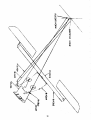
GENERAL
DESCRIPTION
The Taylorcraft. Model B or B12, is a high wing strut braced, two place cabin monoplane
and is available as a land plane or seaplane. The Model B or B12 is obtainable with the
following 65 horsepower engine installations.
Lycoming 0-145-B
Franklin 4AC-176-B2
Continent al A-65-8
SPECIFICATIONS
Gener al (All Mo del s )
Wing Span . . . . . . . . . . . . . . . . . . . . . . . . . . . . . . . . 36 ft.
Height ( Tail Down) • • • .. . . . . • . . . . . . . . . . . . . .. 78 in.
Wing Chord . . . . . . . • . . . . . . . . . . . . . . . . . . • • . . . 63 in.
Length Overall. . . . . . . . . . . . . . . . . . . . . . . . • . . . . 21 ft. 9 in.
1 degree
Dihedral . . . . . . . . . . . . . . . . . . . . . . . . . . . . . . . . .
Wheel s . . . . . . . . . . . . . . . . . . . . . . . . . . . . . . . . . . Shinn
Tires . . . . . . . . . . . . . . . . . . . . . . . . . . . . . . . . .. . 6.00 x 6 2-ply
Tail Wheel. . . . . . . . . . . . . . . . . . . . . . . . . . . . . . . . 6 x 200
FUSELAGE
The fusel age is composed entirely of steel tubing welded into a unit structure. All members
are of S. A.E. No. 1025 or No. 4130 steel. All members are jig cut and in case of replacement they can be furnished ready for welding into the fuselage.
All fuselage tubes are given a protective coating of primer.
Saltwater seaplane fuselages require extra fittings and special cOITosion protection. Fresh
water fuselages have no special corrosion protection. Care should be taken to give replacements for seaplanes the same corrosion protection as the original material. All
saltwater seaplane fuselage tubes are sandblasted, primed, coated with enamel and oiled
on the inside. Information concerning the size and material on any member can be obtained
from the Service Department.
2
WINGS
The wings are a built-up structure having two solid spruce spars braced with steel tubular
drag struts and steel tie rods. The ribs are built up of riveted aluminum sections and
nailed to the spars. The leading edge is formed of sheet aluminum fastened to the ribs
by self-tapping metal screws. The wings are covered with medium airplane fabric which is
sewed to the ribs with 6U commercial gray waxed linen, right twist, rib cord, reinforced by
means of 3/8" herringbone tape and covered with 1-1/2" pinked edge wing tape. Seven or
more coats of high grade airplane nitrate dope provides the cloth with tautness and finish.
AILERONS
The ailerons are also a built-up structure with a spruce spar and with stamped aluminum
ribs. Aluminum leading edge is fastened to the ribs by means of self-tapping metal screws
and nailed to the spar. They are fabric covered and doped. The ailerons are attached to
the wing through steel hinge brackets which are bolted to the rear spar in the wing. The
center hinge bracket carries a horn from which a tubular drag link transmits the motion
to the ail ero n s.
TAIL SURF ACES
The tail surfaces are built up with steel tubing frame work and formed steel ribs. The two
stabilizers and the fin are bolted to the fuselage and wire braced. The two elevators are
bolted at the horn so that they act as a single unit. The fuselage, fin and stabilizers are
equipped with replaceable bronze bushings which should be oiled frequently.
LANDING GEAR
The landing gear is built of tubing forming two separate units and are individually hinged
to the fuselage. Each has replaceable bronze bearings, which should be oiled frequently.
( See diagram)
No part of the landing gear is heat treated. The shock absorbers for each side con.si.3t
of two 9/16" shock cords. There is a rubber bumper installed on the shock truss in the
fuselage which separates the landing gear and the fuselage structure at the point where
the shock cord is attached. A stop cable is also provided at this point to prevent the
shock cord being stretched beyond its elastic limit. Roller bearings are installed in the
wheels. The brakes are cable controlled and of the internal expanding typP. with the lining
on the drums.
Standard planes without brakes are equipped with a spring leaf tail skid. When brakes
are installed, a special spring with a full swivel tail wheel is used in place of the spring
and skid. A steerable tail wheel is also available.
CONTROLS
The control system has dual wheels attached to an H column to control the elevators and
ailerons. The control wheel shafts slide through composition bearings and are connected
to the control column by a universal joint. These wheels may be removed by removing the
bolt connecting the shaft to the universal joint. Always remove the rear hub of the universal joint when removing duals. The right set of rudder pedals may be removed by removing
one bolt from each pedal.
Flexible steel cables are used throughout the control system to transmit motion. All pulleys are mounted on graphite bronze bushings. The trim tab control on the Model B is below
the left seat and is to compensate for slight nose or tail heaviness. To correct for nose
heaviness, the handle is raised and to correct for tail heaviness, the handle is lowered.
The trim tab control on the Model B12 is located on the ceiling, and is turned clockwise to
correct for nose heaviness. See diagram for lubrication and adjustment of trim tab.
3
ENGINE CONTROLS
The engine controls consist of an ignition switch, throttle, a carburetor heater, gas shutoff and primer. There is an altitude adjustment on the Continental carburetor equipped
engines, and available on the Lycoming and Franklin at extra cost. Operation instructions
for the controls are shown on the instrument panel or control knobs. The throttle is located
at the lower center of the instrument panel and is of the push-pull type. The throttle is
pushed forward to open.
FUEL SYSTEM
The fuel system on the B12 consists of a twelve gallon terneplate gas tank located in the
front of the fuselage and a six gallon tank in the right wing. The valve for the wing tank
is located above the corresponding door. The wing tank should be emptied when the main
tank is half empty. Fuel is gravity fed to the carburetor. A small copper screen is placed
in the outlet of the tank. Flexible hose connections are used between the tank, filtrap and
engine. A small copper line is attached to the filtrap inlet to deliver gas through the
primer to the cylinders for starting.
The fuel system on the Model B consists of a twelve gallon tank in the front of the fuselage as standard, and a six gallon auxiliary tank can be installed behind the seat as
extra equipment.
ENGINES
The engines are wet sump motors, having an oil capacity in their crankcase for one gallon
of oil each.
ASSEMBLY OF LANDING VEES
The landing vees are made right and left and the bearings should be oiled or greased just
before assembly. With the fuselage supported at the front end, the vees are then put in
place and assembled with the bolts provided. Tighten the bolts to a snug fit but not tight
enough to resist the motion of the landing gear. Looseness permits excessive wear of the
fittings. Install one shock cord, then the safety cable, followed by the second shock cord
ring for each vee.
To install wheels, place the tapered roller bearings in their proper positions, install
special lock washer and tighten nut sufficient to hold the wheel snugly in place. Be careful not to cause any binding.
4
ASSEMBL Y OF WINGS
The wings are attached to the fuselage through the hinge fittings with the bolts provided.
Hold or block the wing in its approximate position while the wing struts are installed with
the bolts provided. The proper amount of incidence is built into the fuselage fittings and
the dihedral is fixed by the length of the front struts. The rear struts are adjusted at the
factory and must be assembled as tagged. After the plane is out in service, it may change
balance slightly, by developing wing heaviness. To correct this, remove the bolt at the
upper end of the rear wing strut of the opposite of that which is heavy and unscrew the
plug 1/2 turn or more until the balance is corrected. After an airplane has recieved a
major overhaul, it may be advisable to check the complete rigging of the airplane. To
accomplish this, level the plane laterally by attaching a cord from wing tip to wing tip
over the front spar. Place a line level on the center of the string and level the plane by
blocking up the low wheel by a jack or other means. Level the plane longitudinally by
placing a level on the stabilizer close to and parallel to the fuselage. Use a 30" level to
check the incidence at the tip of the wing, (readings to be taken on the first full rib from
the tip). By placing the edge of the level at the forward part of the rear spar along-the rib
mentioned with the level in horizontal position, there will be a gap between the front edge
of the level and the wing of 1-5/16". The plug at the top of the rear strut is used for
adjustment. The tail surfaces are bolted to the fuselage and rigged level and plumb with
the wings with an ordinary level used along the rear tube of the stabilizer and the rear
tube of the fin. The wires to be rigged snug but not too taut. A low bass is satisfactory.
The control cables are provided with turnbuckles for proper adj ustment of the rudder and
elevators.
When rigging the ailerons with the wheel centered, adjust the cables through the zipper in
the back of the cabin so that the trailing edge of the aileron is in line with the trailing
edge of the wing. All cables should be adjusted until they are snug, NOT TIGHT. If the
cables are too tight, there will be too much drag in the aileron control.
STARTING
Before the start of any flight, a complete check should be made of the quantity of gasoline
and oil contained in the tank or motor. Also, it is recommended that the filter bowl be
cleaned frequently because water and dirt will collect there.
When starting, always have a competent person at the controls.
Be sure the gas is turned on and with the switch IN THE OFF POSITION, give the primer
one or two shots, then pull the prop through four or five times. Put the switch in the ON
position, opening the throttle a little and pull the prop through <J1:llckly. If the engine. f~ls
to start, repeat the operation. If the engine loads up, put the sWItch In the OFF pOSitIOn,
open the throttle wide and turn the prop backwards a few times to clear the engine. Then
start in the conventional manner.
CAUTION: Always block the wheels when starting the engine, unless an experienced person is in the cabin controlling the brakes.
5
POINTS TO BE LUBRICATED AT EACH PERIODIC INSPECTION
CONTROLS IN FllSELAGE
In the fuselage the main points to be lubricated are in the control system. The shafts of
the control wheels slide through Bakelite bearings. A small amount of grease on the shafts
will make a smoother working control at thi s point.
The following points on the Control Column should be oiled frequently:
1. The universal joint at the top of the control column.
2. There is al so an oil hole on the top of the control col umn
to 1ubricate the shaft of the universal joint.
3. The sprocket chain links.
4. The bearings at the bottom of the control col umn.
5. All pulley bearings and faces of pulleys.
NOTE: There are two pulleys for the aileron cable at the top front of the cabin and two
more at the rear of the cabin. The front two can be reached through the zipper openings in
the top of the cabin lining and the other two through the zipper opening in the back of
the cabin.
On the right side of the floor just in front of the door are three pulleys carrying the elevator cables and one of the rudder cables. There is one pulley on the left side of the floor
:arrying the other rudder cable. These pulleys should be oiled and checked frequently.
There are also cable guides in the rear of the fuselage that may be seen through the rear
zipper opening that should be checked every 20 hours for frayed cables. There are also
cable guides under the seat which may be inspected by lifting the edge of the seat canvess. Inspection covers at the rear of the fuselage provide access to the elevator control
cable ends and these points should be oiled frequently.
CONTROLS IN WINGS
The aileron control horn which is located in the wing at the center aileron hinge bracket
may be reached by removing the cover plate on the top of the wing. Oil placed in the hole
of the control horn will lubricate the bearing. The ball joints and drag link at this point
should be checked for looseness. Looseness due to wear may be removed by tightening
the ball stud seat in the end of the drag link. The bronze bearings in the aileron hinge
brackets should be oiled frequently. When wear occurs here, new bushings and hinge pins
may be installed.
6
TAIL SURFACES
The hinge joints on all tail surfaces should be oiled frequently. When looseness occurs,
new bushings and hinge pins will correct this condition.
LANDING GEAR
The roller bearings in the landing wheels should be lubricated with graphite grease, being
careful not to get grease on the brake drum or band. Oil the hinge bearings frequently at
the top of the I anding gear between the fittings on the fusel age and I anding gear. On pI anes
equipped with a swivel type tail wheel, oil the swivel bearing and grease the ball bearings
in the hub of the tail wheel.
Note: IT IS IMPORTANT that the bumpers on the fusel age truss under the shock cords
be inspected every 20 hours and repl aced when needed.
PARACHUTES
Provisions for parachutes have been made. By removing the four bolts ( the nuts are riveted in place) on the front edge of the seat and making one-half turn of the leading edge
frame and replacing the bolts, the seat is lowered ample to accommodate parachutes.
WINDSHIELD
The windshield may be changed by simply removing the bolts and clamps around its edges
and replacing it with a new windshield.
GAS TANK
On rare occasions it may be necessary to remove the gas tank. To accomplish this, remove
the control wheels and the front instrument panel which will give access to the tie rods
which support the tank. Next remove the caps from the control column bearings and drop
the column to the floor. Several engine controls and attachments must also be removed.
Remove the forward tie rod nuts next to the firewall and pull the rods. The tank is then
free to be removed down and out through the cabin.
ADJUSTMENT OF BRAKE SHOES ON
MODEL 6C2HB, 6C4HB AND 6CSHB WHEELS
1. Unhook lock springs from adjustment nuts located outside of brake dust shield.
2. Screw in adjustment nuts untill a heavy drag is produced on each shoe. Back out each
nut one-half turn.
3. Apply brake firmly, release and check for drag, If still too much drag on either shoe,
the corresponding adjustment nut must be backed out one-sixth turn at a time, brakes
applied, released and checked for drag untill sufficient clearance is obtained.
4. After a satisfactory adjustment is obtained, the lock springs are engaged in the holes
in the adjustment nut.
7
BRAKE LINING INSTALLATION IN 6C SERIES BRAKE
Can be installed without any special tools
1. Lightly grind ends of lining untill lining is right length for a snug fit in drums.
2. Push lining in drum with gap in lining centered between the rivets which are 1-~"
between centers. Start by hand, then place a board over lining and tap down untill it
is flush with edge of drum.
J. Using drum as jig, drill rivet holes through lining, from outside, with an ordinary
9/64" drill.
4. Remove lining from drum with a claw hammer or other flat ended bar, using care to
raise it evenly all around the circumference.
S. Countersink lining, with countersink drill, to correct size for rivet head (SI16") to
3/32 " depth.
6. Repl ace lining in drum with holes aligned.
7. Place rivets in drum and rivet by setting head of rivet on end of a 5/16" rod held in a
vise and hitting tubular end of rivet with hammer. Care should be taken not to hit the
aluminum drum and not to hammer the rivet more than necessary, as there is danger of
distorting the drum with excessive pounding.
If a special long shank countersink is used, it is not necessary to remove the lining from
the drum in order to countersink it.
Note: As brake lining service shops have a standardized set-up for automobile brake work
and do not care for special jobs, it is recommended that this work be taken to a small
machine shop or garage where there is a drill press or electric drill available.
ELECTRICAL EQUIPMENT
All models of Taylorcraft after serial No. 2529 are wired for lights, and on those that are
not equipped with navigation lights the wires are strung through the wing and taped to the
wing bow at the extreme tip. The wires on the fin are taped to the top edge just ahead of
the trailing edge.
The battery is placed on the floor immediately ahead of the seat, slightly to the left of
the center of the ship and is grounded to the fusel age framework under the seat. The
system is fused in the positive lead where it comes out of the battery box and the fuse
should always be replaced by a fuse of the same capacity as the original installation.
If the ship is equipped with a battery, care must be exercised in charging, as small aircraft batteries should not be charged over 2-112 amperes in excess of any outside draw
such as lights or radio for more than a fifteen minute period.
If the ship is equipped with a generator, charging rate should be held down either by a
brake or adjustment, and if the battery is charged outside, charging should never exceed
2-112 amperes.
If the charging rate is excessive or if one cell is broken down, the battery will boil,
causing acid to leave the battery and perhaps come in contact wi th parts of the ship which
may result in a failure. If the battery is charged out of the airplane, there is not the danger
of damage to the airplane, but the battery is likely to be injured if the charging rate is
excessive.
8
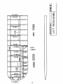
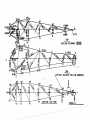
TAYLORCRAFT MODEL B & B12
RIGGING INFORMATION
As the airplane is built entirely in jigs, it requires no rerigging to disassemble and
reassemble the wings. There are only two points where any wing adjustment may be made.
The front wing struts being jig built have no adjustment.
To check the rigging of the wings and tail, stretch a cord across the wings at the front
spar and level the ship with a line level placed over the center of the cabin. Stretch a
second cord across the wings at the rear spar and level with a line level. The rear strut
adjustment is used to accomplish this. The bolt at the point of attachment of the wing
strut with the wing fitting must first be removed. A long screwdriver may be used to move
the adjusting nut as required.
In flight testing, if the airplane flies either wing heavy, the rear strut adjustment may be
used to correct this by washing the opposite wing out, or the heavy wing in.
If the airplane flies nose heavy, both wings may be washed in; or if tail heavy, both wings
may be washed out for correction.
The tail is rigged level and perpendicul ar while the ship is level. An ordinary level used
along the rear tube of the stabilizer and rear tube of the fin will accomplish this. The
wires should be rigged snug but not too taut. A low bass tone is satisfactory.
9
SUPERSEDES A-1379
FOR MODELS LISTED
AM-92
TAYLORCRAFT
DEPARTMENT OF COMMERCE
CIVIL AERONAUTICS ADMINISTRATION
WASHINGTON
BC
BCS
. BC-65
BCS-65
BCI2-65
BCSI2-65
TC 696
September 1, 1942
AIRWORTHINESS MAINTENANCE INSPECTION NOTES
IT IS THE OWNER'S RESPONSIBILITY TO MAINTAIN HIS AIRPLANE SO THAT IT IS ALWAYS
IN AN, AIRWORTHY CONDITION. COMPLIANCE WITH THE NOTES CONTAINED HEREIN IS
CONSIDERED NECESSARY FOR PROPER MAINTENANCE.
This paper should be placed in your airplane of the above model with the airworthiness certificate
or in the log book. The superseded issue (If any) may then be discarded.{In the case of Air Carriers,
the NOTES may be kept at the operator's main base.)
An inspection or revision in accordance with these NOTES must be made at the next periodic
inspection and, in the. case of the "INSPECTION NOTES", at each subsequent periodic inspection
or at the interval stated in the note. "SPECIAL NOTES" need be complied with once only. The
aircraft and engine mechanic making the periodic inspection must make an entry in the airplane (or
engine) log book attesting to his inspection in compliance with these NOTES. (In the case of Air
Carriers, compliance may be noted in the maintenance base records.)
.
The NOTES listed below are based on service experience and are forwarded in an endeaver to
assist in maintaining the airworthiness of your airplane. If you have sold your airplane of the
above noted model, please forward this list to the new owner.
INSPECTION NOTE 1.
(August 7, 1940) (Applies only to airplanes equipped with FreedmanBurnham propeller)
INSPECTION REQUIRED EACH 10 HOURS OF OPERATION.
Inspect Freedman-Burnham propeller models P-20l-72 and P-201-70 for cracks and loose rivets
after each 10 hours of operation in accordance with Airworthiness Maintenance Bulletin No. 31.
(Was SPECIAL NOTE 12 of A-1379)
INSPECTION NOTE 2. (September 4. 1941)
Ascertain that the adjusting nut located at the bottom of the glass bowl of the fuel strainer is
positively safetied in position and also that the cork gasket between the glass bowl and screen
is in serviceable condition. (Was SPECIAL NOTE 22 of A-1379)
5-23530
The follOWing NOTES need be complied with once only.
10
AIRWORTHINESS MAINTENANCE INSPECTION NOTES - Page 2 of 3 pages
AM-92
SPECIAL NOTE 1.
(July 2, 1940; revised December 29, 1941) (Applies to all models listed
except gC12-65 and BCS12-65)
On serial Nos. between 1001 and 1970 inclusive, rest itch the wing ribs using a 6-U linen rib cord
in compliance with Taylorcraft Service gullet in No. 30. (Was SPECIAL NOTE 14 of A-1379)
SPECIAL NOTE 2.
(January 2, 1941) (Applies only to models BC-65 and BCS-65)
Replace coil in aircraft equipped with Bendix-Scintilla SF4L-8, SF4L-9, SF4R-8 or SF4R-9 magnetos
in accordance with Airworthiness Maintenance Bulletin No. 33. (Was SPECIAL NOTE 14'of A-1379)
SPECIAL NOTE 3. (February 5, 1941 )
Federal SC-1 and SC-2 skis used on aircraft certified as skiplanes must incorporate reinforced
channel in accordance with Federal Aircraft Works Service Letter No.2. Federal Aircraft will supply
material and instructions upon request. (Was SPECIAL NOTE 15 of A-1379)
SPECIAL NOTE 4.
(February 5, 1941) (Applies to all models except BC12-65 and BCS12-65)
Inspect weld attaching central column universal to aileron control sprocket shaft. If weld is cracked, rework or replace with a new factory part. (Was SPECIAL NOTE 16 of A-1379)
SPECIAL NOTE 5. (February 5, 1941) (Applies to all models listed except BC12-65 and BCS12-65)
Inspect fuselage members adjacent to aluminum door jamb (or cover) for wear produced by vibratory
action of jamb on structure. Trim jamb to provide a minimum of 1116 clearance at all points. Weld
patch plates to fuselage members if wear appears excessive. (Was SPECIAL NOTE 17 of A-1379)
SPECIAL NOTE 6. (February 5, 1941) (Applies to all models listed except BC12-65 and BCS12.,.65)
Make an entry in the log book outlining the extent of the changes made to insure proper engine
idling operation in compliance with Airworthiness Maintenance Bulletin No.4!. (Was SPECIAL NOTE
18 of A-1379)
SPECIAL NOTE 7.
(July 11, 1941)
Install the stainless steel oil filler cap spring (Continental Part No. 22060) for the following
engines in accordance with Continental Service Bulletin No. 40-3:
Engine Model
Engine Serial No.
Up to No. 1332( Inclusive)
Up to No. 4304 ( Inclusive)
A-50 Series
A-65 Series
And all fuel injection models.
(Was SPECIAL NOTE 19 of A-1379)
11
AIRWORTHINESS MAINTENANCE INSPECTION NOTES - Page 3 of 3 pages
AM-92
SPECIAL NOTE 8. (October 1, 1941 )
Ascertain that the complete engine model designation is shown on the name plate(Le.,A-65-8) in
accordance with Continental Service Bulletin No. 41-12, as the series designation was omitted on
some of the following engines:
A-50
A-65
Up to Serial No. 139819, incl.
Up to Serial No. 1089618, incl.
(Was SPECIAL NOTE 23 of A-1379)
/s/ A. A . Vollnecke
Chief, Aircraft Engineering
Division
KS:MRH
12
Page No.
Bulletin No.
Date
1 of 2
50
10-6-43
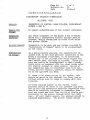
S-E-R-V-I-C-E B-U-L-L-E-T-I-N
TAYLORC&\FT AVIATION CORPORATION
ALLIANCE, OHIO
Subject:
INSPECTlm~
OF CONTROL CABLE PULLEYS, TAYLORCRAFT
MODELS A AND B.
Reason for
To assure ai rworthiness of the subject airplanes.
Airplanes
Affected:
All those airplanes of the Model A and B Series
which still incorporate control pulleys made of
micarta, easily recognized by their black color
and glossy finish.
Accomplishment:
Inspection to be made and any change required by
"Description of Change" below to be accomplished
by the owner.
Description
of Chan~:
As a precautionary measure, the manufacturer requests that at the next periodic inspection on all
Model A and Model B aircraft, it be determined
whether any of the pulleys over which flight control cables pass, are made of micarta. These pulleys can easily be distinguished by their glossy
black color as compared with the usual broVv'Il color
for similar pulleys in later models. Record of
the inspection made in accordance with this bulletin, and the results, thereof, should be recorded in the Aircraft Log Book.
·Chan~:
If there is no black pulley in the system, this
should be noted in the Aircraft Log Book, and no
further action need be taken to comply with this
bulletin.
If black pulleys appear in the system, their
position should be noted in the Aircraft Log Book,
and on this and subsequent periodiC inspection they
should be carefully inspected to determine that
they are sound and free from splits or cracks particularily in the groove through which the cable
runs. If such cracks appear, the pulleys should be
replaced immediately. The groove radius should
13
Page No.
Bulletin No.
Date
2 of 2
50
10 .. 6-43
also be oheoked. This radius should be 5/64". A
oonvenient method of oheoking would be to determine that the shank of a 5/32" drill will bottom
in the groove. If the groove is undersize, the
pulley should be replaoed. Reoord of suoh replaoements should be made in the Airoraft Log Book.
Parts Required
Per Airplane:
Parts required to comply with this bulletin oan
be determined only after inspeotion of the airoraft. Any replacement pulley which may be re ..
quired can be obtained from the manufacturer at
oost plus postage upon notifioation of its
diameter and posit ion in the airplane, the ship
serial no., date of manufaoture , and NC numbers.
S12eoial Tools:
None.
Attention:
If you have sold your airplane, please forward
this bulletin to the new owner.
Haro d ";Jhi te
Service Manager
14
~
tI
I
\)
/'
15
16
B-A 812
;~I
I"'"'""
-
lrI
13-A8o/
l';!
,.
I'
I ~--.:
~!
II
--I.H
11
,j\
I
,
1;
B-A89
Ii
-1
;
I
r
.
~=i!1
co .
I
B-A89
~I
I
F~!
\!J
~
~
~
~
I
~
A-AB60L
8-85
A-A 856
i3-::A809:,
---S'-A-8ii - I
--.-
~t
~1
en
r
&
•
....~.
F=
8-806
~
.....=.:
-
8-85
--
8-85
if-
~1 l r;
h
Il
B-A89
it
A-A859
B8~7
AJE7
"JlL"
L
A -A844
-'
f
J-
~.
•I
'01
\
-.-.:~
_.--:'!'""".
1
I~,..._ B-A89 . t!
...... 1
~
II
q"
!I
t'
-,
~
z:
<r:
,I
17
.. --:
V
~
>
.."
........
1--\.'-0
s:! ~'Ll
_1
~
18
BI2 ·881
8,A SOl
.....
I
--
e-AS,
?2
4:.
<.
~I
8AS1
•...1
~
It
V"
I
II
IlA '01
&&189
VI
"""
8A8S6
I
B·iS
S-AS"
&A800
1
16 -eo,
l~
Bss
I
ooq:~
I
\
.....,
I "8~)
j
BAfJ9
.......
.4"A8G~
'JL
a8~
II'
J/
19
I
I
"""
""
~
~
~
~
~
~
'f
~
~
~
~
....
~
~
~
~hi
~
~
...."
~
~
.~
~
~
'i
,
!
I
~ifdNT
I
SP-4~
I
i
I
~
~
,...;
!
II
~
~
~
.......
~
~
~
~
I
~I't;
'~" ~"
"~
~,...
I
~
~
~
~
~
~
'"
~
tl\
I
CtJ
I
~
mI
I
I
~
~
~
~
1'-
~
~
20
I
!
21
22
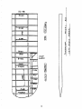
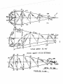
TOP
FUSELAGE ASSEM8LY Uf-AlaJ
10.)
Co»
___
05
1
"
-
.+
SlOE
~AnON NUMBERS ARE fOR 1~£fRINCf
-~-,..,------.,
~~----
14R
--&.
a:; ""':..~
I
S
'\
'7
17l
16L
15L
-
"'?.D
Ij/~
..
tt.
~-.;j..!.tI---~--:...'-.,&
. _~L--.--.
'4L
12L
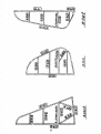
80TTOM - TOP VIEW
.~....---
IJt
lOR
lot cp9
~
::=:f
f\)
~
MODEl B
_
"" 3'1(
~~
-
T
l~~-fff04
1. " \'
l'
"'\
."
11'"
)J
7.£
Tt..')P
- A1,05"
0..
~
...
N
'<]
I~
'lit,,,,
_--
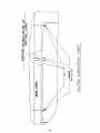
&1510
F//SElAG€ A.!fEi181.
r
8/2." 4/65"'
5T/tT10IV IV/JI)1BERf /-f.i?E !Of( /it7"ERfNCE
c;
A-Ifll
121.
4t.
i'lL.
PI-
11 Q Q G L 8.12:-. . 3//
fblZ'?l!I/_~ 1;,#
2L~"4I_ _
'?€W
.--.
.........-..-
lJ9-iiJal
25
26
/
/
~
,
~
~
't:l
').:
\I)
~
~
~
21
•