1
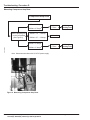
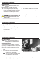
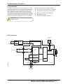
Service Manual DCXXXX, DEXXXX Model Compressor Refrigerators MODELS DC0040(K), DC0051(K) DE0040, DE0051 DE0240T, DE0251T DC0740(X), DE0740(X) DC0751(X), DE0751(X) Please note that the "X" at the end of certain model numbers indicates the equipment color; where "X" can be "B" (black), "S" (stainless steel, or "W" (wrapped door - stainless steel). © 2007 NORCOLD, INC. All rights reserved. Part No. 631842A (08-08-07) Table of Contents Troubleshooting - Procedure A Compressor Doesn't Run with Thermostat "On".............. 3 Troubleshooting - Procedure B Compressor Resistance...................................................4 Measuring the Compressor Resistance........................... 4 Troubleshooting - Procedure C Power Supply Output Voltage..........................................5 Troubleshooting- Procedure D Measuring Compressor Amp Draw..................................6 Troubleshooting - Procedure E Verifying Thermistor Operation........................................7 Troubleshooting - Procedure F Insufficient Cooling...........................................................8 Troubleshooting - Procedures G Refrigerator is Too Cold...................................................8 Troubleshooting - Procedure H Auto Shut-Off Device.......................................................8 Operating the Shut-Off Device..................................... 8 Troubleshooting - Procedure I Proper Ventilation.............................................................9 Wiring Schematic.............................................................9 Troubleshooting - Quick Reference Quick Reference Troubleshooting Steps....................... 10 2 ! DC0040(K), DC0051(K), DE0040, DE0051, DE0240T, DE0251T, DC0740(X), DE0740(X), DC0751(X), DE0751(X) Models WARNING! Perform all tests using a fully charged 12V DC battery. Using other equipment that supplies DC voltage may cause permanent refrigerator component failure. Refrigerator Service Manual Troubleshooting - Procedure A Compressor Doesn't Run with Thermostat "On" DC 0V Is Temperature Control LED on? YES INCORRECT Correct Voltage DC AC AC OPERATION Check AC Power Supply Short Circuit (37 – 45V DC) GOOD (See Figure 5) Change DC Power Supply DC 2V Normal See Procedure B DC 5V DC Power Supply Failure Change DC Power Supply Compressor Runs YES OK Reverse Polarity Check Both Check DC & Check Operation DC Fuses BLOWN Polarity INCORRECT (Red + / Black -) OK OK Replace 10A Fuse (See Figure 2) Compressor Runs YES Replace 10A Fuse (See Figure 2) ART01945 DC 0V DC 12 to 32V OK NO NO AC OPERATION Normal Compressor Runs YES OK DC OPERATION Measure Terminal Voltage of Temperature Control Between TP2 & TP3. (See Figure 1) Change AC Power Supply NO CORRECT Power Source Change DC Power Supply BAD Measure Terminal Voltage Of Temperature Control Between TP1 & TP2. (See Figure 1) NO Check Supply Voltage (10.5 – 32V DC) (85 – 132V AC) Short Circuit DC OPERATION Thermostat “ON” Compressor Does Not Run See Procedure B Check AC Power Supply (37 – 45V DC) GOOD (See Figure 5) BAD DC Power Supply Failure Change DC Power Supply DC Power Supply Failure Change DC Power Supply Change AC Power Supply Note: Measurements taken with 12.8V DC or 120V AC power supply. Black Red ART01946 ART01944 Brown Figure 1. Temperature Control Figure 2. Fuse Locations NOTE: If 10 Amp fuse is blown, check the vehicle's wiring. Refrigerator Service Manual DC0040(K), DC0051(K), DE0040, DE0051, DE0240T, DE0251T, DC0740(X), DE0740(X), DC0751(X), DE0751(X) Models 3 Troubleshooting - Procedure B Compressor Resistance Compressor Resistance ART01947 Measure Compressor Resistance. See Figure 3. 0 Internal Compressor Failure Change Cooling Unit 1.4 – 3.5 Normal See Procedure C Note: Perform procedure at room temperature. Measuring the Compressor Resistance 1. Turn the temperature control to the "Off" position. 2. Remove the black wire to the compressor. B A ART01958 3. Measure the resistance of the compressor between point A and point B. Refer to Figure 3. Figure 3. Measuring Compressor Resistance 4 DC0040(K), DC0051(K), DE0040, DE0051, DE0240T, DE0251T, DC0740(X), DE0740(X), DC0751(X), DE0751(X) Models Refrigerator Service Manual Troubleshooting - Procedure C Power Supply Output Voltage Power Supply Output Voltage DC OPERATION Less than 15V AC Check AC Power Supply. (37 - 45V DC) (See Figure 5) AC OPERATION GOOD DC Power Supply Failure Change DC Power Supply DC Power Supply Failure Change DC Power Supply BAD Measure Voltage Between A & B At the Compressor (See Figure 4) Go to Procedure E 0V AC GOOD THERMISTOR Power Source Change DC Power Supply DC DC Power Supply Failure Change DC Power Supply DC Power Supply Failure Change DC Power Supply AC FAULTY THERMISTOR Check AC Power Supply. (37 - 45V DC) (See Figure 5) Change Thermistor GOOD BAD ART01948 15 - 25V AC Change DC Power Supply Normal See Procedure D Note: Measurements taken with 12.8V DC or 120V AC power supply. A ART01950 ART01949 B Figure 4. Measuring Power Supply Output Voltage Refrigerator Service Manual Figure 5. Measuring AC Power Supply Output DC0040(K), DC0051(K), DE0040, DE0051, DE0240T, DE0251T, DC0740(X), DE0740(X), DC0751(X), DE0751(X) Models 5 Troubleshooting- Procedure D Measuring Compressor Amp Draw Compressor Amp Draw 40Watt < 1.6Amps 60Watt < 2.7Amps Measure Amperage at ‘A’ on the Compressor (See Figure 6) 40Watt = 1.6 – 2.0Amps 60Watt = 2.7 – 3.3Amps 40Watt > 2.0Amps ART01952 60Watt > 3.3Amps Compressor Failure Change Cooling Unit Normal Compressor Failure Change Cooling Unit Note: Measurements taken with 12.8V DC power supply. ART01953 A Figure 6. Measuring Compressor Amp Draw 6 DC0040(K), DC0051(K), DE0040, DE0051, DE0240T, DE0251T, DC0740(X), DE0740(X), DC0751(X), DE0751(X) Models Refrigerator Service Manual Troubleshooting - Procedure E Verifying Thermistor Operation To measure the resistance of the evaporator thermistor, complete the following procedure. 1. Turn the temperature control to the "Off" position. 2. Disconnect the 3-pole connector. Refer to Figure 7. 3. Measure the resistance across the two pins. Refer to Figure 8. 4. Check the evaporator thermistor by measuring the temperature and resistance of the thermistor. NOTE: In general, 1.6K - 29KΩ = good thermistor. ∞Ω = defective thermistor. An open thermistor will stop normal compressor operation. Replace the defective thermistor. ART01955 Refer to Table 1 for a listing of acceptable resistance ranges. ART01954 Figure 8. Measure Resistance Across Pins Figure 7. Evaporator Thermistor Connection (Inside Power Supply) Evaporator Thermistor Resistance Thermistor Temperature (°F) (°C) Resistance Allowable Resistance Range 0 -18 9.7 KΩ 8.7 - 10.7 KΩ 10 -12 7.8 KΩ 7.0 - 8.6 KΩ 20 -7 6.4 KΩ 5.7 - 7.0 KΩ 30 -1 5.3 KΩ 4.8 - 5.7 KΩ 40 4 4.5 KΩ 4.0 - 4.9 KΩ 50 10 3.6 KΩ 3.2 - 4.0 KΩ 60 16 2.8 KΩ 2.5 - 3.1 KΩ 70 21 2.1 KΩ 1.9 - 2.3 KΩ 80 27 1.9 KΩ 1.7 - 2.0 KΩ 90 32 1.8 KΩ 1.6 - 1.9 KΩ Table 1. Evaporator Thermistor Resistance Refrigerator Service Manual DC0040(K), DC0051(K), DE0040, DE0051, DE0240T, DE0251T, DC0740(X), DE0740(X), DC0751(X), DE0751(X) Models 7 Troubleshooting - Procedure F Insufficient Cooling NOTE: Check input voltage before proceeding. Refer to Procedure A. If the compressor runs continuously, do the following: ■■ Check the voltage across the fan leads. There will be a slight voltage reading even if the fan isn't operational. The fan will only operate when the compressor is running, and the ambient temperature is sufficient to engage the fan. The operational voltage of the fan is between 17 and 22VDC. If this is present at the leads and the fan is not running, replace the fan. ! CAUTION: When servicing the fan, do not short the wires. Shorting the wires will damage the power supply. ■■ Make sure that the ventilation vents are not blocked. Refer to Procedure I. ■■ Make sure that the auto shut-off device is operational. Refer to Procedure H. ■■ If the reason for insufficient cooling is not found, start with Procedure B. Replace the cooling unit if: ■■ The compressor is hot to the touch and not vibrating. ■■ The compressor vibrates but there is no cooling. Troubleshooting - Procedure G Refrigerator is Too Cold If the refrigerator is too cold, do the following: ■■ Adjust the temperature control to a lower setting. Number 1 is the warmest setting; number 5 is the coldest. ■■ Make sure that the thermistor is securely mounted to the evaporator plate. ■■ If you cannot determine a cause, refer to Procedure E. Troubleshooting - Procedure H Auto Shut-Off Device NOTE: Only the 12/24V DC and DE/Truck models are equipped with the auto shut-off device within the power supply. Operating the Shut-Off Device 1. Turn the temperature control counterclockwise to the "Off" position. 2. Turn the temperature control to the desired setting. ART01956 To protect the cooling unit from overheating, the refrigerator will automatically shut-off when the ambient air temperature is approximately 110°F (43°C). If shut-off occurs, the refrigerator will sound an intermittent alarm tone. To stop the alarm, the refrigerator must be restarted using the following procedure: NOTE: The refrigerator will not restart until the ambient conditions allow for normal operation. Figure 9. High Temperature Shut-off Device NOTE: To test the shut-off device's functionality, heat the device with a heat gun. Refer to Figure 9. 8 DC0040(K), DC0051(K), DE0040, DE0051, DE0240T, DE0251T, DC0740(X), DE0740(X), DC0751(X), DE0751(X) Models Refrigerator Service Manual Troubleshooting - Procedure I Proper Ventilation Reducing the vent area can cause the following: Ventilation is necessary for the correct operation of the refrigerator. Good ventilation also increases the life of the refrigerator's cooling system. The current models are equipped with built-in ventilation systems that draw cooler air through the lower intake vent. This air is then circulated over the cooling unit to remove excess heat from the cooling system. The heated air is then rejected through the upper vent. If this airflow is blocked or decreased, the refrigerator will not cool correctly. ! ■■ Shortened life of the refrigeration-cooling unit. ■■ Poor cooling performance of the refrigerator. ■■ Continuous operation of the refrigerator. ■■ Fast battery discharge. ■■ Voiding the refrigerator warranty. CAUTION: Do not block the vents by closet or cabinet doors. Wiring Schematic FAN MOTOR 24V DC ORANGE ~ WHITE AC 85~132V AC IN(L) B3P-VH AC IN(N) AC/DC converter + DC OUT + RED - DC OUT - BLACK AC/DC PART CN1 B2P-VH RED BLACK XHP-2 DC INPUT B2B-XH-A BATTERY IN + RED DC 12~32V DC/DC converter FUSE BLACK BATTERY IN - DC 39V FOR 40W DC 41V FOR 60W + INVERTER FUSE CONDENSOR COUPLING SK515-N CN2 B3P-VH VHR-3N INPUT HIGH BATTERY VOLTAGE MONITOR (OPTIONAL) PROTECTOR HIGH TEMPERATURE ELECTRONIC PROTECTER THERMOSTAT BUZZER (OPTIONAL) ART01957 LOW TEMPERATURE PROTECTER CN4 B2B-EH EHR-2 BLACK AMBIENT THERMISTOR AMBIENT ELECTRONIC CURRENT THERMISTOR PROTECTOR DC/AC PART BLACK EVAPORATOR THERMISTOR Refrigerator Service Manual DC0040(K), DC0051(K), DE0040, DE0051, DE0240T, DE0251T, DC0740(X), DE0740(X), DC0751(X), DE0751(X) Models 9 Troubleshooting - Quick Reference Quick Reference Troubleshooting Steps 1. Check for supply voltage at the rear of the refrigerator. 2. Turn the temperature control to the "On" position. The operating voltage should be between 10.5V and 32V DC. There will be some variation in these readings depending on the supply voltage. B A If voltage is not within range, refer to Procedure C. 4. With the refrigerator power on, take an Ohm reading (1.4 - 3.5Ω) at the compressor between points A and B. Refer to Figure 11. If the Ohm reading is not within range, refer to Procedure B. ART01958 3. Check the compressor voltage between points A and B. Voltage should be between 15V - 25V AC. Refer to Figure 10. Figure 11. Taking an Ohm Reading 5. With the refrigerator power off, and the lead removed from point "A", take an Amp reading (1.6 - 3.3 Amps) at the black wire with the rubber boot. Refer to Figure 12. If amperage is not within range, refer to Procedure D. A A Figure 10. Checking Compressor Voltage 10 DC0040(K), DC0051(K), DE0040, DE0051, DE0240T, DE0251T, DC0740(X), DE0740(X), DC0751(X), DE0751(X) Models ART01953 ART01949 B Figure 12. Measuring the Amp Draw Refrigerator Service Manual This Page Intentionally Left Blank. NORCOLD, Inc. P. O. Box 4248 Sidney, OH 45365 DCXXXX, DEXXXX Compressor Refrigerator Service Manual NORCOLD, Inc. Customer Support Dept. Telephone: 800-543-1219 Fax: 937-497-3183 www.norcold.com Part No 631842A (08-08-07)