1
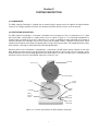
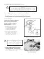
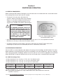
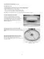
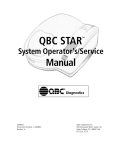
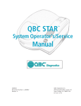
® Diagnostics Innovative Solutions for a Healthier World Q BC Capillary Centrifuge Operator’s/Service Manual ® ® Diagnostics Innovative Solutions for a Healthier World Q BC Capillary Centrifuge Operator’s/Service Manual ® QBC, QBC Diagnostics, ParaLens, and ParaLens Advance are trademarks of QBC Diagnostics, Inc. Copyright © 2006 by QBC Diagnostics, Inc., and Vacutainer is a trademark of Becton, Dickinson, & Company. 4740-020-004 Rev G Table of Contents Section 1 INTRODUCTION....................................................................................................................................1 1.1 INTENDED USE.............................................................................................................................................1 1.2 SUMMARY AND EXPLANATION...................................................................................................................1 1.2.1 QBC Centrifugal Hematology Tests.......................................................................................................1 1.2.2 QBC Malaria Test...................................................................................................................................2 1.3 PRINCIPLES OF THE PROCEDURES...........................................................................................................2 1.3.1 QBC Centrifugal Hematology Tests.......................................................................................................2 1.3.2 QBC Malaria Test...................................................................................................................................3 1.4 WARNINGS AND PRECAUTIONS.................................................................................................................3 1.5 SYMBOL DEFINITIONS.................................................................................................................................3 Section 2 SYSTEM DESCRIPTION........................................................................................................................4 2.1 COMPONENTS..............................................................................................................................................4 2.2 CENTRIFUGE DESCRIPTION........................................................................................................................4 2.3 POWER PACK...............................................................................................................................................5 2.4 SPECIFICATIONS..........................................................................................................................................5 2.4.1 QBC Capillary Centrifuge (part no. 425740)...........................................................................................5 2.4.2 QBC Power Pack (part no. 421763).......................................................................................................5 Section 3 INSTALLATION AND SET-UP...............................................................................................................6 3.1 PACKAGING AND PARTS.............................................................................................................................6 3.2 INSTALLATION AND SERVICE......................................................................................................................6 3.3 CONNECTING POWER UNIT........................................................................................................................7 3.4 PLACEMENT AND OPERATING ENVIRONMENT.........................................................................................7 3.5 ROTOR ASSEMBLY......................................................................................................................................8 Section 4 CENTRIFUGE OPERATION...................................................................................................................9 4.1 GENERAL PROCEDURES.............................................................................................................................9 4.2 BETWEEN-SPIN TIME DELAY.......................................................................................................................9 4.2.1 QBC Centrifugal Hematology Tubes......................................................................................................9 4.2.2 QBC Malaria Test.................................................................................................................................10 4.3 TUBE LOADING AND BALANCING.............................................................................................................10 4.4 EMERGENCY UNLATCHING OF LID..........................................................................................................11 4.5 SPEED/POWER LED MONITORS...............................................................................................................11 4.6 PRECAUTIONS AND HAZARDS.................................................................................................................12 Section 5 SPECIMEN COLLECTION...................................................................................................................13 5.1 GENERAL.....................................................................................................................................................13 5.2 HANDLING PRECAUTIONS........................................................................................................................13 5.3 SPECIMENS FOR QBC HEMATOLOGY TESTS.........................................................................................13 5.4 SPECIMENS FOR QBC MALARIA TEST.....................................................................................................14 ii Table of Contents (continued) Section 6 CENTRIFUGATION PROCEDURES....................................................................................................15 6.1 MATERIALS PROVIDED..............................................................................................................................15 6.2 MATERIALS REQUIRED BUT NOT PROVIDED..........................................................................................15 6.2.1 QBC Centrifugal Hematology Tests.....................................................................................................15 6.2.2 QBC Malaria Test.................................................................................................................................15 6.3 TEMPERATURE REQUIREMENTS..............................................................................................................15 6.4 CENTRIFUGATION INSTRUCTIONS...........................................................................................................16 6.4.1 Affixing Identification Labels................................................................................................................16 6.4.2 Loading and Balancing Rotor...............................................................................................................16 6.4.3 Centrifugation Procedures...................................................................................................................16 6.4.4 Testing Time.........................................................................................................................................17 Section 7 LIMITATIONS OF PROCEDURES.......................................................................................................18 7.1 QBC CENTRIFUGAL HEMATOLOGY TESTS..............................................................................................18 7.2 QBC MALARIA TEST...................................................................................................................................18 Section 8 CALIBRATION CHECKS.....................................................................................................................19 8.1 CHECKING ROTOR SPEED........................................................................................................................19 8.2 CHECKING TIMER ACCURACY..................................................................................................................19 Section 9 MAINTENANCE AND SERVICE..........................................................................................................20 9.1 GENERAL CLEANING.................................................................................................................................20 9.2 ROTOR MAINTENANCE..............................................................................................................................20 9.2.1 Periodic Inspection...............................................................................................................................20 9.2.2 Rotor Cleaning Procedures..................................................................................................................21 9.3 RELEASING LID LATCH..............................................................................................................................22 9.4 TROUBLESHOOTING..................................................................................................................................23 9.5 PARTS LIST.................................................................................................................................................25 WARRANTY...........................................................................................................................................................26 iii iv Section 1 INTRODUCTION 1.1 INTENDED USE The QBC Capillary Centrifuge (Figure 1-1) is an ultra-compact instrument, designed to spin down blood specimens for QBC centrifugal hematology tests or the QBC Malaria Test. Figure 1-1. QBC Capillary Centrifuge, Model 425740. 1.2 SUMMARY AND EXPLANATION 1.2.1 QBC Centrifugal Hematology Tests QBC centrifugal hematology tests are based on a high-precision glass capillary tube containing an equally precise plastic float. When the tube is filled with blood, sealed, and centrifuged at high speed for five minutes, the float is buoyed by the packed red cells, automatically positioning the float within the buffy coat layer, between the packed red cells and the plasma. QBC tubes for hematology are produced in a standard design (which contain an unassembled float and tube closure). Under centrifugation, blood cells in the buffy coat layer separate according to their densities, forming visibly discrete bands as shown in Figure 1-2. Platelets constitute the topmost band, lymphocytes and monocytes the center band, while granulocytes, the heaviest band, form immediately above the packed red cells. PLASMA PLATELET LAYER WHITE CELLS (LYMPHOCYTES/ MONOCYTES/ GRANULOCYTES) RED CELLS FLOAT RED CELLS AROUND FLOAT STOPPER Figure 1-2. Cell layers in Centrifuged QBC Hematology Tube. 1 1.2.1 QBC Centrifugal Hematology Tests (continued) Coated reagents in the QBC blood tube enhance the visual separation between cell layers and provide differential staining so that tubes can be read by non-automatic and automatic QBC analyzers. 1.2.2 QBC Malaria Test The centrifugal test for detecting malaria parasites is based on a high precision glass capillary tube containing an equally precise plastic float. When the blood-filled tube is centrifuged at high speed for five minutes, the float is buoyed by the packed red cells, automatically positioning the float within the buffy coat layer, between the packed red cells and the plasma. During centrifugation, blood cells in the buffy coat separate according to their densities, forming visibly discrete bands (Figure 1-3). Platelets constitute the topmost layer, lymphocytes and monocytes the middle layer, and granulocytes, being the heaviest of the buffy coat cells, concentrate immediately above the packed red cells. Reagents coated in the QBC Malaria Test tube promote separation and metachromatic staining of these cells. GRANULOCYTE LAYER LYMPHOCYTE/MONOCYTE LAYER LIGHT RED CELLS (AROUND FLOAT) PLATELET LAYER DARK RED CELLS PRIMARY MALARIA DETECTION ZONE PLASMA FLOAT SECONDARY MALARIA DETECTION ZONE White Label Lines Blue Fill Lines (55-65 µL) Figure 1-3. Differentiated Cell Layers in Spun QBC Malaria Test. Examination of the centrifuged blood under a fluorescence microscope, or a light microscope with the QBC ParaLens AdvanceTM LED fluorescence microscope attachment, readily permits the detection of malaria in the infected cells and plasma. Direct malaria detection by the QBC Test method is therefore more rapid than conventional blood-film microscopy. 1.3 PRINCIPLES OF THE PROCEDURES 1.3.1 QBC Centrifugal Hematology Tests The QBC Capillary Centrifuge is designed to spin up to 20 QBC blood tubes at the force-time requirements needed to produce optimally packed cell layers for cell counting and analyses. QBC blood tubes are 75 mm glass tubes, internally coated with potassium oxalate, acridine orange, anticoagulants, and an agglutinating agent. The tubes are sealed with a plastic closure or rubber stopper and contain a precision-molded float within the bloodfilled tube. Rotor speed and timing of the centrifuge are computer controlled for maximum consistency in the formation of packed cell layers in spun QBC tubes. 2 1.3.1 QBC Centrifugal Hematology Tests (continued) For technical assistance with QBC hematology tests contact: +1-866-265-1486 (toll free); +1-814-692-7661 QBC Diagnostics Inc. 168 Bradford Drive, Port Matilda, PA 16870 U.S.A. 1.3.2 QBC Malaria Test The QBC Capillary Centrifuge is designed to spin up to 20 QBC Malaria Test tubes at the force-time requirements needed to cause the infected cells to concentrate in a narrow area of the tube for easy identification. The QBC Malaria Test is a 75 mm glass capillary tube, internally coated with potassium oxalate, acridine orange stain and anticoagulants. Expansion of the separated cell layers is achieved with a plastic float, which is inserted into the tube prior to centrifugation. Rotor speed and timing of the centrifuge are computer controlled for consistent performance. For malaria detection in the centrifuged sample, the tube is examined under a fluorescence microscope or the ParaLens Advance, in the region between the light red blood cells and granulocytes and lymphocytes/monocytes, where the parasites are most abundant. For technical assistance with the QBC Malaria Test contact: +1-866-265-1486 (toll free); +1-814-692-7661 QBC Diagnostics Inc. 168 Bradford Drive, Port Matilda, PA 16870 U.S.A. 1.4 WARNINGS AND PRECAUTIONS Always observe good laboratory procedures when handling patient specimens. WARNING BLOOD SPECIMENS USED FOR THESE PROCEDURES MAY CONTAIN THE HEPATITIS B AND C VIRUS, HUMAN IMMUNODEFICIENCY VIRUS (HIV), OR OTHER INFECTIOUS DISEASES. HANDLE BLOOD AS A POTENTIAL BIOHAZARD CAPABLE OF TRANSMITTING INFECTION. ALWAYS WEAR GLOVES AND OTHER APPROPRIATE BLOOD BARRIER PROTECTION WHEN COLLECTING AND PREPARING BLOOD. WARNING QBC TUBES ARE MADE OF GLASS. EXERCISE CARE WHEN HANDLING AND PREPARING TUBES TO PREVENT BREAKAGE AND POSSIBLE INJURY. Consult Section 4.6 of this manual for detailed safety precautions. IMPORTANT: The coating ingredients in QBC tubes for hematology differ from those in the QBC Malaria Test tubes. Accordingly, do not interchange QBC hematology tubes with QBC Malaria Test tubes, since erroneous test results will be obtained. 1.5 SYMBOL DEFINITIONS Direct Current (non-alternating) Not for use in the presence of flammable gases. Attention! Read the attached note! 3 Section 2 SYSTEM DESCRIPTION 2.1 COMPONENTS The QBC Capillary Centrifuge is shipped with an external plug-in power pack that supplies the required direct current (D.C.) voltage to power the motor, circuit board and other internal systems of the instrument. 2.2 CENTRIFUGE DESCRIPTION The QBC Capillary Centrifuge is a compact, low-profile unit measuring less than 13 centimeters (5.1 in.) high with cover down, and housed in a sturdy plastic case. As shown in Figure 2-1, the centrifuge incorporates a 20-place rotor, mounted to the shaft of a brushless D.C. motor. In addition to shock-mounting of the motor to minimize vibration, the centrifuge rests on four suction feet for added stability. A protective metal cover, which threads onto the motor shaft, keeps the spinning tubes snugly in place on the rotor. The hinged top lid with safety latch provides a housing or shield around the rotor during operation. Electrical power to the centrifuge is controlled by a momentary ON/OFF power button located on the front deck. Before the motor will start, the top lid must be closed and latched. Once a spin cycle has started, a safety interlock prevents the lid from being opened until the rotor brakes to a stop. The spin cycle is controlled by an electronic timer on the main circuit board. Spin time is fixed at 5 min. Lid Latch Rotor Cover Lid Assembly Power Input Cable Rotor ON/OFF Button Head Nut Safety Interlock Switch Green Speed LED Yellow Power LED Figure 2-1. Features and Controls of QBC Capillary Centrifuge. 4 2.2 CENTRIFUGE DESCRIPTION (Continued) A green light emitting diode (LED) for “SPEED” and a yellow LED for “POWER” adjacent to the “ON/OFF” button provide visual indicators of power circuit status. Condition of each LED (On, Off, or Flashing) based on the status of power, lid latching, rotor speed, etc., is described in Sections 4.5 and 9.5. 2.3 POWER PACK The Power Pack for the QBC Capillary Centrifuge is a table-top, 130 watt, switched-mode power supply, with a universal input range (100-240 VAC) and a 48 VDC output. 2.4 SPECIFICATIONS 2.4.1 QBC Capillary Centrifuge ¨ ¨ ¨ ¨ ¨ ¨ ¨ ¨ ¨ ¨ ¨ ¨ ¨ ¨ ¨ Rotor Capacity: 1 to 20 QBC tubes. Rotor Speed: 12,000 rpm ± 80 rpm. Nominal Relative Centrifugal Force (RCF): 14,387 x g. Timer: Electronic, 300 s spin, 15-20 s deceleration. Electro-Mechanical Safety Interlock: Lid must be closed and latched before motor can be energized. Lid remains locked until rotor stops. Operating Temperatures: • For QBC Hematology: 20 to 32 ºC (68 to 90 ºF).* • For Parasite Detection: 16 to 37 ºC (60 to 99 ºF).* Functional Range: • Centrifuge Operation: 2 to 40 ºC (36 to 104 ºF).* Operating Relative Humidity: 0% to 80% for temperatures between +2 and 31 ºC, derating linearly to 50% between 31 and 40 ºC. Non-Operating Storage Temperature Limits: -26 to 66 ºC (-15 to 150 ºF) Weight (with rotor and cover installed): 2.8 kg (6.2 lbs). Dimensions (with lid closed) 23.5 cm W x 29.8 cm D x 12.7 cm H. (9.25 in. W x 11.75 in. D x 5 in. H.) Transient Overvoltage Category I. Indoor or under-cover use only. Pollution Degree II. Electrical: 48 VDC ± 3 VDC, 2.7 ADC Maximum, Steady State. 2.4.2 QBC Power Pack The power supply accompanying or sold with the QBC Capillary Centrifuge is recognized under UL 60950-1; CSA C22.2 No. 60950-1; 2006/95/EC Low Voltage Directive and 2004/108/EC EMC Directive. ¨ ¨ ¨ ¨ Input: 100-240 VAC, 47-63 Hz Output: 48 ± 3 VDC, 2.7 amp DC Output Cord AC Line Cord (unassembled): • Standard Cord: 2.3 m (7.5 ft) • Continental European Cord: 2.5 m (8.2 ft) *For temperature specifications: consult the package insert of the disposables in use in your laboratory. 5 Section 3 INSTALLATION AND SET-UP 3.1 PACKAGING AND PARTS The QBC Capillary Centrifuge and Power Pack are shipped in a single container, together with the following parts, test accessories and instructions (Figure 3-1): • Rotor Cover Assembly • Head Nut Wrench • Two Power Pack Line Cords (see below) • Rotor Removal Wire • Operating Instructions (this Manual) Note: For use of the centrifuge in Continental Europe, an alternate line cord is provided with the Power Pack. Select the appropriate line cord and discard the unused cord. 3.2 INSTALLATION AND SERVICE For first-time users of the QBC System, a representative of QBC Diagnostics Inc. or your local QBC System distributor will normally install the required equipment; the installer will also train operating personnel in proper use of the equipment. If necessary, contact your nearest QBC Diagnostics Inc. office to arrange for installation service. Figure 3-1. QBC Capillary Centrifuge, Showing Parts and Accessories. (Note: Centrifuge is supplied with rotor installed.) 6 3.3 CONNECTING POWER UNIT Be sure the Power Pack is not plugged in. Connect the power pack output cable plug to the power input cable on the right side of the centrifuge (Figure 3-2). Using the appropriate line cord (Figure 3-3), connect the female plug to the receptacle in the side of the Power Pack and the male plug to a grounded AC power receptacle. Figure 3-2. Connecting Power Pack Output Cable to Centrifuge Power Input Cable Figure 3-3. Power Pack and AC Line Cord CAUTION To avoid electrical hazards and equipment damage, connect the power cord only to grounded receptacles delivering the voltage and frequency specified on the data plate of the power supply, with a switch or other means of circuit disconnection located outside the clearance envelope defined in Section 3.4 of this manual. When only a 2-wire receptacle and/or an unswitched line is available, have the receptacle and/or the supply line modified by a qualified service technician, in accordance with applicable electrical codes, to conform to this note. 3.4 PLACEMENT AND OPERATING EQUIPMENT Place the centrifuge on a smooth, level working surface in a location where it will not be exposed to direct sunlight. Centrifugations in direct sunlight can elevate the rotor compartment temperature and may adversely affect the formation of readable cell layers in QBC blood tubes. For stability, be sure the unit rests on its suction feet. Mark an envelope 300 mm (~12 inches) wider than the body of the centrifuge around the area in which the centrifuge is to be used. Keep all personnel and hazardous materials outside this envelope when the centrifuge is operating. 7 3.4 PLACEMENT AND OPERATING EQUIPMENT (continued) WARNING IF THIS EQUIPMENT IS USED IN A MANNER INCONSISTENT WITH THE MANUFACTURER’S SPECIFICATIONS, THE PROTECTION AGAINST HAZARDS THIS DEVICE PROVIDES MAY BE IMPAIRED. Be sure to keep the operating area within the temperatures listed below. • For QBC Centrifugal Hematology tests: operating temperature should be maintained at 20 to 32 ºC (68 to 90 ºF) to assure proper cell layering in QBC blood tubes. • For QBC Malaria Test: operating temperature should be maintained at 16 to 37 ºC (60 to 99 ºF) to assure the concentration of parasitic organisms. 3.5 ROTOR ASSEMBLY Rotor The QBC Capillary Centrifuge is shipped with the rotor assembly completely installed. If the rotor is removed, for example for cleaning (see Section 9.2), it can be reinstalled as follows: Hub Slots Motor Shaft a) Position the rotor so that the slots on the underside of the rotor hub are aligned with the drive pin in the motor shaft (Figure 3-4). b) Press the rotor down until the drive pin is seated in the hub slots and 3-5 threads of the shaft protrude above the hub, about 6 mm (¼”). Drive Pin 3-5 protruding shaft threads Rotor Figure 3-4. Installing Rotor Assembly. CAUTION TO PREVENT DAMAGE TO ROTOR COVER AND CENTRIFUGE LID, BE SURE ROTOR IS CORRECTLY SEATED ON DRIVE PIN. c) Thread the head nut onto the shaft finger-tight, by turning it clockwise. Tighten with a light torque using the head nut wrench supplied with the centrifuge (Figure 3-5). DO NOT OVERTIGHTEN. Turn nut 1-2 tube positions to tighten. Figure 3-5. Tightening Rotor with Head Nut Wrench 8 Section 4 CENTRIFUGE OPERATION 4.1 GENERAL PROCEDURES Before starting the QBC Capillary Centrifuge, be sure the rotor cover is installed and the lid is closed and latched. The centrifuge will not start unless the lid is latched. • To start the 5-min spin, press and release the ”ON/OFF” button on the front deck of the centrifuge (Figure 4-1). The rotor will begin accelerating until it stabilizes at the design speed. See Section 4.5 for sequencing of ‘POWER’ and ‘SPEED’ indicator lights. CAUTION TO PREVENT PERSONAL INJURY OR DAMAGE, NEVER LEAN ON, PICK UP, OR TILT THE CENTRIFUGE WHILE IT IS OPERATING. NEVER REMAIN WITHIN THE CLEARANCE ENVELOPE DEFINED IN SECTION 3.4 OF THIS MANUAL LONGER THAN NECESSARY FOR OPERATIONAL REASONS. Figure 4-1. Detail of ON/OFF Button and POWER/SPEED LED’s. • Spin time is fixed at 5 min and is not adjustable. After 5-min spin, 15-20 s are required for the rotor to decelerate to a full stop, at which time the lid latch unlocks. • To stop the centrifuge any time during a spin, press and release the “ON/OFF” button. Note: After completing any spin cycle (full or interrupted) the timer is automatically reset to zero. 4.2 BETWEEN-SPIN TIME DELAY Since the QBC test method depends upon proper cell layering in the hematology and QBC Malaria Test tubes, blood sampled must be protected from excessive heat buildup in the rotor compartment, which may adversely affect cell layer formation. Accordingly, between successive spins be sure to wait the appropriate time specified below. IMPORTANT: During each between-spin rest, be sure the rotor cover is removed and the rotor empty. 4.2.1 QBC Hematology Tubes • If room temperature is 24 ºC or less (≤ 75 ºF), wait 1 min between spins. • If room temperature is 25 - 28ºC (75 - 82 ºF), wait 3 min between spins. • If room temperature is 29 - 30ºC (84 - 86 ºF), refer to the table below. Between 1st & 2nd Spins Between 2nd & 3rd Spins Between 3rd & 4th Spins Between 4th & 5th Spins Above 5 Spins 3 min. 6 min. 9 min. 12 min. 15 min. • If room temperature is 31 - 32 ºC (88 - 90 ºF), wait 30 min between spins. Note: During QBC Hematology tests using standard QBC tubes, room temperature should not exceed 32 ºC (90 ºF).* *Important: For room temperature specifications: consult the package insert of the disposables in use in your laboratory. 9 4.2 BETWEEN-SPIN TIME DELAY (continued) 4.2.2 QBC Malaria Test • • • If room temperature is less than 33 ºC (< 91 ºF), wait 1 min between spins. If room temperature is 33 - 35 ºC (91 - 95 ºF), wait 3 min between spins. If room temperature is 36 - 37 ºC (97 - 99 ºF): - With 1 to 5 consecutive spins, wait 6 min between spins. - With consecutive spins above 5, wait 9 min between spins. Note: During use of QBC Malaria Test, room temperature should not exceed 37 ºC (99 ºF). 4.3 TUBE LOADING AND BALANCING The top lid is spring-loaded and is automatically released when the Power switch of the centrifuge is off, provided the Power Pack is on and connected to the centrifuge. When a spin cycle is completed, the latch releases after a momentary delay and the lid pops up (Figure 4-2). Figure 4-2. Spring-Loaded Lid Latch Mechanism Place tubes on the rotor in a balanced array, with the tube closures against the outer rim of the rotor. To maintain balance, insert the tubes consecutively, starting at slot #1. When spinning an odd number of tubes (e.g., three), BE SURE TO BALANCE THE ROTOR BY PLACING AN UNFILLED QBC TUBE IN THE OPPOSITE SLOT (e.g., #4 as shown in Figure 4-3). Use a closure and a float in the balance tube. Figure 4-3. Typical Placement of Blood and Balance Tubes. 10 4.3 TUBE LOADING AND BALANCING (continued) Before closing the lid, INSTALL THE ROTOR COVER. To secure the cover, turn the cover knob clockwise onto the motor shaft (Figure 4-4). Continue turning the knob until the cover is snug. DO NOT OVERTIGHTEN. CAUTION NEVER ATTEMPT TO CENTRIFUGE QBC TUBES UNLESS THE COVER IS INSTALLED OVER THE ROTOR, SINCE TUBE BREAKAGE AND LOSS OF SAMPLE WILL OCCUR. Figure 4-4. Tightening Knob of Rotor Cover. 4.4 EMERGENCY UNLATCHING OF LID An electric interlock prevents the operator from manually opening the centrifuge lid once it is closed and latched. In case the latched lid must be opened, and the cover was installed over the rotor, press the ON/OFF button twice to start and stop the Centrifuge. The lid will then open. In case the latched lid must be opened, but the rotor cover was inadvertently left off, DO NOT attempt to start and stop the centrifuge with the ON/OFF button; instead, unplug the Power Pack and wait for the yellow LED to turn off. Plug the Power Pack back in. This will disengage the electric latch interlock and cause the lid to open. Note: For procedures on opening the lid in the event that main power to the centrifuge is lost through a fuse or main electrical failure, see Section 9.3. 4.5 SPEED/POWER LED MONITORS The yellow ‘POWER’ and green ‘SPEED’ LED lights are used for monitoring the status of the centrifuge. When both lights are on steadily, the centrifuge is at design speed (12,000 ± 80 rpm). When the yellow light is on steadily but the green light is flashing, the centrifuge is below (but accelerating to) design speed; and when both lights are flashing the unit is above design speed. If speed exceeds 14,800 rpm, the centrifuge will automatically shut down. A detailed table of LED Status Indicators is presented in Section 9.5, TROUBLESHOOTING. 11 4.6 PRECAUTIONS AND HAZARDS The QBC Capillary Centrifuge is intended for in vitro diagnostic tests. In order to obtain properly centrifuged specimens and to avoid damage or hazards, the basic operating precautions below should be observed. • For smooth operation and long service life, always place blood tubes on the rotor in a balanced array. • Always install the rotor cover before closing the top lid. • Never attempt to override the lid safety interlock. • Never attempt to pick up or move the centrifuge while the rotor is spinning. • ”Universal Precautions”1 should be followed in handling all items contaminated with blood or other body fluids. • Exercise care when using QBC tubes. The tubes are made of glass and may break, possibly causing injury and exposure. • If a tube breaks, carefully remove broken glass with a hemostat or other device, using puncture-resistant utility gloves, and dispose of properly. • Disinfect rotor after a tube break. See Section 9.2.2. • For continued safety, periodically inspect the rotor for signs of wear or defects as described in Section 9.2 of this manual. • Blood products and other biological materials should always be disposed of in accordance with laws, regulations, and institutional guidelines applicable to your facility. 1Recommendations for Prevention of HIV Transmission in Health Care Settings. MMWR 1987; 36 (Supplement #25). 12 Section 5 SPECIMEN COLLECTION 5.1 GENERAL The QBC Capillary Centrifuge is designed for the preparation of specimen tubes for QBC hematology and the QBC Malaria Test. Detailed directions on blood collection, preparation, and stability for each type of test are contained in the package insert supplied with QBC hematology tubes and the QBC Malaria Test. Handling precautions and collection procedures are summarized below. 5.2 HANDLING PRECAUTIONS • Exercise good laboratory procedures when collecting and handling patient specimens. WARNING BLOOD SPECIMENS USED FOR THESE PROCEDURES MAY CONTAIN THE HEPATITIS B AND C VIRUS, HUMAN IMMUNODEFICIENCY VIRUS (HIV), OR OTHER INFECTIOUS DISEASES. HANDLE BLOOD AS A POTENTIAL BIOHAZARD CAPABLE OF TRANSMITTING INFECTION. ALWAYS WEAR GLOVES AND OTHER APPROPRIATE BLOOD BARRIER PROTECTION WHEN COLLECTING AND PREPARING BLOOD. • Be sure to clean the skin area with an antiseptic agent; dry the area with a sterile wipe. Puncture only with a sterile lancet. • Always use sterile needles and collection tubes. 5.3 SPECIMENS FOR QBC HEMATOLOGY TESTS Venous blood for QBC hematology test analysis can be collected in Vacutainer™ brand tubes containing EDTA anticoagulant. QBC tubes for venous blood are filled by means of a semi-automatic pipetter supplied with the QBC System. QBC capillary-blood tubes are pre-coated with anticoagulants and are filled with blood directly from a finger puncture. After filling with blood, the tubes are sealed with a rubber stopper or plastic closure. The float in QBC tubes expands the buffy-coat cell layers during centrifugation, as previously described. Stability: For stability specifications, consult the package insert of the disposables in use in your laboratory. 13 5.4 SPECIMENS FOR QBC MALARIA TEST Collect capillary blood from the finger or foot, directly into the QBC Malaria Test tube; or draw venous blood and collect into the tube. Fill the tube with 55 to 65 µL of blood. QBC Malaria Test tubes are pre-coated with sodium heparin and dipotassium EDTA anticoagulants. Stability: Centrifuge the blood-filled QBC Malaria Test tubes as soon as possible after filling. See 6.4.4 for extended stability of the QBC Malaria Test prior to microscopic examination. 14 Section 6 CENTRIFUGATION PROCEDURES 6.1 MATERIALS PROVIDED The QBC Capillary Centrifuge is designed to spin up to 20 QBC-type blood tubes over a fixed time of 5 min. The centrifuge is supplied with a Power Pack and the test accessories listed in Section 3.1. 6.2 MATERIALS REQUIRED BUT NOT PROVIDED 6.2.1 QBC Hematology Tests In addition to a QBC Reader or Analyzer, the following disposables and test accessories are required for QBC hematology tests: AccessoryPart No. • QBC Venous Tubes (Box of 100) 424240 • QBC Venous Tubes (Box of 1000) 424237 • QBC Capillary Tubes (Box of 100) 424241 • QBC Capillary Tubes (Box of 1000) 424238 • 1.8 mm Blade Lancets (Box of 100) 420000 • 2.3 mm Blade Lancets (Box of 100) 420001 • Work Station 424226 • Sterile wipes 6.2.2 QBC Malaria Test The following disposables and test accessories are required for the QBC Malaria Test: AccessoryPart No. • QBC Malaria Test (Box of 100) 253037 • QBC Malaria Test (Box of 1000) 253005 • QBC ParaLens Advance with 60x Objective 424331 • QBC Microscope424294 • Work Station 424226 • Sterile wipes 6.3 TEMPERATURE REQUIREMENTS For QBC Hematology Tests*: Optimum results are obtained when the laboratory temperature is maintained between 20 to 32 ºC (68 to 90 ºF).* To avoid excessive heating of blood tubes during spinning, locate the centrifuge away from direct sunlight. For QBC Malaria Test: Optimum results are obtained when test procedures are performed at temperatures between 16 to 37 ºC (60 to 99 ºF). *IMPORTANT: For room temperature specifications: Consult the package insert of the disposables in use in your laboratory. 15 6.4 CENTRIFUGATION INSTRUCTIONS CAUTION DO NOT USE THIS CENTRIFUGE FOR SPINNING MICROHEMATOCRIT OR OTHER CAPILLARY TUBES. THE ROTOR AND COVER ARE DESIGNED TO ACCOMMODATE ONLY QBC TUBES. OTHER TYPES OF CAPILLARIES MAY BREAK, CAUSING BLOOD SPILLS AND LOSS OF SPECIMEN. 6.4.1 Affixing Identification Labels (QBC Malaria Test Only) Before Placing QBC Malaria Test tubes on the centrifuge rotor, a correctly marked patient identification label should be affixed on each tube between the two white lines scribed near one end of the tube (Figure 6-1). Figure 6-1. Placement of ID Label on QBC Malaria Test. 6.4.2 Loading and Balancing Rotor Position QBC specimen tubes in the holder slots of the rotor, with the stopper against the outer rim of the rotor. Arrange the tubes in a balanced array, i.e., #2 tube opposite #1 tube, #4 opposite #3, etc. When centrifuging an odd number of tubes, balance the rotor with an empty QBC hematology tube or QBC Malaria Test tube. Note: Do not attempt to re-use the balance tube for patient samples. 6.4.3 Centrifugation Procedures a)Secure the cover to the rotor; then close and firmly latch the lid. b)Press and release the ON button to start the spin cycle. c)After the five-min spin cycle is complete and the lid pops up, open the lid and REMOVE THE TUBES. IMPORTANT: Failure to remove tubes promptly after centrifugation may affect cell layer boundaries and subsequent test results. d)If not read promptly, the centrifuged tube should be stored temporarily, stopper or closure end down, in the QBC work station. Note: See Test Timing in 6.4.4. 16 6.4.4 Testing Time Testing of QBC hematology tubes and QBC Malaria Test tubes promptly after centrifugation is recommended. The delays below, however, will not affect test results. • QBC Hematology Tubes: To obtain accurate cell counts, test hematology tubes in the QBC Analyzer 4 hours after centrifugation. Store the tubes vertically, stopper down in the tube rack, away from heat and intense light. Consult the applicable QBC System Operator’s Manual for test instructions. • QBC Malaria Test: After centrifugation, QBC Malaria Test tubes can be held for as long as 3 days unrefrigerated, at temperatures up to 37 ºC (99 ºF), before microscopic examination. Store tubes vertically, closure down in the tube rack. 17 Section 7 LIMITATIONS OF PROCEDURES 7.1 QBC CENTRIFUGAL HEMATOLOGY TESTS QBC tests should be performed at temperatures between 20 and 32 ºC (68 and 90 ºF).* If tubes are run at temperatures below 20 ºC, test results may be erroneously high; if tested above 32 ºC, interfaces may become blurred and difficult to detect visually or automatically, depending on the model of QBC analyzer performing the test. 7.2 QBC MALARIA TEST The QBC Malaria Test is a qualitative method for diagnosing “positive” or “negative” patients. While numerous reports have demonstrated that the QBC Malaria Test is significantly more sensitive for detecting malaria than stained blood films, the QBC Test may not detect very low levels of parasitemia. Experienced microscopists can discriminate between various species of malarial parasites using the QBC Malaria Test. Examination of a thin blood smear may be required to differentiate species in some cases. See the QBC Malaria Test package insert for a list of literature references. *IMPORTANT: For room temperature specifications: consult the package insert of the disposables in use in your laboratory. 18 Section 8 CALIBRATION CHECKS According to Federal Regulations, centrifuges, such as the QBC Capillary Centrifuge, require verification or calibration as follows: 1) before initial use; 2) after repair or adjustments; and 3) annually after use. The centrifuge timer, however, should be checked for accuracy at least every 3 months. The QBC Capillary Centrifuge has been fully calibrated at the factory and is ready to deliver consistent, accurate test results upon first use. For subsequent calibration checks, follow the procedures in 8.1 and 8.2 below. 8.1 CHECKING ROTOR SPEED The rotor of the QBC Capillary Centrifuge is designed to spin at 12,000 ± 80 rpm. At least every 6 months or after any adjustments or repairs, check the rotor speed with a non-contact strobe tachometer to assure that speed is sufficient to produce visibly distinct and differentiated cell layers in the QBC tube. A window in the top lid and a reference line on the knob of the rotor cover are provided for speed checks with a non-contact tachometer. 8.2 CHECKING TIMER ACCURACY The electronic timer of the Centrifuge is designed to be accurate to 300 ± 15 s. Check the timer for accuracy against a reliable stopwatch or quartz timer at least every 3 months as follows: a)Install the rotor cover. b)Close the latch and top lid. c)Press and release the ON button, and simultaneously start the stopwatch. d)Stop the stopwatch when you audibly detect cutoff of power to the motor and the centrifuge begins to decelerate. e)The stopwatch reading should be 5 min ± 15 s. If the 15-s tolerance is exceeded, repeat the check to eliminate the possibility of procedural errors. Request service if the accuracy check is unsatisfactory. 19 Section 9 MAINTENANCE AND SERVICE 9.1 GENERAL CLEANING CAUTION TO AVOID ELECTRICAL HAZARDS, ALWAYS DISCONNECT THE POWER CORD BEFORE CLEANING. Use soap or a mild detergent and water to clean the lid, housing and most parts of the QBC Capillary Centrifuge. (See below for special instructions on cleaning the rotor.) To prevent marring or scratching the finish, avoid solvents or strong abrasives. Dry all surfaces with soft paper towels or cloth. Important: When cleaning the inside of the centrifuge, do not allow any fluids to run down into housing beneath the rotor. Fluid in this area can damage the centrifuge. Cleaning and decontamination may be necessary as a safeguard before the centrifuge or rotor is maintained, repaired, or transferred. The user should attach a label or tag to the unit before it is moved or serviced, certifying that cleaning and decontamination were performed. If hazardous material is spilt on or inside the instrument, it is the responsibility of the user to observe and follow appropriate decontamination procedures. Handle all patient specimens as potential biohazards capable of transmitting infection. When cleaning the instrument, always wear appropriate personal protective equipment, including laboratory gloves. In addition to wearing gloves, the use of disposable lab coats or gowns and protective glasses or goggles is recommended when working around the instrument. 9.2 ROTOR MAINTENANCE 9.2.1 Periodic Inspection Remove and inspect the rotor for defects at least every 12 months and each time the rotor is removed for cleaning. To remove the rotor: a)Turn the head nut counterclockwise with the wrench to remove. b)Insert the removal wire under the rotor. Lift both sides of the wire to pry up the rotor (Figure 9-1). Figure 9-1. Prying Rotor From Motor Shaft with Removal Wire. Carefully inspect the rotor for defects that could impair its continued safe use. Check top and bottom surfaces for the following: 20 • Cracks, especially hairline cracks in the region adjacent to the hub; • Surface corrosion, particularly in the region of the hub; • Deep scratches or severe dents. If any of the above defects are found, replace the rotor with a new assembly. See Section 9.6 for catalog numbers. Also inspect the motor shaft, shaft pin and head nut for signs of wear, corrosion or damage. Replace any defective parts or request repair service. Use the centrifuge only if all parts are in good condition. 9.2.1 Periodic Inspection (continued) To replace the rotor: refer to Figures 3-4 and 3-5. Position the rotor hub on the motor shaft so that the slots on the underside of the hub are in line with the shaft pin. Press the rotor down until the shaft pin is seated in the hub slots and 3-5 threads on the shaft protrude above the hub, about 6 mm (¼”). Secure the rotor to the motor shaft with the head nut. Lightly tighten the nut with the wrench. Also inspect the centrifuge housing and lid for cracks, missing pieces, or deformations. Extended service life of the rotor requires that the assembly be cleaned only by the procedures and with the approved agents specified in 9.2.2. Before using any cleaning or decontamination methods other than those recommended by the manufacturer, users should check with the manufacturer that the proposed method will not damage the equipment. 9.2.2 Rotor Cleaning Procedures To clean, always remove the rotor from the centrifuge so that the procedure can be performed properly. a. Cleaning Agents The rotor assembly can be damaged by certain chemicals and disinfecting agents. Clean and disinfect the rotor only with a solution containing a 1:10 dilution of commercial sodium hypochlorite (5%). CAUTION DO NOT USE ANY OTHER CLEANING AND DISINFECTING AGENTS, SINCE THEY CAN CORRODE AND DAMAGE THE ROTOR. BE SURE TO THOROUGHLY RINSE AND DRY THE ROTOR BEFORE RE-INSTALLING. A 1:10 dilution is prepared by adding one (1) part of household bleach to nine (9) parts of water. Soak the rotor in the dilute bleach for at least ten (10) min to destroy any viral and bacterial contaminants. BE SURE TO REMOVE THE ROTOR PROMPTLY AFTER 10 MIN OF SOAKING IN THE BLEACH SOLUTION SINCE EXTENDED EXPOSURE TO THE BLEACH CAN CORRODE THE ROTOR. b. Rinsing and Drying After soaking in the dilute bleach solution specified above, completely immerse the rotor in clean water. Rinse again under running water to remove all traces of bleach. Thoroughly dry the top and bottom surfaces of the rotor. Oven drying may be used, provided the temperature DOES NOT EXCEED 53 ºC (126 ºF). IMPORTANT: The motor shaft, shaft pins and attaching hardware must also be clean and dry before reassembly. If the rotor is cleaned without removing it from the centrifuge (not a recommended procedure), wipe it with a cloth moistened with water only. DO NOT USE THE ABOVE DILUTE BLEACH SOLUTION. Do NOT wipe the rotor with any other cleaning agent, since it cannot be sufficiently rinsed off while the rotor is installed. 21 9.3 RELEASING LID LATCH If the lid is latched and there is a loss of main power to the centrifuge – i.e., an interruption of primary electrical power – the lid will remain latched. A jammed plunger in the latch solenoid can also cause the lid to remain latched. If you cannot wait for the restoration of power, the lid can be opened as follows: a)Disconnect the Power Pack plug from the centrifuge. b)Turn the centrifuge upside-down. Using a Flat-head screwdriver, locate in the center: the emergency lid open slot. c)Push gently on the end of the solenoid plunger until the latch is released (Figure 9-1, 9-2). Figure 9-1. Figure 9-2. d)Turn the centrifuge upright. Reconnect the plug of the Power Pack to the centrifuge. e)When the power problem is corrected, check by closing and latching the lid; then turn power on and off to verify that the lid unlatches properly. 22 9.4 TROUBLESHOOTING A reference guide to common operating problems with the centrifuge is presented below. PROBLEM CAUTION ACTION Centrifuge shows no sign of power, but primary electrical supply is available. Loose power connection. Check all power plugs. Lid is not latched. Close and latch lid. Failure of micro-switch in latch mechanism. Request service. Centrifuge rotor is spinning. An electrical interlock prevents the lid from opening until rotor stops spinning. Wait until all motion ceases. Latch release delay. Wait 4-5 s after rotor stops. Plunger of latch solenoid is jammed. See Section 9.3 and release solenoid plunger. Centrifuge does not operate when the ON button is pressed. Centrifuge lid will not open, but primary electrical supply is available. Press power button OFF to stop rotation. See Action steps. Centrifuge vibrates excessively. (Note: momentary vibration is normal during acceleration, but should disappear upon reaching (Note: Centrifuge is capable full speed.) of 30º tilt without causing excessive vibrations.) 23 a)Be sure tube load is properly balanced. b)Tighten rotor nut with wrench, replace and tighten rotor cover. Close top lid and re-check for vibration. c)Check that surface does exceed 30º tilt limit. 9.5 TROUBLESHOOTING (continued) Troubleshooting Guide for 425740 Centrifuge Won’t Spin No Power On? (Yellow Light) Yes Lid Latched - Check Yellow Light Flashing/Steady Check all Connections Turn Off - Let Yellow Light Bleed Out - Turn On Lid Will Pop Open Close Firmly and Try Again Noisy/Vibrates Lid Won’t Open No Green Light On? Or Flashing? Latch Solenoid Problem Remove and Reseat Rotor Cover - Don’t Overtighten Yes Wait for Rotor to Stop Check Tube Balance Unplug - Let Yellow Light Bleed Out Turn On Lid May Now Pop Open Note: Momentary vibration (rumble) is normal during acceleration and deceleration. 24 9.5 TROUBLESHOOTING (continued) The combinations of On, Off and Flashing status of the ‘POWER’ and ‘SPEED’ LED’s shown below provide visual indicators of the current operating condition. Yellow LED Green LED ‘POWER’ ‘SPEED’ Centrifuge Status Operator Action Off Off Power off, no rotor motion. Plug in Power Pack. Flashing Off Ready to spin, lid latched. Press ON button. On Off Power on, no rotor motion, lid not latched. Load or unload tubes. On Flashing Power on, lid latched, rotor under speed. Rotor is usually accelerating to design speed. On On Power on, lid latched, rotor at design speed. No action. Flashing Flashing Power on, lid latched, overspeed shutdown. Request service. 9.6 PARTS LIST The following spare parts and accessories for the QBC Capillary Centrifuge are available from your QBC System distributor or through the nearest QBC Diagnostics Inc. office: Part Description Catalog No. Rotor Head 421289 Head Nut 421290 Rotor Cover 421291 Head Nut Wrench 421292 Rotor Removal Wire 4277-020-006 Line Cords, Power Pack: United States 421634 Europe421551 United Kingdom 421554 Power Pack 421763 Operator’s Manual 422928 25 WARRANTY QBC Capillary Centrifuge QBC Diagnostics Inc. warrants the QBC Capillary Centrifuge to be free from defects in workmanship and materials for a period of one (1) year from date of installation, provided the centrifuge is operated in accordance with the Operator’s Manual. During such period, QBC Diagnostics Inc. agrees to replace or repair any parts which, in its judgment, are found to be defective, provided the centrifuge has not been subjected to misuse or abuse. The warranty stated herein shall extend to the original consumer and not to any subsequent consumer of the centrifuge. QBC Diagnostics Inc. shall not be liable for any incidental or consequential damages. QBC Diagnostics Inc. makes no other warranties, expressed or implied, except as stated herein. National Contact QBC Diagnostics 168 Bradford Dr. Port Matilda, PA 16870 U.S.A. Voice: +1-814-692-7661 • Fax: +1-814-692-7661 Toll Free:Technical Services: +1-866-265-1486 Customer Service: +1-877-231-3115 www.qbcdiagnostics.com 26