1
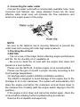
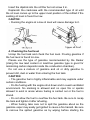
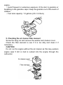
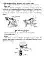
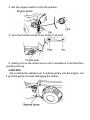
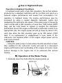
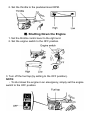
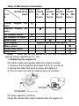
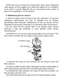
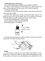
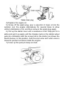
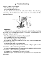
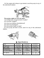
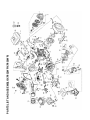
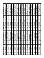
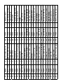
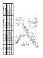
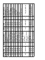
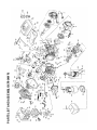
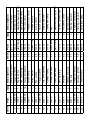
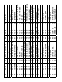
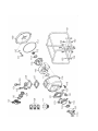
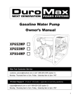
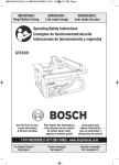
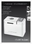
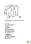
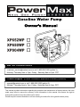
Gasoline Water Pump
Owner’s Manual
Max Tool Customer Service
[email protected] or call 1-800-629-3325 (option 3)
Monday -Thursday 6am to 7pm, Friday - Saturday 6am to 3pm. PST
Product Support (Product: information, application & warranty questions)
[email protected] or call 1-800-629-3325 (option 3)
Monday -Thursday 6am to 7pm, Friday - Saturday 6am to 3pm. PST
This manual provides information regarding the operation and maintenance of these products. We have
made every effort to ensure the accuracy of the information in this manual. We reserve the right to
change this product at any time without prior notice.
Please keep this manual available to all users during the entire life of the gasoline water pump.
CONTENTS
ĉ. General Safeguards ĂĂĂĂĂĂĂĂĂĂĂĂĂĂĂĂĂ 1
Ċ. Location of Component Parts ĂĂĂĂĂĂĂĂĂĂĂĂĂ 3
ċ. Operation before Starting Up ĂĂĂĂĂĂĂĂĂĂĂĂĂ 4
Č. Starting of Engine ĂĂĂĂĂĂĂĂĂĂĂĂĂĂĂĂĂĂ 9
č. Use in Highland Areas ĂĂĂĂĂĂĂĂĂĂĂĂĂĂĂĂ 11
Ď. Operation of Water Pump ĂĂĂĂĂĂĂĂĂĂĂĂĂĂ 12
ď. Shutting Down the Engine ĂĂĂĂĂĂĂĂĂĂĂĂĂĂ 13
Đ. Maintenance ĂĂĂĂĂĂĂĂĂĂĂĂĂĂĂĂĂĂĂĂ 14
đ. Transportation and Storage ĂĂĂĂĂĂĂĂĂĂĂĂĂĂ 19
Ē. Troubleshooting ĂĂĂĂĂĂĂĂĂĂĂĂĂĂĂĂĂĂĂ 21
ē. Specifications ĂĂĂĂĂĂĂĂĂĂĂĂĂĂĂĂĂĂĂĂ 23
ĉ. General Safeguards
Safety Precautions
Please read this operation manual to have a
thorough understanding of the content there
before use the product. Failure to do so may
lead to personal injury or mechanical damage.
Before starting the engine, perform inspections according to the
procedures described on pre-operation inspections to avoid
accidents and damage to your machine.
For safety, never attempt using this GEP (gasoline engine
powered) water pump to deliver inflammable or corrosive liquids
(such as gasoline and acids). Likewise, corrosive mediums,
seawater, chemical solvents, alkaline liquids (such as used gasoline,
liquor and honey) should be avoided.
Place the water pump on a solid, level position surface to avoid
tilting or turnover that may give rise to spilling of fuel.
To prevent fire hazards, keep the pump well ventilated during
operation and maintain a distance of at least l meter between the
machine and the wall or other machines. Keep away from
inflammable substances.
Do not allow children and pets to enter the working area as this
may increase the chance of their getting burned by hot surfaces of
the operating parts.
Know how to stop the water pump quickly how to operate the
controls. Do not use the pump against the prescribed operating
rules.
WARNING˖
Safety Precautions
The gasoline fuel is highly inflammable and may explode under
certain conditions.
Do the fueling with the engine shut down and in a well-ventilated
environment. No smoking is allowed and no open fire or sparks
allowed to exist in areas where fueling is carried out or the fuel is
stored.
Do not allow the fuel to overflow the fuel tank. Be sure to recap
the tank and tighten it after refueling.
When fueling, take care not to spill the gasoline about as the
gasoline vapor may easily get ignited to cause a fire hazard. Be sure
to remove the spilled gasoline as by wiping before starting the
engine.
Do not run the engine indoors or in a poorly ventilated space as
the exhaust gas produced by the running engine contains toxic
carbon monoxide that may cause the loss of personal
consciousness or even death.
Ċ. Location of Component Parts
ċ. Operation before Starting Up
1. Connecting the water inlet
Connect the water inlet with a commercially available hose,
connector and fastener clip. The inlet hose must be a continuous
non-foldable structure with a length not more than required and
should be placed near to the source of water so as to achieve the
pump should be fitted to the end of the hose with the hose connector
as shown in the figure below.
CAUTION: Before pumping water, attach the filter to the end of the
hose to filter out foreign matters in the water, the presence of which
may cause clogging and damage to the wane wheel.
NOTE: The hose connector and fastener clip should be securely
fastened to prevent air leaks and reduction in suction power. A loose
hose will reduce the pump performance and self-suction capacity.
2. Connecting the water outlet
Connect the water outlet with a commercially available hose, hose
connector and fastener clip. Large diameter hoses are the most
effective while small ones will increase the flow resistance and
reduce the output power of the pump.
NOTE:
Be sure to the fastener clip is securely fastened to prevent the
outlet hose from coming off under high water pressure.
3.Checking the oil level
CAUTION:
gThe oil is one of the major factors affecting engine performance
and life. Do not use dirty oil or vegetable oil.
gBe sure to check the oil level with the engine shut down and
placed on a level surface.
Please use the SE15-40, 4-stroke engine oil as recommended.
Please use the type of oil with a proper viscosity according to the
local average temperature.
Oil shortage alarm system (OSAS) (installation position)
The OSAS is designed to avoid damage of the engine due to the
shortage of oil in the crankcase. The system will automatically shut
down the engine just before the crankcase oil level drops down to
the minimum line of safety (with the engine switch staying in the ON
position).
If the engine is shut down and cannot be started again, check the
oil level before initiating further troubleshooting procedures.
Remove the oil dipstick and wipe it dry.
Insert the dipstick into the oil filler but not screw it in.
Replenish the crankcase with the recommended type of oil until
the oil level comes up to the upper most position of the refilled if the
existing oil level is found too low.
CAUTON:
gRunning the engine at a low oil level will cause damage to it.
4. Checking the fuel level
Uncap the fuel tank and check the fuel level. Pouring gasoline if
the fuel level is found too low.
Please use the type of gasoline recommended by the Dealer
(Using the low lead content or lead-free gasoline type is good for
minimizing carbon deposits inside the combustion chamber).
Do not use a mixture of gasoline and oil or dirty gasoline to
prevent dirt, dust or water from entering the fuel tank.
CAUTION:
gThe gasoline fuel is highly inflammable and may explode under
certain conditions.
gDo the fueling with the engine shut down and in a well-ventilated
environment. No smoking is allowed and no open fire or sparks
allowed to exist in areas where fueling is carried out or the fuel is
stored.
gDo not allow the fuel to overflow the fuel tank. Be sure to recap
the tank and tighten it after refueling.
gWhen fueling, take care not to spill the gasoline about as the
gasoline vapor may easily get ignited to cause a fire hazard. Be sure
to remove the spilled gasoline as by wiping before starting the
engine.
gAvoid frequent or extensive exposure of the skin to gasoline or
breathing in the gasoline vapor. Keep the gasoline out of the reach of
children.
gFuel tank capacity: 1.0 gallons (US. 3.6 liters)
5. Checking the air cleaner filter element
Screw the wing nut and remove the washer and cleaner cover.
Check the filter element to see if it is too dirty and clean it if
necessary.
CAUTION:
Do not run the engine without the air cleaner as this may quicken
engine wear if dirt or dust is sucked into the engine through the
carburetor.
6. Checking and filling the pump with cooling water
The pump must be filled with water before it is put to operation.
CAUTION:
gDo not attempt running the pump without cooling water or the
pump will get overheated. Extensive running without cooling water
may also damage the air tightness of the pump. If the pump is found
running dry, stop the engine and pouring in water when it cools
down.
Č. Starting engine
1. Turn on the fuel tap (by setting it to the ON position).
2. Close the choke.
NOTE:
gThe choke is not required when starting the engine warm or the
ambient temperature is rather high, (i.e. keep the choke open when
starting the engine).
3. Set the engine switch to the ON position.
4. Turn the throttle control lever slowly to the left.
5. Gently pull up the starter lever until a resistance is felt and then
quickly pull it up.
CAUTION:
gDo not allow the starter lever to retract quickly into the engine. Let
it go back gently to avoid damaging the starter.
č.Use in Highland Areas
Operation in Highland Conditions
In highland areas (with a high ASL elevation), the air-fuel mixture
produced by a standard carburetor will be too thick and result in a
reduced engine performance and soared fuel consumption. For
operation in highland areas, the engine performance may be
increased by using a smaller diameter carburetor nozzle and
readjusting the carburetor idle speed. If the water pump is frequently
used in areas with a ASL elevation of more than 1800 meters (6000
feet), ask the local dealer to replace or readjust the carburetor
beforehand. Even if the engine is fitted with a carburetor nozzle of an
appropriate size, the engine power will still go down by about 3.5%
each time when the ASL elevation goes up by 305 meters (1000
feet). If no replacement or readjustment is ever made of the
carburetor, the highland effect of the engine output power will be
even more obvious.
CAUTION:
gUsing the water pump in areas where the ASL elevation is lower
than suitable for the carburetor nozzle will lead to a decreased
engine performance and overheating of the engine and even cause
serious damage to the engine due to an extremely thin air-fuel
mixture.
Ď. Operation of the Water Pump
1. Gradually open the choke after the engine warms up.
2. Set the throttle to the predetermined RPM.
ď. Shutting Down the Engine
1. Set the throttle control lever to the right end.
2. Set the engine switch to the OFF position.
3. Turn off the fuel tap (by setting to the OFF position).
NOTE:
gTo shut down the engine in an emergency, simply set the engine
switch to the OFF position.
Đ. Maintenance
Periodic inspections and fine-tuning are simply indispensable to
keep the water pump working with high performance and regular
maintenance may also lengthen the pump life. Supplied in the table
on the next page are intervals at which the schedules maintenance
jobs are to be done.
WARNING:
gBefore any maintenance attempt, be sure to shut down the
engine. If the maintenance job has to be done with the engine at
work, it should take place in a well-ventilated space as the exhaust
gas contains toxic carbon monoxide that causes the loss of personal
consciousness or even death.
CAUTION:
gIn cases when the pump is used to suck up seawater, be sure to
flush it with fresh water immediately after use to minimize corrosion
and remove deposits.
gAlways use the original parts and relevant tools supplied with the
machine to carry out maintenance. Failure to do this may cause
damage to the pump.
NOTE:
Ł Inspection and maintenance should take place more frequently
if the pump is used in a dirty environment.
ł Leave the following inspection and maintenance jobs to the
authorized dealers unless you, the user, have the relevant tools and
necessary DIY skills. In the latter case, refer to service manual.
Table of Maintenance Schedules
Normal Each Per
Per
Per
maintenance time month month month
Item
perio
or 20 or 50 or 100
d
hours
hours
hours
Per
month
or 300
hours
ƻ
Check engine oil
lever
ƻ
ƻ
Replace engine oil
lever
ƻ
Air cleaner check
Air cleaner for clean
ƻ
Spark plug
Fuel supply
Replace per every two years
Wane wheel
Pump case cover
Water inlet
Note: “*” items will be maintained with the help of dealers
general power machinery Co., Ltd.
1. Replacing the engine oil
Oil drains easily and quickly while the engine is warm.
1. Remove the oil dipstick and drain bolt to let out the oil.
2. Screw the drain bolt back in place and tighten it.
3. Pour in clean oil until the desired level is reached.
Oil sump capacity: 0.6 liters
Clean the hands with soap if stained with the engine oil.
ƻ*
ƻ*
ƻ*
ƻ*
from
NOTE: Be sure to keep the environment clean when disposing
used engine oil. We suggest you collect the waste oil in a container
to be sent to a waste disposal site or a recycling service center of
spill it in the garbage or on the ground.
2. Maintaining the air cleaner
A dirty air cleaner will let less air into the carburetor. To prevent
carburetor malfunctions, be sure to maintain the air cleaner
periodically. More frequent maintenance of the air cleaner will be
necessary if the pump is working in an extremely dirty environment.
DO not clean the air cleaner with a low ignition point solvent
because it may get enflamed or even explode under certain
circumstances.
CAUTION: Do not use the water pump without an air cleaner. The
dirt or dust if sucked into the engine may quicken engine wear.
1) Unscrew the wing nut and remove the air cleaner cover and
filter element.
2) Clean the filter element with a detergent solution inflammable or
with a high ignition point and let it dry thoroughly after cleaning.
3) Immerse the filter element into clean oil and then squeeze out
the excessive amount of oil.
4) Put the filter element as well as the air cleaner back in place.
3. Maintaining the spark plug
The recommended type of spark plug is NHSP LD P6RTCU.
To ensure normal operation of the engine, the spark plug should
have a correct gap and should remain free of carbon deposits.
1) Remove the plug cap.
The muffler may be very hot if the engine is still running. Take care
not to touch the muffler.
2) Check the spark plug visually. Discard the spark plug if it is
obviously worn out or the insulation ring on it is broken or cracked.
Clean the spark plug with a brush when put it back in place.
3) Check the plug gap with a feeler gauge.
Vary the gap by moving the side electrode.
Normal plug gap: 0.70~0.80mm
4) Check the plug O-ring for normal condition. Screw it in with the
plug wrench to protect the plug thread.
NOTE:
gIn the case of screwing in a new spark plug, tighten it by an
additional 1/2 screw turn after the plug reaches and pushes on the
O-ring, while in the case of a used spark plug, an additional 1/2~1/4
screw turn is necessary.
CAUTION:
g Make sure the spark plug is properly tightened. Improper
tightening may cause the engine to be overheated or damaged.
Never use spark plugs with an incorrect thermal value range.
đ. Transportation and Storage
CAUTION:
gTo avoid causing a fire hazard, let the engine cool down before
transportation or indoor storage of the pump.
gBefore transporting the pump, set the fuel tap to the OFF position
and place the pump body in a level position to prevent the fuel from
spilling out. The spilled gasoline or the gasoline vapor may get
ignited.
Note and do the following before storing pump for an extended
period of time:
1) Make sure the storage area is free of moisture or dust.
2) Ch\lean the inside of the pump.
The pump may get clogged if it is used to suck up water containing
such matters as earth, sand or heavy fragments.
Before storing, clean the pump by sucking up clean water or
otherwise the wane wheel may be damaged when the pump is put to
use again. After cleaning, unscrew the water drain plug to drain off
the water from inside the pump casing as much as possible. Then
screw the drain plug back into place.
3) Drain off the fuel.
a. Turn off the fuel tap (OFF position), unscrew the drain screw
from the carburetor float chamber to drain off the fuel from inside the
carburetor and collect the gasoline in a suitable container.
b. Turn on the fuel tap (ON position) and collect the gasoline in a
suitable container.
c. Screw the carburetor fuel drain screw back into place.
4) Replace the engine oil.
5) Screw off the spark plug, pour a spoonful of clean oil into the
cylinder, turn the engine alternatively for several times to allow
uniform distribution of oil, and then screw in the spark plug again.
6) Pull up the starter lever until a resistance is felt. Stop pull for a
while and pull it up again until the triangle mark on the starter wheel
gets into collimation with the screw hole in the starter (as shown the
sketch below). In this position, both the inlet valve and outlet valve is
closed to prevent corrosion inside the engine.
7) Cover up the pump to keep out dust.
Ē. Troubleshooting
Engine unable to get started:
1) Is there enough fuel?
2) Is the fuel tap turned on?
3) Has the fuel reached the carburetor? Make the check by
unscrewing the oil drain screw from under the carburetor with the
fuel tap turned on.
WARNING:
gShould there be a spill of fuel, be sure to clean it before checking
the spark plug and start the engine or otherwise the spilled fuel or
fuel vapor may get ignited
4) Is the engine switch set to the ON position?
5) Is there enough oil in the crankcase?
6) Is the spark plug generating sparks?
a. Uncap the spark plug, clear off the dirt from around the plug and
remove the spark plug.
b. Fit the spark plug into the plug cap.
c. Turn on the engine with the side electrode and pull up the starter
lever to see if there is sparks generated.
d. Ground the engine with the side electrode and pull up the starter
lever to see if there is sparks generated.
e. Replace the spark plug if no spark is found.
Start the engine as directed in the operation manual if sparks are
generated.
7) If the engine still refuses to get started, send the pump to any of
the authorized dealers.
The pump unable to such up water:
1) Is it filled with enough amount of water?
2) Is the filter clogged?
3) Is the hose fastener clip tightened?
4) Is the hose damaged?
5) Is the suction head too high?
6) If the pump still fails to work, send it to any of the authorized
dealers.
ē. Specifications
Type
XP652WP
XP650WP
XP904WP
Engine type
XP6.5HP
XP6.5HP
XP9.0HP
Max. Power
4.7kw(6.5HP)
4.7kw(6.5HP)
6.5kw(9.0HP)
196cc
196cc
270cc
1.0 Gallons
1.0 Gallons
1.7 Gallons
0.63 US. Qt.
(0.6L, 20fl oz.)
0.63 US. Qt.
(0.6L, 20fl oz.)
Displacement
Fuel tank capacity
Oil capacity
1.16 US. Qt
(1.1L, 37fl oz.)
Water intake pipe dia.
2ą
3ą
4ą
Water output pipe dia.
2ą
3ą
4ą
3600rpm
3600rpm
3600rpm
Max. overhead lift
92ft
98ft
98ft
Max. suction lift
26ft
26ft
26ft
158 GPM
220 GPM
427 GPM
18.7h15.6h
15.4(in.)
21.3h17.5h
19.3(in.)
25.2h20.7h
22.3(in.)
Revolution
Max. flow rate
Size
PARTS LIST AND ASSEMBLY(XP652WP/XP650WP)
Part
21100
GB5787-86
12302
12310
GB6177-86
19005
19001
81200
87500
12302
19002
19003
81100
GB5789-86
13203
12217
900008
12200
17300
GB5787-86
17316
Item
1
2
3
4
5
6
7
8
9
10
11
12
13
14
15
16
17
18
19
20
21
2
1
13
1
1
2
2
2
1
1
1
1
1
1
1
1
1
1
1
4
1
Qty
Lever comp, choke
Flange bolt M6×12
Carburetor assy.
Crank case assy.
Oil seal, 25×41×6
Washer, drain lug
Bolt, drain lug
Flange bolt M6×25
Coil assy. ignition
Switch wire
Plate, side
Clip. Wire darkness
Amplifier
Flywheel comp
Fan, cooling
Pulley, starter
Flange nut M14
Fan, cover comp
Engine switch
Flange bolt M6×8
Starter comp, recoil
Description
42
41
40
39
38
37
36
35
34
33
32
31
30
29
28
27
26
25
24
23
22
Item
90007
91005
GB5789-86
90006
11240
16004
16001
16007
16002
GB6177-86
16003
GB5789-86
16005
92001
11250
90005
91004
90004
90003
90002
19003
Part
1
2
4
1
1
1
1
2
1
5
1
1
1
1
1
1
2
1
1
1
1
Qty
Casket, cylinder head
Bolt head, M8×32
Flange bolt M8×60
Exhaust piper
Cover comp, head
Cover comp, air cleaner
Element, air cleaner
Nut, M6
Separator, air cleaner
Flange nut M6
Case comp, air cleaner
Flange bolt M6×20
Seal, air cleaner
Casket, muffler
Head comp, cylinder
Packing, insulator
Bolt head, 6×112
Insulator, carburetor
Packing, carburetor
Packing air cleaner
Shroud comp
Description
92002
GB/T276-94
11202
15002
15001
11215
11214
GB/T 6170
18003
18002
11204
18001
18101
11206
11205
11211
11216
11208
15100
11209
11206
11212
43
44
45
46
47
48
49
53
54
55
50
51
52
56
57
58
59
60
61
62
63
64
1
2
1
1
1
1
1
2
2
1
1
2
1
1
2
2
1
2
2
1
2
2
Retainer, EX. Valve spring
Spring, valve
Valve, EX.
Camshaft assy.
Valve, IN.
Seat, valve spring
Retainer, IN. Valve spring
Arm, valve rocker
Nut, pivot adjusting
Casket EX. Pipe
Muffler
Nut, Arm, valve rocker
Protector, muffler
Arrester, spark
Nut, M8
Bolt, pivot
Plate, push rod guide
Rod, push
Lifter, valve
Plug, spark
Radial ball bearing (6025
Pin, dowel, 10×16
86
85
84
83
82
81
80
79
78
77
76
75
74
73
72
71
70
69
68
67
66
65
17002
91003
17001
12230
87400
GB5789-86
13000
GB/T 99-88
17200
90001
92003
12102
GB5789-86
12100
12103
13101
13100
GB847-85
13104
13015
13106
11213
1
1
1
1
1
2
1
1
1
1
2
1
6
1
1
1
1
5
1
2
1
1
Spring, throttle return
Bolt, governor arm
Spring, governor
Governor assy.
Switch assy. oil level
Flange bolt M6×12
Crankshaft comp
Key, 25×18
Control assy.
Packing, case cover
Pin, dowel, 8×14
Cap assy. oil filler
Flange bolt M8×32
Crankcase cover
Cap, oil hole
Piston
Ping set, piston
Screw, tapping M5×8
Pin, piston
Clip, piston pin
Connecting rod assy.
Rotator, valve
17004
17003
91009
12208
17102
91002
87
88
89
90
91
92
2
1
1
1
1
1
Clip, tube
Rubber, supporter
Shaft, governor assy.
Tube, fuel
Rod, governor
Arm, governor
97
96
95
94
93
17110
17130
17120
17101
GB5789-86
1
1
1
1
1
Fuel filler cap
Filter, fuel
Tank fuel
Joint, fuel tank
Flange bolt M6×30
Part
TS1300
TS1301
GB5787-86
TS1006
TS1303
TS1101
TS1100
TS1008
TS1103
TS1001
GB5787-86
TS1013
TS1012
TS1003
Item
98
99
100
101
102
103
104
105
106
107
108
109
110
111
1
2
2
12
1
1
1
1
1
1
1
4
4
1
Qty
Flapper valve gasket
Plug
124
123
122
Flange Bolt M8×25
(XP652WP)
Flange Bolt M10×25
(XP650WP)
O-ring, Plug
121
120
119
118
117
116
115
114
113
112
Item
Pump case housing
Ring, Volute casing
Volute casing
Impeller, water pump
Mechanical seal B
Mechanical seal A
O-Ring, water pump
Flange Bolt M8×53
Washer
Assembly, pump cover
Description
GB5787-86
TS2111
GB5789-86
GB6177-86
TS4100
TS2030
TS2020
TS1004
TS1005
TS2003
TS2002
TS2001
TS1002
Part
4
4
4
4
1
1
3
1
1
2
2
2
1
Qty
Flange Bolt M6×16
Rubber pad, damping
Flange bolt M8×35
Flange nut M8
Frame
Strainer
Hose Band
Discharge port
Discharge gasket
Hose Coupling
Hose Joint
Coupling Packing
Suction port
Description
PARTS LIST AND ASSEMBLY(XP904WP)
3
1
GB5787-86
11082
12310
GB5787-86
19003
19005
19001
GB6177-86
23007
81200
12215
12200
12203
87500
12217
87601
GB5789-86
81100
81103
2
3
4
5
6
7
8
9
10
11
12
13
14
15
16
17
18
19
20
1
1
2
1
2
1
2
1
2
1
1
1
1
1
1
12
1
1
21100
1
Qty
Part
Item
Grommet cord
Coil assy. ignition
Flange bolt M6×25
Clip, wire
Washer, drain lug
Amplifier
Bolt, drain lug
Crank case assy.
Oil seal, 35×52×8
Flywheel comp
Clip. Wire harness
Flange nut M16
Fan, cooling
Pulley, starter
Shroud comp
Flange bolt M6×12
Fan, cover comp
Engine switch
Flange bolt M6×8
Starter comp, recoil
Description
40
39
38
37
36
35
34
33
32
31
30
29
28
27
26
25
24
23
22
21
Item
23000
23002
23001
23003
11218
12220
11219
GB/T276-94
GB/T 99-88
13000
13200
12200
12221
GB6177-86
12209
12212
12208
GB/T276-94
12216
81102
Part
1
1
1
1
2
2
1
2
1
1
1
1
1
1
1
1
1
2
1
Qty
Carburetor assy.
Packing, carburetor
Insulator, carburetor
Packing, insulator
Bolt head, 8×111
Pin, dowel, 12×20
Casket, cylinder head
Radial ball bearing (6207)
Key
Crankshaft comp
Weight, balancer
Switch assy. oil level
O-ring, 14mm
Flange nut M10
Washer, 8.2×17×0.8
Pin, lock, 10mm
Shaft, governor arm
Radial ball bearing (6202)
Oil seal, 8×14×5
Cord stop switch
Description
22000
23008
GB6177-86
12005
GB5789-86
12010
16007
16008
12010
12004
12007
11242
11243
11240
11241
GB5789-86
12001
11250
11217
11202
15100
15002
41
42
43
44
45
46
47
48
49
50
51
52
53
54
55
56
57
58
59
60
61
62
2
1
1
2
1
1
4
1
1
1
1
1
1
1
2
2
1
1
1
5
2
1
Lifter, valve
Camshaft assy.
Plug, spark
Bolt head, M8×34
Head comp, cylinder
Tube, breather
Flange bolt M10×80
Exhaust piper
Cover comp, head
Washer comp head cover
Bolt, head cover
Cover comp, air cleaner
Separator, air cleaner
Element assy. air cleaner
Washer, drain lug
Nut, M6
Seal, air cleaner
Flange bolt M6×20
Case comp, air cleaner
Flange nut M6
Packing, air cleaner
Stay manual choke
84
83
GB5789-86
GB847-85
13030
82
7
5
1
1
13020
81
1
13010
1
1
1
6
2
2
2
1
1
2
1
1
2
1
2
1
1
13200
13202
GB6177-86
11206
11204
11205
11212
11213
11214
11215
11211
11206
11216
15001
11209
11208
13003
80
79
78
77
76
75
74
73
72
71
70
69
68
67
66
65
64
63
Flange bolt M8×35
Screw, tapping M5×8
Muffler guard
Muffler
Arrester, spark
Muffler stay
Pipe comp EX.
Casket (B) EX. Pipe
Flange nut M8
Nut, pivot adjusting
Nut, Arm, valve rocker
Arm, valve rocker
Retainer, EX. Valve spring
Rotator, valve
Bolt, pivot
Plate, push rod guide
Retainer, IN. Valve spring
Spring, valve
Seat, valve spring
Rod, push
Valve, EX.
Valve, IN.
12103
12100
12214
12213
121102
12230
13105
13104
13100
13101
13106
17220
17001
85
86
87
88
89
90
91
92
93
94
95
96
97
1
1
1
1
1
1
2
1
1
2
1
1
1
Spring, governor
Control assy.
Connecting rod assy.
Piston
Ping set assy. piston
Pin, piston
Clip, piston pin
Governor kit
Cap assy. oil filler
Pin, dowel, 8×12
Packing, case cover
Crankcase cover
Cap, oil hole
109
108
107
106
105
104
103
102
101
100
99
98
1
14004
1
1
1
17102
14302
14300
1
1
14100
17101
1
14102
2
1
14200
GB5789-86
1
1
1
17004
17005
17002
Fuel filler cap comp
Fuel filter
Rubber joint, fuel tank
Joint, fuel tank
Outlet pipeij4.5×235
Fuel cock
Rubber, supporter
Flange bolt M8×25
Fuel tank
Arm, governor
Bolt, governor arm
Spring, throttle return
Part
TS1300
TS1301
GB5787-86
TS1006
TS1303
TS1101
TS1100
TS1008
TS1103
TS1001
GB5787-86
TS1013
TS1012
TS1003
Item
109
110
111
112
113
114
115
116
117
118
119
120
121
122
1
2
2
12
1
1
1
1
1
1
1
4
4
1
Qty
Flapper valve gasket
Plug
O-ring, Plug
Flange Bolt M10×25
Pump case housing
Ring, Volute casing
Volute casing
Impeller, water pump
Mechanical seal B
Mechanical seal A
O-Ring, water pump
Flange Bolt M8×45
Washer
Assembly, pump cover
Description
135
134
133
132
131
130
129
128
127
126
125
124
123
Item
GB5787-86
TS2111
GB5789-86
GB6177-86
TS4100
TS2030
TS2020
TS1004
TS1005
TS2003
TS2002
TS2001
TS1002
Part
4
4
4
4
1
1
3
1
1
2
2
2
1
Qty
Flange Bolt M6×16
Rubber pad, damping
Flange bolt M10×35
Flange nut M10
Frame
Strainer
Hose Band
Discharge port
Discharge gasket
Hose Coupling
Hose Joint
Coupling Packing
Suction port
Description