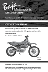
1
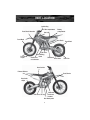
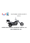
X250 Dirt Bike
Read this manual carefully. It contains important safety information. No on
under the age 16 should operate this dirt bike without adult supervision.
OWNER’S MANUAL
Minimum Age Requirement: 16
Model 250cc
REV. C
020509
Always wear a helmet. It could save your life.
Do not remove this operator’s manual from this vehicle.
Please obtain, review and follow provincial/municipal government acts and
regulations pertaining to owning and operating an off-road vehicle.
Congratulations on your purchase of the BAJA INC. X250 Dirt Bike.
Your bike is warranted to be free of manufacturing defects in the material
and workmanship for a period of 90 days from the date of purchase.
During the warranty period BAJA, INC. will at its option, repair, provide
replacement parts or replace your Baja Motorsports 250cc Dirt bike at
no charge. This warranty does not cover normal wear items or damage
caused by neglect or misuse of the product.
Engine Warranty – 90 days
Frame Warranty – 90 days
Warranty is void if:
Frame is bent or broken due to abuse
Wheels are bent or broken
Fender bent or broken due to abuse
Any sign of impact, accident, jumping, spin-outs or roll over.
BAJA, INC. is not liable for any damage claim or liability claim person or
otherwise resulting from the operation of this product in any way.
Should you experience a problem with your vehicle, please call the Baja
INC. customer service line toll free at 1-888-863-2252 between the hours of
7am and 5pm Monday through Friday MST (Mountain Standard Time). MDT
(Mountain Daylight Time) during daylight saving time. You will be instructed
how to proceed.
A COPY OF THE SALES RECEIPT IS REQUIRED.
II
!!
WARNING
This manual should be considered a permanent part of
the vehicle and should remain with the vehicle when
resold or otherwise transferred to a new user or operator.
The manual contains important safety information and
instructions which should be read carefully before
operating the vehicle.
! WARNING
The engine exhaust from this product contains
chemicals known to the State of California to cause
cancer, birth defects or other reproductive harm.
CALIFORNIA PROPOSITION 65
III
TABLE OF CONTENTS
SAFETY ...............................................................................................................2
SAFE OPERATION ......................................................................................3
SAFETY GEAR ............................................................................................4
WARNING LABEL PLACEMENT ................................................................5
SPECIFICATIONS................................................................................................6
PART LOCATION.................................................................................................7
CRANK CASE BREATHER .................................................................................9
OPERATION ........................................................................................................10
FUEL FILLING .............................................................................................10
FUEL VALVE ................................................................................................10
ENGINE BREAK-IN .....................................................................................11
SWITCHES ON RIGHT HANDLE BAR .......................................................11
LEFT HANDLEBAR, CLUTCH LEVER .......................................................12
RIGHT HANDLEBAR, FRONT BRAKE LEVER AND
THROTTLE TWIST GRIP.............................................................................12
REAR FOOT BRAKE ...................................................................................12
GEAR SHIFTING .........................................................................................13
PRE-RIDE INSPECTION .............................................................................14
STARTING ENGINE .....................................................................................15
BATTERY INSTALLATION ..................................................................................16
MAINTENANCE ...................................................................................................19
CHECKING ENGINE OIL ............................................................................19
CHANGING ENGINE OIL AND CLEANING SCREEN ................................20
CHECK UP OF SPARK PLUG.....................................................................20
VALVE CLEARANCE...................................................................................21
CHECKING & CLEANING AIR FILTER .......................................................22
ADJUSTING THE THROTTLE CABLE .......................................................23
ADJUSTING THE CARBURETOR ..............................................................23
FRONT HYDRAULIC DISK BRAKE ............................................................24
REAR HYDRAULIC DISK BRAKE ..............................................................24
CLUTCH ADJUSTMENT .............................................................................25
ADJUSTMENT OF CHAIN ...........................................................................26
LUBRICATING CHAIN .................................................................................26
TORQUE SPECIFICATIONS .......................................................................27
INSPECTION AND MAINTENANCE CHART ..............................................28
TROUBLE SHOOTING ........................................................................................30
VEHICLE WASHING ............................................................................................31
INSTRUCTIONS FOR STORAGE .......................................................................32
RESUMPTION OF SERVICE AFTER STORAGE .......................................33
SERIAL NUMBER LOCATION ............................................................................34
EMISSION CONTROL SYSTEM WARRANTY ....................................................35
1
SAFETY
Please read this manual and follow all instructions carefully. To emphasize special
information, the symbol and the words WARNING or CAUTION have special
meaning. Pay attention to WARNINGS and CAUTIONS.
WARNING
Indicates a potential hazard that could result in death or injury.
! CAUTION
Indicates a potential hazard that could result in vehicle damage.
NOTE: Indicating special information which makes maintenance easier and/or
instructions clearer.
WARNING and CAUTION are arranged like this:
WARNING-or-CAUTION
The first part will identify a POTENTIAL HAZARD.
The second part will describe WHAT COULD HAPPEN if you ignore
the WARNING or CAUTION.
The third part will describe HOW TO AVOID THE HAZARD.
This user’s manual contains important safety and maintenance information. Read
it carefully before riding. Failing to follow the warnings contained in this manual
could result in INJURY or DEATH.
It is important that this manual remain with the vehicle when you transfer it to
another user or owner.
All information, illustrations, photographs and specifications contained in
this manual are based on the latest product information available at the time
of publication. Due to improvements or other changes, there will be some
discrepancies in this manual. We reserve the right to make product changes at
any time, without notice and without incurring any obligation to make the same or
similar changes to the vehicle previously built or sold.
2
SAFETY
SAFE OPERATION
Rules for Safe Operation
A pre-operation check must be conducted before starting the engine. This check will
insure safety, prevent mishaps, and prevent damage to components.
It is strongly suggested that all operators take a certified motorcycle rider’s course prior
to operating the vehicle.
Full attention is required during driving; paying close attention to the following points
to avoid any injury to you by other motorized vehicles:
·
Always wear an approved DOT (Department of Transportation) helmet. It is a
proven fact that helmets reduce the number of severe head injuries. Never ride, or
let a child ride without a DOT approved motorcycle helmet.
·
Always wear protective riding gear, helmet, eye protection, long sleeve shirt, long
pants, riding boots and gloves.
·
Always watch for off-road hazards. Be aware of unexpected turns, drop off’s,
rocks and other hazards. Keep speed low enough to allow time to react to hazards
and changing conditions.
·
Never use alcohol or drugs before or during operation. Alcohol and drugs can
significantly reduce your ability to make good judgements and ride safely.
·
Do not drive too close to other vehicles.
·
Never carry a passenger. This dirt bike is for one operator only.
·
Never operate this dirt bike at night. Night is defined as the period of time 30
minutes before sunset to 30 minutes after sunrise.
·
Driving at high speeds is the cause of many accidents; do not drive at a speed that
the actual situation does not permit.
·
Never allow anyone under the age of 16 to operate this dirt bike. Physical, mental
and emotional maturity are requirements for safe riding. Rider must be able to
judge speed, distances and be able to react to changing conditions with good
hand, foot and eye coordination.
·
Always avoid operating an this dirt bike on paved surfaces, including; sidewalks, paths,
parking lots, driveways, streets, roads, and highways. Never operated this or any Off
Road Vehicle on a public street, road or highway where motor vehicles are in
operation.
3
SAFETY
·
Always keep your dirt bike in safe operating condition. Inspect dirt bike before
each ride and perform all recommended maintenance and pre-ride inspections.
·
Never overload dirt bike. Maximum weight capacity is 250 lbs. (113 kg).
SAFETY GEAR
A DOT approved motorcycle helmet is the most important part of your safety
gear. A DOT approved motorcycle helmet can help prevent a serious head injury.
Choose a helmet that fits snug. Motorcycle dealers can help in selecting a good
quality helmet which fits properly.
! WARNING
Operating this dirt bike without wearing an approved DOT motorcycle
helmet, eye protection and protective clothing could be hazardous.
Operating without an approved DOT motorcycle helmet or eye protection
increases your chances of severe head injury or death in an accident.
Operating without protective clothing also increases your chances of severe
injury in an accident.
Always wear an approved DOT motorcycle helmet which fits properly.
Always wear eye protections (goggles or face shield). You should also wear
gloves, boots, long sleeve shirt or jacket and long pants.
You should wear eye protection when you ride. If a rock or a branch hits your
eyes, you could be severely injured. Wear goggles or a face shield.
Wear proper clothing when you ride. The proper clothes can protect you from
injury. Wear a good pair of gloves, strong boots that are over the ankle, long
pants and a long sleeve shirt.
Loose clothes are not suitable for motorcycle driving or riding as they may
get caught on the operating lever, kick lever, footrest or wheel, resulting in
danger.
MODIFICATION OF THE VEHICLE
! CAUTION
Never perform any unauthorized modifications to this vehicle. Only use
original replacement part which can be obtained through Baja Inc.
888-863-2252.
4
WARNING LABEL PLACEMENT
OFF ROAD USE ONLY
This vehicle is manufactured and
designed for off road use only. It does
not conform to federal motor vehicle
safety standards.
Operation on public streets, roads, or
highways is illegal
5
SPECIFICATIONS
Description
Data
Description
Data
Overall Length
1920mm
( 75 1/2 in.)
Cylinder bore X
Stroke
67mm X 65mm
Overall Width
820mm
(32 1/4 in.)
Compression
Ratio
9.2:1
Overall Height
1060mm
(41 3/4 in.)
Output Max
11.5kw / 6500 RPM
15.2hp / 6500 RPM
Wheelbase
1320mm
(52 in.)
Displacement
244cc
Dead weight
G.W/N.W
116.5kg/97kg
(257 lbs./213 lbs.)
Idle Speed
1500 r/min ±
100 r/min
Payload
113kg
(250 lbs.)
Spark Plug
A7TC (Torch)
D8EA (NGK)
Gap .6mm - .7mm
(.024” - .028” )
Ground
Clearance
250mm
(9.84 in.)
Front Wheel
70/10-19
22psi
Rear wheel
90/100-16
28psi
Ignition
CDI
Max Speed
≤ 90KM/H
(56 MPH)
Transmission
5 gear mesh
Fuel capacity
and type
3.35L
(.88 gal.)
92 octane or
higher
6
PART LOCATION
PARTS & SUBASSEMBLIES
Clutch Lever
Brake fluid reservoir
Front brake lever
On/Off switch
Electric start
button
Throttle twist
grip
Fuel tank cap
Ignition key switch
7
PART LOCATION
Ignition Key
Air filter compartment
Front Shock Absorber
Gas Cap
Front Wheel
Front brake
caliper
Battery
compartment
Rear Shock
Fuel Valve
Gear Shifting
Drive
Pedal
Side
Stand
Choke lever
Drive Chain
on Carburetor
Rear Wheel
Rear Fork
Seat Cushion
Exhaust Silencer
Front Shocks
Rear brake
caliper
Carburetor
Crank case
Kick Lever Oil Cap
breather
Rear Brake pedal
8
CRANKCASE CREATHER
When shipped from the factory, the crankcase breather is tied up with a zip tie.
Before starting engine for the first time, make sure the zip tie is removed from
breather. Remove zip tie using a pair of shears or sharp knife, dispose of zip tie
properly.
! CAUTION
Zip tie on breather hose needs to be removed before engine is started for
the first time.
Failure to remove zip tie from crank case breather hose before starting
engine the first time could result in damage to engine, breather hose and
breather.
Starting engine with low or no oil will damage the engine.
Crank case breather
Breather
Remove zip tie
9
OPERATION
FUEL FILLING
The capacity of the fuel tank is 3.33L (.88 gal) . Unscrew gas cap by turning
counter clockwise and carefully fill tank with unleaded gasoline through
opening. DO NOT MIX GAS AND OIL TOGETHER, THIS IS A 4-STROKE
ENGINE. Replace gas cap by carefully aligning the threads on cap and the
tank and turning the cap clock wise. Wipe any spilled fuel from dirt bike using
a cloth. Dispose of cloth properly. DO NOT SMOKE OR REFUEL VEHICLE
NEAR OPEN FLAMES OR NEAR HEATING UNITS. ONLY REFUEL THE
VEHICLE IN OPEN AREAS TO REDUCE THE LIKELIHOOD OF THE BUILD UP
OF GASOLINE FUMES.
FUEL VALVE
ON: Turn fuel valve to ON” position before attempting to start engine.
Turning fuel valve to “ON” position allows fuel to flow to the carburetor..
OFF: Turning fuel valve to “OFF” position, prevents the flow of fuel from fuel
tank to carburetor
Fuel Valve
10
OPERATION
ENGINE BREAK-IN
The first 10 hours of operation should be considered the “Break-in” period
and special attention shall be paid to the following points:
1.
Do not throttle past half throttle during the first 10 hours of operation.
Fluctuate the throttle during this period to break in engine components.
Do not put excessive load on engine by climbing steep hills or having
fast starts.
2.
Warm up engine 3-5 minutes prior to operation so all components are
lubricated sufficiently. Failure to allow engine to warm up could cause
damage to engine.
SWITCHES ON RIGHT HANDLEBAR
Ignition switch
The ignition switch is Located on the right handlebar.
When switch is turned to “ ” (off) position, the engine will not start. If
engine is running and
(off) button is pushed the engine will turn off.
When switch is turned to “ ” (on) position, the engine can start when
ignition key is also at
(on) position and electric start button is
depressed, or when starting by the kick lever.
OFF button
ON button
Electric Start button
11
OPERATION
LEFT HANDLEBAR, CLUTCH LEVER
Clutch lever
Clutch lever
When clutch lever is pulled toward hand grip, clutch is applied.
RIGHT HANDLEBAR, FRONT BRAKE LEVER AND THROTTLE TWIST GRIP
Front brake
lever
Throttle twist grip
Throttle twist grip
Controls engine and dirt bike speed. When twist grip is turned back
CCW (counter clockwise) engine speed is increased along with speed of
dirt bike. When twist grip is turned forward CW (clockwise) engine speed is
decreased along with speed of dirt bike.
Front brake lever
Squeeze lever toward hand grip to apply front brakes.
REAR FOOT BRAKE
The foot brake is located on right hand side
of dirt bike. Foot brake applies rear brake
Rear foot brake
12
OPERATION
GEAR SHIFTING
Reduce throttle before shifting. Never increase throttle while shifting gears.
Pull in the clutch lever, located on the right hand grip
Depress the Shift lever to place the gear in 1st, lift up the lever to shift to 2nd,
3rd, 4th and 5th.
Do not place your foot on the gear-shifting pedal while operating the dirt bike
to avoid damaging the clutch caused by sudden accidental gear shift.
4
3
2
5th gear
4th gear
3rd gear
2nd gear
Neutral
1st gear
1
N
(5)
(4)
(3)
(2)
(N)
(1)
5
Shifting to lower gears
Shifting sequence
Shift lever
Shifting to higher gears
Points for Attention during Drive
1.
Avoid unnecessary idling of engine at high speeds. Idling engine at high
speeds will damage engine components.
2.
The clutch will wear out quickly if clutch in a semi-engaged position.
Clutch should be pulled in and release once desired gear is achieved, do
not hold clutch half in or half out of engagement.
3.
Shift to lower gears when there is insufficient power to climb hills or
continue forward.
4.
Use both front and rear brakes when coming to a stop. Applying front
brake only could cause front wheel to lock up which could result in an
accident.
5. Do not place transmission in neutral while traveling at high speeds
6.
Decrease throttle while braking.
13
OPERATION
PRE- RIDE INSPECTION
Before each ride it is important to inspect your dirt bike. Make sure any
problems found are corrected before starting engine. A pre-ride inspection is
a must for off-road riding because off road riding can provide excessive wear
and tear on components.
Tires:
Use a tire gauge to check the air pressure Adjust air pressure if needed.
Look for signs of damage or excessive wear.
Spokes and Rims:
Make sure all spokes are tight, check rims for damage.
Leaks:
Look under vehicle for signs of leaking fluids (Oil or Gas)
Engine Oil:
Check engine oil level, add oil if needed.
Nuts and Bolts:
Check nuts and bolts for tightness. Refer to proper Torque specifications
located on page 25.
Throttle:
Check throttle free play and adjust if needed. Rotate throttle to make
sure it moves smoothly without sticking, and snaps back automatically when
released, in all steering positions.
Brakes:
Squeeze front brake lever and step on the rear brake pedal to check that
the controls operate normally. Adjust free play, if necessary.
Fuel:
Check fuel level and add fuel if needed. Make sure fuel fill cap is securely
fastened.
Cables:
Check cable housing for wear. Check fittings for looseness. Replace or
tighten as needed.
Maintenance:
Make sure maintenance procedures are followed in this manual.
14
OPERATION
! WARNING
Never start engine without first performing a pre-ride inspection
Failure to perform a pre-ride inspection could result in severe injury or death.
Always perform pre-ride inspection before every ride and correct any
problems.
! CAUTION
Verify oil level prior to starting.
Starting the engine with low or no oil will damage the engine.
! WARNING
Never start the engine in a closed place as the exhausted fumes from vehicle
contains toxic carbon monoxide.
Closed
STARTING ENGINE
1. Set the ignition key switch to
“ON” position.
2. Set the handlebar ON/OFF switch to “ON” position.
3. Put dirt bike in neutral gear.
4. Ensure that there is fuel in tank.
Open
5. Set the fuel valve lever to “ON” position.
6. If engine is cold, place choke lever in up (closed) position.
choke lever
7. Start engine with electric start or kick start lever.
8. Once engine has started, slightly turn throttle twist to increase rpm’s to warm
engine. Do not fully open throttle to warm engine.
9. Once engine has sufficiently warmed up, place choke lever in down (open)
position.
! CAUTION
The engine can only be started in neutral gear.
Unnecessarily increasing RPM’s to a high level while the dirt bike is in
neutral is harmful to engine.
Procedures for stopping the engine:
1. Release throttle twist grip to slow down engine.
2. Shift to neutral position.
3. Set ignition switch to “
” (OFF) position.
4. Set fuel valve handle to “OFF” position.
15
BATTERY INSTALLATION
BATTERY INSTALLATION
INITIAL SERVICE AND INSTALLATION OF BATTERY:
WARNING
The following procedure is very dangerous and should be performed with
utmost care and attention. Wear protective eye wear, rubber gloves, and have
water available should electrolyte come in contact with skin or eyes. KEEP
ALL CHILDREN AWAY FROM THE AREA WHILE THIS PROCEDURE IS BEING
PERFORMED.
POISON – CAUSES SEVERE BURNS
Contains sulfuric acid.
Avoid contact with skin, eyes, or clothing
To prevent accidents, rinse empty container with water.
ANTIDOTE:
External – flush with water
Internal – Call physician immediately. Drink large quantities of water or milk.
Follow with milk of magnesia, beaten eggs or vegetable.
Eyes – Flush with water for 15 minutes and get prompt medical attention.
KEEP OUT OF REACH OF CHILDREN.
16
BATTERY INSTALLATION
Note: The following page is for vehicles with battery’s containing separate
electrolyte pack.
Preparing the battery:
·
Place battery on level surface. Remove cap
strip from top of battery. (see figure 20)
Figure 20
.
Wear eye protection and rubber gloves for
this step. Once battery strip is removed,
locate electrolyte in bottle and place over the
six openings. Press firmly down on bottle
allowing the battery to pierce the six in-line
openings in bottle. Let electrolyte drain into
battery until bottle is completely empty. (see
figure 21)
·
Discard empty electrolyte container in a waste
area that is inaccessible to children and
animals.
·
After filling let battery stand for at least 30
minutes before charging. This allows the
electrolyte to penetrate plates for optimum
performance and ensures longer battery life.
·
After 30 minutes the battery is ready for its
initial charge. Place caps loosely over battery
cell holes (see figure 22)
17
Figure 21
Figure 22
BATTERY INSTALLATION
How to Initially Charge the battery:
1.
Connect the red positive (+) cable to
the red positive (+) pole of the battery.
(see figure 24)
2.
Connect the black negative (-) cable
to the black negative (-) pole of the
battery. (see figure 25)
Note: The red positive (+) cable has a
larger diameter than the black negative
y cable.
3.
Figure 24
Charging rate: Charge battery @ 0.7
Amps for
5 ~ 10 hours.
•
After charging is complete, install
securely all six battery caps (see
figure 26)
•
Install battery into battery tray
located under seat (see figure 27).
•
Once battery is firmly seated in
tray, attach red positive (+) wire
to positive (+) terminal on battery,
then attach black negative (-) wire to
negative (-) terminal on battery (see
figure 27)
Battery
Compartment Bolts
Figure 25
Figure 26
Red
+
WARNING
Black -
NEVER REMOVE THE STRIP OF CAPS NOR
ADD ANY WATER OR ELECTROLYTE.
Figure 27
18
MAINTENANCE
CHECKING THE OIL
Check engine oil each time prior to operating dirt bike.
The oil level should be between the upper and lower lines of oil gauge fitted in a
screw plug, which is on right cover of crankcase.
1.
Set dirt bike on level ground. Look at sight gauge for current oil level. You
can also remove dipstick plug, wipe it clean and then reinsert into crankcase.
Remove dipstick to check oil level.
2.
Add lubricating oil up to the upper line when needed, but do not overfill.
3.
Finally reinstall dip stick plug and cinch finger tight.
! CAUTION
Never start engine when there is
insufficient lubricating oil. Otherwise,
it will cause harm to engine.
Oil dip
stick plug
Oil sight
gauge
Lubricating Oil Recommended
The lubricating oil is an important factor affecting performance and service life
of engine. Please refer to the chart for correct grade of engine oil based on the
environmental conditions in your area. Do not use any other type of oil other than
what is recommended in the chart. DO NOT MIX OIL WITH THE GASOLINE.
Lubricating oils of different
viscosity should be employed
in different regions and at
different temperatures.
20W-50
5W-40 15W-40
MACHINE
OIL
10W-40 10W-50
10W-30
°C
-30
-20
-10
0
10
20
30
40
°F
-22
-4
14
32
50
68
86
104
TEMP.
19
MAINTENANCE
CHANGING ENGINE OIL AND CLEANING SCREEN
1.
Remove oil drain Plug, located at bottom of engine and let oil drain into
an approved collection container. DO NOT PERFORM THIS PROCEDURE
WHILE ENGINE IS HOT. SERIOUS BURNS COULD RESULT FROM
CONTACT WITH HOT OIL.
2.
Dispose of the used oil properly. For proper disposal procedures,
contact your local oil recycling center.
3. Remove oil filter plug and screen, Clean oil filter screen with solvent.
4. Re-install oil Plug.
5. Re-install oil filter screen and screen plug
4.
Refill engine with proper amount of oil and recheck amount of oil by
using dip stick and/or sight gauge.
Oil filter screen
Spring
Oil Plug
Screen Plug
CHECK-UP OF SPARK PLUG
1.
Remove the cap of spark plug and screw off
the spark plug using the plug wrench.
2.
Clean the spark plug all around or replace it
if it is corroded or there is too much deposit
on it.
3.
Regulate the gap of the spark plug to 0.60.8mm.
.024” - .032”
3. The spark plug of the designated type
should be used. The applicable type of
spark plug: D8EA (NGK)
20
0.6~0.8mm
(.024” - .032”)
MAINTENANCE
VALVE INSPECTION
REFER TO MAINTENANCE SCHEDULE IN THIS OWNER’S MANUAL FOR VALVE
ADJUSTMENT INSPECTION INTERVALS.
Valve clearance should be:
Intake:
0.002 inch (0.051 mm)
Exhaust:
0.002 inch (0.051 mm)
The engine will make excess noise if the gap is too large in air valve. If gap is too
small valve operation will be hindered which could result in valve malfunction and
failure. Therefore, air valve gap must be checked periodically.
If you have the proper tools and are mechanically proficient, instructions on
adjusting the valve clearance are given in the service manual. If assistance is
needed please contact Baja Inc to find your local service center.
21
MAINTENANCE
CHECKING & CLEANING THE AIR FILTER
1. Air filter is located under seat. To get to the air filter remove bolts from each side of
seat. Remove air filter cover
2. Take the air filter out and check to see if it is dirty or torn.
3. Remove foam element and wash with water and allow to dry per instructions below.
4. Apply a few drops of machine oil. Squeeze it with a dry cloth to remove excess oil.
Recommended oil: SAE 15W-40
5. Re-install air filter making sure it is seated correctly.
Bolts
(each side)
Air Filter cover
Air filter
Air filter
Wash foam element with water
Squeeze out excess water
! CAUTION
The air filter element must be intact or the engine will suck in dust and dirt,
resulting in a shorter service life of the engine.
Water should be prevented from entering into the filter when washing the vehicle.
The filter element shall be cleaned gently without twisting to prevent it from
cracking. Never wash it with gasoline or any acid, alkaline or organic volatile
oil to avoid its aging, which will result in reducing the effect of the air filter oil to
catch particles before they enter the engine. Replace the filter element with a
new one if it is broken or cracked.
22
MAINTENANCE
ADJUSTING THE THROTTLE CABLE
2-4mm
1/16 - 3/16 in
Make sure the throttle works normally.
Check if the throttle twist grip has the required free
operating movement.
The required free operating movement: 2-4mm
(1/16-3/16 in) If the grip cannot be moved freely,
turn adjusting nut located on top of the throttle twist
grip to ensure proper operating movement.
Adjust nut
After adjustment, start the engine and check for the operating movement again.
Repeat the adjustment if necessary until the desired operating movement is
obtained.
ADJUSTING THE CARBURETOR
Adjusting procedures of idling speed:
1.
Support the vehicle by a stand.
2.
Adjust the idling speed by the throttle stop screw to 1700 rpm ± 100 rpm.
! CAUTION
Do not try to correct a malfunctioning carburetor by adjusting the idling
speed. If the carburetor is not functioning properly, it should be repaired by
a service center.
Adjust idling speed only when the engine is warmed up or 10 minutes after
operation.
Idle speed adjusting screw
23
MAINTENANCE
FRONT HYDRAULIC DISK BRAKE INSPECTION
Brake fluid reservoir
Lower mark
Brake hose
Brake fluid cap
Front disk brake caliper
Brake fluid level
1. Inspect the front disk brake caliper for leakage. If brake fluid leaks, the safety
of riding could be affected.
2. Inspect the brake hose for cracks, and the joint for leakage.
3. Check the brake fluid level in the brake fluid reservoir, if level is at or below the
LOWER mark, inspect brake pads for wear and hydraulic system for leaks.
4. To add brake fluid, unscrew the 2 screws on top of the brake fluid container.
Add DOT3 or DOT4 brake fluid. Do not mix brake fluid types.
REAR HYDRAULIC DISK BRAKE INSPECTION
Brake fluid cap
Rear disk brake caliper
Brake hose
Brake fluid
reservoir
Sight gauge
1. Inspect the rear disk brake caliper for leakage. If brake fluid leaks, the safety of
riding could be affected.
2. Inspect the brake hose for cracks, and the joint for leakage.
3. Check the brake fluid level in the brake fluid reservoir, if level is at or below the
middle of sight window inspect brake pads for wear and hydraulic system for leaks.
4. To add brake fluid, unscrew cap on top of brake fluid container. Add DOT3 or
DOT4 brake fluid. Do not mix brake fluid types.
24
MAINTENANCE
CLUTCH ADJUSTMENT
3.0 - 5.0mm play
(0.12”-0.20”)
Clutch lever
adjustment nut
Adjustment Cover
To adjust the clutch lever play:
1.
Remove adjuster cover (slide back on cable).
2.
Loosen adjuster nut and move adjuster in or out to obtain the correct play.
3.
Tighten adjuster nut
4.
Recheck the clutch lever free distance.
Readjust it if it is not within the correct limits.
To adjust the clutch:
1.
Loosen adjuster nut and move adjuster in or out to obtain the correct tension.
3.
Tighten adjuster nut
4.
Recheck the clutch lever free distance.
Readjust it if it is not within the correct limits.
Clutch adjustment
25
MAINTENANCE
ADJUSTMENT OF CHAIN
1.
When chain adjustment is needed, loosen rear axle bolt .
2.
Turn the chain adjusting nuts on the left and right sides to adjust the tension
of the chain and to align the marking of the chain adjuster with the engraved
lines in the similar position on both sides.
3.
Tighten rear axle bolt by a torque of 50-60Nm (37-44 ft.lb.).
4.
Repetitively check the tension of the chain.
Rear axle bolt
15-20mm
1/2” - 3/4”
Chain adjusting nuts
LUBRICATING CHAIN
1.
Shut off the engine
2.
Add light amounts of machine oil or chain lube to the driving chain. (Too
much machine oil or chain lube may cause splattering to occur.)
Attention:
The chain should be replaced when the adjusting limit has reached it’s maximum.
26
MAINTENANCE
TORQUE SPECIFICATIONS
1
Front wheel axle bolt 12mm
35-45 Nm (26-33 ft.lb.)
2
Rear wheel axle bolt 13mm
50-60 Nm (37-44 ft.lb.)
3
Handle bar clamp bracket 4 ea. 8mm
20-25 Nm (15-18 ft. lb.)
4
Top triple tree shock bracket 2 ea. 6mm
8-11 Nm (6-8 ft. lb)
5
Bottom triple tree shock bracket 2 ea. 8mm
20-25 Nm (15-18 ft. lb)
6
Engine mounting bolts front 2ea. 8mm
20-25 Nm (15-18 ft. lb)
7
Engine mounting bolts rear 2 ea. 10mm
32-34 Nm (24-25 ft. lb)
8
Rear shock mount bolts 2 ea. 10mm
32-34 Nm (24-25 ft. lb)
9
Seat mount bolts 2 ea. 8mm
20-25 Nm (15-18 ft. lb)
10
Foot brake lever main bolt 8mm
20-25 Nm (15-18 ft. lb)
11
Foot brake lever end bolts 2 ea. 6mm
8-11 Nm (6-8 ft. lb)
12
Swing arm Bolt 12mm
35-45 Nm (26-33 ft.lb.)
13
Main triple tree mounting bolt
35-45 Nm (26-33 ft.lb.)
13
3
4
9
5
8
1
6
2
12
10
11
7
27
MAINTENANCE
INSPECTION AND MAINTENANCE
It is very important to inspect and maintain your dirt bike regularly. Follow the
guidelines in the chart. The intervals between period service in months are shown.
At the end of each interval be sure to perform the maintenance listed.
MAINTENANCE SCHEDULE
Item
Initial
1 months
* Valves
Initial
3 Months
Every
3 Months
Every
6 Months
I
I
Valve clearance/ Adjust
I
Spark Plug
C
Air Filter
C
R
I
Every 20 - 40 hours
(more often in dusty areas)
* Carburetor
I
I
* Exhaust system
I
Spark arrester
I
Fuel hose
I
I
Engine Oil
R
R
Engine Oil filter
C
C
Engine Oil strainer
C
C
Brake Fluid level
I
Brake Hose and joints
I
I
I
I
Brakes
I
I
I
Clutch
I
I
I
Wheels
I
I
Wheel bearings
I
I
Brake caliper linings
I
I
I
Front and rear suspension
I
Steering system
I
I
I
* Steering shaft lubrication (use Li grease)
L
Fittings and Fasteners
T
T
* Should be completed by an authorized service center
I=Inspect and clean, adjust, lubricate or replace, if necessary.
C=Clean
R=Replace
T=Tighten
28
T
TROUBLESHOOTING
This troubleshooting guide is provided to help you to find the cause of some
common complaints.
COMPLAINT: Engine is hard to start or does not start at all. Something is
probably wrong with the fuel system or ignition system.
! CAUTION
Failing to troubleshoot a problem correctly would damage your Dirt Bike.
Improper repairs or adjustments may damage the vehicle. Such damage may
not be covered under warranty. If you are not sure about the proper action,
consult your authorized service center or Baja Inc. about the problem.
Fuel Supply Check
1.
Make sure there is adequate fuel in the fuel tank.
2.
Check that the engine stop switch is in the “RUN “ position.
3.
Check that the fuel valve is in the “ON” position.
4.
Make sure there is enough fuel reaching the carburetor from the fuel tank.
WARNING
Draining fuel from the carburetor could be hazardous.
Fuel could catch fire if you do not handle it properly.
When draining the carburetor, be sure to shut the engine off. Do not smoke,
and never drain or refuel in an area where there are open flames or sparks.
Do not spill the fuel or you may create a fire hazard. Dispose of drained fuel
properly.
a.
Loosen the drain screw which is located under the carburetor. Drain the fuel
from the carburetor into a container.
b.
Tighten the drain screw.
c.
Run the engine for a few seconds. Shut off engine.
d.
Loosen the drain screw and check that the carburetor is filled back up with
fuel.
e.
If fuel is reaching the carburetor, the ignition system should be checked next.
29
TROUBLESHOOTING
Ignition System Check
1.
Remove the spark plug and reattach it to the spark plug lead.
2.
Turn ignition key to the “RUN” position. Slide the engine stop switch to
the “Run” position. Push the electric button “START “(grey button). If the
ignition system is operating properly, a blue spark should jump across the
spark plug gap. If there is no spark, take your machine to your service center.
WARNING
Performing the spark test improperly could be hazardous.
You could get a high voltage electrical shock if you are not familiar with this
procedure.
Do not perform this check if you are not familiar with the procedure. Do not
point the spark plug near the spark plug hole during this test. Do not do this
test if you have a heart condition or wear a pacemaker. Do not perform this
test is any near any open fuel containers for near fuel which has spilled on
the ground, on the engine, or any part of the dirt bike.
COMPLAINT: Engine stalls
1.
Make sure there is enough fuel in the fuel tank.
2.
Check to see that the spark plug is not fouled. Remove the spark plug and
clean it. Replace it, if necessary.
3.
Make sure the fuel valve is not clogged, and the fuel tank is not clogged,
either.
4.
Check the idle speed. If necessary, adjust it using a tachometer. The correct
idle speed is 1400~1600 r/min.
5. Make sure the air filter is clean.
30
VEHICLE WASHING
Cleaning the vehicle regularly can slow down the color fading of its body and
make it easier to check if there is any damage and any oil leakage.
! CAUTION
Washing the motorcycle with over-pressurized water may cause damage to
some of its components. Therefore, do use a pressure washer to clean the
vehicle. The following parts should be cleaned using low pressure water:
— Wheel hub
— Exhaust pipe
— Fuel tank and lower portion of cushion
— Carburetor
— Head lock and ignition switch
— Air filter
1.
After pre-wiping, the vehicle should be washed with clean water to remove
dirty residues so as to prevent corrosion. Plastic subassemblies should be
cleaned by wiping with a cloth or foam soaked in neutral detergent solution,
followed by washing with clean water.
2.
After the cleaned vehicle is air dried, grease the chain and run the engine at
idling speed for a few minutes.
3.
Prior to driving, carefully check the braking system repeatedly and repair or
adjust it if necessary.
31
INSTRUCTIONS FOR STORAGE
If the vehicle is not going to be used for a long period of time, for example, in winter
time, some steps should be taken to prevent malfunction of and damage to its
components which might be caused by long storage. Before storing the vehicle
for a long period , proper maintenance has to be carried in case maintenance is not
completed when the vehicle is put back into use after storage.
1.
Change engine oil and clean oil filter.
2.
Drain off fuel from the fuel tank and carburetor, spray atomized anti-rust oil onto the
inside wall of the tank and then close the tank. Dispose of any drained fuel properly
so as not to adversely affect the environment.
Carburetor Drain
screw
Attention:
If the storage will last for more than one month, fuel in the carburetor must be fully
drained. This will help ensure that the carburetor maintains its normal performance
after the storage.
WARNING
Gasoline is flammable and may cause fire and even an explosion under certain
conditions. Therefore, do not smoke, make a fire or have any fire around while
draining off fuel.
3.
Take out the spark plug, pour about 15-20ml (.5 - .68 oz.) of clean engine oil into
the cylinder, step down on the kick lever repetitively several times so as to have
machine oil distributed all over the engine and finally fit the spark plug back on.
Attention:
The ignition switch must be set to “ ” (OFF) position before stepping down on the
kick lever. To protect the ignition system from damage, the spark plug should be
inserted in its cap and grounded.
4.
Wash the vehicle clean, wipe it dry and apply an even coat of wax to the painted
surface and a coat of anti-rust oil on the chrome-plated surfaces.
5.
Inflate the tires as required and put the vehicle up on wooden blocks with the two
wheels clearing the ground.
6.
Put the vehicle in a shady and cool place free from humidity and direct sunlight and
cover it properly (not with plastic or other painted materials). If there is a garage,
store it within.
32
INSTRUCTIONS FOR STORAGE
RESUMPTION OF SERVICE AFTER STORAGE
1. Change engine oil if vehicle has been out service for over 4 months.
2. Drain off any remaining unused gas in tank, follow by filling with fresh
gasoline.
3. Make sure all bolts are tight. See torque specs.
4. Prior to riding, all the required check-ups must be made. Ride at a low speed
in an open area to test performance before normal operation .
33
SERIAL NUMBER LOCATION
SERIAL NUMBER LOCATION
You need to know the frame and engine serial numbers to get title documents
for your Dirt Bike. You also need these numbers to help your authorized service
center or Baja Inc. order parts.
The Frame number is stamped on front of Dirt bike frame. The engine number is
located on the left side of the engine housing.
Frame number
Engine serial number
Write down the serial numbers here for your future reference
Frame No.:
Engine No.:
34
EMISSION CONTROL SYSTEM WARRANTY
BAJA MOTORSPORTS – EMISSION CONTROL SYSTEM WARRANTY
YOUR WARRANTY RIGHTS AND OBLIGATIONS
The emission control system warranty period for this vehicle begins on the date the
vehicle is delivered to the first purchaser other than an authorized dealer, or the date it
is first used as a demonstrator, lease, or company vehicle, whichever comes first and
continues for 60 months after that date, or 5,000km, whichever comes first, provided there
has been no abuse, neglect or improper maintenance of your vehicle. Where a warrantable
condition exists, the Distributor will repair your vehicle at no cost to you, including
diagnosis, parts and labor. If an emission-related part on your vehicle is defective, the
part will be repaired or replaced by the Distributor. This is your emission control defects
warranty.
OWNER’S WARRANTY RESPONSIBILITIES
As the vehicle owner, you are responsible for the performance of the required
maintenance. You should maintain a record of all maintenance performed on your vehicle
and retain all receipts covering maintenance on your vehicle. You may not be denied a
warranty claim solely because of your failure to ensure the performance of all scheduled
maintenance or lack of maintenance records or receipts. You are responsible for
presenting your vehicle to an authorized dealer as soon as a problem exists. The warranty
repairs should be completed in a reasonable amount of time, not to exceed 30 days.
As the vehicle owner, you should be aware that you may be denied your warranty coverage
if your vehicle or a part has failed due to abuse, neglect, improper maintenance, or
unapproved modifications.
WARRANTY COVERAGE
The Distributor warrants that each new 2009 and later vehicle:
•
is designed, built, and equipped so as to conform at the time of initial retail
purchase with all applicable regulations of the United States Environmental Protection
Agency, and the California Air Resources Board; and
•
is free from defects in material and workmanship which cause such vehicle to
fail to confirm with applicable regulations of the United States Environmental Protection
Agency or the California Air Resources Board for the periods specified above.
Your emission control system warranty covers components whose failure would increase
an engine’s emission, including electronic controls, fuel injection system, carburetor, the
ignition system, catalytic converter, or any other system utilized in this vehicle to control
emission if it is originally equipped. Also included may be hoses, connectors and other
emission-related assemblies. Replacing or repairing other components (including parts,
labor, and other costs) not covered by this emission control system warranty or the
standard warranty is the responsibility of the owner.
35
EMISSION CONTROL SYSTEM WARRANTY
Coverage of repairs under this warranty applies only when repairs are completed at an
authorized dealer or repair facility. The Distributor will not cover repairs performed outside
of an authorized dealer or repair facility. The use of replacement parts not equivalent to
the original parts may impair the effectiveness of your vehicle’s emission control system.
If such a replacement part is used and an authorized dealer determines it is defective
or causes a failure of a warranted part, your claim for repair to bring your vehicle into
compliance with applicable standards may be denied.
This Emission Control System Warranty is in addition to the standard Limited Warranty.
EXCLUSIONS AND LIMITATIONS
This warranty does not cover the following:
•
Failures or malfunctions of the emission control systems caused by abuse,
alteration, accident, misuse, the use of leaded gasoline.
•
Replacement of expendable maintenance items unless they are original equipment
defective in material or workmanship under normal use, and the first required replacement
interval for the item has not been reached. Expendable maintenance items include but not
limited to spark plugs, filters, coolant, lubricants, gaskets, hoses, and belts.
•
Replacements of parts and other services and adjustments for required
maintenance.
•
Any vehicle equipped with an odometer or hour meter where the reading is altered
so that actual mileage cannot be readily determined.
•
Repairs or replacements as a result of:
o
Accident
o
Misuse
o
Use of replacement parts or accessories not conforming to the original
specifications which adversely affect performance
•
Physical damage, corrosion, or defects caused by fire, explosions or similar
causes beyond the control of the Distributor.
•
Failures not caused by a defect in material or workmanship.
Use of the vehicle in any type of competitive racing or related events immediately and
completely voids this and all other warranties.
LIMITED LIABILITY
The liability of the Distributor under this Emission Control System Warranty is limited solely
to the remedying of defects in material workmanship by an authorized dealer at its place of
business during customary business hours. This warranty does not cover inconvenience or
loss of use of the vehicle or transportation of the vehicle to/from the authorized dealer. The
Distributor is not liable to any person for incidental, consequential or special damages of
any description, whether arising out of express or implied warranty or any other contract,
negligence or other tort or otherwise.
36
EMISSION CONTROL SYSTEM WARRANTY
No express emission control system warranty is given by the Distributor except
as specifically set forth herein. Any emission control system warranty implied by
law, including any warranty of merchantability or fitness for a particular purpose
is limited to the express emission control system warranty terms stated in this
warranty. The foregoing statements of warranty are exclusive and in lieu of all
other remedies. All express warranties not stated in this warranty are disclaimed.
Some states do not allow limitations on how long an implied warranty lasts, so the
above limitations may not apply if it is inconsistent with the controlling state law.
No dealer is authorized to modify this Emission Control System Warranty. If
you have any questions regarding your warranty rights and responsibilities, you
should contact BAJA INC. at 888-863-2252
37
Baja, INC.
P.O. Box 61150
Phoenix, AZ 85082
Tel: 602-443-9180
Toll Free: 888-863-2252
36