1
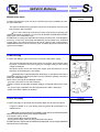
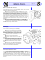
SERVICE MANUAL
Page: 1
COMINOX
The present document belongs to COMINOX. It can not be copied or sold to anybody without COMINOX informed approval.
Via G. Viganò, 7
20048 CARATE BRIANZA
Milano (Italy)
Phone: +39 0362.91.23.12
Fax: +39 0362.90.09.40
www.cominox.com
e-mail: [email protected]
SERVICE MANUAL
AUTOCLAVE
Sterilising
STERICLAVE 18/24
Document Code: SCG03824
Mod.
24 S
24 B
24 BHD
Mod.
18 S
18 B
18 BHD
FOREWORD
The present operating instructions ARE NOT integral to the unit. The instructions
are only to be supplied to qualified and specialised technicians liable to ordinary
service and unit repairing. Technicians or operators liable for the unit installations
are to be authorised in writing by COMINOX.
Any operator or technician is liable to read the operating instructions and strictly
comply with its instructions and information as COMINOX is not liable at all for any
damage to people or things or to the unit, should the operator not comply with the
hereby described general operating conditions.
Such instructions are confidential and the customer is liable not to disclose any
information. What is more such operating instructions and its annexes can not be
changed, tampered, modified, violated, copied or sold anybody without COMINOX
approval.
S
SERVICE MANUAL
INDEX
FOREWORD ....................................................................................................... 1
INDEX ................................................................................................................. 2
Reference numerical index ............................................................. 3
Reference alphabetical index ......................................................... 3
SIGNALLING ...................................................................................................... 5
Cooling Stop ................................................................................... 5
Check water quality ........................................................................ 6
Check automatic filling .................................................................... 6
Waste water maximum level ........................................................... 7
Open door or door not locked ......................................................... 7
Manual stop alarm .......................................................................... 8
Power missing ................................................................................ 8
Printer not ready ............................................................................. 8
ALARMS ............................................................................................................. 9
Insufficient water level .................................................................... 9
Poor water quality ......................................................................... 10
Chamber level alarm ..................................................................... 10
Triac alarm .................................................................................... 11
Insufficient steam .......................................................................... 11
Pressurisation alarm ..................................................................... 12
Over-temperature alarm ............................................................... 12
Insufficient vacuum alarm ............................................................. 13
Fractioned vacuum alarm ............................................................. 13
Level probe alarm ......................................................................... 13
Over-temperature sterilisation temperature band ......................... 14
Under-temperature sterilisation temperature band ....................... 14
Lost data alarm ............................................................................. 15
Alarm code list .............................................................................. 15
CONTROLS OR ADDITIONAL ADJUSTING ................................................... 16
Empty or not-well readable display ............................................... 16
Level probe control ....................................................................... 16
Door adjusting ............................................................................... 16
Water in the tank after the cycle ................................................... 17
Poor drying ................................................................................... 17
Pressure increasing too slowly ..................................................... 17
Vacuum Pump .............................................................................. 18
Water self drain and direct drain KIT (OPTIONAL) ....................... 18
The printer does not print .............................................................. 19
Printer KIT (OPTIONAL) ............................................................... 19
Water automatic drain does not work ........................................... 21
Steam loss from the safety valve .................................................. 21
DIAGRAMS AND WIRINGS ............................................................................. 22
Logic electronic motherboard ....................................................... 22
Logic motherboard electric wiring 33 ............................................ 23
Power electronic motherboard ...................................................... 24
Power motherboard electric wiring 34 .......................................... 25
Electric wiring 18S - B - BHD / 24S - B ......................................... 26
Electric wiring 24BHD ................................................................... 27
Hydraulic wiring 18S - B - BHD / 24S - B ...................................... 28
Hydraulic diagram 24 BHD ........................................................... 29
Page: 2
S
SERVICE MANUAL
Reference numerical index
03, power supply cable .................................................................................. 8, 16
05, metering funnel ............................................................................................... 9
06, access keys .............................................................................................. 5, 22
08, tray holder ....................................................................................................... 9
09, chamber ................................................................... 5, 9, 10, 11, 12, 14, 17
10, clean water tank ...................................................................9, 10, 18, 28, 29
11, waste water recovery tank .......................................................... 7, 22, 28, 29
12, safety valve ..................................................................................... 21, 28, 29
13, cut-out switch ........................................................................................... 8, 16
14, filler ............................................................................................. 9, 10, 28, 29
15, air sterilisation filter ......................................................................... 17, 28, 29
16, door ................................................................................... 5, 7, 9, 11, 13, 16
17, safety thermostat ............................................................................. 11, 26, 27
18, printer door .................................................................................................... 19
19, coil covering grid ............................................................................................. 9
20, drain filter ............................................................................................... 13, 17
21, chamber probe ......................................................................................... 9, 10
24, clean water drain tap .............................................................................. 28, 29
25, dirty water drain tap ........................................................................... 7, 28, 29
26, printer ....................................................................................................... 8, 19
29, water self drain ........................................................................... 6, 10, 18, 21
30, direct waste drain ..................................................................................... 7, 18
31, chamber seal ................................................................................... 11, 13, 16
32, fuses .....................................................................................8, 16, 19, 26, 27
33, logic motherboard .................................................................... 20, 22, 23, 24
34, power motherboard ............................................................ 10, 11, 19, 24, 25
35, water drain pump ........................................................ 10, 24, 26, 27, 28, 29
36, closing micro-switches ............................................................................. 7, 22
37, unlocking tool ................................................................................................ 11
38, transducer .......................................................................... 11, 14, 22, 28, 29
39, temperature probe ........................................................................... 11, 12, 14
40, inspection plugs ..................................................................................... 12, 14
41, vacuum pump .............................................................. 13, 18, 26, 27, 28, 29
42, fans ........................................................................................... 11, 13, 26, 27
43, level probes ................................................................................................... 16
46, water self charge pump ................................... 6, 18, 21, 24, 26, 27, 28, 29
Reference alphabetical index
A
access keys 06 ............................................................................................... 5, 22
air sterilisation filter 15 .......................................................................... 17, 28, 29
C
chamber 09 .................................................................... 5, 9, 10, 11, 12, 14, 17
chamber probe 21 .......................................................................................... 9, 10
chamber seal 31 .................................................................................... 11, 13, 16
clean water drain tap 24 ............................................................................... 28, 29
clean water tank 10 ....................................................................9, 10, 18, 28, 29
clean water thank 10 ........................................................................................... 22
closing micro-switches 36 .............................................................................. 7, 22
coil covering grid 19 .............................................................................................. 9
cut-out switch 13 ............................................................................................ 8, 16
Page: 3
S
SERVICE MANUAL
Page: 4
D
direct waste drain 30 ...................................................................................... 7,
dirty water drain tap 25 ............................................................................ 7, 28,
door 16 .................................................................................... 5, 7, 9, 11, 13,
drain filter 20 ................................................................................................ 13,
18
29
16
17
F
fans 42 ............................................................................................ 11, 13, 26, 27
filler 14 .............................................................................................. 9, 10, 28, 29
fuses 32 ......................................................................................8, 16, 19, 26, 27
I
inspection plugs 40 ...................................................................................... 12, 14
L
level probes 43 .................................................................................................... 16
logic motherboard 33 ..................................................................... 20, 22, 23, 24
M
metering funnel 05 ................................................................................................ 9
P
power motherboard 34 ............................................................. 10, 11, 19, 24, 25
power supply cable 03 ................................................................................... 8, 16
printer 26 ........................................................................................................ 8, 19
printer door 18 ..................................................................................................... 19
S
safety thermostat 17 .............................................................................. 11, 26, 27
safety valve 12 ...................................................................................... 21, 28, 29
T
temperature probe 39 ............................................................................ 11, 12, 14
transducer 38 ........................................................................... 11, 14, 22, 28, 29
tray holder 08 ........................................................................................................ 9
U
unlocking tool 37 ................................................................................................. 11
V
vacuum pump 41 ............................................................... 13, 18, 26, 27, 28, 29
W
waste water recovery tank 11 ........................................................... 7,
water drain pump 35 ......................................................... 10, 24, 26,
water self charge pump 46 .................................... 6, 18, 21, 24, 26,
water self drain 29 ............................................................................ 6,
22,
27,
27,
10,
28,
28,
28,
18,
29
29
29
21
S
SERVICE MANUAL
Page: 5
S
SIGNALLING
Signals and signalling are messages which in the majority of cases ask for a simple
correction or control operation by the user. Alarms ask for service or informs
about the presence of a possible failure.
When enabled, they are displayed on the display, followed by a sound running for 30
seconds. To reset the signalling or the alarm, it is necessary to use one of the
access keys 06 and then press the key STOP.
The “COOLING STOP” and “CHECK WATER QUALITY” signals are followed by a
sound and do not need any reset through the key STOP.
Signalling / Cause /
Remedy
Cooling Stop
It signals that the chamber 09 temperature is not suitable to start the unit up or to
keep the cycle running (refer back to chapters START-UP, FOLLOWING
STERILISATION CYCLES and VACUUM TEST).
The unit displays such a signalling in STAND-BY or after starting a cycle and the
unit is stopped during the pre-vacuum phase. Generally such a signalling is
affecting the unit operation when different operating cycles close to each other
are started, that is one after the other with no time for the unit chamber to cool
down.
Under such conditions, it is simply necessary to let the chamber cool down.
To speed up cooling, it would be advisable to open the unit door 16 ,
otherwise it would take a longer time for the unit to cool down. To open the door,
press the key STOP twice, with one of the two key in the socket and wait for a few
seconds until pressure inside the chamber decreases as to allow the unit door to be
opened.
When the door is closed, the operating cycle will be automatically repeated
when the admitted temperature is reached.
Once opened the door, it is necessary to recover the operating cycle and
start the cycle once more.
COOLING STOP
SERVICE MANUAL
Page: 6
Check water quality
S
CHECK WATER
QUALITY
Such a signalling is only present on any model fitted with a water demineralisation
unit (OPTIONAL). Under such conditions, the unit is fitted with a conductivity meter
on water coming from the demineralisation system.
Such a signalling is released during STAND-BY, only when the unit is fitted with
the optional demineralisation unit and the water self drain 29 is programmed, in
the B configuration from the water system (refer to the OPERATING AND
SERVICE INSTRUCTIONS, chapter CONNECTIONS) and set on the
switchboard: SELF-FILLING = 1. It signals that the water conductivity value,
inlet through the demineralisation external unit, overcame the optimum level but
it is still acceptable.
(B)
29
·
One or more operating cycles can be started on the autoclave but it is advisable
to follow instructions in the “INSUFFICIENT WATER QUALITY” alarm, as the triggering
of a second alarm will stop the unit.
ATTENTION: if the water conductivity increases, it means that mineral salts
presence increased too, water will NO LONGER be compliant.
Check automatic filling
CHECK AUTOMATIC
FILLING
Such a signalling is only present on unit models fitted with water self charge 29
(OPTIONAL) both fed from the mains or through an external tank.
Such a signalling is released in STAND-BY, only when the water self charge was
fitted and programmed (refer back to OPERATING AND SERVICE
INSTRUCTIONS, chapter CONNECTIONS).
If the (A) configuration is set, it is necessary to
fill or replace the distilled or demineralised water tank and
check that the difference in height between the unit and
the external tank accounts for or it is lower than 100 cm;
ATTENTION: The constant pump dry operation affects
its operating lasting time and dramatically reduces its
operating life.
Check that the loading pipe is not bent or clogged;
If the problem can not be solve, check that the
water self charge pump 46 is working.
If the (B) configuration is set, check the water
supply tap is opened and that the water supply pressure
is higher than the minimum pressure prescribed by the
manufacturer of the installed demineralisation system.
In both cases, it is necessary to check:
- that all connections are correctly connected;
- that no pipes are not fitted, leaking or clogged.
If the problem can not be solved, it possibly means
that the solenoid valve EV7 must be replaced.
(A)
29
46
(B)
EV7
29
SERVICE MANUAL
Waste water maximum level
Page: 7
S
WASTE WATER
MAXIMUM LEVEL
It signals that the waste water recovery tank 11 is full and must be emptied.
The signal is released at the cycle start-up.
Empty the tank (refer back to OPERATING AND SERVICE INSTRUCTIONS,
chapter INSTALLATION, description TANK SELF DRAIN).
ATTENTION: the liquid temperature can reach 80°C and the liquid can be infected.
Dispose the liquid according to the regulations in force in each single country.
If the direct waste drain 30 is programmed, check the correct connection
and that the pipe is not bent or clogged.
If, after emptying the tank, the signal is still on, check:
- level probe as it could have been dirtied by algae or scales depending on water
stagnating in the tank and leading to a false signal (refer back to the LEVEL PROBE
CHECK);
- the probe and unit grounding, as the unit operating depends on the correct grounding
connection.
During long downtimes, completely empty the tanks and clean with a cleaning solution
(70% water and 30% alcohol). Such a solution should NOT at all be used to start
a cycle, therefore rinse before any further operation.
The waste water recovery tank can be filled without disassembling any unit part,
simply connecting the dirty water drain tap 25 and loading fluid under a light pressure,
for example keeping the fluid container higher than the unit. It is possible to fill the
tank removing the panelling as well as the upward pipes and hoses.
Open door or door not locked
It signals that the door 16 was not correctly closed.
The signal is released when you try to start a cycle and the handle is not completely blocked. Under such conditions, the unit can not start.
Well close the door before starting a cycle up.
If the signal can not be stopped, even though the door is well closed, it
means that one of the closing micro-switches 36 is not correctly excited or it is broken, therefore check that:
- the micro-switches do not exhibit any loosen clamping nuts;
- the bar is not bent, out of its seat, or loosen;
- the micro-switch contacts are live, check with a tester;
- there is no clogging or dirt built-up next to the bar-micro-switch contact
- connecting cables between the door and the unit are operating and well connected.
ATTENTION: to check which of the two micro-switches is generating the signal,
check:
- if the sound alarm immediately starts when the door is closed, it means that the
micro-switch which is not operating is the micro-switch on the bottom inside the unit;
- if the sound alarm only starts after a few seconds, with a short delay if compared to the door closing, it means that the micro-switch which is not operating is the
micro-switch inside the door itself.
It is possible to access the internal micro-switch, by removing the unit from any
furnishing unit as well as it covering.
It is possible to access the door micro-switch as follows:
- remove the 4 bolts external to the door 16 disk;
- remove the handle;
- remove the plastic part;
- check that the stud on the reel head correctly pushes and presses the micro-switch
bar and it is not misaligned.
(Mod. 18)
25
(Mod. 24)
OPEN DOOR OR
DOOR NOT LOCKED
SERVICE MANUAL
Manual stop alarm
Page: 8
S
MANUAL STOP
ALARM
It signals that during the cycle start-up, the STOP key was pressed before the natural cycle conclusion.
The signal is released during operation and the unit is stopped to inform the user
that the load is NOT STERILE.
As it is not a failure but a forced cycle stop, released by the operator, NO
specific intervention is required. It is necessary to consider the load NON STERILE
and re-start a new sterilisation cycle.
ATTENTION: It is always not advisable to manually STOP the unit, if not absolutely
necessary. In fact if the unit already concluded the pressurisation or the fractioned
vacuum phase, the internal material can be wet or extremely wet and therefore it
could be difficult for the unit to re-start the cycle. Therefore dry well the materials and
replace the envelopes.
Power missing
POWER MISSING
......................................
It signals that during a cycle, the unit was cut from the main power supply.
The signal is released when the power supply is recovered. On the display, when
the unit is connected to the power supply, the message relating to the missing
voltage is displayed.
Should the unit be cut from the main power supply when the alarms are on, the
last alarm will be displayed on the display.
According to the signal displayed on the display, it is possible to come to the
conclusion whether the unit, despite power missing, entirely or partially came to the
end of the sterilisation cycle.
Power can be missing for the following reasons:
- pressure error at the cut-out switch 13 level
- power is entirely missing from the power supply or a magneto-thermal fuse is broken;
- the power supply cable 03 is not correctly fitted or the cable is damaged;
- power fuses 32 are broken or oxidized.
Printer not ready
It signals that paper is missing or that the printer door was not correctly closed.
A signal is release on a cycle starting when the printer 26 (OPTIONAL) is installed and set.
Recover the correct operating conditions (refer to back to OPERATING AND
SERVICE INSTRUCTIONS, to the chapter PRINTER).
If the signal is still on, check
- that the printer door is perfectly closed;
- that the power supply cable are duly connected to the printer
ATTENTION: for a more technical and detailed explanation, refer to chapter PRINTER
INSTALLATION (OPTIONAL)
PRINTER
NOT READY
SERVICE MANUAL
Page: 9
S
ALARMS
Differently from any signal, alarm STOP the unit, therefore once solved the problem
which provoked the alarm and reset the alarm itself pressing the key STOP, it is
necessary to switch the unit ON once more and the start a new cycle.
The load in the autoclave during the cycle interrupted by the alarm is to be considered NON STERILE.
Alarm / Cause /
Remedy
Insufficient water level
INSUFFICIENT
WATER LEVEL
It informs that distilled or demineralised water is missing in the clean water tank 10.
When water is missing in the tank, the led MIN on the keyboard is switched on thus
triggering the alarm.
If the alarm is triggered when the cycle is started up, fill the tank or the
tank used for the water self filling (refer back the OPERATING AND SERVICE INSTRUCTIONS, chapter SETTING, SELF CHARGE and CLEAN WATER TANK)
The tank filling, with no self charge can be enforced as follows. Simply loosen and
remove the filler 14 cover and fit in the supplied metering funnel 05 (only use suitable distilled or demineralised water).
If a filling is enforced when the unit is on or in STAND-BY, the MAX and MIN le don
the control board allow to check the water level. A sound signal lasting for 1 second
follows the LED MAX switching on to specify that the tank is full. If no sound signal is
heard, excess water comes out from the filler.
The tank filling, with an automatic cycle (OPTIONAL) can be enforced as follows. It
simply arrives when water is missing,. It is necessary to check that there is enough
water in the external filling tank. Should water be missing, on the display the signal
CHECK SELF CHARGE will be displayed, and therefore follow instructions referring
to the signalling itself.
If the alarm was displayed during the cycle, fill the tank and move forward according to the instructions given in the case of “INSUFFICIENT STEAM”.
ATTENTION: the unit doses water in the boiler, to generate steam, through a pump,
until water touches the chamber probe 21. If during filling water is not enough, it
means that water or steam is coming out from the valves, from the chamber or from
the pipes. Under such conditions, water leaks and builds up under the unit.
Should no cause be detected, it is necessary to check the chamber probe as possibly it does no longer read the water level inside the chamber.
To check the probe correct operation, it is necessary:
- to open the door 16 and remove the entire chamber 09 load;
- to remove the tray holder 08;
- to remove the coil covering grid 19 loosening the relating screw;
- reassemble follow the reversed order, that is horizontally turn the grid with its seal.
- switch the unit in STAND-BY;
- press at the keys STOP and at the same time, as to manually start the loading
pump, which should be stopped within a few seconds, that is when the demanded
water is let in and touches the probe.
The probe could be dirty or the power supply cable or the grounding cable be failing.
Under extreme conditions, when a special cycle was launched, with 3
fractioned vacuum peaks and with a rather heavy porous load, the minimum forecast level could be no longer enough. Try to reduce the load or simply use 2 fractioned
vacuum peaks.
Another cause which can generate a similar alarm can depend on the electronic board. In the case of failure, replace the board.
09
16
21
SERVICE MANUAL
Page: 10
Poor water quality
S
POOR
WATER QUALITY
Such an alarm is present only on unit where a water demineralisation unit is fitted
(OPTIONAL). Under such conditions, the unit is fitted with a conductivity meter of
the water coming from the demineralisation unit.
Under such conditions, the unit signals that the water conductivity level overcame
an acceptable level and stops the automatic filling.
(B)
29
The alarm is released when the cycle is started (refer back to the OPERATING
AND SERVICE INSTRUCTIONS, chapter SIGNALLING, CHECK WATER QUALITY) only when the demineralisation unit is fitted and the water self drain 29 cycle
as programmed in the B configuration to the water main supply system (refer
back to the OPERATING AND SERVICE INSTRUCTIONS, chapter CONNECTIONS) and set on the control panel SELF FILLING = 1.
It signals that the water conductivity value, filled through the external demineralisation unit, is NO LONGER acceptable. Before such an alarm, the message
CHECK WATER QUALITY was already displayed on the display.
Change the self filling cartridge used for the demineralisation of water from
the mains water supply, in compliance with the manufacturer’s instructions. It is advisable, once replaced the cartridges, to rinse the clean water tank 10.
Should it not be possible to start the unit, once replaced the cartridge in the
water demineralisation unit, it is possible to re-start the unit changing the SELF FILLING programming to 1 and manually filling the tank through the filler 14. Under such
conditions, water is not controlled and therefore check its features beforehand.
14
09
21
14
21
(Mod. 18)
09
(Mod. 24)
Chamber level alarm
CHAMBER LEVEL
ALARM
It informs that the necessary time was overcome to recover the correct water level
within the chamber 09.
The alarm is displayed when the chamber probe 21 does not read within the
allocated correct time the presence of water within the chamber.
Check once more the machine position (refer back to OPERATING AND
SERVICE INSTRUCTIONS, chapter INSTALLATION ).
If the problem can not be solved, check that:
- The water self charge pump 35 and the solenoid valve EV1 manage to pump water
inside the chamber 09 ;
- EV1 solenoid valve, whose reel could be failing;
- The water drain pump 35
- Fuse F3 on the power motherboard 34
- What specified in the case of POOR WATER LEVEL
35
EV1
SERVICE MANUAL
TRIAC alarm
Page: 11
S
TRIAC
ALARM
Such an alarm informs about the safety thermostat operation 17.
The alarm is displayed on the unit when the circuit on the coils IS NOT closed.
The following controls and checks are to be enforced in the specified order:
Reset the safety thermostat 17, removing its cap and pressing the pin under
it. The thermostat can only be reset if the boiler cooled down. To speed up cooling
times, open the boiler door, which will be blocked. The door 16 can only be opened
by means of the unlocking tool 37 (any service centre is supplied a suitable tool) in
the special hole on the right under the door. The unlocking tool 37 must reach the
door opening. Lower the door handle, with no stress. Remove the unlocking tool 37
and completely lower the handle and open the door.
reset the alarm pressing the key STOP when one of the two keys is fitted in the
socket;
Check the correct fans 42 operation;
Check that the unit is correctly and enough ventilated;
Check coils, both the internal and the external coil. It is simply enough to
check their continuity by means of a tester, without minding about the power value;
Check the TRIAC on the power motherboard 34.
Insufficient steam
Such an alarm informs that steam or over-heated steam is coming out from the
chamber 09.
The alarm is released during the cycle, when at 114° the unit does not reach a
suitable pressure to enforce a cycle. Pressure is detected by the transducer 38
while temperature by the temperature probe 39.
Check the efficiency and cleaning of the
chamber seal 31 as well as the door 16 internal disk,
the seal is fitted to. Possibly, if damaged, replace it .
Should steam leak be detected, it is necessary to
adjust the door closing following what specified in
chapter ADJUSTING DOOR:
Check once more the unit bending (refer
back to OPERATING INSTRUCTIONS, chapter INSTALLATION)
Check that the unit total weight is not overcome (refer back to OPERATING INSTRUCTIONS,
chamber OPERATION)
If the alarm is still on, notwithstanding the
above-mentioned checks, it is necessary to check
the drain solenoid valve EV2 (refer to the diagrams).
Being connected under the drain, it is connected to
the filter inside the chamber and it is the first solenoid valve to come in contact with steam, therefore
it is the solenoid valve asking for the more consistent service and to be replaced in time.
INSUFFICIENT
STEAM
SERVICE MANUAL
Page: 12
S
Replace it when overcoming the fixed schedule on the PROGRAMMED SERVICE
TABLE (refer back to the OPERATING and SERVICE INSTRUCTIONS, chapter
SERVICE). Any possible cleaning is to be enforced as follows:
- remove the solenoid valve, minding the specific part sequence, to re-assemble it
when required (A)
- clean the valve core (B) as to allow the tight seal to correctly slide inside, pushed by
the small spring (C). Should the seal be deformed, replaced it.
In the case the steam is still leaking, put the unit under pressure and empirically
check the specific part where the leaking comes from, as follows:
- once check the unit door, perfectly close it;
- remove the unit cover;
- excite, by means of the external power supply cable at 220 Volt, the solenoid valve
reel EV2 (refer back to the wiring), as it is normally opened NA;
- remove one of the inspection plugs 40 and fit to the compressor (min. 2 bar/max 3
bar);
- let compressed air in and empirically check the leaking and loss.
Check the pressure/temperature alignment (refer back to STERILISATION
TEMPERATURE BAND)
Carry out a VACUUM TEST to check the presence of possible pressure
losses.
Pressurisation alarm
PRESSURISATION
ALARM
Such an alarm informs only about a small steam loss, which can be solve enforcing
one of the remedy described in the case of INSUFFICIENT STEAM.
If the alarm can not be solved, it could depend on a failure of the heating
circuit. Check that during pressurisation or fractioned vacuum phases, the chamber
internal coil is correctly fed through the contact N.A ce. CT2 (refer to diagrams).
Over-temperature alarm
The alarm informs that temperature inside the
chamber 09 overcame 150°C.
The alarm is released during the cycle, when
temperature reached 150°C.
Check that on the temperature probe 39
no cable is disconnected, wore or it is failed;
Check the correct load positioning, which
should be correctly fitted on the supports;
Check the water dosing in the boiler, as
in the case of the insufficient water level alarm.
OVER-TEMPERATURE
ALARM
SERVICE MANUAL
Insufficient vacuum alarm
Page: 13
S
INSUFFICIENT
VACUUM ALARM
The alarm signals that during the pre-vacuum phase, pressure did not reach the
correct set value.
The alarm is displayed during a cycle, in the pre-vacuum phase, when pressure did not reached the correct programmed value.
Check the efficiency and cleaning of the
chamber seal 31 and on the door 16 internal disk, which
it is fitted against and possibly, if damaged, replace it.
Check the vacuum pump 41 (refer to CHECKS
AND ADDITIONAL ADJUSTING – Vacuum Pump);
Check the correct positioning of the drain filter
20 and its cleaning;
Carry out a VACUUM TEST to check the possible presence of air leak
Check the correct operation of the two fans 42;
Check that the unit is correctly ventilated and
ventilated enough.
Fractioned vacuum alarm
FRACTIONED VACUUM
ALARM
The alarm signals that depression is missing inside the chamber 09.
The alarm is released during the cycle, during a vacuum peak, in the vacuum
pulse phase, pressure did not reached the correct programmed value.
Follow the instructions specified in the case of the alarm “INSUFFICIENT
VACUUM”.
Check that the total maximum load weight was not overcome and that the
materials which the load consists of are compatible with the selected cycle (refer
back to OPERATING AND SERVICE INSTRUCTIONS, chapter OPERATION), for
example: never mix fabrics with solid loads.
Check the correct operation of the two fans 42;
Check the unit is correctly ventilated (mainly in the case of the built-in unit);
Check that the vacuum pump 41 is correctly fed and that it correctly works.
Theoretically a pump failure is detected far before such an alarm, during the prevacuum phase.
Level probe alarm
Such an alarm indicates that the level probes are not correctly operated. For example: the maximum level probe detects the present of liquid and the minimum level
probes as well as the empty tank probes are to detect the same presence of liquid.
The alarm is released when a cycle is being started.
Empty, clean and fill the water tanks. The operation is to be carried out when
the unit is not being operated.
Check the level probes
Check the water quality: the correct and demanded conductivity value (at
20°C) ≤ 15 µS/cm. An excessively pure water beside being corrosive, as it tends to
remove salts from minerals, can not be detected by the probes. More precisely
avoid using Bi-distilled water.
LEVEL PROBE
ALARM
SERVICE MANUAL
Over-temperature sterilisation temperature band
Under-temperature sterilisation temperature band
Both alarms signal that there is no longer compliance with the sterilisation temperature band. The sterilisation temperature band (tolerance) is defined by the regulations in force (prEN 13060) and it implies that during the sterilisation cycle the set
value difference (for example 134°C) accounts between -0°C and +4°C. Therefore
under such conditions, temperature will never be lower than 134°C and could never
be higher than 138°C.
The unit displays one of the two alarms during the sterilisation phase, when checking the two temperature values, one is directly detected and the other one comes
from the saturated steam curve under pressure, even when one of the two values
is not compliant with the above-mentioned tolerance.
ATTENTION: the alarm could depend on the fact the both temperature and pressure
values are not correct. In any case it acts simply adjusting temperature.
If the signalled alarm is the UNDER-TEMPERATURE alarm, check that the
maximum total load weight is not overcame (refer back to the OPERATING and
SERVICE INSTRUCTIONS, chapter OPERATION).
Check temperature calibration, through the special SIT certified tools, duly validated, as to compare temperature values to pressure values detected by the unit
probes with values detected by any external tool or device.
To carry out a pressure control and the temperature adjusting inside the chamber 09 follow the hereby described
procedure:
- remove the unit from the furnishing unit, if it is a built-in
unit, and remove the covering;
- loosen and remove the inspection plugs 40 on the two
ends, on the upper portion of the chamber;
- fit in the measuring tool probes checking their tightness
and that they are correctly positioned, that is check that
probes do not touch the chamber wall or the internal coil.
It is advisable to fit the temperature probe backward at
the end of the temperature probe 39. As an alternative, it
is possible to use wireless probes to be fitted inside the
sterilisation chamber and do not ask for any assembly
- test during an operating cycle and check values. It is
advisable to carry out such adjusting during a HOLLOW POROUS load cycle, at
134°C, as pressure during such a cycle reaches the lowest values;
- adjust temperature according to pressure in compliance with the saturated steam
curve through the RV3 trimmer (refer back to the DIAGRAMS and WIRINGS chapter, logic electronic motherboard). Set temperature can be increased turning the
trimmer clockwise and can be reduced turning the trimmer counter clockwise. A
complete trimmer revolution corresponds to about 1°C change.
As far as the transducer 38 alignment is concerned with the external calibrated tool,
in case values read by the unit are higher that 60 mbar or lower than 80 mbar, simply
replace the transducer.
ATTENTION: Temperature is to be adjusted a few degree before entering the sterilisation phase.
If the alarm can not be stopped, notwithstanding adjusting, its different
causes can mainly be:
- Sudden loss or leakage from a valve or a tube failure;
- Broken temperature sensor;
- Broke pressure transducer 38;
- Failing electronic motherboard.
Page: 14
S
OVER-TEMPERATURE
STERILISATION TEMP. STER.
UNDER-TEMPERATURE
STERILISATION TEMP. STER.
SERVICE MANUAL
Lost data alarm
Such an alarm signals a data loss from the RAM memory (refer back to DIAGRAMS
and WIRINGS, logic electronic motherboard).
One of the main reasons the data loss depends on is the wrong assembly of
the RAM or EPROM memories
Check that some pins on the memory is not broken, folded or out of its
correct seat
A different cause can depend on a power supply rise or on high electromagnetic interferences, screen or isolate their source, if possible
Alarm code list
Alarm code type
00
TRIAC ALARM
01
OVER-TEMPERATURE ALARM
02
HEATING ALARM
03
INSUFFICIENT STEAM
04
INSUFFICIENT WATER LEVEL
05
free
06
WASTE WATER MAXIMUM LEVEL
07
DOOR OPEN OR DOOR NOT LOCKED
08
CHAMBER LEVEL ALARM
09
MANUAL STOP
10
INSUFFICIENT VACUUM
11
FRACTIONED VACUUM ALARM
12
free
13
LEVEL PROBE ALARM
14
PRESSURISATION ALARM
15
OVER-TEMPERATURE STERILISATION BAND ALARM
16
UNDER-TEMPERATURE STERILISATION BAND ALARM
17
PRINTER NOT READY
18
POWER MISSING
Page: 15
S
LOST DATA
ALARM
SERVICE MANUAL
Page: 16
S
CONTROLS OR ADDITIONAL ADJUSTING
.......................................
Empty or not-well readable display
If no information is displayed on the display and/or any displayed information is not
well visible, mainly check what follows:
Check power at the socket level, the correct fitting of the power supply cable
03 into the supply socket and its connection to the unit.
Check fuses 32 and that the cut-out switch 13 is duly pressed in its correct
position “I”.
If the display is not well readable where the operator stands, change the
reading position.
If after such a change, the display is more readable, adjust the contract by
means of the trimmer RV1 starting from the position it is best to be read (refer back
to chapter DIAGRAMS and WIRINGS, logic electronic motherboard).
Level probe control
The level probes 43 of both tanks are simple metal bars fitted into the unit to be
controlled and duly insulated from the unit itself. The probe circuit is closed then the
unit is filled with fluid.
It is possible that the presence of algae or clogging lead to an electric continuity
between tank metal and level probe bar, therefore reading the presence of liquid
within the tank when the tank is empty.
Therefore, if after emptying the tank, any alarm or signalling is still on, it is
necessary to disassemble and accurately clean the probes, following the hereby
described procedure:
- Remove the panelling and the faston (A) on the probe faston;
- Loosen by means of a wrench ch 13 the probe holder (B) and remove the probe
bar;
- remove the ogive (C) in teflon; generally such an ogive changes its shape to provide for the correct tightness with the probe holder pressure, therefore it easily takes
the shape of the threaded seat. To remove the ogive, unscrew the ogive with a
screwdriver, which is then to be replaced;
- accurately clean any probe part (C) and the bar and fit back the assembly once
more.
Door adjusting
If after checking and cleaning the chamber seal 31 and the door 16 disk, it is
fitted on, any leakage or loss is reported, it is necessary to adjust the door closing as
follows:
- switch the unit off and wait for its cooling, then open the door;
- by means of a wrench ch5 unscrew the screw inside the hole
on the left side of the door. When the screw is loosen, the door
disk freely rotates;
- turn the disk counter clockwise for about + of a revolution;
- tighten the hexagonal screw ch5 fixing it;
- when closing the door, a higher resistance is to be felt;
- try a new cycle and possibly repeat the operation
ATTENTION: do not excessively unscrew the door disk as an excessive
pressure could lead to a seal shape deformation.
SERVICE MANUAL
Water in the tank after the cycle
If at the end of the cycle, there is still water inside the chamber 09 it is necessary
to follow the hereby described procedure:
Check that the selected cycle includes drying, otherwise it is normal that there is still some water or moist inside the chamber. If the material
is not wrapped and it is removed from the chamber just after sterilisation, it
will be noted that temperature itself allows to rapidly dry it, even when the
set cycle does not imply any drying, while if materials are remove after a
specific amount of time and after a cycle with no drying, it will be necessary
to dry materials in a different way. Therefore if material is not removed
immediately after the sterilisation cycle, it is necessary to set a cycle including drying;
Check the cleaning and correct positioning of the drain filter 20
(refer back to the OPERATING INSTRUCTIONS, chapter SERVICING);
Check once more the unit bending (refer back to the OPERATING
INSTRUCTIONS, chapter INSTALLATION).
Poor drying
If at the end of the cycle, drying is not satisfactory.
Check that the sterilisation cycle including drying was selected and that the selected cycle is correct
for the specific material to be sterilised (refer back to the
OPERATING INSTRUCTIONS, chapter OPERATION);
Check that the total maximum load is not overcome;
Check that correct load preparation;
Check the cleaning and correct drain filter 20
positioning;
Check the air sterilisation filter 15 as described
in the charter PRESSURE INCREASING TOO SLOWLY;
Check once more the unit bending (refer back to
the OPERATING INSTRUCTIONS, chapter INSTALLATION).
Check that the valve EV5 (refer back to the wiring) opens during drying. Such a valve is normally closed,
it allows to let heated air picks in during drying.
Pressure increasing too slowly
If the pressure, at the end of the cycle, increases too slowly, it is necessary:
To check the air sterilising filter 15 and possibly replace it. Remind that such
a filter as many other parts lasts only for a specific time period (refer back to the
OPERATING INSTRUCTIONS , chapter SCHEDULE SERVICING). It is NOT possible to carry out any sterilisation cycle when the filter is not fit in or when the filter is
damaged or holed. Under such conditions sterilisation is contaminated with environmental air.
Page: 17
S
SERVICE MANUAL
Page: 18
S
Vacuum Pump
The vacuum pump can be checked by simply cleaning it or replacing its seals, supplied in kit.
More precisely in the case of the vacuum pump 41 A, it is necessary to check
what follows:
Remove the pump, attentively checking the part position;
Check that the membranes A are not damaged and clean them;
Check the valve blades B, and when assembling them back, check their
positioning and direction, as blades are in harmonic steel, slightly bent and the plate
exhibits rounded corners on one single side.
More precisely in the case of the vacuum pump 41 B, it is necessary to check
what follows:
Remove the pump, attentively checking the part position;
Check that the membranes C, small valves D or OR rings are not damaged
and clean them or if nothing can be done replace them;
Membrane C is to be fitted to the pump piston, turning it clockwise. To avoid
any movement, it is advisable to use a braking liquid or paste.
When assembling everything back, pay attention to the correct part direction, as a wrong direction will lead to a wrong operation. Outlet F is to be fitted after
screwing membrane C, but it is necessary to slide the membrane C lips above the
ring inside the outlet, by means of a screwdriver.
ATTENTION: if the pump is to be replaced, remove the rubber plugs E.
B
A
41A
Water self drain and direct drain KIT (OPTIONAL)
Such a KIT is to be fitted after installing the unit and it includes both the water self drain
29 and direct waste drain 30. Parts are the same on both models, with the exception
of the tube length and their positioning.
Remove the unit from its packaging; position on the correct side and remove
the cover;
Remove plugs (T) on the unit lower portion (right side);
Assemble the plastic joint on the bigger hole, which is used as a drain;
Assemble joints and rubber-holder on the smaller hole to be used for the
water self drain 29, direct the external rubber-holder to the drain;
Fit the water self charge pump 46 correctly blocking it on its support. The
pump to be used for model 18 is fitted on the base, while the pump used on model
24 is fitted on the clean water tank 10;
Finally fit the offsets (Y) and the connecting pipes.
(Mod. 18)
46
(Mod. 24)
46
SERVICE MANUAL
Fit the external filling and drain pipes; the filling pipe in the terminal portion is
custom cut to avoid the sucker effect when on the tank bottom; the drain pipe is fitted
with a male rapid connecting joint.
Check the unit and its tightness;
Check the unit operation and then close and fit back in the unit.
The printer does not print
Some units are not fitted with a printer 26 (OPTIONAL), therefore check that the unit
is fitted with a printer. Even though the printer not is available on any model, on each
model it is possible to set the printer. As a consequence, programming the printer on
a unit which is not fitted with a printer, the unit will release the signal: PRINTER NOT
READY.
Checking the presence of the printer, it is necessary:
To check that “PRINTER=1” programming information (refer back to the
OPERATING INSTRUCTIONS chapter OPERATION, on the menu SETTINGS),
which allows to program the printer;
Check the printer door 18 closing as well as the perfect closing of the internal door holding the paper roll;
Check that there is enough paper and that the paper roll is correctly fitted;
ATTENTION: Never pull paper to slide or to allow it come out, as possibly the internal door will be opened or paper will be removed and the roll turned out of position.
To have paper coming out from the door, in STAND-BY press the arrow key
on
the control board. When
pressing the arrow key, paper is moved out from the door;
Check fuses 32 and fuse F3 on the power motherboard 34 as well as connections, more precisely the flat between the motherboard and the printer (refer
back to chapter OPTIONAL PRINTER INSTALLATION);
Check by means of a tester that at the printer motherboard entrance there is
enough power supply (230 Volts) as well as its outlet (12 Volts).
Printer KIT (OPTIONAL)
As far as the printer 26 assembly is concerned (OPTIONAL), the printer is only to
be fit after buying the unit. A KIT is supplied. It is possible to fit all the different unit
parts following the hereby described procedure:
ATTENTION: as the procedure is not tight, please, when not following it, comply with
the correct sequence and the part removal as to recover the correct unit operating
conditions.
Remove the unit from any furnishing unit and place on a consistent surface,
remove its cover;
Loosen the two screws fitting the power motherboard 34 and move it to the
side without removing any cabling, as to access the control panel screws (P);
Remove the control panel completely loosening the 2 upper screws and the
lower screw, possibly mark down their correct position (refer to diagram);
Remove the flange (R) putting the 4 fitting screws aside, as they will be later
used to fit the printer support;
Separately pre-assemble the unit
- remove the spacer (S) on the printer support (H) fitting it on the threaded
portion by means of the supplied nut;
- fit the printer support (H) on the printer itself, through 3 screws;
- pressure fit the printer board (F) on the spacer (S) in the central spacer hole.
Direct the board with all its parts to the printer, as to immediately fit the demanded
cabling of the upper flop and the connector coming out from the printer;
- fit the printer internal cable connector (L) on the board; the connecter on the
opposite side is to be fitted to the logic motherboard;
- fit the printer feeing cable on the board (M) with cables directed as specified
(frontally facing the terminal clamp in 3 positions, the correct sequence from left to
Page: 19
S
SERVICE MANUAL
right must be 1°) black cable, 2°) red cable, 3°) bridge with clamp 2). The connector
on the opposite side is to be fitted to the printer power board;
- Fit the pre-assembled group on the control panel (P). To correctly fit the
group on its seat, it is necessary to open the printer and fit it in the upper portion,
where the seat is wider. Fit by means of the 4 screws which had been previously
removed and fit the flange (R) back. The group is not perfectly tight and therefore it
is necessary to manually align it, at a specific distance from the right wall, where
there is the motor, as the central motor shaft MUST NOT touch the side walls.
Fit the printer motherboard (G) on the unit where to fit the printer. There are
4 available fitting holes, but only 2 will be used, the 2 diagonally opposing holes,
according to the unit model. The printer power board (G), to be correctly fitted, it is to
be directed with all its parts inside the unit. The two available connectors, the 2 PIN
connector is to be fitted to the upper portion and the 4 PIN connector to the lower
portion.
On the 2 PIN connector, connect the connector (T) of the pre-assembled cable
on the unit cabling. Generally connector (T) on the unit is isolated with rubber or tape
which is to be remove.
Fit back the control panel (P) with all the pre-assembled parts, on the unit,
tightening by means of the 3 previously removed screws;
Fit the power board 34 back in its correct position and tighten the fitting
screws
Connect the printer power cable (M) to the printer feeder board (G);
Connect the printer internal cable connector (L) to the CN7 connector to the
logic motherboard 33;
Check the operation and close, finally restart the unit.
Page: 20
S
SERVICE MANUAL
Water automatic drain does not work
If the water self drain 29 (OPTIONAL) does not perfectly
work, it is necessary to follow the hereby described procedure:
As not all the models are fitted with an automatic
drain, check that such a function is available on the existing
unit;
Check the programming information “SELF-FILLING=1” on the SETTING menu (refer to chapter OPERATION);
If configuration A is installed and set, from an external tank, check that there is enough water in the tank. If
there is enough water by the alarm “CHECK SELF-FILLING” is not, check that the suction pipe is correctly positioned up to the tank bottom. Check that the tube is not
bent, check that the height difference between the autoclave
and the tank bottom is no more than 1 meter (refer back to
CONNECTION, chapter INSTALLATION); check the
water self charge pump 46 operation.
In some cases, if the water self charge pump 46 is
dry used for a long time period, it can loose some of its
performance and therefore it does no longer manage to
prime or charge water within the demanded short time periods, therefore replace it;
If configuration B is installed and set, from the mains
water supply, check that the mains water tap is opened. If
the tap is opened and the alarm “CHECK SELF-FILLING” is
on, check that there is enough water downstream the assembled demineralisation system; check the EV7 solenoid
valve at its inlet;
Check fuse F3 on the power electronic motherboard.
Such a fuse protects any load and possibly replace it.
Page: 21
S
(A)
29
46
(B)
29
EV7
Steam loss from the safety valve
A steam loss from the safety valve 12 can depend on what follows:
If the autoclave was installed in a specific place where altitude is higher than
1500 meters on the sea level, a suitable safety valve is to be fitted (refer back to the
OPERATING INSTRUCTIONS, chapter FEATURES)
If the altitude is lower than 1500 on the sae level and/or the problem can not
be solved, check the valve efficiency and then replace it.
SERVICE MANUAL
Page: 22
DIAGRAMS AND WIRINGS
Logic electronic motherboard
The logic motherboard 33 is a low tension motherboard, the same on each unit. It is
supplied with no memory: EPROM and RAM, as it is necessary to use the customer
memories. On the EPROM body, holding the programme, the software issue is specified (for example 1.17), which is also to be specified in the part specification when it
is necessary to be replaced. Both memories are to be assembled in compliance with
the available set position, which defines its specific direction too (refer back to the
Figure).
The installation is to be carried out when the unit is not being operated. Its
wrong assembly can lead to the total date loss (refer back to the loss data alarm).
CN1
CN2-CN3
CN5
CN6
CN7
CN8
CN9
CN10
CN11
M1
RV3
RV1
Connection cable to the display;
Connection cable to the keyboard;
Connection cable to the power supplier;
Connection cable to the pressure transducer 38;
Connection cable to the printer (OPTIONAL);
Connection cable to the serial interface;
Connection cable to the level probes;
A - Alarm level of the clean water thank 10 alarm empty
B - Minimum level (LED min switches on)
C - Maximum level (LED max switched on)
D - Maximum level of the waste water recovery tank 11;
E - Chamber level
Connection cable to the access keys 06;
Connection cable to the closing micro-switches 36;
Connection terminals to the chamber temperature probe PT 1000;
Temperature adjusting trimmer (refer back to charter Sterilisation temperature band...);
Display adjusting trimmer (refer back to charter EMPTY DISPLAY or
DISPLAY NOT WELL READABLE)
S
SERVICE MANUAL
Logic motherboard electric wiring 33
Page: 23
S
SERVICE MANUAL
Page: 24
Power electronic motherboard
The power electronic motherboard 34 is the same on any unit model.
ON-OFF
F1
F2
F3
CN4
CN5
Remote control switch and cut-out switch
Fuse to protect the power motherboard supply
(T250 Volts delayed 250 mA);
Fuse to protect the transformer, additional circuit
(T250 Volts delayed 630 mA);
Fuse to protect any load (T250 Volts delayed 13.5 A);
CN1 TRIAC connector(refer back to the electric wiring as far as the
coil driving contactor connection is concerned);
Load connector, and more precisely:
A – suitable for the EV1 solenoid valve and for the
water drain pump 35;
B – suitable for the EV2 solenoid valve relating to the water drain
and in parallel CT2 contactor reel (refer back to the electric wiring);
C – suitable for the drying EV5 solenoid valve;
D – suitable for the door lock/opening solenoid valve;
E - suitable for the water self charge pump 46 (configuration A)
F – suitable for the following solenoid valves:
EV6 and EV3 vacuum pump, connected in parallel
Load connector from the logic motherboard 33 and
the power motherboard 34.
46
EV7
S
SERVICE MANUAL
Power motherboard electric wiring 34
Page: 25
S
SERVICE MANUAL
Page: 26
S
Electric wiring 18S - B - BHD / 24S - B
- EV…
-B
- CT1
- CT2
-F
- FU
- ET
- IB
solenoid valves
door blocking coil
power contactor
resistance piloting contactor
anti-noise filter
fuses 32
fans 42
cut-out switch 0-1
- P1
- P2
- PR
- PV
- RA
- RI
-T
water drain pump 35
water self charge pump 46 (configuration A)
Solenoid valve EV7 (configuration B)
safety pressure switch
vacuum pump 41
drying coil
inlet coil
safety thermostat 17
SERVICE MANUAL
Page: 27
S
Electric wiring 24BHD
- EV…
-B
- CT1
- CT2
-F
- FU
- ET
- IB
solenoid valves
door blocking coil
power contactor
resistance piloting contactor
anti-noise filter
fuses 32
fans 42
cut-out switch 0-1
- P1
- P2
- PR
- PV
- RA
- RI
-T
water drain pump 35
water self charge pump 46 (configuration A)
Solenoid valve EV7 (configuration B)
safety pressure switch
vacuum pump 41
drying coil
inlet coil
safety thermostat 17
SERVICE MANUAL
Page: 28
Hydraulic wiring 18S - B - BHD / 24S - B
- EV…
-B
-F
- P1
- P2
- PR
- PV
- RC
solenoid valves
door blocking coil
air sterilisation filter 15
water drain pump 35
water self charge pump 46 (config. A)
Solenoid valve EV7 (config. B)
safety pressure switch
vacuum pump 41
filler 14
- RS1
- RS2
- RDS
- SC
- SS
- TP
- SV
- VC
- VU
clean water drain tap 24
dirty water drain tap 25
direct drain (only on model BHD)
clean water tank 10
waste water recovery tank 11
transducer 38 (pressure)
condensation tank
safety valve 12
check valve
S
SERVICE MANUAL
Page: 29
Hydraulic diagram 24 BHD
- EV…
-B
-F
- P1
- P2
- PR
- PV
- RC
solenoid valves
door blocking coil
air sterilisation filter 15
water drain pump 35
water self charge pump 46 (config. A)
Solenoid valve EV7 (config. B)
safety pressure switch
vacuum pump 41
filler 14
- RS1
- RS2
- RDS
- SC
- SS
- TP
- SV
- VC
- VU
clean water drain tap 24
dirty water drain tap 25
direct drain (only on model BHD)
clean water tank 10
waste water recovery tank 11
transducer 38 (pressure)
condensation tank
safety valve 12
check valve
S