1
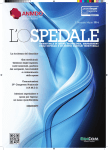
Agilent 1200 Series
Thermostatted Column
Compartment
G1316A/G1316B/G1316C
User Manual
1200 Series TCC User Manual
Agilent Technologies
Notices
© Agilent Technologies, Inc. 1995,
1996-2008
No part of this manual may be reproduced
in any form or by any means (including electronic storage and retrieval or translation
into a foreign language) without prior agreement and written consent from Agilent
Technologies, Inc. as governed by United
States and international copyright laws.
Manual Part Number
G1316-90011
Edition
09/2008
Printed in Germany
Agilent Technologies
Hewlett-Packard-Strasse 8
76337 Waldbronn
Research Use Only
Not for use in Diagnostic Procedures.
Manual Structure
The User Manual G1316-90011 (English)
and its localized versions contain a subset
of the Service Manual and is shipped with
the Thermostatted Column Compartment in
printed matter.
Latest versions of the manuals can be
obtained from the Agilent web.
Warranty
The material contained in this document is provided “as is,” and is subject to being changed, without notice,
in future editions. Further, to the maximum extent permitted by applicable
law, Agilent disclaims all warranties,
either express or implied, with regard
to this manual and any information
contained herein, including but not
limited to the implied warranties of
merchantability and fitness for a particular purpose. Agilent shall not be
liable for errors or for incidental or
consequential damages in connection
with the furnishing, use, or performance of this document or of any
information contained herein. Should
Agilent and the user have a separate
written agreement with warranty
terms covering the material in this
document that conflict with these
terms, the warranty terms in the separate agreement shall control.
receive no greater than Restricted Rights as
defined in FAR 52.227-19(c)(1-2) (June
1987). U.S. Government users will receive
no greater than Limited Rights as defined in
FAR 52.227-14 (June 1987) or DFAR
252.227-7015 (b)(2) (November 1995), as
applicable in any technical data.
Safety Notices
CAUTION
A CAUTION notice denotes a
hazard. It calls attention to an
operating procedure, practice, or
the like that, if not correctly performed or adhered to, could
result in damage to the product
or loss of important data. Do not
proceed beyond a CAUTION
notice until the indicated conditions are fully understood and
met.
Technology Licenses
The hardware and/or software described in
this document are furnished under a license
and may be used or copied only in accordance with the terms of such license.
Restricted Rights Legend
If software is for use in the performance of a
U.S. Government prime contract or subcontract, Software is delivered and licensed as
“Commercial computer software” as
defined in DFAR 252.227-7014 (June 1995),
or as a “commercial item” as defined in FAR
2.101(a) or as “Restricted computer software” as defined in FAR 52.227-19 (June
1987) or any equivalent agency regulation
or contract clause. Use, duplication or disclosure of Software is subject to Agilent
Technologies’ standard commercial license
terms, and non-DOD Departments and
Agencies of the U.S. Government will
WA R N I N G
A WARNING notice denotes a
hazard. It calls attention to an
operating procedure, practice,
or the like that, if not correctly
performed or adhered to, could
result in personal injury or
death. Do not proceed beyond a
WARNING notice until the indicated conditions are fully understood and met.
1200 Series TCC User Manual
In This Guide…
In This Guide…
This manual covers the Agilent 1200 Series Thermostatted Column
Compartments (TCC)
• G1316A Agilent 1200 Series TCC
• G1316B Agilent 1200 Series TCC SL
• G1316C Agilent 1200 Series TCC SL Plus
1 Introduction to the Column Compartment
This chapter gives an introduction to the TCC, instrument overview and
internal connectors.
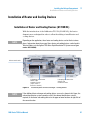
3 Installing the Column Compartment
This chapter describes the installation of the Thermostatted Column
Compartment.
4 How to optimize the Column Compartment
This chapter provides information on how to optimize the Thermostatted
Column Compartement.
5 Troubleshooting and Diagnostics
Overview about the troubleshooting and diagnostic features.
6 Test Functions
This chapter describes the TCC’s built in test functions.
1200 Series TCC User Manual
3
In This Guide…
7 Maintenance
This chapter describes the maintenance of the TCC.
8 Parts and Materials for Maintenance
This chapter provides information on parts for maintenance.
9 Appendix
This chapter provides addition information on safety, legal and web.
4
1200 Series TCC User Manual
Contents
Contents
1 Introduction to the Column Compartment
9
Main Features 10
System Overview 11
Column-Identification System 13
Column Switching Valve (Optional for G1316A/G1316B SL)
Electrical Connections 18
Instrument Layout 21
Agilent Diagnostic Software 22
2 Site Requirements and Specifications
23
Site Requirements and Specifications 24
Physical Specifications 27
Performance Specifications 28
Extended Specifications on G1316B SL/G1316C SL Plus
3 Installing the Column Compartment
15
30
33
Unpacking the Column Compartment 34
Optimizing the Stack Configuration 35
Installing the Column Compartment 38
Installing Valve Heads (G1316C SL Plus) 42
Flow Connections of the Column Compartment 44
Installation of Heater and Cooling Devices 47
Placing Columns 49
4 How to optimize the Column Compartment
51
Optimizing the Performance of your Column Compartment
Using Additional Heater and Cooling Devices 53
1200 Series TCC User Manual
52
5
Contents
5 Troubleshooting and Diagnostics
55
Overview of the Column Department’s Indicators and Test Functions
Status Indicators 57
Available Tests depending on User Interfaces 59
Agilent Diagnostic Software 60
6 Test Functions
61
Thermostat Function Test 62
Pressure Test 65
Column Thermostat Temperature Calibration
7 Maintenance
56
66
71
Introduction to Maintenance and Repair 72
Warnings and Cautions 73
Overview of Maintenance 75
Cleaning the Column Compartment 76
Changing Column Identification Tags 77
Replacing Head Parts of Column Switching Valve (G1316A/G1316B SL)
Adding Heater and Cooling Devices (G1316B SL/G1316C SL Plus) 82
Correcting Leaks 84
Replacing the Column Compartment’s Firmware 85
Replacing Valve Heads (G1316C SL Plus) 86
Preparing the G1316C SL Plus for Transportation 89
8 Parts and Materials for Maintenance
79
91
Valve Options Overview 92
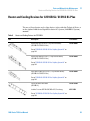
Heater and Cooling Devices for G1316B SL/G1316C SL Plus 93
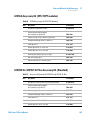
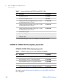
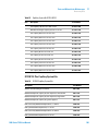
Column Switching Valve 2 Position/6 Port (G1316A/G1316B SL) 95
Column Switching Valve 8 Position-9 Port (G1316C SL Plus) 97
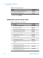
Micro Column Switching Valve 2 Postion/6 Port (G1316A/G1316B SL) 99
Micro Column Switching Valve 2 Position/10 Port (G1316A/G1316B SL) 100
Accessory Kits 102
Plastic Parts 109
Leak Parts 110
6
1200 Series TCC User Manual
Contents
9 Appendix
113
Safety Symbols 114
The Waste Electrical and Electronic Equipment Directive
Lithium Batteries Information 118
Radio Interference 119
Sound Emission 120
Solvent Information 121
Agilent Technologies on Internet 123
1200 Series TCC User Manual
117
7
Contents
8
1200 Series TCC User Manual
1200 Series TCC User Manual
1
Introduction to the Column
Compartment
Main Features
10
System Overview
11
Column-Identification System
13
Column Switching Valve (Optional for G1316A/G1316B SL)
Electrical Connections 18
Serial Number Information
Instrument Layout
15
20
21
Agilent Diagnostic Software
22
This chapter gives an introduction to the TCC, instrument overview and
internal connectors.
Agilent Technologies
9
1
Introduction to the Column Compartment
Main Features
Main Features
The Agilent 1200 Series thermostatted column compartments are stackable
temperature-controlled column compartments for LC. They are available as
standalone modules or as a component of a Agilent 1200 Series system. They
are used for heating and cooling to meet extreme requirements of retention
time reproducibility.
The main features are:
• Peltier heating and cooling from 10 degrees below ambient up to
80 °C(G1316A) or 100 °C (G1316B SL/G1316C SL Plus) with high heating
and cooling speeds for maximum application flexibility and stability,
• holds up to three 30-cm columns and optimized design gives minimum dead
volumes and maximum efficiency,
• two independently programmable heat exchangers contribute volumes of
only 3 and 6 µl,
• G1316B SL features additional heating and cooling devices for low flow
rates, which reduce the risk of additional dispersion,
• G1316B SL and G1316C SL Plus can be supplemented by a kit to install a
small heat-exchanger with 1.6 µl delay volume to reduce the delay volume.
In additon a cooling device with 1.5 µl is available,
• electronic column-identification module as standard for GLP
documentation of column type, and major column parameters,
• optional high-quality Rheodyne® column switching valves with ceramic
stator-face assemblies for prolonged lifetime.
For specifications, see “Performance Specifications” on page 28.
10
1200 Series TCC User Manual
1
Introduction to the Column Compartment
System Overview
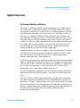
System Overview
The Concept of Heating and Cooling
The design of this thermostatted column compartment uses column heating
and cooling devices with Peltier elements. The solvent entering the column
compartment is heated up or cooled down to a settable temperature with two
low-volume heat exchangers (3 µl on left side, 6 µl on right side), made of a
short piece of capillary 0.17 mm i.d. leading through a heat exchanger. The
heat exchanger is designed such that it can function simultaneously as an air
heater. The shape of the heat exchanger surface allows the area around the
column to be kept at a similar temperature level as the liquid running through
the column. This is done by thermal convection and radiation between the
heat exchanger fins. This design ensures that the column and the solvent
flowing through it are almost at the same temperature.
Actual temperature control is accomplished at the heat exchanger. The solvent
cools down or heats up on its transfer from the heating block to the column
inlet. This depends on several factors: flow rate, setpoint temperature,
ambient temperature and column dimensions.
In a flow-through temperature regulation system, there are necessarily slightly
different temperatures at different positions. If, for example, the temperature
set by the user is 40 °C, then the heat exchanger is regulated to a temperature
40.8 °C which is different by a certain offset (here. 0.8 °C). The solvent
temperature at the column entry would be about 39 °C.
The actual temperature displayed on the user interface is always the derived
temperature taken at the heat exchanger, corrected by the offset explained
above.
Any type of heated column compartment brings one important consequence
for column temperature equilibration. Before an equilibrium is reached, the
whole mass of column, column packing, and solvent volume inside the column
has to be brought to the selected temperature. This depends on several factors:
flow rate, setpoint temperature, ambient temperature and column dimensions.
The higher the flow rate, the faster the column equilibrates (due to
thermostatted mobile phase).
1200 Series TCC User Manual
11
1
Introduction to the Column Compartment
System Overview
“Column Thermostat Temperature Calibration” on page 66 shows a setpoint
temperature of 40 °C. Some time after entering the setpoint the heat
exchanger has reached its temperature and the control activity starts. The
TEMPERATURE NOT READY signal will be cancelled 20 seconds after the sensed
temperature was within a range of ± 0.5 °C of the setpoint (other values can be
set via the user interface). However this does not necessarily mean that the
column has already reached the correct temperature. The equilibration of the
column may take longer. Stability of the pressure signal is a good indication
for equilibrium.
IZbeZgVijg8
=ZViZmX]Vc\ZgiZbeZgVijgZ
8dajbciZbeZgVijgZ
:mVbeaZ[dgV[adlgViZd[*ba$b^cd[lViZg
I^bZb^c
Figure 1
Equilibration of Heat Exchanger and Column Temperature
The temperature calibration and verification is described in the Service
Manual.
12
1200 Series TCC User Manual
Introduction to the Column Compartment
Column-Identification System
1
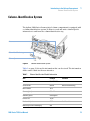
Column-Identification System
The Agilent 1200 Series thermostatted column compartment is equipped with
a column-identification system. It allows to read and write column-specific
information to and from the column-identification tag.
6ciZccVh
8dajbc"^YZci^[^XVi^dciV\
8dajbcXa^e
Figure 2
Column-Identification System
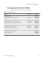
Table 1 on page 13 shows the information that can be stored. The information
fields can be edited via the user interface.
Table 1
Column-Identification Module Information
Item
Example
Product number
79916OD-552
Serial number
950522
Batch number
1675
Geometry [mm]
100 × 2.1
Stationary phase
ODS Hypersil
Particle size
10 µm
Number of injections
1267
Maximum pressure allowed [bar]
400
1200 Series TCC User Manual
Comment
Date of manufacturing
See Note below.
13
1
Introduction to the Column Compartment
Column-Identification System
Table 1
Column-Identification Module Information
Item
Example
Maximum temperature recommended [°C]
70
Maximum pH recommended
12
Comment
Column void volume [ml]
The number of injections will be updated each run to create a column lifecycle
(history). The user interface allows to edit all information.
NOTE
14
If a column switching valve (see “Column Switching Valve (Optional for G1316A/G1316B
SL)” on page 15) is installed in the module, the update of the number of injections depends
on the position of the column switching valve. For example, if the left column is selected,
the right column is not updated, and vice versa. If no column switching valve is installed
both sides are updated at the same time.
1200 Series TCC User Manual
Introduction to the Column Compartment
Column Switching Valve (Optional for G1316A/G1316B SL)
1
Column Switching Valve (Optional for G1316A/G1316B SL)
Figure 3
1200 Series TCC User Manual
Location of Column Switching Valve
15
1
Introduction to the Column Compartment
Column Switching Valve (Optional for G1316A/G1316B SL)
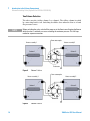
Two Column Selection
The valve can select either column 1 or column 2. The offline column is sealed
by connecting head to tail. Switching should be done when the flow is off and
the pressure is zero.
NOTE
Before switching the valve, switch off the pump or set the flow to zero. Keeping the flow on
while the valve is switched can cause exceeding the maximum pressure. This will stop
method or sequence execution.
;gdbVjidhVbeaZg
=ZViZgVhhZbWan&
=ZViZgVhhZbWan'
8dajbc&
8dajbc'
IdYZiZXidg
Figure 4
Column 1 Active
;gdbVjidhVbeaZg
=ZViZgVhhZbWan'
=ZViZgVhhZbWan&
8dajbc'
8dajbc&
IdYZiZXidg
Figure 5
16
Column 2 Active
1200 Series TCC User Manual
Introduction to the Column Compartment
Column Switching Valve (Optional for G1316A/G1316B SL)
1
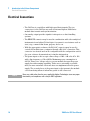
Precolumn Back-flushing
The sample is injected into series-connected precolumn and analytical
column. After the valve has switched, the analytical column flow continues in
normal direction. Only the precolumn is back-flushed, eluting highly retained
peaks directly to the detector.
;gdbVjidhVbeaZg
=ZViZgVhhZbWan'
=ZViZgVhhZbWan&
EgZXdajbc
6cVani^XVa
8dajbc
IdYZiZXidg
Figure 6
1200 Series TCC User Manual
Precolumn Back-flushing
17
1
Introduction to the Column Compartment
Electrical Connections
Electrical Connections
• The CAN bus is a serial bus with high speed data transfer. The two
connectors for the CAN bus are used for internal Agilent 1200 Series
module data transfer and synchronization.
• One analog output provides signals for integrators or data handling
systems.
• The REMOTE connector may be used in combination with other analytical
instruments from Agilent Technologies if you want to use features such as
start, stop, common shut down, prepare, and so on.
• With the appropriate software, the RS-232C connector may be used to
control the module from a computer through a RS-232C connection. This
connector is activated and can be configured with the configuration switch.
See your software documentation for further information.
• The power input socket accepts a line voltage of 100 – 240 volts AC ± 10%
with a line frequency of 50 or 60 Hz. Maximum power consumption is
220 VA. There is no voltage selector on your module because the power
supply has wide-ranging capability. There are no externally accessible
fuses, because automatic electronic fuses are implemented in the power
supply. The security lever at the power input socket prevents the module
cover from being taken off when line power is still connected.
NOTE
18
Never use cables other than the ones supplied by Agilent Technologies to ensure proper
functionality and compliance with safety or EMC regulations.
1200 Series TCC User Manual
Introduction to the Column Compartment
Electrical Connections
1
HZXjg^inaZkZg
6E<GZbdiZ
GH"'('8
86C
8dc[^\jgVi^dchl^iX]
EdlZg
hV[ZinhiVcYVgYh
Xdc[^\jgVi^dchl^iX]
hZii^c\h
kdaiV\ZgVc\Z
edlZgXdchjbei^dc$
[gZfjZcXn
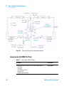
Figure 7
1200 Series TCC User Manual
Rear View of Oven - Electrical Connections and Label
19
1
Introduction to the Column Compartment
Electrical Connections
Serial Number Information
The serial number information on the instrument labels provide the following
information:
20
CCYWWSSSSS
Format
CC
country of manufacturing
• DE = Germany
• JP = Japan
• CN = China
YWW
year and week of last major manufacturing change, e.g. 820
could be week 20 of 1998 or 2008
SSSSS
real serial number
1200 Series TCC User Manual
Introduction to the Column Compartment
Instrument Layout
1
Instrument Layout
The industrial design of the module incorporates several innovative features.
It uses Agilent’s E-PAC concept for the packaging of electronics and
mechanical assemblies. This concept is based upon the use of expanded
polypropylene (EPP) layers foam plastic spacers in which the mechanical and
electronic boards components of the module are placed. This pack is then
housed in a metal inner cabinet which is enclosed by a plastic external
cabinet. The advantages of this packaging technology are:
• virtual elimination of fixing screws, bolts or ties, reducing the number of
components and increasing the speed of assembly/disassembly,
• the plastic layers have air channels molded into them so that cooling air can
be guided exactly to the required locations,
• the plastic layers help cushion the electronic and mechanical parts from
physical shock, and
• the metal inner cabinet shields the internal electronics from
electromagnetic interference and also helps to reduce or eliminate radio
frequency emissions from the instrument itself.
1200 Series TCC User Manual
21
1
Introduction to the Column Compartment
Agilent Diagnostic Software
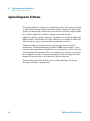
Agilent Diagnostic Software
The Agilent Diagnostic Software is a standalone product that can be used with
or without data system. Agilent Lab Advisor helps to manage the lab for high
quality chromatographic results and can monitor in real time a single Agilent
LC or all the Agilent GCs and LCs configured on the lab intranet.
Agilent Lab Advisor provides diagnostic capabilities for all Agilent 1200 Series
HPLC modules. This includes tests and calibrations procedures as well as the
different injector steps to perform all the maintenance routines.
Agilent Lab Advisor also allows users to monitor the status of their LC
instruments. The Early Maintenance Feedback (EMF) feature helps to carry
out preventive maintenance. In addition, users can generate a status report for
each individual LC instrument. The tests and diagnostic features as provided
by the Agilent Lab Advisor Software may differ from the descriptions in this
manual. For details refer to the Agilent Lab Advisor help files.
This manual provides lists with the names of Error Messages, Not Ready
messages, and other common issues.
22
1200 Series TCC User Manual
1200 Series TCC User Manual
2
Site Requirements and Specifications
Site Requirements and Specifications
Power Consideration 24
Power Cords 25
Bench Space 26
Environment 26
Physical Specifications
24
27
Performance Specifications
28
Extended Specifications on G1316B SL/G1316C SL Plus
Agilent Technologies
30
23
2
Site Requirements and Specifications
Site Requirements and Specifications
Site Requirements and Specifications
A suitable environment is important to ensure optimal performance of the
instrument.
Power Consideration
The module power supply has wideranging capability (see Table 2 on page 27).
It accepts any line voltage in the range described in the above mentioned table.
Consequently there is no voltage selector in the rear of the module. There are
also no externally accessible fuses, because automatic electronic fuses are
implemented in the power supply.
WA R N I N G
Incorrect line voltage at the instrument
Shock hazard or damage of your instrumentation can result, if the devices are
connected to a line voltage higher than specified.
➔ Connect your instrument to the specified line voltage.
WA R N I N G
Module is partially energized when switched off, as long as the power cord is
plugged in.
Repair work at the module can lead to personal injuries, e.g. shock hazard, when the
cover is opened and the module is connected to power.
➔ Remove the power cable from the instrument before opening the cover.
➔ Do not connect the power cable to the Instrument while the covers are removed.
24
1200 Series TCC User Manual
2
Site Requirements and Specifications
Site Requirements and Specifications
CAUTION
Unaccessable power plug.
In case of emergency it must be possible to disconnect the instrument from the power
line at any time.
➔ Make sure the power connector of the instrument can be easily reached and
unplugged.
➔ Provide sufficient space behind the power socket of the instrument to unplug the
cable.
Power Cords
Different power cords are offered as options with the module. The female end
of all power cords is identical. It plugs into the power-input socket at the rear
of the module. The male end of each power cord is different and designed to
match the wall socket of a particular country or region.
WA R N I N G
The absence of ground connection and the use of an unspecified power cord can
lead to electric shock or short circuit.
Electric Shock
➔ Never operate your instrumentation from a power outlet that has no ground
connection.
➔ Never use a power cord other than the Agilent Technologies power cord designed
for your region.
WA R N I N G
Use of unsupplied cables
Using cables not supplied by Agilent Technologies can lead to damage of the
electronic components or personal injury.
➔ Never use cables other than the ones supplied by Agilent Technologies to ensure
proper functionality and compliance with safety or EMC regulations.
1200 Series TCC User Manual
25
2
Site Requirements and Specifications
Site Requirements and Specifications
Bench Space
The column compartment dimensions and weight (see “Physical
Specifications” on page 27 ) allow to place this module on almost any desk or
laboratory bench. It needs an additional 2.5 cm (1.0 inches) of space on either
side and approximately 8 cm (3.1 inches) in the rear for the circulation of air
and electric connections.
If the bench should carry a complete Agilent Series system, make sure that
the bench is designed to carry the weight of all the modules.
The module should be operated in a horizontal position.
Environment
Your column compartment will work within specifications at ambient
temperatures and relative humidity as described in “Physical
Specifications” on page 27.
26
1200 Series TCC User Manual
2
Site Requirements and Specifications
Physical Specifications
Physical Specifications
Table 2
Physical Specifications
Type
Specification
Weight
10.2 kg (22.5 lbs)
Dimensions
(width × depth × height)
410 × 435 × 140 mm (16.1 × 17 × 5.5
inches)
Line voltage
100 – 240 VAC, ± 10%
Line frequency
50 or 60 Hz, ± 5%
Power consumption
320 VA / 150 W / 512 BTU
Ambient operating
temperature
0 – 55 °C (32 – 131 °F)
Ambient non-operating
temperature
-40–70 °C (-4–158 °F)
Humidity
< 95%, at 25–40 °C (77–104 °F)
Operating Altitude
Up to 2000 m (6500 ft)
Non-operating altitude
Up to 4600 m (14950 ft)
For storing the module
Safety standards: IEC, CSA,
UL
Installation Category II, Pollution
Degree 2
For indoor use only. Research
Use Only. Not for use in
Diagnostic Procedures.
1200 Series TCC User Manual
Comments
Wide-ranging capability
Maximum
Non-condensing
27
2
Site Requirements and Specifications
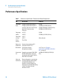
Performance Specifications
Performance Specifications
Table 3
28
Performance Specifications Thermostatted Column Compartment
Type
Specification
Comments
Temperature
range
10 degrees below ambient to 80 °C
10 degrees below ambient to 100 °C
G1316A
G1316B (SL)/G1316C (SL Plus)
up to 80 °C: flow rates up to 5 ml/min
up to 100 °C: flow rates up to
2.5 ml/min
G1316A/G1316B (SL)/G1316C (SL Plus)
G1316B (SL)/G1316C (SL Plus)
Temperature
stability
± 0.15 °C
± 0.05 °C
G1316A
G1316B (SL)/G1316C (SL Plus)
Temperature
accuracy
± 0.8 °C
± 0.5 °C
With calibration
Column
capacity
Three 30 cm
Warm-up/co
ol-down time
5 minutes from ambient to 40 °C
10 minutes from 40 – 20 °C
Dead volume
3 µl left heat exchanger
6 µl right heat exchanger
i.d. 0.17 mm, see “Extended
Specifications on G1316B SL/G1316C SL
Plus” on page 30
Communicati
ons
Controller-area network (CAN), GPIB,
RS-232C, APG Remote: ready, start,
stop and shut-down signals, LAN via
other 1200 series module
no GPIB on G1316B (SL)/G1316C (SL
Plus)
Safety and
maintenance
Extensive diagnostics, error detection
and display (through control module
and Agilent ChemStation), leak
detection, safe leak handling, leak
output signal for shutdown of pumping
system. Low voltages in major
maintenance areas.
1200 Series TCC User Manual
Site Requirements and Specifications
Performance Specifications
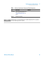
Table 3
NOTE
2
Performance Specifications Thermostatted Column Compartment
Type
Specification
GLP features
Column-identification module for GLP
documentation of column type, see
“Column-Identification System” on
page 13
Housing
All materials recyclable.
Comments
All specifications are valid for distilled water at ambient temperature (25 °C), set point at
40 °C and a flow range from 0.2–5 ml/min.
1200 Series TCC User Manual
29
2
Site Requirements and Specifications
Extended Specifications on G1316B SL/G1316C SL Plus
Extended Specifications on G1316B SL/G1316C SL Plus
The 1200 series G1316B SL/G1316C SL Plus thermostatted column
compartment is usable from 10 °C below ambient up to 80 °C for flow ranges
up to 5 ml/min and up to 100 °C for flow ranges up to 2.5 ml/min. Additional
heating and cooling devices are available for the G1316B SL/G1316C SL Plus
to reduce the risk of additional dispersion at low flow rates see Figure 8 on
page 30. These devices can be installed in any position in the column
compartment, see “Installation of Heater and Cooling Devices (G1316B
SL)” on page 47.
A"h]VeZYegZ"Xdajbc
]ZViZg=ZViZg
adc\"je
A"h]VeZYegZ"Xdajbc
]ZViZg=ZViZg
adc\"Ydlc
A"h]VeZYegZ"Xdajbc]ZViZg
KdajbZ/&#+¥a
bdjciZYdcXVgg^Zg
ide[dgXdajbc&!
Wdiidb[dgXdajbc'
Figure 8
J"h]VeZYedhi"XdajbcXddaZg
KdajbZ/&#*¥a
bdjciZYdcXVgg^Zg
New additional heater and cooling devices
The standard column compartment is equipped with a 3 µl and 6 µl heater or
cooler. Both can be set at the same or different temperature. To reduce the
delay volume, a kit (“G1316B SL/G1316C SL Plus Capillary System Kit” on
page 104) has been set up for installing a small heaters with 1.6 µl internal
delay volume and also a new cooling device with 1.5 µl internal volume is
available.
30
1200 Series TCC User Manual
2
Site Requirements and Specifications
Extended Specifications on G1316B SL/G1316C SL Plus
NOTE
If the additional heater and cooling devices are used as shown in Figure 8 on page 30, the
column identification system cannot be used. If the column identification system is
required, fix the heater and cooling devices in the upper or lower locations or fix them
right/left of the current location.
1200 Series TCC User Manual
31
2
32
Site Requirements and Specifications
Extended Specifications on G1316B SL/G1316C SL Plus
1200 Series TCC User Manual
1200 Series TCC User Manual
3
Installing the Column Compartment
Unpacking the Column Compartment
Delivery Checklist 34
Optimizing the Stack Configuration
Installing the Column Compartment
34
35
38
Installing Valve Heads (G1316C SL Plus)
42
Flow Connections of the Column Compartment
Installation of Heater and Cooling Devices
Placing Columns 49
Column-Identification Tag
Column Clip 50
44
47
49
This chapter describes the installation of the Thermostatted Column
Compartment.
Agilent Technologies
33
3
Installing the Column Compartment
Unpacking the Column Compartment
Unpacking the Column Compartment
If the delivery packaging shows signs of external damage, please call your
Agilent Technologies sales and service office immediately. Inform your service
representative that the module may have been damaged during shipment.
CAUTION
"Defective on arrival" problems
If there are signs of damage, please do not attempt to install the module. Inspection by
Agilent is required to evaluate if the instrument is in good condition or damaged.
➔ Notify your Agilent sales and service office about the damage.
➔ An Agilent service representative will inspect the instrument at your site and
initiate appropriate actions.
Delivery Checklist
Ensure all parts and materials have been delivered with the module. The
delivery checklist is shown below. Please report missing or damaged parts to
your local Agilent Technologies sales and service office.
Table 4
34
Column Compartment Delivery Checklist
Description
Quantity
Thermostatted column compartment
1
Power cable
1
CAN cable
1
Column switching valve
optional
User Manual
1
Accessory kit (see “Accessory Kits” on
page 102)
1
1200 Series TCC User Manual
3
Installing the Column Compartment
Optimizing the Stack Configuration
Optimizing the Stack Configuration
If your column compartment is part of a Agilent 1200 Series system, you can
ensure optimum performance by installing the following configuration. This
configuration optimizes the system flow path and ensures minimum delay
volume.
For installations of the G1316C SL Plus as part of the Method Development
Solution, please refer to the Method Development Solution User and
Installation Guide part number: G4230-90000.
1200 Series TCC User Manual
35
3
Installing the Column Compartment
Optimizing the Stack Configuration
HdakZciXVW^cZi
KVXjjbYZ\VhhZg
Ejbe
AdXVa
JhZg>ciZg[VXZ
6jidhVbeaZg
8dajbcXdbeVgibZci
9ZiZXidg
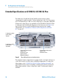
Figure 9
36
Recommended Stack Configuration (Front View)
1200 Series TCC User Manual
Installing the Column Compartment
Optimizing the Stack Configuration
3
68edlZg
GZbdiZXVWaZ
86C7jhXVWaZid
adXVajhZg^ciZg[VXZ
86C7jhXVWaZ
A6CidA8
8]ZbHiVi^dcadXVi^dc
YZeZcYhdcYZiZXidg
6cVad\YZiZXidg
h^\cVa
&dg'djiejiheZg
YZiZXidg
Figure 10
1200 Series TCC User Manual
Recommended Stack Configuration (Rear View)
37
3
Installing the Column Compartment
Installing the Column Compartment
Installing the Column Compartment
Parts required
#
Description
1
Column compartment
1
Power cord
For other cables see text below
Preparations
Locate bench space.
Provide power connections.
Unpack the Column compartment.
WA R N I N G
Module is partially energized when switched off, as long as the power cord is
plugged in.
Risk of stroke and other personal injury. Repair work at the module can lead to
personal injuries, e. g. shock hazard, when the module cover is opened and the
instrument is connected to power.
➔ Never perform any adjustment, maintenance or repair of the module with the top
cover removed and with the power cord plugged in.
➔ The security lever at the power input socket prevents that the module cover is taken
off when line power is still connected. Never plug the power line back in when cover
is removed.
CAUTION
Valve properties are read from the valve head RFID tag during initialization of the
module. Valve properties will not be updated, if the valve head is replaced while the
module is on.
Selection of valve port positions can fail, if the instrument does not know the
properties of the installed valve.
➔ Always switch off the instrument when replacing the valve head.
38
1200 Series TCC User Manual
3
Installing the Column Compartment
Installing the Column Compartment
CAUTION
The valve actuator contains sensitive optical parts, which need to be protected from
dust and other pollutions. Pollution of these parts can impair the accurate selection of
valve ports and therefore bias measurement results.
➔ Always install a valve head for operation and storage. For protecting the actuator, a
dummy valve head (part of transportation lock kit part number: G1316-67001) can be
used instead of a functional valve. Do not touch parts inside the actuator.
If the Thermostatted Column Compartment SL Plus (G1316C SL Plus only)
includes the valve drive option, it is shipped with a transportation lock, which
needs to be removed during installation.
1 Remove the 5 screws, which hold the lock in position (G1316C SL Plus
only).
2 Remove the dummy valve head by unscrewing the cap nut and removing it
from the valve drive (G1316C SL Plus only).
1200 Series TCC User Manual
39
3
Installing the Column Compartment
Installing the Column Compartment
3 Place the column compartment in the stack or on the bench in a horizontal
position.
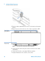
4 Ensure the power switch at the front of the column compartment is OFF.
HiVijh^cY^XVidg
\gZZc$nZaadl$gZY
A^cZedlZghl^iX]
l^i]\gZZca^\]i
Figure 11
Front View of the Thermostatted Column Compartment
5 Connect the power cable to the power connector at the rear of the column
compartment.
6 Connect the CAN cable to other Agilent 1200 Series modules.
7 If Agilent ChemStation is the controller, connect either
40
1200 Series TCC User Manual
Installing the Column Compartment
Installing the Column Compartment
3
• the LAN connection to the LAN interface board in the module or
• the GPIB cable to the module.
NOTE
If a Agilent DAD/MWD/FLD is in the system, the LAN/GPIB should be connected to the
DAD/MWD/FLD (due to higher data load).
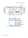
8 Connect the APG Remote cable (optional) for non-Agilent 1200 Series
instruments.
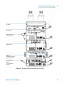
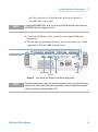
9 Turn ON power by pushing the button at the lower left side of the column
compartment. The status LED should be green.
HZXjg^inaZkZg
8dc[^\jgVi^dchl^iX]
86C
6E<GZbdiZ
GH"'('8
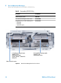
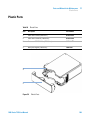
Figure 12
NOTE
EdlZg
Rear View of the Thermostatted Column Compartment
The column compartment is turned on when the line power switch is pressed and the green
indicator lamp is illuminated. The column compartment is turned off when the line power
switch is protruding and the green light is OFF.
1200 Series TCC User Manual
41
3
Installing the Column Compartment
Installing Valve Heads (G1316C SL Plus)
Installing Valve Heads (G1316C SL Plus)
Several optional valve heads are available for the G1316C SL Plus, which can
be installed and exchanged easily.
Parts required
CAUTION
#
Part number
Description
1
5067-4107
8pos/9prt valve head high pressure and/or
1
5067-4108
8pos/9prt valve head low pressure
Valve Damage
Using a low pressure valve on the high pressure side can damage the valve.
➔ When using multiple column compartments as part of a method development
solution, make sure that the high pressure valve head is connected to the
autosampler and the low pressure valve head is connected to the detector.
➔ For details, please refer to the Method Development Solution User and Installation
Guide (part number: G4230-90000).
CAUTION
Column Damage or Bias Measurement Results
Switching the valve to a wrong position can damage the column or bias measurement
results.
➔ Fitting the lobe to the groove is essential for making sure the valve is switched to
the correct position.
42
1200 Series TCC User Manual
3
Installing the Column Compartment
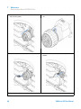
Installing Valve Heads (G1316C SL Plus)
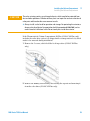
1 Put the valve head onto the valve drive such that the lobe 2 Screw the valve head onto the valve drive using the union
fits to the groove.
nut.
3 Install all required capillary connections to the valve head. 4 Push the valve head until it snaps in and stays in the rear
position.
1200 Series TCC User Manual
43
3
Installing the Column Compartment
Flow Connections of the Column Compartment
Flow Connections of the Column Compartment
Parts required
Description
Other modules
Parts from accessory kit, see “Accessory Kits” on page 102
Two wrenches 1/4 – 5/16 inch for capillary connections
Preparations
WA R N I N G
Install the column compartment
Toxic and hazardous solvents
The handling of solvents and reagents can hold health risks.
➔ When working with solvents observe appropriate safety procedures (for example,
goggles, safety gloves and protective clothing) as described in the material handling
and safety data sheet supplied by the solvent vendor, especially when toxic or
hazardous solvents are used.
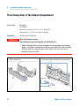
1 Press release buttons and remove front cover to gain
access to heater area.
2 The column compartment is equipped with an
column-identification system that can read column tags.
6ciZccVh
8dajbciV\
8dajbcXa^e
44
1200 Series TCC User Manual
Installing the Column Compartment
Flow Connections of the Column Compartment
NOTE
3
NOTE
For more information on column identification, see
“Column-Identification System” on page 13 .
The internal volumes of the heat exchanger assemblies
comprise a volume of 3 µl (left) and 6 µl (right). The internal
capillary diameter is 0.17 mm.
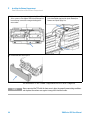
3 Place the column on the left heat exchanger assembly
4 Or place the column on the right heat exchanger
and connect the capillaries to the column.
;gdbVjidhVbeaZg
assembly and connect the capillaries to the column.
8a^e
IdYZiZXidg
NOTE
5 Fix the column with the column clip from the accessory
kit.
See “Column Switching Valve (Optional for G1316A/G1316B
SL)” on page 15.
on how to connect the column selection valve.
1200 Series TCC User Manual
45
3
Installing the Column Compartment
Flow Connections of the Column Compartment
6 If the column compartment is not part of a Agilent 1200
Series system, or if an Agilent 1200 Series Autosampler is
located on top, connect the corrugated tubing to the
waste outlet.
7 Route tubings from modules above through the openings
in the funnel holder (top) and the plastic bottom part.
Remove small plastic plugs first.
8 Put the front cover back in place.
The installation of the column compartment has now been completed.
NOTE
46
Always operated the TCC with the front cover in place for proper thermostatting conditions
and to protect the column area against strong drafts from the ouside.
1200 Series TCC User Manual
3
Installing the Column Compartment
Installation of Heater and Cooling Devices
Installation of Heater and Cooling Devices
Installation of Heater and Cooling Devices (G1316B SL)
With the introduction of the 1200 series TCC SL (G1316B SL), the heater
elements were redesigned in order to allow the adding of small heater and
cooling devices.
NOTE
Depending on the application, these heater and cooling devices can be fixed at various
places. Information about the usage of these heater and cooling devices can be found in
Technical Notes or in the Agilent 1200 Series Rapid Resolution LC System manual (part
number: G1312-90300).
]daZhidViiVX]XVgg^Zg
A"h]VeZYegZ"Xdajbc]ZViZg
KdajbZ/&#+¥a
bdjciZYdcXVgg^Zg
ide[dgXdajbc&!
Wdiidb[dgXdajbc'
Figure 13
NOTE
J"h]VeZYedhi"XdajbcXddaZg
KdajbZ/&#*¥a
bdjciZYdcXVgg^Zg
Installation points for heat exchanger / cooling devices
If the additional heat exchanger and cooling devices are used as shown in this figure, the
column identification system cannot be used. If the column identification system is
required, fix the heater and cooling devices in the upper or lower locations or right/left of
the current location.
1200 Series TCC User Manual
47
3
Installing the Column Compartment
Installation of Heater and Cooling Devices
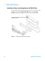
Installation of Heater and Cooling Devices (G1316C SL Plus)
For the G1316C SL Plus, additional heat exchanger and cooling devices can be
installed on the carrier part number: G1316-89200 using 3 screws (part number:
0515-1052), included to part number for carrier) as shown in figure below.
7j^aY"^c]ZViZmX]Vc\Zg
Figure 14
48
Installing the low dispersion heat exchangers
1200 Series TCC User Manual
Installing the Column Compartment
Placing Columns
3
Placing Columns
Column-Identification Tag
When correctly placed on the heat exchanger, the distance between the
column-identification tag and antenna is 1–2 mm. This is the optimum
distance for proper function. The identification tag can be easily removed from
the column.
NOTE
For columns with small diameter, a cable tie wrap should be used to fix the column
identification tag to the column. Assure that the tie wrap does not block the front cover.
NOTE
The tag needs to be placed differently, depending on whether the column is installed at the
left or right heat exchanger, see Figure 15 on page 49 and Figure 16 on page 50. The Agilent
logo should always be at front.
8dajbc"^YZci^[^XVi^dciV\
Figure 15
1200 Series TCC User Manual
Column-Identification Tag for Left Heat Exchanger
49
3
Installing the Column Compartment
Placing Columns
8dajbc"^YZci^[^XVi^dciV\
Figure 16
Column-Identification Tag for Right Heat Exchanger
Column Clip
For better positioning of the column on the heat exchanger a column clip is
available (see “Accessory Kits” on page 102).
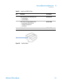
Figure 17
50
Column Clip (part number 5063-6526, pack of 6)
1200 Series TCC User Manual
1200 Series TCC User Manual
4
How to optimize the Column
Compartment
Optimizing the Performance of your Column Compartment
Using Additional Heater and Cooling Devices
52
53
This chapter provides information on how to optimize the Thermostatted
Column Compartement.
Agilent Technologies
51
4
How to optimize the Column Compartment
Optimizing the Performance of your Column Compartment
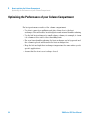
Optimizing the Performance of your Column Compartment
For best performance results of the column compartment:
• Use short connection capillaries and place them close to the heat
exchanger. This will reduce heat dissipation and external band-broadening.
• Use the left heat exchanger for small volume columns, for example, 2–3 mm
i.d. columns at flow rates of less than 200 µl/min.
• For even lower band-broadening, the heat exchanger can be by-passed and
the column is placed well between the heat exchanger fins.
• Keep the left and right heat exchanger temperature the same unless you do
specific applications.
• Assure that the front cover is always closed.
52
1200 Series TCC User Manual
How to optimize the Column Compartment
Using Additional Heater and Cooling Devices
4
Using Additional Heater and Cooling Devices
The optimization, installation, interconnection, and specific settings when
using additional heating and cooling devices are described in the Agilent 1200
Series Rapid Resolution LC System manual (G1312-90300).
1200 Series TCC User Manual
53
4
54
How to optimize the Column Compartment
Using Additional Heater and Cooling Devices
1200 Series TCC User Manual
1200 Series TCC User Manual
5
Troubleshooting and Diagnostics
Overview of the Column Department’s Indicators and Test Functions
56
Status Indicators 57
Power Supply Indicator 57
Module Status Indicator 57
Available Tests depending on User Interfaces
Agilent Diagnostic Software
59
60
Overview about the troubleshooting and diagnostic features.
Agilent Technologies
55
5
Troubleshooting and Diagnostics
Overview of the Column Department’s Indicators and Test Functions
Overview of the Column Department’s Indicators and
Test Functions
Status Indicators
The instrument is provided with two status indicators which indicate the
operational state (prerun, run, and error states) of the instrument. The status
indicators provide a quick visual check of the operation of the instrument.
Error Messages
In the event of an electronic, mechanical or hydraulic failure, the instrument
generates an error message in the user interface. The following pages describe
the meaning of the error messages. For each message, a short description of
the failure, a list of probable causes, and a list of suggested actions to fix the
problem are provided.
Thermostat Diagnostic Test
The thermostat diagnostic test evaluates the heating and cooling efficiency of
the two peltier elements.
Temperature Calibration and Verification
The temperature calibration and verification procedure enables the
instrument temperature to be measured against an external, calibrated
measuring device. Normally, temperature calibration is not required
throughout the lifetime of the instrument. However, in order to comply with
local regulatory requirements, calibration and verification may be required.
The following sections describe these functions in detail.
56
1200 Series TCC User Manual
Troubleshooting and Diagnostics
Status Indicators
5
Status Indicators
Two status indicators are located on the front of the module. The lower left
indicates the power supply status, the upper right indicates the instrument
status.
HiVijh^cY^XVidg
\gZZc$nZaadl$gZY
A^cZedlZghl^iX]
l^i]\gZZca^\]i
Figure 18
Location of Status indicators
Power Supply Indicator
The power supply indicator is integrated into the main power switch. When
the indicator is illuminated (green) the power is ON.
Module Status Indicator
The module status indicator indicates one of four possible instrument
conditions:
• When the status indicator is OFF (and power switch indicator is on), the
instrument is in a prerun condition, and is ready to begin an analysis.
1200 Series TCC User Manual
57
5
Troubleshooting and Diagnostics
Status Indicators
• A green status indicator, indicates the module is performing an analysis
(run mode).
• A yellow indicator indicates a not-ready condition. The module is in a
not-ready state when it is waiting for a specific condition or action to be
completed (for example, immediately after changing a setpoint), or while a
self-test procedure is running.
• An error condition is indicated by a red status indicator. An error condition
indicates the module has detected an internal problem which affects
correct operation of the instrument. Usually, an error condition requires
attention (for example, leak, defective internal components). The error
state is propagated through the system to all connected modules, so the
error might come from a different module. Check the error log of your user
interface for the originating module. For safety reasons, an error condition
always interrupts the analysis.
58
1200 Series TCC User Manual
5
Troubleshooting and Diagnostics
Available Tests depending on User Interfaces
Available Tests depending on User Interfaces
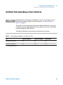
NOTE
Depending on the used interface, the available tests and the screens/reports may vary.
Preferred tool should be the Agilent Lab Advisor Software, see “Agilent Diagnostic
Software” on page 22.
Screenshots used in this document are based on the Agilent ChemStation. In future, the
user interface may not show the Diagnostics/Tests anymore. In this case use the Agilent
Lab Monitor Diagnostic (LMD) Software.
The Agilent ChemStation may not include any maintenance/test functions.
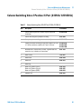
Table 5
Test Functions available vs. User Interface - TCC
Test
Agilent ChemStation
Instant Pilot G4208A
LMD Software
Thermostat Function Test
Yes
No
Yes
Temperature Calibration
Yes
Yes 1
Yes
1
section Maintenance
1200 Series TCC User Manual
59
5
Troubleshooting and Diagnostics
Agilent Diagnostic Software
Agilent Diagnostic Software
The Agilent Diagnostic Software is a standalone product that can be used with
or without data system. Agilent Lab Advisor helps to manage the lab for high
quality chromatographic results and can monitor in real time a single Agilent
LC or all the Agilent GCs and LCs configured on the lab intranet.
Agilent Lab Advisor provides diagnostic capabilities for all Agilent 1200 Series
HPLC modules. This includes tests and calibrations procedures as well as the
different injector steps to perform all the maintenance routines.
Agilent Lab Advisor also allows users to monitor the status of their LC
instruments. The Early Maintenance Feedback (EMF) feature helps to carry
out preventive maintenance. In addition, users can generate a status report for
each individual LC instrument. The tests and diagnostic features as provided
by the Agilent Lab Advisor Software may differ from the descriptions in this
manual. For details refer to the Agilent Lab Advisor help files.
This manual provides lists with the names of Error Messages, Not Ready
messages, and other common issues.
60
1200 Series TCC User Manual
1200 Series TCC User Manual
6
Test Functions
Thermostat Function Test
Pressure Test
62
65
Column Thermostat Temperature Calibration 66
Column Thermostat Temperature Calibration Procedure
Column Thermostat Calibration Problems 69
Installing the Temperature Sensor 69
68
This chapter describes the TCC’s built in test functions.
Agilent Technologies
61
6
Test Functions
Thermostat Function Test
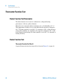
Thermostat Function Test
Heater Function Test Description
The heater function test is used to evaluate the cooling and heating
performance of the two peltier elements.
When the test is started, both heat exchangers are cooled initially to 25 °C.
This temperature is held for 12 seconds, and then the setpoint is changed to
20 °C. The time required to reach 20 °C is a measure of the cooling efficiency
of the peltier elements. At 3.5 minutes, the setpoint is changed to 30 °C, and
both elements begin heating. The time required to reach 30 °C is a measure of
heating efficiency.
Heater Function Test
Thermostat Function Test Result
A typical thermostat function test profile is shown in Figure 19 on page 63.
62
1200 Series TCC User Manual
Test Functions
Thermostat Function Test
6
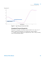
IZbeZgVijgZP8R
G^\]iEZai^ZgZaZbZci
AZ[iEZai^ZgZaZbZci
I^bZPb^cjiZhR
Figure 19
Typical Thermostat Function Test Profile
Evaluating the Thermostat Function Test
During the cooling phase, the Peltier elements should cool at a rate of >2 °C
minute. During the heating phase, the temperature change should be
>3 °C/minute. Defective thermostat components may cause cooling or heating
rates to fall outside these limits.
1200 Series TCC User Manual
63
6
Test Functions
Thermostat Function Test
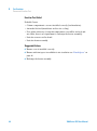
Function Test Failed
Probable Causes
• Column compartment cover not installed correctly (bad insulation).
• Air intake blocked (insufficient air flow for cooling).
• Poor peltier efficiency (if setpoint temperatures can still be reached, and
are stable, there is no requirement to exchange the heater assembly).
• Defective sensors on flex board.
• Defective heater assembly.
Suggested Actions
✔ Ensure cover is installed correctly.
✔ Ensure sufficient space is available for air circulation see “Bench Space” on
page 26.
✔ Exchange the heater assembly.
64
1200 Series TCC User Manual
6
Test Functions
Pressure Test
Pressure Test
For running a pressure test, please refer to the corresponding pump manual.
The pressure test may be used for testing the tightness of a valve installed in
the TCC.
CAUTION
Wrong use of pressure test may damage valve.
The current implementation of the pressure test automatically uses the maximum
pressure generated by the pump used by that system.
➔ Do not use the test for modules having a lower maximum pressure than the pump
as this will damage the valve. For example do not use 400 bar valve in a TCC in
combination with a 600 bar pump.
1200 Series TCC User Manual
65
6
Test Functions
Column Thermostat Temperature Calibration
Column Thermostat Temperature Calibration
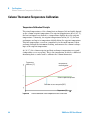
Temperature Calibration Principle
The actual temperatures of the column heat exchangers (left and right) depend
on the column setpoint temperature. For setpoint temperatures above (36 °C),
the heat exchangers are heated to a temperature slightly above the setpoint
temperature. Conversely, for setpoint temperatures below (36 °C), the heat
exchangers are kept at a temperature slightly below the setpoint temperature.
This fine temperature correction compensates for the small amount of heat
exchange through the instrument housing, and ensures the column is always
kept at the setpoint temperature.
At (36 °C), the column setpoint and heat-exchanger temperatures are equal
(temperature cross-over point). This is the temperature at which a calibrated
measuring device can be used to calibrate the column thermostat.
IZbeZgVijgZ
Y^[[ZgZcXZP8R
iZbeZgVijgZVi
bZVhjg^c\ed^ci
8dajbchZied^ciiZbeZgVijgZ
8Va^WgVi^dcViXgdhh"dkZged^ci(+8
IZbeZgVijgZP8R
Figure 20
66
1-Point Calibration at the Temperature Cross-Over Point
1200 Series TCC User Manual
Test Functions
Column Thermostat Temperature Calibration
6
The column thermostat is calibrated correctly when the measured
temperature (using the external measuring device, “Column Thermostat
Temperature Calibration Procedure” on page 68) and the cross-over
temperature (36 °C) of both heat exchangers (left and right) are within a range
of ± 0.5 °C.
1200 Series TCC User Manual
67
6
Test Functions
Column Thermostat Temperature Calibration
Column Thermostat Temperature Calibration Procedure
Tools required
Temperature measuring device (see note below)
Parts required
Description
Calibrated temperature measuring device
NOTE
For the measuring and calibration process Agilent Technologies recommends a
thermometer with 0.1 °C precision. Contact the local Agilent Technologies support
representative for ordering information.
NOTE
The figures in this procedure refer to a specific type of temperature sensor (Heraeus,
Quat340, quartz surface-temperature measurement sensor). Other sensors may require a
different fixing.
1 Install the temperature sensor (“Installing the Temperature Sensor” on
page 69).
2 Select the column-compartment temperature calibration mode in the user
interface.
3 Wait for the temperature to stabilize at the calibration temperature (36 °C).
4 Measure the temperature of the heat exchanger.
5 If the measured temperature deviates by more than ± 0.5 °C from the actual
temperature, enter the measured value in the measured-temperature field
for the left heat exchanger.
6 Install the sensor at the measurement point on the right heat exchanger.
Repeat the calibration procedure for the right heat exchanger.
NOTE
Limits
After calibration, the measured temperature and the calibration temperature should be
within ± 0.5 °C. The maximum deviation which can be adjusted is ± 1.6 °C. If the measured
value and the calibration value differ by more than ± 1.6 °C, this is an indication that a
problem exists, “Column Thermostat Calibration Problems” on page 69.
68
1200 Series TCC User Manual
Test Functions
Column Thermostat Temperature Calibration
6
Column Thermostat Calibration Problems
If the temperature cannot be calibrated, check the following:
• Has the thermostat front cover been closed correctly?
• Is the measuring device functioning correctly, and is calibrated according to
the manufacturers instructions.
Hardware Failures
Probable hardware failures that can lead to a failed calibration procedure are:
• Defective or wrongly calibrated measuring device.
• Defective heater assembly.
• Defective ambient-temperature sensor.
• Defective CCM board.
Installing the Temperature Sensor
Installation of the temperature sensor is required for the temperature
calibration and temperature verification procedures.
NOTE
The figures below refer to a specific type of temperature sensor (Heraeus, Quat340, quartz
surface-temperature measurement sensor). Other sensors may require a different fixing.
1200 Series TCC User Manual
69
6
Test Functions
Column Thermostat Temperature Calibration
1 Remove the front cover.
2 Install the temperature sensor at the measurement
position on the left heat exchanger.
3 Route the sensor wire through the slit in the leak tray.
70
4 Re-install the front cover.
1200 Series TCC User Manual
1200 Series TCC User Manual
7
Maintenance
Introduction to Maintenance and Repair
Warnings and Cautions
Overview of Maintenance
72
73
75
Cleaning the Column Compartment
Changing Column Identification Tags
76
77
Replacing Head Parts of Column Switching Valve (G1316A/G1316B
SL) 79
Adding Heater and Cooling Devices (G1316B SL/G1316C SL Plus)
Correcting Leaks
82
84
Replacing the Column Compartment’s Firmware
Replacing Valve Heads (G1316C SL Plus)
85
86
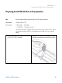
Preparing the G1316C SL Plus for Transportation
89
This chapter describes the maintenance of the TCC.
Agilent Technologies
71
7
Maintenance
Introduction to Maintenance and Repair
Introduction to Maintenance and Repair
Simple Repairs
The column compartment is designed for easy repair. The most frequent
repairs such as change of column and column switching valve head parts can
be done from the front of the column compartment without removing the TCC
from the HPLC stack. These repairs are described in “Maintenance” on
page 71.
Exchanging Internal Parts
Some repairs may require exchange of defective internal parts. Exchange of
these parts requires removing the column compartment from the stack,
removing the covers, and disassembling the column compartment. The
security lever at the power input socket prevents that the column
compartment cover is taken off when line power is still connected.
These repairs are described in the Service Manual.
72
1200 Series TCC User Manual
7
Maintenance
Warnings and Cautions
Warnings and Cautions
WA R N I N G
Module is partially energized when switched off, as long as the power cord is
plugged in.
Risk of stroke and other personal injury. Repair work at the module can lead to
personal injuries, e. g. shock hazard, when the module cover is opened and the
instrument is connected to power.
➔ Never perform any adjustment, maintenance or repair of the module with the top
cover removed and with the power cord plugged in.
➔ The security lever at the power input socket prevents that the module cover is taken
off when line power is still connected. Never plug the power line back in when cover
is removed.
WA R N I N G
Sharp metal edges
Sharp-edged parts of the equipment may cause injuries.
➔ To prevent personal injury, be careful when getting in contact with sharp metal
areas.
WA R N I N G
Toxic and hazardous solvents
The handling of solvents and reagents can hold health risks.
➔ When working with solvents observe appropriate safety procedures (for example,
goggles, safety gloves and protective clothing) as described in the material handling
and safety data sheet supplied by the solvent vendor, especially when toxic or
hazardous solvents are used.
1200 Series TCC User Manual
73
7
Maintenance
Warnings and Cautions
CAUTION
Electronic boards and components are sensitive to electrostatic discharge (ESD).
ESD can damage electronic boards and components.
➔ In order to prevent damage always use ESD protection when handling electronic
boards and components.
CAUTION
Hot heat exchangers
The column compartment has two heat exchanger assemblies that might be hot.
➔ Allow them to cool down before starting repairs.
74
1200 Series TCC User Manual
Maintenance
Overview of Maintenance
7
Overview of Maintenance
The following pages describe maintenance procedures (simple repairs) that
can be done without opening the main cover.
Table 6
Simple Repairs
Procedure
Typical Frequency
“Changing Column
Identification Tags” on page 77
When column performance or new
application requires a change
“Replacing Head Parts of
Column Switching Valve
(G1316A/G1316B SL)” on
page 79
If the valve performance shows
indication of leakage or wear
“Correcting Leaks” on page 84
If a leak has occurred
1200 Series TCC User Manual
Notes
Check for leaks
75
7
Maintenance
Cleaning the Column Compartment
Cleaning the Column Compartment
The column compartment case should be kept clean. Cleaning should be done
with a soft cloth slightly dampened with water or a solution of water and a
mild detergent. Make sure not to let liquid drip into your module.
WA R N I N G
Liquid dripping into the electronic compartment of your module.
Liquid in the module electronics can cause shock hazard and damage the module.
➔ Do not use an exessively damp cloth during cleaning.
➔ Drain all solvent lines before opening any fittings.
76
1200 Series TCC User Manual
7
Maintenance
Changing Column Identification Tags
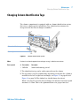
Changing Column Identification Tags
The column compartment is equipped with an column-identification system,
that stores column specific information. Two identification antennas are
incorporated in the heat exchanger assemblies.
6ciZccVh
8dajbc"^YZci^[^XVi^dciV\
8dajbcXa^e
Figure 21
Column-Identification System
When
If column is used on the opposite heat exchanger or a tag is added to a new column.
Parts required
#
Part number
Description
1
5062-8588
Column identification tag, pack of 3
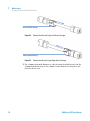
1 The identification tag can be easily removed from the column.
2 The tag needs to be placed differently, depending on whether the column is
installed at the left or right heat exchanger, see Figure 15 on page 49 and
Figure 16 on page 50. The Agilent logo should always be at front.
When correctly placed on the heat exchanger, the distance between tag and
antenna is 1–2 mm. This is the optimum distance for proper function.
1200 Series TCC User Manual
77
7
Maintenance
Changing Column Identification Tags
8dajbc"^YZci^[^XVi^dciV\
Figure 22
Column-Identification Tag for Left Heat Exchanger
8dajbc"^YZci^[^XVi^dciV\
Figure 23
Column-Identification Tag for Right Heat Exchanger
3 For columns with small diameter, a cable tie wrap should be used to fix the
column identification tag to the column. Assure that the tie wrap does not
block the front cover.
78
1200 Series TCC User Manual
Maintenance
Replacing Head Parts of Column Switching Valve (G1316A/G1316B SL)
7
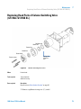
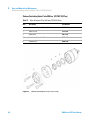
Replacing Head Parts of Column Switching Valve
(G1316A/G1316B SL)
>hdaVi^dchZVa
GdidghZVa
HiVidgg^c\
HiVidg[VXZ
HiVidg]ZVY
Heg^c\h^YZ
h]dlhid
gZVg
HiVidghXgZlh
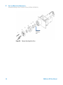
Figure 24
Column Switching Valve Parts
When
If valve leaks.
Tools required
1/4 inch wrench
9/64 inch hex key
Parts required
Description
For parts refer to “Valve Options Overview” on page 92.
1 Remove capillaries from ports 1, 5, and 6.
1200 Series TCC User Manual
79
7
Maintenance
Replacing Head Parts of Column Switching Valve (G1316A/G1316B SL)
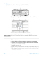
2 Loosen each fixing stator screw two turns at a time. Remove bolts from
head.
3 Remove the stator head and the ceramic stator face.
NOTE
Valve Head, 8 Position/9 Port, High Pressure part number: 5067-4107 has no stator face.
4 Remove the stator ring.
5 Remove the rotor seal (and isolation seal if damaged or contaminated).
6 Install the new isolation seal (if required). Ensure the metal spring inside
the ring faces towards the valve body.
7 Install the new rotor seal.
8 Replace the stator ring. Ensure the stator ring is flush with the valve body.
9 Place the new (if required) ceramic stator face in place on the stator head.
Reinstall the stator head.
80
1200 Series TCC User Manual
7
Maintenance
Replacing Head Parts of Column Switching Valve (G1316A/G1316B SL)
NOTE
Valve Head, 8 Position/9 Port, High Pressure part number: 5067-4107 has no stator face.
10 Insert the stator screws in the stator head. Tighten the screws alternately
two turns at a time until the stator head is secure.
11 Reconnect the pump capillaries to the valve ports. Slide the waste tube into
the waste holder in the leak tray.
CAUTION
Wrong use of pressure test may damage valve.
The current implementation of the pressure test automatically uses the maximum
pressure generated by the pump used by that system.
➔ Do not use the test for modules having a lower maximum pressure than the pump
as this will damage the valve. For example do not use 400 bar valve in a TCC in
combination with a 600 bar pump.
12 Perform a pressure-tightness test to ensure the valve is pressure tight to
400 bar.
1200 Series TCC User Manual
81
7
Maintenance
Adding Heater and Cooling Devices (G1316B SL/G1316C SL Plus)
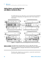
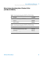
Adding Heater and Cooling Devices
(G1316B SL/G1316C SL Plus)
The addtional heater and cooling devices can be arranged in the G1316B SL in
various locations depending on the application needs . Some examples are
shown below.
Figure 25
NOTE
Arrangements of Heater and Cooling Devices (G1316B SL/G1316C SL Plus)
If the additional heater and cooling devices are used as shown above, the column
identification system cannot be used. If the column identification system is required, fix the
heater and cooling devices in the upper or lower locations or fix them right/left of the
current location.
The heater and cooling devices are mounted on a carrier that can be fitted to
the left and/or right heat exchangers.
82
1200 Series TCC User Manual
Maintenance
Adding Heater and Cooling Devices (G1316B SL/G1316C SL Plus)
7
=ZViZmX]Vc\Zg
8Vgg^Zg[dg]ZViZgdgXddaZg
=ZViZgYZk^XZ
HXgZlYg^kZgIdgmdgEdh^Yg^k
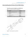
Figure 26
Fixing Heater or Cooling Devices (G1316B SL)
For the heater device inlet capillary choose fittings which are compatible to
your column.
HlV\ZadX`XdbeVi^WaZXdajbch*%+*"))*)!e`d[&%!l^i][ZggjaZh
;^ii^c\hXgZladc\
HlV\ZadX`XdbeVi^WaZXdajbch!gZbdkVWaZ%&%%"'%-+
CjihZVai^\]i
Figure 27
1200 Series TCC User Manual
Fitting type depends on column type
83
7
Maintenance
Correcting Leaks
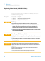
Correcting Leaks
When
If a leakage has occurred at the heat exchanger or at the capillary connections or at the column
switching valve.
Tools required
Tissue, pipette
Wrench 1/4 – 5/16 inch for capillary connections
NOTE
Depending on the column position or the use of additional heat-exchanger assemblies, the
view of Figure 28 on page 84 may vary.
1 Remove the front cover.
2 Use a pipette and tissue to dry the leak sensor area.
3 Observe the capillary connections and the column switching valve for leaks
and correct, if required.
4 Re-install the front cover.
8dajbchl^iX]^c\kVakZ
8dajbc
AZV`hZchdgVhhZbWan
LVhiZ djiaZi
Figure 28
84
Possible Leak Areas
1200 Series TCC User Manual
7
Maintenance
Replacing the Column Compartment’s Firmware
Replacing the Column Compartment’s Firmware
The installation of older firmware might be necessary:
• to keep all systems on the same (validated) revision, or
• if third part control software requires a special version.
To upgrade/downgrade the TCC’s firmware the following steps have to be
performed:
When
If new version solves problems of currently installed version or after exchange of the TCC main board
(CCM) the version on board is older than previous installed one.
Tools required
LAN/RS-232 Firmware Update Tool, or Instant Pilot G4208A or Control Module G1323B
Parts required
Description
Firmware, tools and documentation from Agilent web site
Preparations
Read update documentation provided with the Firmware Update Tool.
1 Download the module’s firmware, the LAN/RS-232 FW Update Tool Version
2.10 or above and the documentation from the Agilent web
http://www.chem.agilent.com/scripts/cag_firmware.asp.
2 Load the firmware into the TCC as described in the documentation.
NOTE
The G1316B SL requires firmware revision A.06.02 or higher (main and resident).
The G1316C SL Plus requires firmware revision A.06.10 or higher (main and resident).
1200 Series TCC User Manual
85
7
Maintenance
Replacing Valve Heads (G1316C SL Plus)
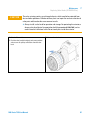
Replacing Valve Heads (G1316C SL Plus)
Several optional valve heads are available for the G1316C, which can be
installed and exchanged easily.
Parts required
CAUTION
#
Part number
Description
1
5067-4107
8pos/9prt valve head high pressure and/or
1
5067-4108
8pos/9prt valve head low pressure
Valve Damage
Using a low pressure valve on the high pressure side can damage the valve.
➔ When using multiple column compartments as part of a method development
solution, make sure that the high pressure valve head is connected to the
autosampler and the low pressure valve head is connected to the detector.
➔ For details, please refer to the Method Development Solution User and Installation
Guide (part number: G4230-90000).
CAUTION
Column Damage or Bias Measurement Results
Switching the valve to a wrong position can damage the column or bias measurement
results.
➔ Fitting the lobe to the groove is essential for making sure the valve is switched to
the correct position.
CAUTION
Valve properties are read from the valve head RFID tag during initialization of the
module. Valve properties will not be updated, if the valve head is replaced while the
module is on.
Selection of valve port positions can fail, if the instrument does not know the
properties of the installed valve.
➔ Always switch off the instrument when replacing the valve head.
86
1200 Series TCC User Manual
Maintenance
Replacing Valve Heads (G1316C SL Plus)
CAUTION
7
The valve actuator contains sensitive optical parts, which need to be protected from
dust and other pollutions. Pollution of these parts can impair the accurate selection of
valve ports and therefore bias measurement results.
➔ Always install a valve head for operation and storage. For protecting the actuator, a
dummy valve head (part of transportation lock kit part number: G1316-67001) can be
used instead of a functional valve. Do not touch parts inside the actuator.
1 Switch off the module.
3 Unscrew the valve head.
2 Push the valve head for bringing it to its outer position
and unscrew all capillary connections from the valve
head.
1200 Series TCC User Manual
87
7
Maintenance
Replacing Valve Heads (G1316C SL Plus)
4 Put the new valve head onto the valve drive such that the 5 Screw the valve head onto the valve drive using the union
lobe fits to the groove.
nut.
6 Install all required capillary connections to the valve head. 7 Push the valve head until it snaps in and stays in the rear
position.
8 Switch on the module.
88
1200 Series TCC User Manual
7
Maintenance
Preparing the G1316C SL Plus for Transportation
Preparing the G1316C SL Plus for Transportation
When
If the Thermostatted Column Compartment SL Plus G1316C shall be transported
Tools required
Screwdriver Pozidriv 1 PT3
Parts required
#
Part number
Description
1
G1316-67001
Transportation Lock Kit
The module has been shipped with transportation locks, which must be used
for transportation protection. A transportation lock kit can be re-ordered
using
1 Remove the valve head as described in “Replacing Valve
Heads (G1316C SL Plus)” on page 86.
1200 Series TCC User Manual
2 Replace the valve head by the transportation valve head.
Bring the transportation valve head to the outer position.
89
7
Maintenance
Preparing the G1316C SL Plus for Transportation
3 Use 4 screws M3x8 (0515-0897) for fixing the lock plate
(G1316-03701) to the heat exchangers in the outer
positions of the plate.
90
4 Use a screw (2680-0128) for fixing the lock plate to the
transportation valve head (G1316-40002) in the central
position of the plate.
1200 Series TCC User Manual
1200 Series TCC User Manual
8
Parts and Materials for Maintenance
Valve Options Overview
92
Heater and Cooling Devices for G1316B SL/G1316C SL Plus
93
Column Switching Valve 2 Position/6 Port (G1316A/G1316B SL)
Column Switching Valve 8 Position-9 Port (G1316C SL Plus)
95
97
Micro Column Switching Valve 2 Postion/6 Port (G1316A/G1316B
SL) 99
Micro Column Switching Valve 2 Position/10 Port (G1316A/G1316B
SL) 100
Accessory Kits 102
G1316A Accessory Kit (Standard) 102
G1316A Accessory Kit (2PS/10PT modules) 103
G1316B SL/G1316C SL Plus Accessory Kit (Standard) 103
G1316B SL/G1316C SL Plus Capillary System Kit 104
G1316B SL Micro Valve Kit 2 Position/10 Port 106
Column Regeneration Kit (G1316A/G1316B SL) 107
Accessories (G1316C SL Plus) 108
Plastic Parts
Leak Parts
109
110
This chapter provides information on parts for maintenance.
Agilent Technologies
91
8
Parts and Materials for Maintenance
Valve Options Overview
Valve Options Overview
This overview gives a summary of the main parts and assemblies. More details
are available with each valve option in this chapter.
Table 7
Valves for G1316A and G1316B SL
Module
Valve Description
Valve
Rotor Seal
Stator
G1316A (#055)
G1316-68700
“Column Switching Valve 2 Position/6 Port
(G1316A/G1316B SL)” on page 95
0101-0920 1
0100-1855 (Vespel)
0100-1854 (Tefzel)
0100-2233 (PEEK)
0100-1851 (Face)
0100-1850 (Head)
0100-1852 (Seal)
G1316A (#056)
“Micro Column Switching Valve 2 Postion/6
Port (G1316A/G1316B SL)” on page 99
0101-1051
0100-2087 (Vespel)
0101-2089
G1316A (#057)
G1316-68709
“Micro Column Switching Valve 2 Position/10
Port (G1316A/G1316B SL)” on page 100
0101-1343 2
0101-1360
0101-1362
G1316B (#055)
“Column Switching Valve 2 Position/6 Port
(G1316A/G1316B SL)” on page 95 (600 bar)
0101-1420
0101-1409
0101-1417
G1316B (#057)
“Micro Column Switching Valve 2 Position/10
Port (G1316A/G1316B SL)” on page 100
(600 bar)
0101-1419
0101-1415
0101-1421
1
re-build kit 0101-1258 includes 3-groove rotor seal, stator face assy, isolation seal, instructions.
2
re-build kit 0101-1360 includes PEEK rotor seal, PEEK stator face, hex key.
Table 8
Valves for G1316C SL Plus
Kit
Kit Description
Valve Head
Rotor Seal
Stator
G4230A
Method Development Valve Kit, low
pressure, includes 8pos/9port valve
5067-4108
5067-41131
5067-4112
G4230B
Method Development Valve Kit, high
pressure, includes 8pos/9port valve
5067-4107
5067-4111
5067-4110
1
92
kit with stator face and rotor seal
1200 Series TCC User Manual
Parts and Materials for Maintenance
Heater and Cooling Devices for G1316B SL/G1316C SL Plus
8
Heater and Cooling Devices for G1316B SL/G1316C SL Plus
The use of these heater and cooling devices is described in Technical Notes or
in the Agilent 1200 Series Rapid Resolution LC System (1200 RRLC System)
manual.
Table 9
Heater and Cooling Devices for G1316B SL
Item
Description
Part Number
Heater long-up (0.12 mm i.d., 1.6 µl internal volume)
(G1316B SL/G1316C SL Plus)
G1316-80002
Part of“G1316B SL/G1316C SL Plus Capillary System Kit” on
page 104.
Heater long-down (0.12 mm i.d., 1.6 µl internal volume)
(G1316B SL/G1316C SL Plus)
G1316-80003
Part of“G1316B SL/G1316C SL Plus Capillary System Kit” on
page 104.
Post-column cooler, (0.12 mm i.d., 1.5 µl internal volume)
(G1316B SL/G1316C SL Plus)
G1316-80004
Part of“G1316B SL/G1316C SL Plus Capillary System Kit” on
page 104.
Carrier for Heater and Cooler
(G1316B SL),
G1316-83200
includes 3 screws SKT-HD-CAP, M3 x 0.5, 12 mm long
0515-1052
Part of “G1316B SL/G1316C SL Plus Capillary System Kit” on
page 104.
1200 Series TCC User Manual
93
8
Parts and Materials for Maintenance
Heater and Cooling Devices for G1316B SL/G1316C SL Plus
Table 10
Consumables (G1316C SL Plus)
Description
Part Number
Column Clip Set, 8 Colors
5042-9918
Carrier for Heat Exchanger G1316C SL Plus
G1316-89200
Fitting Holder Assy, includes following items:
• Fitting Fork
• Fitting Clip
• Screws (Pack of 4)
G1316-68706
A"h]VeZYegZ"Xdajbc]ZViZg
KdajbZ/&#+¥a
bdjciZYdcXVgg^Zg
ide[dgXdajbc&!Wdiidb[dg
Xdajbc'
J"h]VeZYEdhi"XdajbcXddaZg
KdajbZ/&#*¥a
bdjciZYdc8Vgg^Zg
]daZhidViiVX]XVgg^Zg
Figure 29
94
Heater and Cooling Devices for G1316B SL
1200 Series TCC User Manual
Parts and Materials for Maintenance
Column Switching Valve 2 Position/6 Port (G1316A/G1316B SL)
8
Column Switching Valve 2 Position/6 Port (G1316A/G1316B SL)
Table 11
Item
Column Switching Valve 2PS/6PT for G1316A/G1316B SL
Description
Part Number
Column switching valve kit, includes all parts required for
installation
G1353-68700
Column switching valve (complete assembly)
0101-0920
Cover plate (when switching valve is not installed)
G1316-44103
Capillary Kit Column Switching includes two capillaries (0.17mm
i.d., 180 mm) and three capillaries (0.17 mm i.d., 90 mm)
G1316-68708
G1313-87305
G1316-87300
Rhebuild kit for 7750-030 valve, includes: 3-groove rotor seal,
stator face assy, isolation seal, instructions
0101-1258
1
Stator screws
1535-4857
2
Stator Head
0100-1850
3
Stator face
0100-1851
4
Stator ring
5
Rotor seal 3 grooves (Tefzel)
Rotor seal 3 grooves (Vespel)
Rotor seal 3 grooves (PEEK)
0100-1854
0100-1855
0100-2233
6
Isolation seal
0100-1852
1200 Series TCC User Manual
95
8
Parts and Materials for Maintenance
Column Switching Valve 2 Position/6 Port (G1316A/G1316B SL)
+
*
)
(
'
&
Figure 30
96
Heg^c\h^YZ
h]dlhid
gZVg
Column Switching Valve Parts
1200 Series TCC User Manual
Parts and Materials for Maintenance
Column Switching Valve 8 Position-9 Port (G1316C SL Plus)
8
Column Switching Valve 8 Position-9 Port (G1316C SL Plus)
Column Switching Valve Parts High Pressure (G1316C SL Plus)
Table 12
Item
Valve 8 Postion/9 Port, High Pressure (G1316C SL Plus)
Description
Part Number
Valve Head, 8 Position/9 Port, High Pressure
5067-4107
1
Stator Screws
1535-4857
2
Stator Head
5067-4110
3
Rotor Seal High Pressure
5067-4111
4
Isolation Seal
0100-1852
)
(
'
&
Figure 31
1200 Series TCC User Manual
Column Switching Valve Parts (5067-4107)
97
8
Parts and Materials for Maintenance
Column Switching Valve 8 Position-9 Port (G1316C SL Plus)
Column Switching Valve Parts 400 bar (G1316C SL Plus)
Table 13
Item
Valve 8 Postion/9 Port, 400 bar (G1316C SL Plus)
Description
Part Number
Valve Head, 8 Position/9 Port, 400 bar
5067-4108
1
Stator Screws
1535-4857
2
Stator Head
5067-4112
3, 4
Stator Face/Rotor Seal 400 bar
5067-4113
5
Isolation Seal
0100-1852
*
)
(
'
&
Figure 32
98
Column Switching Valve Parts (5067-4108)
1200 Series TCC User Manual
Parts and Materials for Maintenance
Micro Column Switching Valve 2 Postion/6 Port (G1316A/G1316B SL)
8
Micro Column Switching Valve 2 Postion/6 Port
(G1316A/G1316B SL)
Table 14
Item
Description
Part Number
Micro Column Switching Valve 2PS/6PT, 400 bar
0101-1051
Stator face
0100-2089
Rotor seal 3 grooves
0100-2087
Table 15
Item
Micro Column Switching Valve 2PS/6PT for G1316A/B, 400 bar
Micro Column Switching Valve 2PS/6PT for G1316B SL, 600 bar
Description
Part Number
Micro Column Switching Valve 2PS/6PT, 600 bar
0101-1420
Stator, 600 bar
0101-1417
Rotor seal 3 grooves, 600 bar
0101-1409
1200 Series TCC User Manual
99
8
Parts and Materials for Maintenance
Micro Column Switching Valve 2 Position/10 Port (G1316A/G1316B SL)
Micro Column Switching Valve 2 Position/10 Port
(G1316A/G1316B SL)
NOTE
Technical details can be found in the Technical Note that is supplied with the kit.
Table 16
Item
Description
Part Number
2PS/10 PT Valve kit, includes all parts required for installation
G1316-68709
Rebuild kit, includes PEEK rotor seal, PEEK stator face, hex key
0101-1360
2PS/10 PT valve
0101-1343
Rotor seal (Vespel)
0101-1361
Stator face
0101-1362
Capillary kit, see Table 18 on page 100
G1316-68711
Table 17
Item
Table 18
From
Micro Column Switching Valve 2PS/10PT for G1316A/B, 400 bar
Micro Column Switching Valve 2PS/10PT 600 bar for G1316B SL, 600 bar
Description
Part Number
Column Switching Valve 2PS/10PT for µ-LC System, 600 bar
0101-1419
Stator, 600 bar
0101-1421
Rotor seal 5 grooves, 600 bar
0101-1415
Capillary Kit (G1316-68711)
To
ID [mm]
Length [mm]
Qty
Part number
Valve (port 2)
0.17
700
1
5065-9932
Remark
Capillaries
ALS 1
100
1200 Series TCC User Manual
8
Parts and Materials for Maintenance
Micro Column Switching Valve 2 Position/10 Port (G1316A/G1316B SL)
Table 18
Capillary Kit (G1316-68711)
From
To
ID [mm]
Length [mm]
Qty
Part number
Remark
Valve (port 3)
TCC 3 µl (In)
0.17
105
1
5021-1816
TCC 2 3 µl (Out)
Column 1
0.17
105
1
5021-1816
Column 1
Valve (port 6)
0.17
105
1
5021-1816
for long column
Column 1
Valve (port 6)
0.17
200
1
5065-9931
for short column
Valve (port 7)
Detector (In)
0.17
280
1
5021-1818
Valve (port 1)
TCC 6 µl (In)
0.17
105
1
5021-1816
TCC ** 6 µl (Out)
Column 2
0.17
105
1
5021-1816
Column 2
Valve (port 8)
0.17
105
1
5021-1816
for long column
Column 2
Valve (port 8)
0.17
200
1
5065-9931
for short column
Valve (port 5)
Valve (port 10)
0.17
105
1
5021-1816
Regeneration pump
Valve (port 4)
0.25
800
1
5065-9930
Valve (port 9)
Waste
0.6
2000
5062-2463
PTFE
Ferrules, screws, fingertight fittings, etc.
1/16” fittings and ferrules
2
5062-2418
10/pk
fingertight fitting long
1
5062-8541
10/pk
fitting screw long
10
5065-4454
10/pk
fitting screw extra long
10
5065-9967
10/pk
front ferrule
1
5180-4108
10/pk
back ferrule
1
5180-4114
10/pk
1
0890-1763
Plastic tubing cutter
1
8710-1930
Hex key 3/32”
1
8710-2462
Rheotool Socket wrench 2 x 1/4”
1
8710-2391
Peek tubing 1/16”
0.18
1500
1
ALS - Autosampler
2
TCC - Thermostatted Column Compartment (heat exchanger: 3 µl left or 6 µl right)
1200 Series TCC User Manual
101
8
Parts and Materials for Maintenance
Accessory Kits
Accessory Kits
The accessory kits (for G1316A, G1316B SL or G1316C SL Plus) contain
accessories and tools needed for the installation and maintenance.
G1316A Accessory Kit (Standard)
Table 19
Item
1
102
G1316A Accessory Kit (Standard)
Description
Part Number
G1316A Accessory Kit (Standard)
G1316-68705
Column identification tag (blank)
for re-ordering use (pack of 3)
5062-8588
Column clip, qty=2, for re-order use (pack of 6)
5063-6526
Corrugated tubing (to waste), re-order 5 m
5062-2463
CAN cable 0.5 m
5181-1516
Wrench open end 1/4 – 5/16 inch
8710-0510
Wrench open end, 5/16 – 3/8 inch
8710-2409
Capillary column-heat exchanger 90 mm lg, 0.17 i.d. (not
assembled) contains items 2, 3 and 4
G1316-87300
Ferrule front SST, qty=2
1
Ferrule back SST, qty=2
*
Fitting SST, qty=2
*
re-order 5062-2418, pack of 10 each of fittings, front- and back ferrule
1200 Series TCC User Manual
Parts and Materials for Maintenance
Accessory Kits
8
G1316A Accessory Kit (2PS/10PT modules)
Table 20
Item
G1316A Accessory Kit (2PS/10PT modules)
Description
Part Number
G1316A Accessory Kit 2PS/10PT
G1316-68725
Column identification tag (blank)
for re-ordering use (pack of 3)
5062-8588
Column clip, qty=2, for re-order use (pack of 6)
5063-6526
Corrugated tubing (to waste), re-order 5 m
5062-2463
CAN cable 0.5 m
5181-1516
Wrench open end 1/4 – 5/16 inch
8710-0510
Wrench open end, 5/16 – 3/8 inch
8710-2409
PEEK Capillary 280 mm lg, 50 µ i.d., qty=4
G1316-87309
MIC Valve Fitting, qty=2
5022-2186
Column holder for µ-LC columns, qty=2
5001-3702
G1316B SL/G1316C SL Plus Accessory Kit (Standard)
Table 21
Item
Accessory Kit (Standard) G1316B SL and G1316C SL Plus
Description
Part Number
G1316B SL/G1316C SL Plus Accessory Kit (Standard)
G1316-68735
Column identification tag (blank)
for re-ordering use (pack of 3)
5062-8588
Column clip, qty=2, for re-order use (pack of 6)
5063-6526
Corrugated tubing (to waste), re-order 5 m
5062-2463
CAN cable 0.5 m
5181-1516
Wrench open end 1/4 – 5/16 inch
8710-0510
Wrench open end, 5/16 – 3/8 inch
8710-2409
1200 Series TCC User Manual
103
8
Parts and Materials for Maintenance
Accessory Kits
Table 21
Item
1
Accessory Kit (Standard) G1316B SL and G1316C SL Plus
Description
Part Number
Screwdriver Torx TX8
8710-2509
Screwdriver Hexagonal 2.5 mm
5965-0028
Capillary column-heat exchanger 90 mm lg, 0.17 i.d. (not
assembled) contains items 2, 3 and 4
G1316-87300
Capillary column-heat exchanger 115 mm lg, 0.17 i.d. (not
assembled) contains items 2, 3 and 4
G1316-87321
Capillary column-heat exchanger 170 mm lg, 0.17 i.d. (not
assembled) contains items 2, 3 and 4
G1316-87323
Ferrule front SST, qty=2
1
Ferrule back SST, qty=2
*
Fitting SST, qty=2
*
re-order 5062-2418, pack of 10 each of fittings, front- and back ferrule
G1316B SL/G1316C SL Plus Capillary System Kit
G1316B SL/G1316C SL Plus Capillary System Kit
Table 22
G1316B SL Capillary System Kit G1316-68744 (G1316B#060)
Item
Description
Part Number
*
2 Carriers for Heater or Cooling Devices
G1316-83200
*
Heater long-up (0.12 mm i.d., 1.6 µl internal volume)
G1316-80002
*
Heater long-down (0.12 mm i.d., 1.6 µl internal volume)
G1316-80003
*
Post-column cooler (0.12 mm i.d., 1.5 µl internal volume)
G1316-80004
Capillary System Kit, see Table 23 on page 105 for details
G1316-68716
For items * see also “Heater and Cooling Devices for G1316B SL/G1316C SL
Plus” on page 93.
104
1200 Series TCC User Manual
Parts and Materials for Maintenance
Accessory Kits
Table 23
Item
8
Capillary System Kit G1316-68716
Description
Part Number
Seat Capillary 100 mm x 0.12 mm, 0.8 OD
G1367-87303
DAD Heat Exchanger Capillary 310 mm x 0.12 mm
G1315-87339
SST Capillary 340 mm x 0.12 mm, m/m
G1316-87319
SST Capillary 300 mm x 0.12 mm, m/m
G1316-87318
SST Capillary 210 mm x 0.12 mm, m/m
G1316-87317
SST Capillary 170 mm x 0.12 mm, m/m
G1316-87316
SST Capillary 130 mm x 0.12 mm, m/f
G1316-87315
SST Capillary 90 mm x 0.12 mm, m/f
G1316-87314
SST Capillary 70 mm x 0.12 mm, m/f
G1316-87313
SST Capillary 50 mm x 0.12 mm, m/f
G1316-87312
SST Capillary 170 mm x 0.12 mm, m/f
G1316-87327
SST Capillary 500 mm x 0.12 mm, m/m
G1316-87309
SST Capillary 500 mm x 0.12 mm, m/m
G1315-87307
G1316C SL Plus Capillary System Kits
Table 24
G1316C Capillary System Kits
Description1
Part Number
Solvent selection tubing kit, 4 solvents
5067-4601
Method Development Capillary Kit, low dispersion, short column
5067-1595
Method Development Capillary Kit, low dispersion, long column
5067-1596
Method Development Capillary Kit, general purpose
5067-1597
RRHT Selectivity Method Development Kit, 2.1 mm ID
5190-1431
RRHT pH Method Development Kit, 2.1 mm ID
5190-1432
RRHT Selectivity Method Development Kit, 4.6 mm ID
5190-1433
RRHT pH Method Development Kit, 4.6 mm ID
5190-1434
1200 Series TCC User Manual
105
8
Parts and Materials for Maintenance
Accessory Kits
Table 24
G1316C Capillary System Kits
Description1
Part Number
Rapid Resolution Selectivity Method Development Kit
5190-1435
Rapid Resolution pH Method Development Kit
5190-1436
1
for capillary kit contents, please refer to the Method Development Solution User and
Installation Guide (G4230-90000)
G1316B SL Micro Valve Kit 2 Position/10 Port
Table 25
Item
106
G1316B SL Micro Valve Kit 2PS/10PT
Description
Part Number
G1316B SL Micro Valve Kit 2PS/10PT
G1316-68745
Column identification tag (blank)
for re-ordering use (pack of 3)
5062-8588
Column clip, for re-order use (is pack of 6)
5063-6526
Corrugated tubing (to waste), re-order 5 m
5062-2463
Wrench open end 1/4 – 5/16 inch
8710-0510
Wrench open end, 5/16 – 3/8 inch
8710-2409
Screwdriver Torx TX8
8710-2509
Screwdriver Hexagonal 2.5 mm
5965-0028
2 Column holders for µ-LC columns
5001-3702
Column Regeneration Kit for µ-LC columns, see Table 26 on
page 107
G1316-68721
Capillary column-heat exchanger 90 mm lg, 0.17 i.d. (not
assembled) contains items 2, 3 and 4
G1316-87300
Capillary column-heat exchanger 115 mm lg, 0.17 i.d. (not
assembled) contains items 2, 3 and 4
G1316-87321
Capillary column-heat exchanger 170 mm lg, 0.17 i.d. (not
assembled) contains items 2, 3 and 4
G1316-87323
1200 Series TCC User Manual
Parts and Materials for Maintenance
Accessory Kits
8
Column Regeneration Kit (G1316A/G1316B SL)
Refer to Figure 33 on page 108 for connection diagram.
Table 26
Column Regeneration Kit
Description
where used
Column Regeneration Kit
Part Number
G1316-68721
SST Capillary, 700 mm x 0.17 mm, 1/32 - 1/32
column to cell
G1312-87304
SST Capillary, 100 mm x 0.12 mm, 1/32 - 1/32
switching capillary
G1316-27301
SST Capillary, 100 mm x 0.12 mm, male/female 1/32 - 1/16
adapter capillary
G1316-87304
SST Capillary, 340 mm x 0.12 mm, male/female 1/32 - 1/16
WPS to valve
G1316-87305
SST Capillary, 70 mm x 0.12 mm, male/female 1/32 - 1/16, qty=2
valve to heatexchanger
G1316-87306
SST Capillary 50 mm x 0.12 mm, male/female
column to cell
G1316-87312
SST Capillary 70 mm x 0.12 mm, male/female
column to cell
G1316-87313
SST Capillary, 75 mm x 0.12 mm, male/female 1/32 - 1/16
valve to detector
G1316-87326
Seat Capillary, 100 mm x 0.12 mm, qty=2
G1367-87303
PEEK fitting, special for Chip-LC
G4240-43200
Flexible PEEK Tubing, 450 mm x 0.4 mm, =1
1200 Series TCC User Manual
valve to waste
5022-6503
107
8
Parts and Materials for Maintenance
Accessory Kits
Figure 33
Connection Diagram for Column Regeneration
Accessories (G1316C SL Plus)
Table 27
108
Accessories (G1316C SL Plus)
Description
Part Number
Transportation Lock Kit G1316C SL Plus, includes following items:
• Lock Plate
• Screw M4
• Screw M3x8 (pack of 4)
• Spring Washer
• Transportation Valve Head
G1316-67001
1200 Series TCC User Manual
Parts and Materials for Maintenance
Plastic Parts
8
Plastic Parts
Table 28
Plastic Parts
Item
Description
Part Number
2
Front cover G1316A (1200 Series)
G1316-68714
2
Front cover G1316B SL (1200 Series)
G1316-68724
2
Front cover G1316C SL Plus (1200 Series)
G1316-68754
3
Name plate Agilent (1200 Series)
5042-8901
(
'
Figure 34
1200 Series TCC User Manual
Plastic Parts
109
8
Parts and Materials for Maintenance
Leak Parts
Leak Parts
Table 29
Leak Parts G1316A/G1316B SL
Item
Description
Part Number
1
Leak funnel
5041-8388
2
Leak funnel holder
G1316-42300
3
Waste assembly, includes complete Y-tubing assembly with leak
funnel
G1316-60002
Corrugated waste tube (reorder pack), 5 m
5062-2463
&
'
(
Figure 35
110
Leak Parts
1200 Series TCC User Manual
Parts and Materials for Maintenance
Leak Parts
Table 30
Leak Parts G1316C SL Plus
Item
Desription
Part Number
Leak Panel Kit, includes following items:
• Leak Panel Top
• Leak Panel Base
G1316-68722
Leak Tube Kit, includes following items:
• Funnel Holder G1316C SL Plus
• Tubing-flex polyethylene
• Leak Funnel
G1316-67000
Capillary Guide
G1316-42303
1
8
&
Figure 36
1200 Series TCC User Manual
Capillary Guide
111
8
112
Parts and Materials for Maintenance
Leak Parts
1200 Series TCC User Manual
1200 Series TCC User Manual
9
Appendix
Safety Symbols
114
The Waste Electrical and Electronic Equipment Directive
Lithium Batteries Information
Radio Interference
Sound Emission
117
118
119
120
Solvent Information
121
Agilent Technologies on Internet
123
This chapter provides addition information on safety, legal and web.
Agilent Technologies
113
9
Appendix
Safety Symbols
Safety Symbols
Safety Symbols
Table 31
Safety Symbols
Symbol
Description
The apparatus is marked with this symbol when the user should refer to the instruction manual
in order to protect risk of harm to the operator and to protect the apparatus against damage.
Indicates dangerous voltages.
Indicates a protected ground terminal.
Indicates eye damage may result from directly viewing the light produced by the deuterium lamp
used in this product.
The apparatus is marked with this symbol when hot surfaces are available and the user should
not touch it when heated up.
WA R N I N G
A WARNING
alerts you to situations that could cause physical injury or death.
➔ Do not proceed beyond a warning until you have fully understood and met the
indicated conditions.
CAUTION
A CAUTION
alerts you to situations that could cause loss of data, or damage of equipment.
➔ Do not proceed beyond a caution until you have fully understood and met the
indicated conditions.
114
1200 Series TCC User Manual
9
Appendix
Safety Symbols
General Safety Information
The following general safety precautions must be observed during all phases of
operation, service, and repair of this instrument. Failure to comply with these
precautions or with specific warnings elsewhere in this manual violates safety
standards of design, manufacture, and intended use of the instrument. Agilent
Technologies assumes no liability for the customer’s failure to comply with
these requirements.
WA R N I N G
Ensure the proper usage of the equipment.
The protection provided by the equipment may be impaired.
➔ The operator of this instrument is advised to use the equipment in a manner as
specified in this manual.
General
This is a Safety Class I instrument (provided with terminal for protective
earthing) and has been manufactured and tested according to international
safety standards.
Operation
Before applying power, comply with the installation section. Additionally the
following must be observed.
Do not remove instrument covers when operating. Before the instrument is
switched on, all protective earth terminals, extension cords,
auto-transformers, and devices connected to it must be connected to a
protective earth via a ground socket. Any interruption of the protective earth
grounding will cause a potential shock hazard that could result in serious
personal injury. Whenever it is likely that the protection has been impaired,
the instrument must be made inoperative and be secured against any intended
operation.
Make sure that only fuses with the required rated current and of the specified
type (normal blow, time delay, and so on) are used for replacement. The use of
repaired fuses and the short-circuiting of fuse holders must be avoided.
1200 Series TCC User Manual
115
9
Appendix
Safety Symbols
Some adjustments described in the manual, are made with power supplied to
the instrument, and protective covers removed. Energy available at many
points may, if contacted, result in personal injury.
Any adjustment, maintenance, and repair of the opened instrument under
voltage should be avoided whenever possible. When inevitable, this has to be
carried out by a skilled person who is aware of the hazard involved. Do not
attempt internal service or adjustment unless another person, capable of
rendering first aid and resuscitation, is present. Do not replace components
with power cable connected.
Do not operate the instrument in the presence of flammable gases or fumes.
Operation of any electrical instrument in such an environment constitutes a
definite safety hazard.
Do not install substitute parts or make any unauthorized modification to the
instrument.
Capacitors inside the instrument may still be charged, even though the
instrument has been disconnected from its source of supply. Dangerous
voltages, capable of causing serious personal injury, are present in this
instrument. Use extreme caution when handling, testing and adjusting.
When working with solvents please observe appropriate safety procedures
(e.g. goggles, safety gloves and protective clothing) as described in the material
handling and safety data sheet by the solvent vendor, especially when toxic or
hazardous solvents are used.
116
1200 Series TCC User Manual
9
Appendix
The Waste Electrical and Electronic Equipment Directive
The Waste Electrical and Electronic Equipment Directive
Abstract
The Waste Electrical and Electronic Equipment (WEEE) Directive
(2002/96/EC), adopted by EU Commission on 13 February 2003, is
introducing producer responsibility on all electric and electronic appliances
starting with 13 August 2005.
NOTE
This product complies with the WEEE Directive (2002/96/EC) marking requirements. The
affixed label indicates that you must not discard this electrical/electronic product in
domestic household waste.
Product Category:
With reference to the equipment types in the WEEE Directive Annex I, this product is
classed as a “Monitoring and Control Instrumentation” product.
NOTE
Do not dispose off in domestic household waste
To return unwanted products, contact your local Agilent office, or see
www.agilent.com for more information.
1200 Series TCC User Manual
117
9
Appendix
Lithium Batteries Information
Lithium Batteries Information
WA R N I N G
Lithium batteries may not be disposed-off into the domestic waste. Transportation of
discharged Lithium batteries through carriers regulated by IATA/ICAO, ADR, RID,
IMDG is not allowed.
Danger of explosion if battery is incorrectly replaced.
➔ Discharged Lithium batteries shall be disposed off locally according to national
waste disposal regulations for batteries.
➔ Replace only with the same or equivalent type recommended by the equipment
manufacturer.
WA R N I N G
Lithiumbatteri - Eksplosionsfare ved fejlagtig håndtering.
Udskiftning må kun ske med batteri af samme fabrikat og type.
➔ Lever det brugte batteri tilbage til leverandøren.
WA R N I N G
Lithiumbatteri - Eksplosionsfare.
Ved udskiftning benyttes kun batteri som anbefalt av apparatfabrikanten.
➔ Brukt batteri returneres appararleverandoren.
NOTE
118
Bij dit apparaat zijn batterijen geleverd. Wanneer deze leeg zijn, moet u ze niet weggooien
maar inleveren als KCA.
1200 Series TCC User Manual
Appendix
Radio Interference
9
Radio Interference
Cables supplied by Agilent Technoligies are screened to provide opitimized
protection against radio interference. All cables are in compliance with safety
or EMC regulations.
Test and Measurement
If test and measurement equipment is operated with unscreened cables, or
used for measurements on open set-ups, the user has to assure that under
operating conditions the radio interference limits are still met within the
premises.
1200 Series TCC User Manual
119
9
Appendix
Sound Emission
Sound Emission
Manufacturer’s Declaration
This statement is provided to comply with the requirements of the German
Sound Emission Directive of 18 January 1991.
This product has a sound pressure emission (at the operator position) < 70 dB.
• Sound Pressure Lp < 70 dB (A)
• At Operator Position
• Normal Operation
• According to ISO 7779:1988/EN 27779/1991 (Type Test)
120
1200 Series TCC User Manual
9
Appendix
Solvent Information
Solvent Information
Flow Cell
To protect optimal functionality of your flow-cell:
• Avoid the use of alkaline solutions (pH > 9.5) which can attack quartz and
thus impair the optical properties of the flow cell.
• If the flow cell is transported while temperatures are below 5 degree C, it
must be assured that the cell is filled with alcohol.
• Aqueous solvents in the flow cell can built up algae. Therefore do not leave
aqueous solvents sitting in the flow cell. Add a small % of organic solvents
(e.g. acetonitrile or methanol ~5%).
Use of Solvents
Observe the following recommendations on the use of solvents.
• Brown glass ware can avoid growth of algae.
• Small particles can permanently block capillaries and valves. Therefore
always filter solvents through 0.4 µm filters.
• Avoid the use of the following steel-corrosive solvents:
• Solutions of alkali halides and their respective acids (for example,
lithium iodide, potassium chloride, and so on),
• High concentrations of inorganic acids like sulfuric acid and nitric acid,
especially at higher temperatures (if your chromatography method
allows, replace by phosphoric acid or phosphate buffer which are less
corrosive against stainless steel),
• Halogenated solvents or mixtures which form radicals and/or acids, for
example:
2CHCl3 + O2 —> 2COCl2 + 2HCl
This reaction, in which stainless steel probably acts as a catalyst, occurs
quickly with dried chloroform if the drying process removes the
stabilizing alcohol,
1200 Series TCC User Manual
121
9
Appendix
Solvent Information
• Chromatographic grade ethers, which can contain peroxides (for
example, THF, dioxane, di-isopropylether) such ethers should be filtered
through dry aluminium oxide which adsorbs the peroxides,
• Solvents containing strong complexing agents (e.g. EDTA),
• Mixtures of carbon tetrachloride with 2-propanol or THF.
122
1200 Series TCC User Manual
9
Appendix
Agilent Technologies on Internet
Agilent Technologies on Internet
For the latest information on products and services visit our worldwide web
site on the Internet at:
http://www.agilent.com
Select Products/Chemical Analysis
It will provide also the latest firmware of the Agilent 1200 Series modules for
download.
1200 Series TCC User Manual
123
Index
Index
A
D
H
Agilent
Diagnostic Software 22, 60
Lab Advisor Software 22, 60
on internet 123
algae 121, 121
ambient operating temperature 27
ambient non-operating temperature 27
dead volume 28
delivery checklist 34
Diagnostic
software 22, 60
dimensions 27
heaterexchanger
pre-column 30
heating concept 11
humidity 27
B
battery
safety information
bench space 26
118
C
calibration
temperature 56, 66
column switching valve (optional)
description 15
precolumn backflushing 17
column switching valve (optional)
two column selection 16
column clip 50
column identification 13
tag 49
column
changing column and tags 77
cool-down time 28
cooling concept 11
cooling device
post column 30
I
E
electrical connections
descriptions of 18
electronic waste 117
electrostatic discharge (ESD)
environment 26
error messages 56
external measuring device
information 68
74
F
features
GLP 28, 29
instrument layout 21
safety and maintenace 28
flow cell 121
solvent information 121
frequency range 27
function test
failed 64
result 62
G
GLP features
28
installation
bench space 26
capillaries and waste tubings 46
column 45, 45
flow connections 44
module 38
power cords 25
temperature sensor 69
unpacking 34
instrument layout 21
internet 123
introduction
concept of heating and cooling 11
system overview 11
L
Lab Advisor
software 22, 60
leaks, correcting 84
line frequency 27
line voltage 27
lithium batteries 118
N
non-operating altitude 27
non-operating temperature 27
124
1200 Series TCC User Manual
Index
O
S
operating Altitude 27
operating temperature 27
optimization 51
optimizing the performance 52
safety class I 115
safety information
lithium batteries 118
safety
general information 115
standards 27
symbols 114, 114
serial number
information 20
site requirements
environment 26
solvent information 121
solvents 121
sound emission 120
specification
physical 27
specifications 28
stack configuration 35
status indicators 56, 57
system overview 11
P
parts identification
leak panels 110
parts identification
plastics 102
performance
Optimization 51
optimizing 52
specifications and features
physical specifications 27
physical specifications 27
post-column
cooling device 30
power consideration 24
power consumption 27
power cords 25
pre-column
heatexchanger 30
28
R
radio interference 119
repairs
changing the column 77
cleaning the instrument 76
column switching valve parts 79
correcting leaks 84
introduction 72
overview 75
types simple/internal 72
warnings and cautions 72
1200 Series TCC User Manual
T
tag
thermostat function test result 62
thermostat function test 56
troubleshooting
available tests vs interface 59
error messages 56
status indicators 56, 57
U
unpacking 34
User Interfaces
diagnosic tests
59
V
verification
temperature 56
voltage range 27
W
warm-up time 28
waste
electrical and electronic
equipment 117
WEEE directive 117
weight 27
installation 49
temperature verification
principle 69
temperature calibration
description 66
problems 69
procedure 68
temperature verification
external measuring device 68
temperature
range 28
tests
available tests vs interface 59
test
thermostat function test failed 64
125
www.agilent.com
In This Book
This manual contains technical reference
information about the Agilent 1200 Series
thermostatted column compartment.
The manual describes the following:
• introduction and specifications,
• installation,
• using and optimizing,
• troubleshooting and diagnose,
• maintenance and repair,
• parts identification,
• hardware information,
• safety and related information.
©
Agilent Technologies 1995, 1996-2008
Printed in Germany
09/2008
*G1316-90011*
*G1316-90011*
G1316-90011
Agilent Technologies