1
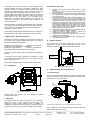
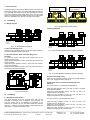
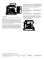
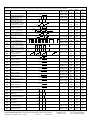
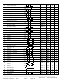
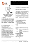
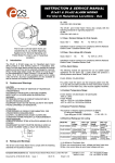
INSTRUCTION & SERVICE MANUAL
D2xS1 ALARM HORN
For Use In Hazardous Locations
3)
Ratings and Markings
3.1 ATEX / IECEx certification
The D2xS1 alarm horn complies with the following standards:EN60079-0:2012 / IEC60079-0: ed. 6.0 (2011-06)
EN60079-15:2010 / IEC60079-15: ed. 4.0 (2010-01)
EN60079-31:2009 / IEC60079-31:2009 ed. 1.0 (corr. 1 2009)
The D2xS1 alarm horn is CE marked for
compliance with the European
Explosive Atmospheres Directive
94/9/EC and the European EMC
Directive 89/336/EEC
1)
Introduction
The D2xS1 is an ATEX, IECEx and UL certified alarm horn
which produces a loud warning signal in a hazardous area.
Sixty-Four first stage alarm sounds can be selected by internal
switches and each one can be externally changed to a second,
third or fourth stage alarm sound. The alarm horn may be used
for Gas applications in Zone 2 / Class I Zone 2 / Class I,
Division 2 as well as for Dust applications in Zone 22 / Class II
Zone 22 / Class II Division 2 / Class III Division 1 & 2. A D2xC1
combined alarm horn & strobe is also available.
2)
The
Type
Examination
Certificate
DEMKO
14ATEX4786493904X / IECEx ULD14.0004X has been issued
by UL. This confirms compliance with the European ATEX
Directive 94/9/EC for Group II, Category 3G/D equipment. The
alarm horn carries the Community Mark and subject to local
codes of practice, may be installed in any of the EEA member
countries. This instruction sheet describes installations which
conform to the current issue of EN60079-14/IEC60079-14
Electrical Installation in Hazardous Areas; EN60079-10-1 / IEC
60079-10-1 Explosive Atmospheres - Classification of Areas.
Explosive Gas Atmospheres; EN60079-10-2 / IEC 60079-10-2
Explosive Atmospheres - Classification of Areas. Explosive
Dust Atmospheres. When designing systems for installation
outside the UK, the local Code of Practice should be consulted.
The D2X Alarm horn is rated as follows:
II 3G
II 3D
Ex nA IIC T4 Gc (Ta -40ºC to +50ºC)
Ex tc IIIC T90ºC Dc (Ta -40ºC to +50ºC)
CE Marking
Warnings
SUITABLE FOR USE IN CLASS II, DIVISION 2, GROUPS A,
B, C AND D HAZARDOUS LOCATIONS
SUITABLE FOR USE IN CLASS II, DIVISION 2, GROUPS E, F
AND G HAZARDOUS LOCATIONS
WARNING: DO NOT OPEN WHEN EXPLOSIVE
ATMOSPHERE IS PRESENT
WARNING – EXPLOSION HAZARD – SUBSTITUTION OF
ANY COMPONENT MAY IMPAIR SUITABILITY FOR CLASS
I, DIVISION 2.
WARNING – EXPLOSION HAZARD – SUBSTITUTION OF
ANY COMPONENTS MAY IMPAIR SUITABILITY FOR CLASS
II, DIVISION 2.
POTENTIAL ELECTROSTATIC CHARGING HAZARD –
CLEAN ONLY WITH A DAMP CLOTH
USE HEAT RESISTANT CABLES AND CABLE GLANDS
(RATED 90ºC OR HIGHER)
EXPLOSION HAZARD. DO NOT REMOVE OR REPLACE
LAMPS, FUSES OR PLUG-IN MODULES UNLESS POWER
HAS BEEN DISCONNECTED OR THE AREA IS KNOWN TO
BE FREE OF IGNITIBLE CONCENTRATIONS OF
FLAMMABLE GASES OR VAPORS.
EXPLOSION HAZARD. DO NOT DISCONNECT WHILE THE
CIRCUIT IS LIVE OR UNLESS THE AREA IS KNOWN TO BE
FREE OF IGNITIBLE CONCENTRATIONS.
Zones, Gas / Dust Groups and Temperature Classification
When connected to an approved system the D2X alarm horn
may be installed in:
Zone 2
explosive gas air mixture not likely to occur in
normal operation, and if it does, it will only exist
for a short time.
Zone 22
explosive dust air mixture not likely to occur in
normal operation, and if it does, it will only exist
for a short time.
May be used with gases in groups:
Group IIA
Group IIB
Group IIC
propane
ethylene
hydrogen / acetylene
Having a temperature classification
(for Gas applications) of:
T1
T2
T3
T4
450ºC
300ºC
200ºC
135ºC
May be used with Dust types:
Group IIIA combustible flyings
Group IIIB non-conductive dust
Group IIIC conductive dust
__________________________________________________________________________________________________________________
European Safety Systems Ltd. Impress House, Mansell Road, Acton, London W3 7QH
[email protected]
Tel: +44 (0)208 743 8880
www.e-2-s.com
Fax: +44 (0)208 740 4200
Document No. D189-00-001-IS Issue: 7
18-06-15
Sheet 1 of 7
Maximum Surface Temperature for Dust Applications:
3.7 Electrical Ratings
90ºC
Part No.
Nominal
Voltage
Nominal
Current
Voltage
Range
D2xS1DC024
24Vdc
313mA
10-30Vdc
D2xS1DC048
48Vdc
181mA
38-58Vdc
D2xS1AC115
115Vac
89mA
D2xS1AC230
230Vac
52mA
3.2 Class / Zone ratings US
The D2xS1 alarm horn complies with the following standards:
ANSI/UL 60079-0-2013
ANSI/UL60079-15-2013
ISA60079-31-2013
The D2X Alarm horn is rated as follows:
Class I, Zone 2
Zone 22
AEx nA IIC T4 Gc (Ta -40ºC to +50°C)
AEx tc IIIC T90°C Dc (Ta -40ºC to +50°C)
115Vac
+/-10%
60Hz
230Vac
+/-10%
50Hz
Max
Current
313mA
@ 24Vdc
218mA
@ 48Vdc
91mA @
126.5Vac
72mA @
253Vac
Installation must be carried out in compliance with the National
Electric Code.
4)
3.3 Class / Zone ratings Canada
Special Condition for safe Use as stated on the Type
Examination Certificate DEMKO 14 ATEX 4786493904X / CoC
IECEx ULD 14.0004X:
Special Conditions for Safe Use
The D2xS1 alarm horn complies with the following standards:
End user shall adhere to the manufacturer’s installation and
instruction when performing housekeeping to avoid the
potential for hazardous electrostatic charger during cleaning,
by using a damp cloth.
CAN/CSA C22.2 No. 60079-0:11
CAN/CSA C22.2 No. 60079-15:12
CAN/CSA C22.2 No. 60079-31:12
The D2XS1 Alarm horn is rated as follows:
Ex nA IIC T4 Gc X (Ta -40ºC to +50°C)
Ex tc IIIC T90°C Dc (Ta -40ºC to +50°C)
Class II Div 2 EFG T5 (Ta -40ºC to +50°C)
Installation must be carried out in compliance with the
Canadian Electric Code
The D2xC1 is not to be mounted with the horn facing upwards
The equipment shall only be used in end use with appropriately
certified cable entry devices and blanking plugs
4.1 Installation
The product must only be installed by suitably qualified
personnel in accordance with the latest issues of the relevant
standards.
3.4 Class / Division Ratings for US and Canada
The D2xS1 alarm horn complies with the following standards:ANSI/ISA 12.12.01-2013
CSA C22.2 No. 213-M1987
CSA C22.2 No. 157-92:2006
The installation of the units must also be in accordance with
any local codes that may apply and should only be carried out
by a competent electrical engineer who has the necessary
training.
The alarm horn is not to be mounted with the horn facing
upwards.
The D2XS1 Alarm horn is rated as follows:
Class I Div 2
ABCD T3C
Class I Div 2
ABCD T4
Class I Div 2
ABCD T4A
Class II Div 2
FG T5
Class II Div 2
FG T6
Class III Div 1 & 2
Ta -40ºC to +70ºC
Ta -40ºC to +65ºC
Ta -40ºC to +50ºC
Ta -40ºC to +50ºC
Ta -40ºC to +45ºC
Ta -40ºC to +50ºC
Installation must be carried out in compliance with the National
Electric Code / Canadian Electric Code
3.5 Ambient Temperature Range:
-40ºC to +70ºC (Class I Div 2 only)
-40ºC to +50ºC
3.6 Ingress Protection Ratings
The product is rated for ingress Protection as follows:
IP rating per EN60529:
IP66
Type rating per UL50E / NEMA250:
4 / 4X / 3R / 13
To maintain the ingress protection rating, the two off M20 cable
entries must be fitted with suitably rated, certified cable entry
and/or blanking devices during installation.
The equipment has not been assessed as a safety-related
device (as referred to by Directive 94/9/EC Annex II, clause
1.5).
The cable entry temperature may exceed +70ºC / the cable
branching point may exceed 80ºC. Therefore suitable heat
resisting cables and cable glands must be used, with a rated
service temperature of at least 90ºC.
To maintain the ingress protection rating and mode of
protection, the M20 x 1.5 cable entries must be fitted with
suitably rated, certified cable glands and/or suitably rated,
certified blanking devices during installation. If a high IP
(Ingress Protection) rating is required then a suitable sealing
washer must be fitted under the cable gland. For use in
explosive gas atmospheres a minimum ingress protection
rating of IP54 must be maintained. For use in explosive dust
atmospheres a minimum ingress protection rating of IP64 must
be maintained.
Only the front cover is to be used for access to the enclosure
for installation, service and maintenance. Once the product is
opened, the Type Rating cannot be maintained anymore
unless a full verification of the gasket material is done and
there is no damage.
__________________________________________________________________________________________________________________
European Safety Systems Ltd. Impress House, Mansell Road, Acton, London W3 7QH
[email protected]
Tel: +44 (0)208 743 8880
www.e-2-s.com
Fax: +44 (0)208 740 4200
Document No. D189-00-001-IS Issue: 7
18-06-15
Sheet 2 of 7
Connections are to be made into the terminal blocks using
solid or stranded wire, sizes 0.5-2.5mm2 / AWG 20-14. Wire
insulation needs to be stripped 6-7mm. Wires may be fitted
securely with crimped ferrules. Terminal screws need to be
tightened down with a tightening torque of 0.56 Nm / 5 Lb-in.
Internal earthing connections should be made to the Internal
earth terminal on the PCBA. The earth conductor should be at
least equal in size and rating to the incoming power
conductors. The internal earth bonding wire connects the
PCBA earth terminal to the internal earth terminal in the
enclosure back box.
5.2 Installation procedure
a)
b)
c)
External earthing connections should be made to the M5 earth
stud, using a ring crimp terminal to secure the earth conductor
to the earth stud. The external earth conductor should be at
least 4mm2 / AWG 11 in size.
d)
Check that the earth bonding wire between the two castings is
secure and the ‘O’ ring seal is in place and in good condition.
e)
4.2 Maintenance, Repair and Overhaul
g)
Maintenance, repair and overhaul of the equipment should only
be carried out by suitably qualified personnel in accordance
with the current relevant standards:
EN60079-19 / IEC60079-19
Explosive atmospheres Equipment repair, overhaul and reclamation
EN 60079-17/ IEC60079-17
Explosive atmospheres Electrical installations inspection and maintenance
f)
6)
Remove Secure the D2xS1 alarm horn to a flat
surface
via the two 9.7 x 6.7mm, 147mm pitch fixing holes in
the mounting feet.
Remove the front of the alarm horn by unscrewing the
four captive cover screws and pulling the front away
from the enclosure.
Fit an M20x1.5 suitably rated, certified cable gland or
conduit entry into the hole in the enclosure and
connect the field wiring to the appropriate alarm horn
terminals as shown in section 9 and fig 8 (DC) or
section 8 fig 5 (AC) of this manual. The power supply
terminals are duplicated so that alarm horns may be
connected in parallel and for DC units only an end of
line monitoring resistor may be fitted. If the second
M20x1.5 entry is not used a suitably rated, certified
stopping plug must always be fitted.
Select the required output tone by positioning the six
switches as shown in Table 1 and Fig 2.
Adjust the internal volume control to provide the
required sound level. (Refer to section 6)
Check that the O-ring seal in the front cover is in good
condition and not damaged.
Replace the front of the alarm horn and tighten the
four captive cover screws.
Volume Control
The output level of the D2xS1 alarm horn can be set by
adjusting the volume control potentiometer (see Fig 2). For
maximum output, set the potentiometer fully clockwise.
Units must not be opened while an explosive atmosphere is
present.
Volume
Control
If opening the unit during maintenance operations a clean
environment must be maintained and any dust layer removed
prior to opening the unit.
Tone Setting
Switches 1-6
(See tone
selection table)
Electrostatic charging hazard - Clean only with a damp cloth
5)
Installation
Fig. 2 Location of field controls
7)
Cable Routing and Tone Selection
7.1 Cable Routing
Due to the compact design of the D2x units, it is important that
the user strips off the outer sheath and biases any cables over
the size of 1mm2 as shown below.
Bias
wires to
the side
Fig. 1 Fixing locations.
D2xS1 alarm horn should only be installed by trained
competent personnel.
5.1 Mounting
The D2xS1 alarm horn may be secured to any flat surface
using the two 9.7 x 6.7mm, 147mm pitch fixing holes. The
enclosure provides IP66 protection and is suitable for
installation in exterior locations providing it is positioned so that
water cannot collect in the horn, and the cable entry is sealed.
Internal
Earth
External
Earth
*Glands and/or stopping plugs to be customer supplied to suit application.
Fig 3. Cables are to be stripped and biased toward side of unit
with allocated spacing as shown.
__________________________________________________________________________________________________________________
European Safety Systems Ltd. Impress House, Mansell Road, Acton, London W3 7QH
[email protected]
Tel: +44 (0)208 743 8880
www.e-2-s.com
Fax: +44 (0)208 740 4200
Document No. D189-00-001-IS Issue: 7
18-06-15
Sheet 3 of 7
7.2 Tone Selection
The D2xS1 alarm horns have 64 different tones. The tones are
selected by operation of the tone setting DIP switches (see Fig.
2) on the PCB. The alarm horns can also be switched to sound
the second, third and fourth stage alarm tones. The tone table
(Table 1) shows the switch positions for the 64 tone and which
tones are available for the second, third and fourth stages.
8)
Wire Links in ‘-‘ positions
for –ve switching
Wire Links in ‘+‘ positions
for +ve switching
AC Wiring
8.1 Wiring Diagram
Fig. 6 Stage Polarity Control settings.
9.2 Wiring Diagrams
STAGE 4 = S2 + S3
(Customer
Supplied)
Fig 4. AC Simplified Block Diagram
8.2 Unit’s First Stage Tones
Stage one (S1) operation: Simply connect the supply voltage to
the L and N supply terminals, (see fig. 5).
8.3 AC Units Second, Third and Fourth Stage Tone
Selection
To select the second, third and fourth stage tones on the
D2xS1 AC alarm horns.
Stage two (S2) operation: Power L and N, link the common (C)
and S2 terminal.
Stage three (S3) operation: Power L and N, link the common
(C) and S3 terminals.
Stage four (S4) operation: Power L and N, link the common (C)
and both the S2 and S3 terminals.
STAGE 4 = S2 + S3
(Customer
Supplied)
Fig. 7a DC Simplified Block Diagram (negative switching)
STAGE 4 = S2 + S3
(Customer
Supplied)
Fig. 7b DC Simplified Block Diagram (positive switching)
9.3 Unit’s First Stage Tones
Stage one (S1) operation: Simply connect the supply voltage to
the + and - supply terminals, (see fig. 8).
9.4 DC Units Second, Third and Fourth Stage Tone
Selection
For units set up for –ve switching (default setting):
Fig. 5 AC Terminals
9)
DC Wiring
9.1 DC Stage Polarity Control
The stage switches of the DC powered D2x units can be
activated via Positive (+ve) or Negative (-ve) switching. All
units are factory set to -ve switching as standard. If +ve
switching is required, the two wire links should be removed
from the ‘-’ positions of the stage polarity control terminals and
fitted to the ‘+‘ positions as shown in fig 6.
Stage two (S2) operation: Power +ve and –ve, link a -ve supply
line to the S2 terminal.
Stage three (S3) operation: Power +ve and –ve, link a -ve
supply line to the S3 terminal.
Stage four (S4) operation: Power +ve and –ve, link a -ve
supply line to both the S2 & S3 terminals.
For units set up for +ve switching (refer to 9.1):
Stage two (S2) operation: Power +ve and –ve, link a +ve
supply line to the S2 terminal.
Stage three (S3) operation: Power +ve and –ve, link a +ve
supply line to the S3 terminal.
Stage four (S4) operation: Power +ve and –ve, link a +ve
supply line to both the S2 & S3 terminals.
__________________________________________________________________________________________________________________
European Safety Systems Ltd. Impress House, Mansell Road, Acton, London W3 7QH
[email protected]
Tel: +44 (0)208 743 8880
www.e-2-s.com
Fax: +44 (0)208 740 4200
Document No. D189-00-001-IS Issue: 7
18-06-15
Sheet 4 of 7
Stage Polarity
Control (See fig.6)
On D2xS1 DC units, dc reverse line monitoring can be used if
required. All DC alarm horns have a blocking diode fitted in
their supply input lines. An end of line monitoring resistor can
be connected across the +ve and –ve terminals. If an end of
line resistor is used it must have the following values:24V DC Alarm horns
Minimum Resistance 3k9 ohms
Minimum Resistance 1k ohms
Minimum wattage 0.5W
Minimum wattage 2.0W
48V DC Alarm horns
Minimum Resistance 15k ohms
Minimum Resistance 3k9 ohms
Fig. 8 DC Terminals
10) Earthing
The unit has both internal and external earth terminals, (please
see fig 3).
Internal earthing connections should be made to the internal
earth terminal on the PCBA, (please see fig 8 for DC, fig 5 for
AC). The earth conductor should be at least equal in size and
rating to the incoming power conductors. The internal earth
bonding wire connects the PCBA earth terminal to the internal
earth terminal in the enclosure back box.
Minimum wattage 0.5W
Minimum wattage 2.0W
The resistor must be connected directly across the +ve and –
ve terminals as shown in the following drawing. Whilst keeping
its leads as short as possible, a spacing of at least 1/16 inch
(1.58mm) must be provided through air and over surfaces
between uninsulated live parts.
End Of Line Resistor
External earth connections should be made to the M5 earth
stud, using a ring crimp terminal to secure the earth conductor
to the earth stud. The external earth conductor should be at
least 4mm2 in size. The external earth crimp ring should be
located between the two M5 plain washers provided and
securely locked down with the M5 spring washer and M5 nut.
Fig. 9 End Of Line Resistor
11) End Of Line Monitoring (DC Units Only)
__________________________________________________________________________________________________________________
European Safety Systems Ltd. Impress House, Mansell Road, Acton, London W3 7QH
[email protected]
Tel: +44 (0)208 743 8880
www.e-2-s.com
Fax: +44 (0)208 740 4200
Document No. D189-00-001-IS Issue: 7
18-06-15
Sheet 5 of 7
Tone Selection – To select the required first stage tone set the tone switches 1 to 6 (see Fig 2) to the tone setting shown in the table below. The table also shows
which 2nd, 3rd and 4th stage tones are available for use with the selected first stage tone if more than one tone output stage is required.
Stage 1
Tone No
1
1000Hz PFEER Toxic Gas
2
1200/500Hz @ 1Hz DIN /
PFEER P.T.A.P.
3
4
5
6
13
1000Hz (1s on, 1s off)x7 + (7s
on, 1s off) IMO Code 1a
420Hz(0.5s on, 0.5s off)x3 +
1s gap ISO 8201 Temporal
Pattern
1000Hz(0.5s on, 0.5s off)x3 +
1s gap ISO 8201 Temporal
Pattern
422/775Hz - (0.85 on, 0.5
off) x3 + 1s gap NFPA Temporal Coded
14
1000/2000Hz @ 1Hz
Singapore
15
300Hz Continuous
16
440Hz Continuous
17
470Hz Continuous
18
500Hz Continuous IMO code
2 (Low)
19
554Hz Continuous
20
660Hz Continuous
21
800Hz IMO code 2 (High)
22
1200Hz Continuous
23
2000Hz Continuous
24
2400Hz Continuous
25
26
440 @0.83Hz (50
cycles/minute) Intermittent
470 @0.9Hz - 1.1s
Intermittent
27
470Hz @5Hz - (5
cycles/second) Intermittent
28
544Hz @ 1.14Hz - 0.875s
Intermittent
29
3
2
44
100000
1
3
44
010000
1
2
44
110000
44
24
1
001000
52
19
1
101000
7
44
1
011000
6
44
1
44
24
35
000100
18
34
1
100100
21
34
1
44
1
8
44
1
8
44
1
8
101100
23
3
35
300Hz
011100
44
24
35
440Hz
111100
44
24
35
470Hz
000010
44
24
35
500Hz
100010
44
24
35
554Hz
010010
64
24
35
660Hz
110010
44
24
35
800Hz
001010
44
24
35
1200Hz
101010
44
24
35
2000Hz
011010
15
3
35
2400Hz
111010
48
20
35
000110
1
44
8
100110
1
44
8
0.1s
010110
1
44
8
0.44s
110110
655Hz @ 0.875Hz
Intermittent
44
24
8
0.57s
001110
1
44
8
30
660Hz @0.28Hz - 1.8sec on,
1.8sec off Intermittent
101110
31
660Hz @3.34Hz - 150mS on,
150mS off Intermittent
44
24
8
011110
30
24
8
123456
1s
1s
500Hz
1000Hz
1s
1s
1600Hz
0.5s
1400Hz
1s
544Hz 0.1s
0.4s
440Hz
1500Hz
1500/500Hz - (0.5s on , 0.5s
off) x3 + 1s gap AS4428
1000Hz (1s on, 1s off)x7 + (7s
on, 1s off) IMO Code 1a
12
000000
1200Hz
544Hz(100mS)/440Hz
(400mS) NF S 32-001
9
11
Stage 4
Tone
(S2 + S3)
1000Hz
1.4KHz-1.6KHz 1s, 1.6KHz1.4KHz 0.5s NF C 48-265
8
10
Stage 3
Tone
(S3)
Switch Settings
Tone Visual
1000Hz @ 0.5Hz(1s on, 1s
off) PFEER Gen. Alarm
500-1500Hz Sweeping 2 sec
on 1 sec off AS4428
500/1200Hz @ 0.26Hz(3.3s
on, 0.5s off) Netherlands NEN 2575
7
Stage 2
Tone
(S2)
Tone Description
500Hz
0.5s 0.5s
0.5s
1.5s
0.5s 0.5s
1500Hz
500Hz
2s
1s
1200Hz
500Hz
1000Hz 1s
1s
1s
1s
1s
1s
1s
1s
1s
1s
420Hz 0.5s
1s
0.5s
1s
0.5s
0.5s
0.5s
7s
010100
1.5s
0.5s
0.5s
7s
1s
1s
0.5s
0.5s
1000Hz 0.5s
111000
0.5s
3.3s
110100
1.5s
775Hz
422Hz
0.85s
0.5s
0.85s
0.85s
0.5s
2000Hz
1000Hz
440Hz
1s
0.6s
0.6s
470Hz 0.55s
0.55s
470Hz
0.1s
470Hz 0.43s
655Hz 0.57s
660Hz
1.8s
1.8s
660Hz 0.15s
0.15s
1.5s
001100
__________________________________________________________________________________________________________________
European Safety Systems Ltd. Impress House, Mansell Road, Acton, London W3 7QH
[email protected]
Tel: +44 (0)208 743 8880
www.e-2-s.com
Fax: +44 (0)208 740 4200
Document No. D189-00-001-IS Issue: 7
18-06-15
Sheet 6 of 7
745Hz
32
33
34
800Hz - 0.25sec on, 1 sec off
Intermittent
44
24
8
000001
53
24
8
800Hz @ 2Hz IMO code 3.a
(High) Intermittent
100001
56
24
8
010001
44
24
8
110001
21
24
8
001001
53
24
8
101001
1
8
19
011001
1
8
19
111001
44
24
19
000101
1
8
19
100101
1
8
19
010101
1
8
19
110101
5
24
19
001101
1
8
19
101101
53
24
19
011101
57
24
19
111101
44
24
12
000011
44
24
12
100011
44
24
12
010011
44
24
12
1s
110011
64
24
12
1s
001011
56
24
12
1s
800Hz 0.25s
0.25s
0.5s
0.5s
1000Hz @ 1Hz Intermittent
2400Hz
36
111110
0.5s
800Hz 0.25s
1000Hz
35
0.5s
745Hz @ 1Hz Intermittent
0.5s
2400Hz @ 1Hz Intermittent
0.5s
2900Hz 0.1s
37
0.1s
2900Hz @ 5Hz Intermittent
518Hz
38
363/518Hz @ 1Hz Alternating
363Hz
0.5s
0.5s
500Hz
39
40
450/500Hz @ 2Hz Alternating
554/440Hz @ 1Hz Alternating
41
554/440Hz @ 0.625Hz
Alternating
42
561/760Hz @0.83Hz (50
cycles/minute) Alternating
43
780/600Hz @ 0.96Hz
Alternating
44
800/1000Hz @ 2Hz
Alternating
45
970/800Hz @ 2Hz Alternating
46
800/1000Hz @ 0.875Hz
Alternating
47
2400/2900Hz @ 2Hz
Alternating
48
500/1200Hz @ 0.3Hz
Sweeping
49
560/1055Hz @ 0.18Hz
Sweeping
50
560/1055Hz @ 3.3Hz
Sweeping
51
600/1250Hz @ 0.125Hz
Sweeping
0.25s
450Hz
554Hz
0.25s
440Hz
0.5s
0.5s
554Hz
440Hz
0.8s
0.8s
760Hz
561Hz
780Hz
0.6s
0.6s
0.52s
0.52s
600Hz
1000Hz
800Hz
970Hz
0.25s
0.25s
0.25s
0.25s
800Hz
1000Hz
0.57s
800Hz 0.57s
2900Hz
0.25s
2400Hz 0.25s
1200Hz
500Hz
1055Hz
3.34s
560Hz
1055Hz
5.47s
560Hz
0.3s
1250Hz
600Hz
8s
1200Hz
52
660/1200Hz @ 1Hz
Sweeping
660Hz
1000Hz
53
800/1000Hz @ 1Hz Sweeping
800Hz
1000Hz
54
800/1000Hz @ 7Hz Sweeping
55
800/1000Hz @ 50Hz
Sweeping
56
2400/2900Hz @ 7Hz
Sweeping
57
2400/2900Hz @ 1Hz
Sweeping
58
2400/2900Hz @ 50Hz
Sweeping
59
2500/3000Hz @ 2Hz
Sweeping
60
2500/3000Hz @ 7.7Hz
Sweeping
61
800Hz Motor Siren
800Hz
1000Hz
0.14s
101011
57
24
12
800Hz
2900Hz
0.02s
011011
54
24
12
0.14s
111011
57
24
12
2400Hz
2900Hz
1s
000111
47
24
12
2400Hz
0.02s
100111
54
24
12
0.5s
010111
44
24
12
0.13s
110111
44
24
12
1.6s
001111
44
24
12
2s
101111
44
24
12
1.7s
011111
44
24
12
111111
44
21
12
2400Hz
2900Hz
3000Hz
2500Hz
3000Hz
2500Hz
800Hz
1200Hz
62
1200Hz Motor Siren
2400Hz
63
2400Hz Motor Siren
1450Hz 0.25s
64
Simulated Bell
0.69ms
__________________________________________________________________________________________________________________
European Safety Systems Ltd. Impress House, Mansell Road, Acton, London W3 7QH
[email protected]
Tel: +44 (0)208 743 8880
www.e-2-s.com
Fax: +44 (0)208 740 4200
Document No. D189-00-001-IS Issue: 7
18-06-15
Sheet 7 of 7