1
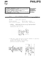
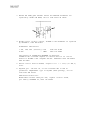
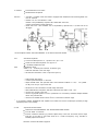
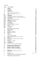
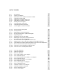
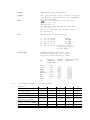
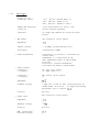
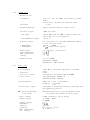
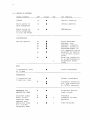
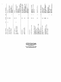
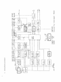
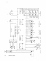
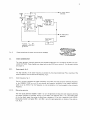
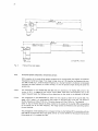
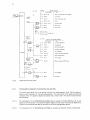
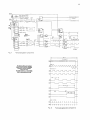
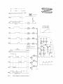
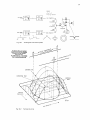
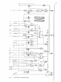
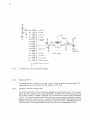
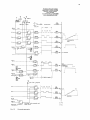
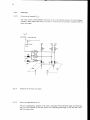
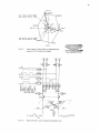
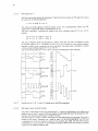
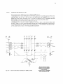
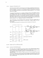
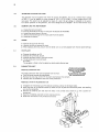
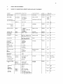
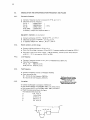
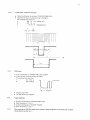
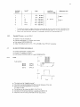
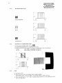
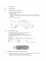
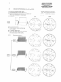
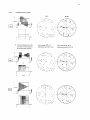
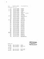
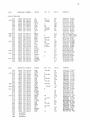
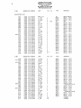
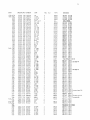
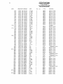
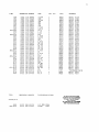
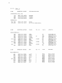
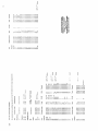
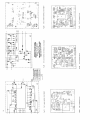
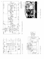
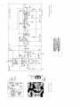
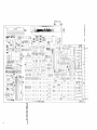
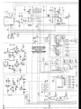
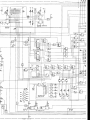
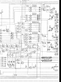
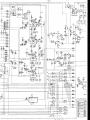
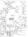
Colour T V pattern generator
PM 5519
9452 055 19003
manual
Service
9499 525 00711
8 7 0 5 0 1 /4
Industrial &
Electro-acoustic Systems
PHILIPS
PHILIPS
Scientific & Analytical Equipment
Test & Measuring Instruments
Industrial Controls
Welding
Industrial Data-processing Systems
840501
Scient ific &
lndustrial
Equipment
Division
TEST AND MEASURING INSTRUMENTS
SGS 3 7
9499 528 0381 1
PM 5519
Colour p a t t e r n g e n e r a t o r
Already published :
L a t e s t i n s t r u c t i o n manual :
SGS 20, SGS 27, SGS 30
9499 525 00711 820801/3/01-10
1. Problem:
BAR-signal i n c o r r e c t ( e . g . one c o l o u r m i s s i n g )
Solution:
I n s e r t c a p a c i t o r 596, 150 pF, 4822 122 31413,
on s o l d e r i n g s i d e of u n i t 1 0 ,
between p i n 8 and 7 of I C 359.
2. Diode BB 113, pos. 402 w i t h i n t h e VHF/UHF m o d u l a t o r i s r e p l a c e d by
2 s i n g l e d i o d e s BB 130, 5322 130 32281.
Because of t h e exchange a c a p a c i t o r 39 p F
p a r a l l e l t o C51 1 has t o be added.
3. Diodes BB 105B, pos. 401/403 w i t h i n t h e VHF/UHF modulator a r e
r e p l a c e d by d i o d e s BB 405B, s e r v i c e code 5322 130 34953.
....
4. Within s e r i e s L0 016
IC351, TCA820 i n t h e modulator i s r e p l a c e d
by TDA820 T, 5322 209 81981.
Additional a l t e r a t i o n s :
C 501, 502, 506
R 602
a l t e r e d t o 1nF
' '
' ' 3K01
5322 122 31998
5322 116 54582
The p i n n i n g of TCA820 and TDA0820T i s d i f f e r e n t .
TCA820 is n o t a v a i l a b l e anymore a t Concern S e r v i c e . I n c a s e of
d e f e c t i v e TCA820 a new complete VHF/UHF modulator 5322 218 64054
must be taken.
5 . P l e a s e c o r r e c t S e r v i c e manual,
lines.
chapter 2.1.2:
V = 3 12 , 5 ( o r 262 , 5 )
6. OQ 5501, pos. 3 5 1 / u n i t 10, i s not a v a i l a b l e due t o end of
p r o d u c t i o n . Replacement t y p e i s OQ 5506 (same p i n n i n g ) , s e r v i c e
code 5322 209 81945.
Additional a l t e r a t i o n s :
Remove NTC- resistor 330E pos 605, r e p l a c e r e s i s t o r 42.2E,
pos. 608 by 53.6E/MR 25, 5322 116 54444.
.
Colour TV pattern generator
Service manual
PHILIPS
Please note
In correspondence concerning this instrument, please quote the type number and serial number as given on the
type plate.
Bitte beachten
Bei Schriftwechsel uber dieses Gerat wird gebeten, die Typennummer und die Geratenummer anzugeben. Diese
befinden sich auf dem Typenschild an der Ruckseite des Gerates.
Note s.v.p.
Dans votre correspondance et dans vos reclamations se rapportant B cet appareil, veuillez toujours indiquer le
numero de type et le numero de serie qui sont marques sur la plaquette de caracteristiques.
lmportant
As the instrument is an electrical apparatus, it may be operated only by trained personnel. Maintenance and repairs
may also be carried out only by qualified personnel.
Wichtig
Da das Gerat ein elektrisches Betriebsmittel ist, darf die Bedienung nur durch eingewiesenes Personal erfolgen.
Wartung und Reparatur durfen nur von geschultem, fach- und sachkundigem Personal durchgefuhrt werden.
lmportant
Comme I'instrument est un equipement electrique, le service doit etre assure par du personnel qualifie. De meme,
I'entretien et les reparations sont confier aux personnes suffisamment qualifiees.
Scientific &
lndust rial
Equipment
Division
850401
TEST AND MEASURING INSTRUMENTS
PM 5519
Colour T V pattern generator
Already published:
Latest service manual:
1. Problem:
Solution:
SGS47
SGS20, SGS27, SGS30, SGS37
9499 525 0071 1, dated 820801/3/01-10
In
-
VIDEO EXT operating mode
the pack porche of the sync pulse is distorted and
the working point of transistor 317 is not okay.
Transistor 317, BC 338, video input amplifier, unit 10 is replaced by BC 337-16,
5322 130 41095 from instruments L 0 18 ... onwards.
- Resistor 730 is paralled by a resistor 56K2.
2. Problem:
Solution:
IC 351 on unit 3, TCA 240, was sometimes not working properly.
Alteration of resistor 604 from 825R to 715R, already inserted from L 0 13 ... onwards.
3. Problem:
Solution:
Diode BA 244, items 402, 404, 406 on unit 2 is not available anymore.
Replaced by diode BA 482, 5322 130 34955, already inserted from L 0 17
4. Problem:
Solution:
The small knobs 5322 414 30027 for memostat, pie-selection unit, can sometimes be damaged.
Please operate the knobs only by hands or by cross-slotted screw-driver.
Don't operate with normal screw driver.
... onwards
2
5. Problem:
Solution:
Sound interference into Video
Residual carrier amplitude
- VHF/UHF modulator 5322 218 64054 is equipped with additional metal screening sheet, from
Dec. 84 onwards.
- Resistor 716, unit 10 is altered to 13K3;
Resistor 716 is paralleled by capacitor 598, OP68, 4822 122 31213;
resistor 722 is altered to 8K25, see figure.
- Diode 434 in the 1 kHz oscillator, unit 10 is paralled by capacitor 597, 1 N, 4822 122 31 175
see figure.
- Some chapters 'CHECK
4.4.1.
AND ADJUSTMENT' of the service manual are revised:
Sub-carrier amplitude
Connect oscilloscope with 10 : 1 probe to TP 5, pin 11/U 1.
Check the sub-carrier amplitude: 2.5 Vpp f0.5 V.
I f necessary readjust with 604
4.6.2.
Residual RF carrier
series L 0 17 ... onwards (new VHF/UHF modulator type)
- select abt. 200 MHz in the VHF range
- set attenuator RF AMPL to max. output level (10 m V ) .
- select WHITE test pattern
- connect spectrum analyzer* to RF OUT
- adjust residual carrier with potmeter 606 of the VHF/UHF-modulator to 10 % ... 12 % (20 dB ...
18 dB), from the sync. tips t o white bar.
- set PM 5519 t o abt. 623 MHz in the UHF-range channel 40.
- select GREYSCALE test pattern and set the attenuator RF AMPL to abt. 1 mV.
- connect CTV receiver to RF OUT
- check that greyscale pattern is correct (modulation not overdriven). Otherwise readjust residual
carrier with potmeter 606.
- check that te residual carrier is within 30 % in the whole VHF/UHF range.
<
*
if no spectrum analyzer available use well adjusted CTV receiver and connect oscilloscope (50 MHz) via high
impedance probe to the IF-stage.
4.1 1.3.
Amplitude RF/soundcarrier
Push button CHECKERBOARD and SOUND MOD CARR ON/OFF.
Turn RF AMPL to maximum.
Connect a selective voltmeter (e.g. Bruell & Kjaer 2007) to RF OUT and check that the amplitude ratio of the video to the sound carrier is 13 - 14 dB at a frequency of e.g. 200 MHz. I f
necessary adjust with 614/U 2.
Alteration concerns also table on page 48.
CONTENTS
SGS 37
SGS 47
1.
1.1.
1.2.
1.3.
1.4.
1.5.
Service information
Service information
GENERAL
Introduction
Technical data
Accessories
Survey of pattern
Operating principle, block diagram, fig. 1
k
CIRCUIT DESCRIPTION with figures 2 - 20
General
Video generator
Raster signals
Horizontal pattern components: vertical lines and bars
Vertical pattern components: horizontal lines, bars and fields
Staircase signals
Circle components
Synthesis of the Black/White test pattern
Colour part
Synthesis of the chroma signals
Chroma and video channels
Sound generator
1 kHz oscillator
Sound input amplifier
Sound carrier oscillator and -modulator
R F part
VH F/UHF modulator
R F pre-selector
Power supply
3.
3.1.
3.2.
3.3.
3.4.
3.5.
3.6.
3.7.
3.8.
INSTALLATION, ACCESS TO PARTS
Safety regulations
Operating position
Earthing
Adjusting to mains voltage
Dismantling the instrument
Knobs
Textplate
Pushbutton unit
CHECK A N D ADJUSTMENT
Survey of adjusting elements and auxiliary equipment
General
Power supply
Modulation- and synchronisation-frequency and pulses
Video signals
R F-check
B L/WH pattern and signals
Colour signals
Colour pattern signals
External video
Sound check, with table and figure for adjustment
5.
5.1.
5.2.
5.3.
5.4.
5.5.
MODIFICATION INTO VARIOUS VERSIONS
Performance details of various versions
Modification of PM 5519 G into PM 5519 I
Modification of PM 5519 G into PM 5519 N
Modification of PM 5519 G into PM 5519 M
Modification of PM 5519 G into PM 5519 MM
6.
6.1.
6.2.
PARTS LIST
Mechanical parts, miscellaneous; with figures 21 - 23
Electrical parts
7.
FIGURES 24 - 35
8.
CODING SYSTEM OF FAILURE REPORTING FOR QUALITY
9.
ADDRESSES FOR SALES AND SERVICE
LIST OF FIGURES
Fig. 1
Fig. 2
Fig. 3
Fig. 4
Fig. 5.1
Fig. 5.2
Fig. 6
Fig. 7
Fig. 8
Fig. 9
Block diagram
Overall circuit diagram
Phase locked loop of master and sub-carrier oscillator
Field and line raster signals
Pulse diagram of OQ5501: NTSC norm
Pulse diagram of OQ5501: CCI R norm
Blanking and control signals
Horizontal pattern components
Field pulse generation components
Control signals for multiburst oscillator
Fig.
Fig.
Fig.
Fig.
Fig.
Fig.
Fig.
10.1
10.2
11
12
13
14
15
Fig.
Fig.
Fig.
Fig.
Fig.
Fig.
16
17
18
19
20.1
20.2
Forming the circle control pulse
Forming the circle
Digital addition of the BL/WH pattern
Summing and scale factor of patterns and signals
Greyscale generation
Generation of the colour sync signal
Phase diagram of the primary and complementarv
colours and of the colour sync signals
Colour bar matrix, control signal and modulator input
Synthesis of the Y, (R-Y) and (B-Y) signals out of the RGB components
Colour difference modulators and phase switches of the colour carrier frequencies
Matrix of the monochrome pattern red, green and blue
Control of the colour modulator for DEM and VCR
Control of the PAL and DEM phase switches
Fig. 21
Fig. 22
Fig. 23
Fig. 24
Fig. 25
Fig. 26
Fig. 27
Fig. 28
Fig. 29
Fig. 30
Fig. 31
Fig. 32
Fig. 33
Fig. 34
Fig. 35
Front view: spare parts
Inside view: spare parts
Back view: spare parts
Unit 1, master oscillator, circuit diagram
Unit 1, component lay-out
Unit 2, sound oscillator and -modulator, circuit diagram
Unit 2, component lay-out
Unit 3, multiburst oscillator, circuit diagram
Unit 3, component lay-out
Unit 11, power supply, circuit diagram
Unit 11, component lay-out
VHF/UHF modulator, circuit diagram
VHF/UH F modulator, components
Unit 10, component lay-out
Unit 10, circuit diagram
GENERAL INFORMATION
1.1.
INTRODUCTION
The multi-system CTV Pattern Generator PM5519 is used for servicing colour
and B/W
TV-sets, monitors, VCR and VLP sets. All test signals allow to de-
termine faults by means of the screen of a TV set or monitor.
The generator provides 12 different test patterns, 7 of them in colour. In
addition, the circle test pattern can be combined with any other test pattern and appears as white or black circle depending on the brightness of
the selected picture.
The composite colour signal with standard number of lines (interlacing) and
standard coupling of line and subcarrier frequency is available at the video output. This video signal of 1 Vpp into a 75
load (fixed position) is
continuously adjustable from 0 to 1.5 Vpp. The amplitude of the chroma signal (including burst) is adjustable in steps of
25% from 0% to 100% of
standard value.
The generator can be adapted to other TV systems.
The amplitude of the RF
riable. This RF
output signal of the generator is continuously va-
signal is modulated with the video signal and the discon-
nectible 1 kHz-modulated sound carrier.
The
carrier frequency of
the generator can be
(bands) and to the intermediate frequency.
tuned to all TV ranges
6 tip-touch buttons are pre-
settable to any frequency within the TV ranges. The preset values are displayed by the individual frequency and range indicator for each selector.
The RF
carrier can be modulated by video and sound signals from external
signal sources via the video input and the audio socket.
For time base synchronisation of an oscilloscope, two signals are available
for line or frame triggering, (comp. sync. and frame).
1.2.
TECHNICAL DATA
Only d a t a w i t h i n d i c a t e d t o l e r a n c e s o r l i m i t s a r e guaranteed;
d a t a w i t h o u t t o l e r a n c e s a r e given o n l y f o r guidance.
1.2.1.
Test signals
-
CIRCLE
w h i t e c i r c l e on grey background, combinable
with a l l t e s t p a t t e r n s
-
CHECKERBOARD
6x8 s q u a r e s
-
DOTS
11x15 ( i n t e r s e c t i o n s of c r o s s h a t c h p a t t e r n )
-
CROSSHATCH
1 1 h o r i z o n t a l and 15 v e r t i c a l l i n e s
-
GREYSCALE combined w i t h
DEFINITION LINES
s t a i r c a s e s i g n a l with 8 i d e n t i c a l s t e p s and
s i n u s o i d a l l i n e - f r e q u e n t m u l t i - b u r s t of 0.8,
1.8, 2.8, 3.8, 4.8 Mhz
-
WHITE
100% w h i t e s i g n a l ( w i t h b u r s t )
- PURITY
r e d , g r e e n and b l u e s i g n a l s e l e c t e d v i a separ a t e b u t t o n s , 75% s a t u r a t i o n ; a l s o complement a r y by c o m b i n a t i o n .
S e c i a l t e s t p a t t e r n of 4 v e r t i c a l b a r s
1 st b a r ( G - Y ) = 0 ;
2rd b a r g r e y (Y)
3th b a r ( R - Y ) NTSC e n c o d e d w i t h PAL b u r s t ;
4
b a r +- (B-Y).
The 2 b a r a n d l o w e r p a r t of t h e s c r e e n are
f o r reference.
- DEM
-
VCR
p a t t e r n with 5 horizontal bars
1/6
1/6
1/6
1/6
2/6
1)
2)
3)
4)
5)
- COLOUR BAR
screen
screen
screen
screen
screen
100% Y
2.8 MHz
3.0 MHz
3.2 MHz
8 - s t e p of L i n e a r l y
increasing saturation w i t h 50% Y
s t a n d a r d chroma s i g n a l w i t h 75%
s a t u r a t i o n ; t h e l o w e r p a r t of t h e
s c r e e n i s u s e d as r e f e r e n c e ( 7 5 % Y )
Bar
White
Yellow
Cyan
Green
Magenta
Red
Blue
Black
1.2.2.
of
of
of
of
of
Relative
luminance
amplitude
Chroma
phase
R e l a t i v e chroma
amplitude
--
0.75
0.67
0.53
0.44
0.31
0.23
0.08
0
p e r f o r m a n c e d e t a i l s of v a r i o u s v e r s i o n s
PM 5519TV s t a n d a r d
Lines p e r
p i c t u r e frame
F i e l d frequency (Hz)
L i n e f r e q u e n c y (Hz)
Chrominance
s u b - c a r r i e r (MHz)
Sound c a r r i e r /
V i s i o n c a r r i e r (MHz)
Sound m o d u l a t i o n
Pre- emphasis (ps)
G
CCIR/PAL
N
CCI R/PAL
M
RTMA/PAL
MM
RTMA/NTSC
62 5
62 5
62 5
525
525
50
15625
50
15625
50
15625
60
15734
60
15734
4.433618
4.433618
3.582056
3.575611
3.579545
4,5
4,5
5,5
I
I
CCIR/PAL
FM
50
6
FM
50
FM
75
FM
75
4,5
FM
75
1.2.3.
Video Part
-Video c a r r i e r
Frequency r a n g e s
38 - 90 Mhz ( I F and band I )
170 - 250 MHz (band III)
470 - 820 MHz (bands I V and V )
the
Range and frequency
selection
6 tip- touch button t o s e l e c t
p r e s e t channel frequency
Indicator
of range and channel f o r each t i p - t o u c h
button
- RF o u t p u t
BNC c o n n e c t o r ( f r o n t p a n e l )
Impedance
Output v o l t a g e
> 10 mVpp ( s y n c h r o n i z i n g l e v e l )
Attenuator
c o n t i n u o u s l y > 6 0dB
-
Video modulation
-
AM n e g a t i v e ( o r p o s i t i v e , s e l e c t a b l e by
solder l i n k ) ;
modulation w i l l t a k e p l a c e on IF.
This modulated s i g n a l i s t h e n mixed
up on RF.
I n t e r n a l o r e x t e r n a l modulation
s e l e c t a b l e by means of push- button
Video o u t p u t s
Connector 1
- Coupling
f o r VCR ( r e a r p a n e l )
DC, mean v a l u e 1.8 V
Connector 2
- Coupling
BNC s o c k e t ( f r o n t p a n e l )
AC
Impedance
-
Nominal v o l t a g e
1 Vpp i n t o a l o a d of 75R ( f i x e d p o s i t i o n of
V I D E O A M P L c o n t r o l ) 0 - 1.5 Vp p, c o n t i n u o u s l y
a d j u s t a b l e , i n t o a l o a d of
Polarity
positive
Video i n p u t
BNC c o n n e c t o r ( f r o n t p a n e l )
Impedance
Nominal v o l t a g e
Polarity
Max. p e r m i s s i b l e
external voltage
positive
1.2.4.
Sound p a r t
-
Sound c a r r i e r
Frequency
Tolerance
- Sound m o d u l a t i o n
F M ( o r AM, s e l e c t a b l e by s o l d e r l i n k )
Internal signal
1 KHz s i n e wave
- FM sweep
(40+-5) kHz w i t h 5.5 MHz; s l i g h t l y d i f f e r e n t
with other c a r r i e r frequencies
(30+-5) %
-
AM m o d u l a t i o n d e p t h
External signal
- Bandwidth
- Preemphasis
- Sound i n p u t
I n p u t impedance
Max. p e r m i s s i b l e
voltage
- Sound s e l e c t o r
1.2.5.
4 . 5 ; 5.5; 6 . 0 ; 6.5 MHz, s e l e c t a b l e by s o l d e r
links;
on d e l i v e r y , a d j u s t e d t o s t a n d a r d v a l u e
<0.2%
0.2 Vrms r e s u l t s i n t h e same m o d u l a t i o n d e p t h
as for lnternal signal
100 H z - 10 KHz
50 p s ( c a n be i n t e r r u p t e d )
D I N connector ( r e a r panel)
0.5
MR
c a r r i e r ON/OFF
m o d u l a t i o n ON/OFF
modulation 1 kHz/external
Sync. p a r t
Line frequency
- Tolerance
- L i n e sync. s i g n a l
- Lines / f i e l d
15625 Hz o r 15734 Hz, a d j u s t e d t o s t a n d a r d
value
0.05%
a c c o r d i n g t o s t a n d a r d s CCIR a n d RTMA
312,5 lines for f line = 15625Hz or
262,5 lines for f line = 15734 Hz
F i e l d frequency
50Hz for f line =1 5 6 2 5 H z o r
6 0 Hz f o r f 15734 Hz
line
-
a c c o r d i n g t o s t a n d a r d s ( w i t h p r e e q u a l i z i n g and
postequalizing pulses)
F i e l d sync. s i g n a l
RRP ( R e c e i v e r Recognit i o n Pulse)
VCR i d e n t i f i c a t i o n I n t h e s y n c h r o n o u s p u l s e ,
s e l e c t a b l e w i t h b u t t o n on f r o n t p a n e l
- Sync. o u t p u t s
2 BNC c o n n e c t o r s ( f r o n t p a n e l )
1 ) CO M P - SYNC
2 ) FRAME
2 4 V
15 k R
negative
DC ( d i g i t a l l e v e l )
+5 V a n d - 1 V
Output s i g n a l
Output v o l t a g e
Impedance
Polarity
Coupling
Max. p e r m i s s i b l e
ext. voltage
642296
1.2.6.
Chroma p a r t
Systems
Subcarrier frequency
1.2.7.
PAL a c c o r d i n g t o TV s y s t e m s I,G o r M ;
(delivered according t o standards)
4.433 6 1 9 MHz f o r PAL G a n d I
3.582 056 MHZ f o r PAL N
3.575 611 MHz f o r PAL M
3 579 5 4 5 MHz f o r NTSC
-6
o
NTSC.
- Tolerance
f5.10
Burst
- Burst phase
according t o standards; contained i n a l l t e s t
patterns
0
135' a n d 225O f o r PAL, 180 for NTSC
Amplitude
b u r s t a n d chroma a m p l i t u d e a d j u s t a b l e i n s t e p s
- Attenuation
0%, 25%, 50%, 75% 100% s e l e c t e d by s e p e r a t e o r
combined p u s h - b u t t o n s
T o l e r a n c e o f chroma a n g l e
23
(+5...+40
C)
0
Power s u p p l y
Mains v o l t a g e
-
Tolerance
110 V, 127 V, 220 V,
switched- over
+10%
240 V e x t e r n a l l y
Mains f r e q u e n c y
- Tolerance
Power c o n s u m p t i o n
1.2.8.
For Service Manuals Contact
MAURITRONTECHNICAL SERVICES
8 Cherry Tree Rd, Chinnor
Oxon OX9 4QY
Tel:- 01844-351694 Fax:- 01844-352554
Email: [email protected]
18 Watt
Environmental conditions
Reference temperature
Nominal o p e r a t i n g
temperature
L i m i t s For s t o r a g e a n d
transportation
0
+23C
+5 t o +40 C
0
-40 t o + 7 0 C
T h i s g e n e r a t o r c o n f o r m s t o VDE 0 4 1 1 , c l a s s I , p r o t e c t i v e e a r t h c o n n e c t i o n .
1.2.9.
Dimensions ( o v e r a l l )
p
Height
Width
Depth
Weight
1.3.
140 mm
305 mm
300 mm
a p p r o x . 4 . 5 kg
ACCESSORIES
Supplied with t h e instrument:
PM 9 5 3 8 C o n n e c t i o n C a b l e BNC - TV c o n n e c t o r , 75 Ohm
O p e r a t i n g manual
Optional:
PM 9539 C o n n e c t i o n C a b l e BNC - impedance t r a n s f o r m e r ,
PM 9 0 7 5 C o n n e c t i o n C a b l e BNC - BNC 75 Ohm
S e r v i c e manual
75
-
300 Ohm