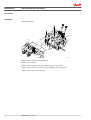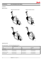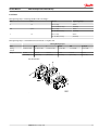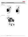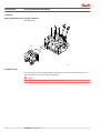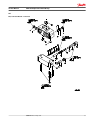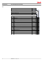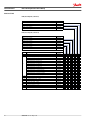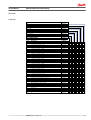
1
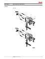
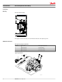
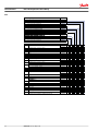
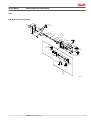
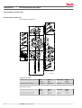
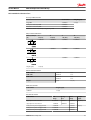
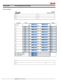
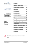
MAKING MODERN LIVING POSSIBLE
Service Manual
Proportional Valve Group
PVG 120
powersolutions.danfoss.com
Service Manual
PVG 120 Proportional Valve Group
Revision history
Table of revisions
2
Date
Changed
Rev
May 2014
Converted to Danfoss layout – DITA CMS, major revision
JA
Jan 2012
Pos. 3 change
ID
Feb 2011
Table on page 35 changed, layout changes - all pages
IC
Feb 2010
Handles on drawings
IA
Jan 2010
Japan location
HC
520L0247 • Rev JA • May 2014
Service Manual
PVG 120 Proportional Valve Group
Contents
PVG 120 service parts exploded view
PVG 120 sectional view
Safety in application
Identification
Installation
PVP
PVLP / PVLA
PVBP, PVBR, PVBC, PVBU
PVM
PVMD and PVH
PVGI
PVEH and PVEO
PVT
PVAS and PVGI
Set of seals
Control system example................................................................................................................................................................ 8
Examples of wiring block diagram..................................................................................................................................... 10
Identification ...................................................................................................................................................................................12
Installation and plug orientation..............................................................................................................................................13
Connection, PVP, Pump Side Module.....................................................................................................................................13
Oil flow direction............................................................................................................................................................................14
Tightening Torques.......................................................................................................................................................................14
PVM, Lever Positions.....................................................................................................................................................................16
Setting of max. flow...................................................................................................................................................................... 16
Pressure Setting..............................................................................................................................................................................17
PVP, LS Relief Valve Pressure Setting.................................................................................................................................17
PVB, LS Relief Valve Pressure Setting.................................................................................................................................17
Option, Oil Flow Direction and Setting of max Flow.........................................................................................................18
Installation of PVE.......................................................................................................................................................................... 18
Bleeding.............................................................................................................................................................................................20
PVPE/PVH relief valves................................................................................................................................................................. 20
PVPH and LS connections........................................................................................................................................................... 21
PVPE technical data.......................................................................................................................................................................21
Connection PVPE............................................................................................................................................................................22
PVP, Pump Side Module.............................................................................................................................................................. 23
PVPD, PVPH, PVPE, Accessories for PVP................................................................................................................................. 25
PVLP / PVLA, Shock and Suction Valve Port A/B................................................................................................................. 27
PVBP, PVBR, PVBC, PVBU Accessories for PVB......................................................................................................................29
PVM, Mechanical Activating Module...................................................................................................................................... 31
PVMD, Cover for PVM and PVH, Hydraulic Activation...................................................................................................... 33
PVGI, Interface for PVG 120 and PVG 32................................................................................................................................ 34
PVEH and PVEO, Electrical Activating Module, ON-OFF...................................................................................................35
PVT, Tank Side Module – Upper Part.......................................................................................................................................37
PVT, Tank Side Module – Lower Part.......................................................................................................................................39
PVGI, Assembly Kit......................................................................................................................................................................... 41
PVAS, Assembly Kit........................................................................................................................................................................41
Asssembly sequence............................................................................................................................................................... 41
Set of Seals .......................................................................................................................................................................................43
PVG 120 Modules Selection Chart
PVG 120 module selection chart.............................................................................................................................................. 44
Order specification
520L0247 • Rev JA • May 2014
3
Service Manual
PVG 120 Proportional Valve Group
Contents
Ordering of modules for oil flow exceeding 180 l/min [47.6 US gal/min].................................................................48
Order Form....................................................................................................................................................................................... 48
Reordering...................................................................................................................................................................................49
4
520L0247 • Rev JA • May 2014
Service Manual
PVG 120 Proportional Valve Group
PVG 120 service parts exploded view
PVG 120 service parts exploded view
13
14
10
3
11
9
3
12
4
8
3
7
5
3
6
4
2
5
1
6
5
6
14
5
520L0247 • Rev JA • May 2014
6
V310144.A
5
Service Manual
PVG 120 Proportional Valve Group
PVG 120 sectional view
PVG 120 sectional view
X-X
10
11
4
12
11
p
ma
T
X
P
A
9
T
P
X
2
A
1
B
13
T
T
P
3
LS
A
P
7
5
1
B
8
B
13
T
T
P
3
6
5
V310100.A
Legend:
6
1 – Main spool
7 – Shock and suction valve PVLP
2 – Pressure adjustment spool in PVP
8 – Suction valve PVLA
3 – Shuttle valve
9 – Orifice, closed center PVP; Plug, open center PVP
4 – Pressure relief valve in PVP
10 – LS connection
5 – Pressure compensator in PVB
11 – Orifice, open center PVP
6 – LS pressure relief valve in PVB
12 – Plug, closed center PVP
520L0247 • Rev JA • May 2014
Service Manual
PVG 120 Proportional Valve Group
Safety in application
All makes and all types of control valves (incl. proportional valves) can fail, thus the necessary protection
against the serious consequences of function failure should always be built into the system. For each
application an assessment should be made for the consequences of pressure failure and uncontrolled or
blocked movements.
To determine the degree of protection that is required to be built into the application, system tools such
an FMEA (Failure Mode and Effect Analysis) and Hazard and Risk Analysis can be used.
FMEA – IEC EN 61508
FMEA (Failure Mode and Effect Analysis) is a tool used for analyzing potential risks. This analytical
technique is utilized to define, identify, and prioritize the elimination or reduction of known and/or
potential failures from a given system before it is released for production. Please refer to IEC FMEA
Standard 61508.
Hazard and risk analysis ISO 12100-1 / 14121
This analysis is a tool used in new applications as it will indicate whether there are special safety
considerations to be met according to the machine directives EN 13849. Dependent on the determined
levels conformity this analysis will detirmine if any extra requirements for the product design,
development process, production process or maintenance, i.e. the complete product life cycle.
W
Warning
All makes/brands and types of directional control valves – inclusive proportional valves – can fail and
cause serious damage. It is therefore important to analyze all aspects of the application.
Because the proportional valves are used in many different operation conditions and applications,
the manufacturer of the application is alone responsible for making the final selection of the products –
and assuring that all performance, safety and warning requirements of the application are met.
The process of choosing the control system – and safety levels – is governed by the machine directives
EN 13849 (Safety related requirements for control systems).
520L0247 • Rev JA • May 2014
7
Service Manual
PVG 120 Proportional Valve Group
Safety in application
Control system example
Example of a control system for manlift using PVE Fault monitoring input signals and signals from external
sensors to ensure the PLUS+1® main controllers correct function of the manlift.
Legend:
1 – Main power supply
2 – Emergency stop/man present switch
3 – HMI/Joystick control
4 – Movement detection sensors
5 – Main controller
6 – PVG control valve
7 – Hydraulic deactivation
8
520L0247 • Rev JA • May 2014
Service Manual
PVG 120 Proportional Valve Group
Safety in application
Electrical block diagram for the above illustration
W
Warning
It is the responsibility of the equipment manufacturer that the control system incorporated in the
machine is declared as being in conformity with the relevant machine directives.
PVG 32 – mainly used in system with fixed displacement pumps:
• PVSK, commonly used in crane application - full flow dump
• PVPX, LS dump to tank
PVG 100 – alternative LS dump or pilot supply disconnect:
• PVPP, pilot oil supply shut off
• External cartridge valve connecting LS pressure or main pressure to tank
PVG 120 – pump disconnect / block for variable pumps:
• PVPE, full flow dump for the PVG 120
• External cartridge valve connecting LS pressure to tank
520L0247 • Rev JA • May 2014
9
Service Manual
PVG 120 Proportional Valve Group
Safety in application
Examples of wiring block diagram
Example of a typical wiring block diagram using PVEH with neutral power off switch and fault monitoring
output for hydraulic deactivation.
A
Emergency
stop
PVE 1
C
Man present
switch
Neutral detection / Supply control
PVEH
with AMP
connector
US
UDC2
1)
signal
≠
neutral
OFF
Delay
B
PVE 2
C
PVEH
Neutral detection / Supply control
with AMP
connector
US
UDC2
1)
signal
≠
neutral
Error
OFF
Delay
B
E1
Error
E2
2) Alarm
logic
Output
OR
3) Memory
AND
high=on
low=off
Fault detection output
D
Hydraulic
deactivation
P301 318
A– Emergency stop / man present switch
B– PVE Fault monitoring signals
C– Neutral signal detection.
D– Hydraulic deactivation
System Control Logic e.g. PLUS+1® for signal monitoring and triggering signal for deactivation of the
hydraulic system.
W
Warning
It is the responsibility of the equipment manufacturer that the control system incorporated in the
machine is declared as being in conformity with the relevant machine directives.
10
520L0247 • Rev JA • May 2014
Service Manual
PVG 120 Proportional Valve Group
Safety in application
Example of fault monitoring for deactivation of the hydraulic system with extra fault inputs using the PVE’s
with DI (Direction Indication) function.
Emergency
Stop
PVE 1
Man present
switch
PVEH-DI
Neutral detection / Supply control
AMP supply
connector
US
UDC2
1)
signal
≠
neutral
OFF
Delay
Error
PVEH-DI
AMP connector
DI-A
DI-B
Fault detection
2)
DI-B
3)
4)
DI-A DI Output Delay Memory
Logic
US
PVE 2
Error
PVEH-DI
Neutral detection / Supply control
AMP supply
connector
US
UDC2
1)
signal
≠
neutral
OFF
Delay
Error
PVEH-DI
AMP connector
DI-A
Fault detection
DI-B
3)
4)
DI-A DI Output Delay Memory
Logic
US
2)
Error
OR
AND
high=on
low=off
Fault detection output
Hydraulic
deactivation
P301 319
System Control Logic e.g. PLUS+1® for signal monitoring and triggering signal for deactivation of the
hydraulic system.
W
Warning
It is the responsibility of the equipment manufacturer that the control system incorporated in the
machine is declared as being in conformity with the relevant machine directives.
520L0247 • Rev JA • May 2014
11
Service Manual
PVG 120 Proportional Valve Group
Identification
Identification
PVG 120 Identification
PVB
PVM
PVT
PVM
PVP
PVEH
G
P
MA
PVEO
S
E
F
C
D
PVH
PVMD
V310156.A
C: PVG – number, week and year of installation
D: PVP – pressure setting
E: PVP – number, week, year and day manufacturing, issue and series No.
F: PVB – A-Port, number, week, year and day manufacturing, issue and series No.
G: PVT – week and year of manufacturing
12
520L0247 • Rev JA • May 2014
Service Manual
PVG 120 Proportional Valve Group
Installation
Installation and plug orientation
60 Nm
[530 lbf•in]
190 [7.48]*
190 [7.48]*
Installation Dimensions
60 Nm
[530 lbf•in]
105 [4.13]
4xM12x18
[4x7/16-14UNCx0.7]
100 [3.94]*
100 [3.94]*
L
V310179.A
* Room for dismantling
Module of PVB
1
2
3
4
5
6
7
8
L mm
168
235
302
369
436
503
570
637
L in
6.61
9.25
11.88
14.53
17.17
19.80
22.44
25.08
Connection, PVP, Pump Side Module
520L0247 • Rev JA • May 2014
13
Service Manual
PVG 120 Proportional Valve Group
Installation
Oil flow direction
Mechanical / electrical actuation
A
P
Mechanical / hydraulic actuation
A
B
B
P
A
B
PB
PA
P
V310169.A
V310163.A
A
P
A
B
B
P
A
B
PA
PB
P
V310162.A
V310170.A
Tightening Torques
Max. tightening torques – Connection Threads Type G (ISO 228/1)
Max. tightening torques
Ports
PA, PB
MA
LS, LX, PP
Sealing thread
G 1/4
G 1/4
G 3/8
With steel washer
35 N•m [310 lbf·in]
40 N•m [350 lbf·in]
60 N•m [530 lbf·in]
With cooper washer
30 N•m [270 lbf·in]
20 N•m [180 lbf·in]
35 N•m [310 lbf·in]
With aluminium washer
30 N•m [270 lbf.in]
30 N•m [270 lbf.in]
40 N•m [350 lbf·in]
With cutting edge
35 N•m [310 lbf.in]
40 N•m [350 lbf.in]
60 N•m [530 lbf·in]
14
520L0247 • Rev JA • May 2014
Service Manual
PVG 120 Proportional Valve Group
Installation
Max. tightening torques – Mounting Threads in SAE J 518c Flanges
Port
Size
Threads
Tightening torque
P
1 in
M12, 18 deep
68 N•m
7/16 - 14 UNC 0.7” deep
[600 lbf·in]
A/B
3/4 in
M10, 17 deep
45 N•m
3/8 - 16 UNC 0.7” deep
[400 lbf·in]
T
1 in
M10, 17 deep
45 N•m
3/8 - 16 UNC 0.7” deep
[400 lbf·in]
Max. tightening torques – UN and UNF Connection Threads – O-ring Boss Port
Max. tightening torques
Ports
P
A/B
T
PA/PB
MA
LS, LX, PP
Sealing
/Thread
1 5/16 in-12 UN
1 1/16 in-12 UN
1 5/16 in-12 UN
½ in-20 UNF
½ in-20 UNF
¾ in-20 UNF
O-ring
160 N•m
120 N•m
160 N•m
30 N•m
30 N•m
60 N•m
[1410 in•lbs]
[1060 in•lbs]
[1410 in•lbs]
[270 in•lbs]
[270 in•lbs]
[530 in•lbs]
Ports identification
520L0247 • Rev JA • May 2014
15
Service Manual
PVG 120 Proportional Valve Group
Installation
PVM, Lever Positions
Base with an angle of 37.5°
Base with an angle of 22.5°
19.5
˚
19.5˚
.5˚
19
19
37.5
˚
.5˚
67
.5˚
.5˚
97
.5˚
127
22.5˚
52
.5˚
82
˚
11
˚
187.5˚
142.5
˚
2.5
157.5˚
.5
172.5˚
V310018.A
V310014.A
Setting of max. flow
Setting of Max. Flow
Q max.A
Q max.
Q max.B
Q max.
B
A
T
LX
PP
3[0.12]
Q max.B
Q max.A
-
8 Nm
[70 lbf in]
+
+
10[0.39]
V310101.A
16
520L0247 • Rev JA • May 2014
Service Manual
PVG 120 Proportional Valve Group
Installation
Pressure Setting
PVP, LS Relief Valve Pressure Setting
3[0.12]
6[0.24]
PVP, LS Relief Valve Setting
P
MA
360° ~ 130 bar
[360° ~ 1900 psi]
3[0.12]
6[0.24]
3[0.12]
LS
3 Nm
[27 lbf•in]
8[0.31]
35 Nm
[310 lbf•in]
V310102.A
PVB, LS Relief Valve Pressure Setting
3[0.12]
6[.24]
PVB, LS Relief Valve Setting
T
PP
3[0.12]
360° ~ 130 bar
[360° ~ 1900 psi]
6[.24]
3[0.12]
LX
3 Nm
[27 lbf•in]
8[0.31]
35 Nm
[510 lbf•in]
V310094.A
520L0247 • Rev JA • May 2014
17
Service Manual
PVG 120 Proportional Valve Group
Installation
Option, Oil Flow Direction and Setting of max Flow
Oil flow direction
A
B
P
A
A
P
B
B
P
PVEH
MA
S
PVEO
V310158.A
Installation of PVE
For security reasons, any replacement of O-rings between valve block 1 and intermediate plate 2 may
only be effected at service shops authorized by Danfoss.
C
Caution
Mixing up PVE series 2 for PVG 120 may lead to self-actuation.
18
520L0247 • Rev JA • May 2014
Service Manual
PVG 120 Proportional Valve Group
Installation
PVEH, PVEO
520L0247 • Rev JA • May 2014
19
Service Manual
PVG 120 Proportional Valve Group
Installation
Bleeding
PVG 120 installed vertically
100[3.94] *
PP
T
LX
190[7.48]
*
V310105.A
If the group is installed vertically, it is recommended to bleed it at the adjusting screws.
PVPE/PVH relief valves
Max. tightening torque for PVPE/PVH
Position
Across flats
Max. tightening torque
1
22 mm [0.87 in]
5 N•m [45 lbf•in]
2
36 mm [1.42 in]
85 N•m [750 lbf•in]
3
36 mm [1.42 in]
85 N•m [750 lbf•in]
Tightening PVPE/PVH
2.5[0.098]
2 Nm
[17.5 lbf•in)
PVPE
PVPH
2
1
LS
P
MA
LS
LS
PVP
V310157.A
20
520L0247 • Rev JA • May 2014
Service Manual
PVG 120 Proportional Valve Group
Installation
PVPH and LS connections
Max. tightening torque for PVPH and LS
Sealing
Threads, DS/ISO 228/1
Max. tightening torque
Steel washer
PVPH: G ¼
40 Nm [350 lbf·in]
LS: G 3∕8
60 Nm [530 lbf·in]
PVPH: G ¼
20 Nm [180 lbf·in]
LS: G 3∕8
35 N•m [310 lbf·in]
PVPH: G ¼
30 N•m [270 lbf·in]
LS: G 3∕8
40 Nm [350 lbf·in]
Cupper washer
Aluminium washer
Cutting edge
PVPH: G ¼
40 Nm [350 lbf·in]
LS: G 3∕8
60 Nm [530 lbf·in]
PVPE technical data
PVPE technical data
Max. operation pressure
350 bar [5085 psi]
Max. pressure drop a an flow of 0.20 l/min. [0.053 US gal/min]
1.2 bar [17 psi]
Oil temperature
(inlet temperature)
Recommended temperature
30 to 60°C [86 to 140°F]
Min. temperature
–30°C [–22°F]
Max. temperature
90°C [194°F]
Max. coil surface temperature
155°C [311°F]
Ambient temperature
–30 to 60°C [–22 to 140°F]
Oil viscosity
Operating range
12 to 75 mm²/s [65 to 347 SUS]
Min. viscosity
4 mm²/s [39 SUS]
Max. viscosity
460 mm²/s [2128 SUS]
Response time for pressure relief to tank
600 ms
Enclosure to. IEC 529
IP 65
Rated voltage
12 V
24 V
Max. permissible deviation from rated supply voltage
± 10 %
± 10 %
Current consumption at
rated voltage
at 22°C [72°F] coil temperature
1.55 A
0.78 A
at 85°C [230°F] coil temperature
1A
0.5 A
at 22°C [72°F] coil temperature
19 W
19 W
at 85°C [230°F] coil temperature
12 W
12 W
520L0247 • Rev JA • May 2014
21
Service Manual
PVG 120 Proportional Valve Group
Installation
Connection PVPE
Installing the wire
When installing the wire remember to connect the built-in diode to the plug pins.
22
520L0247 • Rev JA • May 2014
Service Manual
PVG 120 Proportional Valve Group
PVP
PVP, Pump Side Module
520L0247 • Rev JA • May 2014
23
Service Manual
PVG 120 Proportional Valve Group
PVP
With O-ring Boss port connection 1 5/16 in - 12 UN
Code No.
PVP – closed center incl. PVPD
PVP – open center excl. PVPD, PVPH, PVPE
PVP – open center incl. uprating kit excl. PVPD, PVPH, PVPE
PVP – closed center without relief valve
155G5022
155G5023
155G5028
155G5031
7/16 - 14 UNC
PVP – closed center incl. PVPD
PVP – open center excl. PVPD, PVPH, PVPE
PVP – open center incl. uprating kit excl. PVPD, PVPH, PVPE
PVP – closed center without relief valve
155G5038
155G5037
155G5029
155G5032
× 18 deep
Code No.
PVP – closed center incl. PVPD
PVP – open center excl. PVPD, PVPH, PVPE
PVP – open center incl. uprating kit excl. PVPD, PVPH, PVPE
PVP – closed center without relief valve
155G5020
155G5021
155G5027
155G5030
Item
Code No.
Description
1
Plug
2*
3
4*
5
6
7*
8
9*
10
Bonded seal 14.7 × 1.5 [0.58 × 0.06 in]
Plug
O-ring 30.3 × 2.4 [1.19 × 0.09 in]
Insert incl. item 3, 4
Plug
O-ring 13.3 x 2.4 [0.52 × 0.09 in]
Relief valve incl. pos. 9
Washer 7.0 × 14.0 × 1.5 [0.28 × 0.55 × 0.06 in]
Pump side housing
11
Plug
12*
14
15
16*
Bonded seal 17.4 × 1.5 [0.69 × 0.06 in]
O-ring 16.36 × 2.21 [0.64 × 0.09 in]
Plug
× ∅0.5 [0.2 × 0.02 in]
× ∅0.5 [0.2 × 0.02 in]
Plug
O-ring 33.3 x 2.4 [1.31 × 0.09 in]
17
Spring
13
24
Code No.
18
Spring
19
20
Washer 19.3 × 34.0 × 3.0 [0.76 × 1.34 × 0.12 in]
∅0.5 [0.2 × 0.02 in]
Screw M5 [0.2 in]
22
Spool
23
24*
25
26
27
Plug
Bonded seal 10.35 × 2.0 [0.41 × 0.08 in]
Pin
Name plate
Drive srew
28
Plastic plug
*
**
Set of seals
Uprating set for PVP ( PVB incl. 155G6035 see page 42)
520L0247 • Rev JA • May 2014
631X2036
155L6405
633B9017
155G6212
633B1441
155G5041
155G5325
633B1462
155G8561
684X2367
–
631X2038
631X9716
633B9018
633B0046
681X3019
155G5318
155G5318
155G5314
633B1029**
155G5330
155G5333**
155G5331
155G5334**
155G5317**
155G5318
681X3019
155G5312
155G5321**
070-2741
633B9016
–
155A5021
681Z8055
633X1028
633X0064
155G8501
155G5035
1 1 1 1
1 1 1 1 1
1 1 1 1 1 1 1 1 1
1
1
1
1
1
1
1 1 1
1 1 1
1 1 1
1 1 1
1 1 1
1 1 1
1 1 1
1 1 1
1 1 1 1 1 1 1 1 1
1 1 1 1
1 1 1 1 1
1 1 1 1
1 1 1 1 1
1
1
1 1
1 1
1 1
1 1
1 1 1
1 1 1
1 1 1
1 1 1
1 1
1 1
1
1
1 1
1 1
1
1
1 1 1
1 1 1
1
1
1
1
1 1
1 1
1
1
1 1 1
1 1 1
1 1 1
1 1 1
1 1 1
1 1 1
1 1 1 1 1 1 1 1 1
2 2 2 2 2 2 2 2 2
1 1 1 1 1 1 1 1
1
1 1 1 1 1 1 1 1 1
1 1 1
1 1 1
1
1
1
1 1 1
1 1 1
1 1 1
1 1 1
1 1 1
1 1 1
1 1 1
1
1 1
1 1
1 1 1
1 1 1
1 1
1
1 1
1
1 1 1
1
1
1 1
1
1 1 1
1 1 1
1 1 1
1 1 1
2 2 2
1 1 1
1 1 1
Service Manual
PVG 120 Proportional Valve Group
PVP
PVPD, PVPH, PVPE, Accessories for PVP
520L0247 • Rev JA • May 2014
25
Service Manual
PVG 120 Proportional Valve Group
PVP
Additional Module for PVP Open Center
Type
Code No.
PVPE – extra electrical relief valve
PVPD – Plug
PVPH – extra hydraulic relief valve
Item
1
2
26
155G5052
155G5054
155G5041
155G5061
Description
Code No.
Electrical plug
155G5451
Electrical relief valve incl. item 3, 4, 5
3*
4*
5*
6
7
8
9
10*
11
12
13
× ∅0.5 [0.2 × 0.02 in]
Spool
Plug
O-ring 30 × 3 × 2.4 [1.18 × 0.09 in]
Insert incl. item 9, 10
Plastic plug
Nut
14
15*
16*
17
18
19
20
Bushing
Back-up ring
O-ring 25.3 × 2.4 [1.0 × 0.09 in]
Spool
Cone
Seat
Spring
*
12 V
24 V
O-ring 29.82 × 2.62 [1.18 × 0.10 in]
Back-up ring 27.0 × 2.0 [1.06 × 0.08 in]
O-ring 26.7 × 1.78 [1.05 × 0.07 in]
Spring
Set of seals
520L0247 • Rev JA • May 2014
155G5013
155G5025
633B0069
633B0068
633B0070
155G5332
155G5318
155G5311
631X2040
633B1441
155G5041
633X7018
155G5404
155G5403
155G2316
633B1440
155G5405
155G5406
155B4478
155G3317
155G8527
155G8526
1 1
1
2
1
1
1
1
1
1
2
1
1
1
1
1
2
1
1
1 1
1
2
1
1
1
1
1
1
1
1 1
1
Service Manual
PVG 120 Proportional Valve Group
PVLP / PVLA
PVLP / PVLA, Shock and Suction Valve Port A/B
520L0247 • Rev JA • May 2014
27
Service Manual
PVG 120 Proportional Valve Group
PVLP / PVLA
Type
Code No.
PVLP, pressure setting: 50, 75, 100, 125, 175, 200, 225, 250, 275, 300, 325, 350
,
375, 400 bar [725, 1087, 1450, 1813, 2538, 2900, 3263, 3625, 3988, 4351, 4713,
5076, 5438, 5801 psi]
PVLA
155G1065
Item
Description
Code No.
14
15*
16*
Plug
Back-up ring
Back-up ring
155G1386
633B0014
633B0016
1 1
1 1
1 1
17*
O-ring 20.35 x 1.78 [0.80 × 0.07 in]
PVLP 50 bar [725 psi]
PVLP 75 bar [1087 psi]
PVLP 100 bar [1450 psi]
633B0015
155G0051
155G0076
155G0101
155G0126
155G0151
155G0176
155G0201
155G0226
155G0251
155G0276
155G0301
155G0326
155G0351
155G0376
155G0401
633X0053
155G1387
155G1066
155G8525
1 1
1
1
1
1
1
1
1
1
1
1
1
1
1
1
1
1
1 1
1
1 1
18
19
20
21
*
28
155G0...
PVLP 125 bar [1813 psi]
PVLP 150 bar [2175 psi]
PVLP 175 bar [2538 psi]
PVLP 200 bar [2900 psi]
PVLP 225 bar [3263 psi]
PVLP 250 bar [3625 psi]
PVLP 275 bar [3988 psi]
PVLP 300 bar [4351 psi]
PVLP 325 bar [4713 psi]
PVLP 350 bar [5076 psi]
PVLP 375 bar [5438 psi]
PVLP 400 bar [5801 psi]
Plastic plug to protect cartridge
Spring
PVLA
Set of seals
520L0247 • Rev JA • May 2014
Service Manual
PVG 120 Proportional Valve Group
PVBP, PVBR, PVBC, PVBU
PVBP, PVBR, PVBC, PVBU Accessories for PVB
520L0247 • Rev JA • May 2014
29
Service Manual
PVG 120 Proportional Valve Group
PVBP, PVBR, PVBC, PVBU
Type
PVBU - uprating kit for PVB
PVBR - LSA/B relief valve
PVBP - plug
PVBC - connection for external LS-signal
Item
1
2*
3
4*
5
30
Description
Plug
O-ring 13.3 × 2.4 [0.52 × 0.09 in]
Relief valve incl. item 4
Washer 7.0 × 14.0 × 1.5 [0.28 × 0.55 × 0.06 in]
Plug
Code No.
155G6035
155G6080
155G6081
155G6082
Code No.
155G5325
633B1462
155G8561
684X2367
155G2313
1
1
1
1
1
6*
O-ring 30.3 × 2.4 [1.19 × 0.09 in]
633B1441
1
1
1
1
7*
8*
9**
10
11
12
13
14
15
16
17
*
Back-up ring
O-ring 25.3 × 2.4 [1.0 × 0.09 in]
Adjustment disc.
Spring
Plug
Plug
Bonded seal 14.7 × 1,5 [0.58 × 0.06 in]
Plug
Spring
Plug
Washer 13.5 × 17.5 × 1.5 [0.53 × 0.69 × 0.06 in]
Set of seals
155G2316
633B1440
155G2315
155G2317
155G2322
631X2036
633B9017
155G2323
155G2324
155G2319
684X2120
155G8502
1
1
4
1
1
1
4
1
1
1
1
4
1
1
1
4
520L0247 • Rev JA • May 2014
1
1
1
1
1
1
1
1
1
1
1
Service Manual
PVG 120 Proportional Valve Group
PVM
PVM, Mechanical Activating Module
9
8
8±1 Nm
[70±10 lbf•in]
5[0.20]
3
13
12
11
10
8±1 Nm
[71±9 lbf•in]
7
3[0.12]
4
PVM
6
5
3
10[0.39]
2.5±1 Nm
[22±9 lbf•in]
8±1Nm
[70±9 lbf•in]
4 mm
[0.12 in]
5[0.20]
8± 0.5 Nm
[70±4.5 lbf•in]
2
8±1 Nm
[70±9 lbf•in]
1
8±1 Nm
[70±9 lbf•in]
13 mm
[0.51 in]
6 mm
[0.24 in]
14
V310171.A
520L0247 • Rev JA • May 2014
31
Service Manual
PVG 120 Proportional Valve Group
PVM
Type
PVM with PVMD or PVE
PVM with PVH
Item
1
2
3
4
5
6
Description
Handle, black knob, including nut
Base, including set screw
Screw M6 × 20 [0.24 × 0.78 in]
PVM housing
Seal nut M6
Threaded pin M6 × 25 [0.80 × 0.07 in]
7*
8
9*
10
11
Intermediate plate
O-ring 42.0 × 2.0 [1.65 × 0.08 in]
Spool control pin
Stop
12
Spring
13
Stop
22.5° / 37.5°
22.5° / 37.5°
Code No.
155G3040
155G3050
Code No.
22.5° / 37.5°
681X9266
155L3431
681X8270
1
2
32
Description
Lever, with black knob handle and base
Set of seals
Lever, with red knob handle and base
Handle, black knob, including nut
Base, including set screw
520L0247 • Rev JA • May 2014
1
1
8
1
2
681X0323
2
2
155L3430
155G3301
633B1005
155G3313
155G3314
155G3317
155G3318
155G3315
1
1
1
1
1
1
1
1
1
1
1
Spare Part, Kits Available
Item
14
*
1
1
8
1
2
Code no.
11046724
155G8518
11064640
11077262
11064641
1
1
1
Service Manual
PVG 120 Proportional Valve Group
PVMD and PVH
PVMD, Cover for PVM and PVH, Hydraulic Activation
Type
Code No.
PVM + PVH assy - UNF
PVH assy - BSP.F - thread
155G4021
155G4022
PVMD assy
155G4061
Item
Description
Code No.
17
Screw M6 × 25 [0.80 × 0.07 in]
18
Plastic plug
19
Cover
20*
21*
22
*
O-ring 6.0 × 2.0 [0.24 × 0.78 in]
O-ring 27.0 × 2.0 [1.06 × 0.78 in]
Cover
Set of seals
681X1198
633X7018
633X0018
155G4301
155G4201
633B1460
633B0407
155G4402
155G8505
520L0247 • Rev JA • May 2014
4 4 4
2
2
1
1
4 4 4
1 1 1
1
1 1 1
33
Service Manual
PVG 120 Proportional Valve Group
PVGI
PVGI, Interface for PVG 120 and PVG 32
Type
Code No.
PVGI sddy 1 5/16 in - 12 UN
3/8 in - 16 UNC
155G7033
155G7031
155G7032
Item
Description
Code No.
1
2
3
4
Combination module
O-ring 24.0 × 2.0 [0.94 × 0.08 in]
O-ring 10.0 × 2.0 [0.39 × 0.08 in]
Bonded seal 14.7 × 1.5 [0.58 × 0.06 in]
5
Plug
6
7
Plug
O-ring 30.3 × 2.4 [1.19 × 0.08 in]
8
Plastic plug
–
633B1428
633B1461
633B9017
631X2036
155L6405
631X2040
633B1441
633X1028
633X0019
• Rev IE • Oct 2012
34
520L0247 • Rev JA • May 2014
G 1/4
1/2 - 20 UNF
1
1
2
1
1
1
2
1
1
1
2
1
1
1 1
3 3 3
3 3 3
1
1
1
Service Manual
PVG 120 Proportional Valve Group
PVEH and PVEO
PVEH and PVEO, Electrical Activating Module, ON-OFF
520L0247 • Rev JA • May 2014
35
Service Manual
PVG 120 Proportional Valve Group
PVEH and PVEO
36
520L0247 • Rev JA • May 2014
1
1
1
1
1
1
1
1
1
1
4
1
1
2
1
1
1
4
1
1
2
1
1
1
4
1
1
2
1
1
1
4
1
1
2
1
1
1
1
4
1
1
2
1
1
4
1
1
2
1
1
155G4092
Code No.
984L3156
155U2779
–
–
–
681X9266
633B1148
633B1030
633B1267
633B0407
155G8519
155G4094
Description
El. plug DIN 43650 Black PG 9
Plastic plug
PVEH assy
PVEH assy. with passive fault monitoring
PVEO assy
Screw M6; l = 15 [0.24 in]
O-ring 7 × 2 [0.28 × 0.78 in]
O-ring 15 × 2 [0.59 × 0.78 in]
O-ring 10 × 2 [0.39 × 0.78 in]
O-ring 27 × 2 [1.06 × 0.78 in]
Set of seals
155G4093
AMP
155G4095
4
5*
6*
7*
8*
*
Hirschman
155G4272
Item
1
2
3
12V
24V
12V
24V
Code No.
155G4092
155G4094
155G4093
155G4095
155G4272
155G4274
155G4282
155G4284
155G4274
PVEO
Fault monitoring passive,
11-32V
Connector
Hirschman
AMP
Hirschman
AMP
155G4282
PVEH
Fault monitoring active,
11-32V
155G4284
Type
1
1
1
1
1
4
1
1
2
1
1
4
1
1
2
1
1
Service Manual
PVG 120 Proportional Valve Group
PVT
PVT, Tank Side Module – Upper Part
520L0247 • Rev JA • May 2014
37
Service Manual
PVG 120 Proportional Valve Group
PVT
38
With LX-connection
Code No.
PVT, SAE UNF, mounting thread 3/8 in - 16 UNC
PVT, Boss port connection 1 5/16 in - 12 UN
× 23 deep
155G7025
155G7024
155G7023
Without LX-connection
Code No.
PVT, SAE UNF, mounting thread 3/8 in - 16 UNC
PVT, Boss port connection 1 5/16 in - 12 UN
× 23 deep
155G7022
155G7021
155G7020
Item
Description
1
Plug
2*
3**
4**
5**
6*
7*
Bonded seal 17.4 x 1.5 [0.69 × 0.06 in]
O-ring 16.36 x 2.21 [0.64 × 0.09 in]
Screw M5; l = 6 [0.2 in]
Bonded seal 5.7 x 1.0 [0.22 × 0.04 in]
Plug (item 3 and 4)
O-ring 10.0 x 2.0 [0.39 × 0.08 in]
O-ring 24.0 x 2.0 [0.94 × 0.08 in]
8
Plastic plug
9
*
**
Tank part assy
Set of seals
Used only when load signal is carried to LX-port
520L0247 • Rev JA • May 2014
Code No.
631X2038
631X9716
633B9018
633B0046
681X1925
633B9029
155G8555
633B1461
633B1428
2
633X1028
633X0064
155G8507
155G8555
1
2
2 2
2
2 2
2
2 2
2 2
1 1 1
1 1 1
2 2 2 2 2 2
1 1 1 1 1 1
1 1
1
1
1 1 1 1 1
1 1 1 1 1
1 1 1 1 1
1
1
1
1
Service Manual
PVG 120 Proportional Valve Group
PVT
PVT, Tank Side Module – Lower Part
520L0247 • Rev JA • May 2014
39
Service Manual
PVG 120 Proportional Valve Group
PVT
40
UNC
Code No.
PVT with pilot supply for PVE
PVT without pilot supply for PVE
155G7042
155G7062
BSP.F. thread
Code No.
PVT with pilot supply for PVE
PVT without pilot supply for PVE
155G7040
155G7060
Item
Description
Code No.
10
11
12
Screw M8 x 60 [0.31 × 2.36 in]
Tank part assy
Plug
681X1146
155G7372
13*
14*
15
16*
17
18
19
O-ring 17.5 x 2.4 [0.69 × 0.09 in]
Filter
Plug
O-ring 19.3 x 1.5 [0.76 × 0.06 in]
Stop
Washer 10.0 x 16.0 x 0.5 [0.39 × 0.63 × 0.02 in]
Spring
633B1335
155B4056
155G7373
633B1136
155G7376
684X2094
155G7375
1
1
1
1
1
2
1
1
1
1
1
1
2
1
20
Spool
155G7374
1
1
21
22*
155L1373
633B1813
1
1
1
1
23
24
25
Plug
O-ring 16.0 x 1.5 [0.63 × 0.06 in]
Stop
Washer 7.4 x 11.5 x 1.0 [0.29 × 0.45 × 0.04 in]
Spring
155G7382
684X2547
155G7381
1
2
1
1
2
1
26
*
Ball
Set of seals
689X1040
155G8524
1
1
1
1
Kit for hydraulic activation
155G7041
1
1
520L0247 • Rev JA • May 2014
3 3 3 3
1 1 1 1
1
1
Service Manual
PVG 120 Proportional Valve Group
PVAS and PVGI
PVGI, Assembly Kit
PVAS, Assembly Kit
Asssembly sequence
1.
2.
3.
4.
5.
Mount nut on short thread and torque 10 N•m
Mount seal
Assemble PVG
Mount seal and nut on long thread and torque 10 N•m
When all three stay bolts are mounted, torque full to 80 N•m
W
Warning
Do not reuse stay bolts or loosen torque. The stay bolts are not designed as motor bolts and do not keep
strength when remounted.
520L0247 • Rev JA • May 2014
41
Service Manual
PVG 120 Proportional Valve Group
PVAS and PVGI
PVGI, Assembly Kit (continued)
Type
Code No.
PVGI for 0 basic module
PVGI for 1 basic module
PVGI for 2 basic module
155G8040
155G8041
155G8042
PVGI for 3 basic module
PVGI for 4 basic module
155G8043
155G8044
PVAS, Assembly Kit (continued)
Type
Code No.
PVAS for 1 basic module
PVAS for 2 basic module
PVAS for 3 basic module
PVAS for 4 basic module
PVAS for 5 basic module
PVAS for 6 basic module
PVAS for 7 basic module
PVAS for 8 basic module
155G8031
155G8032
155G8033
155G8034
155G8035
155G8036
155G8037
155G8038
Item
Description
Code No.
1
2* / 2**
Nut
Bonded seal 17.4 x 1.5 [0.69 × 0.06 in]
Stay bolt M12 [0.47]; l = 234 [9.21 in]
155G8312
633B9018
155G8201
4* / 4**
5* / 5**
6* / 6**
7* / 7**
8
9
11
Stay bolt M12 [0.47]; l = 302 [11.89 in]
Stay bolt M12 [0.47]; l = 369 [14.53 in]
Stay bolt M12 [0.47]; l = 436 [17.17 in]
Stay bolt M12 [0.47]; l = 503 [19.80 in]
Stay bolt M12 [0.47]; l = 571 [22.48 in]
Stay bolt M12 [0.47]; l = 638 [25.12 in]
Stay bolt M12 [0.47]; l = 705 [27.76 in]
Stay bolt M12 [0.47]; l = 124.5 [4.90 in]
Stay bolt M12 [0.47]; l = 192.5 [7.58 in] PVGI
Stay bolt M12 [0.47]; l = 260.5 [10.24 in] PVGI
Stay bolt M12 [0.47]; l = 328.5 [12.93 in] PVGI
Stay bolt M12 [0.47]; l = 396.5 [15.61 in] PVGI
Pin
O-ring 33.3 x 2.4 [1.31 × 0.09 in]
O-ring 28.24 x 2.62 [1.118 × 0.10 in]
O-ring 11.91 x 2.62 [0.47 × 0.10 in]
O-ring 5.0 x 2.0 [0.20 × 0.08 in]
O-ring 16.0 x 2.5 [0.63 × 0.10 in]
O-ring 10.0 x 2.5 [0.39 × 0.10 in]
155G8202
155G8203
155G8204
155G8205
155G8206
155G8207
155G8208
155G8330
155G8331
155G8332
155G8333
155G8334
682L2006
633B1029
3
18 16 14 12 10 8 6 4 10 8 6 4 2
18 16 14 12 10 8 6 4 10 8 6 4 2
633B1956
633B1955
9 8 7 6 5 4 3 2 5 4 3 2 1
18 16 14 12 10 8 6 4 10 8 6 4 2
633B1809
633B1817
2 2 2 2 2
4 4 4 4 4
*
**
Set of seals for additionel sections
633B0120
155G8522
155G8523
1 1 1 1 1
1 1 1 1 1 1 1 1 1 1 1 1
7 6 5 4 3 2 1
3 2 1
3
42
520L0247 • Rev JA • May 2014
3 3 3 3 3 3 3 3 3 3 3 3 3
6 6 6 6 6 6 6 6 6 6 6 6 6
3
3
3
3
3
3
3
3
3
3
3
3
Service Manual
PVG 120 Proportional Valve Group
Set of seals
Set of Seals
Type
Code No.
PVP
PVB / PVB additional module
PVPH
PVPE
PVLP / PVLA
PVM
PVEH / PVEO
PVH / PVMD
PVT, Upper part
PVT (with pilot supply), Lower part
PVAS for additional sections
155G8501
155G8502
155G8526
155G8527
155G8525
155G8518
155G8519
155G8505
155G8507
155G8524
155G8522
155G8523
Item
Description
Code No.
O-ring 8.3 x 2.4 [0.33 × 0.09 in]
O-ring 20.35 x 1.78 [0.80 × 0.07 in]
O-ring 16.36 x 2.21 [0.64 × 0.09 in]
O-ring 29.82 x 2.62 [1.17 × 0.10 in]
O-ring 26.7 x 1.78 [1.05 × 0.07 in]
O-ring 27.0 x 2.0 [1.06 × 0.08 in]
O-ring 6.3 x 2.4 [0.25 × 0.09 in]
O-ring 42.0 x 2.0 [1.65 × 0.08 in]
O-ring 33.3 x 2.4 [1.37 × 0.09 in]
O-ring 15.0 x 2.0 [1.59 × 0.08 in]
O-ring 8.0 x 2.0 [0.31 × 0.08 in]
O-ring 19.3 x 2.4 [0.76 × 0.09 in]
O-ring 8.0 x 2.0 [0.31 × 0.08 in]
O-ring 10.0 x 2.0 [0.39 × 0.08 in]
O-ring 17.5 x 2.4 [0.69 × 0.09 in]
O-ring 24.0 x 2.0 [0.94 × 0.08 in]
O-ring 25.3 x 2.4 [1.00 × 0.09 in]
O-ring 30.3 x 2.4 [1.19 × 0.09 in]
O-ring 6.0 x 2.0 [0.24 × 0.08 in]
O-ring 10.0 x 2.0 [0.39 × 0.08 in]
O-ring 13.3 x 2.4 [0.52 × 0.09 in]
O-ring 20.3 x 2.4 [0.78 × 0.09 in]
O-ring 16.0 x 1.5 [0.63 × 0.06 in]
O-ring 10.52 x 1.83 [0.41 × 0.07 in]
O-ring 11.91 x 2.62 [0.47 × 0.10 in]
O-ring 28.24 x 2.62 [1.11 × 0.10 in]
× 0.09 in]
Washer 7.0 x 14.0 x 1.5 [0.28 × 0.55 × 0.06 in]
Washer 16.2 x 19.9 x 1.5 [0.64 × 0.78 × 0.08 in]
Bonded seal 10.35 x 2.0 [0.41 × 0.08 in]
Bonded seal 14.7 x 1.5 [0.58 × 0.06 in]
Bonded seal 17.4 x 1.5 [0.69 × 0.06 in]
Bonded seal 5.7 x 1.0 [0.22 × 0.04 in]
Back-up ring
Back-up ring
Back-up ring
Back-up ring
Filter
Filter
Seal nut
Pin
633B0011
633B0015
633B0046
633B0062
633B0071
633B0407
633B1004
633B1005
633B1029
633B1030
633B1056
633B1136
633B1148
633B1267
633B1335
633B1428
633B1440
633B1441
633B1460
633B1461
633B1462
633B1521
633B1813
633B1834
633B1955
633B1956
155L3430
684X2367
684X2565
633B9016
633B9017
633B9018
633B9029
633B0014
633B0016
633B0068
155G2316
155G4710
155B4056
681X8270
682L2006
1
2
3
4
5
6
7
8
9
10
11
12
13
14
15
16
17
18
19
20
21
22
23
24
25
26
27
28
29
30
31
32
33
34
35
36
37
38
39
40
41
520L0247 • Rev JA • May 2014
1
1
2
1
1
1
1 1
2
1
2 4
1
1
1
1
1
2
1
1
1 1
1 2 1
1
4
2
1 1
1
1
1
2 4
1 2
1
6 6
1 1
1 1
1
1
1
1
2
1
1
1
1 1
1
1
2
2 4
43
Service Manual
PVG 120 Proportional Valve Group
PVG 120 Modules Selection Chart
PVG 120 module selection chart
PVG 120 modules exploded view
0
LS
P
P
d
1-8
f
e
a
9
10
T
11
c
b
V310173.A
PVB, high basic module
Facilities for shock valves AB
SAE
flange
O-ring
Boss
Metric flange
Weight
kg [lb]
155G6007
155G6006
155G6005
10.2 [22.5]
SAE
flange
O-ring
Boss
Metric flange
Weight
kg [lb]
155G6016
155G6015
155G6014
8.9 [19.6]
PVB, low basic module
No facilities for shock valves AB
44
520L0247 • Rev JA • May 2014
Service Manual
PVG 120 Proportional Valve Group
PVG 120 Modules Selection Chart
Accessory modules for PVB
Code number
Weight, kg [lb]
Plug, PVBP
155G6081
0.4 [0.9]
LSA/B press. relief valve, PVBR
155G6080
External LS connection, PVBC
155G6082
Module for oil flow > 180 l/min [47.6 US gal/min], PVBU
155G6035
PVBS, mechanical actuation
Oil flow, l/min [US
gal]
Weight, kg [lb]
A
65 [17.2]
B
95 [25.1]
C
130 [34.3]
D
180 [47.6]
155G6452
155G6454
155G6456
155G6458
155G6464
155G6466
155G6468
155G6476
155G6478
0.35 [0.8]
PVM, mechanical actuation
PVM + PVMD or
PVM + PVE
155G3040
155G3041
22.5°
37.5°
PVM + PVH
155G3050
155G3051
22.5°
37.5°
Weight
kg [lb]
0.5 [1.1]
PVMD, cover for PVM
Code number
Weight, kg [lb]
155G4061
0.3 [0.7]
PVT, tank side module
Code number
SAE
flange
O-ring
Boss
Metric
flange
Weight
kg [lb]
Upper part excl. LX connection
155G7022
155G7021
155G7020
4.6 [10.1]
Upper part incl. LX connection
155G7025
155G7024
155G7023
Lower part incl. pilot oil supply for PVE
155G7042
155G7040
Lower part excl. pilot oil supply for PVE
155G7062
155G7060
Lower part incl. pilot oil supply for PVH
155G7044
155G7043
520L0247 • Rev JA • May 2014
4.4 [9.7]
45
Service Manual
PVG 120 Proportional Valve Group
PVG 120 Modules Selection Chart
PVP, pump side module
Code number
O-ring
Boss
SAE
flange
Metric flange
Weight
kg [lb]
Open
centre
Excl. PVPD, PVPH, PVPE
155G5023
155G5037
155G5021
10.0 [22.1]
For PVB-oil flow > 180 l/min [47.6
US gal/min]
Excl. PVPD, PVPH, PVPE
155G5028
155G5029
155G5027
Closed
centre
Incl. pressure relief valve and plug
PVPD
155G5022
155G5038
155G5020
10.2 [22.5]
Excl. pressure relief valve
155G5031
155G5032
155G5030
11.0 [24.3]
Accessory modules for open centre PVP
Description
Code number
Weight
kg [lb]
Plug, PVPD
155G5041
0.4 [0.9]
Hydraulic relief valve, PVH
155G5061
0.5 [1.1]
12 V
155G5052
0.7 [1.5]
24 V
155G5054
Electrical relief valve, PVPE
PVH, cover for PVRHH
Port
Code number
Weight, kg [lb]
1/2 in - 20 UNF
155G4021
0.4 [0.9]
G 1/4
155G4022
PVE, electrical actuation
Connector
PVEH fault monitoring
PVEO voltage
Active
Passive
12 V
24 V
Hirschmann
155G4092
155G4093
155G4272
155G4274
AMP
155G4094
155G4095
155G4282
155G4284
Weight, kg [lb]
1.25 [2.76]
1 [2.2]
PVLA suction valve A/B
Code number
Weight
kg [lb]
155G1065
0.2 [0.4]
PVLP, shock and suction valve A/B
Pressure setting
46
bar
[psi]
Code number
50
725
155G0050
75
1100
155G0075
100
1450
155G0100
125
1800
155G0125
150
2200
155G0150
520L0247 • Rev JA • May 2014
Service Manual
PVG 120 Proportional Valve Group
PVG 120 Modules Selection Chart
PVLP, shock and suction valve A/B (continued)
Pressure setting
175
2550
155G0175
200
2900
155G0200
225
3250
155G0225
250
3650
155G0250
275
4000
155G0275
300
4350
155G0300
325
4700
155G0325
350
5100
155G0350
375
5400
155G0375
400
5800
155G0400
0.175 [0.386]
Weight, kg [lb]
PVAS, assembly kit
PVB’s
1
2
3
4
5
6
7
8
Code number
155G8031
155G8032
155G8033
155G8034
155G8035
155G8036
155G8037
155G8038
Weight
kg
0.8
1.0
1.1
1.2
1.4
1.7
1.9
2.1
[lb]
[1.8]
[2.2]
[2.4]
[2.6]
[3.1]
[3.7]
[4.2]
[4.6]
520L0247 • Rev JA • May 2014
47
Service Manual
PVG 120 Proportional Valve Group
Order specification
Ordering of modules for oil flow exceeding 180 l/min [47.6 US gal/min]
Modules for pump with fixed displacement
1. Ordering: Order accessory module 155G6035, main spool D, and pump side modules 155G5027 /
155G5028 / 155G5029.
2. Conversion: In open center systems a max. oil flow exceeding 180 l/min [47.6 US gal/min] can be
achieved by changing the following parts in the pump side and basic modules:
• Open center pump side module
– Pressure adjustment spool
– The springs behind the pressure adjustment spool
– The plug behind the pressure adjustment spool
•
•
Parts from kit 155G5035 may be used.
Closed center pump side module (A closed center pump side module can be changed into an
upgraded open center pump side module by means of kit 155G5035.)
Basic module
– Spring behind pressure compensator
– The plug behind the pressure compensator
Spring and plug with code number 155G6035 (PVBU, accessory module).
Modules for pump with variable displacement
1. Ordering: Order accessory module 155G6035 and main spool D.
2. Conversion:In closed center systems a max. oil flow exceeding 180 l/min [47.6 US gal/min] can be
achieved by changing the following basic module parts:
– The spring behind the pressure compensator.
– The plug behind the pressure compensator.
The code number of the spring and plug is 155G6035 (PVBU, accessory module).
Order Form
An order form for PVG 120 hydraulic valve is shown on next page. The form can be obtained from the
Danfoss Power Solutions Sales Organisation.
The module selection chart on the next page and the order form are divided into fields.
Each module has its own field:
0: PVP, pump side modules
d: PVPD, PVPH and PVPE, accessory modules
1-8: PVB, basic modules
e: PVBS, main spools
f: PVBP, PVBR, PVBU and PVBC, accessory modules
a: PVM, mechanical actuation
c: PVMD, cover for mechanical operation; PVH, cover for hydraulic operation; PVEO and PVEH, electrical
actuations
b: PVLP, shock and suction valve; PVLA, suction valve
9: PVT, tank side module
10: PVAS, assembly kit
48
520L0247 • Rev JA • May 2014
Service Manual
PVG 120 Proportional Valve Group
Order specification
Please state:
• Code numbers of all modules required
• Required setting (p) for pump side module
• Required setting of LSA/B pressure relief valves, if accessory module PVBR is ordered.
Reordering
The space at the top right-hand corner of the form is for Danfoss to fill in. The code number for the whole
of the specified valve group (PVG No.) is entered here. In the event of a repeat order all you have to do is
enter the number Danfoss has given on the initial confirmation of order.
If PVG 120 is to be used with phosphate-esters this must be stated on the order form (See Non-flammable
Fluids for more information).
520L0247 • Rev JA • May 2014
49
Service Manual
PVG 120 Proportional Valve Group
Order specification
50
520L0247 • Rev JA • May 2014
Service Manual
PVG 120 Proportional Valve Group
520L0247 • Rev JA • May 2014
51
Products we offer:
• Bent Axis Motors
• Closed Circuit Axial Piston
Danfoss Power Solutions is a global manufacturer and supplier of high-quality hydraulic and
electronic components. We specialize in providing state-of-the-art technology and solutions that
excel in the harsh operating conditions of the mobile off-highway market. Building on our extensive
applications expertise, we work closely with our customers to ensure exceptional performance for a
broad range of off-highway vehicles.
• Displays
• Electrohydraulic Power
We help OEMs around the world speed up system development, reduce costs and bring vehicles to
market faster.
Danfoss – Your Strongest Partner in Mobile Hydraulics.
Pumps and Motors
Steering
•
•
•
•
Electrohydraulics
Go to www.powersolutions.danfoss.com for further product information.
Hydraulic Power Steering
Wherever off-highway vehicles are at work, so is Danfoss.
Integrated Systems
We offer expert worldwide support for our customers, ensuring the best possible solutions for
outstanding performance. And with an extensive network of Global Service Partners, we also provide
comprehensive global service for all of our components.
Joysticks and Control
Handles
• Microcontrollers and
Please contact the Danfoss Power Solution representative nearest you.
Software
• Open Circuit Axial Piston
Pumps
•
•
•
•
•
•
Orbital Motors
PLUS+1® GUIDE
Proportional Valves
Sensors
Steering
Transit Mixer Drives
Comatrol
www.comatrol.com
Schwarzmüller-Inverter
www.schwarzmuellerinverter.com
Local address:
Turolla
www.turollaocg.com
Valmova
www.valmova.com
Hydro-Gear
www.hydro-gear.com
Daikin-Sauer-Danfoss
www.daikin-sauer-danfoss.com
Danfoss
Power Solutions US Company
2800 East 13th Street
Ames, IA 50010, USA
Phone: +1 515 239 6000
Danfoss
Power Solutions GmbH & Co. OHG
Krokamp 35
D-24539 Neumünster, Germany
Phone: +49 4321 871 0
Danfoss
Power Solutions ApS
Nordborgvej 81
DK-6430 Nordborg, Denmark
Phone: +45 7488 2222
Danfoss
Power Solutions
(Shanghai) Co., Ltd.
Building #22, No. 1000 Jin Hai Rd
Jin Qiao, Pudong New District
Shanghai, China 201206
Phone: +86 21 3418 5200
Danfoss can accept no responsibility for possible errors in catalogues, brochures and other printed material. Danfoss reserves the right to alter its products without notice. This also applies to
products already on order provided that such alterations can be made without changes being necessary in specifications already agreed..
All trademarks in this material are property of the respective companies. Danfoss and the Danfoss logotype are trademarks of Danfoss A/S. All rights reserved.
520L0247 • Rev JA • May 2014
www.danfoss.com
© Danfoss A/S, 2014