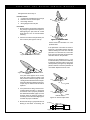
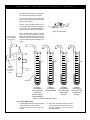
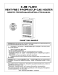
1
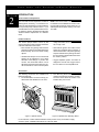
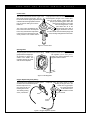
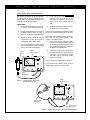
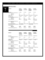
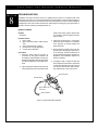
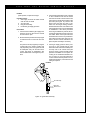
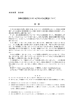
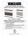
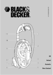
SERVICE MANUAL
VENT-FREE GAS HEATERS
VANGUARD FRONT
GRH/PV 005
CERAMIC PLAQUE MODELS
FOR YOUR SAFETY
WARNING: Improper installation, ad-
Do not store or use gasoline or other
flammable vapors and liquids in the
vicinity of this or any other appliance.
justment, alteration, service or maintenance can cause injury or property damage. Refer to this manual for correct
installation and operational procedures.
For assistance or additional information
consult a qualified installer, service
agency or the gas supplier.
M ERICA N
SS
N
A
O C IA T IO
CE RTIFIED
Save this manual for future reference.
Y STANDARD
ET
S
AF
N ATI ONAL
ITH
S
W
A
• Do not try to light any appliance.
• Do not touch any electrical switch; do
not use any phone in your building.
• Immediately call your gas supplier
from a neighbor’s phone. Follow the
gas supplier’s instructions.
• If you cannot reach your gas supplier,
call the fire department.
COMPL
IES
IGN
ES
D
FOR YOUR SAFETY
WHAT TO DO IF YOU SMELL GAS
G 009
V E N T - F R E E
TABLE
OF
G A S
H E A T E R
S E R V I C E
M A N U A L
Section 1 - Safety Information
Safety Requirements .............................................................................................. 3
Warnings ................................................................................................................. 3
CONTENTS
Section 2 - Introduction
Technical Service Department ............................................................................... 4
Product Features .................................................................................................... 4
Accessories ............................................................................................................ 4
Section 3 - General Operation and Component Descriptions
General Operation .................................................................................................. 5
Burner Assembly .................................................................................................... 5
Ignition System ....................................................................................................... 5
Control Valve .......................................................................................................... 6
Gas Regulator ........................................................................................................ 6
Oxygen Depletion System ...................................................................................... 6
Section 4 - Tools and Equipment ................................................................................. 7
Section 5 - Installation
Gas Type ................................................................................................................ 8
Location: Safety Precautions .................................................................................. 8
Gas Supply Installation ........................................................................................... 9
Propane Installation ................................................................................................ 10
External Regulators ................................................................................................ 10
Section 6 - Test Procedures
Testing Gas Supply Line Connections ................................................................... 11
Testing Heater Gas Connections ........................................................................... 11
Correcting Leaks .................................................................................................... 11
Testing Control Valve and Thermocouple .............................................................. 12
Section 7 - Specifications ............................................................................................. 13
Section 8 - Troubleshooting
Ignition Problems
No Spark ................................................................................................................. 14
Ignitor Sparks, But Pilot Will Not Light .................................................................... 15
Pilot Lights, But Will Not Stay Lit ............................................................................ 16,17
Main Burner Does Not Light (pilot stays lit) ........................................................... 18
Delayed Ignition Of Main Burner ............................................................................ 18
Combustion Problems
Backfiring During Operation ................................................................................... 19
Smoke or Unwanted Odors .................................................................................... 19
Gas Odor ................................................................................................................ 19
Service Information ...................................................................................................... Back Page
2
V E N T - F R E E
SECTION
1
G A S
H E A T E R
S E R V I C E
M A N U A L
SAFETY INFORMATION
Safety Requirements
This service manual is intended for use by
individuals with adequate electrical and mechanical skills. Attempts to repair this heater by
WARNINGS
!
WARNING ICON
individuals without those skills can result in
personal injury as well as property damage.
G 001
IMPORTANT: Read the Owner’s Manual carefully and completely before trying to assemble,
operate, or service this heater. Improper use of this heater can cause serious injury or death from
fire, explosion, electrical shock, electrocution, and carbon monoxide poisoning.
! DANGER
WARNING ICON
G 001
Carbon monoxide poisoning may lead to death!
Early signs of carbon monoxide poisoning resemble the flu, with headaches, dizziness, and/or
nausea. If you have these signs, the heater may not be working properly. Get fresh air at once!
Have heater serviced. Some people such as pregnant women, persons with heart or lung disease,
persons with anemia, those under the influence of alcohol, and those at high altitudes are more
affected by carbon monoxide than others. Make certain you read and understand all Warnings.
Keep the Owner’s Manual for reference. It is your guide to safe and proper operation of this heater.
1. Use only propane gas for models designated as propane.
2. Use only natural gas for models designated as natural.
3. If using propane model, do not place propane supply tank inside any structure. The
propane supply tank must be located outdoors.
4. If you smell gas
• Shut off gas supply.
• Do not try to light any appliance.
• Do not touch any electrical switch; do not use any phone in your building.
• Immediately call your gas supplier from a neighbor’s phone. Follow the gas supplier’s
instructions.
• If you cannot reach your gas supplier, call the fire department.
5. Never install the heater
• in sleeping quarters, a mobile home, or a recreational vehicle
• where curtains, furniture, clothing, or other flammable objects are less than 36 inches
from the front, top, or sides of the heater
• as a fireplace insert
• in high traffic areas
• in windy or drafty areas
6. Always run heater at LOW, THERMOSTAT/MEDIUM, or HIGH locked positions. Never set
control knob between locked positions. Poor combustion and higher levels of carbon monoxide
may result.
7. Open window to admit fresh, outside air when using heater. Open window one (1) or two (2)
inches. When used without fresh, outside air, heater may give off carbon monoxide gas.
8. Never run heater in small, closed room. Open door into next room to help ventilate.
9. If heater shuts off, do not relight until you provide fresh, outside air. If heater keeps shutting
off, have it serviced.
10. Do not run heater
• where flammable liquids or vapors are used or stored
• under dusty conditions
11. Never place any objects on the heater.
12. Surface of heater becomes very hot when running heater. Keep children and adults away
from hot surface. Heater will remain hot for a time after shutdown. Allow surface to cool
before touching.
13. Make sure grill guard is in place before running heater.
14. Do not alter heater or its controls. Any change may create a safety hazard.
15. Make sure heater is turned off, unplugged, and cool before servicing.
3
V E N T - F R E E
SECTION
2
G A S
H E A T E R
S E R V I C E
M A N U A L
INTRODUCTION
Technical Service Department
The Technical Service Department, located in
Bowling Green, Kentucky, is committed to assisting our Authorized Service Centers and Dealers to provide prompt, efficient service. If you
need assistance or have questions about servicing problems, please call DESA International’s
Technical Service Department at 1-800-3235190.
NOTE: This number is ONLY for technical service assistance and CANNOT be used for ordering parts, billing questions, order status, etc. For
sales department and parts ordering, call 1-502781-9600.
Product Features
The ceramic plaque heaters covered by this
service manual have many features that assure
customer satisfaction and comfort.
• Infra-red Heat: The glowing ceramic burner
plaques give off infra-red radiant light which
travels through the air and heats nearby
objects.
outage, the heater can be operated manually on high or low.
• Piezo Electric Ignition: The heater can be
started and operated without matches or
other external means. The pilot is ignited by
a spark created from the piezo ignitor when
the control knob is depressed and turned to
the “PILOT” position.
• Variable Heat Output: The non-thermostat
heaters can be adjusted to one of three
alternative heat settings to provide user
comfort. The thermostat heaters can be
adjusted to the desired heat setting to permit economical use. In the event of a power
• Oxygen Depletion System: The heater is
designed to shut off if the oxygen level in
the room falls to an unacceptable level.
Accessories
The following accessories are available from
DESA International:
1. Fan Kit GA2100A. The fan accessory provides better heat distribution in the room.
2.
Floor Mounting Stand GA4000 (3-plaque
models) and GA4010 (5-plaque models).
The floor stand allows the heater to be
installed away from a wall.
OPTIONAL FLOOR MOUNT-GRH
FAN ACCESSORY-GRH
Figure 1. Optional Fan Kit
Figure 2. Optional Floor Mounting Stand
For accessories, contact authorized dealers of this product. If they are unable to supply
accessory parts, call DESA International at 1-502-781-9600.
4
A 005
A 007
V E N T - F R E E
SECTION
3
G A S
H E A T E R
S E R V I C E
M A N U A L
GENERAL OPERATION AND COMPONENT DESCRIPTIONS
General Operation
NOTE: See Owner’s Manual for operating
procedure.
“PILOT” position so that the heater is ready to
use.
The heater is operated by the control knob
located on the top of the heater. Be sure that the
service supply valve is open and that the manual
shut-off valve (Figure 8, page 9) is fully open.
Depressing the control knob and turning it to the
“PILOT” position will direct gas to the pilot and
provide a spark to light the pilot. The control
knob must be held down (at least 10 seconds)
until the thermocouple is heated enough to hold
the valve open. Once the pilot flame is
established, the control knob can be released
and turned to any of the operating position
settings. The control knob can also be left in the
Turning the control knob operates the control
valve and directs the flow of gas to the pilot and
the burner plaques. The gas is mixed with air
and is injected into the burner chambers through
tubes in the bottom of the burner. The air/gas
mixture burns on the surface of the ceramic
burner plaques, causing the ceramic plaques to
glow with a radiant orange color. With proper
care and servicing, the heater should give many
years of satisfactory use to the customer. Be
sure to inspect and service the heater at least
annually.
Burner Assembly
The burner assembly is constructed of a plated
steel burner case with ceramic plaques cemented into the face. A metal frame assures
uniform spacing between the plaques. The gas
orifices are mounted at the bottom of the air/gas
inlet tubes. The air/gas mixture is distributed to
the plaques through the steel burner chambers
and through the small holes in the ceramic
plaques. The air/gas mixture burns near the
surface of the ceramic plaques, resulting in the
production of both radiant and convected heat.
Ignition System
The ignitor assembly utilizes a piezo electric
ignition system. The spark generator is built into the control valve and will provide a spark to the pilot when the control
knob is fully dePilot
pressed and turned
from the “OFF” position to the “PILOT” position.
The resulting high voltage spark ignites the gas
at the pilot tube. The pilot flame will
in turn light the main burners
when the control knob is
rotated to the desired
heat setting.
Control
Valve
IGNITION SYSTEM
GRH/P027
Figure 3. Ignition System
5
V E N T - F R E E
G A S
H E A T E R
S E R V I C E
M A N U A L
Control Valve
The control valve directs the flow of gas to the
pilot burner and the main burners. The control knob should be slightly depressed and
rotated to select the appropriate heat setting, the “PILOT” setting or to turn the
heater off.
The control valve will maintain gas
flow to the main burner and the pilot
burner only if the thermocouple which
is mounted on the pilot burner is sufficiently heated. The heated thermo-
couple provides a low level electric current to an
electromagnetic plunger in the control valve.
This low level electric current keeps the
plunger open allowing gas to flow to the
pilot and the main burner. If the pilot
flame is extinguished, or if the
pilot flame lifts off of the
thermocouple due to lack of
oxygen, the electric current to
the valve will be reduced and the plunger will
close, shutting off all gas flow to the heater.
Gas Valve
GRH/P028
Figure 4. Control Valve
Gas Regulator
The gas regulator is used to reduce the incoming
gas pressure to the appropriate pressure for proper operation of the heater. The
regulator pressure is preset
and cannot be adjusted.
NOTE: Propane heaters also require an external regulator (11"-14" W.C.) be installed. The external regulator is not
supplied with the heater.
Figure 5. Gas Regulator
Oxygen Depletion System (O.D.S.)
GAS REGULATOR
The pilot burner is designed to produce a precision flame which will lift off of the pilot
thermocouple if the oxygen content of the surrounding air is too low.
The resulting cooling
of the pilot thermoPilot
GRH/P 032
couple will cause the control valve to close,
shutting off all gas flow to the
heater. The oxygen depletion system is required
on all models of ventfree heaters covered
by this manual.
Control
Valve
O.D.S.
GRH/P 029
Figure 6. Oxygen Depletion System
6
V E N T - F R E E
SECTION
4
G A S
H E A T E R
S E R V I C E
M A N U A L
TOOLS AND EQUIPMENT
Tools You May Need
Phillips Screwdriver
Slotted Screwdriver
1/4 inch (Socket) Nutdriver
5/16 inch (Socket) Nutdriver
5/16 inch Open End Wrench
5/8 inch Open End Wrench
7/8 inch Open End Wrench
9 mm Open End Wrench
10 mm Open End Wrench
11 mm Open End Wrench
13 mm Open End Wrench
15/64 inch Ignition Wrench (Orifices)
1/16 inch Punch
Needle Nose Pliers
Equipment
The following items are recommended for
servicing, troubleshooting, or installing ventfree gas heaters:
Item
Source Information
1. Water Manometer
(For Inlet and Manifold Pressure Testing)
Controls, Inc.
P.O. Box 52275
Raleigh, North Carolina
1-800-334-5886
Item: ESL-16
Approximate Cost: $14.00
2. BASO Millivolt Test Kit.
(For Testing Valves
and Thermocouples)
DESA International
P.O. Box 90004
Bowling Green, KY 42102-9004
502-781-9600
Item: GA5000
3. Low Pressure Test Set
(For Leak Testing Gas
Supply Line To Heater)
Controls, Inc.
P.O. Box 52275
Raleigh, North Carolina
1-800-334-5886
Item: 78060
Approximate Cost: $40.00
4. Manual Shutoff Valve With
1/8" NPT Tap. (For
Installing Heater To Gas
Supply)
DESA International
P.O. Box 90004
Bowling Green, KY 42102-9004
502-781-9600
Item: GA5010
7
V E N T - F R E E
SECTION
5
G A S
H E A T E R
S E R V I C E
M A N U A L
INSTALLATION
Before servicing the heater, be sure that the
installation conforms to local codes and all safety
precautions outlined in the Owner’s Operation
and Installation Manual. In the absence of local
codes, the installation must conform with the
National Fuel Gas Code, ANSI Z223.1 1984,
and ADDENDA Z223.1a-1987 also known as
NFPA 54*. Only qualified (licensed or trained)
persons should install the product.
For detailed installation instructions, see the
Owner’s Operation and Installation Manual that
is packaged with the heater.
* Available from the American National Standards
Institute, Inc., 1430 Broadway, New York, NY
10018 or from the National Fire Protection
Association Inc., Batterymarch Park, Quincy,
MA 02269.
Gas Type
Be sure that the type of gas supplied to the
heater is the same as that indicated on the
heater data plate. If you observe that the gas
supply is different than that specified on the
heater data plate, DO NOT operate the heater
until the correct gas supply is installed. Verify
that the regulator, burner orifices, and pilot as-
sembly are for the same gas type as is indicated
on the heater data plate (see “SPECIFICATIONS”, page 13). DO NOT attempt to convert
a heater from one gas type to another (i.e.,
Propane to Natural Gas or vice versa). If necessary, replace the heater with a model suitable for
the type of gas being supplied.
Wall or Base Mounting
See Owner’s Manual for detailed instructions for
wall or base mounting.
Location: Safety Precautions
Be sure that the following safety precautions
have been followed for locating the heater:
1. DO NOT install the heater in sleeping quarters, mobile homes or recreational vehicles.
2.
DO NOT install heater as a fireplace insert.
3.
The heater should be located to give easy
access for operation, servicing and inspection.
4.
DO NOT install in areas where curtains,
drapes, clothing or other flammable materials are within 36 inches of the front, top and
sides of the heater.
5.
This heater has been designed for wall
mounting. The clearances from the heater
to combustible surfaces MUST NOT be
less than shown in Figure 7. These are
absolute minimum clearances. Greater
clearances should be allowed if possible.
The heater can also be mounted to an
optional floor mounting base that is sold as
a separate accessory. If a base accessory
is used, be sure the base is securely attached to the floor.
If the heater is installed in a residential garage,
the following precautions should be taken:
1. The heater pilot and burners must be at
least 18 inches above the floor.
2. The heater must be located or reasonably
protected, so as not to be subjected to
damage by a moving vehicle.
CEILING
36"
Minimum
6"
Minimum
From
Sides Of
Heater
Left
Side
Right
Side
FLOOR
LEARANCE
3" Minimum To Top Surface
Of Carpeting, Tile Or Other
Combustible Material
GRH/PV 011
Figure 7. Mounting Clearances As Viewed
From Front of Heater
8
V E N T - F R E E
G A S
H E A T E R
S E R V I C E
M A N U A L
Gas Supply Installation
1.
Use only new, black iron or steel pipe.
Copper tubing may be acceptable in some
areas but should be internally tinned or
equivalently treated to resist corrosion by
sulphur compounds. CHECK LOCAL
CODES.
4.
The supply system must include a manual
shut-off valve, a union in the line and a
plugged 1/8 inch NPT tap. The tap should
be accessible for test gauge connections
upstream of the gas supply connection to
the heater.
2.
The gas supply line shall be sized and
installed to provide a sufficient supply of
gas to meet the maximum demand of the
heater without undue loss of pressure.
5.
Include a drip leg (trap) in the supply line.
The purpose of the drip leg is to prevent
moisture and contaminants in the gas supply from entering the heater controls. The
drip leg should be within reach to permit
cleaning or emptying. A drip leg should not
be located where condensation is likely to
freeze. Failure to use a drip leg can result in
operational difficulties with the heater.
Model Installed
3-Plaque Models
5-Plaque Models
3.
Supply Line
3/8 inch or greater
1/2 inch or greater
The sealant used on the threaded joints of
the gas pipe must be the specific type
resistant to the action of liquid petroleum
(LP) gas. Apply sealant lightly to the male
threads to ensure excess sealant does not
enter the lines. Any excess sealant could be
forced into the pipe and result in clogged
valves.
The gas supply to the heater must be regulated
to maintain the inlet pressure within the following limits:
Models
Natural Gas
Propane
Gas Pressure
(Inches W.C.)
7" Min. / 10.5" Max.
11" Min. / 14" Max.
IMPORTANT: Pressure regulator
must be held with wrench when
connecting gas piping and/or fittings
to pressure regulator.
1/8" NPT Plug Tap
External Regulator
(For LP Heaters Only)
Union
Manual Shut-off
Valve
GAS CONNECTION
GRH/P 001A
Drip Leg
(Trap)
Figure 8. Gas Connection
9
V E N T - F R E E
G A S
H E A T E R
S E R V I C E
M A N U A L
Propane Installations
!
CAUTION: Propane models require an
external regulator (not supplied with heater).
The external regulator must be connected between the heater and the propane supply tank.
This regulator must reduce the incoming supply
pressure to a maximum of 14" W.C. Under no
circumstances should this heater ever be connected directly to a propane supply tank.
WARNING ICON
G 001
A typical propane installation is shown (below
right) in Figure 9. For details concerning tank or
cylinder location and installation, refer to NFPA
Pamphlet No. 58 and the laws in your locality.
Supply
Tank
3 FT
MIN
3 FT
MIN
3 FT
MIN
Manual Shutoff Valve
With 1/8" NPT Tap
CYLINDER LOCATION
GRH/PV 016
Regulator
REGULATOR INSTALLATION
GRH/PV 018
Figure 9. Typical Propane Installation
External Regulators - Vents
External regulators should be installed with the
vent pointing down as shown in Figure 9. Some
regulators have a so-called “drip lip” surrounding the vents which acts as a shield for the
recessed vent opening. This lip makes it more
difficult for freezing rain or sleet to plug a vent
that has been installed pointing down. Older
style vents may not have the lip and are far less
resistant to freeze-up problems (see Figure 10).
A regulator with the drip lip design installed
outdoors does not require additional protection
if the vent is pointing down, unless subjected to
upward splatter from rain.
Drip
DRIPLip
LIP
Older regulators with the non-drip lip vent construction require additional protection, such as a
hood, cover, encasement, etc. The external
regulator should be installed high enough above
ground level (at least 18 inches) so that rain
splatter does not block or freeze the vent. Extra
protection for the vent may be needed in areas
where there is heavy snow fall.
Be sure the external regulator is installed in
accordance with NFPA No. 58 and any other
applicable local regulations, as well as the
manufacturer’s instructions.
GRH/P
026 Lip
No
Drip
Figure 10. Regulator Vent Drip Lips
10
V E N T - F R E E
SECTION
6
G A S
H E A T E R
S E R V I C E
M A N U A L
TEST PROCEDURES
Testing Gas Supply Line Connections
!
WARNING: All gas piping and connections must be tested for leaks after installation or
servicing. All leaks must be corrected immediately.
WARNING ICON
!
G 001
WARNING: NEVER USE AN OPEN
FLAME TO CHECK FOR A LEAK. Apply a
solution of liquid detergent and water to all
connections. The formation of bubbles indicate
leaks that must be corrected.
WARNING ICON
2.
Connect a low pressure gauge to the 1/8
inch NPT pressure tap (see “Equipment”,
page 7). The manual shut-off valve should
be closed.
3.
Open the gas supply service valve to pressurize the system. Close the service valve
tightly.
4.
The low pressure gauge should read at
least 11 inches W.C. Bleed off pressure by
slowly opening the manual shut-off valve
to vent enough gas to reduce the pressure
to exactly 10 inches W.C.
5.
If the pressure remains at 10 inches W.C.
for 10 minutes, you can assume the gas
supply system is leak tight. If the pressure
drops, apply a solution of liquid detergent
and water to all connections and observe
carefully for forming and expanding bubbles.
Bubbles forming indicate a leak that must
be corrected.
G 001
Pressure Testing Supply Line
1. The heater and its control valve must be
disconnected from the gas supply piping
system during any testing of the gas supply
piping system when test pressures are in
excess of 14" W.C. (1/2 PSIG).
2.
Testing Gas Supply Piping System
1. Inspect all connections from the gas supply
to the manual shut-off valve to be sure they
are tight or closed.
The heater must be isolated from the gas
supply piping system by closing its individual manual shut-off valve during any pressure testing of the gas supply piping system
when pressures are equal to or less than
14" W.C. (1/2 PSIG).
Testing Heater Gas Connections
1.
Remove the front panel of the heater by
removing the two screws near the bottom
corners and pulling the bottom of the panel
forward and then downward. Turn heater
control knob to the “OFF” position. Open
the manual shut-off valve (see Figure 8,
page 9). Apply solution of liquid detergent
and water to all connections from the supply
line to control valve. Bubbles forming indicate leaks that must be corrected.
2.
Light the heater and check all remaining
internal connections for leaks with the liquid
detergent and water solution.
Correcting Leaks
1.
2.
To correct a leak on flared tubing, first try
tightening the connection. If this doesn’t
work, reflare or replace the section of tubing.
On threaded piping, try tightening or redoping first. If the leak continues, take the
connection apart and inspect the threads. If
necessary, cut new threads or replace the
section of piping.
3.
If steps 1 and 2 fail to correct the problem,
look for pinholes in the pipe or fittings and
check for splits in the tubing. Replace materials or fittings that are defective.
11
V E N T - F R E E
G A S
H E A T E R
S E R V I C E
M A N U A L
Testing Control Valve and Thermocouple
The following procedure can be used to determine if the valve and thermocouple meet specification. This procedure requires a BASO millivolt tester. See Equipment, page 7.
PROCEDURE
1. Connect the valve attachment to the control valve in place of the thermocouple.
2.
Plug the valve attachment connector into
the BASO millivolt tester as shown in
Figure 11. Set BASO to 0-500 Milliamps.
3.
Adjust the current to 80 ma (if using dry
cell batteries, set the current level by
adjusting the rotary volume knob).
4.
Turn control knob from the OFF position
to the PILOT position. Check to see if the
control valve holds in satisfactory.
500
300
0
20
MILLIAMPS
0-500
700
30
10
40
90
DC MILLIVOLT
6.
Gradually reduce ma level until the control valve drops out. Note result.
Hold-in current specification: 230 ma maximum
Drop-out current specification: 80 ma minimum
If the control valve operates correctly during the
above test, it is likely that the problem is the
result of a bad thermocouple.
7. Connect the thermocouple attachment
to the thermocouple as shown in Figure
12. Be sure the red clip is attached to the
outer (copper) thermocouple sheathing.
Set BASO to 0-500 Millivolts.
Light the burner pilot and continue to hold
the control knob down to keep the control
valve open, or remove the thermocouple
and hold it over an open flame (a BIC
lighter can be used).
0
50
0
10
If the control valve does not hold in,
increase current levels by 10 ma and
repeat step 4. Repeat by 10 ma increments until the valve holds in. Note result.
8.
BASO
Milivolt Tester
Control
Valve
5.
Thermocouple output specification: 20-28 mv
0-1000
0-50
MILLIVOLTS
ADJUST
MILLIVOLTS
MILLIAMPS
If the thermocouple millivolt output is below
specification, replace the thermocouple.
Valve
Attachment
GRH/OV 032
BASO
Milivolt Tester
Figure 11. Testing Control Valve With
BASO Milivolt Tester
500
300
0
20
MILLIAMPS
0-500
700
30
40
10
90
0
50
0
10
DC MILLIVOLTS
0-1000
0-50
MILLIVOLTS
ADJUST
MILLIVOLTS
Thermocouple
Attachment
MILLIAMPS
GRH/OV 031
Thermocouple
Attachment
Figure 12. Testing Thermocouple With BASO Milivolt Tester
12
V E N T - F R E E
SECTION
7
G A S
H E A T E R
S E R V I C E
M A N U A L
SPECIFICATIONS
MODELS
VP1600
VP1600A
VP1600B
VP1600T
VP1600TA
VP2600
VP2600A
VP2600B
VP2600T
VP2600TA
Gas Type
Inlet Gas Pressure (Inches W.C.)
Maximum
Minimum
Supply Line
Inlet Fitting Size
Regulator Pressure (Inches W.C.)
Maximum
Minimum
Control Valve Type
LP Only
LP Only
LP Only
LP Only
14"
11"
3/8" or greater
1/2" NPT
14"
11"
3/8" or greater
1/2" NPT
14"
11"
1/2" or greater
1/2" NPT
14"
11"
1/2" or greater
1/2" NPT
8.2"
7.8"
Manual
8.2"
7.8"
Manual with
Thermostat
8.2"
7.8"
Manual
8.2"
7.8"
Manual with
Thermostat
Manifold Pressure (Inches W.C.)
Maximum
Minimum
Burner Orifice Diameter
Burner Orifice Diameter (B Model)
BTU/HR Output
Maximum
Minimum
Fresh Air Opening (Minimum)
7.9"
7.9"
7.5"
7.5"
.028" (#70 drill) .028" (#70 drill)
.042" (#58 drill)
7.9"
7.2"
7.5"
6.8"
.028" (#70 drill) .028 "(#70 drill)
.042" (#58 drill)
16,000
6,000
16 sq. in.
16,000
6,000
16 sq. in.
26,000
6,000
26 sq. in.
26,000
11,000
26 sq. in.
MODELS
VN1800
VN1800A
VN1800B
VN1800T
VN1800TA
VN3000
VN3000A
VN3000B
VN3000T
VN3000TA
Gas Type
Inlet Gas Pressure (Inches W.C.)
Maximum
Minimum
Supply Line
Inlet Fitting Size
Regulator Pressure (Inches W.C.)
Maximum
Minimum
Control Valve Type
Natural Only
Natural Only
Natural Only
Natural Only
10.5"
7"
3/8" or greater
1/2" NPT
10.5"
7"
3/8" or greater
1/2" NPT
10.5"
7"
1/2" or greater
1/2" NPT
10.5"
7"
1/2" or greater
1/2" NPT
6.2"
5.8"
Manual
6.2"
5.8"
Manual with
Thermostat
6.2"
5.8"
Manual
6.2"
5.8"
Manual with
Thermostat
Manifold Pressure (Inches W.C.)
Maximum
Minimum
Burner Orifice Diameter
Burner Orifice Diameter (B Model)
BTU/HR Output
Maximum
Minimum
Fresh Air Opening (Minimum)
5.5"
5.5"
5.1"
5.1"
.041" (#59 drill) .043" (#57 drill)
.042" (#58 drill)
5.2"
5.2"
4.8"
4.8"
.043" (#57 drill) .043 "(#57 drill)
.042" (#58 drill)
18,000
6,600
18 sq. in.
30,000
6,600
30 sq. in.
18,000
6,600
18 sq. in.
30,000
12,000
30 sq. in.
13
V E N T - F R E E
SECTION
8
G A S
H E A T E R
S E R V I C E
M A N U A L
TROUBLESHOOTING
Installation and repair should be done by a qualified service person in accordance with local
ordinances and codes. The room heater should be inspected before use and at least annually by
a professional service person. It is important that control compartments, burners and circulating air
passageways of the room heater be kept clean. More frequent cleaning may be required due to
excessive lint from carpeting, bedding material, etc.
Ignition Problems
Problem
No Spark
that it is free of dust, grease, carbon buildup or moisture. Clean the ignitor with a dry
rag and retest.
Possible Causes
1. Ignitor cable
2. Ignitor electrode position and/or cleanliness
3. Ignitor electrode body cracked
4. Control knob not fully depressed
5. Control valve malfunction
Procedures
1. Check the ignitor cable at the point of
connection to the ignitor electrode. Be
sure that the cable insulation is not split or
damaged and that the cable is fully pressed
onto the serrated point of the ignitor electrode.
2. Inspect the ignitor electrode to be sure that
it is properly positioned in the bracket and
3. Inspect the porcelain body of the ignitor
electrode to be sure that it is not cracked.
If the porcelain is cracked, replace the
ignitor electrode.
4. Be sure that the control knob is fully depressed when attempting to ignite the pilot. If necessary, instruct the customer on
proper operating procedure (see Owner’s
Operation and Installation Manual for
heater in question).
5. If sparking is still not observed after the
above steps have been taken, replace the
control valve assembly. Be sure to turn off
the manual shut-off valve before beginning replacement of the control valve.
Ignitor Electrode
Porcelain Body
Ignitor cable point of
connection
Cable Insulation
Ignitor/Pilot
GRH/P 030
Figure 13. Ignitor Electrode Assembly
14
V E N T - F R E E
G A S
H E A T E R
Problem
Ignitor sparks, but pilot will not light
Possible Causes
1. Gas supply is turned off and/or manual
shut-off valve is closed
2. Air in pilot line
3. Dirty pilot assembly
4. Insufficient gas supply pressure
Procedures
1. Check to be sure that the gas supply to the
heater is turned on. Be sure the manual
shut-off valve is open.
2. Be sure that the pilot line has been purged
for sufficient time to remove air from the
line.
The pilot line can be purged by turning the
control knob to the “PILOT” position and
fully depressing the knob. Ignition should
be attempted every 30 seconds until a
correct pilot flame is established. See
Owner’s Manual for correct ignition procedure.
S E R V I C E
M A N U A L
3. Check the pilot assembly for dirt, cobwebs
or other restrictions. Be sure the heater
has been turned off. First remove the wire
clip from the bi-metal strip located on the
pilot tube (see Figure 14). Remove the
brass cover and clean any dust or cobwebs from the air/gas mixing chamber.
Reassemble the brass cover with the wire
clip and retest to see if a correct pilot flame
is established. If the above procedure
does not give satisfactory results, disconnect the pilot assembly and remove it from
the heater. Blow out the pilot tube from
both directions to remove any restrictions.
Also inspect the pilot line tubing for dirt,
kinks in the line or other restrictions. Replace the pilot assembly if necessary.
4. Check gas supply pressure at the pressure tap on the manual shut-off valve
below the heater and at the manifold pressure tap next to the control valve (see
Figure 21, page 17) to be sure that enough
pressure is available to the system according to the “SPECIFICATIONS” section on page 13. If the inlet pressure is
correct and the manifold pressure is low,
replace the regulator, control valve or inlet
tubing as required.
Problem
Bi-metal Strip
Wire Clip
Brass Cover
PILOT
GRH/P 007A
Figure 14. Ignitor/Pilot Assembly
15
V E N T - F R E E
G A S
H E A T E R
S E R V I C E
M A N U A L
Pilot ignites but will not stay lit
Possible Causes
1. Control knob not held down long enough
2. Defective valve or thermocouple
3. Not enough fresh air
4. Wrong air/gas mixture at pilot
BAD PILOT/LP
GRH/OV 008
LP
Procedures
1. Be sure that the control knob is held down
long enough to get the thermocouple hot.
After lighting the pilot, hold the control
knob down for 10 to 15 seconds before
releasing.
2. Check to be sure that the pilot flame pattern is correct (see Figures 15 & 16).
Figure
15. Correct LP Pilot FlameGRH/OV 007
GOOD PILOT/LP
BAD PILOT
GRH/OV 010
Natural Gas
18. Pilot Barrel Liftoff
Figure 17.
LP
heater should be relocated to a more
protected area.
If the pilot flame is incorrect as shown in
Figure 18, it is possible that the cold-start
choke is allowing too much air to enter the
pilot tube. Turn the heater off, remove the
front cover from the heater, and inspect the
cold-start choke on the pilot tube.
Insert a 1/4 inch diameter rod (i.e., a 1/4
inch drill bit will do) under the bi-metal strip
to adjust the cold-start choke to the nearly
closed position (see Figure 19). Relight the
pilot and observe to see if the pilot flame is
more stable. Replace the front cover.
Figure 16. Correct Natural Gas Pilot Flame
GOOD PILOT
GRH/OV 009
If the pilot flame appears to be normal,
check the control valve according to the
test procedure outlined on page 12 under
“Testing Control Valve and Thermocouple”.
If the valve passes the testing, the thermocouple may be defective and should be
replaced.
3. If the pilot flame is lifting off the thermocouple as shown in Figure 17, check to be
sure that the room is properly ventilated.
See “SPECIFICATIONS”, page 13, for the
minimum fresh air openings required. If
necessary, instruct the user to slightly open
a window for proper ventilation.
4. Be sure that strong or gusty drafts are not
blowing on the heater. If necessary, the
FLAME LIFTING/LP
GRH/OV 007A
LP
FLAME LIFTING
Liftoff
GRH/OV 009A
Liftoff
Natural Gas
Figure 18. Thermocouple Liftoff
1/4" Rod
Figure 19. Cold-Start Choke Adjustment
GRH/OV 027
COLD-START CHOKE ADJUSTMENT
16
V E N T - F R E E
G A S
H E A T E R
S E R V I C E
M A N U A L
If the pilot flame is short as shown in Figure
20, check for low pressure to the pilot.
First, be sure that the gas supply inlet
pressure to the heater is adequate. Check
the line for proper size.
Second, check manifold pressure with a
manometer to be sure that the regulator is
not defective. See “SPECIFICATIONS” on
page 13 for the model you are servicing.
SHORT FLAME/LP
GRH/OV 012A
Figure 20. Short Flame
Connect Rubber
Hose At Manifold
Pressure Tap
Third, check the pilot assembly and pilot
line to be sure that a restriction, such as
dust or dirt is not present. Blow out the pilot
assembly from both directions to remove
any dirt. Replace the pilot assembly if necessary.
6
6
6
6
5
5
5
5
4
4
4
3
7.7"
2
Manifold
Pressure
Tap (1/8" NPT)
Control
Valve
1
Control
Valve
Manometer
3
7.0"
2
1
3
4
5.3"
3
2
2
5.0"
1
1
0
0
0
0
1
1
1
1
2
2
2
2
3
3
3
3
4
4
4
4
5
5
5
5
6
6
6
6
3-Plaque
Thermostat &
Non-Thermostat
& 5-Plaque
Non-Thermostat
Propane Models
5-Plaque
Thermostat
Propane Models
3-Plaque
Thermostat &
Non-Thermostat
Natural Gas
Models
5-Plaque
Thermostat &
Non-Thermostat
Natural Gas
Models
Figure 21. Measuring Manifold Pressure
How To MANIFOLD
Use A Manometer
PRESSURE-GRH
1. Fill tube with water until you see the water
level off at zero (0) on both sides.
2. Connect rubber hose to the line to be
tested.
GRH/OV 026
3. Read the manometer water level both
above and below the zero (0) mark, then
add the readings to give the correct
manifold pressure.
17
V E N T - F R E E
G A S
H E A T E R
Problem
Main burner does not light (pilot stays lit)
Propane (LP) Models Only:
A. Be sure tank is not empty or nearly
empty.
B. Be sure tank is not frozen due to high
usage rates on a small propane cylinder. If many appliances or heating
devices are being run off the same
tank, evaporation rates can cause the
remaining liquid to cool and create
M A N U A L
frost or ice on the outside of the tank.
The ice acts as an insulator and can
reduce the evaporation rate and the
pressure to your heater. If an improper tank size is causing a low
supply pressure to the heater, contact the local LP gas supplier for proper
tank sizing.
Possible Causes
1. Low inlet gas pressure
2. Burner orifice is clogged
3. Burner orifice is not correct
Procedures
1. Be sure that the supply pressure and line
size to the heater is adequate. Refer to
“SPECIFICATIONS” on page 13 for the
model you are servicing. If the supply line
is the correct size and the supply pressure is low, contact your local gas company or LP supplier.
S E R V I C E
2.
Check the burner orifices to be sure that
they are not clogged. Remove the
orifice(s) and examine for dirt or particles
which would restrict the flow of gas. DO
NOT attempt to clean the orifice(s) with a
wire. Blow out the orifice(s) or gently
clean. Replace the orifice(s) if necessary.
3.
Check the burner orifice size. Refer to
the proper drill size in “SPECIFICATIONS” on page 13 for the model you are
servicing. If an orifice is not the correct
size, it should be replaced.
Burner Orifice (Injector)
Washer
Injector Holder
Burner Orifice
GRH/P 031
Figure 22. Burner Orifice
Problem
Delayed ignition of main burner
Possible Cause
1. Low pressure to one or more burner
plaques.
18
Procedure
1. Check for the cause of low pressure by
following procedure number 3 under
“Problem: Gas odor” at the bottom of
page 19.
V E N T - F R E E
G A S
H E A T E R
S E R V I C E
M A N U A L
Combustion Problems
Problem
Backfiring during operation
Possible Causes
1. Burner damaged
2. Low pressure to one or more burner
plaques
Procedure
1. Inspect the ceramic burner plaques to
see if the plaques are cracked or badly
chipped. If a burner plaque is cracked or
broken, replace the burner.
2
Problem
Smoke or unwanted odors
Possible Causes
1. Oil or residue from manufacturing processes
2. Household chemicals
few hours of operation. If odors persist,
remove the front panel and examine the
inside of the heater cabinet for oil or
foreign material.
2.
Procedures
1. If oils or residues from manufacturing
processes are present in the heater, the
problem will usually be eliminated after a
Problem
Gas odor
3.
!
G 001
WARNING: If you smell gas:
• Shut off gas supply.
• Do not try to light any appliance.
• Do not touch any electrical switch; do
not use any phone in your building.
• Immediately call your gas supplier from
a neighbor’s phone. Follow the gas
supplier’s instructions.
• If you cannot reach your gas supplier,
call the fire department.
Procedures
1. Check all heater and gas supply connections for leaks. See procedures under
“Testing Gas Supply Line Connections”
and “Testing Heater Gas Connections”
on page 11 of this service manual.
2.
If all gas connections inside and outside
of the heater have been checked and
found to be free of leaks, check for a
defective control valve. Visually examine
the surface of the control valve to be sure
that it is not cracked, dented or damaged.
A small mirror and flashlight may be necessary to examine the rear of the valve.
Check to be sure that the valve is mounted
securely in a vertical position, and that
Some household chemicals, such as
paint, hair spray or glues can produce
unwanted odors when the heater is operating. Ventilate the room and advise the
user to discontinue using such products
while the heater is operating.
the control knob can be turned to all
positions. If any defect is found, replace
the control valve. Be sure to test all gas
connections for leaks after replacing the
control valve.
Possible Causes
1. Gas leak
2. Defective control valve
3. Dirt or particles clogging gas line
WARNING ICON
Check for low pressure to the burner by
following procedure number 3 under
“Problem: Gas odor” (bottom of page).
Low pressure to one or more burner
plaques can result in improper combustion and gas odor. Check burner operation at the “HIGH” setting to see if all
plaques have the same uniform color.
A. If one plaque is glowing less than the
others, dirt or particles may be clogging the line between the valve and
the burner, or the burner pipe may be
blocked by spider webs or other obstructions. Turn off gas to the heater
at the manual shut-off valve below
the heater. Remove the appropriate
gas line(s) to the burner and clean
foreign matter from the tubing. Check
the burner orifices and clean if necessary.
B. If all plaques do not develop a full
radiance, check manifold pressure at
the 1/8" NPT tap located next to the
control valve. See “SPECIFICATIONS” on page 13 for the model of
heater you are servicing. If manifold
pressure is low, check inlet (supply)
pressure to the heater. If the inlet
supply pressure is correct, clean the
inlet tube between the regulator and
valve. Replace the regulator and valve
if necessary.
19
TECHNICAL SERVICE
You may have further questions about installation, operation, or troubleshooting.
If so, contact DESA International’s Technical Service Department at 1-800-323-5190.
REPLACEMENT PARTS
Note: Use only original replacement parts. This will protect your warranty coverage for parts
replaced under warranty.
Parts Under Warranty
Contact authorized dealers of this product. If they can’t supply original replacement part(s), call
DESA International’s Technical Service Department at 1-800-323-5190.
When calling DESA International, have ready
• your name
• your address
• your heater’s model number
• how heater was malfunctioning
• type of gas used (propane or natural gas)
• purchase date
In most cases, we will ask you to return the defective part to the factory.
Parts Not Under Warranty
Contact authorized dealers of this product. If they can’t supply original replacement part(s), call
DESA International’s Parts Department at (502) 781-9600.
When calling DESA International, have ready
• your heater’s model number
• the replacement part number
ILLUSTRATED PARTS LISTS
Illustrated parts lists can be obtained free of charge. Send a self-addressed, stamped envelope
to the address listed below. List the heater model number and the date located in the lower right
corner of this page.
DESA
R
INTERNATIONAL
Corporate Headquarters
P.O. Box 90004
2701 Industrial Drive
Bowling Green, Kentucky 42102-9004
502-781-9600
098734-01
Rev. D
12/89