1
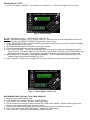
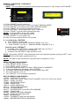
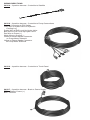
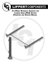
LIPPERTCOMPONENTS, INC. LCI LEVEL-UP WITH AUTOMATIC LEVELING OPERATION AND SERVICE MANUAL WARNING! FAILURE TO ACT IN ACCORDANCE WITH THE FOLLOWING MAY RESULT IN SERIOUS PERSONAL INJURY OR DEATH. THE USE OF THE LCI LEVEL-UP WITH AUTOMATIC LEVELING SYSTEM TO SUPPORT THE UNIT FOR ANY REASON OTHER THAN WHICH IT IS INTENDED IS PROHIBITED BY LIPPERT’S LIMITED WARRANTY. THE LIPPERT LEVELING SYSTEM IS DESIGNED AS A “LEVELING” SYSTEM ONLY AND SHOULD NOT BE USED TO PROVIDE SERVICE FOR ANY REASON UNDER THE COACH SUCH AS CHANGING TIRES OR SERVICING THE LEVELING SYSTEM. LIPPERT COMPONENTS, INC. RECOMMENDS THAT A TRAINED PROFESSIONAL BE EMPLOYED TO CHANGE THE TIRE ON THE UNIT. ANY ATTEMPTS TO CHANGE TIRES OR PERFORM OTHER SERVICE WHILE UNIT IS SUPPORTED BY THE LCI LEVEL-UP WITH AUTOMATIC LEVELING SYSTEM COULD RESULT IN DAMAGE TO THE 5TH WHEEL AND/OR CAUSE SERIOUS INJURY OR DEATH. WARNINGS! > BE SURE TO PARK THE UNIT ON SOLID, LEVEL GROUND. > CLEAR ALL JACK LANDING LOCATIONS OF DEBRIS AND OBSTRUCTIONS. LOCATIONS SHOULD ALSO BE FREE OF DEPRESSIONS. > WHEN PARKING THE UNIT ON EXTREMELY SOFT SURFACES, UTILIZE LOAD DISTRIBUTION PADS UNDER EACH JACK. > PEOPLE AND PETS SHOULD BE CLEAR OF UNIT WHILE OPERATING LEVELING SYSTEM. > BE SURE TO KEEP HANDS AND OTHER BODY PARTS CLEAR OF FLUID LEAKS. OIL LEAKS IN THE LIPPERT LEVELING SYSTEM MAY BE UNDER HIGH PRESSURE AND CAN CAUSE SERIOUS SKIN PENETRATING INJURIES. BASIC JACK OPERATION 1. Front jacks or Landing gear jacks. 2. Level-Up jacks. Landing gear jacks can be operated any time the system is “ON” but NOT in the “AUTO MODE.” By pushing the “FRONT” button, both front or landing gear jacks can be extended. If the touch panel is put in the “RETRACT” mode, indicated by the orange illuminated LED next to the “RETRACT” button, the front jacks can be retracted together by pushing the “FRONT” button. The Level-Up jacks operate when the “AUTO MODE” is activated or the touch panel is in the “MANUAL MODE.” Once system is in “MANUAL MODE,” pressing the “REAR” button will extend all Level-Up jacks at the same time. Press the “LEFT” or “RIGHT” buttons to operate Level-Up jacks to move on the left or right side of the coach, respectively. PRIOR TO OPERATION The leveling system shall only be operated under the following conditions: 1. The unit is parked on a reasonably level surface. 2. Be sure all persons, pets and property are clear of the coach while LCI Level-Up Automatic System is in operation. DROPPING OFF UNIT 1. Push touch panel “ON/OFF,” Fig. 2(A) to turn system on. LCD Screen lights up, Fig. 2(B). A B C Fig. 2 - Touch Panel 2. LCD will display status … “NOT READY JACKS: UP” NOTE: Orange arrow lights, Fig. 2(C) may come on, indication the current disposition of the unit, in this case the FRONT and RIGHT sides of the unit are low. 3. Push “FRONT BUTTON” to extend landing gear jacks and lift front of vehicle to take the weight of the 5th wheel off of the hitch. 8QFRXSOHWKH¿IWKZKHHOFRQQHFWLRQRQWKHWRZYHKLFOH 5. Pull tow vehicle away and park at a safe distance. 6. Push “AUTO LEVEL.” The unit will commence to auto level by setting the landing gear jacks close to level. The driver side rear jack will then extend and touch the ground, followed by the passenger side rear jack. There may be several level checks from the system at this time. 7. When auto level is complete, LCD indicates READY - Jacks: Down and the green light in the middle of the jack buttons will light Fig. 3(D). 8. Push “ON/OFF” button to turn system off or system will time out and shut off automatically. D Fig. 3 Touch Panel - Unit Level RECONNECTING THE UNIT TO A TOW VEHICLE 1. Be sure main power switch “ON.” 2. LCD display will indicate “READY: JACKS DOWN.” 3. Push “LEFT” and “RIGHT” buttons at the same time. 4. Unit will raise up to the point where the AUTO LEVEL was started, (normal starting point from where it was disconnected from the tow vehicle. 5. Connect tow vehicle and make sure 5th wheel and pin are connected and locked. 6. Push “UP” arrow until” AUTO RETRACT” appears in LCD screen. 7. Push “ENTER.” System will immediately retract all jacks. MANUAL OPERATION, HYDRAULIC 1. Front jacks NOTE: The front jacks will operate manually any time system is “ON” except “AUTO MODE.” Fig. 5 Fig. 4 1) Push “ON/OFF” to turn system on. 2) Push “UP” ARROW once or until screen reads “MANUAL MODE.” 3) Push “ENTER” once while screen reads “MANUAL MODE.” 4) Push “FRONT” to extend front landing gear legs. 5) Push “RETRACT” and orange LED, Fig. 6, comes on. 6) Push “FRONT” to retract front landing gear legs: NOTE: If orange LED is on legs will retract If orange LED is off legs will extend 7) Push “ON/OFF” to turn system off. 8) After 3 minutes system will turn off by itself. Fig. 6 2. Level-Up jacks - EXTEND a. Turn “ON/OFF” button “ON.” b. Push scroll arrow to display “MANUAL MODE,” see Fig. 4 c. Push “ENTER,” see Fig. 4. “MANUAL MODE” displayed, Fig. 5 Level-Up jacks - RETRACT e. To retract , push “RETRACT” (orange LED lights up), see Fig. 6 f. Push “REAR” to retract all Level-Up jacks. g. To extend, the “RETRACT“ light should be “OFF.” NOTE: By pushing “RIGHT,” both passenger side Level-Up jacks operate;; pushing “LEFT,” both driver’s side Level-Up jacks operate and so on. NOTE: The side to side movement in manual mode is limited to 5o of tilt. ZERO SETTING THE CONTROL 1. Turn “ON/OFF” button “OFF” 2. Push “FRONT” button 10 times, 3. Push “REAR” button 10 times &RQWUROZLOOÀDVKDQGEHHS/&'VD\V³=(5232,17&$/,%5$7(´ 5. To memorize this level condition , press “ENTER” 6. LCD says “=(5232,1767$%,/,7<68&&(66)8//<6(7” 7. The control will then turn off. 8. Turn “ON/OFF” on to commence operation. REPLACEMENT COMPONENTS +25,=217$/3803 242752 - VERTICAL PUMP - NEED PART NUMBER FOR THE VERTICAL PUMP 195861 - LEVEL-UP JACK 177094 - CARTRIDGE VALVE 176954 - SPADE COIL 194712 - 4-WAY MANIFOLD 241314 - TOUCH PAD HARNESS 241318 - 9 PIN HARNESS 241317 - CONTROLLER TO SATELLITE HARNESS 234802 - TOUCH PAD 232201 - SATELLITE LEVEL SENSOR 241129 - LEVEL-UP CONTROLLER 142927 - PSI SWITCH 118246 - TROMBETTA MOTOR SOLENOID 138421 - RED RESTRICTED FLOW BLOCK WIRING DIRECTIONS 241314 - 3-position harness - Controller to Satellite 241318 - 9-position harness - Controller to Pump Connections Deutsch Connector to PSI Switch Grey Wire to Hydac Valve on Hydraulic Landing Leg Purple Wire to D/S Level-Up Hydac Valve Blue Wire to P/S Level-Up Hydac Valve Red Wire to Power(+) White Wire to Ground(-) Green to Retract Spade Connector on Pump Motor Solenoid. Yellow to Extend Spade Connector on Pump Motor Solenoid. 241316 - 4-position harness - Controller to Touch Panel 241317 - 6-position harness - Brain to Power Supply RED to Battery Power (+) Blue - Unused ERROR DISPLAY IN LCD 1. If an error occurs before or during operation, the error will be displayed in the LCD and a “buzzer “ will sound 2. The errors that will be displayed are. a. “EXCESS ANGLE” > relocate the unit. b. “BAD CALIBRATION” > bad zero point. c. “FEATURE DISABLE” d. “LOW VOLTAGE” e. “OUT OF STROKE” > relocate the unit. f. “EXTERNAL SENSOR” > bad connection to rear remote sensor. g. “JACK TIME OUT” > system could not level in expected time, check for obstructions, leaks, ÀXLGOHYHODQGYROWDJHWRSXPSPRWRUXQGHUORDG h. “AUTO LEVEL FAILURE” > retry. i. “67$%,/,=(57,0(”> rear stabilizers ran too long … bad motor or connections. j. “NOT CONFIGURED” > unit was not zeroed properly. k. To clear error, push “ENTER” > if error remains, it will appear again. FLUID RECOMMENDATION The Lippert Hydra-Electric 5th Wheel Leveling SystemLVSUH¿OOHGSULPHGDQGUHDG\WRRSHUDWHGLUHFW IURPWKHPDQXIDFWXUHU3OHDVHFRQVXOWZLWKWKHPDQXIDFWXUHURI\RXUXQLWIRUWKHÀXLGW\SHLQ\RXU hydraulic unit. PREVENTATIVE MAINTENANCE PROCEDURES &KDQJHÀXLGLQRESERVOIR ONLY every 36 months. D &KHFNÀXLGRQO\ZKHQMDFNVDUHIXOO\UHWUDFWHG E $OZD\V¿OOWKHUHVHUYRLUZLWKWKHMDFNVLQWKHIXOO\retracted position. Filling reservoir when MDFNVDUHH[WHQGHGZLOOFDXVHUHVHUYRLUWRRYHUÀRZLQWRLWVFRPSDUWPHQWZKHQMDFNVDUH retracted. F :KHQFKHFNLQJÀXLGOHYHOÀXLGVKRXOGEHZLWKLQó´RI¿OOVSRXWOLS &KHFNWKHÀXLGOHYHOHYHU\PRQWK 3. Inspect and clean all Pump Unit electrical connections every 12 months. If corrosion is evident, spray unit with WD-40 or equivalent 4. Remove dirt and road debris from jacks as needed. 5. If jacks are down for extended periods, it is recommended to spray exposed leveling jack rods with a silicone lubricant every seven days for protection. If your coach is located in a salty environment, it is recommended to spray the rods every 2 to 3 days. WARNING: Your coach should be supported at both front and rear axles with jack stands before working underneath. Failure to do so may result in personal injury or death. 6. If jacks are down for extended periods, it is recommended to spray exposed leveling jack rods with a silicone lubricant every seven days for protection. If your coach is located in a salty environment, it is recommended to spray the rods every 2 to 3 days. IF YOU HAVE ANY PROBLEMS OR QUESTIONS CONSULT YOUR LOCAL AUTHORIZED DEALER OR CALL LIPPERT AT: (866) 524-7821. 031411-revB