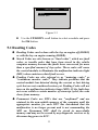
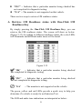
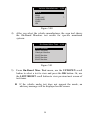
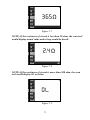
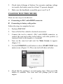
1
Table of Contents 1. SAFETY PRECAUTIONS AND WARNINGS .............................................. 1 2. GENERAL INFORMATION .......................................................................... 2 2.1 ON-BOARD DIAGNOSTICS (OBD) II ............................................................. 2 2.2 DIAGNOSTIC TROUBLE CODES (DTCS) ........................................................ 2 2.3 LOCATION OF THE DATA LINK CONNECTOR (DLC) .................................... 3 2.4 OBD II READINESS MONITORS .................................................................... 4 2.5 OBD II MONITOR READINESS STATUS ......................................................... 5 2.6 OBD II DEFINITIONS .................................................................................... 6 2.7 OBD II MODES OF OPERATION .................................................................... 7 3. USING THE SCAN TOOL ............................................................................ 10 3.1 TOOL DESCRIPTION .................................................................................... 10 3.2 SPECIFICATIONS .......................................................................................... 12 3.3 ACCESSORIES INCLUDED............................................................................. 12 3.4 NAVIGATION CHARACTERS ........................................................................ 13 3.5 KEYBOARD .................................................................................................. 13 3.6 POWER AND CHARGE................................................................................... 13 3.7 DTC LOOKUP ............................................................................................. 16 3.8 SYSTEM SETUP ............................................................................................ 17 3.9 VEHICLE COVERAGE .................................................................................. 27 3.10 PRODUCT TROUBLESHOOTING.................................................................... 27 4. REVIEW DATA ............................................................................................. 30 5. OBDII DIAGNOSTICS ................................................................................. 31 5.1 READING CODES ......................................................................................... 33 5.2 ERASING CODES .......................................................................................... 35 5.3 LIVE DATA .................................................................................................. 37 5.4 VIEWING FREEZE FRAME DATA ................................................................. 48 5.5 RETRIEVING I/M READINESS STATUS......................................................... 50 5.6 O2 MONITOR TEST ..................................................................................... 56 5.7 ON-BOARD MONITOR TEST ........................................................................ 58 5.8 COMPONENT TEST ...................................................................................... 61 5.9 VIEWING VEHICLE INFORMATION .............................................................. 63 5.10 MODULES PRESENT .................................................................................... 64 6. READY TEST ................................................................................................ 66 6.1 GENERAL INFORMATION ............................................................................ 66 6.2 READY TEST APPLICATION .......................................................................... 66 6.3 LED AND TONE INTERPRETATION .............................................................. 69 7. CIRCUIT TEST FUNCTION ....................................................................... 71 7.1 AUTO ......................................................................................................... 71 7.2 DC VOLTAGE .............................................................................................. 71 7.3 AC VOLTAGE ........................................................................................... 72 7.4 CONTINUITY ................................................................................................ 72 7.5 DIODES ........................................................................................................ 74 7.6 CURRENT .................................................................................................... 74 7.7 CURRENT .................................................................................................... 75 8. START TEST ................................................................................................. 76 8.1 STARTER TEST ............................................................................................ 76 8.2 CHARGING SYSTEM TEST ........................................................................... 80 9. BATTERY TEST ........................................................................................... 85 10. PRINT DATA ................................................................................................. 89 11. WARRANTY AND SERVICE ...................................................................... 91 11.1 LIMITED ONE YEAR WARRANTY ................................................................ 91 11.2 SERVICE PROCEDURES ................................................................................ 91 1. Safety Precautions and Warnings To prevent personal injury or damage to vehicles and/or the scan tool, read this instruction manual first and observe the following safety precautions at a minimum whenever working on a vehicle: Always perform automotive testing in a safe environment. Wear safety eye protection that meets ANSI standards. Keep clothing, hair, hands, tools, test equipment, etc. away from all moving or hot engine parts. Operate the vehicle in a well ventilated work area: Exhaust gases are poisonous. Put blocks in front of the drive wheels and never leave the vehicle unattended while running tests. Use extreme caution when working around the ignition coil, distributor cap, ignition wires and spark plugs. These components create hazardous voltages when the engine is running. Put the transmission in PARK (for automatic transmission) or NEUTRAL (for manual transmission) and make sure the parking brake is engaged. Keep a fire extinguisher suitable for gasoline/chemical/ electrical fires nearby. Don‟t connect or disconnect any test equipment while the ignition is on or the engine is running. Keep the scan tool dry, clean, free from oil/water or grease. Use a mild detergent on a clean cloth to clean the outside of the scan tool, when necessary. 1 2. General Information 2.1 On-Board Diagnostics (OBD) II The first generation of On-Board Diagnostics (called OBD I) was developed by the California Air Resources Board (ARB) and implemented in 1988 to monitor some of the emission control components on vehicles. As technology evolved and the desire to improve the On-Board Diagnostic system increased, a new generation of On-Board Diagnostic system was developed. This second generation of On-Board Diagnostic regulations is called "OBD II". The OBD II system is designed to monitor emission control systems and key engine components by performing either continuous or periodic tests of specific components and vehicle conditions. When a problem is detected, the OBD II system turns on a warning lamp (MIL) on the vehicle instrument panel to alert the driver typically by the phrase of “Check Engine” or “Service Engine Soon”. The system will also store important information about the detected malfunction so that a technician can accurately find and fix the problem. Here below follow three pieces of such valuable information: 1) Whether the Malfunction Indicator Light (MIL) is commanded 'on' or 'off'; 2) Which, if any, Diagnostic Trouble Codes (DTCs) are stored; 3) Readiness Monitor status. 2.2 Diagnostic Trouble Codes (DTCs) OBD II Diagnostic Trouble Codes are codes that are stored by the on-board computer diagnostic system in response to a problem found in the vehicle. These codes identify a particular problem area and are intended to provide you with a guide as to where a fault might be occurring within a vehicle. OBD II Diagnostic Trouble Codes consists of a five-digit alphanumeric code. The first character, a letter, identifies which control system sets the code. The other four characters, all numbers, provide additional information on where the DTC originated and the operating conditions that caused it to set. Here below is an example to illustrate the structure of the digits: 2 2.3 Location of the Data Link Connector (DLC) The DLC (Data Link Connector or Diagnostic Link Connector) is the standardized 16-cavity connector where diagnostic scan tools interface with the vehicle's on-board computer. The DLC is usually located 12 inches from the center of the instrument panel (dash), under or around the driver‟s side for most vehicles. If Data Link Connector is not located under dashboard, a label should be there telling location. For some Asian and European vehicles, the DLC is located behind the ashtray and the ashtray must be removed to access the connector. If the DLC cannot be found, refer to the vehicle‟s service manual for the location. 3 2.4 OBD II Readiness Monitors An important part of a vehicle‟s OBD II system is the Readiness Monitors, which are indicators used to find out if all of the emissions components have been evaluated by the OBD II system. They are running periodic tests on specific systems and components to ensure that they are performing within allowable limits. Currently, there are eleven OBD II Readiness Monitors (or I/M Monitors) defined by the U.S. Environmental Protection Agency (EPA). Not all monitors are supported by all vehicles and the exact number of monitors in any vehicle depends on the motor vehicle manufacturer‟s emissions control strategy. Continuous Monitors -- Some of the vehicle components or systems are continuously tested by the vehicle‟s OBD II system, while others are tested only under specific vehicle operating conditions. The continuously monitored components listed below are always ready: 1)Misfire 2)Fuel System 3)Comprehensive Components (CCM) Once the vehicle is running, the OBD II system is continuously checking the above components, monitoring key engine sensors, watching for engine misfire, and monitoring fuel demands. Non-Continuous Monitors -- Unlike the continuous monitors, many emissions and engine system components require the vehicle to be operated under specific conditions before the monitor is ready. These monitors are termed non-continuous monitors. For different ignition type engines, the available monitors are different too. 4 The following monitors are to be used for spark ignition engines only: 1) 2) 3) 4) 5) 6) 7) EGR System O2 Sensors Catalyst Evaporative System O2 Sensor Heater Secondary air Heated Catalyst The following monitors are to be used for compression ignition engines only: 1) 2) 3) 4) 5) 6) EGR System NMHC Catalyst NOx aftertreatment Boost pressure system Exhaust gas sensor PM filter 2.5 OBD II Monitor Readiness Status OBD II systems must indicate whether or not the vehicle‟s PCM‟s monitor system has completed testing on each component. Components that have been tested will be reported as “Ready”, or “Complete”, meaning they have been tested by the OBD II system. The purpose of recording readiness status is to allow inspectors to determine if the vehicle‟s OBD II system has tested all the components and/or systems. The power-train control module (PCM) sets a monitor to “Ready” or “Complete” after an appropriate drive cycle has been performed. The drive cycle that enables a monitor and sets readiness codes to “Ready” varies for each individual monitor. Once a monitor is set as “Ready” or “Complete”, it will remain in this state. A number of factors, including erasing of diagnostic trouble codes (DTCs) with a scan tool or a disconnected battery, can result in Readiness Monitors being set 5 to “Not Ready”. Since the three continuous monitors are constantly evaluating, they will be reported as “Ready” all of the time. If testing of a particular supported non-continuous monitor has not been completed, the monitor status will be reported as “Not Complete” or “Not Ready.” In order for the OBD monitor system to become ready, the vehicle should be driven under a variety of normal operating conditions. These operating conditions may include a mix of highway driving and stop and go, city type driving, and at least one overnight-off period. For specific information on getting your vehicle‟s OBD monitor system ready, please consult your vehicle owner‟s manual. 2.6 OBD II Definitions Power-train Control Module (PCM) -- OBD II terminology for the on-board computer that controls engine and drive train. Malfunction Indicator Light (MIL) -- Malfunction Indicator Light (Service Engine Soon, Check Engine) is a term used for the light on the instrument panel. It is to alert the driver and/or the repair technician that there is a problem with one or more of vehicle's systems and may cause emissions to exceed federal standards. If the MIL illuminates with a steady light, it indicates that a problem has been detected and the vehicle should be serviced as soon as possible. Under certain conditions, the dashboard light will blink or flash. This indicates a severe problem and flashing is intended to discourage vehicle operation. The vehicle onboard diagnostic system can not turn the MIL off until necessary repairs are completed or the condition no longer exists. DTC -- Diagnostic Trouble Codes (DTC) that identify which section of the emission control system has malfunctioned. Enabling Criteria -- Also termed Enabling Conditions. They are the vehicle-specific events or conditions that must occur within the engine before the various monitors will set, or run. Some monitors require the vehicle to follow a prescribed “drive cycle” routine as part of the enabling criteria. Drive cycles vary among vehicles and for each monitor in any particular vehicle. 6 OBD II Drive Cycle -- A specific mode of vehicle operation that provides conditions required to set all the readiness monitors applicable to the vehicle to the “ready” condition. The purpose of completing an OBD II drive cycle is to force the vehicle to run its onboard diagnostics. Some form of a drive cycle needs to be performed after DTCs have been erased from the PCM‟s memory or after the battery has been disconnected. Running through a vehicle‟s complete drive cycle will “set” the readiness monitors so that future faults can be detected. Drive cycles vary depending on the vehicle and the monitor that needs to be reset. For vehicle specific drive cycle, consult the vehicle‟s Owner‟s Manual. Freeze Frame Data -- When an emissions related fault occurs, the OBD II system not only sets a code but also records a snapshot of the vehicle operating parameters to help in identifying the problem. This set of values is referred to as Freeze Frame Data and may include important engine parameters such as engine RPM, vehicle speed, air flow, engine load, fuel pressure, fuel trim value, engine coolant temperature, ignition timing advance, or closed loop status. 2.7 OBD II Modes of Operation Here is a basic introduction to the OBD II communication protocol. Mode byte: The first byte in the stream is the mode number. There are 10 modes for diagnostic requests. The first byte in the response data bytes is this same number plus 64. For example, a mode 1 request would have the first data byte = 1, and the response would have the first data byte = 65. Here is a brief description of the modes: Mode $01 – Identifies the Powertrain information and shows current data available to the scan tool. This data includes: DTC set, status of on-board tests, and vehicle data such as engine RPM, temperatures, ignition advance, speed, air flow rates, and closed loop status for fuel system. Mode $02 – Displays Freeze Frame data. Same data as in mode 1, but it was captured and stored when a malfunction occurred and a DTC was set. Some of the PIDs for mode one are not implemented in this mode. 7 Mode $03 – Displays the type of powertrain or emission related DTCs stored by a 5 digit code identifying the faults. There may be more than one response message if there are more trouble codes than will fit in the data bytes of the response message, or if there are more than one ECU computer responding. Mode $04 – Used to clear DTCs and Freeze Frame data. This clears all diagnostic trouble codes that may be set including freeze frame data and readiness monitors. Mode $05 – Oxygen Sensor Test Results. This mode displays the oxygen sensor monitor screen and the test results gathered about the oxygen sensor. There are ten numbers available for diagnostics: 1. 2. 3. 4. 5. 6. 7. 8. 9. $01 Rich-to-Lean O2 sensor threshold voltage. $02 Lean-to-Rich O2 sensor threshold voltage. $03 Low sensor voltage threshold for switch time measurement. $04 High sensor voltage threshold for switch time measurement. $05 Rich-to-Lean switch time in ms. $06 Lean-to-Rich switch time in ms. $07 Minimum voltage for test. $08 Maximum voltage for test. $09 Time between voltage transitions in ms. Mode $06 – Non-continuously Monitored Systems test results. There are typically a minimum value, a maximum value, and a current value for each non-continuous monitor. This data is optional, and it is defined b a given vehicle maker if it‟s used. Mode $07 – Request for DTCs (pending) from Continuously Monitored Systems after a single driving cycle has been performed to determine if repair has fixed a problem. This used by service technicians to verify repair was performed properly and after clearing diagnostic trouble codes. 8 Mode $08 – This special Control Mode requests control of the on-board system, test, or component bi-directionally (where applicable). This mode is manufacturer specific. Mode $09 – Reports vehicle information. This information includes vehicle VIN number and calibration information stored in the vehicle ECUs. Mode $0A – Request Emission-Related Diagnostic Trouble Codes with Permanent Status. This mode is required for all emissions-related DTCs. The presence of permanent DTCs at an inspection without the MIL illuminated is an indication that a proper repair was not verified by the on-board monitoring system. 9 3. Using the Scan Tool 3.1 Tool Description 1) 2) 3) OBD II CONNECTOR – Connects the scan tool to the vehicle‟s Data Link Connector (DLC). LCD DISPLAY – Indicates test results. GREEN LED – Indicates that engine systems are running normally (The number of monitors on the vehicle which are active and performing their diagnostic testing is in the allowed limit, and no DTCs are present). 10 4) YELLOW LED – Indicates there is a possible problem. A “Pending” DTC is present and/or some of the vehicle‟s emission monitors have not run their diagnostic testing. 5) RED LED – Indicates there is a problem in one or more of the vehicle‟s systems. The red LED is also used to show that DTCs are present. DTCs are shown on the Scan Tool‟s display. In this case, the MIL lamp on the vehicle‟s instrument panel will light steady on. 6) One-Click I/M Readiness Key – Quick-checks State Emissions readiness and drive cycle verification. 7) ESC BUTTON – Cancels a selection (or action) from a menu or returns to the previous screen. 8) LEFT SCROLL BUTTON – When look up DTC definitions, moves to previous character and views additional information on previous screens if DTC definition covers more than one screen; deselect all marked PID data when viewing or recording customized live data list; views previous frames of recorded data when playing back live data. It is also used to update DTC library when pressed. 9) POWER BUTTON – Press and hold for 2 seconds to turn the scan tool on and off. Press and then release to view ? help information. 10) UP SCROLL BUTTON – Moves up through menu and submenu items in menu mode. When more than one screen of data is retrieved, moves up through the current screen to the previous screens for additional data. 11) OK BUTTON – Confirms a selection (or action) from a menu. 12) RIGHT SCROLL BUTTON – When look up DTC definitions, moves to next character and view additional information on next screens if DTC definition covers more than one screen; selects/deselects PID data when viewing or 11 recording customized live data list, and views next frames of data when playing back live data. DOWN SCROLL BUTTON – Moves down through menu and submenu items in menu mode. When more than one screen of data is retrieved, moves down through the current screen to next screens for additional data. 14) VΩ TERMINAL – Assists voltage and/or resistance test as a lead. 13) 15) COM TERMINAL – Assists test as a ground lead. 16) mA TERMINAL – Assists current (0~200mA) test as a lead. 17) A TERMINAL – Assists current (0~20A) test as a lead. 18) USB CONNECTOR – Connects the scan tool to the PC for printing and upgrading. 19) EXTERNAL DC POWER PORT – Connects the 5 volt power adapter to power the tool when disconnected from the vehicle or charge the battery. 20) STAND – Flips out for supporting the scan tool. 3.2 Specifications 1) 2) 3) 4) 5) Display: TFT color display (320 x 240 dpi) Operating Temperature: 0 to 60°C (32 to 140 F°) Storage Temperature: -20 to 70°C (-4 to 158 F°) Dimensions: Length Width Height 175 mm (6.91”) 96.6 mm (3.80”) 37 mm (1.46”) Weight: 0.3kg(without wire) 0.68kg(with wire) 3.3 Accessories Included 1) User’s Manual -- Instructions on tool operations. 12 2) 3) 4) 5) 6) CD -- Includes user‟s manual, MaxiLink update software, and etc. OBD2 cable -- Provides power to tool and communicates between tool and vehicle. USB cable -- Used to upgrade the scan tool, and to print retrieved data. 3.7V Li-ion battery -- Provides power when disconnected with vehicle. Probes -- Contacts the circuit or component to be tested. AutoLink AL539 Only: 7) Protective Nylon Case – Contains the main unit and cables while not in use. AutoLink AL539B Only: 8) 9) Battery test cable -- Used to contact the terminals of vehicle battery. Carry case -- A nylon case to store the scan tool when not in use. 3.4 Navigation Characters Characters used to help navigate the scan tool are: 1) “$” -- Identifies the control module number from which data is retrieved. Indicates the Test ID in On-Board Mon. Test. 2) “G” -- Indicates graphic viewing is available. 3.5 Keyboard No solvents such as alcohol are allowed to clean the keypad or display. Use a mild nonabrasive detergent and a soft cotton cloth. Do not soak the keypad as the keypad is not waterproof. 3.6 Power and charge Power on 13 Before using the scan tool, you must provide power to it. There are five methods for providing power to the scan tool. Cable connection to vehicle. AC/DC external power adapter. Li-ion battery. USB port. Battery test cable. During vehicle testing, power for the scan tool is usually provided through the vehicle cable connection. The detailed instructions show as below: 1) Connect the OBD II Cable to scan tool. 2) Find DLC on vehicle. A plastic DLC cover may be found for some vehicles and you need to remove it before plugging the OBD2 cable. 3) Plug OBD II cable to the vehicle‟s DLC. When the scan tool is not connected to a vehicle, it can be powered in the other three ways. Auto power-off Solely powered up by Li-ion battery, the tool will automatically turn off after 15 minutes of inactivity. Li-ion battery charging You can charge your Li-ion battery by connecting it to an external power adapter, by connecting it to the vehicle‟s DLC or by connecting it to a USB port on your computer. The tool displays a battery icon in the upper-right corner of the screen to show approximately how much charge is left. Using a Power Adapter If you're using an external power adapter, connect the tool to the adapter. Then plug the adapter into a working electrical socket. 14 Using your computer If you want to charge the tool using your computer, make sure that your computer is turned on, it isn't sleeping (refer to the computer's manual to find out how to turn sleep off), and that the USB you connect the tool to provides power. Also, make sure to use the high-powered USB ports which are typically found on the computer itself ----- not on your keyboard, which is low-powered. NOTE: If using a portable computer, make sure it is plugged into power and that the lid or display is open because if the lid is closed the computer may go into either standby, sleep, or hibernation mode and the tool will not charge. Using vehicle DLC If you want to charge the tool with vehicle DLC, the detailed instructions are described as above (refer to the Power on instructions). Using vehicle battery If you want to charge the tool with vehicle battery, use the battery test cable to connect the tool to the battery. Once connected, the Li-ion battery will be fully charged in about 2.5 hours. You can disconnect and use the tool before the battery is fully charged. You don't have to wait until the battery is completely empty before charging it again. The battery stops charging when it's full, so you don't have to worry if you leave it plugged in overnight (leaving the tool connected to an electrical source all the time doesn't continuously charge it). Once the battery is charged, disconnect the tool. If you're using your computer to charge it, make sure that you disconnect your tool correctly when it's finished charging. 15 3.7 DTC Lookup The DTC Lookup function is used to search for definitions of DTCs stored in the DTC library and for code breaker information. 1) From Main Screen (Figure 3.1), use the UP/DOWN scroll button and LEFT/RIGHT scroll button to select DTC Lookup and press the OK button. AL539 B main screen AL539 main screen Figure 3.1 2) From DTC Lookup screen, use the LEFT/RIGHT button to move to the desired character, use the UP/DOWN button to change selected digit/character and press the OK button to confirm. (Figure 3.2) DTC Lookup P0001 OK ESC Left Right Change digit Confirm Exit [ ][ ]- Change Digit [ENTER]- Figure Confirm3.2 [ESC]- Exit 3) View the DTC definition on screen. When DTC definition covers more than one screen, use the LEFT/RIGHT button or 16 UP/DOWN button to previous/next screens. view additional information on For manufacturer specific codes, you need to select a vehicle make on an additional screen to look for DTC definitions. If definition could not be found (SAE or Manufacturer Specific), the scan tool displays “Please refer to vehicle service manual!” For code breaker information, you need to press the “?” Help button. In the Code Breaker screen, there are three options to assist user to understand DTC more: System Description and Quick Check to read detailed description of DTCs, General Notes to view helpful repair information of DTCs. 4) To view previous or next DTC in the built-in DTC library, use the LEFT/RIGHT button. 5) To enter another DTC, press the ESC button to return to previous screen. 6) To exit to Main Screen, press the ESC button. 3.8 System Setup The scan tool allows you to make the following adjustments and settings: 1) Language: Selects the desired language. 2) Configure Monitors: Sets the monitors you want to test. 3) Unit of measure: Sets the unit of measure to English or Metric. 4) Key Beep Set: Turns on/off beep. 5) Status Beep Set: Turns on/off the I/M Readiness Status beep. 6) Tool Self-test: Checks if the LCD display, LED lamps and keyboard are working normally. 7) Tool Information: Views the important information of the tool. 8) Update Mode: Accesses the Update Mode. 17 Settings of the unit will remain until change to the existing settings is made. To enter the Setup menu From the Main Screen: Use the UP/DOWN scroll button and LEFT/RIGHT scroll button to select Setup, and press the OK button. Follow the instructions to make adjustments and settings as described in the above setup options. (Figure 3.3) System Setup Language Configure Monitors Unit of Measure Key Beep Set Status Beep Set Tool Self-test Tool Information 1/8 ? Figure 3.3 Language Setup English is the default language. 1) From System Setup screen, use the UP/DOWN scroll button to select Language, and press the OK button. 2) Use the UP/DOWN scroll button to select the desired language and press the OK button to save your selection and return to previous screen. We provide three language options currently. (Figure 3.4) 18 English Español Français ? Figure 3.4 Configure Monitors From System Setup screen, use the UP/DOWN scroll button to select Configure Monitors, and press the OK button. (Figure 3.5) Configure Monitors 1/4 Spark IGN Required Monitors Compression IGN Required Monitors Allowed INC Monitors ? Reset Factory Default Figure 3.5 In this menu, you could configure the monitors required to test spark ignition and compression ignition, the number of monitors to pass diagnosis, and restore the default settings. 1) Spark IGN Required Monitors From Configure Monitors screen, use the UP/DOWN scroll button to select Spark IGN Required Monitors, and press the OK button. The monitors for spark ignition engines list as below: 19 Spark IGN Required Monitors √ √ √ √ √ 2) √ √ √ √ √ MIS FUEL CCM CAT HCAT EVAP AIR O2S HTR EGR Compression IGN Required Monitors From Configure Monitors screen, use the UP/DOWN scroll button to select Compression IGN Required Monitors, and press the OK button. The monitors for compression ignition engines list as below: Compression IGN Required Monitors √ √ √ √ √ 3) √ √ √ √ MIS FUEL CCM HCCAT NCAT BP EGS PM EGR Allowed INC Monitors From Configure Monitors screen, use the UP/DOWN scroll button to select Allowed INC Monitors, and press the OK button. Emissions tests vary depending on the geographic or regional area in which the vehicle is registered. So the scan tool provides a more flexible way to meet different standards, which allows the user to select 0, 1, 2, 3 „not complete‟ monitors in test. 4) Reset Factory Default 20 From Configure Monitors screen, use the UP/DOWN scroll button to select Reset Factory Default, and press the OK button. It will restore the default configuration settings in the Configure Monitors menu, and delete any customized settings. In this case, Spark IGN Required Monitors and Compression IGN Required Monitors will include all the available monitors, and the Allowed INC Monitors will be set to 1. The tool will display an information message to ask for your confirmation. Select Yes to proceed and No to exit without change. Unit of Measure Metric is the default measurement unit. 1) From System Setup screen, use the UP/DOWN scroll button to select Unit of Measure and press the OK button. 2) From Unit of Measure screen, use the UP/DOWN scroll button to select the desired unit of measurement. (Figure 3.6 ) Unit of Measure 1/2 English Metric ? Figure 3.6 3) Press the OK button to save your selection and return to previous menu. Key Beep Set This function allows you to turn on/off the build-in speaker for key pressing. 21 The default setting is Beep On. 1) From System Setup screen, use the UP/DOWN scroll button to select Key Beep Set and press the OK button. 2) From Key Beep Set menu, use the UP/DOWN scroll button to select Beep ON or Beep OFF to turn on/off the beep. Key Beep Set 1/2 Beep ON Beep OFF ? Figure 3.7 3) Press the OK button to save your selection and return to previous menu. Status Beep Set The default setting is Beep On. This function allows you to turn on/off the build-in speaker for the LEDs in diagnostic testing. Different audio tone corresponds to different LED lamp. This function is invaluable when performing diagnostics alone, or working in bright areas where LED illumination alone is not sufficient. 1) From System Setup screen, use the UP/DOWN scroll button to select Status Beep Set and press the OK button. 2) From Status Beep Set menu, use the UP/DOWN scroll button to select Beep ON or Beep OFF to turn on/off the beep. (Figure 3.8) 22 Status Beep Set 1/2 Beep ON Beep OFF ? Figure 3.8 3) Press the OK button to save your selection and return to previous menu. Tool Self-test The Tool Self-test function checks if the display, LED lamps and keyboard are working properly. A. Display test The Display Test function checks if the LCD display is working normally. 1) From System Setup screen, use the UP/DOWN scroll button to select Tool Self-test, and press the OK button. 2) Select Display Test from Tool Self-test menu and press the OK button to start test. (Figure 3.9 ) Tool Self-test Display Test Keyboard Test LED Test 1/3 ? Figure 3.9 3) Look for missing spots in the red, green, blue, black and white LCD display. 23 4) B. When completed, press the ESC button to exit. Keyboard Test The Keyboard Test function verifies if the keys are functioning properly. 1) Use the UP/DOWN scroll button to select Keyboard Test from the Tool Self-test menu, and then press the OK button. 2) Press any key to start test. When you press a key, the key name should be observed on the display. If the key name does not show up, then the key is not functioning properly. (Figure 3.10) Keyboard Test Press any key to start test key: Double [ESC] to return Figure 3.10 3) C. Double press ESC to return to previous menu. LED Test The LED Test function verifies if the I/M Readiness LED indicator lamps are functioning properly. 1) Use the UP/DOWN scroll button to select LED Test from the Tool Self-test menu, and then press the OK button. 2) In the LED Test menu, use the UP/DOWN scroll button to select one or more LED lamps to check. The LED should turn on or off according to the selected commands. (Figure 3.11) 24 LED Test 1/3 RED LED ON YELLOW LED ON GREEN LED ON Figure 3.11 3) When completed, press the ESC button to exit Tool Information The Tool Information function allows viewing of some important information such as serial number and software version number of the scanner. 1) From System Setup screen, use the UP/DOWN scroll button to select Tool Information, and press the OK button; wait for the Tool Information screen to appear. 2) View tool information on screen. (Figure 3.12) . Figure 3.12 25 Update Mode This function allows you to update the scan tool software and DTC library through a computer. To update your scan tool, you need the following items. AutoLink AL539 A PC or laptop with USB ports A USB cable 1) Download the programs in our website, www. auteltech.com, to be updated to your computer. 2) Run the Maxi Link II Tool Kit in your computer. (Figure 3.13) 3) Connect the scan tool to your computer through the USB cable provided. 4) From System Setup screen in scan tool, use the UP/DOWN scroll button to select Update Mode, and press the OK button. 5) Select the programs to be updated in your computer. There are two types of programs: operating system and DTC library. (Figure 3.13) 6) Click Update in the MaxiLink Tool Kit window to begin updating. Figure 3.13 26 7) During the update procedure, the scan tool displays a message “Update Program. Please wait…”. 8) When the update has finished, the scan tool will display a message “Program Update has been done!” 9) Restart the scan tool to finish the whole update. NOTE: When you made a wrong choice and the scan tool is unable to work properly, you may need to update the programs. To hold LEFT scroll button and power on the scan tool, you will enter the Update Mode forcedly. Then follow the update procedure to refresh the program. 3.9 Vehicle Coverage The AutoLink AL539 OBDII/EOBD Scanner is specially designed to work with all OBD II compliant vehicles, including those equipped with universal protocol -- Control Area Network (CAN). It is required by EPA that all 1996 and newer vehicles (cars and light trucks) sold in the United States must be OBD II compliant and this includes all Domestic, Asian and European vehicles. A small number of 1994 and 1995 model year gasoline vehicles are OBD II compliant. To verify if a 1994 or 1995 vehicle is OBD II compliant, check the Vehicle Emissions Control Information (VECI) Label which is located under the hood or by the radiator of most vehicles. If the vehicle is OBD II compliant, the label will designate “OBD II Certified”. Additionally, Government regulations mandate that all OBD II compliant vehicles must have a “common” sixteen-pin Data Link Connector (DLC). For your vehicle to be OBD II compliant it must have a 16-pin DLC (Data Link Connector) under the dash and the Vehicle Emission Control Information Label must state that the vehicle is OBD II compliant. 3.10 Product Troubleshooting 27 This part describes problems that you may encounter while using the scan tool. Vehicle Linking Error A communication error occurs if the scan tool fails to communicate with the vehicle‟s ECU (Engine Control Unit). You need to do the following to check up: Verify that the ignition is ON. Check if the scan tool‟s connector is securely connected to the vehicle‟s DLC. Verify that the vehicle is OBD2 compliant. Turn the ignition off and wait for about 10 seconds. Turn the ignition back to on and continue the testing. Verify the control module is not defective. Operating Error If the scan tool freezes, then an exception occurs or the vehicle‟s ECU (Engine Control Unit) is too slow to respond to requests. You need to do the following to reset the tool: Reset the scan tool. Turn the ignition off and wait for about 10 seconds. Turn the ignition back to on and continue the testing. Scan tool doesn’t power up If the scan tool won‟t power up or operates incorrectly in any other way, you need to do the following to check up: Check if the scan tool‟s connector is securely connected to the vehicle‟s DLC; Check if the DLC pins are bent or broken. Clean the DLC pins if necessary. Check vehicle battery to make sure it is still good with at least 8.0 volts. LED lamps not working 28 If you turn on the scan tool and perform the I/M Readiness test but the LED lamps are not working, there may be several possible causes, including bad connection and ignition off. In this case, follow these steps to check the scan tool. Make sure the cable is connected to the DLC securely. Verify the ignition key is in the KOER position. Run the LED Test in the System Setup menu. (see 3.8 System Setup). If the scan tool did not pass this test, there is a problem with the LED lamp. Please contact Autel Tech Support or your local selling agent. 29 4. Review Data The Review Data function allows viewing of data from last test recorded by the scan tool. 1) Use the UP/DOWN scroll button and LEFT/RIGHT scroll button to select Review Data from Main Screen, and press the OK button. (Figure 3.1) 2) Use the UP/DOWN scroll button to select the desired item from Review Data menu, and press the OK button. (Figure 4.1 ) Review Data 1/6 Live Data Pending Codes View Freeze Frame I/M Readiness On-Board Mon. Test Modules Present ? Figure 4.1 3) If no data from previously tested vehicle is recorded, the scan tool displays a message, “No data available!”. Diagnostics results can be reviewed from this list only when any trouble code is detected in previous tests. Review selected data on screen. (Figure 4.2 ) 1/1 C1201 Engine Control System Malfunction Figure 4.2 NOTE: If there is no data stored for selected item, a “Not Supported or Stored No Data!” message shows on the screen. 30 5. OBDII Diagnostics When more than one vehicle control module is detected by the scan tool, you will be prompted to select the module where the data may be retrieved. The most often to be selected are the Power train Control Module [PCM] and Transmission Control Module [TCM]. CAUTION: Don’t connect or disconnect any test equipment with ignition on or engine running. 1) 2) 3) 4) 5) Turn the ignition off. Locate the vehicle‟s 16-pin Data Link Connector (DLC). Plug the scan tool cable connector into the vehicle‟s DLC. Turn the ignition on. Engine can be off or running. Turn on the scan tool. Use the UP/DOWN scroll button to select OBDII/EOBD from the Main Screen (Figure 3.1). 6) Press the OK button to wait for the Menu to appear. A sequence of messages displaying the OBDII protocols will be observed on the display until the vehicle protocol is detected. If the scan tool fails to communicate with the vehicle’s ECU (Engine Control Unit) more than three times, a “LINKING ERROR!” message shows up on the display. Verify that the ignition is ON; Check if the scan tool‟s OBD II connector is securely connected to the vehicle‟s DLC; Verify that the vehicle is OBD2 compliant; Turn the ignition off and wait for about 10 seconds. Turn the ignition back to on and repeat the procedure from step 5. If the “LINKING ERROR” message does not go away, then there might be problems for the scan tool to communicate with the vehicle. Contact your local distributor or the manufacturer’s customer service department for assistance. 7) You will be prompted to erase previously stored data. (Figure 5.1) 31 Review previously stored data thoroughly before erasing. Diagnostic Erase previously stored data to save data from this test? YES NO Figure 5.1 If no data is stored in the scan tool, above prompt will not show up. 8) If you wish to erase the data, press the OK button; if you do not want to erase the data, press ESC to exit or use LEFT/RIGHT button to select NO and press OK to continue. 9) View a summary of system status (MIL status, DTC counts, Monitor status) on screen. (Figure 5.2 ) Wait a few seconds or press any key for Diagnostic Menu (Figure 5.4) to come up. System Status MIL Status ON Codes Found 6 Ignition Type Spark Monitors N/A 3 Monitors OK 3 Monitors INC 5 Figure 5.2 If more than one module is detected, you will be prompted to select a module before testing. 32 Control Module 1/2 Engine Module $A4 Figure 5.3 Use the UP/DOWN scroll button to select a module and press the OK button. 5.1 Reading Codes Reading Codes can be done with the key on engine off (KOEO) or with the key on engine running (KOER). Stored Codes are also known as “hard codes”, which are fault codes, or trouble codes that have been stored in the vehicle computer memory because the faults have reoccurred for more than a specified amount of key-cycles. These codes will cause the control module to illuminate the malfunction indicator light (MIL) when emission-related fault occurs. Pending Codes are also referred to as “maturing codes” or “continuous monitor codes”. They indicate problems that the control module has detected during the current or last driving cycle but are not considered serious yet. Pending Codes will not turn on the malfunction indicator lamp (MIL). If the fault does not occur within a certain number of warm-up cycles, the code clears from memory. Permanent Codes are DTCs that are "confirmed" and are retained in the non-volatile memory of the computer until the appropriate monitor for each DTC has determined that the malfunction is no longer present and is not commanding the MIL on. Permanent DTC shall be stored in non-volatile memory and may not be erased by any diagnostic services or by disconnecting power to ECU. 33 1) Use UP/DOWN scroll button to select Read Codes from Diagnostic Menu and press OK button. Diagnostic Menu 1/11 Read Codes Erase Codes Live Data View Freeze Frame I/M Readiness O2 Monitor Test ? Figure 5.4 2) Use the UP/DOWN scroll button to select Stored Codes or Pending Codes from the Read Codes menu and press the OK button. Read Codes 1/3 Stored Codes Pending Codes Permanent Codes ? Figure 5.5 If there is not any Diagnostic Trouble Code, the display indicates “No (pending) codes are stored in the module!” Wait a few seconds or press any key to return to previous screen. NOTE: Permanent Codes function is available for merely vehicles supporting the CAN protocols. 3) View DTCs and their definitions on screen. 34 1/1 P1633 $10 BUICK Ignition 0 Switch Circuit Figure 5.6 4) If more than one DTC is found, use the LEFT/RIGHT scroll button to check all the codes. If retrieved DTCs contain any manufacturer specific or enhanced codes, a “Manufacturer specific codes are found! Press any key to select vehicle make!” message comes up prompting you to select vehicle manufacturer to view DTC definitions. Use UP/DOWN scroll button to select manufacturer and then press OK button to confirm. Vehicle Manufacturer 1/28 BUICK BMW CADILLAC CHEVROLET CHRYSLER FORD ? Figure 5.7 If the manufacturer of your vehicle is not listed, use the UP/DOWN scroll button to select Other and press the OK button. 5.2 Erasing Codes CAUTION: Erasing the Diagnostic Trouble Codes may allow the scan tool to delete not only the codes from the vehicle’s on-board computer, but also “Freeze Frame” data and manufacturer specific 35 enhanced data. Further, the I/M Readiness Monitor Status for all vehicle monitors is reset to Not Ready or Not Complete status. Do not erase the codes before the system has been checked completely by a technician. NOTE: Erasing codes does not mean that trouble codes in ECU have been eliminated completely. As long as there is fault with the vehicle, the trouble codes keeps on presenting. This function is performed with key on engine off (KOEO). Do not start the engine. 1) Use the UP/DOWN scroll buttons to select Erase Codes from Diagnostics Menu and press the OK button. (Figure 5.4) 2) A warning message comes up asking for your confirmation. Erase Codes Erase trouble codes! Are you sure? YES NO Figure 5.8 If you do not want to proceed with erasing codes, press ESC button or use LEFT/RIGHT scroll button to select NO to exit. A message of “Command Cancelled!” show ups. Wait a few seconds or press any key to return to Diagnostic Menu. 3) Press the OK button to confirm. If the codes are cleared successfully, an “Erase Done!” confirmation message shows on the display. 36 Erase Codes Erase Done! Press any key to con. Figure 5.9 If the codes are not cleared, then an “Erase Failure. Turn Key on with Engine off!” message appears. Erase Codes Erase Failure. Turn Key on with Engine Off! Press any key to con. Figure 5.10 4) Press any button to return to Diagnostic Menu. 5.3 Live Data In this function, you can not only read the live data but also record data for later review. Viewing Data The View Data function allows viewing of live or real time PID data of vehicle’s computer module(s). 1) To view live data, use the UP/DOWN scroll button to select Live Data from Diagnostic Menu and press the OK button. (Figure 5.4) 37 2) Wait a few seconds while the scan tool validates the PID MAP. (Figure 5.11) Live Data Reading PID.01 - Please Wait - Figure 5.11 3) Use the UP/DOWN scroll button to select View Data from Live Data menu and press the OK button. ……………… .Live Data View Data Record Data Playback Data 1/3. ? Figure 5.12 Viewing Complete Data Set 1) To view complete set of data, use UP/DOWN scroll button to select Complete Data Set from View Data menu and press the OK button. 38 …………………View Data 1/3. Complete Data Set Custom Data Set Unit of Measure ? Figure 5.13 2) View live PIDs on the screen. Use the UP/DOWN scroll button for more PIDs if additional information is available on more than one page. Live Data DTC_CNT FUELSYS1 FUELSYS2 LOAD_PCT (%) ETC(℃) SHRTFT1 (%) 6 0 0L -- ? 0.0 -40 99.2 Figure 5.14 The number “x” to the right of the screen indicates sequence of the highlighted item. If the “G” icon appears when a PID is highlighted, graphic information is available. Press OK to view graph. Figure 5.15 39 3) Press the ESC button to return to previous menu. Viewing Custom Data Set 1) To view customized PID data, use the UP/DOWN scroll button to select Custom Data Set from View Data menu and press the OK button. (Figure 5.13) 2) Observe on-screen instructions. ……………Custom Data Set……… ….. [ ] – Select/Deselect [ ] – Deselect all [OK] – Confirm [ESC] – Cancel Press any key to continue. Figure 5.16 3) Use the RIGHT button to deselect/select data parameters, and use the UP/DOWN scroll button to move up and down. Selected parameters are marked with solid squares. …………..Custom Data Set DTC_CNT FUELSYS1 FUELSYS2 LOAD_PCT ECT SHRTFT1 4/26 #01 ? Figure 5.17 The number “x” to the upper right corner of the screen indicates sequence of highlighted item; and “#x” are the order that the parameters are selected and will be displayed. 40 If you want to deselect all marked items or select all items, press the LEFT button. A message comes up to ask for your confirmation. ………………Deselect All…………………. Deselect all selected PID’s? YES NO Figure 5.18 4) If you decide to deselect these items, press OK; if you decide not to, press ESC or use the LEFT/RIGHT scroll button to select NO to continue PID selections. Press the OK button to view selected PIDs on screen. ………………….Live Data DTC_CNT FUELSYS2 ETC(℃) SHRTFT1 (%) 4. 0 0L -40 99.2 Figure 5.19 5) Use the ESC button to return to previous menu. Recording Data The Record Data function allows recording vehicle modules’ Parameter Identification (PID) data to help diagnose intermittent vehicle problems. A recording includes 5 frames of live data before trigger event and several frames after trigger event. 41 There are two trigger modes used to record data: A. Manual Trigger - allows user to press the OK button to start recording. B. DTC Trigger - automatically records PID data when a fault that causes a DTC to set is detected by vehicle. CAUTION: DO NOT try to drive and operate the scan tool at the same time! Always have another person operate the scan tool while driving. To record live data, use the UP/DOWN scroll button to select Record Data from Live Data menu and press the OK button. (Figure 5.12) Recording Complete Data Set 1) To record complete set of live data, use the UP/DOWN scroll button to select Complete Data Set from Record Data menu and press the OK button. ………………..Record Data Complete Data Set Custom Data Set Unit of Measure 1/3.. ? Figure 5.20 2) Use the UP/DOWN scroll button to select a trigger mode and press the OK button. 42 …….……Pick Trigger Mode 1/2 Manual Trigger DTC Trigger ? Figure 5.21 3) If data from previously tested vehicle is not erased, data from current test will be stored in a temporary cache. Use the UP/DOWN scroll button to select a memory location and press the OK button. …………….Select Memory Location #1 Location #2 Location #3 1/3.. * ? Figure 5.22 The asterisk (*) icon on the screen indicates that there is a previous recording in the memory location. If you select a location marked with an asterisk (*) icon, a message prompting to overwrite old recording displays. Select Memory A previous recording exists! Do you want to overwrite it? YES NO Figure 5.23 43 ... 4) If you wish to proceed with overwriting the old recording, press the OK button; if you do not wish to overwrite it, use the LEFT/RIGHT button to select NO or press the ESC button to pick another memory location. Observe on-screen instructions. If Manual Trigger is selected, following screen shows: ……………Manual Trigger……………... Ready to record! Press [ENTER] to start recording… Press [ESC] to exit Figure 5.24 If DTC Trigger is selected, following screen shows: ………………….DTC Trigger…………….. Waiting for DTC to trigger recording… Press [ESC] to exit Figure 5.25 5) Wait for DTC to trigger recording or press OK to start recording. (Figure 5.26) Drive till a DTC is detected when DTC Trigger is selected. If no DTCs are detected, press ESC to exit recording. 44 …….Recording…. 5/46 ….. DTC_CNT FUELSYS1 FUELSYS2 LOAD_PCT(%) ETC(℃) SHRTFT1(%) 0 0L -- ? 0.0 -40 99.2 Figure 5.26 6) The number “x/x...” to the upper right corner of the screen indicates the maximum frames that can be recorded and the number of recorded frames. The scan tool keeps recording PID data until user presses the ESC button, selected memory location is full, or it completes recording. A message prompting to playback data shows on the screen. Record Data Recording Done! Playback data? YES NO Figure 5.27 If you wish to playback recorded data, press the OK button; if you do not wish to playback, press the ESC button, or use LEFT/RIGHT button to select NO and press the OK button to return to Record Data menu. Recording Custom Data Set 1) To record customized data, use the UP/DOWN scroll button to select Custom Data Set from Record Data menu and press the OK button. (Figure 5.20) 45 2) Observe on-screen instructions. (Figure 5.16). Press the OK button to continue; press the ESC button, or use LEFT/RIGHT button to select NO and press the OK button to return to Record Data menu. 3) Use the RIGHT button select/deselect data parameters. Selected parameters are marked with solid squares. Press the OK button to confirm. (Figure 5.17) 4) If you wish to deselect all marked items, press LEFT button. A message comes up to ask for your confirmation.( Figure 5.18) If you decide to deselect these items, press OK; if you decide not to, press the ESC button, or use the UP/DOWN button to select NO and press OK to continue PID selections. Use the UP/DOWN scroll button to select a trigger mode and press the OK button.( Figure 5.21) 5) Use the UP/DOWN scroll button to select a memory location and press the OK button.( Figure 5.22) 6) If data from previously tested vehicle is not erased, data from current test will be stored in temporary cache. The asterisk (*) icon on the screen indicates that there is a previous recording in the memory location. If you select a location marked with an asterisk (*) icon, a message prompting to overwrite old recording is displayed.( Figure 5.23) If you do not wish to proceed with overwriting old recording, press the OK button; if you do not wish to overwrite it, press the ESC button, or use the LEFT/RIGHT button to select NO and press OK to pick another memory location. Observe on-screen instructions. 46 If Manual Trigger is selected, following screen shows: (Figure 5.24) If DTC Trigger is selected, following screen shows: (Figure 5.25) 7) Wait for DTC to trigger recording or press OK to start recording. (Figure 5.26) 8) The scan tool keep recording PID data until user presses ESC button, the selected memory location is full, or it completes recording. A message prompting to playback data shows on the screen. (Figure 5.27) If you wish to playback recorded data, press the OK button; if you do not wish to playback, press the ECS button, or use the LEFT/RIGHT button to select NO and press the OK button to return to Record Data menu. Playback Data The Playback Data function allows viewing of previously stored PID data. 1) To playback recorded data, use the UP/DOWN scroll button to select Playback Data from Live Data menu and press the OK button. (Figure 5.12) 2) You are also allowed to playback recorded data immediately after recording. Use the UP/DOWN button to select the memory location marked with an asterisk (*) icon. 47 Select Memory Location #1 Location #2 Location #3 3/3 * * ? Figure 5.28 3) If there is no recording in selected location, a message “Not Supported or Stored No Data” displays on the screen. Use the UP/DOWN button to view recorded PIDs of each frame. 1 of 135 frame DTC_CNT FUELSYS1 FUELSYS2 LOAD_PCT (%) ETC(℃) SHRTFT1(%) … 6 0 OL N/A ? 0.0 -40 99.2 Figure 5.29 4) Use the LEFT/RIGHT button to view PIDs of next or previous frames. 6 of 135 frame DTC_CNT FUELSYS1 FUELSYS2 LOAD_PCT(%) ETC(℃) SHRTFT1(%) Figure 5.30 5.4 Viewing Freeze Frame Data 48 0 OL N/A 0.0 -40 99.2 4 ? Freeze Frame Data allows the technician to view the vehicle‟s operating parameters at the moment a DTC (Diagnostic Trouble Code) is detected. For example, the parameters may include engine speed (RPM), engine coolant temperature (ECT), or vehicle speed sensor (VSS) etc. This information will aid the technician by allowing the parameters to be duplicated for diagnostic and repair purposes. 1) To view freeze frame data, use the UP/DOWN scroll button to select View Freeze Frame from Diagnostic Menu and press the OK button. (Figure 5.4) 2) Wait a few seconds while the scan tool validates the PID MAP. 3) If retrieved information covers more than one screen, use the DOWN scroll button, as necessary, until all the data have been shown up. …………View Freeze Frame DTCFRZF FUELSYS1 FUELSYS2 LOAD_PCT (%) ECT(℃) SHRTFT1 (%) P1633 OL -0.0 -40 99.2 2. ? Figure 5.31 4) If there is no freeze frame data available, an advisory message “No freeze frame data stored!” shows on the display. If you want to view full name of a PID, use the UP/DOWN scroll button to select the PID, and press the ? HELP button. 49 ……………… ..FUELSYS1……… ……. Fuel System 1 Status Figure 5.32 5) Press ESC button to return to previous screen. 5.5 Retrieving I/M Readiness Status I/M Readiness function is used to check the operations of the Emission System on OBD2 compliant vehicles. It is an excellent function to use prior to having a vehicle inspected for compliance to a state emissions program. CAUTION - by clearing trouble codes you also clear the readiness status for the individual emission system readiness tests. In order to reset these monitors, the vehicle must be driven through a complete drive cycle with no trouble codes in memory. Times for reset vary depending on vehicle. Some latest vehicle models may support two types of I/M Readiness tests: A. B. Since DTCs Cleared - indicates status of the monitors since the DTCs are erased. This Drive Cycle - indicates status of monitors since the beginning of the current drive cycle. An I/M Readiness Status result of “NO” does not necessarily indicate that the vehicle being tested will fail the state I/M inspection. For some states, one or more such monitors may be allowed to be “Not Ready” to pass the emissions inspection. “OK” -- Indicates that a particular monitor being checked has completed its diagnostic testing. 50 “INC” -- Indicates that a particular monitor being checked has not completed its diagnostic testing. “N/A” -- The monitor is not supported on that vehicle. There are two ways to retrieve I/M readiness status. A. Retrieve I/M Readiness status with One-Click I/M Readiness Key By simply pressing the One-Click I/M Readiness Key, you can retrieve the I/M readiness status. The screen will show as below. (Figure 5.33) According to different readiness status, the color LEDs will illuminate and different audio tones will be heard. Figure 5.33 “OK” -- Indicates that a particular monitor being checked has completed its diagnostic testing. “INC” -- Indicates that a particular monitor being checked has not completed its diagnostic testing. “N/A” -- The monitor is not supported on the vehicle. The green, yellow and red LEDs provide a quick way to help you determine if a vehicle is ready for an Emission Test. The LED and audio tone indications are interpreted as below: 51 LED Interpretation 1) GREEN LED – Indicates that engine systems are “OK” and operating normally (the number of Monitors supported by the vehicle which have run and performed their self-diagnostic testing is in the allowed limit. MIL is off. ).There are no stored and pending DTCs. The vehicle is ready for an Emissions Test, and there is a good possibility that it can be certified. 2) YELLOW LED – With MIL off, there may be three possible conditions to cause the yellow LED to light. If a “Stored” Diagnostic Trouble Code is causing the Yellow LED to light, it is still possible that the vehicle will be allowed to be tested for emissions and certified. If a “Pending” Diagnostic Trouble Code is causing the Yellow LED to light, it is still possible that the vehicle will be allowed to be tested for emissions and certified. If the illumination of the Yellow LED is being caused by monitors that have not completed their diagnostic testing, then the issue of the vehicle being ready for an Emissions Test depends on the emissions regulations and laws of your local area. NOTE: From the code retrieval procedure, determine the status of each Monitor. Take this information to an emissions professional to determine (based on your test results) if your vehicle is ready for an Emissions Test. 3) RED LED – Indicates there is a problem with one or more of the vehicle‟s system. A vehicle displaying a red LED is definitely not ready for an Emissions Test. The red LED is also an indication that there are DTCs present. The MIL lamp on the vehicle‟s instrument panel will light steady. The problem that is causing the red LED to light must be repaired before an 52 Emissions Test can be performed. It is also suggested that the vehicle be inspected/repaired before driving the vehicle further. If the RED LED was obtained, there is a definite problem present in the system(s). In these cases, you have the following options: Repair the vehicle yourself. If you are going to perform the repairs yourself, proceed by reading the vehicle service manual and following all its procedures and recommendations. Take the vehicle to a professional to have it serviced. The problem(s) causing the red LED to light must be repaired before the vehicle is ready for an Emissions Test. Audio Tone Interpretation The audio tone is configured according to the I/M Readiness Status. This function is invaluable when performing diagnostics and driving at the same time , or working in bright areas where LED illumination alone is not sufficient. Different audio tone with different LED light indicates different I/M Readiness Status. LED Light Audio Tone Beep Interval Green LED Two long beeps 5 seconds Yellow LED short, long, short beep 5 seconds Four short beeps 5 seconds Red LED After you have read the information, press ESC to exit. The other buttons are disabled to prevent misoperation. B. Retrieve I/M Readiness status in typical way 53 1) Use the UP/DOWN scroll button to select I/M Readiness from Diagnostic Menu and press OK button. (Figure 5.4) 2) Wait a few seconds while the scan tool validates the PID MAP. 3) If the vehicle supports both types of tests, then both types will be shown on the screen for selection. ……………I/M Readiness 1/2. Since DTCs Cleared This Drive Cycle Figure 5.34 4) Use the UP/DOWN scroll button, as necessary, to view the status of the MIL light (“ON” or “OFF) and the following monitors. For spark ignition engines: MIS -- Misfire Monitor FUEL -- Fuel System Monitor CCM -- Comprehensive Component Monitor EGR – EGR System Monitor O2S -- O2 Sensors Monitor CAT -- Catalyst Monitor EVAP -- Evaporative System Monitor HTR -- O2 Sensor Heater Monitor AIR -- Secondary Air Monitor HCAT -- Heated Catalyst Monitor For compression ignition engines: MIS -- Misfire Monitor FUEL -- Fuel System Monitor 54 CCM -- Comprehensive Component Monitor EGR – EGR System Monitor HCCAT -- NMHC Catalyst Monitor NCAT -- NOx Aftertreatment Monitor BP -- Boost Pressure System Monitor EGS -- Exhaust Gas Sensor Monitor PM -- PM Filter Monitor …………Since DTCs Cleared MIL MIS FUEL CCM CAT HCAT 1 OFF OK OK ? OK INC N/A Figure 5.35 5) If the vehicle supports readiness test of “This Drive Cycle”, a screen of the following displays: …………..This Drive Cycle MIL MIS FUEL CCM CAT HCAT 1. OFF OK N/A ? OK INC N/A Figure 5.36 6) The LEDs and audio tone corresponding to different monitor status will be activated as below. 55 LED Light Audio Tone Beep Interval Green LED Two long beeps 2 minutes Yellow LED short, long, short beep 2 minutes Four short beeps 2 minutes Red LED 7) Use the UP/DOWN scroll button for more PIDs if additional information is available on more than one page. Or use the LEFT/RIGHT scroll button to view PIDs in the previous/next page. 8) Press the ESC button to return to Diagnostic Menu. 5.6 O2 Monitor Test OBD2 regulations set by SAE require that relevant vehicles monitor and tests on the oxygen (O2) sensors to identify problems related to fuel efficiency and vehicle emissions. These tests are not on-demand tests and they are done automatically when engine operating conditions are within specified limits. These test results are saved in the on-board computer's memory. The O2 Monitor Test function allows retrieval and viewing of O2 sensor monitor test results for the most recently performed tests from the vehicle's on-board computer. The O2 Monitor Test function is not supported by vehicles which communicate using a controller area network (CAN). For O2 Monitor Test results of CAN-equipped vehicles, see 5.7 “On-Board Monitor Test”. 1) Use the UP/DOWN scroll button to select O2 Monitor Test from Diagnostic Menu and press OK button. (Figure 5.4) 2) Wait a few seconds while the scan tool validates the PID MAP. 3) Use the UP/DOWN scroll button to select O2 sensor from O2 Monitor Test menu and press OK button. 56 ............O2 Monitor Test O2 Bank1 Sensor1 O2 Bank1 Sensor2 O2 Bank1 Sensor3 2/8… ? Figure 5.37 If the vehicle does not support the mode, an advisory message will be displayed on the screen. …………….O2 Monitor Test………….. The selected mode is not supported! Figure 5.38 4) View test results of selected O2 sensor. … ……….O2 Bank1 Sensor2 1/31. Rich-Lean Threshd V Lean-Rich Threshd V $70(counts) $71(counts) $83 $84 Figure 5.39 5) Use the UP/DOWN scroll button to view more screens of data if additional information is available in more than one page. 57 6) Press the ESC button to return to the previous menu. 5.7 On-Board Monitor Test The On-Board Monitor Test is useful after servicing or after erasing a vehicle’s control module memory. The On-Board Monitor Test for non-CAN-equipped vehicles retrieves and displays test results for emission-related power train components and systems that are not continuously monitored. The On-Board Monitor Test for CAN-equipped vehicles retrieves and displays test results for emission-related power train components and systems that are and are not continuously monitored. The scan tool allows access to the results of on-board diagnostic monitoring tests for specific components/systems. The vehicle manufacturer is responsible for assigning "Manufacturer Defined Test IDs" and Component IDs for tests of different systems and components. The advanced feature of this scan tool enables you to read the definition of an On-Board Diagnostic Monitor ID. NOTE: The scan tool will display a Test definition only if this test definition is present in the vehicle’s computer memory. If no such definition is present, the scan tool will just display the Test IDs. In this test, there are typically a minimum value, a maximum value, and a current value for each monitor. By comparing the current value with the minimum and maximum value, the scan tool will determine if it is OK. 1) Use the UP/DOWN scroll button to select On-Board Mon. Test from Diagnostic Menu and press the OK button. (Figure 5.4) 2) Wait a few seconds while the scan tool validates the PID MAP. 3) The scan tool will prompt you to select the vehicle make. 58 Vehicle Manufacturer 1/28 BUICK BMW CADILLAC CHRYSLER FORD GM ? Figure 5.40 4) After you select the vehicle manufacturer, the scan tool shows the On-Board Monitors test results for specific monitored systems. On-Board Mon. Test 1/19 HO2S Monitor HO2S Monitor Catalyst Monitor EVAP Monitor EVAP Monitor EVAP Monitor Figure 5.41 5) From On-Board Mon. Test menu, use the UP/DOWN scroll button to select a test to view and press the OK button. Or, use the LEFT/RIGHT scroll button to view previous/next screen of test items. If the vehicle under test does not support the mode, an advisory message will be displayed on the screen. 59 On-Board Mon. Test The selected mode is not supported Press any key to con.. Figure 5.42 For CAN-equipped vehicles, test selections can be as below: On-Board Mon. Test 1/31.. O2 Mon. B1S1 O2 Mon. B1S2 O2 Mon. B1S3 O2 Mon. B1S4 O2 Mon. B2S1 O2 Mon. B2S2 Figure 5.43 6) Use the UP/DOWN scroll button to select the desired monitor from On-Board Mon. Test menu and press the OK button. 7) View test data on screen. HO2S11 Voltage amplitu 1/36 ID MOD TEST(volts) MIN(volts) MAX(volts) STS 11 $10 400 1E1 ----OK Figure 5.44 60 ? NOTE: If the On-Board Monitor Test failed, this monitor item will be red color. Just by the text color you may easily find out which system is at fault. EVAP monitor Phase 0 Initial tank vacuum an.. Figure 5.45 Phase 0 Initial tank vacuum ID MOD TEST(in H2O) MIN(in H2O) MAX(in H2O) STS 00 $10 0000 7000 7200 Fail 1 ? Figure 5.46 8) Press ESC button to return to the previous menus. 5.8 Component Test The Component Test function allows initiating a leak test for the vehicle's EVAP system. The scan tool itself does not perform the leak test, but commands the vehicle's on-board computer to start the test. Different vehicle manufacturers might have different criteria and methods for stopping the test once it has been started. Before starting the Component Test, refer to the vehicle service manual for instructions to stop the test. 1) Use the UP/DOWN scroll button to select Component Test from Diagnostic Menu and press the OK button. (Figure 5.4) 61 2) Wait for the scan tool to display the Component Test menu. Component Test Evap Leak Test ? Figure 5.47 3) If the test has been initiated by the vehicle, a confirmation message will be displayed on the screen. Component Test Command Sent! Press any key to con. Figure 5.48 Some vehicles do not allow scan tools to control vehicle systems or components. If the vehicle under test does not support the EVAP Leak Test, an advisory message is displayed on the screen. .............Component Test The selected mode is not supported Press any key to con. Figure 5.49 62 4) Wait a few seconds or press any key to return to previous screen. 5.9 Viewing Vehicle Information The Vehicle Info. function enables retrieval of Vehicle Identification No. (VIN), Calibration ID Nos. (CINs), Calibration Verification Nos. (CVNs) and In-use Performance Tracking on 2000 and newer vehicles that support Mode 9. 1) Use UP/DOWN scroll button to select Vehicle Info. from the Diagnostic Menu and press OK button. (Figure 5.4) 2) An advisory message comes up to remind you. Wait a few seconds or press any key to continue. Vehicle Info. Turn key on with engine off ! Press any key to con. Figure 5.50 3) Wait a few seconds while the scan tool reads vehicle information. Vehicle Info. Reading info… - Please Wait - Figure 5.51 If the vehicle does not support this mode, a message shows on the display warning that the mode is not supported. 63 4) From Vehicle Info. Menu, use the UP/DOWN scroll button to select an available item to view and press the OK button. Vehicle Info. 3/3 Vehicle ID Number Calibration ID Cal. Verf. Number ? Figure 5.52 5) View retrieved vehicle information on screen. Cal. Verf. Number CVN1: BB BA A0 78 ? Figure 5.53 6) Press the ESC button to return to previous menu. 5.10 Modules Present The Modules Present function allows viewing of the module IDs and communication protocols for OBD2 modules in the vehicle. 1) Use the UP/DOWN scroll button to select Modules Present from Diagnostic Menu and press OK button. (Figure 5.4) 2) View modules present with their IDs and communication protocols. 64 Modules Present ID Protocol _________________________ $00 ISO 9141-2 ? Figure 5.54 3) Press the ESC button to return to previous menu 65 6. Ready Test This function can be used as a convenient readiness test tool by automotive technicians to determine if the tested vehicle is ready for an emission test. By visual and audible indication, you will learn a vehicle’s monitors readiness. 6.1 General Information Repairs to the emissions-control systems of a 1996 or newer vehicle cause the vehicle‟s computer (ECU) memory to be cleared. The vehicle must go through a drive cycle to allow the ECU to perform a series of tests to ensure that the repair was successful, and before a state mandated emissions test can be conducted. But how will you know when it is ready? With this scan tool, you don‟t have to drive around endlessly and continuously coming back to the repair shop for retest if all required tests by the ECU are completed. And you could also do a quick check of the vehicle to determine if it is ready to receive an emission test without the hassle of connecting your vehicle to the analyzer or having to use a complicated scan tool. In the following cases, this function is especially useful. You bought a used car and the check engine light had been cleared to mask potential problems. You disconnected the battery for tune-ups and other engine repairs, dead battery replacement, car radio installation and car alarm installation. You used a scan tool to clear the DTCs. Your car has been sent to repair. 6.2 Ready test application 66 The purpose of this function is to indicate which of the vehicle‟s monitors have run and completed their diagnosis and testing, and which ones have not yet run and completed testing and diagnosis of their designated sections of the vehicle‟s emission system. All data shows on one screen, which provides a simple profile of vehicle at a glance, saving diagnosis time and improving technician productivity. Use the UP/DOWN scroll button and LEFT/RIGHT scroll button to select Ready Test from Main Screen (Figure 6.1), and press the OK button. Figure 6.1 As post-repair diagnostic tool This function can be used (after the vehicle has done any emission-related repairs) to confirm that the repair has been performed successfully. After repairs, some drive cycles are required to reset the monitoring systems. Drive cycles vary among vehicles and for each monitor in any particular vehicle. Use the following procedure to check if the repair has been done correctly: 1) Connect the scan tool to the vehicle‟s DLC and erase the DTC(s) from the vehicle‟s computer memory. (see 5.2 erasing codes) 67 2) After the erase procedure is performed, status of most monitors will be changed. Leave the scan tool connected to the vehicle, and select Ready Test from Main Screen. 3) Keep on driving the car till the scan tool notifies you safely with color LEDs and audible tone that the drive cycle has been completed and the vehicle is ready, eliminating drive cycle guesswork and confirming readiness status. 4) If the GREEN LED lights and two long beeps are heard, your vehicle is ready and the repair work is confirmed. 5) If the RED LED lights, your vehicle is not ready and the repair work is unsuccessful. As pre-check diagnostic tool Prior to having a vehicle inspected for compliance to a state emissions test, you could use this function to check the readiness status first by yourself. 1) While the scan tool connected to the vehicle, select Ready Test from Main Screen. Drive the car till the scan tool notifies you safely with color LEDs and audible tone if your vehicle is ready to conduct state emission test. 2) If the GREEN LED lights and two long beeps are heard, your vehicle is ready and there is a good possibility that it can be certified. 3) If the RED LED lights, your vehicle is not ready and must be repaired before an emissions test can be performed. IMPORTANT: If you are driving the vehicle to perform a drive cycle ALONE, please set the Status Beep On (see 3.8 System Setup). By listening to the beep, you will learn when the monitors have run and completed the diagnostic testing. NEVER try to drive and operate the scan tool at the same time! 68 NOTE: This function reads off the real time data of emission-related monitoring systems readiness status. Once the scan tool has finished other operations, for example, clearing trouble codes, the I/M Readiness Monitor Status program resets status of all the monitors to “INC” condition. In order to set these monitors to a Ready status, the vehicle must be driven through a complete drive cycle. Times for reset vary depending on vehicle. Please refer to your vehicle’s service manual for drive cycle information. NOTE: In this function, only ESC button is available. The other buttons are disabled to prevent misoperation. 6.3 LED and Tone Interpretation Select Ready Test from the Main Screen and the screen shows as below, including applicable monitors status, MIL state, Ignition type, DTCs (stored one and pending one). Figure 6.2 If the scan tool is idle, it will show the result immediately. If it is busy, it will wait till the current procedure finished. After viewing the status, press ESC button to exit. “OK” -- Indicates that a particular monitor being checked has completed its diagnostic testing. 69 “INC” -- Indicates that a particular monitor being checked has not completed its diagnostic testing. “N/A” -- The monitor is not supported on the vehicle. The LED and audio tone indications are interpreted as below: LED Interpretation The green and red LEDs provide an easy way to check if emission-related monitoring systems complete their self-diagnostic testing. 1) GREEN LED – Your vehicle is Ready. Indicates that engine systems are “OK” and operating normally (the number of Monitors supported by the vehicle which have run and performed their self-diagnostic testing is in the allowed limit). 2) RED LED –Your vehicle is Not Ready. Indicates that the number of Monitors supported by the vehicle which have run and performed their self-diagnostic testing is out of the allowed limit. Audio Tone Interpretation The audio tone could be configured according to the I/M Readiness Status. This function is invaluable when performing diagnostics and driving at the same time, or working in bright areas where LED illumination alone is not sufficient. LED Light Audio Tone Beep Interval Green LED Two long beeps 2 minutes Red LED No beep 70 7. Circuit Test function This function is specially designed to diagnose the vehicle electrical system, including DC or AC voltage test, continuity test, and current test. NOTE: Circuit Test function is only available when the tool is powered by built-in 3.7V lithium battery solely. Otherwise, it will cause incorrect results and damage the tool. Use the UP/DOWN scroll button to select Circuit Test from Main Menu in the scan tool, and press the OK button. (Figure 3.1) The default mode is AUTO. 7.1 AUTO While the tool in this mode, contact the probes to a circuit. According to different circuit situations, the tool will select the corresponding functions independently. Circuit situation Function Circuit powered by DC mains Reads off DC voltage Circuit powered by AC mains Reads off AC voltage 7.2 DC Voltage While the tool in this mode, contact the probes to a circuit, then the LCD display will read the DC voltage with a resolution of 0.02 volt. 71 Figure 7.1 7.3 AC Voltage While the tool in this mode, contact the probes to a circuit, then the LCD display will read the AC voltage with a resolution of 0.02 volt. Figure 7.2 NOTE: If the voltage is less than 3Volt, the result will display with a resolution of 0.01volt. 7.4 Continuity While the tool in this mode, contact the probes to a circuit, then the LCD display will read the resistance between these two probes. 72 Figure 7.3 NOTE: If the resistance of circuit is less than 50 ohm, the scan tool would display actual value and a beep would be heard. Figure 7.4 NOTE: If the resistance of circuit is more than 500 ohm, the scan tool would display 0L as below. Figure 7.5 73 7.5 Diodes While the tool in this mode, contact the probes to a diode in the correct polarity: red to the positive (+) terminal and black to the negative (-) terminal, then the LCD display will read forward voltage drop of this diode. Figure 7.6 7.6 Current While the tool in this mode, contact the probes to a circuit, then the LCD display will read the current between these two probes. Current range of this mode is 0 ~20A. Figure 7.7 NOTE: If the current being tested is greater than 20A, it may blow the fuse inside the tool. 74 7.7 Current While the tool in this mode, contact the probes to a circuit, then the LCD display will read the current between these two probes. Current range of this mode is 0 ~ 200mA. Figure 7.8 NOTE: If the current tested is within 200mA, it is more precise to use the 200mA test mode to perform the test. 75 8. Start Test 8.1 Starter Test The function of a vehicle's starting system is to rotate the engine's crankshaft fast enough so that combustion can take place, and the engine can begin to run under its own power. This system is commonly referred to as the "cranking system". Providing the cranking power needed for reliable engine starts requires all starting system components to be in good working order. Testing the starting system can confirm that it is functioning properly, or provide valuable diagnostic information to isolate a problem in the system. The STARTER TEST measures the cranking voltage. If the engine cranking speed is good, and the cranking voltage reading is within specifications, you can generally conclude that the starting system is functioning properly. But, if the starter does not crank, cranks too slowly, or the volts reading is not within specifications, further testing will be required. To get more accurate results, this scan tool incorporates a temperature compensation feature to aid in tests. Before performing the STARTER TEST, the starting system should be visually inspected for physical defects, and some preliminary checks should be performed that will aid you in diagnosing a starting system problem. These are taken care of during the pretest. PRETEST 1. To prevent possible personal injury and protest the vehicle from damage, inspect the starting system for defects. Check for the following; then repair and/or replace any defective components. Battery defects. Frayed or broken electrical wiring. Corroded or loose connections. Loosely mounted starter motor, series-parallel switch, magnetic switch, solenoid, starter relay, etc. 76 2. Check state-of-charge of battery. For accurate cranking voltage test results, the battery must be at least 75 percent charged. 3. Make sure the handbrake on and the gear is on N or P. STARTER TEST PROCEDURE There are two ways to do this test. A. Connecting to DLC with OBDII connector. B. Connecting to battery with probes. Follow the steps to complete the test: 1. Perform PRETEST. 2. Turn off all of the vehicle's electrical accessories. 3. Connect the tool to vehicle‟s DLC with OBDII connector, or contact the scan tool probes to the battery: red to the positive (+) terminal, black to the negative (-) terminal. 4. Turn on the scan tool and wait for Main Screen to appear. (Figure 3.1) 5. Use the UP/DOWN scroll button to select START TEST from main screen. (Figure 3.1) The scan tool will show as below. Figure 8.1 6. Check that the ignition is on and engine stops. Then press OK button to continue. The scan tool will prompt you to start engine. 77 Figure 8.2 7. Start engine and begin the test. There may be five test results. Table 1: Starter System Decisions and Recommendations Decision Action CRANKING NORMAL The starter voltage is normal and the starting system is OK. (Figure 8.3) CRANKING ABNORMAL The vehicle can’t start and there is a problem with the starting system. Check the battery, connection, wiring and starter. (Figure 8.4) CRANKING LOW The starter voltage is low and you’d better check the starter system before a problem happens. (Figure 8.5) CHARGE BATTERY The starter voltage is low and the battery is discharged. Fully charge the battery and retest the starter system. (Figure 8.6) 78 NO START If you didn’t start engine to continue the test, the scan tool wait for two minutes and abort the test. (Figure 8.7) Figure 8.3 Figure 8.4 Figure 8.5 Figure 8.6 Figure 8.7 79 8. Press OK button to do the test again. The scan tool will prompt you to shutdown the engine. Figure 8.8 9. Follow the steps above to do the test again. If the scan tool doesn‟t connect to vehicle or battery, it will display a message as below. Check that OBDII connector is securely connected to the DLC, or battery contact is clean and well connected, then continue the test procedure. Figure 8.9 8.2 Charging System Test All late-model vehicles need a constant supply of power to run their electronic components, such as computers, daytime running lights and stereo systems. Most 12-volt charging systems produce more than 12 volts, some as high as 14.5 volts of DC power. Many 80 electronic ignitions will not operate efficiently using only 12 volts, and the engine will under-perform, reducing horsepower and gas mileage. To ensure the battery will remain charged to start the vehicle and power the accessories while it's running, test the integrity of the 12-volt charging system periodically. Before starting the test, inspect the alternator drive belt. A belt that is glazed or worn, or lacks the proper tension, will prevent the engine from achieving the RPM levels needed for the test. CHARGING SYSTEM TEST PROCEDURE There are two ways to do this test. A. Connecting to DLC with OBDII connector. B. Connecting to battery with probes. Follow the steps to complete the test: 1. Turn off all of the vehicle's electrical accessories. 2. Connect the tool to vehicle‟s DLC with OBDII connector, or contact the scan tool probes to the battery: red to the positive (+) terminal, black to the negative (-) terminal. 3. Turn on the scan tool and wait for Main Screen to appear. (Figure 3.1) 4. Use the UP/DOWN scroll button to select START TEST from main screen. (Figure 3.1) Then select CHARGE TEST in the submenu. The screen will show as below. Figure 8.10 81 5. Start the engine and keep it running at 2000 rpm for over 15 seconds. Then press OK button and the scan tool will show as below. Figure 8.11 6. Follow the instructions to hold the engine rpm and turn on high beams and blower motor. Then press OK button. 7. The scan tool starts to record the charging voltage with loads on. There may be four test results. Table 2: Charging System Decisions and Recommendations Decision NORMAL Action The charging system is showing normal output. No problem detected. (Figure 8.12) 82 LOW OUTPUT There is a problem with the charging system. The alternator is not providing enough current to power the system’s electrical loads and charge the battery. (Figure 8.13) Check the belts to ensure the alternator is rotating with the engine running. Replace broken or slipping belts and retest. Check the connections from the alternator to the battery. If the connection is loose or heavily corroded, clean or replace the cable and retest. There is a problem with the charging system. The voltage output from the alternator to the battery exceeds the normal limits of a functioning regulator. (Figure 8.14) HIGH OUTPUT Check to ensure there are no loose connections and that the ground connection is normal. If the connection is OK, check the regulator. NOTE: Most alternators have a built-in regulator requiring you to replace the alternator. In older vehicles that use external voltage regulators, you may need to replace only the voltage regulator. 83 EXCESSIVE RIPPLE One or more diodes in the alternator aren’t functioning or there’s stator damage, which is shown by an excessive amount of AC ripple current supplied to the battery. (Figure 8.15) Make sure the alternator mounting is sturdy and that the belts are in good shape and functioning properly. If the mounting and belts are good, check the alternator. Figure 8.12 Figure 8.13 Figure 8.14 Figure 8.15 84 9. Battery Test This function provides quick and accurate load-free testing of most types of 12V batteries, including AGM, standard, and maintenance-free batteries. NOTE: Do not connect the battery test cable to a voltage source greater than 30V. TEST PROCEDURE Follow the steps to complete the test: 1. Make sure all vehicle electrical loads are off and the ignition is in the OFF position. 2. Connect the scan tool to the battery terminals with battery test cable: red to positive (+) terminal, black to negative (-) terminal. Rock each clamp back and forth to make a good connection. 3. Turn on the scan tool and wait for the main screen to appear. 4. Use the UP/ DOWN scroll button to select BAT TEST from main menu, the screen will show as below (Figure 9.1). Figure 9.1 5. Press OK button to start test. The tool will display a list of battery types for selection. (Figure 9.2) Select the right type of battery and press OK button to continue. 85 Figure 9.2 6. Select the battery‟s capacity rating standard. The standard and the rating units required in step 7, are printed on the battery label. If the information is unreadable, please contact the battery manufacturer. Figure 9.3 7. For example, select CCA in the list and press OK button to continue. Then the screen shows as Figure 9.4. Press the UP/ DOWN scroll button to increase or decrease rating units by 20 units and then press OK button to confirm. 86 Figure 9.4 8. The scan tool will start the test and there may be three test results. Table 3: CCA Rating Test Decisions and Recommendations Decision Action GOOD BATTERY The battery is normal and ready for service. (Figure 9.5) CHARGE BATTERY Fully charge the battery and retest. Failure to fully charge the battery before testing may cause false readings. If charge battery appears again after you fully charge the battery, replace the battery. (Figure 9.6) BAD BATTERY Replace the battery and retest. (Figure 9.7) 87 Figure 9.5 Figure 9.6 Figure 9.7 88 10. Print Data The Print Data function allows printing out diagnostic data recorded by the scan tool or customized test reports. To print out retrieved data, you need the following tools: AutoLink AL539 scan tool A PC or laptop with USB ports A USB cable 1) Install Maxi-Link II applications through the included CD, or download the applications from our website: www.auteltech.com or our distributors‟ site. 2) Connect the scanner to computer with the USB cable supplied. 3) Run Maxi-Link II Tool Kit in your computer. Figure 10.1 4) Use the UP/DOWN scroll button to select Print Data from Main Menu in the scan tool, and press the OK button. (Figure 3.1) 5) Use the UP/DOWN scroll button to select the desired item to print from Print Data menu. 89 Print Data Stored Codes Pending Codes Live Data Freeze Frame I/M Readiness O2 Sensor Test Print All Data 1/9 ? Figure 10.2 To print all retrieved data, use the UP/DOWN scroll button to select Print All Data from Print Data menu. 6) Press the OK button to upload data to the computer. 7) In the Maxi-Link Tool Kit, you could edit, delete, copy and print the data in the textbox by selecting the icons on the upper right of window. Print data. Delete data. Copy data. Edit data. NOTE: Data stored in a language different from current system settings of the scan tool will not be printable. Please adjust language settings before printing. A reminder would pop up under such circumstances. 90 11. Warranty and Service 11.1 Limited One Year Warranty Autel warrants to its customers that this product will be free from all defects in materials and workmanship for a period of one (1) year from the date of the original purchase, subject to the following terms and conditions: 1) The sole responsibility of Autel under the Warranty is limited to either the repair or, at the option of Autel, replacement of the scan tool at no charge with Proof of Purchase. The sales receipt may be used for this purpose. 2) This warranty does not apply to damages caused by improper use, accident, flood, lightning, or if the product was altered or repaired by anyone other than the Manufacturer‟s Service Center. 3) Autel shall not be liable for any incidental or consequential damages arising from the use, misuse, or mounting of the scan tool. Some states do not allow limitations on how long an implied warranty lasts, so the above limitations may not apply to you. 4) All information in this manual is based on the latest information available at the time of publication and no warranty can be made for its accuracy or completeness. Autel reserves the right to make changes at any time without notice. 11.2 Service Procedures If you have any questions, please contact your local store, distributor or visit our website at www.auteltech.com. If it becomes necessary to return the scan tool for repair, contact your local distributor for more information. 91