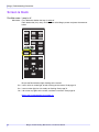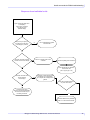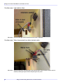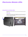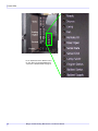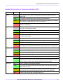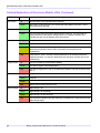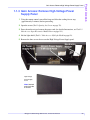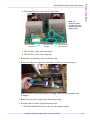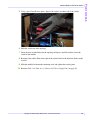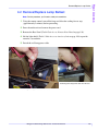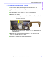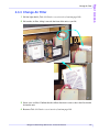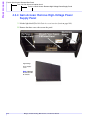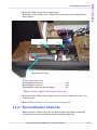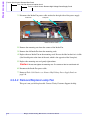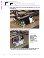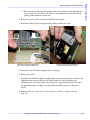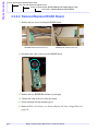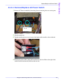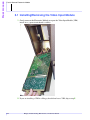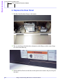
1
Margay
Troubleshooting,
Maintenance,
and Service
Manual
Copyright ©2006 by Clarity Visual Systems™, Inc. All Rights Reserved.
Contents of this publication may not be reproduced in any form without permission of Clarity Visual Systems, Inc.
Trademark Credits Windows™ is a trademark of Microsoft Corp.
Clarity's Big Picture™ is a trademark of Clarity Visual Systems, Inc.
APLCD® is a registered trademark Clarity Visual Systems, Inc.
All other names are trademarks or registered trademarks of their respective companies.
Disclaimer The information contained in this document is subject to change without notice. Clarity Visual Systems
(hereinafter, “the Company”) makes no warranty of any kind with regard to this material. While every precaution has been taken
in the preparation of this manual, the Company shall not be liable for errors or omissions contained herein or for incidental or
consequential damages in connection with the furnishing, performance, or use of this material.
Limited Warranty The Company warrants to Buyer that the WN-5040-720 (hereinafter, the “Product”), if properly used and
serviced, will perform substantially in accordance with the product data sheet and users manual, and will be free from defects in
material and workmanship for one year following date of shipment. This warranty does not apply to air filters and other
consumable parts.
If any Product fails to conform to the written warranty, the Company's exclusive liability and Buyer's exclusive remedy will be,
at Clarity's option, to repair, replace or credit Buyer's account with an amount equal to the price paid for any such defective
Product returned by Buyer during the warranty period, provided that: (a) Buyer promptly notifies the Company in writing that
such Product failed to conform, furnishes an explanation of any alleged deficiency and obtains from the Company a return
authorization; and (b) the Company is satisfied that claimed deficiencies actually exist and were not caused by accident, misuse,
neglect, alteration, improper installation or repair, or improper testing. the Company will have a reasonable time to make repairs,
to replace Products, or to credit Buyer's account.
Limitations Any written warranty offered by the Company is in lieu of all other warranties, express or implied. The Company
neither assumes nor authorizes any other person to assume any other liabilities in connection with the sales or use of any product
without limitation. The Company disclaims all other warranties, express or implied, including any warranty of merchantability
or fitness for a particular purpose. In no event will the Company be liable to buyer or any other party for procurement costs, loss
of profits, loss of use, or for any other incidental, consequential, indirect or special damages or for contribution or indemnity
claims, however caused. the Company's liability shall be limited to actual direct damages not in excess of the amounts paid to
the Company by buyer for the product. These limitations will apply to all claims, including, without limitation, warranty,
contract, indemnity, tort (including negligence), strict liability or otherwise.
Part Number: 072-0002-00
Rev 1.0.0, April 04, 2006
2
Margay Troubleshooting, Maintenance, and Service Manual
Contents
Preface
Audience . . . . . . . . . . . . . . . . . . . . . . . . . . . . . . . . . . . . . . . . . . . . . . . . . . . . . . . . . . . . . . . . . . . . . . . . . .7
How this Manual is Organized . . . . . . . . . . . . . . . . . . . . . . . . . . . . . . . . . . . . . . . . . . . . . . . . . . . . . . . . .7
Diagnosing Problems . . . . . . . . . . . . . . . . . . . . . . . . . . . . . . . . . . . . . . . . . . . . . . . . . . . . . . . . . . . . .7
Service and Maintenance Procedures . . . . . . . . . . . . . . . . . . . . . . . . . . . . . . . . . . . . . . . . . . . . . . . . .8
Troubleshooting Margay
General Troubleshooting Concepts and Procedures . . . . . . . . . . . . . . . . . . . . . . . . . . . . . . . . . . . . . . . . .9
Swapping Lamps and Ballasts . . . . . . . . . . . . . . . . . . . . . . . . . . . . . . . . . . . . . . . . . . . . . . . . . . . . .10
Swapping other parts . . . . . . . . . . . . . . . . . . . . . . . . . . . . . . . . . . . . . . . . . . . . . . . . . . . . . . . . . . . .11
Why not use a new part out of the box? . . . . . . . . . . . . . . . . . . . . . . . . . . . . . . . . . . . . . . . . . . . . . .11
EDID Issues . . . . . . . . . . . . . . . . . . . . . . . . . . . . . . . . . . . . . . . . . . . . . . . . . . . . . . . . . . . . . . . . . . .12
Margay Troubleshooting Procedures . . . . . . . . . . . . . . . . . . . . . . . . . . . . . . . . . . . . . . . . . . . . . . . . . . .13
Screen is black . . . . . . . . . . . . . . . . . . . . . . . . . . . . . . . . . . . . . . . . . . . . . . . . . . . . . . . . . . . . . . . . .14
Red or amber lights flashing on the screen. . . . . . . . . . . . . . . . . . . . . . . . . . . . . . . . . . . . . . . . . . . .15
Screen is black . . . . . . . . . . . . . . . . . . . . . . . . . . . . . . . . . . . . . . . . . . . . . . . . . . . . . . . . . . . . . . . . .16
Screen is black . . . . . . . . . . . . . . . . . . . . . . . . . . . . . . . . . . . . . . . . . . . . . . . . . . . . . . . . . . . . . . . . .17
Screen is black . . . . . . . . . . . . . . . . . . . . . . . . . . . . . . . . . . . . . . . . . . . . . . . . . . . . . . . . . . . . . . . . .18
Screen is black . . . . . . . . . . . . . . . . . . . . . . . . . . . . . . . . . . . . . . . . . . . . . . . . . . . . . . . . . . . . . . . . .19
Screen is solid color, but not black . . . . . . . . . . . . . . . . . . . . . . . . . . . . . . . . . . . . . . . . . . . . . . . . . .20
Lamp lights, but will not stay lit . . . . . . . . . . . . . . . . . . . . . . . . . . . . . . . . . . . . . . . . . . . . . . . . . . . .22
Picture is visible, but ….. . . . . . . . . . . . . . . . . . . . . . . . . . . . . . . . . . . . . . . . . . . . . . . . . . . . . . . . . .23
Picture is flipped . . . . . . . . . . . . . . . . . . . . . . . . . . . . . . . . . . . . . . . . . . . . . . . . . . . . . . . . . . . . . . . .24
Picture has a black edge . . . . . . . . . . . . . . . . . . . . . . . . . . . . . . . . . . . . . . . . . . . . . . . . . . . . . . . . . .25
Picture has black edge. . . . . . . . . . . . . . . . . . . . . . . . . . . . . . . . . . . . . . . . . . . . . . . . . . . . . . . . . . . .26
Picture has black edge. . . . . . . . . . . . . . . . . . . . . . . . . . . . . . . . . . . . . . . . . . . . . . . . . . . . . . . . . . . .27
Picture has a colored edge . . . . . . . . . . . . . . . . . . . . . . . . . . . . . . . . . . . . . . . . . . . . . . . . . . . . . . . .28
Picture is too large or too small . . . . . . . . . . . . . . . . . . . . . . . . . . . . . . . . . . . . . . . . . . . . . . . . . . . .29
Picture is noisy . . . . . . . . . . . . . . . . . . . . . . . . . . . . . . . . . . . . . . . . . . . . . . . . . . . . . . . . . . . . . . . . .30
Analog data (Analog 1 or Analog 2) picture has horizontal streaks or noise . . . . . . . . . . . . . . . . . .31
Analog data (Analog 1 or Analog 2) picture has vertical streaks . . . . . . . . . . . . . . . . . . . . . . . . . . .32
Analog data (Analog 1 or Analog 2) picture colors are wrong. . . . . . . . . . . . . . . . . . . . . . . . . . . . .33
RS232 or RS485 communication doesn’t work . . . . . . . . . . . . . . . . . . . . . . . . . . . . . . . . . . . . . . . .38
Useful commands for RS232 troubleshooting . . . . . . . . . . . . . . . . . . . . . . . . . . . . . . . . . . . . . . . . .39
RS232 diagnostic troubleshooting . . . . . . . . . . . . . . . . . . . . . . . . . . . . . . . . . . . . . . . . . . . . . . . . . .44
Margay doesn’t respond to remote control . . . . . . . . . . . . . . . . . . . . . . . . . . . . . . . . . . . . . . . . . . . .47
Margay doesn’t respond to remote control . . . . . . . . . . . . . . . . . . . . . . . . . . . . . . . . . . . . . . . . . . . .48
Margay doesn’t respond to remote control . . . . . . . . . . . . . . . . . . . . . . . . . . . . . . . . . . . . . . . . . . . .51
Opening rear panel does not shut off the lamp . . . . . . . . . . . . . . . . . . . . . . . . . . . . . . . . . . . . . . . . .52
Screens do not fit together well . . . . . . . . . . . . . . . . . . . . . . . . . . . . . . . . . . . . . . . . . . . . . . . . . . . .53
Dirt or smudges in the picture. . . . . . . . . . . . . . . . . . . . . . . . . . . . . . . . . . . . . . . . . . . . . . . . . . . . . .54
Margay Troubleshooting, Maintenance, and Service Manual
3
Contents
On-Screen Codes
Working with On-Screen Codes . . . . . . . . . . . . . . . . . . . . . . . . . . . . . . . . . . . . . . . . . . . . . . . . . . . . . . 55
Manually turning on the On-Screen code . . . . . . . . . . . . . . . . . . . . . . . . . . . . . . . . . . . . . . . . . . . . 55
Automatic On-Screen code display . . . . . . . . . . . . . . . . . . . . . . . . . . . . . . . . . . . . . . . . . . . . . . . . . 56
Reading On-Screen codes . . . . . . . . . . . . . . . . . . . . . . . . . . . . . . . . . . . . . . . . . . . . . . . . . . . . . . . . . . . 57
Margay On-screen Code Details and Actions to Take . . . . . . . . . . . . . . . . . . . . . . . . . . . . . . . . . . . . . 58
Red Red Red . . . . . . . . . . . . . . . . . . . . . . . . . . . . . . . . . . . . . . . . . . . . . . . . . . . . . . . . . . . . . . . . . . 59
Red Amber . . . . . . . . . . . . . . . . . . . . . . . . . . . . . . . . . . . . . . . . . . . . . . . . . . . . . . . . . . . . . . . . . . . 62
Red Amber Red . . . . . . . . . . . . . . . . . . . . . . . . . . . . . . . . . . . . . . . . . . . . . . . . . . . . . . . . . . . . . . . 63
Red Red Amber . . . . . . . . . . . . . . . . . . . . . . . . . . . . . . . . . . . . . . . . . . . . . . . . . . . . . . . . . . . . . . . 64
Red Red Amber Red . . . . . . . . . . . . . . . . . . . . . . . . . . . . . . . . . . . . . . . . . . . . . . . . . . . . . . . . . . . . 65
Red Red . . . . . . . . . . . . . . . . . . . . . . . . . . . . . . . . . . . . . . . . . . . . . . . . . . . . . . . . . . . . . . . . . . . . . . 66
Red Red Amber Amber . . . . . . . . . . . . . . . . . . . . . . . . . . . . . . . . . . . . . . . . . . . . . . . . . . . . . . . . . 67
Red Red Red Red. . . . . . . . . . . . . . . . . . . . . . . . . . . . . . . . . . . . . . . . . . . . . . . . . . . . . . . . . . . . . . . 68
Amber Amber Red. . . . . . . . . . . . . . . . . . . . . . . . . . . . . . . . . . . . . . . . . . . . . . . . . . . . . . . . . . . . . . 69
Amber Amber . . . . . . . . . . . . . . . . . . . . . . . . . . . . . . . . . . . . . . . . . . . . . . . . . . . . . . . . . . . . . . . . . 70
Amber Amber Amber . . . . . . . . . . . . . . . . . . . . . . . . . . . . . . . . . . . . . . . . . . . . . . . . . . . . . . . . . . . 71
Solid Amber . . . . . . . . . . . . . . . . . . . . . . . . . . . . . . . . . . . . . . . . . . . . . . . . . . . . . . . . . . . . . . . . . . . 72
Electronics Module LEDs
Using Electronics Module LEDs . . . . . . . . . . . . . . . . . . . . . . . . . . . . . . . . . . . . . . . . . . . . . . . . . . . . . . 73
To see LEDs. . . . . . . . . . . . . . . . . . . . . . . . . . . . . . . . . . . . . . . . . . . . . . . . . . . . . . . . . . . . . . . . . . . 73
Detailed Explanation of Electronics Module LEDs . . . . . . . . . . . . . . . . . . . . . . . . . . . . . . . . . . . . 75
Front-Access Maintenance and Service Procedures
Introduction . . . . . . . . . . . . . . . . . . . . . . . . . . . . . . . . . . . . . . . . . . . . . . . . . . . . . . . . . . . . . . . . . . . . . . 77
Required Tools. . . . . . . . . . . . . . . . . . . . . . . . . . . . . . . . . . . . . . . . . . . . . . . . . . . . . . . . . . . . . . . . . 77
Task 1: Opening the Screen . . . . . . . . . . . . . . . . . . . . . . . . . . . . . . . . . . . . . . . . . . . . . . . . . . . . . . . . . . 78
Task 1.1: Gain Access: Lift Light Shield . . . . . . . . . . . . . . . . . . . . . . . . . . . . . . . . . . . . . . . . . . . . 82
Task 1.1.1: Change Air Filter . . . . . . . . . . . . . . . . . . . . . . . . . . . . . . . . . . . . . . . . . . . . . . . . . . 83
Task 1.1.2: Remove/Replace Lamp Ballast. . . . . . . . . . . . . . . . . . . . . . . . . . . . . . . . . . . . . . . . 84
Task 1.1.3: Gain Access: Remove High-Voltage Power Supply Panel. . . . . . . . . . . . . . . . . . . 89
Task 1.1.3.1: Remove/Replace Intake Fan . . . . . . . . . . . . . . . . . . . . . . . . . . . . . . . . . . . . . 91
Task 1.1.3.2: Remove/Replace Lamp Fan . . . . . . . . . . . . . . . . . . . . . . . . . . . . . . . . . . . . . . 91
Task 1.1.3.3: Remove/Replace AC Fuse . . . . . . . . . . . . . . . . . . . . . . . . . . . . . . . . . . . . . . . 92
Task 1.1.3.4: Remove/Replace High-Voltage Power Supply . . . . . . . . . . . . . . . . . . . . . . . 92
Task 1.1.4: Gain Access: Remove DC Power Supply Panel . . . . . . . . . . . . . . . . . . . . . . . . . . . 95
Task 1.1.4.1: Remove/Replace DC Power Supply . . . . . . . . . . . . . . . . . . . . . . . . . . . . . . . 97
Task 1.1.4.2: Remove/Replace IR/LED Board . . . . . . . . . . . . . . . . . . . . . . . . . . . . . . . . . . 99
4
Margay Troubleshooting, Maintenance, and Service Manual
Contents
Task 1.1.4.3: Remove/Replace AC Power Switch . . . . . . . . . . . . . . . . . . . . . . . . . . . . . . .100
Task 1.1.5: Remove/Replace Lamp . . . . . . . . . . . . . . . . . . . . . . . . . . . . . . . . . . . . . . . . . . . . .102
Task 1.1.6: Remove/Replace Optical Engine . . . . . . . . . . . . . . . . . . . . . . . . . . . . . . . . . . . . . .107
Task 1.2: Gain Access: Open Electronics Module Door . . . . . . . . . . . . . . . . . . . . . . . . . . . . . . . .111
Task 1.2.1: Servicing the Electronics Module . . . . . . . . . . . . . . . . . . . . . . . . . . . . . . . . . . . . .112
Task 1.2.1.1: Remove Electronics Module. . . . . . . . . . . . . . . . . . . . . . . . . . . . . . . . . . . . .112
Task 1.2.1.1.1: Installing/Removing the Video Input Module . . . . . . . . . . . . . . . . . . .114
Task 1.2.1.2: Replace Electronics Module . . . . . . . . . . . . . . . . . . . . . . . . . . . . . . . . . . . . .117
Task 1.3: Remove/Replace Large Mirror . . . . . . . . . . . . . . . . . . . . . . . . . . . . . . . . . . . . . . . . . . . .119
Remove the old mirror . . . . . . . . . . . . . . . . . . . . . . . . . . . . . . . . . . . . . . . . . . . . . . . . . . . . . . . . . .119
Prepare the new mirror for installation . . . . . . . . . . . . . . . . . . . . . . . . . . . . . . . . . . . . . . . . . . . . . .120
Align the image. . . . . . . . . . . . . . . . . . . . . . . . . . . . . . . . . . . . . . . . . . . . . . . . . . . . . . . . . . . . . . . .121
Task 1.4: Adjusting the Large Mirror for Keystoned Images. . . . . . . . . . . . . . . . . . . . . . . . . . . . .122
Task 1.5: Removing and Replacing the Small Mirror . . . . . . . . . . . . . . . . . . . . . . . . . . . . . . . . . .124
Task 2: Replacing Screens . . . . . . . . . . . . . . . . . . . . . . . . . . . . . . . . . . . . . . . . . . . . . . . . . . . . . . . . . .125
Task 3: Cleaning Mirrors, Lenses, and Screens . . . . . . . . . . . . . . . . . . . . . . . . . . . . . . . . . . . . . . . . . .127
Cleaning products and how to use them . . . . . . . . . . . . . . . . . . . . . . . . . . . . . . . . . . . . . . . . . . . . .127
Cloth to use . . . . . . . . . . . . . . . . . . . . . . . . . . . . . . . . . . . . . . . . . . . . . . . . . . . . . . . . . . . . . . . . . . .127
Removing dry dust . . . . . . . . . . . . . . . . . . . . . . . . . . . . . . . . . . . . . . . . . . . . . . . . . . . . . . . . . . . . .128
Cleaning lenses . . . . . . . . . . . . . . . . . . . . . . . . . . . . . . . . . . . . . . . . . . . . . . . . . . . . . . . . . . . . . . . .128
Where is the dirt? . . . . . . . . . . . . . . . . . . . . . . . . . . . . . . . . . . . . . . . . . . . . . . . . . . . . . . . . . . . . . .128
Rear-Access Maintenance and Service Procedures
Introduction. . . . . . . . . . . . . . . . . . . . . . . . . . . . . . . . . . . . . . . . . . . . . . . . . . . . . . . . . . . . . . . . . . . . . .129
Required Tools . . . . . . . . . . . . . . . . . . . . . . . . . . . . . . . . . . . . . . . . . . . . . . . . . . . . . . . . . . . . . . . .129
Task 4: Gain Access: Remove Rear Panel . . . . . . . . . . . . . . . . . . . . . . . . . . . . . . . . . . . . . . . . . . . . . .130
Task 4.1: Remove/Replace Lamp . . . . . . . . . . . . . . . . . . . . . . . . . . . . . . . . . . . . . . . . . . . . . . . . . .131
Resetting Lamp Hours . . . . . . . . . . . . . . . . . . . . . . . . . . . . . . . . . . . . . . . . . . . . . . . . . . . . . . . . . .133
Final Steps After Replacing Lamps . . . . . . . . . . . . . . . . . . . . . . . . . . . . . . . . . . . . . . . . . . . . . . . .134
Task 4.2: Remove/Replace Lamp Ballast. . . . . . . . . . . . . . . . . . . . . . . . . . . . . . . . . . . . . . . . . . . .135
Task 4.3: Gain Access to interior of unit . . . . . . . . . . . . . . . . . . . . . . . . . . . . . . . . . . . . . . . . . . . .140
Task 4.3.1: Adjusting the Optical Engine On Its Carrier . . . . . . . . . . . . . . . . . . . . . . . . . . . . .141
Task 4.3.2: Removing the Optical Engine . . . . . . . . . . . . . . . . . . . . . . . . . . . . . . . . . . . . . . . .143
Task 4.3.2.1: Replacing the Optical Engine . . . . . . . . . . . . . . . . . . . . . . . . . . . . . . . . . . . .145
Task 4.3.3: Change Air Filter . . . . . . . . . . . . . . . . . . . . . . . . . . . . . . . . . . . . . . . . . . . . . . . . . .147
Margay Troubleshooting, Maintenance, and Service Manual
5
Contents
Task 4.3.4: Gain Access: Remove High-Voltage Power Supply Panel. . . . . . . . . . . . . . . . . . 148
Task 4.3.4.1: Remove/Replace Intake Fan . . . . . . . . . . . . . . . . . . . . . . . . . . . . . . . . . . . . 149
Task 4.3.4.2: Remove/Replace Lamp Fan . . . . . . . . . . . . . . . . . . . . . . . . . . . . . . . . . . . . . 150
Task 4.3.4.3: Remove/Replace AC Fuse . . . . . . . . . . . . . . . . . . . . . . . . . . . . . . . . . . . . . . 151
Task 4.3.4.4: Remove/Replace High-Voltage Power Supply . . . . . . . . . . . . . . . . . . . . . . 151
Task 4.3.5: Gain Access: Remove/Replace DC Power Supply Panel . . . . . . . . . . . . . . . . . . . 154
Task 4.3.5.1: Remove/Replace DC Power Supply . . . . . . . . . . . . . . . . . . . . . . . . . . . . . . 155
Task 4.3.5.2: Remove/Replace IR/LED Board . . . . . . . . . . . . . . . . . . . . . . . . . . . . . . . . . 158
Task 4.3.5.3: Remove/Replace AC Power Switch . . . . . . . . . . . . . . . . . . . . . . . . . . . . . . 159
Task 5: Remove Electronics Module. . . . . . . . . . . . . . . . . . . . . . . . . . . . . . . . . . . . . . . . . . . . . . . . . . 161
Task 5.1: Installing/Removing the Video Input Module . . . . . . . . . . . . . . . . . . . . . . . . . . . . . . . . 164
Task 5.2: Replace Electronics Module . . . . . . . . . . . . . . . . . . . . . . . . . . . . . . . . . . . . . . . . . . . . . 167
Task 6: Replace the Rear Panel . . . . . . . . . . . . . . . . . . . . . . . . . . . . . . . . . . . . . . . . . . . . . . . . . . . . . . 168
Additional Resources
Accessing Clarity’s Customer Support Website . . . . . . . . . . . . . . . . . . . . . . . . . . . . . . . . . . . . . . . . . 171
Downloading Additional Documentation and Firmware. . . . . . . . . . . . . . . . . . . . . . . . . . . . . . . . . . . 171
Downloading Utility Software. . . . . . . . . . . . . . . . . . . . . . . . . . . . . . . . . . . . . . . . . . . . . . . . . . . . . . . 171
Contact Clarity Customer Support. . . . . . . . . . . . . . . . . . . . . . . . . . . . . . . . . . . . . . . . . . . . . . . . . . . . 173
Index 175
6
Margay Troubleshooting, Maintenance, and Service Manual
Preface
The Margay is a 50" (diagonal screen measurement) DLP™ video display unit. Margays
may be installed in many different configurations (stand-alone, banner, tower, or wall)
and can be mounted upright, flying or tilted.
The most common configuration is a wall of several units high by many units wide to
create a large video screen.
Audience
This manual is intended for factory trained and certified QST (Quality Service
Technician) personnel only.
WARNING!
The procedures described in this manual could expose personnel to UV light,
hot surfaces, and potentially lethal high voltage. You must observe all safety notices while
working on the display.
How this Manual is Organized
This manual may be used online or printed on paper. For example, many hyperlinks
appear with blue underlining and when clicked onscreen, display the linked section.
There are five sections in this manual.
The first three sections contain methods of diagnosing problems. The last two sections
contain service and maintenance procedures, which are presented hierarchically.
Diagnosing Problems
There are three separate sections to help you diagnose problems with the display.
Troubleshooting
The Troubleshooting section contains lists of symptoms (such as “The screen is black.”)
that are linked to a series of detailed questions that lead you to a solution. This is a good
place to start. See Margay Troubleshooting Procedures on page 13.
On-screen Codes
The On-Screen codes are red and amber lights that flash in specific patterns on the
screen. The pattern of flashing lights can tell you what is wrong with the display. These
flashing lights are particularly helpful when the lamp won’t light. The On-screen Code
section lists the codes in a visual form. You can click on any of them and go to the
explanation of it. See On-Screen Codes on page 55.
Electronics Module LEDs
The LEDs section explains the meaning of each of the LEDs found on the electronics
module. See Electronics Module LEDs on page 73.
Margay Troubleshooting, Maintenance, and Service Manual
7
Service and Maintenance Procedures
Service and Maintenance Procedures
The maintenance and service procedures are divided into two sections: front service
access and rear service access. If your installation permits only front access, the rear
access procedures are not relevant for you.
Initially, it may seem odd to group service and maintenance procedures together, but
many service procedures share initial steps with maintenance procedures.
Service Task Hierarchy
All the service tasks in this manual are hierarchical. For example, to install or remove
the Video Input Module (Task 1.2.1.1.1 Installing/Removing the Video Input Module),
you must first perform the “parent” tasks that contain it, namely:
Task 1 Opening the Screen, Task 1.2 Gain Access: Open Electronics Module Door, Task
1.2.1 Servicing the Electronics Module, and Task 1.2.1.1 Remove Electronics Module.
After performing these “parent” tasks, you may then install or remove the VIM.
See Front-Access Maintenance and Service Procedures on page 77.
Note: These procedures require a Clarity remote control. You may also use RS232 commands
to perform these procedures, provided you know the RS232-command equivalents.
8
Margay Troubleshooting, Maintenance, and Service Manual
Troubleshooting Margay
General Troubleshooting Concepts and Procedures
All troubleshooting procedures require you to gather information, make assumptions,
and then test those assumptions until you arrive at the problem and can solve it.
Possible solutions to the most common problems are explained below. For more
involved problems and solutions, see Margay Troubleshooting Procedures on page 13.
If your screen is black
Do This
Step 1. On the remote, press
Result
A menu appears
MONITOR
Explanation / Further Action
The source is black. On the remote
press SOURCE to change to different
source
If you know the source is not black,
go to Step 2.
No menu appears, but I see
flashing lights
The lamp may not be lit. On the
remote, press ON.
If the screen is still black, For help
interpreting the flashing on-screen
lights, see On-Screen Codes on
page 55.
Step 2. On the remote, press
CURTAIN.
No menu appears and no flashing
lights
Go to Step 4.
The correct source appears
The Curtain (aka Video Mute) was
on.
If the correct source did not appear,
go to Step 3.
Step 3. On the remote, press
twice.
The Test Patterns menu appears
Check that no test patterns are
selected. If a test pattern is
selected, move the selector to None
and press ENTER.
Step 4. Check Power cable is
connected and power rocker switch
is ON
Reconnect cable or turn on unit
If none of these steps have
resolved the problem, see Margay
Troubleshooting Procedures on
page 13
MONITOR
9
Swapping Lamps and Ballasts
If your screen is a solid color, but not black
Do This
Result
Explanation / Further Action
Step 1. On the remote, press
CURTAIN.
The correct source
appears
If the correct source did not appear, go to Step 2.
Step 2. On the remote, press
twice.
The Test Patterns
menu appears
Check that no test patterns are selected. If a test
pattern is selected, move the selector to None and
press ENTER.
MONITOR
If no test pattern was selected, go to Step 3.
Step 3. Check to see if the
source is a solid color.
If the source is not a solid color and none of these steps have resolved the
problem, see Margay Troubleshooting Procedures on page 13
Margay doesn’t respond to remote control
Possible Cause
Possible Resolution
IR response disabled via RS232
Re-enable IR response using RS232 commands
Remote batteries are dead or improperly installed
Replace or reinstall batteries
Lamps won’t light
Possible Cause
Possible Resolution
Rear panel is open or
light shield is up
Put the rear panel or light shield back in place and cycle the AC power off, then on
A fan has failed
Look at the LEDs on the Electronics Module for a red LED in the Fan section. All fans
must operate for the lamps to light. See Electronics Module LEDs on page 73.
If the Door Open LED is amber, cycle the AC power off, then on
To test a lamp, remove it and exchange it for a lamp you know is good from another Margay. See Swapping
Lamps and Ballasts on page 10.
If the “good” lamp does not work in the “bad” location, or the “bad” lamp works in another location, the problem
may be a failed lamp ballast.
Swapping Lamps and Ballasts
Some lamp and ballast problems defy diagnostics and require you to actually try other
parts to determine the cause of failure.
10
Margay Troubleshooting, Maintenance, and Service Manual
Swapping other parts
WARNING!
Always turn off the AC power and remove the power cord before working
inside the display and before removing a lamp.
• If you have AC and ballast or 350V power, try swapping the lamp into a display
where the lamp is good.
Display A
Display B
Lamp A doesn’t
work here.
Move Lamp A
here.
Move good Lamp B
out temporarily.
- If Lamp A works in Display B, put it back in Display A. Lamp A is OK.
- If Lamp A does not work in Display B, the problem is Lamp A. Put a new lamp
in Display A.
• If the lamp is OK, try swapping the ballast in the same way. The lamp ballast
provides power to the lamp. It is an electronic part, and all electronic parts are
subject to eventual failure.
• Fan failed. All fans are sensed, which means the Electronics Module knows whether
they are running or not. If they don’t run when they should, the Electronics Module
turns off the lamp and prevents it from striking (turning on) again.
Swapping other parts
Exchanging parts from one display to another is an effective way to find a problem. If
the problem follows the part to the new unit, that part was at fault.
If the problem stays in the first unit, you haven’t found the problem yet, but you have
learned something: the part you moved was not the problem. Put it back in the original
unit and try something else.
You can swap Electronics Modules or fans in the same way to see if one is bad.
When you swap Electronics Modules for testing, remember to put them back in their
original locations. Otherwise you may have to do setup procedures again, such as Input
Level adjustment and Color Balance, because these values are stored in the Electronics
Module.
When you swap fans, always exchange fans of the same size.
Why not use a new part out of the box?
It may seem like a good idea to take a new part out of the box and substitute it for a
suspected part in the display. However, there is a slight chance that the part in the box
doesn’t work.
If you test a part by putting in a known good part, you get better information.
Margay Troubleshooting, Maintenance, and Service Manual
11
EDID Issues
EDID Issues
One problem with EDID is that Clarity displays are capable of many more resolutions
(video timings) than can be stored in a data block of only 128 bytes. Clarity displays are
capable of hundreds of resolutions, but the EDID block has room to store only dozens.
This means that some video cards will not put out certain resolutions, even though the
connected Clarity display is capable of handling them. If the resolution you want to use
is not listed in the Clarity EDID, and the video card won’t list that resolution unless it is
seen in the EDID, what can you do?
A possible solution is to uncheck the Plug and Play box in the Miscellaneous menu
(Main Menu > Advanced Options > Miscellaneous Options).
M is cel la ne o us
B ee p er
C u rtai n Pattern
L og o
A u to Co d es
P lu g an d P l ay ( E D ID E n ab le )
I n ver te d In sta ll at io n
P r ef err ed S o u r c e D et ec t io n
H D In t erl ac ed C on t en t Mo t io n
16 x 9
No rm a l
After you have unchecked Plug and Play (EDID Enabled), reboot the source
computer.
Note: If you use a long-line distribution system, EDID may not function correctly or at all.
12
Margay Troubleshooting, Maintenance, and Service Manual
Margay Troubleshooting Procedures
Margay Troubleshooting Procedures
Click on the symptom of the problem or turn to the
corresponding page number.
1 The screen is black. Go to page 14.
2 The screen is a solid color, but not black. Go to page 20.
3 The lamp will light, but it won’t stay on. Go to page 22.
4 The picture is visible, but there is something wrong with it. Go to page 23.
5 RS232 or RS485 communication doesn’t work. Go to page 38.
6 The Margay doesn’t respond to the remote control. Go to page 47.
7 Opening the rear panel does not shut off the lamp. Go to page 52.
8 Opening the light shield does not shut off the lamp. Go to page 52.
9 The screens don’t fit together well. Go to page 53.
10 There is dirt or smudges in the picture. Go to page 54.
Margay Troubleshooting, Maintenance, and Service Manual
13
Margay Troubleshooting Procedures
Screen is black
Possible cause: Lamp is off
What to do: First, determine whether the lamp is really off.
From about 6 feet (2 m) away, aim the remote at the Margay screen and press the MONITOR
button
ON
SOURCE
LEVEL
CURTAIN
FREQ/
PHASE
SAVE
SETUP
LAMP
OFF
®
SIZE/POS
MONITOR
WALL
MISC
MENU
PREV
ENTER
-
+
.
Do you see Red or Amber lights flashing on the screen?
Yes I see a red or an amber light, or both, flashing on the screen. Go to page 15.
Yes I see an amber light, but it is steady, not flashing. Go to page 72.
No I do not see any lights on the screen, and there is no menu. Go to page 16.
Back to the Troubleshooting List on page 13.
14
Margay Troubleshooting, Maintenance, and Service Manual
Margay Troubleshooting Procedures
Red or amber lights flashing on the screen
Possible cause: You don’t know the cause yet. Keep reading.
What to do: Notice the pattern of the lights—red, red, amber or whatever it is.
Go to “Margay On-screen Code Details and Actions to Take” on page 58 to help you decode the
message.
Back to the previous question
Back to the Troubleshooting List on page 13.
Margay Troubleshooting, Maintenance, and Service Manual
15
Margay Troubleshooting Procedures
Screen is black
and no red or amber lights are flashing on the screen
Possible cause: Power failure
What to do: Open the screen (Task 1 Opening the Screen on page 78) and the electronics module door
(Task 1.2 Gain Access: Open Electronics Module Door on page 111). Or look at the Electronics
Module from the rear.
Are any of the LEDs on the Electronics Module lit?
Yes some of the LEDs are either red or green. Go to page 17.
No none of the LEDs are lit. They are all off.Go to page 18.
Back to the previous question
Back to the Troubleshooting List on page 13.
16
Margay Troubleshooting, Maintenance, and Service Manual
Margay Troubleshooting Procedures
Screen is black
and no red or amber lights are flashing on the screen
and some LEDs are lit on the Electronics Module.
Discussion: If some of the LEDs are lit on the Electronics Module, it usually means that the module is working. At least it has power.
The On-Screen Codes (red or amber lights on the screen) should be working also. But you got
to this point because the On-Screen Codes weren’t flashing.
Possible cause: On-Screen Code board covered, failed, or disconnected.
What to do: This board is under the DC Power Supply & IR board cover. To inspect it, check cable connections, or replace it, see Task 1.1.4 Gain Access: Remove DC Power Supply Panel on page 95
and Task 1.1.4.2 Remove/Replace IR/LED Board on page 99. If you have rear access, see Task
4.3.5 Gain Access: Remove/Replace DC Power Supply Panel on page 154 and Task 4.3.5.2
Remove/Replace IR/LED Board on page 158.
Possible cause: The light shield is raised.
What to do: When the light shield is raised, it can block the flashing On-Screen Code lights. However, when it
is raised, the lamp will not light, because the interlock switch is open. To lower the light shield,
see Task 1.1 Gain Access: Lift Light Shield on page 82 or Task 4.3 Gain Access to interior of unit
on page 140.
Back to the previous question
Back to the Troubleshooting List on page 13.
Margay Troubleshooting, Maintenance, and Service Manual
17
Margay Troubleshooting Procedures
Screen is black
and no red or amber lights are flashing on the screen
and no LEDs on the Electronics Module are lit.
Possible cause: AC power is missing
What to do: Check the main power switch just below the Electronics Module. Is it lit?
No Then there is no AC power to the Margay.
Turn on the AC switch.
If the switch did not light, check the power cord.
Check the AC outlet where the power cord is plugged in.
Check the fuse on the display: see Task 1 Opening the Screen on page 78, Task 1.1 Gain
Access: Lift Light Shield on page 82, Task 1.1.3 Gain Access: Remove High-Voltage Power
Supply Panel on page 89, and Task 1.1.3.3 Remove/Replace AC Fuse on page 92.
If you have rear access, see Task 4 Gain Access: Remove Rear Panel on page 130, Task 4.3
Gain Access to interior of unit on page 140, Task 4.3.4 Gain Access: Remove High-Voltage
Power Supply Panel on page 148, and Task 4.3.4.3 Remove/Replace AC Fuse on page 151.
If the Input AC fuse (F1 on the High-Voltage Power Supply) fails, no power goes into the unit;
you may need to replace the High-Voltage Power Supply itself.
If the Output AC fuse (F2 on the High-Voltage Power Supply) fails, the Electronics Module will
still receive power, but the lamps won’t light because no power is going to the ballast. Also if the
Output fuse blows, the problem might be the ballast and you may need to replace the ballast.
Test this by swapping a good ballast.
Check the AC power switch on the display with a voltmeter.
If the switch needs to be replaced, see Task 1 Opening the Screen on page 78, Task 1.2 Gain
Access: Open Electronics Module Door on page 111, Task 1.1.4 Gain Access: Remove DC
Power Supply Panel on page 95, and Task 1.1.4.3 Remove/Replace AC Power Switch on
page 100.
If you have rear access, see Task 4 Gain Access: Remove Rear Panel on page 130, Task 4.3
Gain Access to interior of unit on page 140, Task 4.3.5 Gain Access: Remove/Replace DC
Power Supply Panel on page 154, and Task 4.3.5.3 Remove/Replace AC Power Switch on
page 159.
You can’t solve any other problems until the AC switch is lit.
Yes Then the Margay has AC power.
Back to the previous question
Back to the Troubleshooting List on page 13.
18
Margay Troubleshooting, Maintenance, and Service Manual
Margay Troubleshooting Procedures
Screen is black
and no red or amber lights are flashing on the screen
and no LEDs on the Electronics Module are lit
and AC power switch is lit.
Possible cause: Low-voltage power supply failed or not connected
What to do: Check that all the connectors on the low-voltage power supply are secure.
Swap this LV power supply with a known good one from another Margay.
To remove and replace the DC Power Supply from the front of the display, see Task 1.1.4 Gain
Access: Remove DC Power Supply Panel on page 95, Task 1.1.4.1 Remove/Replace DC Power
Supply on page 97.
If you have rear access, see Task 4.3.5 Gain Access: Remove/Replace DC Power Supply Panel
on page 154, and Task 4.3.5.1 Remove/Replace DC Power Supply on page 155.
Possible cause: Electronics module not connected to the LV power supply.
What to do: Check connectors on the bottom of the Electronics Module.
For information about Electronics Module cable connections, see Task 1.2 Gain Access: Open
Electronics Module Door on page 111 and Task 1.2.1 Servicing the Electronics Module on
page 112. To inspect cable connections from the rear, see Task 5 Remove Electronics Module
on page 161.
Possible cause: Electronics module failed.
What to do: Swap this Electronics Module with a known good Electronics Module from another Margay. If
this Margay now works but the other one doesn’t, the problem was the Electronics Module.
Order a new one.
To remove and replace the Electronics Module from the front, see Task 1.2 Gain Access: Open
Electronics Module Door on page 111 and Task 1.2.1 Servicing the Electronics Module on
page 112.
To remove and replace the Electronics Module from the rear, see Task 5 Remove Electronics
Module on page 161.
Back to the previous question
Back to the Troubleshooting List on page 13.
Margay Troubleshooting, Maintenance, and Service Manual
19
Margay Troubleshooting Procedures
Screen is solid color, but not black
Discussion: You know the lamps are lit. The screen is a solid color for one of these reasons.
Possible cause: There is a test pattern active.
What to do: Open the Test Pattern menu. (MENU > DIAGNOSTICS > TEST PATTERNS) Select None and press
ENTER.
Tes t P at t er n s
No n e
Cu st o m C ol o r
White
Gray Sc ale
Grid
Re d
Re d Sca le
Al ig n me n t Da sh es
Green
Green Scale
4x 4 C h ec ker bo a rd
Bl u e
Bl ue Sc al e
Un if o rm it y
Bl ac k
Co lo rs
Fo c us
Gray
Co lo r Ba rs
Lo g o
Possible cause: No source, which means the Curtain (aka Video Mute) is on, and the Curtain is
set to the solid color you see.
What to do: Check the Picture menu. (With no menus showing, press MENU. Select Picture and press
ENTER.
)fs
Picture
Source
C o lo rspa ce
Sy nc Ty pe
Ve rti ca l F re q ue nc y (f ra m e l oc ke d )
An a lo g 1
RGB
U n kn o w n
60 Hz
H o r iz o n tal Fr eq u en cy
0. 00k Hz
Pi xe l F re q ue nc y
0. 00M Hz
H o r iz o n tal Re so lu t io n
0
Ve rti ca l R es o lu ti o n
0
F r e qu e nc y
0
P h a se
Sh a rp ne ss
0. 0°
S ha rp es t
I np u t L ev els
20
Margay Troubleshooting, Maintenance, and Service Manual
Margay Troubleshooting Procedures
If the Sync Type is Unknown, either there is no source picture, or the source picture is a type
that the Margay can’t display. Check the source.
Possible cause: Curtain has been turned on manually, and it is set to a solid color.
What to do: Press the CURTAIN button on the remote. If the color does not go away, press it again to turn
Curtain off.
Possible cause: The source itself is producing the solid color.
What to do: The problem is not in the Margay. Look at the source.
Picture
Source
An a lo g 1
C o lo rspa ce
S y n c Ty p e
RGB
Sepa ra te H&V
Ve rti ca l F re q ue nc y (f ra m e l oc ke d )
60 Hz
H o r iz o n tal Fr eq u en cy
5 0. 00k Hz
Pi xe l F re q ue nc y
8 0. 10M Hz
H o r iz o n tal Re so lu t io n
13 66
Ve rti ca l R es o lu ti o n
7 68
F r e qu e nc y
16 02
P h a se
2 2. 5°
Sh a rp ne ss
S ha rp es t
I np u t L ev els
Back to the Troubleshooting List on page 13.
Margay Troubleshooting, Maintenance, and Service Manual
21
Margay Troubleshooting Procedures
Lamp lights, but will not stay lit
Possible cause: The lamp can no longer maintain an arc between its electrodes.
What to do: Replace the lamp with a known good lamp, one from another Margay that works.
To service lamps from the front, see Task 1.1.5 Remove/Replace Lamp on page 102. To service
lamps from the rear, see Task 4.1 Remove/Replace Lamp on page 131.
Discussion: This is a relatively easy test to make.
Possible cause: If the lamp was good, check the ballast.
What to do: Replace the lamp ballast with a known good ballast, one from another Margay that works.
To service the ballast from the front, see Task 1.1.2 Remove/Replace Lamp Ballast on page 84.
To service the ballast from the rear, see Task 4.2 Remove/Replace Lamp Ballast on page 135.
Discussion: This is a little more difficult, but still relatively easy.
Back to the Troubleshooting List on page 13.
22
Margay Troubleshooting, Maintenance, and Service Manual
Margay Troubleshooting Procedures
Picture is visible, but ….
a … it is flipped. Go to page 24.
b … it has a black edge. Go to page 25.
c … it has a colored edge. Go to page 28.
d … it is too small. Go to page 29.
e … it is too large; the edges are cut off. Go to page 29.
f … it is noisy. Go to page 30.
g … it has horizontal streaks or noise. Go to page 31.
h … it has vertical streaks. Go to page 32.
i … the colors are wrong. Go to page 33.
Back to the Troubleshooting List on page 13.
Margay Troubleshooting, Maintenance, and Service Manual
23
Margay Troubleshooting Procedures
Picture is flipped
Possible cause: Image is flipped in Miscellaneous menu.
What to do: Check or uncheck the Inverted Installation box. It should by checked only if the Margay is
installed upside down.
MENU
> ADVANCED OPTIONS > MISCELLANEOUS
M is cel la ne o us
B ee p er
C u rtai n Pattern
L og o
A u to Co d es
P lu g an d P l ay ( E D ID E n ab le )
I n ver te d In sta ll at io n
P r ef err ed S o u r c e D et ec t io n
H D In t erl ac ed C on t en t Mo t io n
16 x 9
No rm a l
Back to the "Picture is visible" list
Back to the Troubleshooting List on page 13.
24
Margay Troubleshooting, Maintenance, and Service Manual
Margay Troubleshooting Procedures
Picture has a black edge
Possible cause: Picture is not positioned correctly.
What to do: Use the Position control. On the remote, press SIZE/POS
ON
SOURCE
LEVEL
CURTAIN
FREQ/
PHASE
SAVE
SETUP
LAMP
OFF
Pic t ur e P os it io n
U s e a r r o w k e y s t o m ov e i m a g e
Ho ri z on ta l P os it io n
®
Vert ic al Po si t io n
SIZE/POS
MONITOR
WALL
MISC
MENU
PREV
ENTER
16 8
19
Pic t ur e P os it io n
U s e a r r o w k e y s t o m ov e i m a g e
Ho ri z on ta l P os it io n
- 0-
Vert ic al Po si t io n
- 0-
Note: If both positions are at zero, the image is DVI and cannot be adjusted.
Using the Up and Down arrow keys, move the selector to Horizontal or Vertical Position. Use the
Left and Right arrows to move the image.
Did that move the black edge?
Yes Go to page 23.
No Go to page 26.
Back to the "Picture is visible" list on page 23
Back to the Troubleshooting List on page 13.
Margay Troubleshooting, Maintenance, and Service Manual
25
Margay Troubleshooting Procedures
Picture has black edge
and Position control does not help.
Possible cause: The optical engine is not aligned properly
Discussion: If you move the picture toward the black edge with the Picture Position menu, and the picture just
disappears into the black edge, this indicates that the optical engine is definitely not aligned
properly. The image from the optical engine is not aimed at the screen.
What to do: Open the Engine Alignment menu and move the engine. The User Guide has a complete
description of this process in the section called “Adjusting Margay’s Engine: Important Step.”
Mai n Me nu
A dv an ce d O p t io n s
P i c tu r e
C ol or B ala n ce
Size & Position
M i sc ell an eo u s O pt i on s
As pe ct R at io & Wall
L am p S e tt i ng s
Memory
S e r i a l P or t S e t t i n g s
Di ag n os ti cs
A ut o S e tu p O p t io n s
Ad va n ced Opt io n s
E n g in e Al ig nm e nt
Pro g ram I nf o rm at io n
Menu Options
Me ss ag e in Pi ct u re
E n g in e A li g nm e nt
L eft S i de
Ri gh t S id e
Ho ri zon ta l
Im ag e Si ze
Tes t P at t er n
Use the Grid test pattern.
The four movement controls interact with each other a little. Be patient.
Were you able to fix it with the Engine Alignment controls?
Yes Go to page 23.
No Go to page 27.
Back to the previous question
Back to the "Picture is visible" list
Back to the Troubleshooting List on page 13.
26
Margay Troubleshooting, Maintenance, and Service Manual
Off
Margay Troubleshooting Procedures
Picture has black edge
and the adjustments in the Engine Alignment menu does not
move the image far enough
Possible cause: The range of the engine alignment motors does not allow sufficient adjustment.
What to do: You will have to remove the Margay’s optical engine, and manually adjust the engine carrier
slightly.
First, use the Engine Alignment menu to put all the motors in the center of their travel.
Then, see the processes explained in Task 4.3.1 Adjusting the Optical Engine On Its Carrier on
page 141.
Back to the previous question
Back to the "Picture is visible" list
Back to the Troubleshooting List on page 13.
Margay Troubleshooting, Maintenance, and Service Manual
27
Margay Troubleshooting Procedures
Picture has a colored edge
Possible cause: The picture is not the same aspect ratio as the wall or the unit. The edge color is
determined by the Border Color in this menu.
What to do: Check the Wall & Aspect Ratio menu.
On the Remote, press WALL.
ON
SOURCE
LEVEL
As pe ct R at io
CURTAIN
FREQ/
PHASE
S ca le M o d e
SAVE
SETUP
LAMP
Ju st if y
OFF
Over sca n
Bo rd er Co lo r
®
Cr op
C en te r
0%
Bl ac k
SIZE/POS
MONITOR
WALL
MISC
MENU
PREV
ENTER
Discussion: If the aspect ratio of the source picture is not the same as the aspect ratio of the display or of the
entire wall (when using Big Picture), then either:
a some edge of the picture will be cropped (chopped off)
b the extra area not filled with picture will be filled with a background color
Possible cause: The source itself has a colored edge.
What to do: Check the source picture.
Back to the "Picture is visible" list
Back to the Troubleshooting List on page 13.
28
Margay Troubleshooting, Maintenance, and Service Manual
Margay Troubleshooting Procedures
Picture is too large or too small
Possible cause: This could be a zoom adjustment, particularly if you are using Clarity’s Big Picture™.
What to do: Check the two Zoom menus and set them both so you see a zero on all four sides. Then check
the two Viewport menus and see that they read zero on all four sides.
Mai n Me nu
S i z e & P o s it i o n
P i c tu r e
Pic t ur e P os it io n
Size & Position
Z oo m Wi nd o w To p & L eft
As pe ct R at io & Wall
Z oo m Wi nd o w B o tt o m & Ri g ht
Memory
View p o r t Wi nd o w To p & L eft
Di ag n os ti cs
View p o r t Wi nd o w B o tt o m & Ri g ht
Ad va n ced Opt io n s
Re se t Al l Wi n do w s t o De fa u lt
Pro g ram I nf o rm at io n
Zo o m To p & L eft
Ar r ows mo ve t op an d left
0
0
0
0
LC D R eso l ut io n
1 28 0 x 1 02 4
Th i s
1 28 0 x 1 02 4
Back to the "Picture is visible" list
Back to the Troubleshooting List on page 13.
Margay Troubleshooting, Maintenance, and Service Manual
29
Margay Troubleshooting Procedures
Picture is noisy
Possible cause: Loop-thru is too long
Discussion: Analog loop-thru is sometimes good for as many as 9 displays. Digital (DVI) loop-thru is good for
5 or 6. Beyond that, and sometimes even earlier, you may find noisy pictures.
What to do: Reduce the number of Margays the picture must go through to get to the last one. One way is to
use a distribution amplifier or switch box so that each display, or at least most of them, can be fed
directly.
Another way is to combine analog and digital loop-thru. For instance, in a 4x4 wall, loop the
analog picture vertically through the first column. Then loop the picture out of these along each
row digitally. That way the furthest display is only the 7th in the chain, not the 16th.
Possible cause: Long cables from the picture source to the first display.
What to do: Use highest quality VGA or digital cables. Put an amplifier in the line.
Possible cause: Poorly adjusted Phase. This is most easily seen in vertical lines or in text (black
text on white background), or in anything that has fine detail and high contrast.
What to do: Readjust the Phase control.
Back to the "Picture is visible" list
Back to the Troubleshooting List on page 13.
30
Margay Troubleshooting, Maintenance, and Service Manual
Margay Troubleshooting Procedures
Analog data (Analog 1 or Analog 2) picture has horizontal
streaks or noise
Possible cause: Poorly adjusted Phase. This is most easily seen in vertical lines or in text (black
text on white background), or in anything that has fine detail and high contrast.
What to do: Adjust the Phase control in the Picture menu.
Picture
Source
An a lo g 1
C o lo rspa ce
S y n c Ty p e
RGB
Sepa ra te H&V
Ve rti ca l F re q ue nc y (f ra m e l oc ke d )
60 Hz
H o r iz o n tal Fr eq u en cy
5 0. 00k Hz
Pi xe l F re q ue nc y
8 0. 10M Hz
H o r iz o n tal Re so lu t io n
13 66
Ve rti ca l R es o lu ti o n
7 68
F r e qu e nc y
16 02
P h a se
2 2. 5°
Sh a rp ne ss
S ha rp es t
I np u t L ev els
a If possible, use a checkerboard pattern from the picture source.
b If the source is a computer, use Windows™ Paint program
c Set Image > Attributes to Black and white and set the resolution to the native
resolution of the Margay (1280x720).
d Then choose the ninth (9th) color chip from the left on the bottom row of “color”
chips (they all look white or gray or black).
e Choose the paint bucket and dump this pattern in the Paint window.
f Now look for horizontal streaks in the picture on the Margay. Adjust Phase until
those streaks disappear.
If there are vertical bands in the picture, it is a Frequency problem. Go to page 32.
Back to the "Picture is visible" list
Back to the Troubleshooting List on page 13.
Margay Troubleshooting, Maintenance, and Service Manual
31
Margay Troubleshooting Procedures
Analog data (Analog 1 or Analog 2) picture has vertical
streaks
Possible cause: Poorly adjusted Frequency.
Discussion: This is most easily seen in vertical lines or in text (black text on white background), or in anything
that has fine detail and high contrast. In text, some of the letters will appear washed out while
nearby text will appear to be bold.
What to do: Readjust the Frequency control. A checkerboard pattern will highlight the problem and make the
adjustment easier to see.
Picture
Source
An a lo g 1
C o lo rspa ce
Sy nc Ty pe
RGB
Sepa ra te H&V
Ve rti ca l F re q ue nc y (f ra m e l oc ke d )
60 Hz
H o r iz o n tal Fr eq u en cy
5 0. 00k Hz
Pi xe l F re q ue nc y
8 0. 10M Hz
H o r iz o n tal Re so lu t io n
136 6
Ve rti ca l R es o lu ti o n
76 8
F r e qu e nc y
160 2
P h a se
2 2. 5°
Sh a rp ne ss
S ha rp es t
I np u t L ev els
a Use an ANSI checkerboard pattern (1 pixel on, one pixel off) from the picture
source.
b If the source is a computer, use Windows™ Paint program
c Set Image > Attributes to Black and white and set the resolution to the native
resolution of the Margay (1280x720).
d Then choose the ninth (9th) color chip from the left on the bottom row of “color”
chips (they all look white or gray or black).
e Choose the paint bucket and dump this pattern in the Paint window.
If there are horizontal streaks, it is Phase problem. Go to page 31.
Back to the "Picture is visible" list
Back to the Troubleshooting List on page 13.
32
Margay Troubleshooting, Maintenance, and Service Manual
Margay Troubleshooting Procedures
Analog data (Analog 1 or Analog 2) picture colors are wrong
Possible cause: Colorspace is wrong.
What to do: Change to the correct colorspace. Open the Picture menu (Main > Picture) and change the Colorspace setting.
fif
Picture
Source
An a lo g 1
C o lo rspa ce
S y n c Ty p e
RGB
Sepa ra te H&V
Ve rti ca l F re q ue nc y (f ra m e l oc ke d )
60 Hz
H o r iz o n tal Fr eq u en cy
5 0. 00k Hz
Pi xe l F re q ue nc y
8 0. 10M Hz
H o r iz o n tal Re so lu t io n
Ve rti ca l R es o lu ti o n
13 66
7 68
F r e qu e nc y
16 02
P h a se
2 2. 5°
Sh a rp ne ss
S ha rp es t
I np u t L ev els
Possible cause: If the input source is analog, adjust the following:
Input Levels and Color Balance.
Discussion: If INPUT LEVELS are wrong, with picture may appear washed out with weak colors and not
“snap” to the blacks and whites. Or it may appear too contrasty, where many dark colors are
compressed into black and many very light parts are all white.
If the COLOR BALANCE is wrong, the colors or brightness of displays in a Margay wall may be
differ from one to another display.
What to do: To adjust Input Levels for analog sources, you need a black picture and a white picture from the
source computer.
a Show a black picture from the source. This must come from the computer source
that will be used for the program. It does no good to use your laptop for this
adjustment, then connect to a different computer for the program. Nor can you use
the Margay’s black test pattern (Hint: Make a black screen from Windows Paint
program, Run > mspaint) or use Desktop Properties.
Margay Troubleshooting, Maintenance, and Service Manual
33
Margay Troubleshooting Procedures
b In the MANUAL LEVELS menu, select AUTO BLACK LEVEL and press ENTER.
In pu t L e vel s
Au t o Bl ac k L e vel ( o ff se t )
Au t o Wh it e Le ve l ( g ai n)
Ce nter Po in t
64
1 24
Bl ack Le ve l ( of f se t) - Al l
99
79
Re d
89
Green
67
Bl ue
83
Whi t e L e vel ( g ain ) - A ll
99
Re d
99
Green
99
Bl ue
99
c Show a white picture from the source.
d Select AUTO WHITE LEVEL and press ENTER.
The Margay is now adjusted to the black and white levels of this computer using
this video card. If you change computers or video output cards in the computer, you
must do this again.
Adjusting Color Balance is a somewhat complicated procedure. See the section
“Adjusting Color Balance” in the Margay User Guide.
Discussion: Color balancing makes all the displays in a wall have the same colors. It does not achieve a
particular hue or shade of white. When all the displays look the same for brightness and hue, the
wall will look uniform, and viewers will focus their attention on the content.
Color balancing is an art; you will get better at it with practice. In this art, you must try to
separate your perception of brightness, values, and hue. Hue is the apparent color.
By the way, are you color blind? If you are color blind even a little bit, do not perform this
procedure.
e Turn on lamps one hour prior to performing Color Balancing.
If you are working with a multi-lamp Clarity product, go to the Lamp Control menu
and see that all displays have the same number of lamps on. It is strongly
recommended that you use all lamps, even if you plan to leave some lamps off
during normal operation.
f Turn off White Boost on all displays to make Color Balancing much easier.
g Open the Color Balance menu on all the displays.
h Set all displays to have the same settings for Gamma.
i Set all displays to default levels.
34
Margay Troubleshooting, Maintenance, and Service Manual
Margay Troubleshooting Procedures
j Click Reset on all displays so they show 100 for the White red, green, and blue, and
7 for the Grays.
Initial White adjustment for brightness
k In the Test Pattern section of the Color Balance menu, choose the White pattern for
all displays.
l If there is a Hide Menu item in the Color Balance menu, you may wish to hide the
menus so you won’t be distracted by the extra colors or adjust the wrong display.
m If the wall is wide, move around so you look at all the displays on axis. Evaluate the
white screens. Look for the brightest display in the wall.
Try to ignore color when choosing the brightest display, except: Your eye and brain
will interpret a bright bluish display to be brighter than a bright display that does
not have a blue hue to it. If one display is bright and particularly blue, don’t choose
it as the brightest.
n Turn on the Color Balance menu again in the display you chose as the brightest by
pressing the ENTER button.
o Use Adjust All in the White section of the Color Balance menu to bring down the
brightest display to the same level as the less bright ones, but do not take it down
more than 5 or 6 steps. If it is still too bright, leave it for now.
Don’t try to match the brightness exactly, just get it closer. A better match will
come later. As you adjust the brightness of White downward, the hue may change.
Try to ignore the color and adjust for brightness only.
p If other displays are brighter, bring them down also. Again, do not adjust more than
5 or 6 steps.
Initial White adjustment for hue
Now step back and turn your attention to hue only. For the darker displays, the ones that
are still at 100 for red, green and blue, you will subtract colors to make them match the
brighter displays in hue.
In your mind, or on a “map” of the wall for large walls, mark the displays that are too
green, too red, too blue. If a display is too yellow, it is really has too much green and
red, because green and red light sources mix to make yellow.
q Start with displays that need green subtracted. Reduce the green in these displays
until they are closer in hue to the brighter displays.
r Look for the displays that need red subtracted, and do these.
s Finally, reduce the blue in any displays that need taken down. Move the blue as
little as possible. Try not to move the blue more than 10 or 15 steps.
Second White adjustment for brightness
t Reduce White All for the brightest displays to match more closely the other
displays for brightness.
u Repeat Steps q through s as needed.
Margay Troubleshooting, Maintenance, and Service Manual
35
Margay Troubleshooting Procedures
Adjusting the Grays
v In the Color Balance menu, turn on either the Gray or the Gray Scale test pattern.
The Gray Scale is the preferred test pattern.
w Choose a display that has very little hue in its gray and call this the baseline. Adjust
the brightness and hue of the other displays to this one.
In the grays, your starting value is 7 and you can go up to 15 and down to 0. A good
method is to change the three colors (always under Gray) back and forth rapidly,
stopping when they match. DO NOT evaluate the grays by looking at the primary
colors in the Test Pattern menu.
If you took blue out of a display when looking at a white screen, and you want to
add blue when looking at the gray screen of this same display, you should reevaluate the white screens again.
Optional: Checking your results
Discussion: When checking the saturated colors, you are not looking for a “perfect” red or green or blue. You
want to see if they have the same brightness.
x Go to the Test Pattern menu and turn on the Green pattern on all displays. See how
they match.
y Turn on the Red pattern on all displays and check them.
z Finally, check the displays with the Blue pattern up on all of them.
aa If the full field, saturated colors do not match each other, you may open the Color
Balance menu for those displays and adjust that color in the White area. For
example, if you the blue test patterns need adjustment, use the Blue adjustment in
the White section of the Color Balance menu.
Do not adjust the Grays at this time. Adjusting Gray values does not affect the full
field test patterns, and you will just throw everything off.
You should only have to adjust a step or two here. If things are off more than that,
go back to Step 1 and start over.
ab If you make any adjustment in the step above, you should look at the Grays again.
Changing any white level affects may affect the gray level, but changing the gray
does not affect the white.
36
Margay Troubleshooting, Maintenance, and Service Manual
Margay Troubleshooting Procedures
ac Remember to turn off the test pattern in all displays and close all menus. If you
close the Color Balance menu, the test pattern will turn off.
Bright
Output brightness
Changes in the
White value moves
this end point.
100
31
Changes in the White values
affect the Gray values.
0
Dark
Output brightness
Black
Input Signal
White
Changes in the Gray values do
not affect the White values.
Changes in the
Gray value move
this mid point.
15
0
Input Signal
Back to the "Picture is visible" list
Back to the Troubleshooting List on page 13.
Margay Troubleshooting, Maintenance, and Service Manual
37
Margay Troubleshooting Procedures
RS232 or RS485 communication doesn’t work
There are many small details involved in getting an entire wall or group of units to
communicate over a serial link. By starting with simple commands you can ensure all
these details are in place before moving on to more complex control. If you are setting
up a wall or group of units for the first time, follow these steps for easy setup. If you
have problems later, you can refer to the troubleshooting flowcharts starting on page
page 41 and the diagnostic steps starting on page 44 as necessary.
Setup
1 Connect the RS-232 cable from the computer to the RS-232 in connector of one unit.
Connect the RS-232 out connector of that unit, to the RS-232 in connector of the next
unit and so on until all units are connected.
2 Choose a unique combination of group and unit id for each unit and, using the remote
control, specify it in the Serial Port Settings menu.
Mai n Me nu
A dv an ce d O p t io n s
P i c tu r e
C ol or B ala n ce
Size & Position
M i sc ell an eo u s O pt i on s
As pe ct R at io & Wall
L am p S e tt i ng s
Memory
S e r i a l P or t S e t t i n g s
Di ag n os ti cs
A ut o S e tu p O p t io n s
Ad va n ced Opt io n s
E n g in e Al ig nm e nt
Pro g ram I nf o rm at io n
Menu Options
Me ss ag e in Pi ct u re
Seri al Port S etti n gs
G r o up ID
Un it I D
ASC II R es po n se Typ e
ASC II R es po n se Ter mi na t or
Ba ud Ra te
1
1
Sym b o lic
CR
19 200
Term in a te R S48 5
3 Set the baud rate of the host computer to 19200. If this is not possible, set the baud rate
of each unit to match the baud rate of the host.
38
Margay Troubleshooting, Maintenance, and Service Manual
Useful commands for RS232 troubleshooting
4 Open a program on the host that allows you to easily type commands. Serial Talk,
available from our website, is one such program. Be sure you know how to send a
carriage return character with whatever program you are using. All commands to the
units must end in a carriage return (noted as [CR] in the examples below). The rest of
this document will use Serial Talk syntax in the examples.
Global command
5 Send the command op ** pattern=red [CR]
6 Did all units in the wall put up a red test pattern?
a If yes, go on to send individual commands.
b If none of the units responded, go to Global command to first unit on page 41.
c If the first unit went red, but one or more of the others didn’t, go to Global
command to subsequent units on page 42
Individual command
7 For each unit in the wall, send the command op 00 pattern=blue [CR], substituting
each unit’s id in turn.
8 Did each unit turn blue when commanded?
a If not, check each unit's unit and group ID.
9 Did you receive an echoed response back each time?a If not, go to Response from individual units on page 43.
Data query
10 Send a command which asks for information to each unit in turn. For example, op 00
select.source?[CR]
11 Did each unit return its currently selected source?
a If not, go to Response from individual units on page 43.
Useful commands for RS232 troubleshooting
If you are trying to send a particular command and are having trouble, first make sure
you have established the wiring and settings are correct by using the simple commands
suggested above. After you have established that, the problem is probably in the
command itself.
If a unit doesn't respond to a particular command, look at the “Commands Received”
number. If it doesn't increase by one, the unit didn't understand the command. Double
check the spelling and syntax. Be sure to start operations with op or OP, not oP or Op. Be
sure to end with a [CR].
Margay Troubleshooting, Maintenance, and Service Manual
39
Useful commands for RS232 troubleshooting
If the Commands Received increases but the unit didn't respond, it may be in a state
where it cannot respond at this time, or it may have invalid data. Try sending the
command with an individual (not global) address, and watch the response. If it sends a
NAK, it wasn't able to carry out the command. For example, you can't change the
brightness unless you have a valid source. It will also send a NAK if the data is out of
range. For example, you can't set the brightness to 1000. If it sends an ERR, it didn't
understand the command. Perhaps it is spelled wrong, or you are trying a command that
is not valid on this product (such as an audio command on a Bobcat X).
40
Margay Troubleshooting, Maintenance, and Service Manual
Useful commands for RS232 troubleshooting
Global command to first unit
Open The RS-232 Status menu
on the first display.
Send a global command from
the host
Do you see your command
echoed on the bottom
line of the menu?
yes
no
Is there a 13 at the
end of the decimal
display (second to last
line of the menu)?
yes
Is the command spelled correctly?
no
no
Send a carriage return. Then resend
the command with a carriage return at
the end of it.
Resend the command with the correct
spelling.
yes
Check that the first two characters
are the same case
(OP or op) not (Op or oP)
Does the bytes received
number increase when you
send a command?
yes
Does the baud rate of
the display match the
baud rate of the host?
no
yes
Does the UART framing
errors number increase
when you send a command?
Check the wiring of connectors and
adapters
Check the connection of the serial
cable.
no
yes
Set the baud rate on either the
host or the display, so they match.
Set all displays in the wall to
the same baud rate
Check the wiring of connectors and
adapters. Be sure the ground is
connected
Check that the program is using the
correct serial port
Check that the cable is connected to
the RS-232 in connection
(not RS-232 out)
Margay Troubleshooting, Maintenance, and Service Manual
41
Useful commands for RS232 troubleshooting
Global command to subsequent units
Open The RS-232 Status menu
on all displays
Send a global command
from the host
Does the bytes
received number change
on the displays that
aren't responding
no
Check the cabling to the non
responsive displays
yes
Do the UART framing
errors number increase
on the the
non-responsive displays
yes
Check the baud rate of the non
responsive displays
Try a smaller group of
displays. If an electronics
module is bad, it could prevent
any displays from getting the
message. If you suspect a bad
module, get a small group
working and then add displays
to the chain one at a time
42
Margay Troubleshooting, Maintenance, and Service Manual
Useful commands for RS232 troubleshooting
Response from individual units
Open The RS-232 Status menu
on all displays
Send a query command
from the host to an
individual display
Do you see your query on
the bottom line of the menu
of the display in question?
no
Go to troubleshooting a global
command chart
yes
Does the commands received
number increase on the display
no
Check for a carriage return on the
command
Check the spelling of the command
Check that the first two characters
are the same case
(OP or op) not (Op or oP)
yes
Does the commands sent
number increase
on the display?
no
Check that no other displays share
this display's ID. If two displays
try to respond, the message will be
garbled
Does the Last Packet Address
say "This Cube Alone"?
yes
Check the wiring of the
RS-232 connectiors and adapters.
The Tx line to the host may not
be making connection
no
Check the address. Only addresses
with no * in them will be answered.
Margay Troubleshooting, Maintenance, and Service Manual
43
Useful commands for RS232 troubleshooting
RS232 diagnostic troubleshooting
Discussion: Look at the LEDs on the Electronics Module. The LED named SERIAL DATA should light every
time any valid command is received. Check this LED in the first Margay in the series. It should
light briefly (80ms) whenever a command is received.
Possible cause: Wrong baud rate
Discussion: The baud rate of the Margay and the baud rate of the computer (or whatever is sending the
RS232 commands, must be the same.
What to do: Check the current baud rate of the Margay.
Mai n Me nu
A dv an ce d O p t io n s
P i c tu r e
C ol or B ala n ce
Size & Position
M i sc ell an eo u s O pt i on s
As pe ct R at io & Wall
L am p S e tt i ng s
Memory
S e r i a l P or t S e t t i n g s
Di ag n os ti cs
A ut o S e tu p O p t io n s
Ad va n ced Opt io n s
E n g in e Al ig nm e nt
Pro g ram I nf o rm at io n
Menu Options
Me ss ag e in Pi ct u re
Seri al Port S etti n gs
G r o up ID
Un it I D
ASC II R es po n se Typ e
ASC II R es po n se Ter mi na t or
Ba ud Ra te
1
1
Sym b o lic
CR
19 200
Term in a te R S48 5
The baud rate in the Serial Port Settings menus must be the same as the baud rate of the
computer.
44
Margay Troubleshooting, Maintenance, and Service Manual
Useful commands for RS232 troubleshooting
Possible cause: Wrong address
What to do: Check the LEDs on the Electronics Module as you send a command. If the command is valid,
the Serial Data LED will light briefly (80ms). If the command was addressed to this display, or a
group that includes this display, the Serial Cmd LED will also light.
Discussion: For more information about forming commands and a complete command list, download RS232
Control for Margay from the Clarity Visual website. For more information, see Accessing Clarity’s
Customer Support Website on page 171.
Possible cause: Wrong com port
What to do: Check the com port setting of the computer. Usually #1 is correct.
Possible cause: Incorrectly wired adapter.
To go from a computer’s 9-pin serial out connector or a conventional automation system’s serial
port to the RJ45 connector of the RS232 In on the Margay, you will need an adapter.
Wiring the adapter
To go from 9-pin D-sub serial connector on the back
of the computer to an RJ45 connector, use a
standard RJ45-to-9-pin adapter. Wire it internally as
shown. The wiring shown for this adapter is correct
for straight-through cables. Straight-through cables
are wired 1-to-1, 2-to-2, etc.
1
Yellow wire
pin 3
Black wire
pin 2
Green wire
pin 5
RJ45
9-pin
6
3
5
5
5
4
9
3
8
2
7
8
1
6
RJ45 looking into
the socket
What to do: These adapters are available at electronics stores. They come with the wires not connected to
the 9-pin connector. Wire it as shown in this diagram.
Margay Troubleshooting, Maintenance, and Service Manual
45
Useful commands for RS232 troubleshooting
Possible cause: Wrong serial connector on the Margay
What to do: Be sure the output of the computer goes to the RS232 IN connector of the first Margay in the
series.
Discussion: Most computers have RS232 serial outputs but not RS485 out. In the Margay, the serial data
goes into the first unit in the series to the RS232 IN connector. From there it loops out the RS485
OUT to the next Margay’s RS485 IN.
Possible cause: Wrong Cat-5 cable type
What to do: Check that the cable is straight thru. Hold up both ends of the cable with the connectors side-byside and pointing away from you. You should see the same colors, left-to-right, on both connectors. It is best if the Cat-5 cable uses twisted pairs of wires rather than flat, parallel wires, especially for long distances.
Back to the top
Back to the Troubleshooting List on page 13.
46
Margay Troubleshooting, Maintenance, and Service Manual
Useful commands for RS232 troubleshooting
Margay doesn’t respond to remote control
Possible cause: Dead batteries or batteries in wrong
What to do: First, see that the batteries are in correctly. Then try new batteries. Or try a different remote.
Possible cause: The remote has been disabled by an RS232 command
What to do: Re-enable IR remote control of the unit.
Discussion: For more information about forming commands and a complete command list, download RS232
Control for Margay from the Clarity Visual website. For more information, see Accessing Clarity’s
Customer Support Website on page 171.
Possible cause: Remote is aimed wrong
What to do: Try controlling a different Margay. Did the remote work on a different unit?
Yes Go to page 48.
No Go to page 51.
Back to the Troubleshooting List on page 13.
Margay Troubleshooting, Maintenance, and Service Manual
47
Useful commands for RS232 troubleshooting
Margay doesn’t respond to remote control
and the remote control can control other Margays.
Discussion: You know the remote control works, because it can control a different Margay.
Possible cause: Remote is aimed wrong or too close
What to do: Step back at about 10 feet (3m) from the Margay and aim the remote at the middle of the screen.
at a slight upward angle so that the IR beam hits the main mirror squarely.
Discussion: The IR beam (infra-red, which you can’t see) should go through the screen, bounce off the large
mirror, and reflect down into the IR receiver. The receiver can be seen through a hole in the LV
Power Supply & IR board cover.
Possible cause: Light shield is lifted
What to do: Lower the light shield
To lower the light shield, see Task 1.1 Gain Access: Lift Light Shield on page 82 or Task 4.3
Gain Access to interior of unit on page 140
Discussion: Normally, the light shield must be down to turn on the lamp. However, if you bypassed the light
shield switch and the light shield is up, it may block the IR path.
48
Margay Troubleshooting, Maintenance, and Service Manual
Useful commands for RS232 troubleshooting
Possible cause: IR receiver is disconnected from the Electronics Module
What to do: Remove the LV Power Supply cover and check the IR board. Also, check the bottom of the Electronics Module where all the connectors are located..
To inspect the IR Reciever, check cable connections to it, or replace it, see Task 1.1.4 Gain
Access: Remove DC Power Supply Panel on page 95 and Task 1.1.4.2 Remove/Replace IR/
LED Board on page 99. If you have rear access, see Task 4.3.5 Gain Access: Remove/Replace
DC Power Supply Panel on page 154 and Task 4.3.5.2 Remove/Replace IR/LED Board on
page 158.
Margay Troubleshooting, Maintenance, and Service Manual
49
Useful commands for RS232 troubleshooting
What to do: Aim the remote control at the IR receiver, press any button on the remote, and watch the Remote
LED on the electronics module. The Remote LED should flicker briefly (80ms) if it is receiving IR
from the remote.
Back to the the previous question
Back to the Troubleshooting List on page 13.
Back to the previous question
50
Margay Troubleshooting, Maintenance, and Service Manual
Useful commands for RS232 troubleshooting
Margay doesn’t respond to remote control
and remote does not control other Margays.
What to do: Confirm that the batteries are in correctly. Then try new batteries. Or try a different remote.
What to do: If the Margay’s light shield is raised, it may block the light path to the IR receiver. Lower the light
shield to its operating position.
To lower the light shield, see Task 1.1 Gain Access: Lift Light Shield on page 82 or Task 4.3
Gain Access to interior of unit on page 140
What to do: The IR receiver is under the cover plate nearest to the Electronics Module. Remove this plate
and check that the IR receiver board is properly plugged in.
To inspect the IR Reciever, check cable connections to it, or replace it, see Task 1.1.4 Gain
Access: Remove DC Power Supply Panel on page 95 and Task 1.1.4.2 Remove/Replace IR/
LED Board on page 99. If you have rear access, see Task 4.3.5 Gain Access: Remove/Replace
DC Power Supply Panel on page 154 and Task 4.3.5.2 Remove/Replace IR/LED Board on
page 158.
What to do: Check the lower edge of the Electronics Module to see that all cables are plugged in properly.
For information about Electronics Module cable connections, see Task 1.2 Gain Access: Open
Electronics Module Door on page 111 and Task 1.2.1 Servicing the Electronics Module on
page 112. To inspect cable connections from the rear, see Task 5 Remove Electronics Module
on page 161.
Back to the previous question
Back to the Troubleshooting List on page 13.
Margay Troubleshooting, Maintenance, and Service Manual
51
Useful commands for RS232 troubleshooting
Opening rear panel does not shut off the lamp
OR — Opening the light shield does not shut off the lamp
Caution: This is a serious safety hazard.
Possible cause: The light shield switch is bypassed.
What to do: The light shield switch should open—that is, be released—whenever the rear panel is removed
or the light shield is raised. This switch is sometimes taped closed for testing purposes: remove
the tape from the switch.
Possible cause: Switch is wired wrong.
What to do: If the switch is in its open position, as it would be if the rear panel were off, and the lamps can
still be lit, maybe the switch is wired wrong. The wires should connect to the two contacts nearest the hinge of the light shield.
Back to the Troubleshooting List on page 13.
52
Margay Troubleshooting, Maintenance, and Service Manual
Useful commands for RS232 troubleshooting
Screens do not fit together well
Note: If the screens fit together before servicing but do not fit after servicing, the screens were
replaced on the wrong units. You may have to remove all the screens and check the placement
of shims.
Possible cause: Poorly aligned wall of Margays
Discussion: If this is a new installation and the screens do not fit well the first time you put them on, this probably means the first (bottom) row of Margays is not straight.
What to do: The bottom row must be straight. It does not have to be level, but it must be straight.
Do not trust your eye alone to judge straightness. Use a tightly stretched string. If you use a
level, the level must be long enough to touch both of the end Margays at the same time. A tight
string is better.
See the User Guide or the Installation & Configuration Guide for discussion of how to build a
wall of Margays. For information about downloading additional documentation, see Accessing
Clarity’s Customer Support Website on page 171.
Back to the Troubleshooting List on page 13.
Margay Troubleshooting, Maintenance, and Service Manual
53
Useful commands for RS232 troubleshooting
Dirt or smudges in the picture
Discussion: It is easier to see dirt when the screen is white. Use the internal white test pattern.
Possible cause: Dirt or smudges in the image path (from the image lens forward)
What to do: If the smudge you see is out of focus and fuzzy, the smudge is on one of the mirrors. See Task 3
Cleaning Mirrors, Lenses, and Screens on page 127.
What to do: If the dirt is in very sharp focus, it is probably on the back of the screen.
Back to the Troubleshooting List on page 13.
54
Margay Troubleshooting, Maintenance, and Service Manual
On-Screen Codes
Working with On-Screen Codes
The On-Screen codes are red and amber lights that flash in specific patterns on the
screen. The pattern of flashing lights can tell you what is wrong with the display. There
are two ways to turn them on: manually; or enable them to come on automatically when
the system has a fault.
Manually turning on the On-Screen code
1 With the remote control, press MONITOR.
You should see the red or amber lights flashing on the screen. This also opens the
Display Status menu, but of course, you won’t see it if the lamp is off.
ON
SOURCE
LEVEL
CURTAIN
FREQ/
PHASE
SAVE
SETUP
LAMP
OFF
®
SIZE/POS
MONITOR
WALL
MISC
MENU
PREV
ENTER
U ni t Stat u s
O p t ica l En gi ne SN :
A ss et Tag :
PS Fan
L am p
In ter lo ck
Tem p er at ur e
F au lt O ver r id e
Mo d e ID :
L as t F au lt :
On
E n g F an s
On
On
C lo se d
40 °C
is O n
3 1 H Per : 317 8 VL i ne s: 5 25
N o F au lt
0 0: 00 :0 0
2 If there is a bright picture, it may be difficult to see these lights. They are soft, out of
focus lights; you may have to move around to see them. Or, press CURTAIN to make the
screen black so they will be easier to see.
3 If you see a steady, unblinking, amber light, it means the lamp is on and there are no
alarm conditions.
4 If the screen is black at this time, there are other reasons for it being black:
• The curtain is on and black.
• The source itself is a black picture.
• There is no source, which turns the screen black.
• There is some foreign object blocking the light path.
• For more possible causes, see Margay Troubleshooting Procedures on page 13
55
Automatic On-Screen code display
Automatic On-Screen code display
If Auto Codes is checked in the Miscellaneous menu (Main Menu > Advanced Options
> Miscellaneous), the code will start showing whenever there is a fault event that forces
the lamp off.
Mai n Me nu
A dv an ce d O p t io n s
P i c tu r e
C ol or B ala n ce
Size & Position
M i sc ell an eo u s O pt i on s
As pe ct R at io & Wall
L am p S e tt i ng s
Memory
S e r i a l P or t S e t t i n g s
Di ag n os ti cs
A ut o S e tu p O p t io n s
Ad va n ced Opt io n s
E n g in e Al ig nm e nt
Pro g ram I nf o rm at io n
Menu Options
Me ss ag e in Pi ct u re
M is cel la ne o us
B ee p er
C u r tai n P at t er n
L o go
A u to Co d es
P lu g an d Pl ay ( ED ID En ab le )
I n ver te d In sta ll at io n
P ref er red S ou rc e D et e ct io n
H D In t erl ac ed C on t en t M ot io n
56
Margay Troubleshooting, Maintenance, and Service Manual
16 x 9
N orm a l
Reading On-Screen codes
Reading On-Screen codes
The concise table below describes the pattern of flashing lights that display when Auto
Codes are enabled or when you press MONITOR on the remote. You may wish to print
out this page and keep it with you. For a more detailed list of the On-screen codes and
what to do to rectify them, see Margay On-screen Code Details and Actions to Take on
page 58.
w
Priority
Each block represents 0.2 seconds
Door open
1
R
Power Supply Fan failed
2
R
Amber
Engine Fan failed
3
R
Amber
HV Power Supply failed
4
R
R
Amber
Optical Engine Failed
5
R
R
Amber
Lamp failed
6
R
R
Wait On
7
R
R
Wait (lamp cooling)
8
R
R
Lamp off (Auto Off) 2
9
Amber
Amber
Lamp off (Ready) 2
10
Amber
Amber
Lamp Striking (starting)
11
Amber
Amber
Lamp on and all OK
12
R = Red
R
R
See Footnote 1
Condition
R
R
Amber
R
Amber
R
R
Amber
Amber on continuously
To show the code, on the remote, press MONITOR once
1 To turn lamp on, you must first cycle AC power off, then on. These events start the On-Screen
Codes automatically, if Auto Codes in the Miscellaneous menu is checked
2 A Lamp On command from the remote or from RS232 commands will turn lamp on
3 Lamp Saver turned lamp off; lamp is cooling and will turn on at end of cooling period
Margay Troubleshooting, Maintenance, and Service Manual
57
Margay On-screen Code Details and Actions to Take
Margay On-screen Code Details and Actions to Take
Click below on the pattern of lights that you see flashing on the screen or turn to the
page indicated.
1
Door open (page 59)
2
High-Voltage Power Supply Fan failed (page 62)
3
DLP Fan failed (page 63)
4
High-Voltage Power Supply failed (page 64)
5
Optical Engine Failed (page 65)
6
7
8
9
10
11
Lamp failed (page 66)
Wait On (page 67)
Wait (Lamp cooling)) (page 68)
Lamp off (Auto Off (page 69)
Lamp off (Ready) (page 70)
Lamp Striking (starting) (page 71)
12
Lamp on and all OK (page 72)
The numbers show the priority of the problem. If two events occur, such as a fan stops
(priority 2) and the lamp is cooling (priority 8), only the lower numbered pattern (with
the higher priority) will flash on the screen, in this case, priority 2, red-amber.
Back to the Troubleshooting List on page 13.
58
Margay Troubleshooting, Maintenance, and Service Manual
Margay On-screen Code Details and Actions to Take
Red Red Red
Priority 1
This code means: Door open
Possible cause: Rear panel is off.
What to do: Replace the rear panel and tighten all quarter-turn panel screws (6 of them).
Discussion: There is only one switch located on the inside of the light shield near the hinge on the right side
(looking from the front). When the rear panel is removed, this switch opens and the Electronics
Module turns the lamp off. When the rear panel is in place and the light shield is lifted, the switch
moves away from the rear panel, opens, and the Electronics Module turns the lamp off.
During troubleshooting, it is all right to bypass this switch by temporarily taping it closed. Be sure
to remove the tape when you are finished.
Margay Troubleshooting, Maintenance, and Service Manual
59
Margay On-screen Code Details and Actions to Take
Possible cause: Light shield is lifted.
What to do: Check that the light shield is lowered and the screw is tightened.
Possible cause: Wires disconnected from either interlock switch.
What to do: Check that two wires are connected to the interlock switch. And, of course, that the switch is
closed by lowering the light shield and replacing the rear panel.
60
Margay Troubleshooting, Maintenance, and Service Manual
Margay On-screen Code Details and Actions to Take
Possible cause: Cable disconnected from the bottom of the Electronics Module
What to do: First, try taping the interlock switch closed. Then cycle AC power. If this does not make the Door
Open alarm disappear, maybe the cable from the interlock switch is disconnected at the Electronics Module. Partially remove the Electronics Module and re-seat all the connectors on the
bottom of it.
Caution: Be sure to remove the tape from the interlock switch after you have finished
testing.
Back to the Margay On-screen Code list
Back to the Troubleshooting List on page 13.
Margay Troubleshooting, Maintenance, and Service Manual
61
Margay On-screen Code Details and Actions to Take
Red Amber
Priority 2
This code means: High-Voltage Power Supply Fan failed
Possible cause: Fan cable loose
What to do: Check the fan cable connection. To access the fans, see Task 1.1.3 Gain Access: Remove
High-Voltage Power Supply Panel on page 89 or Task 4.3.4 Gain Access: Remove High-Voltage Power Supply Panel on page 148
Possible cause: Fan has failed.
What to do: Replace the fan. To access the fans, see Task 1.1.3 Gain Access: Remove High-Voltage Power
Supply Panel on page 89 or Task 4.3.4 Gain Access: Remove High-Voltage Power Supply
Panel on page 148.
Back to the Margay On-screen Code list
Back to the Troubleshooting List on page 13.
62
Margay Troubleshooting, Maintenance, and Service Manual
Margay On-screen Code Details and Actions to Take
Red Amber Red
Priority 3
This code means: DLP Fan failed
Possible cause: Loose fan cable.
What to do: Check fan cable connection.To access the Lamp Fan, see Task 1.1.3 Gain Access: Remove
High-Voltage Power Supply Panel on page 89 or Task 4.3.4 Gain Access: Remove High-Voltage Power Supply Panel on page 148.
Discussion: The Lamp Fan is not yet field-replaceable. Contact Clarity Customer Support for help.
Possible cause: Old firmware.
What to do: Download the latest firmware from Clarity’s website.
Back to the Margay On-screen Code list
Back to the Troubleshooting List on page 13.
Margay Troubleshooting, Maintenance, and Service Manual
63
Margay On-screen Code Details and Actions to Take
Red Red Amber
Priority 4
This code means: High-Voltage Power Supply failed
Possible cause: The 350 volt section of the High-Voltage Power Supply has failed.
What to do: Swap power supplies with another display. If the problem follows the power supply, order a new
power supply.
Discussion: The 350 volts goes to the ballast. The ballast boosts this voltage up to 25,000 volts to strike the
lamp. As the lamp strikes and turns on, the ballast drops this to less than 100 volts to keep the
lamp on. Without the 350 V from the High-Voltage Power Supply, there will be no voltage to the
lamp.
To Remove/Replace High-Voltage Power Supply, see Task 1.1.3 Gain Access: Remove HighVoltage Power Supply Panel on page 89 or Task 4.3.4 Gain Access: Remove High-Voltage
Power Supply Panel on page 148.
Back to the Margay On-screen Code list
Back to the Troubleshooting List on page 13.
64
Margay Troubleshooting, Maintenance, and Service Manual
Margay On-screen Code Details and Actions to Take
Red Red Amber Red
Priority 5
This code means: Optical Engine Failed
Note: This code is applicable only for displays with DLP engines, such as Margay.
Possible cause: Electronics Module may have failed.
What to do: Swap Electronics Modules with another display. If the problem follows the Electronics Module,
order a new Electronics Module.
Possible cause: Loose cables.
What to do: Check all cable connections to the Optical Engine. Check that the HDMI cable retainers are in
place at both ends of the cable. Check the HDMI cable for kinks or crimps. Reseat all cables.
See Task 1.1.6 Remove/Replace Optical Engine on page 107 or Task 4.3.2 Removing the Optical Engine on page 143.
Possible cause: Optical Engine may have failed.
What to do: Swap Optical Engines with another display. If the problem follows the Optical Engine, order a
new Optical Engine. See Task 1.1.6 Remove/Replace Optical Engine on page 107 or Task 4.3.2
Removing the Optical Engine on page 143.
Back to the Margay On-screen Code list
Back to the Troubleshooting List on page 13.
Margay Troubleshooting, Maintenance, and Service Manual
65
Margay On-screen Code Details and Actions to Take
Red Red
Priority 6
This code means: Lamp failed
Possible cause: The lamp itself failed to strike (light).
What to do: Remove the lamp and look at it. If it has loose glass inside, you know it is dead.
What to do: Swap this lamp for another lamp known to be good, such as a lamp from another Margay that is
working. Put the suspected bad lamp in the other Margay. If the new lamp works, and the old
lamp doesn’t work in the other Margay, you can be sure it is the lamp.
Possible cause: The ballast has failed.
What to do: If you know the lamp is good from the test above, swap the ballast with a known good ballast
from another Margay that is working properly. If the lamp lights, the ballast was bad.
Discussion: It is better to do your tests with a lamp or ballast from another Margay that is working than to use
a new lamp or ballast out of the box. Why? Because there is a small chance that the new still-inthe-box lamp or ballast is bad and will not work. This is a very rare event, but when you are testing, it is good to test with something that you know works.
Back to the Margay On-screen Code list
Back to the Troubleshooting List on page 13.
66
Margay Troubleshooting, Maintenance, and Service Manual
Margay On-screen Code Details and Actions to Take
Red Red Amber Amber
Priority 7
This code means: Wait On
Possible cause: Lamp Saver is on, there was no source, and now there is a source.
What to do: Be patient. When the cool-down period is ended, the lamp will turn on automatically.
Discussion: The Margay had no source for the length of the Lamp Saver setting, so the lamp was turned off.
During the cool-down period, the source returned, but since the cool-down period was not complete, the lamp is still off.
Back to the Margay On-screen Code list
Back to the Troubleshooting List on page 13.
Margay Troubleshooting, Maintenance, and Service Manual
67
Margay On-screen Code Details and Actions to Take
Red Red Red Red
Priority 8
This code means: Wait (Lamp cooling))
Possible cause: Lamp is in its cool-down period.
What to do: The Margay is in the Lamp off (ready) state and is waiting for an ON command. The Margay will
turn on the lamp when it receives a Lamp On command from the remote or from RS232.
Discussion: A cool-down period of about one minute occurs after the lamp is turned off to prevent it from restriking when it is hot. The lamp must be cool before it is started again. Every time the lamp is
turned off, the Margay goes into this Wait state, and the lamp fan runs for one minute. That is
why it is important to turn off the lamp and wait for it to cool before turning off the AC power,
which stops the fan.
When AC power is turned on, the Margay electronics does not know how long the lamp has
been off. It could have been days ago that the lamp was turned off, and they are cool. Or it
could have been that AC power was lost for one second. Therefore, for safety (of the lamp) the
cool-down period starts whenever AC power is applied. At the end of the cool-down period one
of these events will occur:
• The fan will turn off and the Margay will go into Standby to wait for a signal from
the remote control or RS232 to turn the lamp on.
• The lamp will turn on automatically because Auto Lamp On was selected in the
Advanced Options > Lamp Settings menu.
Back to the Margay On-screen Code list
Back to the Troubleshooting List on page 13.
68
Margay Troubleshooting, Maintenance, and Service Manual
Margay On-screen Code Details and Actions to Take
Amber Amber Red
Priority 9
This code means: Lamp off (Auto Off
Possible cause: There is no problem. The lamp was turned off by the Lamp Saver feature, which
turns the lamp off when there is no source picture for a period of time.
What to do: Turn on the lamp with the remote, or with an RS232 command. Check the source picture to see
that it is present. Possibly the Margay was working from an input connector that had no source
connected to it.
Back to the Margay On-screen Code list
Back to the Troubleshooting List on page 13.
Margay Troubleshooting, Maintenance, and Service Manual
69
Margay On-screen Code Details and Actions to Take
Amber Amber
Priority 10
This code means: Lamp off (Ready)
Possible cause: There is no problem. The lamp is waiting for you to command them to turn on.
What to do: Aim the remote at the Margay and press the ON button. Or send a Lamp On command with
RS232 commands. Or leave the lamp off.
Back to the Margay On-screen Code list
Back to the Troubleshooting List on page 13.
70
Margay Troubleshooting, Maintenance, and Service Manual
Margay On-screen Code Details and Actions to Take
Amber Amber Amber
Priority 11
This code means: Lamp Striking (starting)
Possible cause: There is no problem.
Discussion: The lamp is trying to light. Give it time. It takes about ten seconds for the lamp to light the Electronics Module to know that it is lit. If the lamp does not light after several tries, the code will
become Red-Red
Back to the Margay On-screen Code list
Back to the Troubleshooting List on page 13.
Margay Troubleshooting, Maintenance, and Service Manual
71
Margay On-screen Code Details and Actions to Take
Solid Amber
Priority 12
This code means: Lamp on and all OK
Possible cause: There is no problem. The lamp is on. If the screen is black, then check the following.
What to do: Check for test patterns. Maybe a black test pattern is on. With the remote: MENU > Diagnostics >
Test Patterns. Select the test pattern None and press ENTER. Or select any colored pattern and
press ENTER. You should see that pattern on the screen.
What to do: Check the SOURCE LED on the electronics module. If it is red, there is no source picture on the
selected input, even if there are source pictures on other inputs.
Discussion: When there is no source, the Margay puts up the Curtain, usually a black test pattern, but sometimes other colors or the Clarity logo.
What to do: Check the source itself. If the source LED on the electronics module is green, there is a picture
on the selected input. Maybe the source picture is all black.
Possible cause: The lamp is off, but the Margay reports that it is on.
What to do: Without fully opening the Rear Panel, peek through the crack between the Rear Panel and the
chassis to see if the lamp is really on. If it is and you see this steady amber indicator on the
screen, the electronics module is reporting incorrectly. Turn off the lamp, wait for the fans to stop,
then cycle AC power off and on to reset the electronics.
What to do: Something is preventing the light from getting through the optics to the screen. Is there light
coming out of the optical engine’s lens?
Back to the Margay On-screen Code list
Back to the Troubleshooting List on page 13.
72
Margay Troubleshooting, Maintenance, and Service Manual
Electronics Module LEDs
Using Electronics Module LEDs
The LEDs on the electronics module can give you more detailed information about the
Margay’s state.
To see LEDs
The LEDs are on the electronics module. From the rear, you can see them easily, that is,
if there aren’t too many cables in the way. From the front, open the screen. Then open
the electronics module door to the right.
LEDs
73
To see LEDs
For an explanation of the different colors
for each LED, see Detailed Explanation
of Electronics Module LEDs on page 75
74
Margay Troubleshooting, Maintenance, and Service Manual
Detailed Explanation of Electronics Module LEDs
Detailed Explanation of Electronics Module LEDs
LED Name
Ready
Source
Lamp
Fan
Remote IR
Door Open
Condition
Meaning
Off
Either the lamp is on, or there is no power to the Electronics Module. Check the
Source LED
Green
The system is ready and the lamp is waiting for an ON command
Amber
The system is in a cool-down period. You must wait until this period is over (and the
Ready LED turns green) before you can turn on the lamp
Red
A system fault occurred. You must cycle AC power off, then on again, to restore the
system to a ready state
Off
There is no power to the Electronics Module. Check AC input. Check the power
connector to the Electronics Module
Green
The selected source is present and valid
Amber
The system is adjusting to the current source automatically
Red
There is no source picture coming to the selected connector, or the selected source
is invalid or out of range
Off
The lamp is off
Green
The lamp is on
Amber
The lamp is striking (trying to start)
Red
The lamp has failed to strike after repeated attempts. The system will not try to light
the lamp again. You must cycle AC power off, then on again, to try the lamp again
Off
The fans are off
Green
All fans are running properly
Amber
One of the fans failed, but it is running again
Red
One of the fans has failed. This condition prevents the lamp from lighting
Off
At this moment, there is no IR (infra-red) being received by the IR sensor
Green
IR was received by the IR sensor. This LED is normally green briefly (80ms). If it is
continually green, it means it is receiving IR radiation from something other than the
remote control and it may not be able to respond to the remote control
Off
There is no power to the Electronics Module
Green
The rear panel is closed and the light shield is closed, or the door switch has been
bypassed in some way
Amber
Either the rear panel was opened or the light shield was lifted. Both are back in
place now, but you must cycle AC power off, then on again, to start the lamp
Red
Either the rear panel is open or the light shield is up
Margay Troubleshooting, Maintenance, and Service Manual
75
Detailed Explanation of Electronics Module LEDs
Detailed Explanation of Electronics Module LEDs (Continued)
LED Name
Serial Data
Serial Cmd
Lamp Saver
Engine Status
Ballast Status
Condition
Meaning
Off
No serial data is being received at this moment
Green
Serial data is being received. This LED flashes briefly (80ms) each time a serial
data command is received
Off
The serial data, if there is any right now, is not addressed to this Margay
Green
The serial data being received is addressed to this Margay. The command was
addressed either to this specific Margay alone, or to a group of Margays that
includes this one, or to all Margays in this serial string
Off
Lamp Saver is not active now
Green
Lamp Saver is active, and the lamp is on
Amber
Lamp Saver is active, and the lamp is off. The system is in the cool-down period. At
the end of this period, if there is still a valid source, the lamp will turn on
automatically
Red
Lamp Saver is active. The lamp is off because there is no source picture on the
selected connector. If a source is detected on this connector, the lamp will turn on
automatically
Off
There is no power to the Electronics Module
Green
The optical engine is operating properly
Red
The optical engine had a fault, or the Electronics Module is not able to communicate
with it
Off
Lamp off
Green
Lamp on
Amber
Ballast Supply
76
Red
Ballast fault or communication failure
Off
High voltage is off
Green
High voltage is on and ready
Amber
High voltage is on but not ready
Red
The Electronics Module had to wait more than 10 seconds for a ready state from the
High voltage supply
Margay Troubleshooting, Maintenance, and Service Manual
Front-Access Maintenance
and Service Procedures
Introduction
The procedures in this chapter are similar to those contained in “Rear-Access
Maintenance and Service Procedures” on page 129, but the actual steps and methods
you’ll use may be different.
Note: Directions that refer to the right or left of the unit are for the unit itself when viewed from
the front. Thus, after you remove the screen and stand at the front of the unit, the Electronics
Module, power switch, and plug receptacle are on the rear right side of the unit, which is on your
right, behind the Electronics Module door.
If you have a part under warranty or a part can be repaired under Clarity’s repair option,
contact Clarity Customer Service. See Contact Clarity Customer Support on page 173.
Required Tools
•
•
•
•
#1 and #2 Phillips screwdrivers, stubby #2 Phillips screwdriver
5/16" socket and ratchet handle or combination (box/open end) wrench
7/16" socket wrench or nut driver
Needle-nose pliers
77
Front Access
Task 1: Opening the Screen
1 Opening the Screen
The method for opening the screen depends on the configuration you have. Margay
screens have very thin mullions and “float.” Each screen rests on the screen below it and
is compressed by the screens on either side. To prevent damage to the screens, you must
remove the screens in a specific manner and order.
Note: Before you remove any screens, be aware that each screen is slightly different; when the
screens were installed, some may have had shims placed to ensure precise alignment. Make
note of which screen was installed on which display before you remove them so that when you
replace the screens the correct screen goes on the correct display.
1 Using the remote control, turn off the lamps of all units on which you need to perform
service (even if you are only going to remove the screen) and allow the cooling fans to
stop (approximately 2 minutes) before opening the screen.
ON
Aim the remote
at the unit and
press OFF to turn
off the lamps
SOURCE
LEVEL
CURTAIN
FREQ/
PHASE
SAVE
SETUP
LAMP
OFF
®
MONITOR
WALL
MISC
MENU
PREV
ENTER
-
78
SIZE/POS
+
Margay Troubleshooting, Maintenance, and Service Manual
2 Remove a screen in the middle of a wall.
The general rule for opening screens in a wall is to start with an outermost topmost
screen and work your way in towards the center. You need at least two open sides to
safely remove screens in a wall.
For example, in a 3x3 wall illustrated below, the topmost, outermost screen would be
the top right or top left screen. Thus, to remove the center screen, start by removing the
top-left corner screen first.
Remove the screens in this order. . .
1
2
3
. . . if this is the
screen to be
removed . . .
To open the screen, you must be aware that simply pulling from the outside will cause
the inside edge of the screen to press up against the screen next to it and crush the edge.
Note: When removing screens from Banners, remove outside screens and work towards the
center. For Towers, remove the top screen and work down. For stand-alone installations, simply
remove the screen.
When Margays are installed in a row, the screens are very close together.
View from above a row of Margays
Margay Troubleshooting, Maintenance, and Service Manual
79
Front Access
Opening the Screen
Front Access
Task 1: Opening the Screen
Pulling a screen from the outside of the row causes it to bind on its neighbor, possibly
damaging both.
Top of Margay 1
Top of Margay 2
Top of Margay 3
screen
screen
screen
The result of pulling
a screen from the
outside edge.
DON’T DO THIS!
C RA !
CK
3 The proper way is to pull first on the inside corner of an outside unit.
2
Start with this screen
and pull this edge first,
lower corner FIRST.
1
4 Pull out steadily about 1/2" (12 mm). The screen will pop out at this corner.
Top of Margay 1
Top of Margay 2
Top of Margay 3
screen
screen
screen
Pull inside edge of screen first,
but just a little.
Note: Release the suction cup by pinching the two rubber posts together.
80
Margay Troubleshooting, Maintenance, and Service Manual
5 Pull the outer edge to release all the spring latches.
Top of Margay 1
Top of Margay 2
Top of Margay 3
screen
screen
screen
Then, pull the outer edge,
until the latches release.
Pull outside lower
corner third, and
then pull outside
upper corner last
4
Then pull this edge,
lower corner FIRST.
3
6 Pull the screen all the way out on the support rails.
Caution: When the screen is fully extended on the support rails, the unit could tip forward if
not tied back to a support structure or wall, or anchored to other units in an appropriate fashion.
For more information, see the Margay User Guide..
7 Lift the screen up off the support pins to remove the screen from the support rails.
Caution: Before you perform any work inside the unit, be sure to completely power down
the unit and remove the power cord to prevent electric shocks and to prevent someone from
inadvertently powering up the unit and turning on the lamp. For specific steps, refer to Task 1.2
Gain Access: Open Electronics Module Door on page 111.
All the tasks in this manual are laid out hierarchically; that is, tasks must be performed
in the order presented. If you already know how to access specific components, you
may go directly to those tasks.
Where to go from here
Gain Access: Lift Light Shield . . . . . . . . . . . . . . . . . . . . . . . . . 82
Gain Access: Open Electronics Module Door . . . . . . . . . . . . 111
Remove/Replace Large Mirror . . . . . . . . . . . . . . . . . . . . . . . . 119
Removing and Replacing the Small Mirror. . . . . . . . . . . . . . . 124
Cleaning Mirrors, Lenses, and Screens . . . . . . . . . . . . . . . . . 127
When you have completed the tasks, return here
8 Replace the screen (See Task 2 Replacing Screens on page 125).
Margay Troubleshooting, Maintenance, and Service Manual
81
Front Access
Opening the Screen
Front Access
Task 1: Opening the Screen
Task 1.1: Gain Access: Lift Light Shield
1.1 Gain Access: Lift Light Shield
1 Using the remote control, turn off the lamp and allow the cooling fans to stop
(approximately 2 minutes) before proceeding.
2 Open the screen (Task 1 Opening the Screen on page 78).
3 Power down the unit and remove the power cord (for detailed instructions, see Task 1.2
Gain Access: Open Electronics Module Door on page 111).
4 Loosen the light shield screw.
5 Lift and latch the light shield in its up position.
Where to go from here:
Change Air Filter . . . . . . . . . . . . . . . . . . . . . . . . . . . . . . . . . . . . 83
Remove/Replace Lamp Ballast . . . . . . . . . . . . . . . . . . . . . . . . . 84
Gain Access: Remove High-Voltage Power Supply Panel. . . . . 89
Gain Access: Remove DC Power Supply Panel . . . . . . . . . . . . 95
Remove/Replace Lamp . . . . . . . . . . . . . . . . . . . . . . . . . . . . . . 102
Remove/Replace Optical Engine. . . . . . . . . . . . . . . . . . . . . . . 107
When you have completed the tasks, return here
6 Pull the light shield free of the latch and push down into the closed position.
7 Tighten the light shield screw.
8 Return to Task 1 Opening the Screen on page 78.
82
Margay Troubleshooting, Maintenance, and Service Manual
1.1.1 Change Air Filter
1 Using the remote control, turn off the lamp and allow the cooling fans to stop
(approximately 2 minutes) before proceeding.
2 Open the screen (Task 1 Opening the Screen on page 78).
3 Power down the unit and remove the power cord (for detailed instructions, see Task 1.2
Gain Access: Open Electronics Module Door on page 111).
4 Lift the light shield (Task 1.1 Gain Access: Lift Light Shield on page 82).
5 Lift out the air filter, tilting it forward as you lift.
6 Insert a new air filter. Confirm that the airflow direction is correct, that is the flow
should be into the unit.
7 Return to Task 1.1 Gain Access: Lift Light Shield on page 82.
Margay Troubleshooting, Maintenance, and Service Manual
83
Front Access
Change Air Filter
Front Access
Task 1: Opening the Screen
Task 1.1: Gain Access: Lift Light Shield
Task 1.1.2 Remove/Replace Lamp Ballast
1.1.2 Remove/Replace Lamp Ballast
Note: For this procedure, you’ll need a stubby screwdriver.
1 Using the remote control, turn off the lamp and allow the cooling fans to stop
(approximately 2 minutes) before proceeding.
2 Open the screen (Task 1 Opening the Screen on page 78).
3 Power down the unit and remove the power cord (for detailed instructions, see Task 1.2
Gain Access: Open Electronics Module Door on page 111).
4 Lift the light shield (Task 1.1 Gain Access: Lift Light Shield on page 82).
5 Detach the red Lamp power cable.
84
Margay Troubleshooting, Maintenance, and Service Manual
6 Remove the two securing screws at the top of the Ballast.
Margay Troubleshooting, Maintenance, and Service Manual
85
Front Access
Remove/Replace Lamp Ballast
Front Access
Task 1: Opening the Screen
Task 1.1: Gain Access: Lift Light Shield
Task 1.1.2 Remove/Replace Lamp Ballast
7 Lift up the Ballast and tilt it toward the rear of the unit.
8 Partially remove the Ballast from the enclosure.
86
Margay Troubleshooting, Maintenance, and Service Manual
9 Detach the two cables leading to the ballast from the Ballast enclosure:
• Power cable
a
• Ballast sense and control cable
10 Remove the old Ballast.
11 Remove the new Ballast from its packaging.
12 Connect the cables leading from the enclosure to the new Ballast:
• Ballast sense and control cable
• Power cable
Margay Troubleshooting, Maintenance, and Service Manual
87
Front Access
Remove/Replace Lamp Ballast
Front Access
Task 1: Opening the Screen
Task 1.1: Gain Access: Lift Light Shield
Task 1.1.2 Remove/Replace Lamp Ballast
13 Insert the Ballast flange (at bottom of the Ballast)
into the slot of the enclosure.
14 Tilt the Ballast into the enclosure.
15 Insert and tighten the two screws.
16 Reattach the red Lamp cable.
Caution: Ensure that the lamp cable is fully seated.
17 Return to Task 1.1 Gain Access: Lift Light Shield on page 82.
88
Margay Troubleshooting, Maintenance, and Service Manual
1.1.3 Gain Access: Remove High-Voltage Power
Supply Panel
1 Using the remote control, turn off the lamp and allow the cooling fans to stop
(approximately 2 minutes) before proceeding.
2 Open the screen (Task 1 Opening the Screen on page 78).
3 Power down the unit and remove the power cord (for detailed instructions, see Task 1.2
Gain Access: Open Electronics Module Door on page 111).
4 Lift the light shield (Task 1.1 Gain Access: Lift Light Shield on page 82).
5 Remove the three screws that secure the High-Voltage Power Supply panel.
High-Voltage
Power Supply
Panel
Note: Notched
end at left side
of chassis
Margay Troubleshooting, Maintenance, and Service Manual
89
Front Access
Gain Access: Remove High-Voltage Power Supply Panel
Front Access
Task 1: Opening the Screen
Task 1.1: Gain Access: Lift Light Shield
Task 1.1.3 Gain Access: Remove High-Voltage Power Supply Panel
6 Remove the High-Voltage Power Supply Panel.
Within this cavity are three parts: the Intake Fan, the Lamp Fan, and the High-Voltage
Power Supply.
Intake Fan
Lamp Fan
High-Voltage Power Supply
Where to go from here
Remove/Replace Intake Fan . . . . . . . . . . . . . . . . . . . . . . . . . . . 91
Remove/Replace Lamp Fan . . . . . . . . . . . . . . . . . . . . . . . . . . . 91
Remove/Replace AC Fuse . . . . . . . . . . . . . . . . . . . . . . . . . . . . 92
Remove/Replace High-Voltage Power Supply. . . . . . . . . . . . . . 92
When you have completed the tasks, return here
7 Replace the High-Voltage Power Supply Panel and secure with the three screws you
removed earlier.
8 Return to Task 1.1 Gain Access: Lift Light Shield on page 82.
90
Margay Troubleshooting, Maintenance, and Service Manual
1.1.3.1 Remove/Replace Intake Fan
Note: You’ll need a ratchet handle and 5/16" socket or 5/16" combination wrench to remove the
mounting nuts because of the limited space within the High-Voltage Power Supply cavity.
1 Disconnect the Intake Fan power cable attached to the right side of the power supply.
Intake Fan
Lamp Fan
Intake Fan Power Cable
2 Remove the mounting nuts from the corners of the Intake Fan.
3 Remove the old Intake Fan from the mounting studs.
4 Replace the new Intake Fan on the mounting studs. Be sure the label on the fan is
visible (label should point to the front of the unit, which is the opposite of the Lamp
fan).
5 Replace and gently tighten the mounting nuts.
Caution: Do not over-tighten the mounting nuts. The corners of the fan could break off!
6 Reconnect the Intake Fan power cable.
7 Return to Task 1.1.3 Gain Access: Remove High-Voltage Power Supply Panel on
page 89.
1.1.3.2 Remove/Replace Lamp Fan
The Lamp Fan is not yet field-replaceable. Contact Clarity Customer Support for help.
Margay Troubleshooting, Maintenance, and Service Manual
91
Front Access
Remove/Replace Intake Fan
Front Access
Task 1: Opening the Screen
Task 1.1: Gain Access: Lift Light Shield
Task 1.1.3 Gain Access: Remove High-Voltage Power Supply Panel
Task 1.1.3.3: Remove/Replace AC Fuse
1.1.3.3 Remove/Replace AC Fuse
Fuses are located on the right and left side of the High-Voltage Power Supply.
Ouput AC
Fuse (F2)
Input AC Fuse
(F1)
We suggest that you purchase a few extra fuses (6.25A, 250V, 3AG, Slo-Blo) from an
electronics supply store.
1.1.3.4 Remove/Replace High-Voltage Power Supply
1 Disconnect all four cables attached to the High-Voltage Power Supply.
a The black/white Ballast Power cable (left side of power supply).
Ballast
Power Cable
92
Margay Troubleshooting, Maintenance, and Service Manual
b The Intake Fan power cable (bottom right corner).
Note: This
illustration shows
the right side of the
High-Voltage Power
Supply Board
AC Power Cable
connector
DC Power Cable
connector
Intake Fan Power
Cable connector
c The AC Power cable (front right corner).
d The DC Power cable (center right side).
2 Remove the two mounting screws on the front edge.
3 Remove the old power supply board by lifting it off the rear snap-mount posts.
Note: Be sure to leave the Nomex protective shielding in place, which is not shown in this
photograph.
4 Remove the new power supply board from the packaging.
5 Reconnect the four cables you disconnected earlier:
a The black/white Ballast Power cable (left side of power supply).
Margay Troubleshooting, Maintenance, and Service Manual
93
Front Access
Remove/Replace High-Voltage Power Supply
Front Access
Task 1: Opening the Screen
Task 1.1: Gain Access: Lift Light Shield
Task 1.1.3 Gain Access: Remove High-Voltage Power Supply Panel
Task 1.1.3.4: Remove/Replace High-Voltage Power Supply
b The Intake Fan power cable (rear right corner).
c The AC power supply cable (front right corner).
d The DC power supply cable (center right side).
6 Install the new power supply board onto the two rear snap-mount posts, and insert and
tighten the two mounting screws.
7 Return to Task 1.1.3 Gain Access: Remove High-Voltage Power Supply Panel on
page 89.
94
Margay Troubleshooting, Maintenance, and Service Manual
1.1.4 Gain Access: Remove DC Power Supply Panel
1 Using the remote control, turn off the lamp and allow the cooling fans to stop
(approximately 2 minutes) before proceeding.
2 Open the screen (Task 1 Opening the Screen on page 78).
3 Power down the unit and remove the power cord (for detailed instructions, see Task 1.2
Gain Access: Open Electronics Module Door on page 111).
4 Lift the light shield (Task 1.1 Gain Access: Lift Light Shield on page 82).
5 Remove two screws at the front edge of the DC Power Supply Panel and one screw at
the rear of the panel under the light shield.
6 Open the Electronics Module door.
7 Remove the screw at the right rear corner of the panel (in front of the main power
switch).
Remove all
four screws
8 Close the Electronics Module door.
9 Lower the light shield and leave it barely resting on the DC Power Supply Panel.
10 Open the Electronics Module door.
Margay Troubleshooting, Maintenance, and Service Manual
95
Front Access
Gain Access: Remove DC Power Supply Panel
Front Access
Task 1: Opening the Screen
Task 1.1: Gain Access: Lift Light Shield
Task 1.1.4 Gain Access: Remove DC Power Supply Panel
11 Lift the DC Power Supply Panel up and toward the front.
12 Close the Electronics Module door.
13 Lift and latch the light shield.
The DC Power Supply cavity is exposed.
IR/LED Board
DC Power Supply
Where to go from here
Remove/Replace DC Power Supply . . . . . . . . . . . . . . . . . . . . . 97
Remove/Replace IR/LED Board . . . . . . . . . . . . . . . . . . . . . . . . 99
Remove/Replace AC Power Switch. . . . . . . . . . . . . . . . . . . . . 100
When you have completed the tasks, return here
14 Replace the DC Power Supply Panel.
a Slide the DC Power Supply Panel below the Light Shield (you may need to lift the
Light Shield slightly) and below the Electronics Module door.
96
Margay Troubleshooting, Maintenance, and Service Manual
Note: Make sure the mounting tab on the DC Power Supply Panel that fits in the
Electronics Module area is above the plate that holds the power switch and plug
receptacles.
b Secure the panel with the four screws you removed earlier.
15 Return to Task 1.1 Gain Access: Lift Light Shield on page 82.
1.1.4.1 Remove/Replace DC Power Supply
Note: You may choose to reverse the order of steps 1 through 4 by removing the cables from
the power supply before removing the power supply from the mounting posts.
1 Remove the two mounting screws on the front edge. Note that the front right mounting
screw also secures the grounding wire.
Note: Grounding wire is attached
to front right mounting screw
Margay Troubleshooting, Maintenance, and Service Manual
97
Front Access
Remove/Replace DC Power Supply
Front Access
Task 1: Opening the Screen
Task 1.1: Gain Access: Lift Light Shield
Task 1.1.4 Gain Access: Remove DC Power Supply Panel
Task 1.1.4.1: Remove/Replace DC Power Supply
2 Remove the two cables at the rear of the DC Power Supply.
Note: In this photo, the
DC Power Supply is
turned around to make
it easier to see the
connectors. Therefore,
for this photo,
directions are listed for
both the actual
orientation when in the
unit (and the
orientation in the photo
illustration).
a The connector on the left (in the photo above, the connector on the right) has two
separate safety latches that must be released before removing the cable.
b The connector on the right (in the photo above, the connector on the left) does not
have a catch. Since it has only one cable, we recommend you detach the cable by
pulling on the connector, not the wire.
3 Remove the power cable at the front of the DC Power Supply.
4 Remove the old DC Power Supply board by lifting it off the rear snap-mount posts.
Note: Be sure to leave the
Nomex protective
shielding in place
98
Margay Troubleshooting, Maintenance, and Service Manual
5 Remove the new DC Power Supply from its packaging.
6 Reattach the cables.
7 Install the new DC Power Supply board onto the two rear snap-mount posts, and insert
and tighten the four screws for the new DC Power Supply. Be sure to reconnect the
grounding wire to the front right corner of the power supply board.
8 Return to Task 1.1.4 Gain Access: Remove DC Power Supply Panel on page 95.
1.1.4.2 Remove/Replace IR/LED Board
1 Remove the two screws securing the IR/LED board.
IR/LED Board viewed from the front
IR/LED Board viewed from the rear
2 Disconnect the cable at the rear of the IR/LED board.
3 Remove the new IR/LED Board from its packaging.
4 Connect the cable to the rear of the new board.
Margay Troubleshooting, Maintenance, and Service Manual
99
Front Access
Remove/Replace IR/LED Board
Front Access
Task 1: Opening the Screen
Task 1.1: Gain Access: Lift Light Shield
Task 1.1.4 Gain Access: Remove DC Power Supply Panel
Task 1.1.4.3: Remove/Replace AC Power Switch
5 Secure the board onto the mounting posts with the screws you removed earlier.
6 Return to Task 1.1.4 Gain Access: Remove DC Power Supply Panel on page 95.
1.1.4.3 Remove/Replace AC Power Switch
1 Remove AC Power-in module by loosening (but not removing) the two securing nuts.
Loosen these
two nuts
2 Slide the module up.
3 Turn the module partway over to expose the bottom of the module at the switch end.
4 Remove the power cables, noting the locations for each wire: Blue to the right of the
switch, black to the front left, brown to the rear left.
100
Margay Troubleshooting, Maintenance, and Service Manual
5 Using a pair of needle-nose pliers, depress the catches on either side of the switch.
6 Slide the switch out of the opening.
7 Insert the new switch firmly into the opening and depress until the latches secure the
switch in the module.
8 Reconnect the cables: Blue to the right of the switch, black to the front left, brown to the
rear left.
9 Slide the module back onto the mounting studs and tighten the securing nuts.
10 Return to Task 1.1.4 Gain Access: Remove DC Power Supply Panel on page 95.
Margay Troubleshooting, Maintenance, and Service Manual
101
Front Access
Remove/Replace AC Power Switch
Front Access
Task 1: Opening the Screen
Task 1.1: Gain Access: Lift Light Shield
Task 1.1.5 Remove/Replace Lamp
1.1.5 Remove/Replace Lamp
1 Using the remote control, turn off the lamp and allow the cooling fans to stop
(approximately 2 minutes) before proceeding.
2 Open the screen (Task 1 Opening the Screen on page 78).
3 Power down the unit and remove the power cord (for detailed instructions, see Task 1.2
Gain Access: Open Electronics Module Door on page 111).
4 Lift the light shield (Task 1.1 Gain Access: Lift Light Shield on page 82).
5 Loosen the lamp thumbscrew (located on the rear side of the lamp housing) that secures
the lamp. This can be done from the front, but you may find it easier to replace lamps
from the rear.
Lamp
Thumbscrew
Lamp in place
102
Margay Troubleshooting, Maintenance, and Service Manual
6 Disconnect the red lamp power cable.
7 Remove the old lamp. Push the lamp towards the rear of the display to disengage the
locator pins.
8 Remove the new lamp from its packaging and plug the red power cable into the new
lamp.
Margay Troubleshooting, Maintenance, and Service Manual
103
Front Access
Remove/Replace Lamp
Front Access
Task 1: Opening the Screen
Task 1.1: Gain Access: Lift Light Shield
Task 1.1.5 Remove/Replace Lamp
Caution: Ensure that the lamp cable is fully seated.
9 Insert the new lamp in the lamp housing
Note the alignment pins on the lamp that fit into the holes on the side of the lamp
housing opposite the thumb screw. If the pins are not fully seated in the alignment
holes, you will not be able to tighten the securing thumbscrew.
10 Tighten the thumbscrew.
This can be done from the front, but you may find it much easier to do from the rear.
Caution: Do not over tighten the thumbscrew. The thumbscrew needs to be snug. When
the thumbscrew is hard to turn, turn it no further.
Resetting Lamp Hours
When you put in a new lamp, reset the time counter for that lamp. Although this is not a
necessary step, if you are keeping track of lamp hours for each lamp, don’t forget to
reset the lamp hours counter.
Resetting lamp hours is for your information and your records only. It is not required for
operation or for warranty replacement.
11 Replace the AC power cord and turn on AC power.
12 Close the electronics module door.
13 Lower the light shield.
14 Replace the screen (Task 2 Replacing Screens on page 125).
15 On the remote press ON.
16 When the lamp lights, on the remote, press MENU.
104
Margay Troubleshooting, Maintenance, and Service Manual
17 Select Diagnostics and press ENTER
.
Ma in Me nu
P i c tu r e
Size & Position
As pe ct R at io & Wal l
Me mory
Di ag n os t ics
Ad va n ce d Opt i on s
Pro g ram I n fo rm at i on
The Diagnostics menu displays.
18 Select Hours and press ENTER.
D iag n o st ic s
U ni t Stat u s
S e r i a l P or t Sta t u s
R S48 5 Por t Stat u s
Tes t Pa tt er ns
S e tu p S um m ar y
L am p B al las t
H ou rs
The Hours menu displays.
H ou rs
Sy st em Tim e
00 63 6: 45
R un n in g Tim e
00 53 2: 00
R ese t L am p H ou r s
19 Press ENTER.
The Confirm Lamp Hours Reset menu displays.
C on f irm L am p Ho u r s R es et
A re yo u su re ?
Ye s
No
Margay Troubleshooting, Maintenance, and Service Manual
105
Front Access
Remove/Replace Lamp
Front Access
Task 1: Opening the Screen
Task 1.1: Gain Access: Lift Light Shield
Task 1.1.5 Remove/Replace Lamp
20 Press the left arrow key to select Yes and press ENTER.
C on f irm L am p Ho u r s R es et
A re yo u su re ?
Ye s
No
Final Step After Replacing Lamps
When you replace lamps, you must color balance the units that received new lamps to
ensure a uniform image across the wall. Use the procedure described in the Margay
User Guide, but only color balance the units with new lamps after resetting to defaults.
106
Margay Troubleshooting, Maintenance, and Service Manual
1.1.6 Remove/Replace Optical Engine
1 Using the remote control, turn off the lamp and allow the cooling fans to stop
(approximately 2 minutes) before proceeding.
2 Open the screen (Task 1 Opening the Screen on page 78).
3 Power down the unit and remove the power cord (for detailed instructions, see Task 1.2
Gain Access: Open Electronics Module Door on page 111).
4 Lift the light shield (Task 1.1 Gain Access: Lift Light Shield on page 82).
5 Remove the Cam Follower:
a Loosen the two retaining screws 4 or 5 turns (and don’t remove them) that secure
the Cam Follower.
Cam Follower retaining screws
Cam Follower
b Push the Cam Follower to the rear, tilt the top to the rear, and lift it off the top of
the Optical Engine.
6 Release the cable clamp on front side of Optical Engine to allow some slack in the
cables. This makes the cables easier to remove.
7 Disconnect the following cables from the following locations:
Margay Troubleshooting, Maintenance, and Service Manual
107
Front Access
Remove/Replace Optical Engine
Front Access
Task 1: Opening the Screen
Task 1.1: Gain Access: Lift Light Shield
Task 1.1.6 Remove/Replace Optical Engine
a On top of the Optical Engine, remove the following cables:
• Power Supply cable (cable 7 in pictures below)
• Lamp Fan cable (cable 6 in pictures below)
• Ballast cable (cable 3 in pictures below)
1 2 3 4 5 6
Power Supply
7
108
7
Ballast
Lamp Fan
6
5
4
Margay Troubleshooting, Maintenance, and Service Manual
3
2
1
b On right side of Optical Engine, remove:
• HDMI cable (remove the keeper first then detach the cable; don’t lose the
keeper!).
Keeper latched
Keeper unlatched
8 Slide the Optical Engine halfway up out of the Alignment Chassis.
9 Tilt the top of the Optical Engine toward the rear and lift it up and out of the Alignment
Chassis the rest of the way.
10 Replace new Optical Engine in the Alignment Chassis. Slide the Optical Engine Slot in
front of the Optical Engine Carrier Tab.
11 Tighten the Cam Follower screws you loosened earlier.
12 Reconnect the four cables you removed earlier:
a On top of the Optical Engine, connect:
• Power Supply cable
• Lamp cable
• Ballast cable
Margay Troubleshooting, Maintenance, and Service Manual
109
Front Access
Remove/Replace Optical Engine
Front Access
Task 1: Opening the Screen
Task 1.1: Gain Access: Lift Light Shield
Task 1.1.6 Remove/Replace Optical Engine
b On right side of Optical Engine, connect:
• HDMI cable and snap the keeper in place
13 Return to Task 1.1 Gain Access: Lift Light Shield on page 82.
110
Margay Troubleshooting, Maintenance, and Service Manual
1.2 Gain Access: Open Electronics Module Door
1 Using the remote control, turn off the lamp and allow the cooling fans to stop
(approximately 2 minutes) before proceeding.
2 Open the screen (Task 1 Opening the Screen on page 78).
3 Open the electronics module door.
AC Power cord
plugs in here
AC Power
switch
4 Turn off the AC power switch and remove the power cord.
Where to go from here
Servicing the Electronics Module . . . . . . . . . . . . . . . . . . . . . . 112
When you have completed the tasks, return here
5 Replace the AC power cord and turn on AC power.
6 Close the electronics module door.
7 Replace the screen (Task 2 Replacing Screens on page 125).
Margay Troubleshooting, Maintenance, and Service Manual
111
Front Access
Gain Access: Open Electronics Module Door
Front Access
Task 1: Opening the Screen
Task 1.2: Gain Access: Open Electronics Module Door
Task 1.2.1 Servicing the Electronics Module
1.2.1 Servicing the Electronics Module
The following procedures require you to use electrostatic discharge safety measures
such as a grounding wrist strap and grounded work area.
1.2.1.1 Remove Electronics Module
1 Loosen captive screws at the top of the Electronics Module
112
Margay Troubleshooting, Maintenance, and Service Manual
2 Carefully lift the Electronics Module up and part way out of the chassis.
Note: If you are planning only to install or remove a VIdeo Input Module (VIM), you may choose
to leave the cables attached and only partially remove the Electronics Module from the chassis.
If you choose this path, skip to Task 1.2.1.1.1 Installing/Removing the Video Input Module on
page 114.
3 Disconnect the five cables at the bottom of the Electronics Module.
Note: Be careful not to let the cables fall back in chassis; you may wish to use masking tape to
bind them together so they don’t fall back into the chassis.
Note: The cables are uniquely keyed to fit into only the corresponding connector.
Power
System I/O
Engine Power
IR/HI Brite
Margay Troubleshooting, Maintenance, and Service Manual
HDMI
113
Front Access
Remove Electronics Module
Front Access
Task 1: Opening the Screen
Task 1.2: Gain Access: Open Electronics Module Door
Task 1.2.1 Servicing the Electronics Module
a To disconnect the HDMI cable, remove the keeper on the HDMI cable; don’t lose
the keeper!
Then, disconnect the HDMI cable.
4 Put the Electronics Module on a grounding mat to perform service on it.
1.2.1.1.1 Installing/Removing the Video Input Module
1 Gently turn over the Electronics Module to expose the Video Input Module (VIM)
install area (one or two green circuit boards are visible).
2 If you are installing a VIM in a Margay that did not have a VIM, skip to step 5.
114
Margay Troubleshooting, Maintenance, and Service Manual
3 Using a #1 screwdriver, remove the four screws in the corners of the VIM.
Margay Troubleshooting, Maintenance, and Service Manual
115
Front Access
Installing/Removing the Video Input Module
Front Access
Task 1: Opening the Screen
Task 1.2: Gain Access: Open Electronics Module Door
Task 1.2.1 Servicing the Electronics Module
4 Pull the VIM out of the connectors and skip to step 6.
5 If you are installing a VIM in an Electronics Module that did not have a VIM, remove
the connector cover on the Electronics Module.
Remove the two
screws that
secure the
connector cover
6 Remove the new VIM from the packaging
116
Margay Troubleshooting, Maintenance, and Service Manual
7 Position the VIM so the RCA connectors point down (the green circuit board faces up)
and align the connectors on the VIM with the socket on the Electronics Module.
8 Insert the VIM into the connector. You can be sure the VIM is well seated when the
mounting holes in the corners align with the mounting posts on the Electronics Module.
9 Secure the VIM with the four screws.
1.2.1.2 Replace Electronics Module
1 Reconnect the five cables you disconnected.
a After you reconnect the HDMI cable, slide the black snap collar onto the wire.
b Slide the collar pins into the locking holes on the Electronics Module to hold the
HDMI cable in place.
Margay Troubleshooting, Maintenance, and Service Manual
117
Front Access
Replace Electronics Module
Front Access
Task 1: Opening the Screen
Task 1.2: Gain Access: Open Electronics Module Door
Task 1.2.1 Servicing the Electronics Module
Task 1.2.1.2: Replace Electronics Module
2 Carefully insert the cable end of Electronics Module into cavity to the right of the DC
Power Supply Panel.
3 As you push the cable end of the Electronics Module into the cavity, align the
Electronics Module mounting screws with the screw holes and tighten the captive
screws.
118
Margay Troubleshooting, Maintenance, and Service Manual
1.3 Remove/Replace Large Mirror
You’ll need a 7/16" socket wrench to complete this task.
Note: Removing a mirror is done only when you are directed to do so by Clarity Customer
Support or the mirror has broken.
Note: The steps in this procedure require full access to the rear of the unit. If the unit is in a
tower or wall with other units on top of it, those units must be removed before you can service
the unit.
1 Using the remote control, turn off the lamp and allow the cooling fans to stop
(approximately 2 minutes) before proceeding.
2 Open the screen (Task 1 Opening the Screen).
3 Power down the unit and remove the power cord (Task 1.2 Gain Access: Open
Electronics Module Door on page 111).
Note: These steps assume you are not saving the mirror. If you plan to reuse the mirror, do not
allow the mirror to hang unsupported when you remove any of the bolts.
Caution: Be sure to have two people perform these steps to avoid dropping the mirror and
to prevent injuries.
Remove the old mirror
4 From the rear of the Margay, loosen the bottom mounting nut, and count the turns as
you remove it. When you replace it use the same number of turns. This will make it less
likely that you’ll have to fuss with the bolts to align the mirror
Note: The crimped nuts prevent them from turning accidentally, so they may be very hard to
turn.
5 Before you remove the nut completely, make sure a second person can support the
mirror when the nut is removed.
6 Remove the nut.
The mirror swings free a bit.
Caution: Support the mirror until all the mounting nuts are removed.
7 Still supporting the mirror, remove the two top mounting nuts, and count the turns as
you remove them. When you replace them use the same number of turns.
8 When all the nuts are removed, remove the mirror from the unit. Avoid scratching the
mirror if you plan to save it.
Margay Troubleshooting, Maintenance, and Service Manual
119
Front Access
Remove/Replace Large Mirror
Front Access
Task 1: Opening the Screen
Task 1.3: Remove/Replace Large Mirror
9 Place the old mirror face down on a soft, flat, level, non-scratching surface.
Mounting studs
10 Remove the springs from the mounting studs.
Prepare the new mirror for installation
11 Place the new mirror face down on a soft, flat, level, and non-scratching surface.
12 With the mounting studs on the back of the mirror pointing up, place the springs, small
side down, on the mounting studs.
13 While holding the mirror in the unit, align the mounting studs with the chassis mounting
holes.
Note: We have found it easier to align the bottom center first.
14 Place the nut on the bottom stud and tighten it partially. Take care to support the mirror
in place until all the nuts are installed to prevent torquing the mirror and possibly
cracking it. Make sure you count the turns when you replace the nut.
15 Align the top two mounting studs with their chassis mounting holes. Tighten the nuts
part way. Make sure you count the turns when you replace the nuts.
120
Margay Troubleshooting, Maintenance, and Service Manual
16 When all three nuts are holding the mounting studs in place, you may remove your
support from the mirror.
17 Tighten the nuts until the stud is almost flush with the top of the nut. You may need to
tighten or loosen the nuts when you align the image.
18 Remove the protective film.
The mirror is covered with a protective film. This should be removed before you align
the image. Be careful: pulling the film off generates static electricity. It isn’t dangerous,
but it is annoying. It might be advisable to place one hand on the metal chassis while
removing the film. It will reduce static shock.
19 If the mirror has any smudges or residual adhesive, clean the mirror (Task 3 Cleaning
Mirrors, Lenses, and Screens).
Align the image
Follow the alignment procedures explained in the Margay User Guide. If the image is
keystoned after alignment, you may need to adjust the large mirror (Task 1.4 Adjusting
the Large Mirror for Keystoned Images on page 122).
Margay Troubleshooting, Maintenance, and Service Manual
121
Front Access
Align the image
Front Access
Task 1: Opening the Screen
Task 1.4: Adjusting the Large Mirror for Keystoned Images
1.4 Adjusting the Large Mirror for Keystoned Images
Keystone pictures have this shape
or this shape
. They are wider on one edge
than on the opposite edge. It is not a common problem, but if after replacing the mirror
your display has this problem, do this:
1 Turn on the internal Geometry Pattern from the Test Pattern menu.
a Press MISC three times to open the Test Pattern menu.
b Choose Geometry Pattern at the bottom of the list and press ENTER.
2 Compare the width of the top of the pattern to the width at the bottom. If these two are
the same within one or two pixels, leave it alone.
3 Compare the height on the left side with the height on the right. If these two are the
same within one or two pixels, leave it alone.
Caution: Do not try these adjustments unless you are sure they need to be done. This is
not something you want to adjust ‘just to see what happens.’ These three nuts were crimped to
prevent them from turning accidentally, so they may be very hard to start.
Note: Do not confuse image rotation with keystone. If you think the pattern is rotated, choose
Left edge or Right edge and press + or – to cause one of the sides to go up or down.
If you have keystoning
To adjust a keystoned picture on a display in a wall, remove other displays on top of it.
The adjustment nuts are on the back of the upper section, behind the large mirror. (If the
problem is with a unit in the top row of a wall, you can adjust the display in place.)
Behind the large mirror, as seen from the rear of the display, you will see three nylock
nuts, two toward the top and one at the middle of the bottom.
• In the diagram in the table below, the L and R nuts are labeled for the Left and Right
sides as you see them from the rear.
• In the table of the effect of these adjustments, ‘left’ and ‘right’ mean the picture as
viewed from the front.
When adjusting the top two nuts together, turn them the same amount.
To adjust for one side too tall or two short, be very careful. You should turn the L or R
nut, then turn the B nut the same direction, but only half as much. This is a very tricky
adjustment.
122
Margay Troubleshooting, Maintenance, and Service Manual
To understand how these adjustments
work, keep in mind that the image is
expanding as it leaves the last lens. The
farther it travels, the larger the image
becomes. When you pull the mirror away
from the screen, the image has to travel a
bit farther, so it is larger on the screen.
Tightening a nuts pulls the mirror away
from the screen.
Three crimped nuts for adjusting keystone problems.
Effect of Adjusting Large Mirror Nuts
Location
Tighten
Loosen
L&R
together
Top wider
Top narrower
Image moves up
Image moves down
B
Bottom wider
Bottom narrower
Image moves down
Image moves up
Right side taller
Right side shorter
Image moves right
Image moves left
Left side taller
Left side shorter
Image moves left
Image moves right
L & ½B
R & ½B
Margay Troubleshooting, Maintenance, and Service Manual
123
Front Access
Adjusting the Large Mirror for Keystoned Images
Front Access
Task 1: Opening the Screen
Task 1.5: Removing and Replacing the Small Mirror
1.5 Removing and Replacing the Small Mirror
Note: Removing a mirror is done only when you are directed to do so by Clarity Customer
Support or the mirror has broken.
1 Using the remote control, turn off the lamp and allow the cooling fans to stop
(approximately 2 minutes) before proceeding.
2 Open the screen (Task 1 Opening the Screen).
3 Power down the unit and remove the power cord (for detailed instructions, see Task 1.2
Gain Access: Open Electronics Module Door on page 111).
4 Remove the small mirror.
The small mirror is affixed with double-sided adhesive tape. Slow steady pressure will
release it. If not, break the mirror and remove the shards carefully.
5 Clean the mounting surface and remove all old adhesive with an adhesive-removing
solvent such as Goof Off™ or GooGone™.
Caution: Don’t allow the solvent to drip inside the Margay; it could dissolve wiring
insulation!
6 Replace with new mirror.
Note: The replacement small mirror should have double-sided adhesive tape.
a Before you remove the backing from the double-sided adhesive tape, position the
small mirror over the mounting location a few times to familiarize yourself with
positioning it.
b Remove the backing.
c Affix the new mirror.
7 If the mirror has any smudges or residual adhesive, clean the mirror using the steps
shown in Task 3 Cleaning Mirrors, Lenses, and Screens.
124
Margay Troubleshooting, Maintenance, and Service Manual
2 Replacing Screens
1 Start at the bottom row, and install the screen on the center unit. Make of note of which
screen was which unit and install the matching screen on each unit.
2 Pull the support rails all the way out.
3 Hang the screen on the support pins.
Inside of screen frame
Support pins slide into slots on
inside of screen frame and lock
into position up in slot
4 Push the screen in until it latches.
Margay Troubleshooting, Maintenance, and Service Manual
125
Front Access
Replacing Screens
Front Access
Task 2: Replacing Screens
5 Continue installing screens from the center out until you have installed the entire row.
6 Move to the next row up, and install a screen on the center unit.
7 Repeat steps 2 through 6 until all screens have been replaced.
126
Margay Troubleshooting, Maintenance, and Service Manual
3 Cleaning Mirrors, Lenses, and Screens
Note: This process is best done when you have completed all front-access service and you
have replaced the screen(s).
Dirt is everywhere, and unless the displays you service are in a super-clean room, from
time to time you will have to clean the screens, mirrors, and lenses of displays.
Cleaning products and how to use them
For mirrors and screens, a foam spray cleaner seems to work well. It is sold under
different names in different parts of the world. It is available from many janitor supply
companies or building maintenance supply companies. Ask for one of the following:
• Claire #50 glass cleaner, or
• Sprayway #50 glass cleaner
It is probably sold under a local name, but it all comes from one company. If you ask for
either of the two names above (it is sold under both), you will get this cleaner under the
local name.
This cleaner is good on glass (screens, lenses, mirrors) and acrylic (screens).
You may spray the cleaner on mirror, but do not spray cleaner directly on the screen.
Instead, spray the cleaner on the cloth, then wipe the screen.
Caution: DO NOT spray liquid of any kind on the screen. It can drip down the screen and
wick up between the layers. When liquid gets between the screen layers, it is impossible to
remove, and the screen is ruined!
Caution: Whether the screen is glass or acrylic, don’t lean on it. Don’t let it get scratched.
Protect it.
Wipe the mirror or screen gently with a lint-free cloth or lint-free paper (see Cloth
below). Turn the cloth over to the dry side and continue wiping to take up the haze.
Other Cleaning Product Recommendations
Glass Wax™ is another good cleaner for mirrors and glass screens, but it does not work
well on acrylic screens. It is a liquid in a can. You spread it on, let it dry, then wipe it
off.
You may use any foaming glass cleaner that does not contain alcohol or ammonia.
Cloth to use
White cotton cloth is better for cleaning than colored cloth. The dyes in some colored
cloth tend to make it less absorbent.
Paper towels tend to leave lint. A better paper towel for cleaning are shop towels. These
lint free paper towels are generally available at electronic parts stores.
Cheesecloth is another good choice. This open-weave cotton material is light and
absorbent.
Margay Troubleshooting, Maintenance, and Service Manual
127
Front Access
Cleaning Mirrors, Lenses, and Screens
Front Access
Task 3: Cleaning Mirrors, Lenses, and Screens
Removing dry dust
Often the cleaning problem is just dust, not fingerprints or other oily dirt. If it’s just
dust, wiping with a dry cheesecloth or a dry shop towel will usually do the job.
Cleaning lenses
Clean lenses as you would the glass mirrors. However, because the lens is small, it is
easier to spray the cleaner, if you use one, on the cloth, not the lens itself. For best
results, you may choose to use a cleaning product designed specifically for cleaning
optical glass.
Where is the dirt?
When you see dirt in the picture, you can sometimes tell where it is by its focus. Use a
white test pattern to see the dirt most easily.
Small specs of dirt or dust that are in very sharp focus are on the screen itself.
If the dirt is in soft focus, it is probably a smudge on the large mirror.
Dirt on the output lens cannot be seen in the picture. However, that does not mean you
should not clean this lens. Dirt here will reduce the brightness of the picture, but it
won’t show up as specs in the picture.
128
Margay Troubleshooting, Maintenance, and Service Manual
Rear-Access Maintenance
and Service Procedures
Introduction
The procedures in this chapter are similar to those contained in “Front-Access
Maintenance and Service Procedures” on page 77, but the actual steps and methods
you’ll use may be different.
Note: Directions that refer to the right or left of the unit are for the unit itself when viewed from
the front. Thus standing at the rear of the unit, the Electronics Module, power switch, and plug
receptacle are on the rear right side of the unit, which is on your left.
If you have a part under warranty or a part can be repaired under Clarity’s repair option,
contact Clarity Customer Service. See Contact Clarity Customer Support on page 173.
Required Tools
•
•
•
•
#1 and #2 Phillips screwdrivers, stubby #2 Phillips screwdriver
5/16" socket and ratchet handle or combination (box/open end) wrench
7/16" socket wrench or nut driver
Needle-nose pliers
129
Rear Access
Task 4: Gain Access: Remove Rear Panel
4 Gain Access: Remove Rear Panel
1 Using the remote control, turn off the lamp and allow the cooling fans to stop
(approximately 2 minutes) before proceeding.
2 Power down the unit and remove the power cord.
3 Release the six quarter-turn fasteners that hold the Rear Panel in place.
4 Lift the Rear Panel up and off the rear of the Margay. Note the bottom-center tab that
fits inside the Margay to hold the bottom edge in place.
All the tasks in this manual are laid out hierarchically; that is tasks must be performed in
the order presented. If you already know how to access specific components, you may
go directly to those tasks.
Where to go from here
Remove/Replace Lamp . . . . . . . . . . . . . . . . . . . . . . . . . . . . . . 131
Remove/Replace Lamp Ballast . . . . . . . . . . . . . . . . . . . . . . . . 135
Gain Access to interior of unit . . . . . . . . . . . . . . . . . . . . . . . . . 140
When you have completed the tasks, return here
5 Replace the Rear Panel (Task 6 Replace the Rear Panel on page 168).
130
Margay Troubleshooting, Maintenance, and Service Manual
4.1 Remove/Replace Lamp
1 Using the remote control, turn off the lamp and allow the cooling fans to stop
(approximately 2 minutes) before proceeding.
2 Power down the unit and remove the power cord.
3 Remove the Rear Panel (Task 4 Gain Access: Remove Rear Panel on page 130).
4 Loosen the thumbscrew (on the rear side of the lamp housing) that secures the lamp in
the lamp housing.
Lamp Thumbscrew
5 Pull the lamp towards the rear, and remove it from the chassis.
Margay Troubleshooting, Maintenance, and Service Manual
131
Rear Access
Remove/Replace Lamp
Rear Access
Task 4: Gain Access: Remove Rear Panel
Task 4.1: Remove/Replace Lamp
6 Disconnect red lamp power cable.
7 Remove the new lamp from its packaging and plug the red power cable into the new
lamp.
Caution: Ensure that the lamp cable is fully seated.
8 Insert the new lamp in the lamp housing.
Note the alignment pins that fit into the holes on the side of the lamp housing opposite
the thumb screw. If the pins are not fully seated in the alignment holes, you will not be
able to tighten the securing thumbscrew.
9 Tighten the thumbscrew.
Note: Do not over tighten the thumbscrew. The thumbscrew needs to be snug. When the
thumbscrew is hard to turn, turn it no further.
132
Margay Troubleshooting, Maintenance, and Service Manual
Resetting Lamp Hours
When you put in a new lamp, reset the time counter for that lamp. Although this is not a
necessary step, if you are keeping track of lamp hours for each lamp, don’t forget to
reset the lamp hours counter.
Why reset lamp hours? This is for your information and your records only. It is not
required for operation or for warranty replacement.
10 Replace the rear panel and tighten the six quarter-turn fasteners that hold the Rear Panel
in place.
11 Replace the AC power cord and turn on AC power.
12 Aim the remote at the screen and press ON.
13 When the lamp lights, on the remote, press MENU.
14 Select Diagnostics and press ENTER
Ma in Me nu
P i c tu r e
Size & Position
As pe ct R at io & Wal l
Me mory
Di ag n os t ics
Ad va n ce d Opt i on s
Pro g ram I n fo rm at i on
The Diagnostics menu displays.
Margay Troubleshooting, Maintenance, and Service Manual
133
Rear Access
Resetting Lamp Hours
Rear Access
Task 4: Gain Access: Remove Rear Panel
Task 4.1: Remove/Replace Lamp
15 Select Hours and press ENTER.
D iag n o st ic s
U ni t Stat u s
S e r i a l P or t Sta t u s
R S48 5 Por t Stat u s
Tes t Pa tt er ns
S e tu p S um m ar y
L am p B al las t
H ou rs
The Hours menu displays.
H ou rs
Sy st em Tim e
00 63 6: 45
R un n in g Tim e
L am p
00 53 2: 00
0 0d 0 0d : 00 d
R ese t L am p H ou r s
16 Press ENTER.
The Confirm Lamp Hours Reset menu displays.
C on f irm L am p Ho u r s R es et
A re yo u su re ?
Ye s
No
17 Press the left arrow key to select Yes and press ENTER.
C on f irm L am p Ho u r s R es et
A re yo u su re ?
Ye s
No
Final Steps After Replacing Lamps
When you replace lamps, you must color balance the units that received new lamps to
ensure a uniform image across the wall. Use the procedure described in the Margay
User Guide, but only color balance the units with new lamps after resetting to defaults.
134
Margay Troubleshooting, Maintenance, and Service Manual
4.2 Remove/Replace Lamp Ballast
Note: For this procedure, you’ll need a stubby #2 screwdriver.
1 Using the remote control, turn off the lamp and allow the cooling fans to stop
(approximately 2 minutes) before proceeding.
2 Power down the unit and remove the power cord.
3 Remove the Rear Panel (Task 4 Gain Access: Remove Rear Panel on page 130).
4 Lift the light shield (Task 4.3 Gain Access to interior of unit on page 140) to provide
room for a screwdriver.
5 Detach the red Lamp power cable.
Removing the Lamp power cable from the rear
Removing the Lamp power cable from the front
Margay Troubleshooting, Maintenance, and Service Manual
135
Rear Access
Remove/Replace Lamp Ballast
Rear Access
Task 4: Gain Access: Remove Rear Panel
Task 4.2: Remove/Replace Lamp Ballast
6 Remove the two securing screws at the top of the Ballast.
Removing the Ballast securing screws from the rear
Removing the Ballast
securing screws from
the front
136
Margay Troubleshooting, Maintenance, and Service Manual
7 Lift up the Ballast and tilt it toward the rear of the unit.
Removing the Ballast from the rear
Removing the Ballast from the front
8 Partially remove the Ballast from the enclosure.
Margay Troubleshooting, Maintenance, and Service Manual
137
Rear Access
Remove/Replace Lamp Ballast
Rear Access
Task 4: Gain Access: Remove Rear Panel
Task 4.2: Remove/Replace Lamp Ballast
9 Detach the two cables leading to the ballast from the Ballast enclosure:
• Power cable
a
• Ballast sense and control cable
10 Remove the old Ballast.
11 Remove the new Ballast from its packaging.
12 Connect the cables leading from the enclosure to the new Ballast.
• Ballast sense and control cable
• Power cable
138
Margay Troubleshooting, Maintenance, and Service Manual
13 Insert the tongue at bottom of the Ballast into the slot of the enclosure.
14 Tilt the Ballast into the enclosure.
15 Insert and tighten the two screws.
16 Reattach the Lamp cable.
Margay Troubleshooting, Maintenance, and Service Manual
139
Rear Access
Remove/Replace Lamp Ballast
Rear Access
Task 4: Gain Access: Remove Rear Panel
Task 4.3: Gain Access to interior of unit
4.3 Gain Access to interior of unit
1 Using the remote control, turn off the lamp and allow the cooling fans to stop
(approximately 2 minutes) before proceeding.
2 Power down the unit and remove the power cord.
3 Remove the Rear Panel (Task 4 Gain Access: Remove Rear Panel on page 130).
4 Open the Electronics Module Door.
5 Loosen the Light Shield screw.
6 Close the Electronics Module Door.
7 Push up the Light Shield and latch it in place.
Where to go from here
Removing the Optical Engine . . . . . . . . . . . . . . . . . . . . . . . . . 143
Change Air Filter . . . . . . . . . . . . . . . . . . . . . . . . . . . . . . . . . . . 147
Gain Access: Remove High-Voltage Power Supply Panel. . . . 148
Gain Access: Remove/Replace DC Power Supply Panel . . . . 154
When you have completed the tasks, return here
8 Close the Electronics Module Door.
9 Pull the Light Shield free of the latch and pull it down into the closed position.
10 Open the Electronics Module Door and tighten the Light Shield screw.
11 Close the Electronics Module Door.
12 Replace the power cord.
140
Margay Troubleshooting, Maintenance, and Service Manual
4.3.1 Adjusting the Optical Engine On Its Carrier
Note: This procedure assumes that you moved the Optical Engine using the adjustment motors
but could not move the image far enough.
To perform this task, you must do one of two things:
• remove and replace the back panel, then cycle AC power to clear the interlock lamp
shut down error each time you replace the panel
• leave the back panel off and put a piece of tape over the interlock switch to keep it
closed while the back panel is off the unit
WARNING!
If you choose to leave the back panel off the unit while performing these
adjustments, you must wear some IR-protective eyewear. Also remember to remove the tape
over the interlock after you have completed this task.
1 With the image displayed on the screen, use the motor adjustments to move the image to
the center of the range of motion.
This allows you to do gross manual adjustment of the image by moving the carrier, and
fine image adjustment using the motors.
2 Loosen the locknuts at each of the four corners of the alignment chassis.
Note: The engine carrier locknuts in the front right corner is not visible in
this picture. Be sure to loosen it before attempting to move the carrier
Margay Troubleshooting, Maintenance, and Service Manual
141
Rear Access
Adjusting the Optical Engine On Its Carrier
Rear Access
Task 4: Gain Access: Remove Rear Panel
Task 4.3: Gain Access to interior of unit
Task 4.3.1 Adjusting the Optical Engine On Its Carrier
3 Move the carrier to the left or right enough to move the image to the approximate center
of the screen.
4 Tighten the locknuts.
5 Use the image positioning motors to position the image precisely.
142
Margay Troubleshooting, Maintenance, and Service Manual
4.3.2 Removing the Optical Engine
1 Using the remote control, turn off the lamp and allow the cooling fans to stop
(approximately 2 minutes) before proceeding.
2 Power down the unit and remove the power cord.
3 Lift the light shield (Task 4.3 Gain Access to interior of unit on page 140).
4 Remove the Cam Follower:
a Loosen the two retaining screws on top of the Cam Follower 4 or 5 turns (and don’t
remove them).
Cam Follower retaining screws
Cam Follower
b Push the Cam Follower back to the rear, tilt the top to the rear, and lift it off the top
of the Optical Engine.
5 Release the cable clamp on front side of Optical Engine to allow some slack in the
cables. This makes the cables easier to remove.
6 Disconnect the following cables from the following locations:
Margay Troubleshooting, Maintenance, and Service Manual
143
Rear Access
Removing the Optical Engine
Rear Access
Task 4: Gain Access: Remove Rear Panel
Task 4.3: Gain Access to interior of unit
Task 4.3.2 Removing the Optical Engine
Task :
a On top of the Optical Engine, remove the following cables:
• Power Supply cable (cable 7 in pictures below)
• Lamp Fan cable (cable 6 in pictures below)
• Ballast cable (cable 3 in pictures below)
1 2 3 4 5 6
Power Supply
7
144
7
Ballast
Lamp Fan
6
5
4
Margay Troubleshooting, Maintenance, and Service Manual
3
2
1
b On right side of Optical Engine, remove:
• HDMI cable (remove the keeper first, then detach the cable; don’t lose the
keeper!).
7 Slide the Optical Engine halfway up out of the Alignment Chassis.
8 Tilt the top of the Optical Engine toward the rear and lift it up and out of the Alignment
Chassis the rest of the way.
4.3.2.1 Replacing the Optical Engine
1 Before you install the new Optical Engine or replace the old one, clean the lens (Task 3
Cleaning Mirrors, Lenses, and Screens on page 127).
2 Replace new Optical Engine in the Alignment Chassis. Slide the Optical Engine Slot in
front of the Optical Engine Carrier Tab.
3 Tighten the Cam Follower screws you loosened earlier.
4 Reconnect the four cables you removed earlier:
a On top of the Optical Engine, connect:
• Power Supply cable
• Lamp cable
• Ballast cable
Margay Troubleshooting, Maintenance, and Service Manual
145
Rear Access
Replacing the Optical Engine
Rear Access
Task 4: Gain Access: Remove Rear Panel
Task 4.3: Gain Access to interior of unit
Task 4.3.2 Removing the Optical Engine
Task 4.3.2.1: Replacing the Optical Engine
b On right side of Optical Engine, connect:
• HDMI cable
5 Return to Task 4.3 Gain Access to interior of unit on page 140.
146
Margay Troubleshooting, Maintenance, and Service Manual
4.3.3 Change Air Filter
1 Lift the light shield. (Task 4.3 Gain Access to interior of unit on page 140).
2 Lift out the air filter, tilting it towards the front of the unit as you lift.
3 Insert a new air filter. Confirm that the airflow direction is correct, that is the flow should
be into the unit.
4 Return to Task 4.3 Gain Access to interior of unit on page 140.
Margay Troubleshooting, Maintenance, and Service Manual
147
Rear Access
Change Air Filter
Rear Access
Task 4: Gain Access: Remove Rear Panel
Task 4.3: Gain Access to interior of unit
Task 4.3.4 Gain Access: Remove High-Voltage Power Supply Panel
4.3.4 Gain Access: Remove High-Voltage Power
Supply Panel
1 Lift the light shield (Task 4.3 Gain Access to interior of unit on page 140).
2 Remove the three screws that secure the panel.
High-Voltage
Power Supply
Cover
Note: Notched
end at left side
of chassis
148
Margay Troubleshooting, Maintenance, and Service Manual
3 Remove the High-Voltage Power Supply Panel.
Within this cavity are three parts: an Intake Fan, a Lamp Fan, and the High-Voltage
Power Supply.
Intake Fan
Lamp Fan
High-Voltage Power Supply
Where to go from here
Remove/Replace Intake Fan . . . . . . . . . . . . . . . . . . . . . . . . . . 149
Remove/Replace Lamp Fan . . . . . . . . . . . . . . . . . . . . . . . . . . 150
Remove/Replace High-Voltage Power Supply. . . . . . . . . . . . . 151
When you have completed the tasks, return here
4 Replace the High-Voltage Power Supply Panel and secure with the three screws you
removed earlier.
5 Return to Task 4.3 Gain Access to interior of unit on page 140.
4.3.4.1 Remove/Replace Intake Fan
Note: You’ll need a ratchet handle and 5/16" socket or combination wrench to remove the
mounting nuts because of the limited space within the power supply cavity.
Margay Troubleshooting, Maintenance, and Service Manual
149
Rear Access
Remove/Replace Intake Fan
Rear Access
Task 4: Gain Access: Remove Rear Panel
Task 4.3: Gain Access to interior of unit
Task 4.3.4 Gain Access: Remove High-Voltage Power Supply Panel
1 Disconnect the Intake Fan power cable attached to the right side of the power supply.
Intake Fan
Lamp Fan
Intake Fan Power Cable
2 Remove the mounting nuts from the corners of the Intake Fan.
3 Remove the old Intake Fan from the mounting studs.
4 Replace the new Intake Fan on the mounting studs. Be sure the label on the fan is visible
(label should point to the front of the unit, which is the opposite of the Lamp fan).
5 Replace the mounting nuts and gently tighten them.
Caution: Do not over-tighten the mounting nuts. The corners of the fan could break off!
6 Reconnect the Intake Fan power cable.
7 Return to Task 4.3.4 Gain Access: Remove High-Voltage Power Supply Panel on
page 148.
4.3.4.2 Remove/Replace Lamp Fan
This part is not yet field-replaceable. Contact Clarity Customer Support for help.
150
Margay Troubleshooting, Maintenance, and Service Manual
4.3.4.3 Remove/Replace AC Fuse
Fuses are located on the right and left sides of the High-Voltage Power Supply.
Output AC
Fuse (F2)
Input AC Fuse
(F1)
We suggest that you purchase a few extra fuses (6.25A, 250V, 3AG, Slo-Blo) from an
electronics supply store.
4.3.4.4 Remove/Replace High-Voltage Power Supply
1 Disconnect all four cables attached to the High-Voltage Power Supply.
a The black/white Ballast Power cable (left side of power supply).
Ballast
Power Cable
Margay Troubleshooting, Maintenance, and Service Manual
151
Rear Access
Remove/Replace AC Fuse
Rear Access
Task 4: Gain Access: Remove Rear Panel
Task 4.3: Gain Access to interior of unit
Task 4.3.4 Gain Access: Remove High-Voltage Power Supply Panel
Task 4.3.4.4: Remove/Replace High-Voltage Power Supply
b The Intake Fan power cable (bottom right corner).
Note: This
illustration shows
the right side of the
High-Voltage Power
Supply Board
AC Power Cable
connector
DC Power Cable
connector
Intake Fan Power
Cable connector
c The AC power in cable (top right corner).
d The DC power supply cable (center right side).
2 Remove the two mounting screws on the front edge.
3 Remove the old power supply board by lifting it off the rear snap-mount posts.
Removing High-Voltage Power Supply from the front
Removing High-Voltage Power Supply from the rear
Note: Be sure to leave the Nomex protective shielding in place.
4 Remove the new power supply board from the packaging.
152
Margay Troubleshooting, Maintenance, and Service Manual
5 Reconnect the four cables you disconnected earlier:
a The black/white Ballast Power cable (left side of power supply).
b The Intake Fan power cable (bottom right corner).
c The AC power supply cable (top right corner).
d The DC power supply cable (center right side).
6 Install the new power supply board onto the two rear snap-mount posts, and insert and
tighten the two mounting screws.
7 Return to Task 4.3.4 Gain Access: Remove High-Voltage Power Supply Panel on
page 148.
Margay Troubleshooting, Maintenance, and Service Manual
153
Rear Access
Remove/Replace High-Voltage Power Supply
Rear Access
Task 4: Gain Access: Remove Rear Panel
Task 4.3: Gain Access to interior of unit
Task 4.3.5 Gain Access: Remove/Replace DC Power Supply Panel
Task 4.3.4.4: Remove/Replace High-Voltage Power Supply
4.3.5 Gain Access: Remove/Replace DC Power Supply
Panel
1 Lift the light shield (Task 4.3 Gain Access to interior of unit on page 140).
2 Remove the four mounting screws; three are in the interior of unit; the fourth is in the
Electronics Module access area.
Remove all
four screws
3 Lower the light shield but do not screw it down.
4 Open the Electronics Module door.
5 From within the Electronics Module area, lift the DC Power Supply Panel toward the
front and up. You may need to push it toward the front from inside the rear panel cavity.
Be sure not to scratch the screen with the DC Power Supply Panel.
6 Remove the panel through the Electronics Module opening.
7 Close the Electronics Module door.
154
Margay Troubleshooting, Maintenance, and Service Manual
8 Lift the Light Shield and latch up in place.
The DC Power Supply cavity is exposed.
IR/LED Board
DC Power Supply
Where to go from here
Remove/Replace DC Power Supply . . . . . . . . . . . . . . . . . . . . 155
Remove/Replace IR/LED Board . . . . . . . . . . . . . . . . . . . . . . . 158
Remove/Replace AC Power Switch. . . . . . . . . . . . . . . . . . . . . 159
When you complete the tasks, return here:
9 Close the Electronics Module door.
10 Pull the Light Shield free of the latch and lower it to its resting place.
11 Open the Electronics Module door and feed the DC Power Supply Panel into the interior
of the Margay.
12 Replace the DC Power Supply Panel.
a Slide the DC Power Supply Panel below the Light Shield (you may need to lift the
Light Shield slightly) and below the Electronics Module door.
Note: Make sure the mounting tab on the DC Power Supply Panel that fits in the
Electronics Module area is above the plate that holds the power switch and plug
receptacles.
b Screw the panel down with the four mounting screws you removed earlier.
4.3.5.1 Remove/Replace DC Power Supply
Note: You may choose to reverse the order of steps 1 through 4 by removing the cables from
the power supply before removing the power supply from the mounting posts.
Margay Troubleshooting, Maintenance, and Service Manual
155
Rear Access
Remove/Replace DC Power Supply
Rear Access
Task 4: Gain Access: Remove Rear Panel
Task 4.3: Gain Access to interior of unit
Task 4.3.5 Gain Access: Remove/Replace DC Power Supply Panel
Task 4.3.5.1: Remove/Replace DC Power Supply
1 Remove the two mounting screws. Note that the front right mounting screw also secures
the grounding wire.
2 Remove the two cables at the rear of the DC Power Supply.
Note: In this photo, the
DC Power Supply is
turned around to make
it easier to see the
connectors. Therefore,
for this photo,
directions are listed for
both the actual
orientation when in the
unit (and the
orientation in the photo
illustration).
a The connector on the left (in the photo above, the connector on the right) has two
separate safety latches that must be released before removing the cable.
156
Margay Troubleshooting, Maintenance, and Service Manual
b The connector on the right (in the photo above, the connector on the left) does not
have a catch. Since it has only one cable, we recommend you detach the cable by
pulling on the connector, not the wire.
3 Remove the power cable at the front of the DC Power Supply.
4 Remove the old DC Power Supply board by lifting it off the rear posts.
Removing the DC Power Supply from
the snap-mount posts from the front
Removing the DC Power Supply from
the snap-mount posts from the rear
5 Remove the new DC Power Supply from its packaging.
6 Reattach the cables.
7 Install the new DC Power Supply board onto the two rear mounting posts, and insert and
tighten the four screws for the new DC Power Supply. Be sure to reconnect the
grounding wire to the front right corner of the power supply board and make sure that
the grounding crimp is sticking away from and not touching any part of the power
supply.
8 Return to Task 4.3.5 Gain Access: Remove/Replace DC Power Supply Panel on
page 154.
Margay Troubleshooting, Maintenance, and Service Manual
157
Rear Access
Remove/Replace DC Power Supply
Rear Access
Task 4: Gain Access: Remove Rear Panel
Task 4.3: Gain Access to interior of unit
Task 4.3.5 Gain Access: Remove/Replace DC Power Supply Panel
Task 4.3.5.2: Remove/Replace IR/LED Board
4.3.5.2 Remove/Replace IR/LED Board
1 Remove the two screws securing the IR/LED board.
IR/LED Board viewed from the front
IR/LED Board viewed from the rear
2 Disconnect the cable at the rear of the IR/LED board.
3 Remove the new IR/LED Board from its packaging.
4 Connect the cable to the rear of the new board.
5 Screw the board onto the mounting posts.
6 Return to Task 4.3.5 Gain Access: Remove/Replace DC Power Supply Panel on
page 154.
158
Margay Troubleshooting, Maintenance, and Service Manual
4.3.5.3 Remove/Replace AC Power Switch
1 Remove AC Power-in module by loosening (but not removing) the two securing nuts.
Loosen these
two nuts
2 Slide the module up.
3 Turn the module partway over to expose the bottom of the module at the switch end.
4 Remove the power cables, noting the locations for each wire: Blue to the right of the
switch, black to the front left, brown to the rear left.
Margay Troubleshooting, Maintenance, and Service Manual
159
Rear Access
Remove/Replace AC Power Switch
Rear Access
Task 4: Gain Access: Remove Rear Panel
Task 4.3: Gain Access to interior of unit
Task 4.3.5 Gain Access: Remove/Replace DC Power Supply Panel
Task 4.3.5.3: Remove/Replace AC Power Switch
5 Using a pair of needle-nose pliers, depress the catches on either side of the switch.
6 Slide the switch out of the opening.
7 Insert the new switch firmly into the opening and depress until the latches secure the
switch in the module.
8 Reconnect the cables: Blue to the right of the switch, black to the front left, brown to the
rear left.
9 Slide the module back onto the mounting studs and tighten the securing nuts.
10 Return to Task 4.3.5 Gain Access: Remove/Replace DC Power Supply Panel on
page 154.
160
Margay Troubleshooting, Maintenance, and Service Manual
5 Remove Electronics Module
The following procedures require you to use electrostatic discharge safety measures
such as a grounding wrist strap and grounded work area.
1 Open the Electronics Module door.
2 Loosen captive screws at the top of the Electronics Module.
3 Carefully lift Electronics Module up and away from its installed position.
This step assumes that you have already removed the DC Power Supply cover (Task
4.3.5 Gain Access: Remove/Replace DC Power Supply Panel on page 154) to access the
cables and to give you more slack to remove and replace the Electronics Module.
Margay Troubleshooting, Maintenance, and Service Manual
161
Rear Access
Remove Electronics Module
Rear Access
Task 5: Remove Electronics Module
4 Tilt the Electronics Module’s rear corner down into the cavity below it and tilt it out
through the opening.
Note: If you are only installing or removing a VIdeo Input Module (VIM), you may leave the
cables attached and only partially remove the Electronics Module from the chassis. If you
choose this path, skip to Task 5.1 Installing/Removing the Video Input Module on page 164.
5 Disconnect the five cables at the bottom of the Electronics Module.
Note: Be careful not to let the cables fall back in chassis; you may wish to use masking tape to
bind them together so they don’t fall back into the chassis.
162
Margay Troubleshooting, Maintenance, and Service Manual
Note: The cables are uniquely keyed to fit into only the corresponding connector.
Power
System I/O
Engine Power
IR/HI Brite
HDMI
a To disconnect the HDMI cable, remove the keeper on the HDMI cable; don’t lose
the keeper!
Then, disconnect the HDMI cable.
6 Put the Electronics Module on a grounding mat to perform service on it.
Margay Troubleshooting, Maintenance, and Service Manual
163
Rear Access
Remove Electronics Module
Rear Access
Task 5: Remove Electronics Module
5.1 Installing/Removing the Video Input Module
1 Gently turn over the Electronics Module to expose the Video Input Module (VIM)
install area (a green circuit board is visible).
2 If you are installing a VIM in a Margay that did not have a VIM, skip to step 5.
164
Margay Troubleshooting, Maintenance, and Service Manual
3 Using a #1 screwdriver, remove the four screws in the corners of the VIM.
4 Pull the VIM out of the connectors and skip to step 6.
Margay Troubleshooting, Maintenance, and Service Manual
165
Rear Access
Installing/Removing the Video Input Module
Rear Access
Task 5: Remove Electronics Module
Task 5.1: Installing/Removing the Video Input Module
5 If you are installing a VIM in an Electronics Module that did not have a VIM, remove
the connector cover on the display.
Remove the two
screws that
secure the
connector cover
6 Remove the new VIM from the packaging.
7 Position the VIM so the RCA connectors point down (and the green circuit board is
facing up) and align the connector on the VIM with the socket on the Electronics
Module.
8 Insert the VIM into the connector. You can be sure the VIM is well seated when the
mounting holes in the corners align with the mounting posts on the Electronics Module.
9 Secure the VIM with the four screws.
166
Margay Troubleshooting, Maintenance, and Service Manual
5.2 Replace Electronics Module
1 Reconnect the five cables you disconnected earlier.
a Reconnect the cables to their uniquely-keyed connectors.
b After you reconnect the HDMI cable, slide the black snap collar onto the wire.
c Slide the keeper into the locking holes on the Electronics Module to hold the HDMI
cable in place.
2 Make sure the HDMI cable is secured.
3 Carefully insert the cable end of Electronics Module into cavity to the right of the DC
Power Supply Panel.
4 Align the Electronics Module mounting screws with the screw holes and tighten the
captive screws.
Margay Troubleshooting, Maintenance, and Service Manual
167
Rear Access
Replace Electronics Module
Rear Access
Task 6: Replace the Rear Panel
Task 5.2: Replace Electronics Module
6 Replace the Rear Panel
1 The Rear Panel has three flanges at the bottom.
2 The two side flanges fit inside the rear bottom lip of the Margay and the center flange
fits outside the bottom lip.
3 Position the Rear Panel over the holes for the quarter-turn fasteners and press the panel
into place.
168
Margay Troubleshooting, Maintenance, and Service Manual
Note: If the Rear Panel does not align with the holes, check that it is correctly inserted at the
bottom. If the Rear Panel looks like the example below, it is incorrectly inserted in the Margay.
WRONG!
4 Tighten the quarter-turn fasteners.
5 Replace the power cord.
6 Turn on power to the Margay.
Margay Troubleshooting, Maintenance, and Service Manual
169
Rear Access
Replace the Rear Panel
Rear Access
Task 6: Replace the Rear Panel
170
Margay Troubleshooting, Maintenance, and Service Manual
Additional Resources
Accessing Clarity’s Customer Support Website
Go to www.ClarityVisual.com
Click on LOGIN in upper right banner
Click on lower, blue LOGIN NOW button
User name: tech
Password: help
From there, you can access downloadable utility software, new firmware, user manuals,
and service manuals.
To access information for a specific model, click on that model name. For example, to
download an electronic copy of this manual, click on Margay Margay Troubleshooting,
Maintenance, and Service Manual.
Downloading Additional Documentation and Firmware
Some of the other documents for the Margay, which are available from Clarity’s
website, are listed below:
Document Name
Contents
User Guide
Complete product information, from installation
and configuration to menu and remote control
reference
Margay RS232
RS232 control information
Read the instructions listed under “Accessing Clarity’s Customer Support Website” on
page 171.
Click Margay.
From the list, click to download additional documentation and firmware.
For example, to download RS232 instructions, click on “Technical Reference Manual
for Margay”.
Downloading Utility Software
Read the instructions listed under “Accessing Clarity’s Customer Support Website” on
page 171.
171
Downloading Utility Software
Click Utility Software.
From the list of available software, click on the tool you need.
For example, to control the Margay using RS232 commands, download Serial Talk.
You may also wish to download “Using Serial Talk” which is a document that explains
how to use Serial Talk.
172
Margay Troubleshooting, Maintenance, and Service Manual
Contact Clarity Customer Support
Contact Clarity Customer Support
via mail:
Clarity Visual Systems, Inc.
Clarity Customer Service
27350 SW 95th Ave, Suite 3038
Wilsonville, Oregon USA 97070
via e-mail:
[email protected]
via phone:
+1 503 570 4634
via fax:
+1 503 570 4657
Margay Troubleshooting, Maintenance, and Service Manual
173
Contact Clarity Customer Support
To access
utilities such
as CubeControl,
Serial Talk
and others,
click here
To access
user guides,
service manuals, firmware, and
other
resources for
a particular
model, click
the model
name
174
Margay Troubleshooting, Maintenance, and Service Manual
Index
Numbers
9-pin to RJ45 adapter,
45
A
ac fuse, removing and replacing
front service, 92
rear service, 151
ac power cable, location of connection on high-voltage
power supply, 93
ac power switch, remove and replace
front service, 100
adapter, RJ45 to 9-pin, 45
adjusting the large mirror, 123
adjusting the large mirror for keystoned images, 122
air filter, changing
front service, 83
rear service, 147
amber light on screen, 72
audience, 7
auto codes, 56
automatic on-screen codes, 56
DC power supply panel, removing and replacing
front service, 95
rear service, 154
DC power supply, removing and replacing
front service, 97
rear service, 155
detailed explanations of on-screen codes, 58 to 72
dirt or smudges in picture, 54
dirt, locating on mirrors or screen, 128
display does not respond to remote, 47, 48, 51
Door Open LED on electronics module, 75
dust, removing, 128
E
ballast cable, location of on optical engine, 108
ballast power cable, location, 87
ballast power cable, location of connection to high-voltage
power supply, 92
ballast sense and control cable, location of, 87
Ballast Status LED on electronics module, 76
Ballast Supply LED on electronics module, 76
ballast, removing and replacing
front service, 84
rear servic, 135
electronics module door, opening from front, 111
electronics module LEDs, 73 to 76
Ballast Status, 76
Ballast Supply, 76
detailed explanation, 75
Door Open, 75
Engine Status, 76
Fan, 75
Lamp, 75
Lamp Saver, 76
Ready, 75
Remote IR, 75
Serial Cmd, 76
Serial Data, 76
Source, 75
electronics module, removing
front service, 112
rear service, 161
electronics module, replacing
front service, 117
rear service, 167
Engine Status LED on electronics module, 76
C
F
cleaning cloth to use, 127
cleaning products, 127
crimped nuts on large mirror,
Fan LED on electronics module,
filter, air, changing
front service, 83
rear service, 147
B
122
75
D
DC power cable, location of connector on high-voltage
power supply, 93
Margay Troubleshooting, Maintenance, and Service Manual
175
Index
interior of unit, accessing for rear service,
IR/LED board, removing and replacing
front service, 99
rear service, 158
flashing lights on screen
amber amber, 70
amber amber amber, 71
amber amber red, 69
amber red amber, 69
red amber, 62
red amber red, 63
red red, 66
red red amber, 64
red red amber amber, 67
red red amber red, 65
red red red, 59
red red red red, 68
solid amber, 72
front access
electronics module door, opening, 111
lift light shield, 82
opening the screen, 78 to 81
front access maintenance procedures, 77 to 128
front access service procedures, 77 to 128
fuse, ac, removing and replacing
front service, 92
rear service, 151
K
keystoned images, adjusting the large mirror for,
97
H
hierarchy of service tasks, 8
high-voltage power supply panel, location, 89
high-voltage power supply panel, removing
front service, 89
rear service, 148
high-voltage power supply, location of, 90
high-voltage power supply, removing and replacing
front service, 92
rear service, 151
hours, lamp, resetting, 104, 133
I
image adjustment, when the motors can’t move the image
enough, 141
intake fan power cable connector, location of on high-voltage
power supply, 93
intake fan power cable, location, 91
intake fan, location, 90
intake fan, removing and replacing
front service, 91
rear service, 149
176
122
L
G
grounding wire, location of on dc power supply,
140
lamp
lamps on in diagnostic code, 57
won’t light, troubleshooting, 10
lamp ballast, removing and replacing
front service, 84
rear service, 135
lamp cable, ensuring fully seated, 88
lamp fan cable, location of on optical engine, 108
lamp fan, location, 90
lamp fan, removing and replacing
front service, 91
rear service, 150
lamp hours, resetting, 104, 133
Lamp LED on electronics module, 75
lamp lights, but won’t stay lit, 22
Lamp Saver LED on electronics module, 76
lamp, removing and replacing, 104, 133
front service, 102
rear service, 131
large mirror
adjusting for keystoned images, 122
large mirror, adjusting, 123
large mirror, removing and replacing, 119
LEDs on electronic module, reading the, 73
LEDs on electronics module, 73 to 76
Ballast Status, 76
Ballast Supply, 76
detailed explanation, 75
Door Open, 75
Engine Status, 76
Fan, 75
Lamp, 75
Lamp Saver, 76
Ready, 75
Remote IR, 75
Serial Cmd, 76
Serial Data, 76
Source, 75
LEDs, electronic module. table of, 75
lenses, cleaning, 127
light shield screw, location of, 82
light shield, lifting for front service, 82
Margay Troubleshooting, Maintenance, and Service Manual
Index
light shield, lifting from the front, 82
lights flashing on screen
amber amber, 70
amber amber amber, 71
amber amber red, 69
amber red amber, 69
red amber, 62
red amber red, 63
red red, 66
red red amber, 64
red red amber amber, 67
red red amber red, 65
red red red, 59
red red red red, 68
solid amber, 72
low-voltage power supply panel see DC power supply panel
low-voltage power supply see DC power supply
M
maintenance procedures
front access, 77 to 128
rear access, 129 to 169
manual organization, 7
manually image adjustment, 141
manually turning on on-screen codes,
mirror, removing and replacing
large, 119
small, 124
mirrors, cleaning, 127
N
nuts, crimped on large mirror,
122
O
on screen code, 55
on screen code, table of, 57
on-screen codes, 55 to 72
automatically turning on, 56
detailed explanations, 58 to 72
manually turning on, 55
reading, 57 to 72
55
on-screen flashing lights
amber amber, 70
amber amber amber, 71
amber amber red, 69
amber red amber, 69
red amber, 62
red amber red, 63
red red, 66
red red amber, 64
red red amber amber, 67
red red amber red, 65
red red red, 59
red red red red, 68
solid amber, 72
open light shield does not shut off lamp, 52
open rear panel does not shut off lamp, 52
opening screen, 78
opening the screen from the front, 78 to 81
optical engine power supply cable, location of,
optical engine, manually adjusting, 141
optical engine, removing and replacing
front service, 107
rear service, 143
organization of manual, 7
108
P
picture
crooked, 122
keystoned, 122
picture colors are wrong, 33
picture has a black edge, 25, 26, 27
picture has a colored edge, 28
picture has horizontal streaks or noise, 31
picture has vertical streaks, 32
picture is flipped, 24
picture is noisy, 30
picture too large or too small, 29
power supply fan see intake fan
power supply, high-voltage, removing and replacing
front service, 92
rear service, 151
power supply, low-voltage see DC power supply
Margay Troubleshooting, Maintenance, and Service Manual
177
Index
problem
dirt or smudges in picture, 54
display does not respond to remote, 47, 48, 51
lamp lights, but won’t stay lit, 22
open light shield does not shut off lamp, 52
open rear panel does not shut off lamp, 52
picture colors are wrong, 33
picture has a black edge, 25, 26, 27
picture has a colored edge, 28
picture has horizontal streaks or noise, 31
picture has vertical streaks, 32
picture is flipped, 24
picture is noisy, 30
picture too large or too small, 29
red or amber lights flashing on screen, 15
RS232 or RS485 communications doesn’t work,
screen is black, 14, 16, 17, 18, 19
screen is solid color, not black, 20
screens do not fit together well, 53
R
reading on-screen codes, 57 to 72
reading the LEDs on the electronic module, 73
Ready LED on electronics module, 75
rear access maintenance procedures, 129 to 169
rear access service procedures, 129 to 169
rear panel
removing, 130
replacing, 168
red or amber lights flashing on screen, 15
Remote IR LED on electronics module, 75
removing dust from mirrors, lenses, and screens, 128
required tools, 77
resetting lamp hours, 104, 133
RJ45 to 9-pin adapter, 45
RS232 or RS485 communications doesn’t work, 38
screen is black, 14, 16, 17, 18, 19
screen is solid color, not black, 20
screen, cleaning, 127
screen, opening for front service, 78
screens do not fit together well, 53
screens, replacing, 125
Serial Cmd LED on electronics module, 76
Serial Data LED on electronics module, 76
service procedures
front access, 77 to 128
rear access, 129 to 169
small mirror, removing and replacing, 124
Source LED on electronics module, 75
57
T
38
table of LEDs on electronic module, 75
table of on screen code, 57
task hierarchy explanation, 8
trapezoid, 122
troubleshooting
curtain is on, 10
dirt or smudges in picture, 54
display does not respond to remote, 47, 48, 51
general concepts and procedures, 9
lamp lights, but won’t stay lit, 22
menu not visible, 9
no menu, 9
open light shield does not shut off lamp, 52
open rear panel does not shut off lamp, 52
picture colors are wrong, 33
picture has a black edge, 25, 26, 27
picture has a colored edge, 28
picture has horizontal streaks or noise, 31
picture has vertical streaks, 32
picture is flipped, 24
picture is noisy, 30
picture too large or too small, 29
red or amber lights flashing on screen, 15
RS232 or RS485 communications doesn’t work,
screen is black, 9, 14, 16, 17, 18, 19
screen is solid color, not black, 20
screen solid color, not black, 10
screens do not fit together well, 53
V
video input module, removing and replacing
front service, 114
rear service, 164
S
178
standby state indicated in diagnostic code,
swapping parts for testing, 11
new parts, 11
W
warranty,
2
Margay Troubleshooting, Maintenance, and Service Manual
38