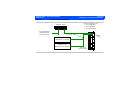
1
iE33
Service Manual
453561198931 Rev A December 2004
CSIP Level 1
Copyright © 2004 Koninklijke Philips Electronics N.V.
All rights reserved
About This Manual
Audience
This document and the information contained in it is strictly reserved for current Philips Medical
Systems (“Philips”) personnel, Philips licensed representatives, and Philips customers who have
purchased a valid service agreement for use by the customer’s designated in-house service
employee on equipment located at the customer’s designated site. Use of this document by
unauthorized persons is strictly prohibited. This document must be returned to Philips when the
user is no longer licensed and in any event upon Philips’ first written request.
This manual supports the field service maintenance and repair of the iE33 Ultrasound System.
The user of this document is a qualified ultrasound electronics technician who has completed
training classes on the system and its peripherals.
Manual Format
This manual is in Portable Document Format (PDF), for viewing on a laptop computer with
Acrobat Reader. A list of bookmarks functions as an additional table of contents. Those bookmarks, the table of contents, and cross-references use hypertext links to provide access to the
referenced information.
Conventions in
This Manual
The following conventions are used in this manual:
•
Hypertext links are blue.
•
All procedures are numbered, and all subprocedures are lettered. You must complete steps
in the sequence they are presented to ensure reliable results.
453561198931
CSIP Level 1
Service Manual
Questions
or Comments
Customer
Assistance
iE33 Service Manual
Page 2
About This Manual
•
Bulleted lists indicate general information about a function or procedure. They do not imply
a sequential procedure.
•
Control names and menu items or titles are spelled as they are on the system, and they
appear in bold text.
•
Symbols appear as they appear on the system.
•
An English system is assumed.
If you have questions about the service manual, or you discover an error in the manual, contact
Philips Ultrasound Technical Communications:
•
[email protected]
•
Technical Communications, MS 964, at the address below
Various support locations around the world can provide customers technical assistance with the
ultrasound system. Customers should contact the representative or sales office from which they
purchased the system or the nearest Philips Ultrasound office.
Philips Ultrasound
22100 Bothell-Everett Highway
Bothell, WA 98021-8431
USA
425-487-7000 or 800-426-2670
www.medical.philips.com
453561198931
CSIP Level 1
iE33 Service Manual
Page 3
About This Manual
“QLAB”, “DVS”, “SONOS”, “iU22”, “iE33”, “Chroma”, “Cineloop”, “Color Power Angio”, “Color Kinesis”, and “XRes” are
trademarks of Koninklijke Philips Electronics N.V.
Non-Philips product names may be trademarks or registered trademarks of their respective owners.
This document and the information contained in it is proprietary and confidential information of Philips Medical Systems (“Philips”)
and may not be reproduced, copied in whole or in part, adapted, modified, disclosed to others, or disseminated without the prior
written permission of the Philips Legal Department. Use of this document and the information contained in it is strictly reserved
for current Philips personnel and Philips customers who have a current and valid license from Philips for use by the customer’s
designated in-house service employee on equipment located at the customer’s designated site. Use of this document by unauthorized persons is strictly prohibited. Report violation of these requirements to the Philips Legal Department. This document must
be returned to Philips when the user is no longer licensed and in any event upon Philips’ first written request.
Philips provides this document without warranty of any kind, implied or expressed, including, but not limited to, the implied warranties of merchantability and fitness for a particular purpose.
Philips has taken care to ensure the accuracy of this document. However, Philips assumes no liability for errors or omissions and
reserves the right to make changes without further notice to any products herein to improve reliability, function, or design. Philips
may make improvements or changes in the products or programs described in this document at any time.
4535 611 98931
CSIP Level 1
iE33 Service Manual
Page 4
Contents
Contents
About This Manual . . . . . . . . . . . . . . . . . . . . . . . . . . . . . . . . . . . . . . . . . . . . . . . . . . . . . . . . . . . . . . . . . . . . . . . .1
Audience . . . . . . . . . . . . . . . . . . . . . . . . . . . . . . . . . . . . . . . . . . . . . . . . . . . . . . . . . . . . . . . . . . . . . . . . . . . . . . . . . . . . . . . 1
Manual Format . . . . . . . . . . . . . . . . . . . . . . . . . . . . . . . . . . . . . . . . . . . . . . . . . . . . . . . . . . . . . . . . . . . . . . . . . . . . . . . . . . 1
Conventions in This Manual . . . . . . . . . . . . . . . . . . . . . . . . . . . . . . . . . . . . . . . . . . . . . . . . . . . . . . . . . . . . . . . . . . . . . . . . 1
Service Manual Questions or Comments . . . . . . . . . . . . . . . . . . . . . . . . . . . . . . . . . . . . . . . . . . . . . . . . . . . . . . . . . . . . . 2
Customer Assistance . . . . . . . . . . . . . . . . . . . . . . . . . . . . . . . . . . . . . . . . . . . . . . . . . . . . . . . . . . . . . . . . . . . . . . . . . . . . . 2
Contents . . . . . . . . . . . . . . . . . . . . . . . . . . . . . . . . . . . . . . . . . . . . . . . . . . . . . . . . . . . . . . . . . . . . . . . . . . . . . . . . .4
General Information . . . . . . . . . . . . . . . . . . . . . . . . . . . . . . . . . . . . . . . . . . . . . . . . . . . . . . . . . . . . . . . . . . . . . .33
Introduction . . . . . . . . . . . . . . . . . . . . . . . . . . . . . . . . . . . . . . . . . . . . . . . . . . . . . . . . . . . . . . . . . . . . . . . . . . . . . . . . . . . . . . 33
Figure 1-1 iE33 Ultrasound System . . . . . . . . . . . . . . . . . . . . . . . . . . . . . . . . . . . . . . . . . . . . . . . . . . . . . . . . . . . . . . 34
Transducers . . . . . . . . . . . . . . . . . . . . . . . . . . . . . . . . . . . . . . . . . . . . . . . . . . . . . . . . . . . . . . . . . . . . . . . . . . . . . . . . . . . . . . 35
Physical Description . . . . . . . . . . . . . . . . . . . . . . . . . . . . . . . . . . . . . . . . . . . . . . . . . . . . . . . . . . . . . . . . . . . . . . . . . . . . . . . . 35
Figure 1-2 Control Panel and Keyboard . . . . . . . . . . . . . . . . . . . . . . . . . . . . . . . . . . . . . . . . . . . . . . . . . . . . . . . . . . 37
Figure 1-3 System Peripherals . . . . . . . . . . . . . . . . . . . . . . . . . . . . . . . . . . . . . . . . . . . . . . . . . . . . . . . . . . . . . . . . . . 39
Safety Requirements . . . . . . . . . . . . . . . . . . . . . . . . . . . . . . . . . . . . . . . . . . . . . . . . . . . . . . . . . . . . . . . . . . . . . . . . . . . . . . . . 40
Supplies and Accessories . . . . . . . . . . . . . . . . . . . . . . . . . . . . . . . . . . . . . . . . . . . . . . . . . . . . . . . . . . . . . . . . . . . . . . . . . . . . 41
Specifications
. . . . . . . . . . . . . . . . . . . . . . . . . . . . . . . . . . . . . . . . . . . . . . . . . . . . . . . . . . . . . . . . . . . . . . . . . . .42
Introduction . . . . . . . . . . . . . . . . . . . . . . . . . . . . . . . . . . . . . . . . . . . . . . . . . . . . . . . . . . . . . . . . . . . . . . . . . . . . . . . . . . . . . . 42
Physical Dimensions . . . . . . . . . . . . . . . . . . . . . . . . . . . . . . . . . . . . . . . . . . . . . . . . . . . . . . . . . . . . . . . . . . . . . . . . . . . . . . . . 42
4535 611 98931
CSIP Level 1
iE33 Service Manual
Page 5
Contents
Imaging Modes . . . . . . . . . . . . . . . . . . . . . . . . . . . . . . . . . . . . . . . . . . . . . . . . . . . . . . . . . . . . . . . . . . . . . . . . . . . . . . . . . . . . 42
Applications . . . . . . . . . . . . . . . . . . . . . . . . . . . . . . . . . . . . . . . . . . . . . . . . . . . . . . . . . . . . . . . . . . . . . . . . . . . . . . . . . . . . . . 43
Imaging Features . . . . . . . . . . . . . . . . . . . . . . . . . . . . . . . . . . . . . . . . . . . . . . . . . . . . . . . . . . . . . . . . . . . . . . . . . . . . . . . . . . . 43
System Cart . . . . . . . . . . . . . . . . . . . . . . . . . . . . . . . . . . . . . . . . . . . . . . . . . . . . . . . . . . . . . . . . . . . . . . . . . . . . . . . . . . . . . . 44
Control Panel and User Interface . . . . . . . . . . . . . . . . . . . . . . . . . . . . . . . . . . . . . . . . . . . . . . . . . . . . . . . . . . . . . . . . . . . . . 45
Stress Echo Protocols . . . . . . . . . . . . . . . . . . . . . . . . . . . . . . . . . . . . . . . . . . . . . . . . . . . . . . . . . . . . . . . . . . . . . . . . . . . . . . 46
Quick Save Feature . . . . . . . . . . . . . . . . . . . . . . . . . . . . . . . . . . . . . . . . . . . . . . . . . . . . . . . . . . . . . . . . . . . . . . . . . . . . . . . . . 47
Image Presentation . . . . . . . . . . . . . . . . . . . . . . . . . . . . . . . . . . . . . . . . . . . . . . . . . . . . . . . . . . . . . . . . . . . . . . . . . . . . . . . . . 47
Cineloop Review . . . . . . . . . . . . . . . . . . . . . . . . . . . . . . . . . . . . . . . . . . . . . . . . . . . . . . . . . . . . . . . . . . . . . . . . . . . . . . . . . . 47
Physio . . . . . . . . . . . . . . . . . . . . . . . . . . . . . . . . . . . . . . . . . . . . . . . . . . . . . . . . . . . . . . . . . . . . . . . . . . . . . . . . . . . . . . . . . . . 48
System Architecture . . . . . . . . . . . . . . . . . . . . . . . . . . . . . . . . . . . . . . . . . . . . . . . . . . . . . . . . . . . . . . . . . . . . . . . . . . . . . . . . 48
Display Annotation . . . . . . . . . . . . . . . . . . . . . . . . . . . . . . . . . . . . . . . . . . . . . . . . . . . . . . . . . . . . . . . . . . . . . . . . . . . . . . . . . 49
Transducers . . . . . . . . . . . . . . . . . . . . . . . . . . . . . . . . . . . . . . . . . . . . . . . . . . . . . . . . . . . . . . . . . . . . . . . . . . . . . . . . . . . . . . 50
Measurements and Analysis . . . . . . . . . . . . . . . . . . . . . . . . . . . . . . . . . . . . . . . . . . . . . . . . . . . . . . . . . . . . . . . . . . . . . . . . . . 51
Measurement Tools and General Description . . . . . . . . . . . . . . . . . . . . . . . . . . . . . . . . . . . . . . . . . . . . . . . . . . . . . . . . 51
QLAB Advanced Quantification Plug-in Options . . . . . . . . . . . . . . . . . . . . . . . . . . . . . . . . . . . . . . . . . . . . . . . . . . . . . . 52
Clinical Option Analysis Packages . . . . . . . . . . . . . . . . . . . . . . . . . . . . . . . . . . . . . . . . . . . . . . . . . . . . . . . . . . . . . . . . . . 55
High Q Automatic Doppler Analysis . . . . . . . . . . . . . . . . . . . . . . . . . . . . . . . . . . . . . . . . . . . . . . . . . . . . . . . . . . . . . . . . 56
Connectivity . . . . . . . . . . . . . . . . . . . . . . . . . . . . . . . . . . . . . . . . . . . . . . . . . . . . . . . . . . . . . . . . . . . . . . . . . . . . . . . . . . . . . . 57
Video Monitor . . . . . . . . . . . . . . . . . . . . . . . . . . . . . . . . . . . . . . . . . . . . . . . . . . . . . . . . . . . . . . . . . . . . . . . . . . . . . . . . . . . . 58
Peripheral Devices/Exam Documentation . . . . . . . . . . . . . . . . . . . . . . . . . . . . . . . . . . . . . . . . . . . . . . . . . . . . . . . . . . . . . . . 59
4535 611 98931
CSIP Level 1
iE33 Service Manual
Page 6
Contents
Electrical Power/Video Parameters . . . . . . . . . . . . . . . . . . . . . . . . . . . . . . . . . . . . . . . . . . . . . . . . . . . . . . . . . . . . . . . . . . . . 59
Environmental Requirements . . . . . . . . . . . . . . . . . . . . . . . . . . . . . . . . . . . . . . . . . . . . . . . . . . . . . . . . . . . . . . . . . . . . . . . . . 59
Safety . . . . . . . . . . . . . . . . . . . . . . . . . . . . . . . . . . . . . . . . . . . . . . . . . . . . . . . . . . . . . . . . . . . . . . . . . . . . . . . . . .60
Introduction . . . . . . . . . . . . . . . . . . . . . . . . . . . . . . . . . . . . . . . . . . . . . . . . . . . . . . . . . . . . . . . . . . . . . . . . . . . . . . . . . . . . . . 60
Electrical Safety . . . . . . . . . . . . . . . . . . . . . . . . . . . . . . . . . . . . . . . . . . . . . . . . . . . . . . . . . . . . . . . . . . . . . . . . . . . . . . . . . . . . 60
Mechanical Safety . . . . . . . . . . . . . . . . . . . . . . . . . . . . . . . . . . . . . . . . . . . . . . . . . . . . . . . . . . . . . . . . . . . . . . . . . . . . . . . . . . 63
Environmental Safety . . . . . . . . . . . . . . . . . . . . . . . . . . . . . . . . . . . . . . . . . . . . . . . . . . . . . . . . . . . . . . . . . . . . . . . . . . . . . . . 65
Equipment Protection . . . . . . . . . . . . . . . . . . . . . . . . . . . . . . . . . . . . . . . . . . . . . . . . . . . . . . . . . . . . . . . . . . . . . . . . . . . . . . . 65
Symbols . . . . . . . . . . . . . . . . . . . . . . . . . . . . . . . . . . . . . . . . . . . . . . . . . . . . . . . . . . . . . . . . . . . . . . . . . . . . . . . . . . . . . . . . . . 66
Theory of Operation . . . . . . . . . . . . . . . . . . . . . . . . . . . . . . . . . . . . . . . . . . . . . . . . . . . . . . . . . . . . . . . . . . . . . .69
Introduction . . . . . . . . . . . . . . . . . . . . . . . . . . . . . . . . . . . . . . . . . . . . . . . . . . . . . . . . . . . . . . . . . . . . . . . . . . . . . . . . . . . . . . 69
Operating System . . . . . . . . . . . . . . . . . . . . . . . . . . . . . . . . . . . . . . . . . . . . . . . . . . . . . . . . . . . . . . . . . . . . . . . . . . . . . . . . . 69
System Functional Architecture . . . . . . . . . . . . . . . . . . . . . . . . . . . . . . . . . . . . . . . . . . . . . . . . . . . . . . . . . . . . . . . . . . . . . . 69
Signal Flow . . . . . . . . . . . . . . . . . . . . . . . . . . . . . . . . . . . . . . . . . . . . . . . . . . . . . . . . . . . . . . . . . . . . . . . . . . . . . . . . . . . . . . . 70
Physical Structure . . . . . . . . . . . . . . . . . . . . . . . . . . . . . . . . . . . . . . . . . . . . . . . . . . . . . . . . . . . . . . . . . . . . . . . . . . . . . . . . . . 71
Figure 4-1 iE33 Physical Structure . . . . . . . . . . . . . . . . . . . . . . . . . . . . . . . . . . . . . . . . . . . . . . . . . . . . . . . . . . . . . . . 71
Power Subsystem . . . . . . . . . . . . . . . . . . . . . . . . . . . . . . . . . . . . . . . . . . . . . . . . . . . . . . . . . . . . . . . . . . . . . . . . . . . . . . . 72
Figure 4-2 Power Subsystem Block Diagram . . . . . . . . . . . . . . . . . . . . . . . . . . . . . . . . . . . . . . . . . . . . . . . . . . . . . . . 75
Figure 4-3 On/Standby Switch and Power Subsystem Block Diagram . . . . . . . . . . . . . . . . . . . . . . . . . . . . . . . . . . . 76
Figure 4-4 HV Power Supply Block Diagram . . . . . . . . . . . . . . . . . . . . . . . . . . . . . . . . . . . . . . . . . . . . . . . . . . . . . . . 80
Control Subsystem . . . . . . . . . . . . . . . . . . . . . . . . . . . . . . . . . . . . . . . . . . . . . . . . . . . . . . . . . . . . . . . . . . . . . . . . . . . . . . 81
4535 611 98931
CSIP Level 1
iE33 Service Manual
Page 7
Contents
Table 4-1 Host Hard Drive Partitioning . . . . . . . . . . . . . . . . . . . . . . . . . . . . . . . . . . . . . . . . . . . . . . . . . . . . . . . . . . 85
Acquisition Subsystem . . . . . . . . . . . . . . . . . . . . . . . . . . . . . . . . . . . . . . . . . . . . . . . . . . . . . . . . . . . . . . . . . . . . . . . . . . . 86
Signal Processing Subsystem . . . . . . . . . . . . . . . . . . . . . . . . . . . . . . . . . . . . . . . . . . . . . . . . . . . . . . . . . . . . . . . . . . . . . . 94
Output Power Monitor Theory . . . . . . . . . . . . . . . . . . . . . . . . . . . . . . . . . . . . . . . . . . . . . . . . . . . . . . . . . . . . . . . . . . . . . . 96
Acoustic Power and Intensity Manager (APIM) . . . . . . . . . . . . . . . . . . . . . . . . . . . . . . . . . . . . . . . . . . . . . . . . . . . . . . . . . . . 97
Temperature Monitoring . . . . . . . . . . . . . . . . . . . . . . . . . . . . . . . . . . . . . . . . . . . . . . . . . . . . . . . . . . . . . . . . . . . . . . . . . . . . 97
X3-1 Transducer Theory . . . . . . . . . . . . . . . . . . . . . . . . . . . . . . . . . . . . . . . . . . . . . . . . . . . . . . . . . . . . . . . . . . . . . . . . . . . . 98
Bus Functions . . . . . . . . . . . . . . . . . . . . . . . . . . . . . . . . . . . . . . . . . . . . . . . . . . . . . . . . . . . . . . . . . . . . . . . . . . . . . . . . . . . . . 99
Platform Subsystem Buses . . . . . . . . . . . . . . . . . . . . . . . . . . . . . . . . . . . . . . . . . . . . . . . . . . . . . . . . . . . . . . . . . . . . . . . . 99
Inter-Card Cage Buses . . . . . . . . . . . . . . . . . . . . . . . . . . . . . . . . . . . . . . . . . . . . . . . . . . . . . . . . . . . . . . . . . . . . . . . . . 100
Front-End Buses . . . . . . . . . . . . . . . . . . . . . . . . . . . . . . . . . . . . . . . . . . . . . . . . . . . . . . . . . . . . . . . . . . . . . . . . . . . . . . . 101
Data Paths . . . . . . . . . . . . . . . . . . . . . . . . . . . . . . . . . . . . . . . . . . . . . . . . . . . . . . . . . . . . . . . . . . . . . . . . . . . . . . . . . . . . . . . 102
Figure 4-5 2D Echo and M-mode Data Path Block Diagram . . . . . . . . . . . . . . . . . . . . . . . . . . . . . . . . . . . . . . . . . . 103
Installation . . . . . . . . . . . . . . . . . . . . . . . . . . . . . . . . . . . . . . . . . . . . . . . . . . . . . . . . . . . . . . . . . . . . . . . . . . . . .104
Introduction . . . . . . . . . . . . . . . . . . . . . . . . . . . . . . . . . . . . . . . . . . . . . . . . . . . . . . . . . . . . . . . . . . . . . . . . . . . . . . . . . . . . . 104
Materials and Equipment . . . . . . . . . . . . . . . . . . . . . . . . . . . . . . . . . . . . . . . . . . . . . . . . . . . . . . . . . . . . . . . . . . . . . . . . 104
Site Inspection . . . . . . . . . . . . . . . . . . . . . . . . . . . . . . . . . . . . . . . . . . . . . . . . . . . . . . . . . . . . . . . . . . . . . . . . . . . . . . . . . . . . 105
Environmental Requirements . . . . . . . . . . . . . . . . . . . . . . . . . . . . . . . . . . . . . . . . . . . . . . . . . . . . . . . . . . . . . . . . . . . . 105
➤ To determine if the site meets environmental requirements . . . . . . . . . . . . . . . . . . . . . . . . . . . . . . . . . . . . . . . . . 105
Table 5-1 System Specifications (Crated/Uncrated) . . . . . . . . . . . . . . . . . . . . . . . . . . . . . . . . . . . . . . . . . . . . . . . . 106
Electrical Power Requirements . . . . . . . . . . . . . . . . . . . . . . . . . . . . . . . . . . . . . . . . . . . . . . . . . . . . . . . . . . . . . . . . . . . 107
4535 611 98931
CSIP Level 1
iE33 Service Manual
Page 8
Contents
Image Management Network Requirements . . . . . . . . . . . . . . . . . . . . . . . . . . . . . . . . . . . . . . . . . . . . . . . . . . . . . . . . 107
➤ Perform the following steps before installing the DICOM Connectivity option . . . . . . . . . . . . . . . . . . . . . . . . . . 107
System Uncrating . . . . . . . . . . . . . . . . . . . . . . . . . . . . . . . . . . . . . . . . . . . . . . . . . . . . . . . . . . . . . . . . . . . . . . . . . . . . . . . . . 108
Crate Inspection . . . . . . . . . . . . . . . . . . . . . . . . . . . . . . . . . . . . . . . . . . . . . . . . . . . . . . . . . . . . . . . . . . . . . . . . . . . . . . 108
➤ To inspect the shipping crate before unpacking the system . . . . . . . . . . . . . . . . . . . . . . . . . . . . . . . . . . . . . . . . . . 108
Uncrating Procedure . . . . . . . . . . . . . . . . . . . . . . . . . . . . . . . . . . . . . . . . . . . . . . . . . . . . . . . . . . . . . . . . . . . . . . . . . . . 108
System Inspection . . . . . . . . . . . . . . . . . . . . . . . . . . . . . . . . . . . . . . . . . . . . . . . . . . . . . . . . . . . . . . . . . . . . . . . . . . . . . . . . . 109
Introduction . . . . . . . . . . . . . . . . . . . . . . . . . . . . . . . . . . . . . . . . . . . . . . . . . . . . . . . . . . . . . . . . . . . . . . . . . . . . . . . . . . 109
General Inspection
. . . . . . . . . . . . . . . . . . . . . . . . . . . . . . . . . . . . . . . . . . . . . . . . . . . . . . . . . . . . . . . . . . . . . . . . . . . . 109
➤ To perform the general inspection . . . . . . . . . . . . . . . . . . . . . . . . . . . . . . . . . . . . . . . . . . . . . . . . . . . . . . . . . . . . . 109
System Powerup . . . . . . . . . . . . . . . . . . . . . . . . . . . . . . . . . . . . . . . . . . . . . . . . . . . . . . . . . . . . . . . . . . . . . . . . . . . . . . . . . . 110
➤ To power up the system . . . . . . . . . . . . . . . . . . . . . . . . . . . . . . . . . . . . . . . . . . . . . . . . . . . . . . . . . . . . . . . . . . . . . 110
Peripheral Installations . . . . . . . . . . . . . . . . . . . . . . . . . . . . . . . . . . . . . . . . . . . . . . . . . . . . . . . . . . . . . . . . . . . . . . . . . . . . . 111
VCRs . . . . . . . . . . . . . . . . . . . . . . . . . . . . . . . . . . . . . . . . . . . . . . . . . . . . . . . . . . . . . . . . . . . . . . . . . . . . . . . . . . . . . . . . 111
➤ To change the VCR menu settings . . . . . . . . . . . . . . . . . . . . . . . . . . . . . . . . . . . . . . . . . . . . . . . . . . . . . . . . . . . . . . 112
Table 5-3 Mitsubishi HS-MD3000U/E and HS-MD3000UA/EA VCR RS-232 Interface Adapter Switch Settings . 113
Table 5-2 Mitsubishi HS-MD3000UA/EA VCR Control Settings . . . . . . . . . . . . . . . . . . . . . . . . . . . . . . . . . . . . . . 113
Table 5-4 Mitsubishi HS-MD3000UA/EA VCR Menu Settings . . . . . . . . . . . . . . . . . . . . . . . . . . . . . . . . . . . . . . . . 114
➤ To change the VCR hidden menu settings . . . . . . . . . . . . . . . . . . . . . . . . . . . . . . . . . . . . . . . . . . . . . . . . . . . . . . . 115
Table 5-5 Mitsubishi HS-MD3000U/E and HS-MD3000UA/EA VCR Hidden Menu Control Settings . . . . . . . . . 116
Printers . . . . . . . . . . . . . . . . . . . . . . . . . . . . . . . . . . . . . . . . . . . . . . . . . . . . . . . . . . . . . . . . . . . . . . . . . . . . . . . . . . . . . . 117
4535 611 98931
CSIP Level 1
iE33 Service Manual
Page 9
Contents
➤ To set up a color or a black-and-white printer . . . . . . . . . . . . . . . . . . . . . . . . . . . . . . . . . . . . . . . . . . . . . . . . . . . . 117
Table 5-6 Sony UPD-23MD Digital Color Printer Driver Settings . . . . . . . . . . . . . . . . . . . . . . . . . . . . . . . . . . . . 119
External Monitor or Other Display Device . . . . . . . . . . . . . . . . . . . . . . . . . . . . . . . . . . . . . . . . . . . . . . . . . . . . . . . . . . 121
Connectivity Information . . . . . . . . . . . . . . . . . . . . . . . . . . . . . . . . . . . . . . . . . . . . . . . . . . . . . . . . . . . . . . . . . . . . . . . . . . . 121
Preparation . . . . . . . . . . . . . . . . . . . . . . . . . . . . . . . . . . . . . . . . . . . . . . . . . . . . . . . . . . . . . . . . . . . . . . . . . . . . . . . . . . . 121
➤ To prepare for an on-site network configuration visit . . . . . . . . . . . . . . . . . . . . . . . . . . . . . . . . . . . . . . . . . . . . . . 121
Ethernet Connection . . . . . . . . . . . . . . . . . . . . . . . . . . . . . . . . . . . . . . . . . . . . . . . . . . . . . . . . . . . . . . . . . . . . . . . . . . . 122
Figure 5-1 Ethernet Connection Diagram . . . . . . . . . . . . . . . . . . . . . . . . . . . . . . . . . . . . . . . . . . . . . . . . . . . . . . . . 123
Figure 5-2 Tech Admin Connectivity Tools . . . . . . . . . . . . . . . . . . . . . . . . . . . . . . . . . . . . . . . . . . . . . . . . . . . . . . 124
Ultrasound System Configuration . . . . . . . . . . . . . . . . . . . . . . . . . . . . . . . . . . . . . . . . . . . . . . . . . . . . . . . . . . . . . . . . . 125
➤ To configure the ultrasound system for a network connection . . . . . . . . . . . . . . . . . . . . . . . . . . . . . . . . . . . . . . . 125
Adding DICOM Printers or Servers . . . . . . . . . . . . . . . . . . . . . . . . . . . . . . . . . . . . . . . . . . . . . . . . . . . . . . . . . . . . . . . 126
➤ To add a network device (printer, server, or archive device) . . . . . . . . . . . . . . . . . . . . . . . . . . . . . . . . . . . . . . . . 126
Selecting Devices . . . . . . . . . . . . . . . . . . . . . . . . . . . . . . . . . . . . . . . . . . . . . . . . . . . . . . . . . . . . . . . . . . . . . . . . . . . . . . 127
➤ To select a printer and edit the printer settings . . . . . . . . . . . . . . . . . . . . . . . . . . . . . . . . . . . . . . . . . . . . . . . . . . . 127
➤ To select an archive device, storage commit, or structured report device . . . . . . . . . . . . . . . . . . . . . . . . . . . . . . 128
➤ To select a worklist or performed procedure step server . . . . . . . . . . . . . . . . . . . . . . . . . . . . . . . . . . . . . . . . . . . 128
Verifying Devices . . . . . . . . . . . . . . . . . . . . . . . . . . . . . . . . . . . . . . . . . . . . . . . . . . . . . . . . . . . . . . . . . . . . . . . . . . . . . . 129
➤ To verify network devices . . . . . . . . . . . . . . . . . . . . . . . . . . . . . . . . . . . . . . . . . . . . . . . . . . . . . . . . . . . . . . . . . . . . 129
DVD Configurations . . . . . . . . . . . . . . . . . . . . . . . . . . . . . . . . . . . . . . . . . . . . . . . . . . . . . . . . . . . . . . . . . . . . . . . . . . . . 129
➤ To select what type of information is exported to DVD . . . . . . . . . . . . . . . . . . . . . . . . . . . . . . . . . . . . . . . . . . . . 129
4535 611 98931
CSIP Level 1
iE33 Service Manual
Page 10
Contents
Hard Drive Maintenance . . . . . . . . . . . . . . . . . . . . . . . . . . . . . . . . . . . . . . . . . . . . . . . . . . . . . . . . . . . . . . . . . . . . . . . . 130
➤ To specify the auto-delete exam capabilities for maintaining the hard drive . . . . . . . . . . . . . . . . . . . . . . . . . . . . . 130
Printer and Image Capture Configurations . . . . . . . . . . . . . . . . . . . . . . . . . . . . . . . . . . . . . . . . . . . . . . . . . . . . . . . . . . 130
➤ To set up printer and capture parameters . . . . . . . . . . . . . . . . . . . . . . . . . . . . . . . . . . . . . . . . . . . . . . . . . . . . . . . 130
Final Test Procedure . . . . . . . . . . . . . . . . . . . . . . . . . . . . . . . . . . . . . . . . . . . . . . . . . . . . . . . . . . . . . . . . . . . . . . . . . . . . . . 131
➤ To perform the final test procedure . . . . . . . . . . . . . . . . . . . . . . . . . . . . . . . . . . . . . . . . . . . . . . . . . . . . . . . . . . . . 131
Additional Image Adjustments . . . . . . . . . . . . . . . . . . . . . . . . . . . . . . . . . . . . . . . . . . . . . . . . . . . . . . . . . . . . . . . . . . . . . . . 131
Display Image Quality . . . . . . . . . . . . . . . . . . . . . . . . . . . . . . . . . . . . . . . . . . . . . . . . . . . . . . . . . . . . . . . . . . . . . . . . . . . 131
➤ To adjust display image quality . . . . . . . . . . . . . . . . . . . . . . . . . . . . . . . . . . . . . . . . . . . . . . . . . . . . . . . . . . . . . . . . . 131
Loop Frame Rate . . . . . . . . . . . . . . . . . . . . . . . . . . . . . . . . . . . . . . . . . . . . . . . . . . . . . . . . . . . . . . . . . . . . . . . . . . . . . . 132
➤ To change the loop frame rate . . . . . . . . . . . . . . . . . . . . . . . . . . . . . . . . . . . . . . . . . . . . . . . . . . . . . . . . . . . . . . . . 132
Print Image Quality . . . . . . . . . . . . . . . . . . . . . . . . . . . . . . . . . . . . . . . . . . . . . . . . . . . . . . . . . . . . . . . . . . . . . . . . . . . . . 133
➤ To adjust print image quality . . . . . . . . . . . . . . . . . . . . . . . . . . . . . . . . . . . . . . . . . . . . . . . . . . . . . . . . . . . . . . . . . . 133
Installation Completion . . . . . . . . . . . . . . . . . . . . . . . . . . . . . . . . . . . . . . . . . . . . . . . . . . . . . . . . . . . . . . . . . . . . . . . . . . . . 133
Final Inspection . . . . . . . . . . . . . . . . . . . . . . . . . . . . . . . . . . . . . . . . . . . . . . . . . . . . . . . . . . . . . . . . . . . . . . . . . . . . . . . 133
System Presentation . . . . . . . . . . . . . . . . . . . . . . . . . . . . . . . . . . . . . . . . . . . . . . . . . . . . . . . . . . . . . . . . . . . . . . . . . . . 134
Final Presentation . . . . . . . . . . . . . . . . . . . . . . . . . . . . . . . . . . . . . . . . . . . . . . . . . . . . . . . . . . . . . . . . . . . . . . . . . . . . . . 137
➤ To present the system to the customer . . . . . . . . . . . . . . . . . . . . . . . . . . . . . . . . . . . . . . . . . . . . . . . . . . . . . . . . . 137
Connectivity Worksheet . . . . . . . . . . . . . . . . . . . . . . . . . . . . . . . . . . . . . . . . . . . . . . . . . . . . . . . . . . . . . . . . . . . . . . . . . . . 137
Table 5-7 Connectivity Worksheet . . . . . . . . . . . . . . . . . . . . . . . . . . . . . . . . . . . . . . . . . . . . . . . . . . . . . . . . . . . . 138
Installation Checklist . . . . . . . . . . . . . . . . . . . . . . . . . . . . . . . . . . . . . . . . . . . . . . . . . . . . . . . . . . . . . . . . . . . . . . . . . . . . . . . 140
4535 611 98931
CSIP Level 1
iE33 Service Manual
Page 11
Contents
Installation Procedures . . . . . . . . . . . . . . . . . . . . . . . . . . . . . . . . . . . . . . . . . . . . . . . . . . . . . . . . . . . . . . . . . . . . . . . . . . . . . 142
Figure 5-3 Installation Procedure List . . . . . . . . . . . . . . . . . . . . . . . . . . . . . . . . . . . . . . . . . . . . . . . . . . . . . . . . . . . 142
Uncrating the iE33 Ultrasound System . . . . . . . . . . . . . . . . . . . . . . . . . . . . . . . . . . . . . . . . . . . . . . . . . . . . . . . . . . . . . 143
Figure 5-4 Cutting the Plastic Banding . . . . . . . . . . . . . . . . . . . . . . . . . . . . . . . . . . . . . . . . . . . . . . . . . . . . . . . . . . . 143
➤ To uncrate the iE33 Ultrasound System . . . . . . . . . . . . . . . . . . . . . . . . . . . . . . . . . . . . . . . . . . . . . . . . . . . . . . . . . 143
Figure 5-5 Removing the Corrugated Cover . . . . . . . . . . . . . . . . . . . . . . . . . . . . . . . . . . . . . . . . . . . . . . . . . . . . . . 144
Figure 5-6 Removing the Braces . . . . . . . . . . . . . . . . . . . . . . . . . . . . . . . . . . . . . . . . . . . . . . . . . . . . . . . . . . . . . . . 145
Figure 5-7 Cutting the Tape on the Seams . . . . . . . . . . . . . . . . . . . . . . . . . . . . . . . . . . . . . . . . . . . . . . . . . . . . . . . 146
Figure 5-8 Removing One of the Corrugated Wraps . . . . . . . . . . . . . . . . . . . . . . . . . . . . . . . . . . . . . . . . . . . . . . . 147
Figure 5-9 Removing the Second Corrugated Wrap . . . . . . . . . . . . . . . . . . . . . . . . . . . . . . . . . . . . . . . . . . . . . . . . 148
Figure 5-10 Removing the Ramp from the Pallet . . . . . . . . . . . . . . . . . . . . . . . . . . . . . . . . . . . . . . . . . . . . . . . . . . 149
Figure 5-11 Placing the Ramp . . . . . . . . . . . . . . . . . . . . . . . . . . . . . . . . . . . . . . . . . . . . . . . . . . . . . . . . . . . . . . . . . . 150
Figure 5-12 Removing the System Rear Anchor Hardware . . . . . . . . . . . . . . . . . . . . . . . . . . . . . . . . . . . . . . . . . . 151
Figure 5-13 Removing the Ring Connectors . . . . . . . . . . . . . . . . . . . . . . . . . . . . . . . . . . . . . . . . . . . . . . . . . . . . . . 152
Figure 5-14 Removing the Front Hold-Down Brace . . . . . . . . . . . . . . . . . . . . . . . . . . . . . . . . . . . . . . . . . . . . . . . . 153
Figure 5-15 Preparing to Roll the System off the Pallet . . . . . . . . . . . . . . . . . . . . . . . . . . . . . . . . . . . . . . . . . . . . . 154
Figure 5-16 Rolling the System off the Pallet . . . . . . . . . . . . . . . . . . . . . . . . . . . . . . . . . . . . . . . . . . . . . . . . . . . . . . 155
Crating the iE33 Ultrasound System . . . . . . . . . . . . . . . . . . . . . . . . . . . . . . . . . . . . . . . . . . . . . . . . . . . . . . . . . . . . . . . 156
Figure 5-17 Placing the Ramp . . . . . . . . . . . . . . . . . . . . . . . . . . . . . . . . . . . . . . . . . . . . . . . . . . . . . . . . . . . . . . . . . . 156
➤ To crate the iE33 Ultrasound System . . . . . . . . . . . . . . . . . . . . . . . . . . . . . . . . . . . . . . . . . . . . . . . . . . . . . . . . . . . 156
Figure 5-18 Locking the Right-Rear Caster . . . . . . . . . . . . . . . . . . . . . . . . . . . . . . . . . . . . . . . . . . . . . . . . . . . . . . . 157
4535 611 98931
CSIP Level 1
iE33 Service Manual
Page 12
Contents
Figure 5-19 Supporting the Monitor and Arm . . . . . . . . . . . . . . . . . . . . . . . . . . . . . . . . . . . . . . . . . . . . . . . . . . . . . 158
Figure 5-20 Covering the System with an Anti-Static Bag . . . . . . . . . . . . . . . . . . . . . . . . . . . . . . . . . . . . . . . . . . . . 159
Figure 5-21 Rolling the System onto the Pallet . . . . . . . . . . . . . . . . . . . . . . . . . . . . . . . . . . . . . . . . . . . . . . . . . . . . 160
Figure 5-22 Swiveling the Front Casters . . . . . . . . . . . . . . . . . . . . . . . . . . . . . . . . . . . . . . . . . . . . . . . . . . . . . . . . . 161
Figure 5-23 Installing the Front Hold-Down Brace . . . . . . . . . . . . . . . . . . . . . . . . . . . . . . . . . . . . . . . . . . . . . . . . . 162
Figure 5-24 Installing the Control Panel Support . . . . . . . . . . . . . . . . . . . . . . . . . . . . . . . . . . . . . . . . . . . . . . . . . . 163
Figure 5-25 Installing the Handle Bar Brace . . . . . . . . . . . . . . . . . . . . . . . . . . . . . . . . . . . . . . . . . . . . . . . . . . . . . . . 164
Figure 5-26 Installing the Ramp onto the Pallet . . . . . . . . . . . . . . . . . . . . . . . . . . . . . . . . . . . . . . . . . . . . . . . . . . . . 165
Figure 5-27 Installing the System Rear Anchor Hardware . . . . . . . . . . . . . . . . . . . . . . . . . . . . . . . . . . . . . . . . . . . 166
Figure 5-28 Placing the First Corrugated Wrap . . . . . . . . . . . . . . . . . . . . . . . . . . . . . . . . . . . . . . . . . . . . . . . . . . . 167
Figure 5-29 Placing the Second Corrugated Wrap . . . . . . . . . . . . . . . . . . . . . . . . . . . . . . . . . . . . . . . . . . . . . . . . . 168
Figure 5-30 Taping the Seams on the Corrugated Wrap . . . . . . . . . . . . . . . . . . . . . . . . . . . . . . . . . . . . . . . . . . . . 169
Figure 5-31 Folding the Top System Support Braces . . . . . . . . . . . . . . . . . . . . . . . . . . . . . . . . . . . . . . . . . . . . . . . 170
Figure 5-32 Placing the Top System Support Braces . . . . . . . . . . . . . . . . . . . . . . . . . . . . . . . . . . . . . . . . . . . . . . . . 171
Figure 5-33 Placing the Monitor Arm Brace . . . . . . . . . . . . . . . . . . . . . . . . . . . . . . . . . . . . . . . . . . . . . . . . . . . . . . 172
Figure 5-34 Placing the Corrugated Cover . . . . . . . . . . . . . . . . . . . . . . . . . . . . . . . . . . . . . . . . . . . . . . . . . . . . . . . 173
Figure 5-35 Banding the System Crate . . . . . . . . . . . . . . . . . . . . . . . . . . . . . . . . . . . . . . . . . . . . . . . . . . . . . . . . . . 174
Shipping Strap Brackets . . . . . . . . . . . . . . . . . . . . . . . . . . . . . . . . . . . . . . . . . . . . . . . . . . . . . . . . . . . . . . . . . . . . . . . . . 175
Figure 5-36 Removing Shipping Strap Brackets . . . . . . . . . . . . . . . . . . . . . . . . . . . . . . . . . . . . . . . . . . . . . . . . . . . . 175
➤ To remove the shipping strap brackets . . . . . . . . . . . . . . . . . . . . . . . . . . . . . . . . . . . . . . . . . . . . . . . . . . . . . . . . . . 175
Video Monitor Articulation Arm . . . . . . . . . . . . . . . . . . . . . . . . . . . . . . . . . . . . . . . . . . . . . . . . . . . . . . . . . . . . . . . . . . 176
4535 611 98931
CSIP Level 1
iE33 Service Manual
Page 13
Contents
Figure 5-37 Unlocking the Articulation Arm . . . . . . . . . . . . . . . . . . . . . . . . . . . . . . . . . . . . . . . . . . . . . . . . . . . . . . 176
➤ To unlock the video monitor articulation arm . . . . . . . . . . . . . . . . . . . . . . . . . . . . . . . . . . . . . . . . . . . . . . . . . . . . 176
Lower OEM Deck and Strapping (Single OEM) . . . . . . . . . . . . . . . . . . . . . . . . . . . . . . . . . . . . . . . . . . . . . . . . . . . . . . . 177
Figure 5-38 Preparing Lower OEM Deck Strapping . . . . . . . . . . . . . . . . . . . . . . . . . . . . . . . . . . . . . . . . . . . . . . . . 177
➤ To install or remove the lower deck OEM . . . . . . . . . . . . . . . . . . . . . . . . . . . . . . . . . . . . . . . . . . . . . . . . . . . . . . . 177
Figure 5-39 Removing the OEM Tray . . . . . . . . . . . . . . . . . . . . . . . . . . . . . . . . . . . . . . . . . . . . . . . . . . . . . . . . . . . 178
Figure 5-40 Lower Deck Anchors and Drop Covers . . . . . . . . . . . . . . . . . . . . . . . . . . . . . . . . . . . . . . . . . . . . . . . 179
Figure 5-41 Installing the Lower Deck Cable Cover . . . . . . . . . . . . . . . . . . . . . . . . . . . . . . . . . . . . . . . . . . . . . . . . 180
Figure 5-42 Placing the VCR on the Lower OEM Deck . . . . . . . . . . . . . . . . . . . . . . . . . . . . . . . . . . . . . . . . . . . . . 181
Figure 5-43 Installing Lower Deck OEM Strapping Over the VCR . . . . . . . . . . . . . . . . . . . . . . . . . . . . . . . . . . . . 182
Figure 5-44 Securing Lower OEM Deck Strapping . . . . . . . . . . . . . . . . . . . . . . . . . . . . . . . . . . . . . . . . . . . . . . . . . 183
Figure 5-45 Attaching the Lower OEM Shelf to the Upper OEM Shelf . . . . . . . . . . . . . . . . . . . . . . . . . . . . . . . . . 184
Figure 5-46 Installing Lower OEM Deck Shelf Unit . . . . . . . . . . . . . . . . . . . . . . . . . . . . . . . . . . . . . . . . . . . . . . . . . 185
Figure 5-47 Replacing the OEM Tray . . . . . . . . . . . . . . . . . . . . . . . . . . . . . . . . . . . . . . . . . . . . . . . . . . . . . . . . . . . . 186
Upper OEM Deck Shelf and Strapping (Dual OEM) . . . . . . . . . . . . . . . . . . . . . . . . . . . . . . . . . . . . . . . . . . . . . . . . . . . 187
Figure 5-48 Preparing Upper Shelf OEM Deck Strapping . . . . . . . . . . . . . . . . . . . . . . . . . . . . . . . . . . . . . . . . . . . . 187
➤ To install or remove the upper-shelf OEM . . . . . . . . . . . . . . . . . . . . . . . . . . . . . . . . . . . . . . . . . . . . . . . . . . . . . . . 187
Figure 5-49 Removing the Upper OEM Tray . . . . . . . . . . . . . . . . . . . . . . . . . . . . . . . . . . . . . . . . . . . . . . . . . . . . . . 188
Figure 5-50 Placing the Printer on the Upper OEM Shelf . . . . . . . . . . . . . . . . . . . . . . . . . . . . . . . . . . . . . . . . . . . . 189
Figure 5-51 Strapping the Printer to the Upper OEM Shelf . . . . . . . . . . . . . . . . . . . . . . . . . . . . . . . . . . . . . . . . . . 190
Figure 5-52 Securing the Upper OEM Strapping and Cable Cover . . . . . . . . . . . . . . . . . . . . . . . . . . . . . . . . . . . . 191
4535 611 98931
CSIP Level 1
iE33 Service Manual
Page 14
Contents
Figure 5-53 Installing the Upper OEM Strap Cover . . . . . . . . . . . . . . . . . . . . . . . . . . . . . . . . . . . . . . . . . . . . . . . . 192
Performance Tests . . . . . . . . . . . . . . . . . . . . . . . . . . . . . . . . . . . . . . . . . . . . . . . . . . . . . . . . . . . . . . . . . . . . . . .193
Introduction . . . . . . . . . . . . . . . . . . . . . . . . . . . . . . . . . . . . . . . . . . . . . . . . . . . . . . . . . . . . . . . . . . . . . . . . . . . . . . . . . . . . . 193
Test Equipment and Materials . . . . . . . . . . . . . . . . . . . . . . . . . . . . . . . . . . . . . . . . . . . . . . . . . . . . . . . . . . . . . . . . . . . . . . . 194
Initial Setup . . . . . . . . . . . . . . . . . . . . . . . . . . . . . . . . . . . . . . . . . . . . . . . . . . . . . . . . . . . . . . . . . . . . . . . . . . . . . . . . . . . . . 194
Start Exam . . . . . . . . . . . . . . . . . . . . . . . . . . . . . . . . . . . . . . . . . . . . . . . . . . . . . . . . . . . . . . . . . . . . . . . . . . . . . . . . . . . . . . . 194
➤ To test starting an exam . . . . . . . . . . . . . . . . . . . . . . . . . . . . . . . . . . . . . . . . . . . . . . . . . . . . . . . . . . . . . . . . . . . . . 194
2D . . . . . . . . . . . . . . . . . . . . . . . . . . . . . . . . . . . . . . . . . . . . . . . . . . . . . . . . . . . . . . . . . . . . . . . . . . . . . . . . . . . . . . . . . . . . . 195
➤ To test 2D imaging . . . . . . . . . . . . . . . . . . . . . . . . . . . . . . . . . . . . . . . . . . . . . . . . . . . . . . . . . . . . . . . . . . . . . . . . . . 195
Color/CPA . . . . . . . . . . . . . . . . . . . . . . . . . . . . . . . . . . . . . . . . . . . . . . . . . . . . . . . . . . . . . . . . . . . . . . . . . . . . . . . . . . . . . . 196
➤ To test Color and Color Power Angio imaging . . . . . . . . . . . . . . . . . . . . . . . . . . . . . . . . . . . . . . . . . . . . . . . . . . . 196
PW Doppler, CW Doppler, and M-mode . . . . . . . . . . . . . . . . . . . . . . . . . . . . . . . . . . . . . . . . . . . . . . . . . . . . . . . . . . . . . . 197
➤ To test PW and CW Doppler and M-mode imaging . . . . . . . . . . . . . . . . . . . . . . . . . . . . . . . . . . . . . . . . . . . . . . . 197
Live 3D Echo . . . . . . . . . . . . . . . . . . . . . . . . . . . . . . . . . . . . . . . . . . . . . . . . . . . . . . . . . . . . . . . . . . . . . . . . . . . . . . . . . . . . . 197
➤ To test live 3D imaging . . . . . . . . . . . . . . . . . . . . . . . . . . . . . . . . . . . . . . . . . . . . . . . . . . . . . . . . . . . . . . . . . . . . . . 197
Connectivity and Review . . . . . . . . . . . . . . . . . . . . . . . . . . . . . . . . . . . . . . . . . . . . . . . . . . . . . . . . . . . . . . . . . . . . . . . . . . . 198
➤ To test connectivity and review functions . . . . . . . . . . . . . . . . . . . . . . . . . . . . . . . . . . . . . . . . . . . . . . . . . . . . . . . . 198
Annotations and Body Markers . . . . . . . . . . . . . . . . . . . . . . . . . . . . . . . . . . . . . . . . . . . . . . . . . . . . . . . . . . . . . . . . . . . . . . 199
➤ To test annotation and body marker functions . . . . . . . . . . . . . . . . . . . . . . . . . . . . . . . . . . . . . . . . . . . . . . . . . . . . 199
Measurement and Analysis . . . . . . . . . . . . . . . . . . . . . . . . . . . . . . . . . . . . . . . . . . . . . . . . . . . . . . . . . . . . . . . . . . . . . . . . . . 200
➤ To test measurement and analysis functions . . . . . . . . . . . . . . . . . . . . . . . . . . . . . . . . . . . . . . . . . . . . . . . . . . . . . . 200
4535 611 98931
CSIP Level 1
iE33 Service Manual
Page 15
Contents
Voice Recognition . . . . . . . . . . . . . . . . . . . . . . . . . . . . . . . . . . . . . . . . . . . . . . . . . . . . . . . . . . . . . . . . . . . . . . . . . . . . . . . . . 201
➤ To test voice recognition . . . . . . . . . . . . . . . . . . . . . . . . . . . . . . . . . . . . . . . . . . . . . . . . . . . . . . . . . . . . . . . . . . . . . 201
Peripherals . . . . . . . . . . . . . . . . . . . . . . . . . . . . . . . . . . . . . . . . . . . . . . . . . . . . . . . . . . . . . . . . . . . . . . . . . . . . . . . . . . . . . . 201
VCR . . . . . . . . . . . . . . . . . . . . . . . . . . . . . . . . . . . . . . . . . . . . . . . . . . . . . . . . . . . . . . . . . . . . . . . . . . . . . . . . . . . . . . . . . 201
➤ To test VCR operation . . . . . . . . . . . . . . . . . . . . . . . . . . . . . . . . . . . . . . . . . . . . . . . . . . . . . . . . . . . . . . . . . . . . . . 201
Printer . . . . . . . . . . . . . . . . . . . . . . . . . . . . . . . . . . . . . . . . . . . . . . . . . . . . . . . . . . . . . . . . . . . . . . . . . . . . . . . . . . . . . . . 202
➤ To test printer operation . . . . . . . . . . . . . . . . . . . . . . . . . . . . . . . . . . . . . . . . . . . . . . . . . . . . . . . . . . . . . . . . . . . . . 202
Performance Test Checklist . . . . . . . . . . . . . . . . . . . . . . . . . . . . . . . . . . . . . . . . . . . . . . . . . . . . . . . . . . . . . . . . . . . . . . . . 203
Adjustments . . . . . . . . . . . . . . . . . . . . . . . . . . . . . . . . . . . . . . . . . . . . . . . . . . . . . . . . . . . . . . . . . . . . . . . . . . . .204
Power Supply Voltage Adjustments . . . . . . . . . . . . . . . . . . . . . . . . . . . . . . . . . . . . . . . . . . . . . . . . . . . . . . . . . . . . . . . . . . 204
Video Monitor Articulation Elevation, Tilt, and Swivel Adjustment . . . . . . . . . . . . . . . . . . . . . . . . . . . . . . . . . . . . . . . . . . 204
➤ To adjust video monitor elevation, tilt, and swivel . . . . . . . . . . . . . . . . . . . . . . . . . . . . . . . . . . . . . . . . . . . . . . . . . 204
Figure 7-1 Video Monitor Articulation Arm Buoyancy Adjustment . . . . . . . . . . . . . . . . . . . . . . . . . . . . . . . . . . . . 205
Figure 7-2 Video Monitor Tilt Adjustment . . . . . . . . . . . . . . . . . . . . . . . . . . . . . . . . . . . . . . . . . . . . . . . . . . . . . . . 206
Figure 7-3 Video Monitor Swivel Adjustment . . . . . . . . . . . . . . . . . . . . . . . . . . . . . . . . . . . . . . . . . . . . . . . . . . . . . 207
Video Monitor Adjustments . . . . . . . . . . . . . . . . . . . . . . . . . . . . . . . . . . . . . . . . . . . . . . . . . . . . . . . . . . . . . . . . . . . . . . . . 208
➤ To set video monitor brightness (power-up default value) . . . . . . . . . . . . . . . . . . . . . . . . . . . . . . . . . . . . . . . . . . 208
➤ To adjust the monitor for ambient lighting . . . . . . . . . . . . . . . . . . . . . . . . . . . . . . . . . . . . . . . . . . . . . . . . . . . . . . . 208
Figure 7-4 Display Tab of the System Settings Setups . . . . . . . . . . . . . . . . . . . . . . . . . . . . . . . . . . . . . . . . . . . . . . . 209
Video Monitor to System Video Adjustment . . . . . . . . . . . . . . . . . . . . . . . . . . . . . . . . . . . . . . . . . . . . . . . . . . . . . . . . . . . 210
➤ To adjust the monitor to the system video card output . . . . . . . . . . . . . . . . . . . . . . . . . . . . . . . . . . . . . . . . . . . . 210
4535 611 98931
CSIP Level 1
iE33 Service Manual
Page 16
Contents
Touch Screen Calibration . . . . . . . . . . . . . . . . . . . . . . . . . . . . . . . . . . . . . . . . . . . . . . . . . . . . . . . . . . . . . . . . . . . . . . . . . . . 212
➤ To calibrate the touch screen . . . . . . . . . . . . . . . . . . . . . . . . . . . . . . . . . . . . . . . . . . . . . . . . . . . . . . . . . . . . . . . . . 212
Control Panel Lateral Translation Force Adjustment . . . . . . . . . . . . . . . . . . . . . . . . . . . . . . . . . . . . . . . . . . . . . . . . . . . . . 213
➤ To adjust the lateral translation force and rotational torque setting . . . . . . . . . . . . . . . . . . . . . . . . . . . . . . . . . . . 213
Figure 7-5 Control Panel Lateral Translation Force Adjustment . . . . . . . . . . . . . . . . . . . . . . . . . . . . . . . . . . . . . . 214
Keyboard Slide Catch Adjustment . . . . . . . . . . . . . . . . . . . . . . . . . . . . . . . . . . . . . . . . . . . . . . . . . . . . . . . . . . . . . . . . . . . . 215
➤ To adjust the keyboard slide catch . . . . . . . . . . . . . . . . . . . . . . . . . . . . . . . . . . . . . . . . . . . . . . . . . . . . . . . . . . . . . 215
Figure 7-6 Keyboard Slide Catch Adjustment . . . . . . . . . . . . . . . . . . . . . . . . . . . . . . . . . . . . . . . . . . . . . . . . . . . . . 216
Control Panel Articulation Adjustments . . . . . . . . . . . . . . . . . . . . . . . . . . . . . . . . . . . . . . . . . . . . . . . . . . . . . . . . . . . . . . . 217
➤ To adjust the control panel articulation-cable tension . . . . . . . . . . . . . . . . . . . . . . . . . . . . . . . . . . . . . . . . . . . . . . 217
Figure 7-7 Control Panel Articulation Trigger Adjustment . . . . . . . . . . . . . . . . . . . . . . . . . . . . . . . . . . . . . . . . . . 218
Figure 7-8 Control Panel Articulation Base Adjustment . . . . . . . . . . . . . . . . . . . . . . . . . . . . . . . . . . . . . . . . . . . . . 219
Preventive Maintenance . . . . . . . . . . . . . . . . . . . . . . . . . . . . . . . . . . . . . . . . . . . . . . . . . . . . . . . . . . . . . . . . . .220
Introduction . . . . . . . . . . . . . . . . . . . . . . . . . . . . . . . . . . . . . . . . . . . . . . . . . . . . . . . . . . . . . . . . . . . . . . . . . . . . . . . . . . . . . 220
Required Tools and Equipment . . . . . . . . . . . . . . . . . . . . . . . . . . . . . . . . . . . . . . . . . . . . . . . . . . . . . . . . . . . . . . . . . . . . . . 220
Fan/Air Filters . . . . . . . . . . . . . . . . . . . . . . . . . . . . . . . . . . . . . . . . . . . . . . . . . . . . . . . . . . . . . . . . . . . . . . . . . . . . . . . . . . . . 220
➤ To clean and replace the filters . . . . . . . . . . . . . . . . . . . . . . . . . . . . . . . . . . . . . . . . . . . . . . . . . . . . . . . . . . . . . . . . 220
Figure 8-1 Side Fan Filter Removal . . . . . . . . . . . . . . . . . . . . . . . . . . . . . . . . . . . . . . . . . . . . . . . . . . . . . . . . . . . . . 221
Figure 8-2 Rear Fan Filter Removal . . . . . . . . . . . . . . . . . . . . . . . . . . . . . . . . . . . . . . . . . . . . . . . . . . . . . . . . . . . . . 222
Casters . . . . . . . . . . . . . . . . . . . . . . . . . . . . . . . . . . . . . . . . . . . . . . . . . . . . . . . . . . . . . . . . . . . . . . . . . . . . . . . . . . . . . . . . . 223
➤ To check the casters . . . . . . . . . . . . . . . . . . . . . . . . . . . . . . . . . . . . . . . . . . . . . . . . . . . . . . . . . . . . . . . . . . . . . . . . 223
4535 611 98931
CSIP Level 1
iE33 Service Manual
Page 17
Contents
Brake and Swivel-Lock Mechanism . . . . . . . . . . . . . . . . . . . . . . . . . . . . . . . . . . . . . . . . . . . . . . . . . . . . . . . . . . . . . . . . . . . 223
➤ To service the brake and swivel-lock mechanism . . . . . . . . . . . . . . . . . . . . . . . . . . . . . . . . . . . . . . . . . . . . . . . . . . 223
Figure 8-3 Brake and Swivel-Lock Pedals . . . . . . . . . . . . . . . . . . . . . . . . . . . . . . . . . . . . . . . . . . . . . . . . . . . . . . . . . 224
Figure 8-4 Underside of Brake and Swivel-lock Assembly . . . . . . . . . . . . . . . . . . . . . . . . . . . . . . . . . . . . . . . . . . . 225
Figure 8-5 Swivel-lock Caster Linkage (Right Rear Caster) . . . . . . . . . . . . . . . . . . . . . . . . . . . . . . . . . . . . . . . . . . 226
Control Panel Articulation . . . . . . . . . . . . . . . . . . . . . . . . . . . . . . . . . . . . . . . . . . . . . . . . . . . . . . . . . . . . . . . . . . . . . . . . . . 227
➤ To check control panel articulation . . . . . . . . . . . . . . . . . . . . . . . . . . . . . . . . . . . . . . . . . . . . . . . . . . . . . . . . . . . . . 227
Figure 8-6 Control Panel Articulation Travel Lock (Side-to-Side Release) . . . . . . . . . . . . . . . . . . . . . . . . . . . . . . 228
Trackball . . . . . . . . . . . . . . . . . . . . . . . . . . . . . . . . . . . . . . . . . . . . . . . . . . . . . . . . . . . . . . . . . . . . . . . . . . . . . . . . . . . . . . . . 229
➤ To clean the trackball . . . . . . . . . . . . . . . . . . . . . . . . . . . . . . . . . . . . . . . . . . . . . . . . . . . . . . . . . . . . . . . . . . . . . . . . 229
Figure 8-7 Trackball Cleaning . . . . . . . . . . . . . . . . . . . . . . . . . . . . . . . . . . . . . . . . . . . . . . . . . . . . . . . . . . . . . . . . . . 230
Monitor Articulation . . . . . . . . . . . . . . . . . . . . . . . . . . . . . . . . . . . . . . . . . . . . . . . . . . . . . . . . . . . . . . . . . . . . . . . . . . . . . . . 231
➤ To check monitor articulation . . . . . . . . . . . . . . . . . . . . . . . . . . . . . . . . . . . . . . . . . . . . . . . . . . . . . . . . . . . . . . . . . 231
Video Monitor and Touch Screen . . . . . . . . . . . . . . . . . . . . . . . . . . . . . . . . . . . . . . . . . . . . . . . . . . . . . . . . . . . . . . . . . . . . 232
➤ To clean the video monitor screen and touch screen . . . . . . . . . . . . . . . . . . . . . . . . . . . . . . . . . . . . . . . . . . . . . . 232
Exterior Surfaces . . . . . . . . . . . . . . . . . . . . . . . . . . . . . . . . . . . . . . . . . . . . . . . . . . . . . . . . . . . . . . . . . . . . . . . . . . . . . . . . . 233
Clearing the Patient Directory . . . . . . . . . . . . . . . . . . . . . . . . . . . . . . . . . . . . . . . . . . . . . . . . . . . . . . . . . . . . . . . . . . . . . . . 233
➤ To clear the patient directory . . . . . . . . . . . . . . . . . . . . . . . . . . . . . . . . . . . . . . . . . . . . . . . . . . . . . . . . . . . . . . . . . 233
Operational Test and Paperwork . . . . . . . . . . . . . . . . . . . . . . . . . . . . . . . . . . . . . . . . . . . . . . . . . . . . . . . . . . . . . . . . . . . . 234
Preventive Maintenance Checklist . . . . . . . . . . . . . . . . . . . . . . . . . . . . . . . . . . . . . . . . . . . . . . . . . . . . . . . . . . . . . . . . . . . . 235
4535 611 98931
CSIP Level 1
iE33 Service Manual
Page 18
Contents
Troubleshooting . . . . . . . . . . . . . . . . . . . . . . . . . . . . . . . . . . . . . . . . . . . . . . . . . . . . . . . . . . . . . . . . . . . . . . . . .237
Introduction . . . . . . . . . . . . . . . . . . . . . . . . . . . . . . . . . . . . . . . . . . . . . . . . . . . . . . . . . . . . . . . . . . . . . . . . . . . . . . . . . . . . . 237
Troubleshooting Procedure . . . . . . . . . . . . . . . . . . . . . . . . . . . . . . . . . . . . . . . . . . . . . . . . . . . . . . . . . . . . . . . . . . . . . . . . . 237
➤ To perform the FEC configuration bypass procedure . . . . . . . . . . . . . . . . . . . . . . . . . . . . . . . . . . . . . . . . . . . . . . 239
Power Input Requirements . . . . . . . . . . . . . . . . . . . . . . . . . . . . . . . . . . . . . . . . . . . . . . . . . . . . . . . . . . . . . . . . . . . . . . . . . 240
➤ To determine if the site meets electrical power requirements . . . . . . . . . . . . . . . . . . . . . . . . . . . . . . . . . . . . . . . 240
Table 9-1 Power Specifications . . . . . . . . . . . . . . . . . . . . . . . . . . . . . . . . . . . . . . . . . . . . . . . . . . . . . . . . . . . . . . . . 242
Power Supply Information . . . . . . . . . . . . . . . . . . . . . . . . . . . . . . . . . . . . . . . . . . . . . . . . . . . . . . . . . . . . . . . . . . . . . . . . . . 242
Table 9-2 Acquisition Card Cage Voltages . . . . . . . . . . . . . . . . . . . . . . . . . . . . . . . . . . . . . . . . . . . . . . . . . . . . . . . 243
Table 9-3 System Power LED Status . . . . . . . . . . . . . . . . . . . . . . . . . . . . . . . . . . . . . . . . . . . . . . . . . . . . . . . . . . . . 245
Temperature Monitoring . . . . . . . . . . . . . . . . . . . . . . . . . . . . . . . . . . . . . . . . . . . . . . . . . . . . . . . . . . . . . . . . . . . . . . . . . . . 245
Table 9-4 PCB Temperature Sensor Information . . . . . . . . . . . . . . . . . . . . . . . . . . . . . . . . . . . . . . . . . . . . . . . . . . 247
Abnormal On/Standby LED States . . . . . . . . . . . . . . . . . . . . . . . . . . . . . . . . . . . . . . . . . . . . . . . . . . . . . . . . . . . . . . . . . . . . 247
System Software Tools . . . . . . . . . . . . . . . . . . . . . . . . . . . . . . . . . . . . . . . . . . . . . . . . . . . . . . . . . . . . . . . . . . . . . . . . . . . . . 248
Manage Setups . . . . . . . . . . . . . . . . . . . . . . . . . . . . . . . . . . . . . . . . . . . . . . . . . . . . . . . . . . . . . . . . . . . . . . . . . . . . . . . . 248
Lic Options . . . . . . . . . . . . . . . . . . . . . . . . . . . . . . . . . . . . . . . . . . . . . . . . . . . . . . . . . . . . . . . . . . . . . . . . . . . . . . . . . . . 248
System Confidence Test . . . . . . . . . . . . . . . . . . . . . . . . . . . . . . . . . . . . . . . . . . . . . . . . . . . . . . . . . . . . . . . . . . . . . . . . . 249
➤ To run the System Confidence Test . . . . . . . . . . . . . . . . . . . . . . . . . . . . . . . . . . . . . . . . . . . . . . . . . . . . . . . . . . . . 249
Figure 9-1 System Confidence Test Screen . . . . . . . . . . . . . . . . . . . . . . . . . . . . . . . . . . . . . . . . . . . . . . . . . . . . . . . 250
Tech Admin . . . . . . . . . . . . . . . . . . . . . . . . . . . . . . . . . . . . . . . . . . . . . . . . . . . . . . . . . . . . . . . . . . . . . . . . . . . . . . . . . . 251
➤ To access Tech Admin functions . . . . . . . . . . . . . . . . . . . . . . . . . . . . . . . . . . . . . . . . . . . . . . . . . . . . . . . . . . . . . . . 251
4535 611 98931
CSIP Level 1
iE33 Service Manual
Page 19
Contents
Figure 9-2 Tech Admin Functions Screen . . . . . . . . . . . . . . . . . . . . . . . . . . . . . . . . . . . . . . . . . . . . . . . . . . . . . . . . 252
Channel Walk Test . . . . . . . . . . . . . . . . . . . . . . . . . . . . . . . . . . . . . . . . . . . . . . . . . . . . . . . . . . . . . . . . . . . . . . . . . . . . . 255
➤ To peform the channel walk test . . . . . . . . . . . . . . . . . . . . . . . . . . . . . . . . . . . . . . . . . . . . . . . . . . . . . . . . . . . . . . . 255
Table 9-5 Channel Walk System Settings . . . . . . . . . . . . . . . . . . . . . . . . . . . . . . . . . . . . . . . . . . . . . . . . . . . . . . . . 255
FEC Debug Port . . . . . . . . . . . . . . . . . . . . . . . . . . . . . . . . . . . . . . . . . . . . . . . . . . . . . . . . . . . . . . . . . . . . . . . . . . . . . . . 256
➤ To use the FEC debug port to determine if the front end is faulty . . . . . . . . . . . . . . . . . . . . . . . . . . . . . . . . . . . . 257
Table 9-6 FEC Debug Port HyperTerminal Settings . . . . . . . . . . . . . . . . . . . . . . . . . . . . . . . . . . . . . . . . . . . . . . . . 257
UpLink Network Configuration . . . . . . . . . . . . . . . . . . . . . . . . . . . . . . . . . . . . . . . . . . . . . . . . . . . . . . . . . . . . . . . . . . . . . . 259
➤ To configure the ultrasound system for UpLink network connection . . . . . . . . . . . . . . . . . . . . . . . . . . . . . . . . . . 259
Disassembly . . . . . . . . . . . . . . . . . . . . . . . . . . . . . . . . . . . . . . . . . . . . . . . . . . . . . . . . . . . . . . . . . . . . . . . . . . . .260
Introduction . . . . . . . . . . . . . . . . . . . . . . . . . . . . . . . . . . . . . . . . . . . . . . . . . . . . . . . . . . . . . . . . . . . . . . . . . . . . . . . . . . . . . 260
Disassembly Procedures . . . . . . . . . . . . . . . . . . . . . . . . . . . . . . . . . . . . . . . . . . . . . . . . . . . . . . . . . . . . . . . . . . . . . . . . . . . . 261
Figure 10-1 Disassembly Procedure List (1 of 2) . . . . . . . . . . . . . . . . . . . . . . . . . . . . . . . . . . . . . . . . . . . . . . . . . . 261
Figure 10-2 Disassembly Procedure List (2 of 2) . . . . . . . . . . . . . . . . . . . . . . . . . . . . . . . . . . . . . . . . . . . . . . . . . . 262
iE33 System Enclosures . . . . . . . . . . . . . . . . . . . . . . . . . . . . . . . . . . . . . . . . . . . . . . . . . . . . . . . . . . . . . . . . . . . . . . . . . 263
Figure 10-3 Upper Front Panel Enclosure . . . . . . . . . . . . . . . . . . . . . . . . . . . . . . . . . . . . . . . . . . . . . . . . . . . . . . . . 263
➤ To remove or replace the iE33 system enclosures . . . . . . . . . . . . . . . . . . . . . . . . . . . . . . . . . . . . . . . . . . . . . . . . 263
Figure 10-4 Lower Front Panel Enclosure . . . . . . . . . . . . . . . . . . . . . . . . . . . . . . . . . . . . . . . . . . . . . . . . . . . . . . . . 264
Figure 10-5 Top Control Panel Articulation Enclosure . . . . . . . . . . . . . . . . . . . . . . . . . . . . . . . . . . . . . . . . . . . . . . 265
Figure 10-6 Handle Enclosures . . . . . . . . . . . . . . . . . . . . . . . . . . . . . . . . . . . . . . . . . . . . . . . . . . . . . . . . . . . . . . . . . 266
Figure 10-7 Front Pivot Articulation Enclosure . . . . . . . . . . . . . . . . . . . . . . . . . . . . . . . . . . . . . . . . . . . . . . . . . . . . 267
4535 611 98931
CSIP Level 1
iE33 Service Manual
Page 20
Contents
Figure 10-8 Control Panel Articulation Arm Beard Enclosure Assembly . . . . . . . . . . . . . . . . . . . . . . . . . . . . . . . . 268
Figure 10-9 Control Panel Articulation Top Lid Enclosure . . . . . . . . . . . . . . . . . . . . . . . . . . . . . . . . . . . . . . . . . . . 269
Figure 10-10 Transducer Holders . . . . . . . . . . . . . . . . . . . . . . . . . . . . . . . . . . . . . . . . . . . . . . . . . . . . . . . . . . . . . . 270
Figure 10-11 Transducer-Holder Mounts . . . . . . . . . . . . . . . . . . . . . . . . . . . . . . . . . . . . . . . . . . . . . . . . . . . . . . . . 271
Figure 10-12 Power Supply Cover Enclosure . . . . . . . . . . . . . . . . . . . . . . . . . . . . . . . . . . . . . . . . . . . . . . . . . . . . . 272
Figure 10-13 Filter Door Cover Enclosure . . . . . . . . . . . . . . . . . . . . . . . . . . . . . . . . . . . . . . . . . . . . . . . . . . . . . . . 273
Figure 10-14 Side Panel Enclosures . . . . . . . . . . . . . . . . . . . . . . . . . . . . . . . . . . . . . . . . . . . . . . . . . . . . . . . . . . . . . 274
Figure 10-15 Rear Panel Enclosure . . . . . . . . . . . . . . . . . . . . . . . . . . . . . . . . . . . . . . . . . . . . . . . . . . . . . . . . . . . . . 275
Figure 10-16 Front Bumper Enclosures . . . . . . . . . . . . . . . . . . . . . . . . . . . . . . . . . . . . . . . . . . . . . . . . . . . . . . . . . . 276
Figure 10-17 Rear Side Enclosures . . . . . . . . . . . . . . . . . . . . . . . . . . . . . . . . . . . . . . . . . . . . . . . . . . . . . . . . . . . . . . 277
Figure 10-18 Rear Disk Bay Enclosure . . . . . . . . . . . . . . . . . . . . . . . . . . . . . . . . . . . . . . . . . . . . . . . . . . . . . . . . . . . 278
Figure 10-19 Disk Bay Insert Enclosure . . . . . . . . . . . . . . . . . . . . . . . . . . . . . . . . . . . . . . . . . . . . . . . . . . . . . . . . . . 279
Figure 10-20 Right Side Column Disk Bay Enclosure . . . . . . . . . . . . . . . . . . . . . . . . . . . . . . . . . . . . . . . . . . . . . . . 280
Figure 10-21 Left Side Column Disk Bay Enclosure . . . . . . . . . . . . . . . . . . . . . . . . . . . . . . . . . . . . . . . . . . . . . . . . 281
Figure 10-22 Rear Column Disk Bay Enclosure . . . . . . . . . . . . . . . . . . . . . . . . . . . . . . . . . . . . . . . . . . . . . . . . . . . 282
Figure 10-23 Front Column Disk Bay Enclosure . . . . . . . . . . . . . . . . . . . . . . . . . . . . . . . . . . . . . . . . . . . . . . . . . . . 283
Figure 10-24 Front Column Disk Bay Screw Installation Sequence . . . . . . . . . . . . . . . . . . . . . . . . . . . . . . . . . . . . 284
Figure 10-25 Mud Plate Enclosure . . . . . . . . . . . . . . . . . . . . . . . . . . . . . . . . . . . . . . . . . . . . . . . . . . . . . . . . . . . . . . 285
Figure 10-26 Brake Pedal Extension Covers . . . . . . . . . . . . . . . . . . . . . . . . . . . . . . . . . . . . . . . . . . . . . . . . . . . . . . 286
Touch Screen Assembly . . . . . . . . . . . . . . . . . . . . . . . . . . . . . . . . . . . . . . . . . . . . . . . . . . . . . . . . . . . . . . . . . . . . . . . . . 287
Figure 10-27 Touch Screen Bezel . . . . . . . . . . . . . . . . . . . . . . . . . . . . . . . . . . . . . . . . . . . . . . . . . . . . . . . . . . . . . . 287
4535 611 98931
CSIP Level 1
iE33 Service Manual
Page 21
Contents
➤ To remove or replace the touch screen assembly . . . . . . . . . . . . . . . . . . . . . . . . . . . . . . . . . . . . . . . . . . . . . . . . . 287
Figure 10-28 Touch Screen . . . . . . . . . . . . . . . . . . . . . . . . . . . . . . . . . . . . . . . . . . . . . . . . . . . . . . . . . . . . . . . . . . . 288
Figure 10-29 Backlight Inverter Location . . . . . . . . . . . . . . . . . . . . . . . . . . . . . . . . . . . . . . . . . . . . . . . . . . . . . . . . . 289
Fiber-Optic Keyboard Lighting . . . . . . . . . . . . . . . . . . . . . . . . . . . . . . . . . . . . . . . . . . . . . . . . . . . . . . . . . . . . . . . . . . . . 290
Figure 10-30 Front Touch Screen Bezel . . . . . . . . . . . . . . . . . . . . . . . . . . . . . . . . . . . . . . . . . . . . . . . . . . . . . . . . . 290
➤ To remove or replace the fiber-optic keyboard lighting . . . . . . . . . . . . . . . . . . . . . . . . . . . . . . . . . . . . . . . . . . . . . 290
Figure 10-31 Touch Screen Overlay . . . . . . . . . . . . . . . . . . . . . . . . . . . . . . . . . . . . . . . . . . . . . . . . . . . . . . . . . . . . 291
Figure 10-32 Control Panel Top Cover . . . . . . . . . . . . . . . . . . . . . . . . . . . . . . . . . . . . . . . . . . . . . . . . . . . . . . . . . . 292
Figure 10-33 Lower Front Light Bezel . . . . . . . . . . . . . . . . . . . . . . . . . . . . . . . . . . . . . . . . . . . . . . . . . . . . . . . . . . . 293
DVD Drive Assembly . . . . . . . . . . . . . . . . . . . . . . . . . . . . . . . . . . . . . . . . . . . . . . . . . . . . . . . . . . . . . . . . . . . . . . . . . . . 294
Figure 10-34 Removing the TEE Probe Tray . . . . . . . . . . . . . . . . . . . . . . . . . . . . . . . . . . . . . . . . . . . . . . . . . . . . . . 294
➤ To remove or replace the DVD drive assembly . . . . . . . . . . . . . . . . . . . . . . . . . . . . . . . . . . . . . . . . . . . . . . . . . . . 294
Figure 10-35 Rear Disk Bay Enclosure . . . . . . . . . . . . . . . . . . . . . . . . . . . . . . . . . . . . . . . . . . . . . . . . . . . . . . . . . . . 295
Figure 10-36 Disk Bay Insert Enclosure . . . . . . . . . . . . . . . . . . . . . . . . . . . . . . . . . . . . . . . . . . . . . . . . . . . . . . . . . . 296
Figure 10-37 Rear Disk Bay Cover . . . . . . . . . . . . . . . . . . . . . . . . . . . . . . . . . . . . . . . . . . . . . . . . . . . . . . . . . . . . . 297
Figure 10-38 Disconnecting the DVD Drive Cables . . . . . . . . . . . . . . . . . . . . . . . . . . . . . . . . . . . . . . . . . . . . . . . . 298
Figure 10-39 DVD Drive . . . . . . . . . . . . . . . . . . . . . . . . . . . . . . . . . . . . . . . . . . . . . . . . . . . . . . . . . . . . . . . . . . . . . 299
Speaker Assemblies . . . . . . . . . . . . . . . . . . . . . . . . . . . . . . . . . . . . . . . . . . . . . . . . . . . . . . . . . . . . . . . . . . . . . . . . . . . . 300
Figure 10-40 Upper Front Panel Enclosure . . . . . . . . . . . . . . . . . . . . . . . . . . . . . . . . . . . . . . . . . . . . . . . . . . . . . . . 300
➤ To remove or replace the speaker assemblies . . . . . . . . . . . . . . . . . . . . . . . . . . . . . . . . . . . . . . . . . . . . . . . . . . . . 300
Figure 10-41 Lower Front Panel Enclosure . . . . . . . . . . . . . . . . . . . . . . . . . . . . . . . . . . . . . . . . . . . . . . . . . . . . . . . 301
4535 611 98931
CSIP Level 1
iE33 Service Manual
Page 22
Contents
Figure 10-42 Top Control Panel Articulation Enclosure . . . . . . . . . . . . . . . . . . . . . . . . . . . . . . . . . . . . . . . . . . . . . 302
Figure 10-43 Transducer Holders . . . . . . . . . . . . . . . . . . . . . . . . . . . . . . . . . . . . . . . . . . . . . . . . . . . . . . . . . . . . . . 303
Figure 10-44 Transducer-Holder Mounts . . . . . . . . . . . . . . . . . . . . . . . . . . . . . . . . . . . . . . . . . . . . . . . . . . . . . . . . 304
Figure 10-45 Right/Left Side Panel Enclosures . . . . . . . . . . . . . . . . . . . . . . . . . . . . . . . . . . . . . . . . . . . . . . . . . . . . . 305
Figure 10-46 Speaker Mounting Plate Cable Connector . . . . . . . . . . . . . . . . . . . . . . . . . . . . . . . . . . . . . . . . . . . . . 306
Figure 10-47 Speaker Mounting Plate . . . . . . . . . . . . . . . . . . . . . . . . . . . . . . . . . . . . . . . . . . . . . . . . . . . . . . . . . . . 307
Acquisition Card Cage and Frontplane . . . . . . . . . . . . . . . . . . . . . . . . . . . . . . . . . . . . . . . . . . . . . . . . . . . . . . . . . . . . . 308
Figure 10-48 Upper Front Panel Enclosure . . . . . . . . . . . . . . . . . . . . . . . . . . . . . . . . . . . . . . . . . . . . . . . . . . . . . . . 308
➤ To remove or replace the Acquisition Frontplane assembly . . . . . . . . . . . . . . . . . . . . . . . . . . . . . . . . . . . . . . . . . 308
Figure 10-49 Lower Front Panel Enclosure . . . . . . . . . . . . . . . . . . . . . . . . . . . . . . . . . . . . . . . . . . . . . . . . . . . . . . . 309
Figure 10-50 Top Control Panel Articulation Enclosure . . . . . . . . . . . . . . . . . . . . . . . . . . . . . . . . . . . . . . . . . . . . . 310
Figure 10-51 Control Panel Articulation Arm Beard Enclosure Assembly . . . . . . . . . . . . . . . . . . . . . . . . . . . . . . . 311
Figure 10-52 Rotating the Front Panel Hanger Brackets . . . . . . . . . . . . . . . . . . . . . . . . . . . . . . . . . . . . . . . . . . . . . 312
Figure 10-53 Frontplane Warning Label . . . . . . . . . . . . . . . . . . . . . . . . . . . . . . . . . . . . . . . . . . . . . . . . . . . . . . . . . 313
Figure 10-54 Frontplane Assembly Screws . . . . . . . . . . . . . . . . . . . . . . . . . . . . . . . . . . . . . . . . . . . . . . . . . . . . . . . 314
Figure 10-55 Frontplane Assembly . . . . . . . . . . . . . . . . . . . . . . . . . . . . . . . . . . . . . . . . . . . . . . . . . . . . . . . . . . . . . 315
Figure 10-56 Uncabling the Frontplane Assembly . . . . . . . . . . . . . . . . . . . . . . . . . . . . . . . . . . . . . . . . . . . . . . . . . . 316
Figure 10-57 Reinstalling the Frontplane Assembly . . . . . . . . . . . . . . . . . . . . . . . . . . . . . . . . . . . . . . . . . . . . . . . . . 317
Acquisition Card Cage, PCBs, and Scanhead Select . . . . . . . . . . . . . . . . . . . . . . . . . . . . . . . . . . . . . . . . . . . . . . . . . . . 318
Figure 10-58 Front Column Disk Bay Enclosure . . . . . . . . . . . . . . . . . . . . . . . . . . . . . . . . . . . . . . . . . . . . . . . . . . . 318
➤ To remove or replace the Acquisition Card Cage PCBs and the Scanhead Select Module . . . . . . . . . . . . . . . . . 318
4535 611 98931
CSIP Level 1
iE33 Service Manual
Page 23
Contents
Figure 10-59 Rotating the PCB Retainer Brackets . . . . . . . . . . . . . . . . . . . . . . . . . . . . . . . . . . . . . . . . . . . . . . . . . 319
Figure 10-60 Acquisition Card Cage PCBs . . . . . . . . . . . . . . . . . . . . . . . . . . . . . . . . . . . . . . . . . . . . . . . . . . . . . . . 320
Figure 10-61 Releasing the Captive Screws . . . . . . . . . . . . . . . . . . . . . . . . . . . . . . . . . . . . . . . . . . . . . . . . . . . . . . . 321
Figure 10-62 Scanhead Select Module . . . . . . . . . . . . . . . . . . . . . . . . . . . . . . . . . . . . . . . . . . . . . . . . . . . . . . . . . . . 322
System Power Cord (100/120 V and 230 V) . . . . . . . . . . . . . . . . . . . . . . . . . . . . . . . . . . . . . . . . . . . . . . . . . . . . . . . . . 323
Figure 10-63 System Power Cord Warnings . . . . . . . . . . . . . . . . . . . . . . . . . . . . . . . . . . . . . . . . . . . . . . . . . . . . . . 323
Figure 10-64 Rear Panel Enclosure . . . . . . . . . . . . . . . . . . . . . . . . . . . . . . . . . . . . . . . . . . . . . . . . . . . . . . . . . . . . . 324
➤ To remove or replace the system power cord . . . . . . . . . . . . . . . . . . . . . . . . . . . . . . . . . . . . . . . . . . . . . . . . . . . . 324
Figure 10-65 Installing the 100/120-V Power Cord . . . . . . . . . . . . . . . . . . . . . . . . . . . . . . . . . . . . . . . . . . . . . . . . . 325
Figure 10-66 Installing the 230-V Power Cord . . . . . . . . . . . . . . . . . . . . . . . . . . . . . . . . . . . . . . . . . . . . . . . . . . . . 326
AC Tray . . . . . . . . . . . . . . . . . . . . . . . . . . . . . . . . . . . . . . . . . . . . . . . . . . . . . . . . . . . . . . . . . . . . . . . . . . . . . . . . . . . . . 327
Figure 10-67 Rear Panel Enclosure . . . . . . . . . . . . . . . . . . . . . . . . . . . . . . . . . . . . . . . . . . . . . . . . . . . . . . . . . . . . . 327
➤ To remove or replace the AC tray . . . . . . . . . . . . . . . . . . . . . . . . . . . . . . . . . . . . . . . . . . . . . . . . . . . . . . . . . . . . . 327
Figure 10-68 AC Tray Screws . . . . . . . . . . . . . . . . . . . . . . . . . . . . . . . . . . . . . . . . . . . . . . . . . . . . . . . . . . . . . . . . . 328
Figure 10-69 AC Tray . . . . . . . . . . . . . . . . . . . . . . . . . . . . . . . . . . . . . . . . . . . . . . . . . . . . . . . . . . . . . . . . . . . . . . . . 329
Acquisition Power Supply and HV Switcher . . . . . . . . . . . . . . . . . . . . . . . . . . . . . . . . . . . . . . . . . . . . . . . . . . . . . . . . . 330
Figure 10-70 Power Supply Cover Enclosure . . . . . . . . . . . . . . . . . . . . . . . . . . . . . . . . . . . . . . . . . . . . . . . . . . . . . 330
➤ To remove or replace the Acquisition Power Supply and HV switcher . . . . . . . . . . . . . . . . . . . . . . . . . . . . . . . . 330
Figure 10-71 Acquisition Power Supply . . . . . . . . . . . . . . . . . . . . . . . . . . . . . . . . . . . . . . . . . . . . . . . . . . . . . . . . . . 331
Figure 10-72 HV Switcher . . . . . . . . . . . . . . . . . . . . . . . . . . . . . . . . . . . . . . . . . . . . . . . . . . . . . . . . . . . . . . . . . . . . 332
Filter Tray, Platform Power Supply, and Battery Tray . . . . . . . . . . . . . . . . . . . . . . . . . . . . . . . . . . . . . . . . . . . . . . . . . 333
4535 611 98931
CSIP Level 1
iE33 Service Manual
Page 24
Contents
Figure 10-73 Filter Door Cover Enclosure . . . . . . . . . . . . . . . . . . . . . . . . . . . . . . . . . . . . . . . . . . . . . . . . . . . . . . . 333
➤ To remove or replace the filter tray, Platform Power Supply, and battery tray . . . . . . . . . . . . . . . . . . . . . . . . . . 333
Figure 10-74 Filter Tray . . . . . . . . . . . . . . . . . . . . . . . . . . . . . . . . . . . . . . . . . . . . . . . . . . . . . . . . . . . . . . . . . . . . . . 334
Figure 10-75 Platform Power Supply . . . . . . . . . . . . . . . . . . . . . . . . . . . . . . . . . . . . . . . . . . . . . . . . . . . . . . . . . . . . 335
Figure 10-76 Battery Tray . . . . . . . . . . . . . . . . . . . . . . . . . . . . . . . . . . . . . . . . . . . . . . . . . . . . . . . . . . . . . . . . . . . . 336
Filter Tray Cooling Fans . . . . . . . . . . . . . . . . . . . . . . . . . . . . . . . . . . . . . . . . . . . . . . . . . . . . . . . . . . . . . . . . . . . . . . . . . 337
Figure 10-77 Filter Door Cover Enclosure . . . . . . . . . . . . . . . . . . . . . . . . . . . . . . . . . . . . . . . . . . . . . . . . . . . . . . . 337
➤ To remove or replace the filter tray cooling fans . . . . . . . . . . . . . . . . . . . . . . . . . . . . . . . . . . . . . . . . . . . . . . . . . . 337
Figure 10-78 Filter Tray . . . . . . . . . . . . . . . . . . . . . . . . . . . . . . . . . . . . . . . . . . . . . . . . . . . . . . . . . . . . . . . . . . . . . . 338
Figure 10-79 Filter Tray Cooling Fans . . . . . . . . . . . . . . . . . . . . . . . . . . . . . . . . . . . . . . . . . . . . . . . . . . . . . . . . . . . 339
Rear Cooling Fans . . . . . . . . . . . . . . . . . . . . . . . . . . . . . . . . . . . . . . . . . . . . . . . . . . . . . . . . . . . . . . . . . . . . . . . . . . . . . 340
Figure 10-80 Rear Panel Enclosure . . . . . . . . . . . . . . . . . . . . . . . . . . . . . . . . . . . . . . . . . . . . . . . . . . . . . . . . . . . . . 340
➤ To remove or replace the rear cooling fans . . . . . . . . . . . . . . . . . . . . . . . . . . . . . . . . . . . . . . . . . . . . . . . . . . . . . . 340
Figure 10-81 Rear Cooling Fan Assemblies . . . . . . . . . . . . . . . . . . . . . . . . . . . . . . . . . . . . . . . . . . . . . . . . . . . . . . . 341
Caster, Left Rear (Free-Swivel) . . . . . . . . . . . . . . . . . . . . . . . . . . . . . . . . . . . . . . . . . . . . . . . . . . . . . . . . . . . . . . . . . . . 342
Figure 10-82 Left Rear Caster . . . . . . . . . . . . . . . . . . . . . . . . . . . . . . . . . . . . . . . . . . . . . . . . . . . . . . . . . . . . . . . . . 342
➤ To remove or replace the left rear caster . . . . . . . . . . . . . . . . . . . . . . . . . . . . . . . . . . . . . . . . . . . . . . . . . . . . . . . 342
Figure 10-83 Installing the Left Rear Caster . . . . . . . . . . . . . . . . . . . . . . . . . . . . . . . . . . . . . . . . . . . . . . . . . . . . . . 343
Cabling . . . . . . . . . . . . . . . . . . . . . . . . . . . . . . . . . . . . . . . . . . . . . . . . . . . . . . . . . . . . . . . . . . . . . . . . . . . . . . . .344
Introduction . . . . . . . . . . . . . . . . . . . . . . . . . . . . . . . . . . . . . . . . . . . . . . . . . . . . . . . . . . . . . . . . . . . . . . . . . . . . . . . . . . . . . 344
Cable Part Numbers . . . . . . . . . . . . . . . . . . . . . . . . . . . . . . . . . . . . . . . . . . . . . . . . . . . . . . . . . . . . . . . . . . . . . . . . . . . . . . . 344
4535 611 98931
CSIP Level 1
iE33 Service Manual
Page 25
Contents
Cable Lists . . . . . . . . . . . . . . . . . . . . . . . . . . . . . . . . . . . . . . . . . . . . . . . . . . . . . . . . . . . . . . . . . . . . . . . . . . . . . . . . . . . . . . . 345
Table 11-1 iE33 System Signal Interconnect Cables . . . . . . . . . . . . . . . . . . . . . . . . . . . . . . . . . . . . . . . . . . . . . . . . 345
Table 11-2 iE33 System Power Distribution Cables . . . . . . . . . . . . . . . . . . . . . . . . . . . . . . . . . . . . . . . . . . . . . . . . 347
Table 11-3 iE33 System OEM Signal Interconnect Cables . . . . . . . . . . . . . . . . . . . . . . . . . . . . . . . . . . . . . . . . . . . 349
Table 11-4 iE33 System Test Cables . . . . . . . . . . . . . . . . . . . . . . . . . . . . . . . . . . . . . . . . . . . . . . . . . . . . . . . . . . . . 350
System Connector Illustrations . . . . . . . . . . . . . . . . . . . . . . . . . . . . . . . . . . . . . . . . . . . . . . . . . . . . . . . . . . . . . . . . . . . . . . 351
Figure 11-1 Front Panel Connector Locations (Frontplane Assembly) . . . . . . . . . . . . . . . . . . . . . . . . . . . . . . . . . 351
Figure 11-2 Scanhead Select (SHSEL) Connector Locations . . . . . . . . . . . . . . . . . . . . . . . . . . . . . . . . . . . . . . . . . . 352
Figure 11-3 Rear Interface Panel Connector Locations (AVIO-RIP) . . . . . . . . . . . . . . . . . . . . . . . . . . . . . . . . . . . 353
Figure 11-4 Rear Interface Panel Dual USB Connector Configuration . . . . . . . . . . . . . . . . . . . . . . . . . . . . . . . . . 354
Figure 11-5 User USB Connector Location (Rear of Disk Bay Housing) . . . . . . . . . . . . . . . . . . . . . . . . . . . . . . . 355
Figure 11-6 AC Power Receptacle (AC Tray) Side View . . . . . . . . . . . . . . . . . . . . . . . . . . . . . . . . . . . . . . . . . . . . 356
Figure 11-7 Terminal Block and Relay Wire Connection Diagram (AC Tray) . . . . . . . . . . . . . . . . . . . . . . . . . . . 357
Figure 11-8 J32 Feature Connector (Host/SIP Motherboard) . . . . . . . . . . . . . . . . . . . . . . . . . . . . . . . . . . . . . . . . 358
OEM Cabling Diagrams . . . . . . . . . . . . . . . . . . . . . . . . . . . . . . . . . . . . . . . . . . . . . . . . . . . . . . . . . . . . . . . . . . . . . . . . . . . . 359
Figure 11-9 HS-MD3000UA/EA Mitsubishi VCR Cabling Diagram . . . . . . . . . . . . . . . . . . . . . . . . . . . . . . . . . . . . . 359
Figure 11-10 UP-D895MD Sony Digital Black-and-White Printer Cabling Diagram . . . . . . . . . . . . . . . . . . . . . . . 360
Figure 11-11 UPD-23MD Sony Digital Color Printer Cabling Diagram . . . . . . . . . . . . . . . . . . . . . . . . . . . . . . . . . 361
Test Cabling . . . . . . . . . . . . . . . . . . . . . . . . . . . . . . . . . . . . . . . . . . . . . . . . . . . . . . . . . . . . . . . . . . . . . . . . . . . . . . . . . . . . . 362
Figure 11-12 Acquisition Frontplane to Laptop Serial Port Cable Assembly (P/N 453561170191) . . . . . . . . . . . 362
Table 11-5 Acquisition Frontplane to Laptop Serial Port Cable Assembly (P/N 453561170191) . . . . . . . . . . . . . 363
4535 611 98931
CSIP Level 1
iE33 Service Manual
Page 26
Contents
Figure 11-13 Acquisition Frontplane to Laptop Serial Port Connection Diagram . . . . . . . . . . . . . . . . . . . . . . . . . 364
Figure 11-14 iE33 Ultrasound System Signal Interconnect Diagram . . . . . . . . . . . . . . . . . . . . . . . . . . . . . . . . . . . . 365
Figure 11-15 iE33 Ultrasound System AC/DC Power Distribution Diagram . . . . . . . . . . . . . . . . . . . . . . . . . . . . . 366
Change History . . . . . . . . . . . . . . . . . . . . . . . . . . . . . . . . . . . . . . . . . . . . . . . . . . . . . . . . . . . . . . . . . . . . . . . . .367
1.0.0.399 . . . . . . . . . . . . . . . . . . . . . . . . . . . . . . . . . . . . . . . . . . . . . . . . . . . . . . . . . . . . . . . . . . . . . . . . . . . . . . . . . . . . . . . . 367
Configuration . . . . . . . . . . . . . . . . . . . . . . . . . . . . . . . . . . . . . . . . . . . . . . . . . . . . . . . . . . . . . . . . . . . . . . . . . . .368
Compatibility . . . . . . . . . . . . . . . . . . . . . . . . . . . . . . . . . . . . . . . . . . . . . . . . . . . . . . . . . . . . . . . . . . . . . . . . . . . . . . . . . . . . 368
Primary PCB Locations . . . . . . . . . . . . . . . . . . . . . . . . . . . . . . . . . . . . . . . . . . . . . . . . . . . . . . . . . . . . . . . . . . . . . . . . . . . . . 368
Figure 13-1 Acquisition Card Cage PCB Names and Locations . . . . . . . . . . . . . . . . . . . . . . . . . . . . . . . . . . . . . . . 369
Supported Media . . . . . . . . . . . . . . . . . . . . . . . . . . . . . . . . . . . . . . . . . . . . . . . . . . . . . . . . . . . . . . . . . . . . . . . . . . . . . . . . . . 370
Table 13-1 Types of Media Supported in the DVD Drive . . . . . . . . . . . . . . . . . . . . . . . . . . . . . . . . . . . . . . . . . . . 370
Parts . . . . . . . . . . . . . . . . . . . . . . . . . . . . . . . . . . . . . . . . . . . . . . . . . . . . . . . . . . . . . . . . . . . . . . . . . . . . . . . . . .371
Introduction . . . . . . . . . . . . . . . . . . . . . . . . . . . . . . . . . . . . . . . . . . . . . . . . . . . . . . . . . . . . . . . . . . . . . . . . . . . . . . . . . . . . . 371
Parts Ordering Information . . . . . . . . . . . . . . . . . . . . . . . . . . . . . . . . . . . . . . . . . . . . . . . . . . . . . . . . . . . . . . . . . . . . . . . . . 372
How to Find a Part Number . . . . . . . . . . . . . . . . . . . . . . . . . . . . . . . . . . . . . . . . . . . . . . . . . . . . . . . . . . . . . . . . . . . . . . . . 373
➤ How to use the figures and tables in this section . . . . . . . . . . . . . . . . . . . . . . . . . . . . . . . . . . . . . . . . . . . . . . . . . . 373
Illustrations . . . . . . . . . . . . . . . . . . . . . . . . . . . . . . . . . . . . . . . . . . . . . . . . . . . . . . . . . . . . . . . . . . . . . . . . . . . . . . . . . . . . . 376
Figure 14-1 iE33 Ultrasound System Parts Locator Map (Front and Rear Ends) . . . . . . . . . . . . . . . . . . . . . . . . . . 376
Figure 14-2 iE33 Ultrasound System Parts Locator Map (Left and Right Sides) . . . . . . . . . . . . . . . . . . . . . . . . . . . 377
Figure 14-3 Video Monitor, Flat-Panel . . . . . . . . . . . . . . . . . . . . . . . . . . . . . . . . . . . . . . . . . . . . . . . . . . . . . . . . . . . 378
4535 611 98931
CSIP Level 1
iE33 Service Manual
Page 27
Contents
Figure 14-4 Video Monitor, Flat-Panel (Front Enclosure) . . . . . . . . . . . . . . . . . . . . . . . . . . . . . . . . . . . . . . . . . . . . 379
Figure 14-5 Video Monitor, Flat-Panel (Rear Enclosure) . . . . . . . . . . . . . . . . . . . . . . . . . . . . . . . . . . . . . . . . . . . . 380
Figure 14-6 Video Monitor, Flat-Panel (Cables) . . . . . . . . . . . . . . . . . . . . . . . . . . . . . . . . . . . . . . . . . . . . . . . . . . . 381
Figure 14-7 Video Monitor Articulation Arm . . . . . . . . . . . . . . . . . . . . . . . . . . . . . . . . . . . . . . . . . . . . . . . . . . . . . 382
Figure 14-8 Video Monitor Articulation Arm (Upper) . . . . . . . . . . . . . . . . . . . . . . . . . . . . . . . . . . . . . . . . . . . . . . 383
Figure 14-9 Video Monitor Articulation Arm (Lower) . . . . . . . . . . . . . . . . . . . . . . . . . . . . . . . . . . . . . . . . . . . . . . 384
Figure 14-10 Video Monitor Articulation Arm (Latch Mechanism) . . . . . . . . . . . . . . . . . . . . . . . . . . . . . . . . . . . . 385
Figure 14-11 Video Monitor Articulation Arm (Elbow Assembly) . . . . . . . . . . . . . . . . . . . . . . . . . . . . . . . . . . . . . 386
Figure 14-12 DVD Drive Housing . . . . . . . . . . . . . . . . . . . . . . . . . . . . . . . . . . . . . . . . . . . . . . . . . . . . . . . . . . . . . . 387
Figure 14-13 DVD Drive Housing (Covers and Cables) . . . . . . . . . . . . . . . . . . . . . . . . . . . . . . . . . . . . . . . . . . . . . 388
Figure 14-14 DVD Drive Housing (Power On/Standby Switch) . . . . . . . . . . . . . . . . . . . . . . . . . . . . . . . . . . . . . . . 389
Figure 14-15 DVD Drive Housing (Microphone Mount) . . . . . . . . . . . . . . . . . . . . . . . . . . . . . . . . . . . . . . . . . . . . 390
Figure 14-16 DVD Drive Housing (DVD Drive Assembly) . . . . . . . . . . . . . . . . . . . . . . . . . . . . . . . . . . . . . . . . . . 391
Figure 14-17 USB Hub (Printer) . . . . . . . . . . . . . . . . . . . . . . . . . . . . . . . . . . . . . . . . . . . . . . . . . . . . . . . . . . . . . . . . 392
Figure 14-18 Control Panel . . . . . . . . . . . . . . . . . . . . . . . . . . . . . . . . . . . . . . . . . . . . . . . . . . . . . . . . . . . . . . . . . . . 393
Figure 14-19 Control Panel (Control Knobs and Transducer Holder) . . . . . . . . . . . . . . . . . . . . . . . . . . . . . . . . . 394
Figure 14-20 Control Panel (Cables) . . . . . . . . . . . . . . . . . . . . . . . . . . . . . . . . . . . . . . . . . . . . . . . . . . . . . . . . . . . . 395
Figure 14-21 Control Panel (Lower Housing) . . . . . . . . . . . . . . . . . . . . . . . . . . . . . . . . . . . . . . . . . . . . . . . . . . . . . 396
Figure 14-22 Control Panel (Keyboard) . . . . . . . . . . . . . . . . . . . . . . . . . . . . . . . . . . . . . . . . . . . . . . . . . . . . . . . . . 397
Figure 14-23 System Enclosures (Right Front View) . . . . . . . . . . . . . . . . . . . . . . . . . . . . . . . . . . . . . . . . . . . . . . . . 398
Figure 14-24 System Enclosures (Left Rear View) . . . . . . . . . . . . . . . . . . . . . . . . . . . . . . . . . . . . . . . . . . . . . . . . . 399
4535 611 98931
CSIP Level 1
iE33 Service Manual
Page 28
Contents
Figure 14-25 Rear Enclosure Assembly . . . . . . . . . . . . . . . . . . . . . . . . . . . . . . . . . . . . . . . . . . . . . . . . . . . . . . . . . . 400
Figure 14-26 Transducer Holder Assemblies . . . . . . . . . . . . . . . . . . . . . . . . . . . . . . . . . . . . . . . . . . . . . . . . . . . . . 401
Figure 14-27 Speaker Boxes . . . . . . . . . . . . . . . . . . . . . . . . . . . . . . . . . . . . . . . . . . . . . . . . . . . . . . . . . . . . . . . . . . . 402
Figure 14-28 Speaker Box Assembly, Right . . . . . . . . . . . . . . . . . . . . . . . . . . . . . . . . . . . . . . . . . . . . . . . . . . . . . . . 403
Figure 14-29 Speaker Box Assembly, Left . . . . . . . . . . . . . . . . . . . . . . . . . . . . . . . . . . . . . . . . . . . . . . . . . . . . . . . . 404
Figure 14-30 OEM Deck . . . . . . . . . . . . . . . . . . . . . . . . . . . . . . . . . . . . . . . . . . . . . . . . . . . . . . . . . . . . . . . . . . . . . 405
Figure 14-31 No OEM Configuration (OEM Deck) . . . . . . . . . . . . . . . . . . . . . . . . . . . . . . . . . . . . . . . . . . . . . . . . 406
Figure 14-32 Single OEM Configuration (OEM Deck) . . . . . . . . . . . . . . . . . . . . . . . . . . . . . . . . . . . . . . . . . . . . . . 407
Figure 14-33 Dual OEM Configuration (OEM Deck) . . . . . . . . . . . . . . . . . . . . . . . . . . . . . . . . . . . . . . . . . . . . . . . 408
Figure 14-34 TEE Probe Tray . . . . . . . . . . . . . . . . . . . . . . . . . . . . . . . . . . . . . . . . . . . . . . . . . . . . . . . . . . . . . . . . . . 409
Figure 14-35 Acquisition Card Cage . . . . . . . . . . . . . . . . . . . . . . . . . . . . . . . . . . . . . . . . . . . . . . . . . . . . . . . . . . . . 410
Figure 14-36 Acquisition Card Cage (Shields and Panels) . . . . . . . . . . . . . . . . . . . . . . . . . . . . . . . . . . . . . . . . . . . . 411
Figure 14-37 Acquisition Card Cage (Frontplane Assembly) . . . . . . . . . . . . . . . . . . . . . . . . . . . . . . . . . . . . . . . . . 412
Figure 14-38 Acquisition Card Cage (Card Cage Detail) . . . . . . . . . . . . . . . . . . . . . . . . . . . . . . . . . . . . . . . . . . . . 413
Figure 14-39 Power Supply Enclosure . . . . . . . . . . . . . . . . . . . . . . . . . . . . . . . . . . . . . . . . . . . . . . . . . . . . . . . . . . . 414
Figure 14-40 System Brake and Steering Lock . . . . . . . . . . . . . . . . . . . . . . . . . . . . . . . . . . . . . . . . . . . . . . . . . . . . 415
Figure 14-41 System Brake/Steering Lock Detail . . . . . . . . . . . . . . . . . . . . . . . . . . . . . . . . . . . . . . . . . . . . . . . . . . 416
Figure 14-42 Acquisition Power Supply . . . . . . . . . . . . . . . . . . . . . . . . . . . . . . . . . . . . . . . . . . . . . . . . . . . . . . . . . . 417
Figure 14-43 Acquisition Power Supply Detail . . . . . . . . . . . . . . . . . . . . . . . . . . . . . . . . . . . . . . . . . . . . . . . . . . . . 418
Figure 14-44 Filter Tray (Cooling Fans) . . . . . . . . . . . . . . . . . . . . . . . . . . . . . . . . . . . . . . . . . . . . . . . . . . . . . . . . . . 419
Figure 14-45 Filter Tray detail . . . . . . . . . . . . . . . . . . . . . . . . . . . . . . . . . . . . . . . . . . . . . . . . . . . . . . . . . . . . . . . . . 420
4535 611 98931
CSIP Level 1
iE33 Service Manual
Page 29
Contents
Figure 14-46 Platform Power Supply . . . . . . . . . . . . . . . . . . . . . . . . . . . . . . . . . . . . . . . . . . . . . . . . . . . . . . . . . . . . 421
Figure 14-47 Platform Power Supply Detail . . . . . . . . . . . . . . . . . . . . . . . . . . . . . . . . . . . . . . . . . . . . . . . . . . . . . . 422
Figure 14-48 Battery Tray and HV Switcher . . . . . . . . . . . . . . . . . . . . . . . . . . . . . . . . . . . . . . . . . . . . . . . . . . . . . . 423
Figure 14-49 Battery Tray Detail . . . . . . . . . . . . . . . . . . . . . . . . . . . . . . . . . . . . . . . . . . . . . . . . . . . . . . . . . . . . . . . 424
Figure 14-50 HV Switcher Detail . . . . . . . . . . . . . . . . . . . . . . . . . . . . . . . . . . . . . . . . . . . . . . . . . . . . . . . . . . . . . . . 425
Figure 14-51 AC Tray . . . . . . . . . . . . . . . . . . . . . . . . . . . . . . . . . . . . . . . . . . . . . . . . . . . . . . . . . . . . . . . . . . . . . . . . 426
Figure 14-52 AC Tray Detail . . . . . . . . . . . . . . . . . . . . . . . . . . . . . . . . . . . . . . . . . . . . . . . . . . . . . . . . . . . . . . . . . . 427
Figure 14-53 AC Tray Power Receptacle/Switch . . . . . . . . . . . . . . . . . . . . . . . . . . . . . . . . . . . . . . . . . . . . . . . . . . 428
Figure 14-54 Rear Cooling Fans and Shipping Brackets . . . . . . . . . . . . . . . . . . . . . . . . . . . . . . . . . . . . . . . . . . . . . 429
Figure 14-55 Casters . . . . . . . . . . . . . . . . . . . . . . . . . . . . . . . . . . . . . . . . . . . . . . . . . . . . . . . . . . . . . . . . . . . . . . . . 430
Figure 14-56 Front Caster (Brake) . . . . . . . . . . . . . . . . . . . . . . . . . . . . . . . . . . . . . . . . . . . . . . . . . . . . . . . . . . . . . 431
Figure 14-57 Rear Caster (Swivel) . . . . . . . . . . . . . . . . . . . . . . . . . . . . . . . . . . . . . . . . . . . . . . . . . . . . . . . . . . . . . . 432
Figure 14-58 System Labeling, Side of System . . . . . . . . . . . . . . . . . . . . . . . . . . . . . . . . . . . . . . . . . . . . . . . . . . . . . 433
Figure 14-59 System Labeling, Front of System (1 of 4) . . . . . . . . . . . . . . . . . . . . . . . . . . . . . . . . . . . . . . . . . . . . . 434
Figure 14-60 System Labeling, Front of System (2 of 4) . . . . . . . . . . . . . . . . . . . . . . . . . . . . . . . . . . . . . . . . . . . . . 435
Figure 14-61 System Labeling, Front of System (3 of 4) . . . . . . . . . . . . . . . . . . . . . . . . . . . . . . . . . . . . . . . . . . . . . 436
Figure 14-62 System Labeling, Front of System (4 of 4) . . . . . . . . . . . . . . . . . . . . . . . . . . . . . . . . . . . . . . . . . . . . . 437
Figure 14-63 System Labeling, Rear of System (1 of 3) . . . . . . . . . . . . . . . . . . . . . . . . . . . . . . . . . . . . . . . . . . . . . . 438
Figure 14-64 System Labeling, Rear of System (2 of 3) . . . . . . . . . . . . . . . . . . . . . . . . . . . . . . . . . . . . . . . . . . . . . . 439
Figure 14-65 System Labeling, Rear of System (3 of 3) . . . . . . . . . . . . . . . . . . . . . . . . . . . . . . . . . . . . . . . . . . . . . . 440
Parts List . . . . . . . . . . . . . . . . . . . . . . . . . . . . . . . . . . . . . . . . . . . . . . . . . . . . . . . . . . . . . . . . . . . . . . . . . . . . . . . . . . . . . . . . 441
4535 611 98931
CSIP Level 1
iE33 Service Manual
Page 30
Contents
Table 14-1 iE33 Ultrasound System Parts List . . . . . . . . . . . . . . . . . . . . . . . . . . . . . . . . . . . . . . . . . . . . . . . . . . . . 441
Accessories Parts List . . . . . . . . . . . . . . . . . . . . . . . . . . . . . . . . . . . . . . . . . . . . . . . . . . . . . . . . . . . . . . . . . . . . . . . . . . . . . . 459
Table 14-2 iE33 Ultrasound System Accessories Parts List (Not Illustrated) . . . . . . . . . . . . . . . . . . . . . . . . . . . . 459
Peripherals Parts List . . . . . . . . . . . . . . . . . . . . . . . . . . . . . . . . . . . . . . . . . . . . . . . . . . . . . . . . . . . . . . . . . . . . . . . . . . . . . . 460
Table 14-3 Peripherals and Applicable Cables . . . . . . . . . . . . . . . . . . . . . . . . . . . . . . . . . . . . . . . . . . . . . . . . . . . . 460
Transducers . . . . . . . . . . . . . . . . . . . . . . . . . . . . . . . . . . . . . . . . . . . . . . . . . . . . . . . . . . . . . . . . . . . . . . . . . . . .461
Compatibility . . . . . . . . . . . . . . . . . . . . . . . . . . . . . . . . . . . . . . . . . . . . . . . . . . . . . . . . . . . . . . . . . . . . . . . . . . . . . . . . . . . . 461
Table 15-1 Transducer Information . . . . . . . . . . . . . . . . . . . . . . . . . . . . . . . . . . . . . . . . . . . . . . . . . . . . . . . . . . . . . 461
Transducer Specfications . . . . . . . . . . . . . . . . . . . . . . . . . . . . . . . . . . . . . . . . . . . . . . . . . . . . . . . . . . . . . . . . . . . . . . . . . . . 462
Table 15-2 X3-1 Matrix Transducer . . . . . . . . . . . . . . . . . . . . . . . . . . . . . . . . . . . . . . . . . . . . . . . . . . . . . . . . . . . . 463
Table 15-3 S5-1 Sector Array Transducer . . . . . . . . . . . . . . . . . . . . . . . . . . . . . . . . . . . . . . . . . . . . . . . . . . . . . . . . 464
Table 15-4 S7-2omni Transducer . . . . . . . . . . . . . . . . . . . . . . . . . . . . . . . . . . . . . . . . . . . . . . . . . . . . . . . . . . . . . . . 465
Table 15-5 S8-3 Sector Array Transducer . . . . . . . . . . . . . . . . . . . . . . . . . . . . . . . . . . . . . . . . . . . . . . . . . . . . . . . . 466
Table 15-6 L8-4 Linear Array Transducer . . . . . . . . . . . . . . . . . . . . . . . . . . . . . . . . . . . . . . . . . . . . . . . . . . . . . . . . 467
Table 15-7 L11-3 Linear Array Transducer . . . . . . . . . . . . . . . . . . . . . . . . . . . . . . . . . . . . . . . . . . . . . . . . . . . . . . . 468
Table 15-8 D2cwc Transducer . . . . . . . . . . . . . . . . . . . . . . . . . . . . . . . . . . . . . . . . . . . . . . . . . . . . . . . . . . . . . . . . . 469
Table 15-9 D5cwc Transducer . . . . . . . . . . . . . . . . . . . . . . . . . . . . . . . . . . . . . . . . . . . . . . . . . . . . . . . . . . . . . . . . . 469
System Administration . . . . . . . . . . . . . . . . . . . . . . . . . . . . . . . . . . . . . . . . . . . . . . . . . . . . . . . . . . . . . . . . . . .470
System Admin . . . . . . . . . . . . . . . . . . . . . . . . . . . . . . . . . . . . . . . . . . . . . . . . . . . . . . . . . . . . . . . . . . . . . . . . . . . . . . . . . . . 470
Displaying the System Software Level . . . . . . . . . . . . . . . . . . . . . . . . . . . . . . . . . . . . . . . . . . . . . . . . . . . . . . . . . . . . . . 470
➤ To display the system software level . . . . . . . . . . . . . . . . . . . . . . . . . . . . . . . . . . . . . . . . . . . . . . . . . . . . . . . . . . . . 470
4535 611 98931
CSIP Level 1
iE33 Service Manual
Page 31
Contents
Recordable Media . . . . . . . . . . . . . . . . . . . . . . . . . . . . . . . . . . . . . . . . . . . . . . . . . . . . . . . . . . . . . . . . . . . . . . . . . . . . . . 470
Formatting a Blank DVD . . . . . . . . . . . . . . . . . . . . . . . . . . . . . . . . . . . . . . . . . . . . . . . . . . . . . . . . . . . . . . . . . . . . . . . . 471
➤ To format a DVD . . . . . . . . . . . . . . . . . . . . . . . . . . . . . . . . . . . . . . . . . . . . . . . . . . . . . . . . . . . . . . . . . . . . . . . . . . . 471
Copying Settings to a DVD . . . . . . . . . . . . . . . . . . . . . . . . . . . . . . . . . . . . . . . . . . . . . . . . . . . . . . . . . . . . . . . . . . . . . . 471
➤ To copy settings to DVD . . . . . . . . . . . . . . . . . . . . . . . . . . . . . . . . . . . . . . . . . . . . . . . . . . . . . . . . . . . . . . . . . . . . . 471
Figure 16-1 Manage Setups Tab . . . . . . . . . . . . . . . . . . . . . . . . . . . . . . . . . . . . . . . . . . . . . . . . . . . . . . . . . . . . . . . 473
Importing Settings from a DVD . . . . . . . . . . . . . . . . . . . . . . . . . . . . . . . . . . . . . . . . . . . . . . . . . . . . . . . . . . . . . . . . . . . 474
➤ To import settings from a DVD . . . . . . . . . . . . . . . . . . . . . . . . . . . . . . . . . . . . . . . . . . . . . . . . . . . . . . . . . . . . . . . 474
Exporting User Logons . . . . . . . . . . . . . . . . . . . . . . . . . . . . . . . . . . . . . . . . . . . . . . . . . . . . . . . . . . . . . . . . . . . . . . . . . . 475
➤ To export user logons to a DVD . . . . . . . . . . . . . . . . . . . . . . . . . . . . . . . . . . . . . . . . . . . . . . . . . . . . . . . . . . . . . . 475
Importing User Logons . . . . . . . . . . . . . . . . . . . . . . . . . . . . . . . . . . . . . . . . . . . . . . . . . . . . . . . . . . . . . . . . . . . . . . . . . . 476
➤ To import user logons to a DVD . . . . . . . . . . . . . . . . . . . . . . . . . . . . . . . . . . . . . . . . . . . . . . . . . . . . . . . . . . . . . . 476
Exporting Images to DVD . . . . . . . . . . . . . . . . . . . . . . . . . . . . . . . . . . . . . . . . . . . . . . . . . . . . . . . . . . . . . . . . . . . . . . . 476
➤ To export images to DVD . . . . . . . . . . . . . . . . . . . . . . . . . . . . . . . . . . . . . . . . . . . . . . . . . . . . . . . . . . . . . . . . . . . . 477
➤ To export images in DICOM format to DVD . . . . . . . . . . . . . . . . . . . . . . . . . . . . . . . . . . . . . . . . . . . . . . . . . . . . . 477
Saving User Settings . . . . . . . . . . . . . . . . . . . . . . . . . . . . . . . . . . . . . . . . . . . . . . . . . . . . . . . . . . . . . . . . . . . . . . . . . . . . 477
➤ To save user settings . . . . . . . . . . . . . . . . . . . . . . . . . . . . . . . . . . . . . . . . . . . . . . . . . . . . . . . . . . . . . . . . . . . . . . . . 478
Restoring User Settings . . . . . . . . . . . . . . . . . . . . . . . . . . . . . . . . . . . . . . . . . . . . . . . . . . . . . . . . . . . . . . . . . . . . . . . . . 478
➤ To restore user settings . . . . . . . . . . . . . . . . . . . . . . . . . . . . . . . . . . . . . . . . . . . . . . . . . . . . . . . . . . . . . . . . . . . . . . 478
Exporting Registered Users . . . . . . . . . . . . . . . . . . . . . . . . . . . . . . . . . . . . . . . . . . . . . . . . . . . . . . . . . . . . . . . . . . . . . . 478
➤ To export registered users to DVD . . . . . . . . . . . . . . . . . . . . . . . . . . . . . . . . . . . . . . . . . . . . . . . . . . . . . . . . . . . . 478
4535 611 98931
CSIP Level 1
iE33 Service Manual
Page 32
Contents
Hard Drive Maintenance . . . . . . . . . . . . . . . . . . . . . . . . . . . . . . . . . . . . . . . . . . . . . . . . . . . . . . . . . . . . . . . . . . . . . . . . 479
➤ To perform hard drive maintenance . . . . . . . . . . . . . . . . . . . . . . . . . . . . . . . . . . . . . . . . . . . . . . . . . . . . . . . . . . . . 480
4535 611 98931
CSIP Level 1
1
iE33 Service Manual
Page 33
General Information: Introduction
General Information
Introduction
The iE33 Ultrasound System is a mobile, software-controlled, diagnostic ultrasound system for
cardiology and vascular applications. Its function is to acquire, process, and display ultrasound
data (Figure 1-1).
The operator can measure anatomical structures and generate reports for health-care professionals. The primary users are physicians and sonographers in clinics and hospital departments
that provide diagnostic ultrasound services.
The system has a basic set of imaging modes and measurement tools. There also are modes and
measurement tools that are available only when a specific mode or analysis package is purchased
and enabled for customer use. Upgrade security is controlled through the use of system-specific
passwords and software.
4535 611 98931
CSIP Level 1
Figure 1-1
iE33 Service Manual
iE33 Ultrasound System
Page 34
General Information: Introduction
4535 611 98931
CSIP Level 1
iE33 Service Manual
Page 35
General Information: Transducers
Transducers
Refer to Section 15, “Transducers” for a list of and other information about the transducers.
Physical
Description
Refer to Section 14, “Parts” for illustrations of the following.
Frame
The frame provides the primary structural support for the system. It has a one-piece weldment.
The frame provides the mounting base and swivel mechanism for the monitor. The control panel
articulation mechanism also mounts to the frame. All four casters are swivel mounted, and the
right rear caster has a swivel lock. Front casters have brake locks. The swivel-lock pedal (right)
and the brake-lock pedal (left) are on the front of the system where the user can easily activate
them.
Acquisition Card Cage
Four slots of the Acquisition Card Cage are dedicated with appropriate shielding for Channel
Boards. Two additional shielded slots are available for the NAIM PCB and an FEC PCB. External
connections are provided through connectors mounted on brackets attached directly to the card
cage modules to eliminate cabling to remote connectors.
Cooling air flows in at the bottom of the four Channel Boards, up to a plenum above the card
cage, down past the NAIM and FEC, and exhausts through an area in the bottom pan below the
NAIM and FEC PCBs. The Acquisition Card Cage is illustrated in Figure 14-36.
Platform Card Cage
The Platform Card Cage contains the Host and SIP motherboards, both of which are located on
slide-out drawers and contain other PCBs. The card cage is designed to allow for future motherboard, power-supply, and fan-module upgrades. Rear-mounted fans provide forced-air cooling.
Cooling air flows in at the bottom left of the cart, through the air filter, up past the Host CPU
4535 611 98931
CSIP Level 1
iE33 Service Manual
Page 36
General Information: Physical Description
area, to an internal plenum at the top of the card cage, and down past the Host PCI cards and
SIP Motherboard. Air exits the cart from the bottom rear of the card cage.
Power Supplies
The AC tray and power supplies (Acquisition and Platform supplies) are located under the card
cage between the casters. Cooling fans are located on the acquisition and platform supplies. The
power supplies are illustrated in Figure 14-39.
Control Panel
Operator controls consist of a full-size keyboard, a trackball and an array of push buttons, slide
controls, and knobs (Figure 1-2). Pressing certain controls displays menus on the monitor. The
trackball is then used to select from the menus. Slide controls are used for TGC and LGC (lateral gain control). Knobs are used for gain control. Additional controls are available on two
8.4-inch LCD panels with touch screens.
Included on the control module assembly are transducer holders, storage trays at the rear, and
the handle used to move the system. The control panel can be manually adjusted from
side-to-side and for height.
4535 611 98931
CSIP Level 1
Figure 1-2
iE33 Service Manual
Page 37
General Information: Physical Description
Control Panel and Keyboard
Control panel
Keyboard
4535 611 98931
CSIP Level 1
iE33 Service Manual
Page 38
General Information: Physical Description
Video Monitor
The video monitor is mounted to an articulation arm and may be adjusted to suit the user. It is a
single 17-inch, 12-Vdc, non-interlaced (Super Inplane Switching or S-IPS) LCD. The monitor may
be removed by FSE’s for mobile systems. It is not customer removable. Video resolution is
SXGA (1,280 x 1,024 pixels) for all operating modes.
The system video rate to the display is 75 Hz.
Cables
Refer to Section 11, “Cabling”, for information.
Peripherals
Peripherals are installed onto the platform on the rear of the cart with their control panels
accessible to the user. Some peripheral controls also are available on the system control panel
for various functions. The peripherals sold by Philips include those shown in Figure 1-3.
In addition to the peripherals in the figure, there are three Hewlet-Packard report printers that
are supported by system software but not sold by Philips: Desk Jet 5650 color inkjet printer,
LaserJet 1300 black-and-white report printer, and Color Laserjet 2550L. Those printers can be
purchased locally and connected to the system without installing software drivers.
4535 611 98931
CSIP Level 1
Figure 1-3
iE33 Service Manual
Page 39
General Information: Physical Description
System Peripherals
UPD-23MD Sony Digital Color Printer
UP-D895MD Sony Digital Graphic Printer
(Black and White)
HS-MD3000UA/EA Mitsubishi Video Cassette Recorder
4535 611 98931
CSIP Level 1
iE33 Service Manual
Safety
Requirements
•
•
Page 40
General Information: Safety Requirements
Electromechanical safety standards met:
-
C22.2 No. 601.1, Canadian Standards Association, Standard for Medical Electrical Equipment
-
JIS T 0601-1, Japanese Standard for Medical Electrical Equipment
-
EN 60601-1, European Norm, Safety of Medical Electrical Equipment
-
EN 60601-1-2, European Norm, Collateral Standard, Electromagnetic Compatibility
-
EN 60601-2-37, European Norm, Particular Requirements for the Safety of the Ultrasonic Medical Diagnostic and Monitoring Equipment
-
UL60601-1, Underwriters Laboratories Standard for Medical Electrical Equipment
Agency approvals:
-
Canadian Standards Association (CSA)
-
CE Mark in accordance with the European Community Medical Device Directive issued
by British Standards Institute (BSI)
-
Japanese Ministry of Health, Labor, and Welfare
4535 611 98931
CSIP Level 1
Supplies and
Accessories
iE33 Service Manual
Page 41
General Information: Supplies and Accessories
Ultrasound supplies and accessories, including transducer biopsy guides, are available from
CIVCO Medical Instruments at the addresses and numbers below. Supplies and accessories are
no longer available from Philips Ultrasound.
CIVCO Medical Instruments
102 First St. South
Kalona, IA 52247-9589
Phone:
(800) 445-6741, Ex. 1 for Customer Service (USA)
Fax:
(319) 656-4447 (International)
(877) 329-2482 (USA)
E-mail:
Internet:
(319) 656-4451 (International)
[email protected]
www.civco.com
4535 611 98931
CSIP Level 1
2
iE33 Service Manual
Page 42
Specifications: Introduction
Specifications
Introduction
Philips Ultrasound reserves the right to change specifications contained herein or to discontinue
manufacture at any time without prior notice. Current specifications are supplied with each system.
Physical
Dimensions
•
Width: 55.9 cm (22.0 in)
•
Height: 162.6 cm (64 in) with monitor fully raised,
139.7 cm (55 in) with monitor locked
•
Depth: 109.2 cm (43 in)
•
Weight: 156.8 kg (345 lb), without peripherals
•
2D
•
M-mode
•
Pulsed-wave (PW) Doppler
•
Steerable continuous-wave (CW) Doppler
•
Duplex and Triplex imaging
•
Broadband Flow Imaging
•
3D imaging
Imaging
Modes
-
Live 3D Echo
-
Live xPlane Imaging
-
Triggered full volume grayscale imaging
-
Triggered full volume color imaging
4535 611 98931
CSIP Level 1
Applications
Imaging
Features
iE33 Service Manual
•
Color Power Angio imaging
•
2D Tissue Doppler Imaging
•
M-mode Tissue Doppler Imaging
•
Pulsed-wave Tissue Doppler Imaging
The following applications are available on the iE33 system:
•
Adult echocardiography
•
Pediatric echocardiography (future release)
•
Stress echocardiography
•
Vascular (peripheral and cerebrovascular)
•
Transesophageal echocardiography (adult)
•
Perioperative
•
Cardiovascular research
•
SonoCT Real-time Compound Imaging
•
Panoramic Imaging
•
Tissue Harmonic Imaging (THI)
•
iSCAN Intelligent Optimization
•
XRES image processing
•
Dual imaging
•
Cineloop Review
•
Zoom magnification
•
Physio
Page 43
Specifications: Applications
4535 611 98931
CSIP Level 1
System Cart
iE33 Service Manual
Page 44
Specifications: System Cart
State-of-the-art ergonomic design includes:
•
Easy maneuverability and mobility
•
Control panel
•
•
-
16.5-cm (6.5 inches) up/down articulation
-
30-degree rotation (±15 degrees from center)
-
15.2-cm (6-inch) side-to-side movement (±7.6 cm or 3 in)
-
Retractable, lighted alphanumeric keyboard
-
Palm rest
Flat panel LCD display monitor
-
17-inch (43-cm) high-resolution flat panel TFT/PVA display
-
High contrast ratio greater than 400:1
-
Extended viewing angle greater than170 degrees (horizontal and vertical)
-
Response time: less than 25 ms
-
Flicker-free technology reduces eyestrain
-
Ambient lighting control for optimal image viewing in both light and dark environments
-
Mounted on fully articulating extension arm
-
Four-way articulation with range of height adjustment from 140 to 155 cm (55 to 61 in)
-
Side-to-side lateral adjustment
-
Nearly infinite positioning adjustments: height, swivel, and tilt
-
Cart accommodates user heights ranging from 152.4 to 198.2 cm (5 to 6.5 ft)
Transducer and gel bottle holders (removable for easy cleaning)
4535 611 98931
CSIP Level 1
iE33 Service Manual
•
Control Panel
and User
Interface
Page 45
Specifications: Control Panel and User Interface
Mobility through high-quality shock-absorbing casters with two pedal controls for:
-
All-wheel swivel
-
Right-rear-wheel swivel lock
-
Two-wheel front brakes
•
Digitally enhanced eight-speaker high-fidelity stereo output
•
Integrated footrest
•
Three-position foot switch for stress echo exams
-
Any non-protocol state: Freeze, Print, Record
-
Any protocol state: Acquire, Accept, Record
•
On-board storage in convenient side bins and accessory tray
•
Universal peripheral bay provides easy access to up to two on-board hardcopy/documentation devices
•
Built-in A/C line conditioner provides isolation from voltage fluctuations and electrical noise
interference
•
Four high-capacity fans with automatic speed adjustment to optimize cooling efficiency with
minimal audible noise
•
TEE transducer holder tray
•
Easy-to-learn graphical user interface
•
Ergocentric design with primary controls readily accessible and logically grouped
•
Duplex control panel back lighting (active and available)
•
Ambient lighting control for optimal image viewing in both light and dark environments
•
Two 8.4-inch touch screens for secondary controls
4535 611 98931
CSIP Level 1
Stress Echo
Protocols
iE33 Service Manual
Page 46
Specifications: Stress Echo Protocols
•
Independent gain controls for 2D, Color, CPA, PW, CW, and M-mode
•
Eight slide controls for adjustment of the TGC curve
•
Eight slide controls for adjustment of the LGC curve
•
iSCAN control for 2D/Doppler automatic optimization
•
iFOCUS intelligent focusing control
•
High Definition/Pan Zoom control
•
Freeze control
•
Programmable Print control
•
Transducer selection and Tissue Specific Imaging control
•
Report and Review controls
•
Five factory default stress protocols for treadmill, bike, and pharma
•
Very flexible configuration available for any user protocol
•
Current protocol can be modified while active
•
Protocol definitions can be added to Quick Save presets
•
Protocol definitions can be transported on CD-R or DVD
•
Additional features:
-
Skip view
-
Skip stage
-
Show all (for sub-loops)
-
GainSaves support mode changes
-
Still frame captures of M-mode or spectral images can be added to the protocol definition
4535 611 98931
CSIP Level 1
Quick Save
Feature
Image
Presentation
Cineloop
Review
iE33 Service Manual
Page 47
Specifications: Quick Save Feature
•
Provides the ability to quickly save preferred system settings as individual exam types
•
Up to 45 Quick Save exams can be created per transducer
•
Saved parameters include virtually all imaging parameters as well as color box size
•
Exams can be copied to DVD and transferred to other systems of like configuration
•
Image orientation up/down, left/right
•
Multiple duplex image formats (1/3 to 2/3, 1/2 to 1/2, 2/3 to 1/3, and full screen)
•
Depth from 1 to 38.5 cm (transducer dependent)
•
Acquisition, storage in local memory, and display in real-time and duplex modes of up to
2,200 frames of 2D and color images or up to 47 seconds of Doppler data and M-mode for
retrospective review and image selection
•
Trackball control of image selection
•
Variable playback speed
•
Trim capability of 2D data
•
Available in all image modes plus:
•
-
Panoramic Imaging
-
3D imaging
-
Independent control of 2D image or spectral data in Duplex mode
-
Simultaneous control of 2D and spectral data in Simultaneous mode
On-screen display of current 2D frame number
4535 611 98931
CSIP Level 1
Physio
System
Architecture
iE33 Service Manual
Page 48
Specifications: Physio
•
One 3-lead ECG input
•
Gain, sweep rate and display position controls
•
Automatic Heart Rate calculation and display
•
Fault condition display
•
Cineloop locator displayed on ECG trace
•
All-digital broadband beamformer
•
MicroFine 2D Imaging
•
Digital Broadband Flow Imaging
•
Supercomputing Image Processing Unit (IPU)
•
Dynamic Focal Tuning
•
Greater than 170-dB full-time input dynamic range
•
57,000 digitally scalable channels
•
Up to nine frames compounded in real-time with SonoCT imaging
•
Advanced Extended Signal Processing (ESP) with parallel digital signal processing and frequency compounding:
•
-
Improves tissue contrast resolution and textural perception
-
Sharpens lateral beam profile for finer dot size
-
Reduces speckle artifacts for increased image clarity
Intelligent Tissue Specific Imaging software provides total system optimization by exam type
for over 5,000 parameters
4535 611 98931
CSIP Level 1
Display
Annotation
iE33 Service Manual
Page 49
Specifications: Display Annotation
•
4x parallel beamforming
•
4x RF interpolation
•
Synthetic Aperture Beamforming
•
On-screen annotation of all pertinent imaging parameters for complete documentation,
including transducer type and frequency, active clinical options and optimized presets, display
depth, TGC curves, LGC curves, grayscale, color map, frame rate, dynamic range, compression and contrast enhancement, color gain, color image mode, and hospital and patient
demographic data
•
User-selectable display of the patient’s birthdate or the user’s ID
•
Fixed position title area for persistent annotation
•
Ability to hide patient name and ID for images used for publication and presentation
•
Scan plane orientation marker
•
User-selectable depth scale display
•
Real-time display of mechanical index (MI)
•
Real-time display of thermal index (TIb, TIc, TIs)
•
Multiple trackball-driven annotation arrows
•
Predefined annotations and body markers (application specific) with two body markers supported in dual imaging
•
User-configurable annotations based on application
•
Doppler baseline inversion in live and frozen imaging
•
TGC and LGC curves (user-selectable display)
•
TGC and LGC values (on/off)
4535 611 98931
CSIP Level 1
Transducers
iE33 Service Manual
Page 50
Specifications: Transducers
•
Tooltips provide a brief description of the abbreviated on-screen image parameters
•
Informative trackball arbitration prompts
•
Thumbnail display of images printed or stored
•
Calculations results and analysis labels
•
Graphical tabs that allow navigation to other analysis features
•
Network and connectivity icons to allow instant feedback about network and printer conditions
•
Cineloop frame number display
•
Cineloop bar with trim markers
•
Prompt region for informational message display
Refer to Section 15, “Transducers” for specific transducer information
•
Electronic switching of transducer using three universal connectors
•
Dedicated (Pedoff) continuous-wave Doppler connector
•
Automatic optimization of each transducer for exam type and Tissue Specific Imaging
•
Multiple user-selectable transmit focal zones on all transducers
•
Continuous dynamic receive focusing on all transducers
4535 611 98931
CSIP Level 1
iE33 Service Manual
Page 51
Specifications: Measurements and Analysis
Measurements and
Analysis
Measurement
Tools and
General
Description
•
2D distance
•
2D trace circumference/area by continuous trace
•
M-mode distance (time/slope)
•
Manual Doppler distance for time/velocity
•
Doppler continuous trace and trace by points
-
Erase traces by reversing the trackball
-
Erase traces segmentally using the Erase control
•
Time/slope measurements in Doppler and M-mode
•
High Q Automatic Doppler Analysis (vascular imaging only), Doppler values including pulsatility index, resistive index, systolic/diastolic ratio
•
Volume flow
•
Heart rate (intelligent heart rate tool: automatically capture from the Physio trace, or
directly measure from M-mode and Doppler traces)
•
Trackball-controlled electronic measurement calipers: eight sets
•
User-defined protocols, measurements and equations
•
On-the-fly measurement labels
•
Fully editable results data sheet
•
Integrated patient exam report package
4535 611 98931
CSIP Level 1
iE33 Service Manual
QLAB
Advanced
Quantification
Plug-in Options
Page 52
Specifications: Measurements and Analysis
•
User-configurable touch screen layout per analysis application
•
Simpson’s trace methods: traditional trace or three-point adjustable border
•
2D all points guided workflow
•
M-mode all points guided workflow
•
PISA methods with automatic Aliasing Velocity acquisition
•
Body surface index calculations
•
User-friendly powerful equation editing Wizard
•
Set units and precision independently for all measurement and calculations
•
Adult Echo TDI measurement package
•
Vascular Graft measurement package
•
User-adjustable Results Box position that is remembered per image display format, and
across power cycles
•
Export measurement and analysis package to a CD or DVD and import into another iE33
system
•
Add images to the report
•
Cardiac 2D Quantification (2DQ) Plug-in
-
Display of 2D ultrasound images
-
Time gain compensation (TGC), lateral gain compensation (LGC), and tracked-additive
gain (TAG) controls
-
Overall, vertical, and horizontal gain controls
-
Semi-automated border detection for cardiac chambers and vessel cavities
-
Color Kinesis (CK) tool for displaying semi-automated borders over time parametrically
4535 611 98931
CSIP Level 1
iE33 Service Manual
•
•
Page 53
Specifications: Measurements and Analysis
-
Transparency control to visualize echo grayscale under a semi-transparent CK image
-
CK for arbitrary frame rates
-
CK for the mitral annulus (which represents the basal terminus of the LV endocardium)
-
Manual user editable time overrides for the onset and duration of the parametric display
-
Single-plane volume measurements based on the 5/6 Area-Length method and Simpson’s
Singleplane Method of Disks (MOD)
-
Biplane volume measurements based on the Simpson’s Biplane Method of Disks (MOD)
Cardiac 3D Quantification Plug-in
-
3D image controls: 3D grayscale render, 3D color render
-
Multiplanar reconstruction (MPR) views
-
3D Slice plane
-
Parallel plane
-
Unlimited MPR manipulation
-
3D annotation
-
3D quantification from MPR include the following measurements: distance, area, LV volume (Simpson), LV ejection fraction, LV mass
Cardiac 3D Quantification Advanced Plug-in
-
Display and manipulation of dynamic 3D rendering and left ventricular (LV) volumes
-
Displays 3D or dynamic 3D renderings in grayscale or pseudo-colorization
-
Multiplanar reconstruction (MPR) views
-
Provides four or nine equally spaced MPR views between the LV mitral annulus and apex
semi-automated 3D border detection
4535 611 98931
CSIP Level 1
iE33 Service Manual
•
•
•
Page 54
Specifications: Measurements and Analysis
-
Can divide the LV into 17 segments
-
Computes global volumes and regional volumes based on LV segments
-
Displays global LV volume waveforms and provides simultaneous display of regional volume waveforms
-
Allows the user to enter user-defined tags for end-systole and end-diastole
-
Waveform display provides a cursor tool to show the time elapsed since the onset of systole
Strain Quantification Plug-in
-
Tissue Doppler Imaging velocity mode quantification
-
Measures the myocardial velocity and derives the strain rate and strain along user-defined
M-lines
-
Capable of drawing up to three M-lines at a time
-
Point of Interest (POI) tool obtains values from any point on the M-mode display
-
Able to present results in two display formats: Virtual M-mode display and Graph display
Region of Interest (ROI) Quantification Plug-in
-
Up to 10 user-defined regions
-
Thumbnail display of frames for easy trimming
-
Pixel intensity analysis, data types: echo, velocity (color), or power (angio)
Intima Media Thickness (IMT) Plug-in
-
Measurement capability for the intima media thickness of a vessel
-
Edge-detection algorithm determines the intima and media anatomical interfaces, based
on the position of the IMT region of interest
4535 611 98931
CSIP Level 1
Clinical Option
Analysis
Packages
iE33 Service Manual
•
Page 55
Specifications: Measurements and Analysis
-
Edit or redefine the IMT interfaces, and manipulate the image
-
Edit the intima and media position and reposition the frame used for analysis
-
Calculation of the thickness and success values for the selected position
Cardiac analysis
-
Volume by area/length method
-
M-mode all points
-
M-mode ejection fraction (Teichholz or cubed method)
-
2D all points
-
2D Simpson’s biplane and single-plane volume and ejection fraction
-
Novel three-point adjustable Simpson’s template
-
Area-length volume and ejection fraction
-
LV mass
-
Peak velocity
-
Maximum and mean pressure gradients
-
Pressure half time
-
E/A ratio
-
D/E slope
-
Continuity equation
-
Diastolic function
-
Cardiac output
-
Acceleration time
-
Heart rate
4535 611 98931
CSIP Level 1
iE33 Service Manual
•
High Q
Automatic
Doppler
Analysis
•
•
Page 56
Specifications: Measurements and Analysis
Vascular analysis
-
Right and left carotid artery protocols
-
ICA/CCA ratio
-
Bilateral lower extremity Arterial and Venous labels
-
Bilateral upper extremity Arterial and Venous labels
-
Percent diameter and percent area reduction
-
Vascular graft measurement package
-
User comments
Automatic real-time and retrospective tracing of the following:
-
Instantaneous peak velocity
-
Instantaneous intensity weighted mean velocity
Automatic real-time display of up to eight of the following results:
-
Volume flow
-
Time-averaged peak velocity
-
Time-averaged mean velocity
-
Resistive index
-
Pulsatility index
-
Systolic ratio
-
Diastolic ratio
-
Acceleration time
-
Deceleration time
4535 611 98931
CSIP Level 1
Connectivity
iE33 Service Manual
•
Standard features
-
Local print to on-board or off-board video printers
-
Page report print
-
Image and waveform export to removable media (DVD/CD)
-
Export of report data to off-line analysis computer programs
-
100Base-T Ethernet output
•
DICOM Print
•
NetLink Connectivity Option
•
Page 57
Specifications: Connectivity
-
DICOM Worklist with CIS support and automatic patient demographic entry
-
Storage commit (SC)
-
Structured reporting (SR) includes Cardiology and Vascular
DiskLink:DVD (Standard) supports standard DVD+R/RW media with the following capabilities:
-
DVD Recordable (DVD+R)
-
DVD Rewritable (DVD+RW)
-
Read and Write (once) to CD (CD-R)
-
Data storage formats include DICOM and JPEG (full-frame, non-compressed images) and
AVI for motion clips
-
User selectable JPEG compression is available for motion clip storage
-
Recall to the system DICOM images (JPEG) stored on disk
-
Scaling data available to allow measurements
-
JPEG images and AVI clips can be recalled on off-line viewing stations
4535 611 98931
CSIP Level 1
iE33 Service Manual
•
Page 58
Specifications: Video Monitor
On-board patient exam storage (standard)
-
Direct digital storage of B/W and color loops to internal hard disk
-
Storage capacity of 50 patient exams
-
Fully integrated user interface
-
On-screen recall, measurement and text editing
-
Exam directory
-
User configurable “auto-delete” capability
NOTE For the initially released systems, set Auto Delete to after 3 days. (In the setups,
click Print/Network, Global Config, and HD Maint. For Auto Delete, select
Delete Archived/Committed Exams and after 3 days). Failure to do this causes
the hard drive to fill very rapidly and drastically reduce system performance.
•
Video Monitor
UpLink Remote Diagnostics Capability
-
Remote diagnostics for faster, more accurate equipment evaluation
-
Allows remote system status verification
-
Supports routine preventative maintenance
•
43-cm (17-inch) flat-panel monitor (LCD) on a tilt/swivel arm
•
Vertical adjustment range of 121.4 to 148.1 cm (47.8 to 58.3 in) at the center of the screen
•
128 hues of color available
•
12 Vdc, non-interlaced (S-IPS)
•
Video resolution is SXGA (1280 x 1024 pixels)
4535 611 98931
CSIP Level 1
iE33 Service Manual
Peripheral
Devices/Exam
Documentation
Electrical
Power/Video
Parameters
Environmental
Requirements
Page 59
Specifications: Peripheral Devices/Exam Documentation
•
The display is driven at native resolution for all operating modes
•
Video rate to the display is 75 Hz.
•
Up to two on-board peripherals (excluding report printers)
•
Super-VHS VCR (USB controlled through the system user interface)
•
Small-format, digital color printer (USB)
•
Small-format, digital black-and-white printer (USB)
•
Support for various Hewlett-Packard color and monochrome report printers (USB, externally mounted)
•
Export of measurement and analysis data to off-line reporting software packages (USB)
•
100 to 120 Vac, at 50 Hz or 60 Hz, NTSC
•
220 to 240 Vac, at 60 Hz, NTSC and PAL
•
Integrated AC line conditioning and battery backup system
•
Power consumption: 720 VA - 850 VA, depending on system configuration
•
Ambient Operating Temperature: 16°C to 40°C (61°F to 104°F)
•
Internal Operating Temperature: 16°C to 55°C (61°F to 131°F)
•
Storage Temperature: -34°C to 65°C (-29°F to 149°F)
•
Storage Humidity: 15% to 95% RH (non-condensing)
4535 611 98931
CSIP Level 1
3
iE33 Service Manual
Page 60
Safety: Introduction
Safety
Introduction
Please read this information before using your ultrasound system. It applies to the
ultrasound system, transducers, recording devices, and any optional equipment.This device is
intended for use by, or by the order of, and under the supervision of a licensed physician qualified to direct the use of the device.
A WARNING describes precautions necessary to prevent injury or loss of life.
A CAUTION describes precautions necessary to protect the equipment.
Electrical
Safety
This equipment has been verified by a recognized third-party testing agency as a Class I device
with Type BF and Type CF isolated patient-applied parts and Type B accessories. For maximum
safety observe these warnings:
WARNINGS
•
Shock hazards may exist if this system, including all externally mounted recording and monitoring devices, is not properly grounded. Protection against electrical shock is provided by
grounding the chassis with a three-wire cable and plug. The system must be plugged into a
grounded outlet. The grounding wire must not be removed or defeated.
•
Do not remove the protective covers on the system; hazardous voltages are present inside.
Cabinet panels must be in place while the system is in use. All internal adjustments and
replacements must be made by a qualified Philips Ultrasound field service engineer.
•
Do not operate this system in the presence of flammable gases or anesthetics. Explosion can
result.
4535 611 98931
CSIP Level 1
WARNINGS
CAUTION
iE33 Service Manual
Page 61
Safety: Electrical Safety
•
To avoid risk of electrical shock hazards, always inspect the transducer before use: Check the
face, housing, and cable before use. Do not use if the face is cracked, chipped, or torn, the
housing is damaged, or the cable is abraded.
•
To avoid risk of electrical shock hazards, always disconnect the system from the wall outlet
before cleaning the system.
•
All patient-contact devices, such as transducers, pencil probes, and ECG leads must be
removed from the patient contact prior to application of a high-voltage defibrillation pulse.
•
Connection of optional devices not supplied by Philips Ultrasound could result in electrical
shock. When such optional devices are connected to your ultrasound system, ensure that
the total system earth leakage current does not exceed 300 µA.
•
To avoid risk of electrical shock, do not use any transducer that has been immersed beyond
the specified cleaning or disinfection level. See “Disinfectants and Gels” in the Getting Started
manual or on the user information CD.
•
To avoid risks of electrical shock and fire hazards, inspect the system power cord and plug on
a regular basis. Ensure that they are not damaged in any way.
The voice command feature uses the ISM band at 2.4 GHz to transmit control information to the
system. Before using this feature, verify that no wireless network or other radio device uses this
frequency band where the system will be used. Interference between devices may result in spurious commands in the system or data corruption in a wireless network.
4535 611 98931
CSIP Level 1
CAUTIONS
iE33 Service Manual
Page 62
Safety: Electrical Safety
•
Although the system has been manufactured in compliance with existing EMI/EMC requirements, use of this system in the presence of an electromagnetic field can cause momentary
degradation of the ultrasound image. If this occurs often, review the environment in which
the system is being used, to identify possible sources of radiated emissions. These emissions
could be from other electrical devices used within the same room or an adjacent room.
Communication devices such as cellular phones and pagers can cause these emissions. The
existence of radio, TV, or microwave transmission equipment located nearby can cause emissions. In cases where EMI is causing disturbances, it may be necessary to relocate your system.
•
Electrostatic discharge (ESD), commonly referred to as a static shock, is a naturally occurring
phenomenon. ESD is most prevalent during conditions of low humidity, which can be caused
by heating or air conditioning. During low-humidity conditions, electrical charges naturally
build up on individuals and can create static shocks. An ESD condition occurs when an individual with an electrical energy build-up comes in contact with objects such as metal doorknobs, file cabinets, computer equipment, and even other individuals. The static shock or
ESD is a discharge of the electrical energy build-up from a charged individual to a lesser or
non-charged individual or object. The level of electrical energy discharged from a system
user or patient to the ultrasound system can be significant enough to cause damage to the
system or transducers. The following precautions can help to reduce ESD: anti-static spray
on carpets; anti-static spray on linoleum; anti-static mats; or a ground wire connection
between the system and the patient table or bed.
4535 611 98931
CSIP Level 1
iE33 Service Manual
Page 63
Safety: Mechanical Safety
Mechanical
Safety
WARNINGS
•
Be aware of the casters, especially when moving the system. The system is heavy, its weight
depends upon its configuration, and it could cause injury to you or others if it rolls over feet
or into shins. Exercise caution when going up or down ramps.
•
When attempting to overcome an obstacle, do not push the system from either side with
excessive force, which could cause the system to tip over.
•
Position external hardcopy devices away from the system. Ensure that they are secure. Do
not stack them on the system.
•
When positioning the articulated display, move it carefully to avoid pinching hands or extremities against other objects, such as a bed rail.
4535 611 98931
CSIP Level 1
CAUTIONS
iE33 Service Manual
Page 64
Safety: Mechanical Safety
•
Ensure that the cables for all patient-applied parts are secure before moving the system. Use
the cable management system to ensure that transducer cables are protected from damage.
•
Do not roll the system over transducer cables or power cables.
•
Never park the system on an incline.
•
The brakes are intended as a convenience, not a safety feature. To increase cart security, use
wheel chocks when the system is parked.
•
If the system behaves abnormally after moving or transporting, contact Philips Ultrasound
Customer Service immediately. The components can withstand considerable shock, but
excessive shock can cause a system failure.
•
Before moving the system, ensure that the keyboard is retracted, the control panel is centered, and the display is locked. When extended, the keyboard might be damaged if it hits
another object, and the video monitor could swing out during transport, causing injury or
equipment damage.
4535 611 98931
CSIP Level 1
iE33 Service Manual
Environmental
Safety
Page 65
Safety: Environmental Safety
NOTES
• CCFL lamps (cold cathode fluorescent lamps) in the touch screen and video monitor contain
mercury and must be recycled or disposed of according to local, state, or federal laws.
•
Individual batteries are not to be replaced in the field. Return assemblies containing batteries
to Philips.
Equipment
Protection
Follow these precautions to protect your system:
CAUTIONS
•
Excessive bending or twisting of cables on patient-applied parts may cause failure or intermittent operation of the system.Take care not to run over cables with the system, which may
damage them.
•
Improper cleaning or sterilization of a patient-applied part may cause permanent damage. For
cleaning and disinfection instructions, see the Getting Started manual.
•
Do not submerge the cables of patient-applied parts in solution. The cables are not liquid
tight beyond the applied part/cable or cable/connector interfaces.
•
Do not use solvents such as thinner or benzine or abrasive cleaners on the system, transducers, video monitor, touch screen, or any hardcopy device.
•
For optimal performance, your ultrasound system should be connected to a circuit dedicated
solely for the ultrasound system.
•
System power (120 Vac or 230 Vac, 50 or 60 Hz) is available for the VCR and printers. The
VCR and printers have universal power supplies and can be used with either voltage
.
4535 611 98931
CSIP Level 1
iE33 Service Manual
Page 66
Safety: Symbols
CAUTION
In general, only the area of the transducer acoustic window is watertight. Except where specified
in specific transducer cleaning instructions, do not immerse the remainder of a transducer in any
liquid.
Symbols
The International Electrotechnical Commission has established a set of symbols for medical electronic equipment that classify a connection or warn of potential hazards. The classifications and
symbols are shown below.
Isolated patient connection. (Type BF)
Isolated patient connection for applied parts in direct contact with
major vessels. (Type CF)
On the power switch, represents ON and OFF.
Identifies the On/Standby switch.
This symbol identifies a safety note. Ensure you understand the
function of this control before using it. Refer to the appropriate
section of the system documentation for an explanation of the
control.
Identifies equipotential ground.
4535 611 98931
CSIP Level 1
iE33 Service Manual
Page 67
Safety: Symbols
Indicates that this device is protected against the effects of
immersion. This degree of protection can apply to transducers.
IPX7
This product consists of devices that may contain lead or mercury,
which must be recycled or disposed of in accordance with local,
state, or federal laws.
Do not throw away. Dispose of in accordance with local, state, or
federal laws.
The following symbols are also used on the system:
Connection for a pencil probe.
Connection for a transducer.
Connection for ECG.
Print remote output.
Input port for audio left/right, VHS/S-VHS, microphone, or DVD.
Output port for audio left/right, VHS/S-VHS, video patient monitor,
black-and-white printer or interlaced RGB output port.
4535 611 98931
CSIP Level 1
iE33 Service Manual
Page 68
Safety: Symbols
VGA or parallel output port.
Universal Serial Bus (USB) connection.
Ethernet connection.
The following symbols are used inside the system:
Identifies high-voltage components.
Ground.
4535 611 98931
CSIP Level 1
4
iE33 Service Manual
Page 69
Theory of Operation: Introduction
Theory of Operation
Introduction
This section describes the electronics of the system and how the echo data flows through it.
Operating
System
The operating system used on the Host and the Signal and Image-Processing (SIP) motherboards
is Microsoft Windows XP Embedded (XP-E). The embedded XP version allows customization of
components and system behavior. Much of the operating system is hidden from the user, as the
Philips applications use XP-E as a vehicle for implementing system behavior through custom
graphical user interfaces (GUI).
The operating system on the host is primarily used for system interaction with the user or network and as an application platform for implementing the iE33 operation and behavior.
The SIP operating system is configured for headless operation (no graphics subsystem). The primary functions of the SIP operating system include:
System
Functional
Architecture
•
Process estimate data to native format data (scan converted but not scaled to display size)
•
Process estimate data flow components to sweeping display data and digital Doppler audio
•
Process estimate data to M-mode sweeping display data
•
Implement the Cineloop function for save/recall/review
The Applications layer comprises software to perform administrative functions and miscellaneous non-imaging tasks necessary to operate the ultrasound system.The Virtual Ultrasound
System comprises all proprietary technologies developed by Philips that are involved in ultrasound imaging and the related physiological signals. These include hardware, firmware, and software. The Platform layer comprises the hardware and infrastructure required to run the
applications and virtual ultrasound systems.
4535 611 98931
CSIP Level 1
Signal Flow
iE33 Service Manual
Page 70
Theory of Operation: Signal Flow
Ultrasound data (RF) is acquired from each transducer element and beam-formed (summed) into
a coherent data stream. This RF data stream is moved over the RF bus between the Front-End
Controller (FEC) and the Host resident Dual Signal Conditioning (DSC) PCB.
The DSC processes the RF data to estimate space data, commonly referred to as R-Theta data.
This estimate data (2D, Doppler, and so on.) is sent to the SIP Motherboard to be further processed into each final display data type supported by the system (2D, 3D, Live 3D, Doppler,
Audio, M-mode, and so on). The SIP Motherboard stores these data types locally in the SIP hard
drive sub-system (Cineloop images).
From Cineloop images, this data is time-aligned by a streaming data manager application and provided to Frame Composition processing for composite image display and real-time annotation.
Frame Composition uses the Host AGP card to compose each image element into a composite
display containing image, text and graphical elements.
4535 611 98931
CSIP Level 1
iE33 Service Manual
Page 71
Theory of Operation: Physical Structure
Physical
Structure
The system physical structure is illustrated in Figure 4-1.
Figure 4-1
iE33 Physical Structure
IDE
Hard Drive
Host
USB
Modem
USB
CP/UIF
2D
M-mode
Color
PW
CW
PCI Bus - 32 Bit
USB
DVD
Data Paths:
AGP
PCI Bus - 64 Bit
Ethernet
Ext Network
Motor
Control
FEC
NAIM
Channel
Boards
RFA
RFB
Acq Front Plane
Scanhead Select
Acquisition Subsystem
DSC
SIP
AVIO
IEP
CAD
AVIO
RIP
Display
USB
Hard
Drives
Power
Subsystem
OEMs
Blue text are links to additional information.
4535 611 98931
CSIP Level 1
Power
Subsystem
iE33 Service Manual
Page 72
Theory of Operation: Physical Structure
Power enters the iE33 system via the AC receptacle, located on the AC Tray. The AC Tray
includes an EMI filter, circuit breaker, OEM isolation transformer and OEM power relay. AC voltage is also routed to both custom power supplies (Acquisition and Platform). The Power Subsystem (Figure 4-2) is controlled by the On/Standby switch, located next to the DVD drive. The
On/Standby switch, in conjunction with the Host Motherboard power control circuitry
(Figure 4-3), generates a PS_ON# signal, which activates the two system power supplies. The
power supplies are interlocked, which controls voltage application during power up.
The Acquisition and Platform supplies contain monitoring hardware, which prevent sustained
over- or under-voltage or over-current conditions. If one of the supplies does not meet specification, the Power Subsystem shuts down. This condition requires the AC mains to be disconnected for at least one minute to discharge the power supply internal voltages and reset the fault
circuitry. There are no power supply adjustments. The power supplies are factory set and sealed.
When the Power Subsystem is in low-power sleep mode, the power supplies are shut down
except for +5STBY, which is required to support motherboard standby functions. When the system is in standby mode (suspend-to-RAM), the Host software sets a battery enable register bit
on the AVIO-CAD Module and turns off both power supplies. In this state, the system is consuming less than 7 W of energy and stays in this state indefinitely while plugged into the AC
mains. The battery enable register bit allows the battery pack to provide energy to the Platform
Power Supply +5STBY circuit if the AC mains is disconnected.
The maximum duration of the mobile standby state is four hours. If the system is unplugged for
more than four hours and left in standby, a battery monitoring circuit senses the battery discharge state and disconnects the battery from the Platform Power Supply, preventing battery
damage. By disconnecting the battery, the Platform Power Supply can no longer supply +5STBY
to both motherboards, and the system enters a complete power-down state. Subsequent iE33
power-up executes a cold boot cycle to obtain imaging operation. Normally, if the system is still
4535 611 98931
CSIP Level 1
iE33 Service Manual
Page 73
Theory of Operation: Physical Structure
in a suspend state, the system will boot much quicker as it is restoring the previous operating
system state saved in RAM. Typical boot times are greater than two minutes for a cold boot and
less than 35 seconds for a resume from standby.
The ACQ_DC_OK_n signal line in Figure 4-2 indicates the operating condition of the Acquisition Power Supply and allows for correct operation of the Platform Power Supply if the Acquisition Power Supply is not inserted or is inserted and functioning correctly. It also prevents a
false-good indication if the Acquisition Power Supply fails, including conditions where the input
fuses blow.
The DC_OK_OUT signal line is a reset signal to the system. It is dependent on the power state
of the Acquisition Power Supply and the Platform Power Supply.
A fully-charged system battery should maintain the system in the standby state for approximately
four hours without the system being plugged in. If the battery has been fully discharged, the system may not boot up until the system has been plugged in for up to 20 minutes to get a sufficient
charge on the battery.
The system battery is charging when:
•
The system is powered up and in use
•
The system is shutdown, the circuit breaker is on, and the power cord is connected to a
power outlet
•
The system is in standby, circuit breaker is on, and the power cord is connected to a power
outlet. (During this state, standby is maintained by current from the power outlet, not the
battery.)
The system battery is being discharged when the system is in standby and if the circuit breaker is
off, or if the power cord is not connected to a power outlet
The Universal Serial Bus (USB) is powered by the system battery, even when the system is off.
4535 611 98931
CSIP Level 1
iE33 Service Manual
Page 74
Theory of Operation: Physical Structure
The Power Subsystem comprises the following hardware modules:
• Platform Power Supply (PPS)
•
Platform Power Distribution Board
•
Acquisition Power Supply (APS)
•
AC Tray
•
HV Switcher
4535 611 98931
CSIP Level 1
Figure 4-2
iE33 Service Manual
Page 75
Theory of Operation: Physical Structure
Power Subsystem Block Diagram
AC Tray
Main circuit breaker 15 A
+15
-15
+48
Acquisition Power Supply Module
L
100, 120 or
220 - 240
Vac
+3.5
+5.3
-5.3
N
G
HV
Switcher
Acq_DC_OK_n
OK
Input receptacle/EMI filter
DC_OK_Out
Acq_DC_OK_n
On/Standby Switch and Power
1
2
OEM AC relay
3
+12 V standby
+3.3
+5
-5
+12
-12
Line_OK_n
+12 VSB
4
Logic
6 V sealed
lead acid
battery
To VCR
System battery charger
To printer
Blue text are links to additional information.
+5 V standby
+5 VSB (To ATX Motherboard)
See Figure 4-1
4535 611 98931
CSIP Level 1
Figure 4-3
iE33 Service Manual
Page 76
Theory of Operation: Physical Structure
On/Standby Switch and Power Subsystem Block Diagram
On/Standby
Motherboard 1
HOST
+/-12, +5, -5, +3.3, +5VSB
Motherboard 2
SIP
Power Distribution Board
PWR_OK
JP2
PS_ON#_1
PS_ON#_2
453561182601
PS_ON#
453561182431
453561182651
PS_ON_n_ACQ
Acquisition
Power Supply
ACQ_DC_OK_n
DC-5
Platform Power Supply
Custom 600 W
EPS12 V
Platform Power Supply Module
Platform Power Supply
•
Provides +3.3 Vdc, ±5.0 Vdc, ±12 Vdc, +12 VSB, and +5 VSB. The +12 VSB is used as a
source for the +5 VSB regulator and a source for the battery charger, located on the
4535 611 98931
CSIP Level 1
iE33 Service Manual
Page 77
Theory of Operation: Physical Structure
AVIO-RIP. The +12 VSB and +5 VSB are present when AC power is applied. (The iE33 system does not need to be fully powered up. It needs only to be plugged into the wall socket
with the circuit breaker on.)
•
Supplies +12 Vdc to video monitor and +3.3 Vdc to touch screen LCD and +5 Vdc to the
touch screen Backlight Inverter.
•
Operates between 85 Vac and 264 Vac at 47 to 63 Hz.
•
Thermal, over-voltage, and over-current protected: If temperature, voltage, or current
exceeds the normal range (Table 9-4), all voltages or currents shut down. Cycle AC power
to reset.
•
Remote sense for +3.3 Vdc, +5 Vdc, and ground.
•
Fused primary voltages. The fuses are located under the power supply cover.
•
Battery supplies 2.5 A for 5 ms as the current decreases during power-down.
•
Battery powers +5 VSB converter, if battery voltage is greater than +5.88 V, and if the
+12 VSB is less than 9 Vdc. When the system is in this state, the battery is not charged. Battery does not power +5 VSB converter if +12 VSB is greater than 9 Vdc and the battery is
charged during this state.
•
Generates system reset signal using state of the Acquisition Power Supply and Platform
Power Supply.
•
Platform Power Supply functions correctly if the Acquisition Supply is not inserted or is
inserted and functioning correctly. If something occurs to take the Platform Power Supply
down, the Acquisition Supply also suspends operation. This may happen if the power supply
is working correctly and a voltage goes out on a system PCB.
4535 611 98931
CSIP Level 1
iE33 Service Manual
Page 78
Theory of Operation: Physical Structure
Platform Power Distribution Board
•
Mounts to the back wall of the Platform Card Cage and receives voltages from the Platform
Power Supply via bus bars and distributes to connectors
•
Provides a low impedance connection for the Platform Power Supply outputs
•
Contains voltage sense resistors from the Platform Power Supply for +3.3 Vdc and +5 Vdc
•
Provides test points and LEDs to indicate that the Platform Supply is functioning correctly
Acquisition Power Supply Module
•
Provides +3.5 Vdc, ±5.3 Vdc, ±15 Vdc, and +48 Vdc.
•
Detects AC input voltages (100 to 120 Vac or 220 to 240 Vac).
•
Operates between 85 Vac and 264 Vac at 47 to 63 Hz.
•
Thermal, over-voltage, and over-current protected: If temperature, voltage, or current
exceeds the normal range (Table 9-4), all voltages or currents shut down. Cycle AC power
to reset.
•
Remote sense for +3.5 Vdc, ±5.3 Vdc, and ground.
•
Fused primary voltages: Fuses are under the power supply cover.
•
If something occurs to take the Acquisition Power Supply down, the Platform Power Supply
also suspends operation. This may happen if the Acquisition Power Supply is working fine and
a voltage goes out on a system PCB.
•
Supplies +48 Vdc to the HV Switcher to operate the system front end.
4535 611 98931
CSIP Level 1
iE33 Service Manual
Page 79
Theory of Operation: Physical Structure
AC Tray
•
Filters input voltage and contains a circuit breaker
•
Supplies line voltage (100, 120, 230, or 240 Vac) to the Platform Power Supply and Acquisition Power Supply
•
Supplies line voltage to the OEM transformer and OEM relay for OEM operation.
HV Switcher (Figure 4-4)
•
Converts ±15 Vdc and +48 Vdc from the Acquisition Power Supply to ±HV (±30 to ±120
Vdc)
•
Supplies ±HV to the NAIM HV regulators for low-pass filtering to reduce power supply noise
and to the Channel Boards through the Acquisition Frontplane (for all transmit waveforms
except CW)
•
During CW, turns off power converters supplying ±HV bus and switches the ±15 Vdc to the
±HV bus
•
Routes HV to the transducer connector, to provide power for HV mux devices in the transducer and to power pulsers of the matrix array
4535 611 98931
CSIP Level 1
iE33 Service Manual
Figure 4-4
Page 80
Theory of Operation: Physical Structure
HV Power Supply Block Diagram
From
acquisition PS
ACQ_+15V
LV
AIM+ LV regulator
0 - 12 V
LV current monitor
AIM+ XHV +active
pulldown circuit
LV_CTRL
XHV+ to transducer
LV voltage
monitor
From
acquisition PS
ACQ_48 V
XHV+ voltage
monitor
HVIN+
HV switcher
(0 -125 V each rail)
HVIN-
AIM+
HV regulator
(0 -120 V each rail)
HV+
HV+ to
Channel board
pulsers
HV-
HV- to
Channel board
pulsers
HV current monitors
HV- to
transducer
HV_CTRL
HV_CTRL1+/HV_DISABLE_N
HVIN voltage
monitors
HVB to
transducer
AIM+ HV regulator
(0 -120 V each rail)
HV+/- used for most transducers.
HVB used for some transducers.
LV
Provides a lower noise power supply to the matrix array pulsers for CW operation.
HVB, HV voltage
monitors
See Figure 4-2
4535 611 98931
CSIP Level 1
Control
Subsystem
iE33 Service Manual
Page 81
Theory of Operation: Physical Structure
The control subsystem comprises:
•
Control Panel Module (CPM)
•
Two Control Panel Connector Board Interfaces
•
Control Panel User Interface (CPUI)
•
TGC/LGC Board
•
Two Backlight Inverter Boards
•
Two 8.4-inch LCD panels with integrated touch screens
•
Disk drives (DVD, Host Hard Drive, and two SIP Hard Drives)
•
Bluetooth device (wireless RF control using voice recognition)
Control Panel Module (CPM)
•
•
Supports the following user-input devices:
•
USB QWERTY keyboard
•
USB trackball
•
Dual touch screen graphics overlays
•
TGC/LGC slide pots
•
Rotary encoders
•
Push buttons
•
Spare USB connector
Supports the following user-output devices:
•
Touch screen monitor graphics overlays
•
LED status indicators
4535 611 98931
CSIP Level 1
iE33 Service Manual
•
Keyboard illumination LEDs
•
Piezoelectric beeper
Page 82
Theory of Operation: Physical Structure
•
Detects user inputs, communicates with the system CPU via a USB port, and displays outputs
•
Provides a 7-port USB hub
•
Analog to digital conversion of the TGC/LGC signals.
•
24-MHz clock provides reference frequency for a clock synthesizer that drives various frequencies to the clocked devices within the control panel (microcontroller, USB hub, and so
on).
•
CPM provides power and signal interface to CPUI.
•
Host Motherboard USB routes directly to CPM for expanding to seven-port USB hub.
•
Uses +5 Vdc from the Platform Power Supply.
•
Identifies revision levels of CPM and CPUI modules.
Control Panel Connector Board Interface (2 Boards)
•
Provides LVDS (low-voltage differential signaling) from the AVIO to the LCD display
•
Connects the CPM to the Backlight Inverter
•
Provides an interface for a potentiometer controlling the Backlight Inverter (CCFL or
cold-cathode fluorescent lamp)
•
Provides interface to Backlight Pot
•
Provides an interface from the CPM to the beeper
•
Provides interface to the QWERTY control panel LEDs
•
Connects touch screen sense lines to the CPM
4535 611 98931
CSIP Level 1
iE33 Service Manual
•
Page 83
Theory of Operation: Physical Structure
Receives signals from the CPM for the following:
-
Four touch-screen signals to the LCD
-
Four ground signals
-
Two +5 Vdc signals
-
Two +3.3 Vdc signals
-
Two beeper signals
-
Potentiometer brightness control
-
Sleep control to the LCD backlight
Control Panel User Interface (CPUI)
Contains the rotary encoder and push-button switch interface to CPM
TGC/LGC Board
•
Contains eight Time Gain Compensation and eight Lateral Gain Compensation slide pots
with LEDs
•
The sixteen slide pot signals are multiplexed to eight analog signals representing the position
of each slide pot location
•
Multiplexed slide pot signals are sent to the CPM for processing
Backlight Inverter (2 Each)
•
Connected to the Control Panel Connector Board.
•
600 Vac powers the touch screen “backlight.” High voltage is present across the lower end of
the transformer.
4535 611 98931
CSIP Level 1
WARNING
iE33 Service Manual
Page 84
Theory of Operation: Physical Structure
•
Voltage is bled off immediately when power is removed. There are no components to store
power even if the backlight is defective or not connected.
•
Sleep command from the system holds off backlight until a predetermined point in the
bootup cycle.
Voltages of 600 Vac or higher are present on the lower end of the Backlight Inverter when system power is applied. Do not touch the inverter to avoid shock hazard.
Touch Screens (2)
•
Connected to the Control Panel Connector Board.
•
Thin, pressure-resistive, transparent film overlays the 800 x 600 LCD display mounted to the
Control Panel Module. That film is scanned by a USB chip set that sends screen coordinates
to the Host operating system when the user touches the overlay. The coordinates represent
the X, Y location of the pressure point that is registered to a displayed button.
•
User selection of imaging parameters and control settings. Provides a virtual button press
using a graphical interface.
•
The touch screen lights are powered by the Backlight Inverter.
NOTE The touch screens contain mercury and must be returned to Philips for disposal.
Disk Drives
•
The DVD drive is used to upgrade system software and transducer files (transducer-specific
AP&I data) and may also be used to store images.
•
Two hard drives for the SIP Motherboard: Each drive has one high-speed partition (on the
outer edge of the platter) and one or more operating system partitions. One of the two
4535 611 98931
CSIP Level 1
iE33 Service Manual
Page 85
Theory of Operation: Physical Structure
drives contains the operating system boot image and is used to boot the SIP application. Both
drives are involved in streaming-data operations and use the high-speed partition to provide
about 130 GB of high-bandwidth storage. Refer to Table 4-1 for drive partition information.
•
One hard drive for the Host Motherboard: Contains the ultrasound system operating system, embedded operating system, system software, and transducer information.
Table 4-1
Host Hard Drive Partitioning
Drive Partition Function
C
D
E
F
WIN XPE operating system
Read/write thumbnails and associated data
Read/write other data, including Quick Save presets, logs,
and so on
Read/write installed Philips application software
Bluetooth Receiver
The Bluetooth receiver enables wireless remote control using RF technology to enable voice
control of the ultrasound system. The receiver may be used with or without a headset. Refer to
the operating instructions for more information.
4535 611 98931
CSIP Level 1
Acquisition
Subsystem
iE33 Service Manual
Page 86
Theory of Operation: Physical Structure
The Acquisition Subsystem controls the transducer, generates the electrical impulse (pulse) that
creates sound waves, and converts the returning echo information into digital data.
The Acquisition Subsystem consists of:
•
Scanhead Select Module (S/HSEL)
•
Front End Controller Module (FEC)
•
Acquisition Frontplane (AcqF)
•
Four Channel Boards (CB0 through CB3)
•
Neo Analog Interface Module (NAIM)
•
Motor Controller PCB (daughtercard to FEC)
Scanhead Select Module -S/HSEL
•
Selects between transducer connectors
•
Interface between the front-end PCBs and the transducer
•
Provides the signal path for TGC1 and TGC2 voltages from the NAIM to the Channel Boards
for non-Matrix transducers. For the X3-1 Matrix transducer, provides the signal path for
TGC voltages from the NAIM to the transducer
•
Provides the signal path for CW Doppler I and Q signals from the Channel Boards to the
NAIM
•
Connects transducer personality information from the transducer to the NAIM
•
Provides relay status signals to the NAIM, indicating the status of the multiplexers
•
3X or 4X multiplexers for the 128 Channel Board transceivers to the transducer connectors
•
CW Doppler multiplexer for connecting transmit signal from NAIM to CW/PW connector
4535 611 98931
CSIP Level 1
iE33 Service Manual
Page 87
Theory of Operation: Physical Structure
•
4X multiplexer for array data, clock, control signals, and power signals from the NAIM to
transducer connectors or to no connection if no transducer connector is selected
•
3X multiplexer for transducer temperature sensing lines to NAIM and sensors for transducer 3D position data and plane selection data.
•
3X multiplexer for Motor Controller signals from the NAIM to the transducer
•
Signal path from CW/PW connector to the NAIM for CW personality signals
•
Decoupling filters for all power supply input buses
•
Transducer-disconnect interrupt signal to the NAIM from each transducer connector
•
I2C interface and flash EEPROM for board-level identification
•
Provides a path from the NAIM for VX1, VX2, VX3+, VX3-, HV+, HV-, and DC_BIAS1 voltages to the transducers. Uses VRELAY (+12 V), and SS_+5V power buses.
4535 611 98931
CSIP Level 1
iE33 Service Manual
Page 88
Theory of Operation: Physical Structure
Front End Controller (FEC)
•
Uses 40-MHz/32-MHz differential clocks and 8-MHz sync clock (all derived from NAIM)
•
Contains an integrated Omni Motor Controller to control the S7-2omni transducer
•
Contains a slot for the Galil Motor Controller PCB for 3D acquisition (not currently implemented)
•
Programs the Motor Controller with a motion profile for speed and position control
•
AP&I power monitor control through FEP bus and utilized by FEC processor
•
Monitors system temperature from sensors located on several modules in the card cage
•
Physio functions
-
Contains jacks for internal ECG input, external or high-level ECG input, Pulse/Aux1
input, Phono/Aux2 input, and ECG analog out or ECG trigger out
-
Processes respiratory, pulse, phono, and auxiliary (from third-party equipment)
-
Simultaneous acquisition and processing of four channels of physio data
-
Data managed by FEC CPU
-
Data sent to AVIO for storage in the Host CPU memory
•
FEC processor is Motorolla 603a CPU processor
•
Responsible for event timing signal set to control the beamformer signal path for each PRI
•
Sends control data from FEC to the Channel Board, NAIM, and S/HSEL
•
Sends TGC data from FEC to the TGC ASIC on the NAIM
•
Accepts real-time RF data from Channel Boards on SUM bus A and SUM bus B
•
FEC is I2C bus master for entire Acquisition Subsystem
4535 611 98931
CSIP Level 1
iE33 Service Manual
Page 89
Theory of Operation: Physical Structure
•
RF pre-processing: RF headers, low-pass filter, and line composition buffer to reorder output
lines to the DSC
•
Contains serial LVDS host interface to the AVIO
•
Configures the NAIM FPGA using the FEP bus (FPGA is a Field Programmable Gate Array: a
general purpose chip which can be programmed to carry out a specific hardware function.)
•
Foot switch interface
•
Sequencing in Krusty ASIC and controls beamformer operation
•
RF sequencer responsible for controlling RF processor (Tigris FPGA)
•
Drives the RF header bus and control signals to Tigris FPGA
•
Signal path mode switching
Acquisition Frontplane (AqF)
•
Provides connections and signal paths for the NAIM, FEC, and the Channel Boards
•
Distributes power supply buses and clock signals to the NAIM, FEC, and Channel Boards
•
Provides data bus, address bus, and clock termination networks
•
Contains de-bounce circuit for foot switch to prevent accidental double depression
•
Contains the Acquisition Control Bus, which is the interface to the Platform Card Cage
Channel Boards (CB)
•
Four Channel Boards (A0 through A3), four Nile ASICs per board with 16 DAC transmit
each. Only eight DAC are used for each board.
•
Channel Board transmit functions are not used for Matrix transducers
•
Nile ASICs contain a transmit burst controller, waveform generator, waveform weighting, and
waveform pre-distortion.
4535 611 98931
CSIP Level 1
iE33 Service Manual
Page 90
Theory of Operation: Physical Structure
•
Analog signal path D/A conversion and external power amplification.
•
32 receive channels per board connect to the FEC bus, TIM bus, and the clocks.
•
Bus interfaces: Sum A, Sum B, TIM, FEP, FEC.
•
CW Doppler processing (array current summed and pencil probe)
•
CW Pulser waveform generator and pulser for static CW
4535 611 98931
CSIP Level 1
iE33 Service Manual
Page 91
Theory of Operation: Physical Structure
Neo Analog Interface Module (NAIM
•
Monitors system temperature, voltage, and beamformer pulser power consumption
•
Controls Scanhead Select interface (transducer select, personality retrieval, and connectivity
status)
•
Transducer personality data identifies which transducer(s) are connected to the system
•
Generates TGC1 and TGC2 waveforms
•
Supplies TGC voltages to the Channel Boards for non-Matrix transducers or to the beamformer resident in Matrix transducers
•
Pulser regulators (±20-80 Vdc, ±60-120 Vdc) and LV CW regulator with disable support
•
HV MUX current limited source voltages
•
Regulates acquisition analog supply
•
Pulser power monitor source
•
High Speed Serial Interface to Scanhead Select
•
TGC and HVMUX data demultiplexing and signal conversion
•
Contains 320 MHz master oscillator and generates clock signals for all Acquisition hardware
(64 MHz, 40 MHz, 32 MHz and Link_Clk) distributed as differential PECL. Clock_Sync is distributed as LVCMOS
•
A/D data acquisition block for measuring transducer mounted sensors, acquisition system
voltages, pulser supply voltage and current and system temperature transducers
•
Power supply regulators and current limits for all voltages supplied to the transducer array
connectors (±12 Vdc, +5 Vdc, +REF, and ±HV MUX bias)
•
Local regulation of ±15 V to ±12 V for transducer use
•
Local generation of +10 V reference for TGC waveform D/As and transducer use
4535 611 98931
CSIP Level 1
iE33 Service Manual
Page 92
Theory of Operation: Physical Structure
•
Interface between FEC and the Scanhead Select
•
Regulates the front-end pulser voltages
•
Contains Matrix transducer functions including data interface for microbeamformer, HV
MUX (transmit power) control, and TGC control
Motor Controller Circuit Description
Motor-controlled transducers are calibrated when they are connected to the system. This verifies to the system the transducer range of motion and sets the position counter to the home
state or that of an end-point. Once calibrated, the Motor Controller is available for position or
velocity control.
The Motor Controller can be used for constant velocity acquisition or stepped acquisition. During constant velocity moves, the Motor Controller is programmed via the FEC with a motion
profile consisting of a speed and range over which the speed should be maintained. While this is
happening, the Krusty ASIC on the FEC is set up by the system with look-up tables to fire a
sequence. Once set up, the Krusty ASIC notifies the Motor Controller to start the transducer
motor. When the transducer motor comes up to speed, the Krusty ASIC is notified that it may
shoot frames and retrieve valid data from the Motor Controller.
During stepped acquisition, the desired sweep rate is too slow for a constant velocity control. At
predefined thresholds, when the motor is stalled, the system calculates and initiates a series of
stepped movements. The FEC sets up the motion profile as with the constant velocity control
(only with a string of positions) and the Krusty ASIC initiates the motion. Once the desired position is achieved, the Krusty ASIC shoots a frame and signal for the Motor Controller to move to
the next position.
A second type of stepped acquisition occurs when the transducer is moved to a location and
fires a set of 2D frames. (Essentially, the transducer is being used as a directional 2D probe.)
4535 611 98931
CSIP Level 1
iE33 Service Manual
Page 93
Theory of Operation: Physical Structure
Motor Controller operation is the same for both types of stepped acquisition. The Motor Controller holds the transducer position until instructed to move elsewhere.
When not in use, the Motor Controller is shut down to reduce the chance of motor voltages
appearing on the transducer connector and to reduce the possibility of noise originating from
the PCB.
4535 611 98931
CSIP Level 1
Signal
Processing
Subsystem
iE33 Service Manual
Page 94
Theory of Operation: Physical Structure
The Signal Processing Subsystem comprises functional blocks that operate on and modify the
received signals after beamforming and before image processing. The functional blocks of the signal processing subsystem are partitioned over the following modules.
•
Dual Signal Conditioning PCB (DSC)
•
Signal and Image Processing (SIP) Motherboard
Dual Signal Conditioning PCB (DSC)
•
Processes dual real-time streams of information from the front-end including echo, Color,
CPA imaging, Power Motion Imaging, Tissue Doppler Imaging, PW Doppler, CW Doppler,
2D/M-mode, and Color M-mode) before sending the data to the motherboards
•
Buffers RF data and passes information to the Yukon ASIC where the front-end sample rate is
decoupled from the DSC clock
•
Writes data from each RF bus to the PCI bus for storage in an RF capture buffer (in system
memory)
•
Writes RF headers, RF data, or both to the RF capture buffer
•
Filters lines for capture using the datatype header
•
Yukon ASIC, dual data streams
-
RF A/B Bus summed and swapped
-
Normalization (applies depth versus gain curves)
-
RF multizone fine delay
-
RF multizone blend
-
Lateral RF interpolation filter
-
Synthetic aperture
4535 611 98931
CSIP Level 1
iE33 Service Manual
•
Page 95
Theory of Operation: Physical Structure
Styx ASICs
-
Quadrature Bandpass Filtering (QBP)
-
Lateral gain compensation
-
Automatic Gain Control
-
Band equalization
-
Focal zone matching
-
Digital time gain compensation
-
Detection
-
Compression
-
Contrast resolution enhancement (frequency compounding summation)
-
Detected multizone blending
-
Axial interpolation
-
Multi-rate filtering (MRF)
•
Flow processing
•
PCI interface
•
Receives data from RF Buses (RF A and RF B)
•
Passes CW data without processing
4535 611 98931
CSIP Level 1
iE33 Service Manual
Page 96
Theory of Operation: Output Power Monitor Theory
Signal and Image Processing Motherboard (SIP)
Output Power
Monitor
Theory
•
Contains signal and image processing for all imaging modes.
•
Scan conversion.
•
Contains image (Cineloop) memory.
•
Wall filter and gain.
•
Connected to the Host Motherboard by the Inter-Platform Link (IPL), a 64-bit PCI-PCI custom bridge. (IPL handles just data. Control is accomplished via FireWire cable.)
•
Sends image data (native images) to Host for graphics overlay.
•
Monitors +3.3 Vdc, +5.0 Vdc, ±12.0 Vdc, CPU core voltage, CPU temperature, and the
motherboard ambient temperature.
•
Stores images to two hard drives.
Output power monitor provides patient safety by ensuring the system is operating within acoustic power and intensity (AP&I) limits. It also protects hardware from destructive or unsafe conditions. It consists of AP&I software, which resides on the System CPU; FEC software; pulser
monitors in each Channel Board; and a beamformer monitor.
The output power monitor is designed to detect any single failure in the system, for example, a
faulty power supply, a faulty beamformer, a software failure, a defective transducer or transducer
data files. Mode information, (PRI, voltage, burst, and so forth) sent to the beamformer is also
verified before allowing the beamformer to start. This prevents the system from inadvertently
creating a temporary over-power condition.
The DC output level is monitored for each pulser power supply (on the Channel Boards, on the
NAIM, and within the transducer). Output load current is measured for each pulser supply and
compared to levels expected by the Acoustic Power and Intensity Manager (APIM). The moni-
4535 611 98931
CSIP Level 1
iE33 Service Manual
Page 97
Theory of Operation: Acoustic Power and Intensity Manager (APIM)
toring is continuous in all operating states and shuts down the malfunctioning pulser supply
within two seconds of fault detection.
The current monitor, tracks the current through the NAIM regulator. The voltage monitor
tracks the input and output voltages on the NAIM regulator, and the watchdog timer automatically disables the HV supplies if the current and voltage monitors are not being read by the FEC
local processor.
Acoustic
Power and
Intensity
Manager
(APIM)
Acoustic Power and Intensity Manager (APIM) software controls the acoustic power and the surface temperature of the transducer face while under ultrasound system control. Acoustic power
and temperature limits are set by various regulatory agencies. The APIM monitors the output
power and temperature and ensures the parameters are not exceeded. For example, display of
output power parameters (MI, TI, SPTA) on the system monitor allows the user to compare
anatomy of one patient to another at a specific output value or to switch modes while keeping
the 2D output constant.
The APIM selects the appropriate voltage level that the FEC must use, given the current transmit
conditions of the ultrasound system and target output level. The voltage level is calculated based
on the system state, transducer data, AP&I data, and other factors. The voltage level is set so the
output power is as close as possible to the desired setting (MI, TI, or SPTA) without exceeding
the desired level. A power monitor on the FEC verifies that the FEC is consuming electric current at the rate expected by the APIM.
Minor errors indicate that acoustic power and intensity may be calculated and the errors are
reported to the error log. Major errors specify conditions where acoustic power and intensity
cannot be calculated and scanning cannot be initiated for the condition.
Temperature
Monitoring
Temperature monitoring in the Acquisition Card Cage is accomplished using 11 temperature
sensors. Two are on each Channel Board, two are on the NAIM, and one is on the FEC. The
4535 611 98931
CSIP Level 1
iE33 Service Manual
Page 98
Theory of Operation: X3-1 Transducer Theory
Channel Board and NAIM sensors are in the input and exhaust air streams. The sensor for the
FEC is located in the exhaust air stream. The temperatures are not monitored for the first 10
minutes of system operation. After that the system fan speeds are automatically adjusted according to the system temperatures at the various sensor locations.If the sensor temperatures drop
too low, the fan speeds drop.
Temperature monitoring in the Platform Card Cage is accomplished with a temperature sensor
on each of the motherboards and one on the AVIO-RIP
X3-1 Transducer Theory
The X3-1 matrix transducer is a non-motorized 3D transducer. Transducer identification (personality) is controlled the same as for other transducers.
The transmit path for the X3-1 transducer is contained within an ASIC in the transducer. Beamformer control lines from the NAIM are used to control beamformer timing (for 2400 elements), TGC, and transducer power. Some of the control information originates in the FEC
PCB. The Channel Boards are not used for the X3-1 transmit signal path. Programming functions
that are normally stored in Channel Board Ram are stored in 32 MBytes of memory located on
the NAIM. The programming information is transferred to the beamformer via the MX Bus.
The receive path within the system is similar to that of other transducers, however, the signals
received from the 2400 elements are multiplexed to 128 packets of information. The packets are
processed the same as signals received from other transducers. The signals are sent to the system back-end on the RF A and RF B data buses.
4535 611 98931
CSIP Level 1
iE33 Service Manual
Page 99
Theory of Operation: Bus Functions
Bus Functions
Platform
Subsystem
Buses
PCI Bus
The system platform PCI bus interface on the Host Motherboard provides access to the AVIO,
DSC, IPL, IEP, and the SIP Motherboards. It transfers signal path data transactions, transducer
tables, and other data. It also transfers RF data from the DSC to the Host, estimate data from
the DSC to the SIP, Native Format and Native Format Cineloop image data (scan-converted and
post-processed) from the SIP to the Host memory, and image import and export data from the
Host.
The PCI bus is a segmented bus, meaning that separate portions of the bus have different bus
speeds.
Universal Serial Bus (USB)
The Host Motherboard accesses the DVD drive, modem, user interface, VCR, and other digital
video OEMs through several USB buses. The USB connector on the back of the DVD drive and
the user USB port are USB 2.0 standard. All others are USB 1.1. The USB ports on the back of
the AVIO-RIP are not interchangeable. You must connect the OEMs to the specifically assigned
port for each OEM.
The Universal Serial Bus is powered by the system batteries when the system is off.
Inter-Platform Link Bus
Provides a PCI-PCI bridge that connects the Host Motherboard IPL module to the SIP Motherboard IPL module. Connects each motherboard to a 66-MHz PCI bus segment.
4535 611 98931
CSIP Level 1
iE33 Service Manual
Inter-Card Cage
Buses
Page 100
Theory of Operation: Bus Functions
Acquisition Control Bus
The Acquisition Control Bus provides a high-bandwidth interface between the Acquisition Card
Cage and the Platform Card Cage. It provides two unidirectional, five-channel LVDS data and
clock paths, reset and hold lines from the Platform Card Cage to the Acquisition Card Cage, and
link clock signal lines. The physical connections are between the FEC and the AVIO. The bus also
provides a low-noise bus structure to minimize EMI/RFI. It moves all control and ancillary data
movement (non-beamformed RF data).
RF Bus A/B
The RF Bus comprises two identical 28-bit bus structures (only 24 bits are used). RF data is
moved from the FEC to the DSC via this bus. There is no handshake provided for data transfers.
4535 611 98931
CSIP Level 1
iE33 Service Manual
Front-End Buses
Page 101
Theory of Operation: Bus Functions
FEP Bus
The FEP Bus is a static address, data, and control structure that provides access to various
resources on the NAIM, Channel Boards, and S/HSEL modules. This is a 16-bit extension of the
FEC local processor bus operating at 40 MHz.
FEC Bus
The FEC Bus provides real-time access to the Nile ASICs on the Channel Boards and the NAIM
for control and timing purposes. The bus architecture is a static address and data with additional
control signals for SDRAM access and control. The clock rate is 40 MHz.
SUM Bus Structure
The SUM Bus structure is composed of two identical bus paths of four segments, daisy-chained
between the Channel Boards. Each Channel Board sums its channels. It then sums its result with
the sum of the previous Channel Board and passes the result to the next Channel Board. Data
ends at the FEC. It can transport RF data at single or double rates. CW RF Doppler data may be
driven onto this bus by the NAIM. Clock rate is 32 or 64 MHz.
TIM Bus
Provides all PRI-PRI real-time control signals as required by the Nile ASIC and the NAIM CW
processing module. The control signals include transmit and receive coarse-delay control,
high-voltage rail selection, PRI reset, and skin-line identification. The clock rate is 32 MHz.
4535 611 98931
CSIP Level 1
iE33 Service Manual
Page 102
Theory of Operation: Data Paths
NAIM Bus
This bus transports data from the FEC to the NAIM. It has a 5-bit command bus and a 16-bit
data bus. It is time-multiplexed between TGC control, HVMux programming data, transducer
setup for certain transducers, microbeamformer scanfile download (for some transducers). The
clock rate is 40 MHz.
Motor Bus
The Motor Bus is the transmission path for multi-phase DC motor control. It includes four
high-current motor drive signals and six encoder channels. This bus is a subset of the interface to
the Motor Controller PCB connector on the FEC.
Foot Switch Interface
The foot switch interface provides a unidirectional interface to the foot switch connector
located on the Acquisition Frontplane. It is composed of six signal lines, to monitor the state of
three dual position switches. The Frontplane provides the actual user-accessible connector, ESD
protection, EMI/RFI filter and pullup devices, while the FEC provides a registered buffer for monitoring by the FEC local processor.
Data Paths
Figure 4-5 is a simplified data path block diagram for 2D and M-mode. The data path in the illustration is shown by thick dashed lines. Solid thin lines indicate that a connection exists but is not
used for that data path.
4535 611 98931
CSIP Level 1
Figure 4-5
iE33 Service Manual
Page 103
Theory of Operation: Data Paths
2D Echo and M-mode Data Path Block Diagram
AGP
Array
transducer
Scanhead
Select
Channel
boards
AVIO
Acquisition
Front Plane
RFA / RFB Bus
Acquisition Card Cage
DSC
SIP
Host
Platform Card Cage
FEC
See Figure 4-1
Monitor
4535 611 98931
CSIP Level 1
5
iE33 Service Manual
Page 104
Installation: Introduction
Installation
Introduction
The purpose of the pre-installation on-site evaluation (“pre-site”) is to ensure a trouble-free
installation and to assist the customer in providing an environment that supports reliable performance of the ultrasound system. These instructions are intended to guide you through a comprehensive inspection that ensures all physical, electrical, and environmental conditions are
appropriate for optimal system operation. The Installation Checklist included at the end of this
section can be used to ensure that all of the installation steps are performed
The steps required to install a system include:
1. Site inspection
2. System uncrating
3. System inspection and installation
4. Power up
5. Establishing Tech Admin accounts
6. Entering network configuration data
Materials and
Equipment
The following tools, test equipment, documentation, and paperwork are required to perform the
procedures in this section.
•
FSE Tool Kit
•
Three-prong Test Plug (6005-0564-01)
•
Oscilloscope (order from FG stores in Bothell)
•
ONEAC Line Viewer (order from FG stores in Bothell)
•
DVM (digital volt meter)
4535 611 98931
CSIP Level 1
iE33 Service Manual
Page 105
Installation: Site Inspection
•
Fluke LAN Tester
•
RMI Model 413 Tissue Equivalent Phantom (199-12204-00)
•
RMI Model 406 Dual Attenuation Phantom (2100-1610-01)
•
Service manuals for the peripheral devices included with the system
•
General Service Manual (4720-0219-XX)
•
Installation work orders
•
Power Line Data sticker (4765-0247-XX)
•
Quality Assurance Audit (PM) label (4100-0941-XX) and label overlay (4100-0941-XX)
Site
Inspection
Environmental
Requirements
➤ To determine if the site meets environmental requirements
1. Verify that the system is to be operated in a room that meets the temperature and humidity
requirements listed in Table 5-1.
2. Verify that air circulation is adequate to allow for system cooling (air movement will not be
impaired by the room size or obstructions such as draperies or linens).
3. Verify that there is limited dust generation. Dust accumulation on the air filters may cause the
system to overheat.
4535 611 98931
CSIP Level 1
iE33 Service Manual
Page 106
Installation: Site Inspection
.
Table 5-1
System Specifications (Crated/Uncrated)
Parameter
Metric Value
U.S. Value
Height1
Width
Depth
166.5/139.7 cm
65.5/55 in
57 cm
113.0 cm
161 kg
22.5 in
44.5 in
355 lb
Ambient Operational Temperature2
247 kg
16°C to 40°C
545 lb
61°F to 104°F
Internal Operational Temperature2
16°C to 55°C
61°F to 131°F
Storage Temperature3
Storage Humidity
-34°C to 65°C
-29°F to 149°F
Heat Output4
2,824 kJ/h at 785 W
Weight with Peripherals1
Fully Crated Shipping Weight (VCR separate)
15% to 95% RH (non-condensing)
2,677 BTU/h at 785 W
1. Height with video monitor retracted and locked into position is 139.7 cm (55 in); height with monitor
extended is 166.5 cm (65.5 in); weight with peripherals is 177.3 kg (390 lb).
2. Atmospheric pressure must be between 1,060 hPa to 700 hPa (1.0 to 0.7 Atm).
3. Atmospheric pressure must be between 1,060 hPa to 500 hPa (1.0 to 0.5 Atm).
4. Peripherals will increase heat load. Discuss with the facilities engineer the possible requirement for
additional air circulation to handle the heat load from the system.
4535 611 98931
CSIP Level 1
iE33 Service Manual
Page 107
Installation: Site Inspection
Electrical Power
Requirements
Philips prefers that the system be connected to a dedicated and isolated line (no other equipment on the same line); however, this is not always possible, and system performance is usually
sufficient without a dedicated line. If you suspect the input power of causing problems with system performance, refer to “Power Input Requirements” on page 240.
CAUTION
Verify that the system power (line frequency) is set to the frequency appropriate for the installation location (50 or 60 Hz) using Tech Admin. If the setting is inappropriate, inaccurate ECG
readings or improper ECG waveforms may result.
Image
Management
Network
Requirements
The customer or the customer’s contractor installs the network cabling. If in-wall cabling is used,
it is the customer’s responsibility to install the correct type of cable in accordance with all applicable building and fire codes. It is also the customer’s responsibility to maintain the in-wall cabling
for the life of the system.
➤ Perform the following steps before installing the DICOM Connectivity option
1. Identify the system administrator (and backup person, if possible).
2. Obtain the following information from the system administrator:
-
A list of all equipment that is part of the image management network, including the device
type, model number, and software version applicable to each piece of equipment
-
Logical diagram of the network, showing topology, subnets, and such
-
Locations of equipment
-
Locations of all DICOM Connectivity LAN attachment points
-
Locations of power outlets and connector types
-
Locations of any dedicated analog phone lines
4535 611 98931
CSIP Level 1
iE33 Service Manual
-
Page 108
Installation: System Uncrating
All necessary Internet Protocol (IP) addresses and subnet information
3. Determine the type of network cabling installed.
4. Identify OEM equipment installers and contact them regarding the installation.
5. Check device compatibility before connecting new devices (such as printers or archive
devices) to the network.
System
Uncrating
Crate Inspection
➤ To inspect the shipping crate before unpacking the system
1. Examine the shipping crate for damage caused by rough handling. Look for evidence that the
crate was opened.
2. Verify that the Shockwatch and Tiltwatch indicators on the outside of the carton have not
been activated. If the indicators are red, check the system for further damage.
3. Report any damage or pilferage to the carrier and to the Philips Ultrasound traffic department.
CAUTION
Before uncrating the system, ensure the area in front of the shipping crate ramp is clear for at
least 9 ft (2.7 m). (The ramp is the front side and is labeled “OPEN THIS END.”)
Uncrating
Procedure
To uncrate the system, refer to “Installation Procedures” on page 142.
4535 611 98931
CSIP Level 1
WARNING
iE33 Service Manual
Page 109
Installation: System Inspection
Use caution when removing the strapping bands securing the shipping container. These bands are
under enough tension to cause injury if removed carelessly.
System
Inspection
Introduction
NOTE Some parts of this section include policies, equipment requirements, and procedures
that may apply only to U.S. field use. Distributors, affiliates, or other authorized service
personnel should use their equivalent document.
Perform a site inspection as described in “Introduction” on page 104. After you have completed
the inspection and installation of the system, verify the correct operation as described in “Performance Tests” on page 193.
General
Inspection
WARNING
Dangerous voltages are present inside the system. Do not connect the system to AC line voltage
until correct line voltage has been verified and a thorough inspection of the system has been performed.
➤ To perform the general inspection
1. Inventory the shipment against the packing list.
2. Inspect the video monitor for damage.
4535 611 98931
CSIP Level 1
iE33 Service Manual
Page 110
Installation: System Powerup
3. Unlatch the monitor and verify the proper monitor movement, including left-right swivel and
up-down movement.
4. Verify the control panel movement, including left-right and up-down movement.
5. Inspect the outside surfaces of the system for damage.
6. Verify that the system rolls and turns smoothly on its casters.
7. Verify the proper caster brake and swivel operation.
8. Remove the system covers.
9. Remove any loose packing material, dust, or debris from the interior of the system.
10. Verify that hardcopy devices are undamaged and firmly fastened to the system.
11. Verify that the VCR and printer cabling is correct and secure.
12. Remove hold-down brackets on lower rear of the system and return brackets to Philips.
System
Powerup
➤ To power up the system
1. Move the system to the installation location.
2. Verify the proper wall outlet wiring and voltage levels with a three-prong test plug and a
DVM.
WARNING
Do not plug the system in if a wiring fault is discovered. Advise the customer immediately and
proceed only after the fault has been corrected.
3. Connect transducers, peripheral cables, and the power cable.
4. Power up the system.
5. Verify that the system fans are operating.
6. Establish Tech Admin accounts for FSEs who will be servicing the system.
4535 611 98931
CSIP Level 1
iE33 Service Manual
Page 111
Installation: Peripheral Installations
NOTE Notify the FSEs of their passwords for this particular system. They may change their
passwords when they are logged onto the system.
7. Create a user logon if you are using the user security features. Refer to the System Administration section of the iE33 User Reference.
8. Verify the printer and VCR control settings.
9. Set up network parameters. Refer to “Connectivity Information” on page 121.
10. Verify the proper system operation with the procedures in “Performance Tests” on page 193.
11. Back up the Licensed Options on CD and store the CD in a safe place.
Peripheral
Installations
Systems ordered with peripherals are shipped with the peripherals installed. However, if they are
to be installed in the field, refer to Figure 11-9 through Figure 11-11 for cabling information and
“Installation Procedures” on page 142. Then return to the following sections for information on
the peripherals control settings.
VCRs
Mitsubishi HS-MD3000UA/EA
The VCR has front/rear panel switches, interface adapter PCB switch settings, menu settings, and
hidden menu settings. The front/rear panel switches are physically set as indicated in Table 5-2.
The RS-232 interface adapter installed in the VCR rear panel. Switches on the interface adapter
must be set correctly for proper operation. These switches are set at the factory and do not
need to be reset if the VCR is functioning properly. To check or reset them, remove the two
screws securing the adapter, remove the adapter, and verify that the switches are set as indicated
in Table 5-3.
4535 611 98931
CSIP Level 1
iE33 Service Manual
Page 112
Installation: Peripheral Installations
The menu settings are listed in Table 5-4 and are set using “To change the VCR menu settings”
on page 112. Enter the numerical code from Table 5-4 to enter the settings listed. (The numerical codes will be displayed but the settings will not be.)
The hidden menu settings are listed in Table 5-5. The settings are changed using “To change the
VCR hidden menu settings” on page 115.
NOTE When the system is shipped from the factory, the VCR is set to the English language. If
you want to set the VCR to another language, press the RESET button on the lower
rear corner of the VCR and cycle through the languages displayed on the VCR display.
➤ To change the VCR menu settings
1. Power up the VCR.
2. Press and hold Menu for at least two seconds to initiate the VCR display.
NOTE It is not possible to program the VCR using video loop-through capability as on previous systems.
3. Select items with JOG/ADJUST.
4. Select settings with FRAME/FIELD ENTER.
5. Change the settings with JOG/ADJUST.
6. Exit and save changes by pressing MENU.
4535 611 98931
CSIP Level 1
iE33 Service Manual
Table 5-2
Parameter
Page 113
Installation: Peripheral Installations
Mitsubishi HS-MD3000UA/EA VCR Control Settings
NTSC Setting
(3000UA)
PAL Setting
(3000EA)
MIX
HIFI
OFF
MIX
HIFI
OFF
ON
ON
ON
ON
Front Panel Controls
Monitor
Audio
Keylock
Rear Panel Controls
75 Ohm Video
75 Ohm S-Video
Table 5-3
Mitsubishi HS-MD3000U/E and HS-MD3000UA/EA VCR
RS-232 Interface Adapter Switch Settings
Switch
NTSC Setting
(3000UA)
PAL Setting
(3000EA)
Cable Switch
Straight (P)
Straight (P)
DIP Switches 1-5
DIP Switch 6
DIP Switch 7
DIP Switch 8
OFF
ON
ON
OFF
OFF
ON
ON
OFF
4535 611 98931
CSIP Level 1
iE33 Service Manual
Table 5-4
Parameter
Page 114
Installation: Peripheral Installations
Mitsubishi HS-MD3000UA/EA VCR Menu Settings
3000UA NTSC 3000EA PAL
Settings
Settings
Numeric Code
(Not Displayed) (Not Displayed) (Displayed)
Menu 1
Rec Tape End
Tape End
Tape In
Tape Length
VISS
Time Code Rec.
Time Code Disp
Foot Switch
Dimmer
Stop
Stop
Stop
T-120
REC
OFF
OFF
L.E.
OFF
Stop
Stop
Stop
E-180
REC
OFF
OFF
L.E.
OFF
101:00
102:00
103:00
104:00
105:01
106:00
107:00
108:00
109:00
ON/OFF
ON
ON
ON
ON
OFF
Auto
ON
ON
ON
ON
OFF
201:01
202:01
203:01
204:01
205:01
206:00
Menu 2
S-VHS/S-ET
Y-NR
C-NR
Y-Enhancer
TBC
Color Filter
4535 611 98931
CSIP Level 1
iE33 Service Manual
Table 5-4
Page 115
Installation: Peripheral Installations
Mitsubishi HS-MD3000UA/EA VCR Menu Settings
(Continued)
Freeze Mode
Hi-Fi Audio
Normal Audio In
Frame
ON
MIX
Frame
ON
MIX
207:00
208:01
209:00
OFF (No time/date
set)
01
01
2002
00:00:00
OFF (No time/
date set)
01
01
2002
00:00:00
301:00
Menu 3
Daylight Savings
Month
Day
Year
Time
Do not set
Do not set
Do not set
Do not set
➤ To change the VCR hidden menu settings
1. Power up the VCR.
2. Press and hold Stop and Play simultaneously for at least 10 seconds to initiate the VCR display item corresponding to the functions.
3. Select settings with FRAME/FIELD ENTER. Refer to Table 5-5 for hidden menu settings.
4. Change the settings with JOG/ADJUST.
5. Exit by pressing STOP .
6. Exit and save changes by pressing MENU.
4535 611 98931
CSIP Level 1
iE33 Service Manual
Table 5-5
Page 116
Installation: Peripheral Installations
Mitsubishi HS-MD3000U/E and HS-MD3000UA/EA VCR
Hidden Menu Control Settings
Parameter
Picture Control (Sharpness)
(Head) Switching Point
Position Up/Down
Position Left/right
Chroma Amplitude
Hue (Color Phase)
Color Delay
Brightness
Contrast
Background
Display
PC
SP
Ud
Lr
CA
CP
Cd
bC
CC
bd
3000UA
3000EA PAL
NTSC Setting
Setting
0
0
65
65
0
0
0
0
4
-1
0
0
3
0
0
0
1
1
ON
ON
4535 611 98931
CSIP Level 1
Printers
iE33 Service Manual
Page 117
Installation: Peripheral Installations
You can associate more than one printer to each of three print controls. When performing the
printer setup, the Restore Defaults buttons restore the settings to the manufacturer’s printer
settings, not the Philips’ recommended settings. Each Restore Defaults button restores only
the settings on that particular tab. To reenter the Philips’ defaults, you must enter each setting by
hand.
➤ To set up a color or a black-and-white printer
1. Press the Setups key.
2. Click Print/Network.
3. Click the Device Selection tab and Printer.
4. To configure a printer, select the printer name (not the check box) and click Edit. A printer
properties dialog box is displayed.
5. Cycle through the dialog boxes, selecting parameter settings as desired. Refer to Table 5-6
for the (Philips-recommended) Sony UPD-23MD color printer settings. There are no settings
for the Sony UP-D895 black-and-white printer.
6. Click OK to exit each dialog box.
7. To specify the print controls used to send images to the printer (and to disk), select the
check boxes to the left of the printer names. If you have two of the same type of printer
check boxes selected, both printers will print when the appropriate controls are activated.
NOTE A maximum of two DICOM printers, two local printers, and one report printer can be
set up for use with the system. Connect the DICOM printers to the Ethernet port,
color printer to the USB 2.0 connector on the back of the DVD drive, and all other
printers to the upper two USB connectors on the AVIO-RIP or the back of the DVD
drive.
4535 611 98931
CSIP Level 1
iE33 Service Manual
Page 118
Installation: Peripheral Installations
a. In Association to Print, select a check box to allow printing to local and network
printers. If there is a check box selected, you cannot change the print settings using Edit
during a patient exam. When using Print, an image is sent to the printer and a copy of
the image to one of the system (SIP) hard drives.
b. In Association to Alt Print, select a check box to allow printing to the local printer.
When using Alt Print, images are not sent to the system (SIP) hard drives.
c. In Association to Report, select a check box to allow printing to a report printer using
Report.
Sony UPD-23MD Color Printer
The Sony UPD-23MD printer uses USB digital data. The printer has no switches and the control
settings are accomplished via software. The Philips-recommended settings are part of the system
disk image. The recommended control settings are listed in Table 5-6.
NOTE After the Sony UPD-23MD printer has been installed and connected to an AVIO RIP
USB connector, if the cable is connected to a different USB connector, the original
printer name in the Printer Setups menu may be replaced by the original printer
name appended with “Copy 1,” Copy 2,” or “Copy 3” (one name for each USB port on
the AVIO RIP). Although the printer will function correctly when connected to any of
the USB ports, the original printer name may be restored by reconnecting the printer
to the USB port that it was originally connected to.
4535 611 98931
CSIP Level 1
iE33 Service Manual
Table 5-6
Parameter
Page 119
Installation: Peripheral Installations
Sony UPD-23MD Digital Color Printer Driver Settings
Setting
Paper
Copies
Orientation
Max Printable Pixels
High Speed
Enlarge to Paper
Equalize Margins
Scaling
1
Landscape
2000 x 1520
Checked
Unchecked
Unchecked
100
Page Setup
Size
Source
Orientation
UPC-21L
Automatic
Landscape
Position Left Margin
Position Top Margin
Fits to page
Print Output
0.511 in
0.093 in
Checked
Color
Graphics
Color Adjust
Color Balance
4535 611 98931
CSIP Level 1
iE33 Service Manual
Table 5-6
Page 120
Installation: Peripheral Installations
Sony UPD-23MD Digital Color Printer Driver Settings
(Continued)
Parameter
Setting
Color Balance
Cyan
Magenta
Yellow
Red
Green
Blue
Color Adjust
Sharpness
Dark
Gamma
Light
0
0
0
0
0
0
Lightness
7
0
-5
-20
Sony UP-D895MD Black-and-White Video Printer
The Sony UP-D895 printer uses digital data. The printer has eight DIP switches on the rear
panel. All switches are set to the down position (ON). There are no other switches or control
settings that are operator-set.
When installing the printer, set the Paper Type switch inside the paper compartment to Paper
Type V (HG). Use of Sony Type V (HG, high-glossy) paper is recommended. Different paper
requires different settings.
4535 611 98931
CSIP Level 1
iE33 Service Manual
Page 121
Installation: Connectivity Information
Report Printers
The system supports the Hewlett Packard HP DeskJet 5650 (color inkjet), HP LaserJet 1300
(black and white printer) and HP Color LaserJet 2550L. New report printer capability will be
added as replacement models become available. Support of new printers may require a software
update if the new printers require a new print driver. Print drivers cannot be installed without a
software upgrade.
There are no printer control settings associated with the report printers.
NOTE Connect the HP 1300 external report printer to the USB 2.0 connector on the back of
the DVD drive. If connected to a USB connector on the AVIO (USB 1.1), the printer
may not be recognized.
External
Monitor or
Other Display
Device
The system video characteristics are optimized for use with 5:4 aspect ratio LCD panels. If an
external monitor or other device is connected to the EXT monitor output (15-pin VGA connector), it should provide SXGA (1280 x 1024) resolution to ensure correct image aspect ratio is
displayed.
Connectivity
Information
NOTE Perform the following procedures in order.
Preparation
➤ To prepare for an on-site network configuration visit
1. Contact the Network Administrator to obtain network configuration information.
2. Have the Network Administrator fill out the Connectivity Worksheet (Table 5-7) prior to
installation..
3. Determine if the iE33 system is to be connected to an Xcelera system.
4535 611 98931
CSIP Level 1
iE33 Service Manual
Page 122
Installation: Connectivity Information
a. If so, verify the DICOM configuration license option is enabled.
b. If the licensed option is not enabled, order the DICOM license and preload the iE33 IP
address in the configuration utility on the Xcelera server.
Ethernet
Connection
Connect the ultrasound system to the network as shown in Figure 5-1.
NOTE The iE33 Network Interface Card (NIC) Network Speed and Duplex default setting is
“Auto-Detect”. In some networks, the “Auto-Detect” setting will not work (such as
with Cisco switches). Contact the local Network Administrator for advice on the setting. The speed may need to be set manually using the Change Speed Duplex Setting in
Tech Admin under System Tools/Connectivity Tools. Refer to Figure 5-2.
4535 611 98931
CSIP Level 1
iE33 Service Manual
Figure 5-1
Page 123
Installation: Connectivity Information
Ethernet Connection Diagram
Network Interface Card:
Ethernet switch
To imaging network
(DICOM printers
DICOM servers)
Cross-over cable
•
Auto-negotiating
•
10 or 100 Mbps
•
Full or half duplex
Or
RJ45
jack
DICOM server
(Stand-alone, No switch)
DICOM printer
(Stand-alone, No network)
AVIO Rear
Interface Panel
4535 611 98931
CSIP Level 1
Figure 5-2
iE33 Service Manual
Tech Admin Connectivity Tools
Page 124
Installation: Connectivity Information
4535 611 98931
CSIP Level 1
Ultrasound
System
Configuration
iE33 Service Manual
Page 125
Installation: Connectivity Information
➤ To configure the ultrasound system for a network connection
1. Power up the ultrasound system.
2. Press Setups (on the keyboard).
3. Click Print/Network.
4. Click the Global Config tab.
5. Click System.
6. Enter the following:
-
System Name
-
AE Title
-
Port Number (a change in this field will cause the system to reboot)
-
IP Address
-
Subnet Mask
-
Gateway
-
Station Name
-
System Location
-
MAC Address (this is a derived address that is read from the iE33 network card)
4535 611 98931
CSIP Level 1
iE33 Service Manual
Page 126
Installation: Connectivity Information
NOTES
• The values entered for Station Name and System Location must match the corresponding Modality Worklist field values. These fields can be left blank if the station name or system location are not being used in the worklist or if no worklist server is configured. Consult
with the Network Administrator for more information
•
Adding DICOM
Printers or
Servers
The iE33 does not have DHCP (dynamic IP addressing) capability. IT must provide a static IP
address.
➤ To add a network device (printer, server, or archive device)
1. Press Setups (on the keyboard).
2. Click Print/Network.
3. Click the Global Config tab.
4. Click Devices.
5. Click New Device.
6. Use the pull-down menu to select the device type or type in the device type.
7. Configure the new device by entering the following:
NOTE All of the following fields are required.
-
Printer Type (only if you are adding a printer)
-
Device Name
-
AE Title (case sensitive)
-
Port #
-
IP Address
4535 611 98931
CSIP Level 1
iE33 Service Manual
Page 127
Installation: Connectivity Information
8. Click OK.
9. Check that the new device appears in the Device Configuration window on the right side
of the display).
Selecting
Devices
Printers
➤ To select a printer and edit the printer settings
1. Add the printer to the list as detailed in “To add a network device (printer, server, or archive
device)” on page 126.
2. Press Setups on the keyboard.
3. Click Print/Network.
4. Click the Device Selection tab.
5. Click Printer.
6. Enable the printer or printers by selecting the check box to the left of each printer name.
NOTE A maximum of two DICOM printers, two local printers and one local report printer,
may be selected from the association lists.
7. If you want to change the number of copies, film size, medium type, display format, display
orientation, or print quality settings, click Edit.
8. Type the desired settings or use the pull-down menus.
9. Click OK.
4535 611 98931
CSIP Level 1
iE33 Service Manual
Page 128
Installation: Connectivity Information
Archive Devices, Storage Commit, and Structured Report Devices
➤ To select an archive device, storage commit, or structured report device
1. Press Setups on the keyboard.
2. Click Print/Network.
3. Click the Device Selection tab.
4. Click Archive.
5. Enable the archive server or servers by selecting the check-box to the left of each server
name.
NOTE A maximum of three archive servers may be selected from the list.
6. Select a storage commit server (if configured) from the Commit Server combo box. If a
commit server is selected, also select the archive system being monitored from Target
Archive Server combo box.
7. Select a report server (if configured) from Structured Report Server combo box.
Modality Worklist and Performed Procedure Step Servers
➤ To select a worklist or performed procedure step server
1. Press Setups on the keyboard.
2. Click Print/Network.
3. Click the Device Selection tab.
4. Click Worklist.
4535 611 98931
CSIP Level 1
iE33 Service Manual
Page 129
Installation: Connectivity Information
5. Select the Worklist Server and Performed Procedure Step (PPS) Server from the
pull-down menus.
6. Select the appropriate Define Query options (as defined by the customer).
Verifying
Devices
➤ To verify network devices
1. Press Setups (on the keyboard).
2. Click Print/Network.
3. Click the Global Config tab.
4. Click Devices.
5.
In the Device Configuration window, highlight the device that you want to verify.
6. Click Verify. Verification confirms multi-frame and single-frame storage. A message is displayed with the verification status.
7. Click OK.
DVD
Configurations
➤ To select what type of information is exported to DVD
1. Press Setups on the keyboard.
2. Click Print/Network.
3. Click the Device Selection tab.
4. Click the DVD tab.
5. Select any of the following:
-
Export Native Data
-
Export Structured Report
-
Export 3D Volume Data
-
Export 3D Sub-page Data
4535 611 98931
CSIP Level 1
Hard Drive
Maintenance
iE33 Service Manual
Page 130
Installation: Connectivity Information
➤ To specify the auto-delete exam capabilities for maintaining the hard drive
1. Press Setups on the keyboard.
2. Click Print/Network.
3. Click the Global Config tab.
4. Click HD Maint.
5. Select the Manual Delete Only option, or select Delete Archived/Committed Exams
and use the pull-down menu to select the date range. (The Delete Archived/Committed
Exams option is the recommended setting.)
Printer and
Image Capture
Configurations
➤ To set up printer and capture parameters
1. Press Setups on the keyboard.
2. Click Print/Network.
3. Click the Printer/Capture tab.
4. Select:
-
Live Capture Type
-
Print Format
-
Send Report
-
Image Export Format (See note below)
-
Send Report Compression
-
Send Images/Clips
-
Send Pending Exam Data
4535 611 98931
CSIP Level 1
iE33 Service Manual
Page 131
Installation: Final Test Procedure
NOTE Check image quality before making changes to these settings. If the customer has issues
with the image quality or transfer speed, refer to “Additional Image Adjustments” on
page 131.
Final Test
Procedure
➤ To perform the final test procedure
1. Configure the printer or server as detailed in “Adding DICOM Printers or Servers” on
page 126.
2. Send an image to the printer or workstation.
3. Verify the customer is satisfied with the image quality. If the customer is not satisfied:
a. Adjust displayed image quality as detailed in “Display Image Quality” on page 131 or
“Loop Frame Rate” on page 132.
b. Adjust print image quality as detailed in “Print Image Quality” on page 133.
NOTE The “Monochrome” selection is non-functional on initially released iE33 systems.
Additional
Image
Adjustments
Display Image
Quality
➤ To adjust display image quality
1. Press Setups on the keyboard.
2. Click Print/Network.
3. Click the Printer/Capture tab. The Image Export dialog box is displayed.
4535 611 98931
CSIP Level 1
iE33 Service Manual
Page 132
Installation: Additional Image Adjustments
4. Experiment with the four settings listed below by sending four sets of images using each setting and let the customer choose among them.
-
DICOM GSDF Embedded (Gray scale DICOM Function.Default Setting)
NOTE DICOM GSDF is a standard method of exporting images that is dynamic. If you select
this method, the receiving PACs decides how to set the viewing parameters. (The
receiving device is in charge of settings.) In the following three choices, you are forcing
the exported images to be in a specific format that is not dynamic.
Loop Frame
Rate
-
DICOM Optimized for CRT
-
DICOM Optimized for Legacy Compatibility
-
Export Optimized for LCD
As the loop frame rate increases, there is a corresponding increase in displayed image quality and
a decrease in the image transfer rate. The iE33 system allows the user to set the loop frame rate
to the acquisition rate, 30 Hz, or 15 Hz. This allows trade-offs in image quality and transfer
speed. Experimentation may be needed to determine the best customer setting.
NOTE For Xcelera 1.1, the 30 Hz setting is recommended
➤ To change the loop frame rate
1. Press Setups on the keyboard.
2. Click Print/Network.
3. Click the Printer/Capture tab. The Image Export dialog box is displayed.
4. Select the appropriate frame rate setting based upon customer expectations.
4535 611 98931
CSIP Level 1
iE33 Service Manual
Print Image
Quality
Page 133
Installation: Installation Completion
➤ To adjust print image quality
1. Press Setups on the keyboard.
2. Click Print/Network.
3. Click the Printer/Capture tab. The Image Export dialog box is displayed.
4. Select the appropriate printer settings based upon customer expectations of printed image
quality.
NOTE The numbers in the boxes are Philips stipulated default settings. The customer may
choose other settings based upon personal preferences.
5. Use “trial-and-error” until the desired print settings are obtained.
6. Refer to the printer manufacturer’s conformance statement to determine the acceptable values for LUT (look-up table) items such as the numbers used for maximum or minimum density.
Installation
Completion
Final Inspection
1. Perform an inspection if one was not previously completed. Record all pertinent information
on the work orders.
2. Remove the protective sheet from the touch screen.
3. Verify the electrical power quality using the system and its peripherals as the final load. Also,
compare your pre-installation observations of ambient temperature, RFI, and ESD conditions
to present conditions. Record all measurements and observations on the Installation Work
Order.
4535 611 98931
CSIP Level 1
iE33 Service Manual
Page 134
Installation: Installation Completion
4. Ensure the user information updates and operating notes are with the user information set.
Have the user information available for review by the system operator so that questions can
be answered during the system presentation. Instruct the user how to access information
using the online Help feature.
5. Complete a Quality Assurance Audit (PM) sticker and attach it to rear of the system.
6. Tell the facilities representative that the system is installed and ready for any safety tests that
they normally conduct.
7. Run the System Confidence Test to verify system performance.
System
Presentation
When the system and the customer information are ready, present them to the operators using
the following in-service procedure.
1. Review the customer order with the customer to familiarize them with the system and its
options and to assure them that they have received what they ordered.
2. Present the user information, including the user Help, and operating notes. Describe these
publications and emphasize that all information needed to operate the system and peripherals is in them. As questions come up, guide the operators through these publications.
3. Show the operators how to turn on the system and any external peripherals. Explain the differences between the main circuit breaker and the On/Standby switch.
4. Describe the initialization process and explain that the system programs itself during this
process.
5. Explain why it is important for them to never remove covers from the system because of
ESD and warranty considerations.
6. Explain the importance of using the correct DVD media. Refer to Table 13-1.
7. Explain how to format a DVD/CD.
4535 611 98931
CSIP Level 1
iE33 Service Manual
Page 135
Installation: Installation Completion
8. Tell the user to use soft eject to remove a DVD (click Eject in the Patient Directory), not
the button on the DVD drive.
9. Explain how to backup user configurations to CD.
10. Explain how to set up the user security feature.
11. Explain the reasons for the following cautions:
CAUTIONS
•
Always wait five to 10 seconds after placing the On/Standby switch to standby before placing the switch back to on. A power-down sequence, similar to the initialization that occurs
when power is first turned on, saves certain operating parameters and then turns off power
supplies in a sequential order.
•
Do not depress the On/Standby switch for more than five seconds. Doing so may cause the
Host and SIP motherboards to become out of sync, and result in bootup problems on subsequent bootups. If this happens, fully power down the system, wait one minute and reboot.
•
This equipment contains components that are electrostatic sensitive. Proper static procedures, protection, and equipment must be used prior to opening and during handling of this
equipment. Failure to use ESD procedures will cause damage to these components. Such
damage to components is not covered by Philips Ultrasound warranties.
12. After the system is fully initialized, give the operators a brief demonstration of system controls. Review the following:
-
How to set Time and Hospital Name
-
How to enter patient data
-
Mode buttons
-
Knobs
4535 611 98931
CSIP Level 1
iE33 Service Manual
Page 136
Installation: Installation Completion
-
Touch screen buttons
-
Touch screen knobs
-
Monitor brightness setting (default and temporary adjustment methods)
-
Touch screen backlight setting
-
Up/down spring-loaded control switches
-
Trackball and Select control, including their use with menus
-
Volume control
-
VCR and hardcopy device operation
-
Signal ports, including transducers
13. Instruct the operator on how to optimize image quality.
14. Explain how to properly power down the system and the function of the system battery during On, Standby, and fully-off states.
15. Describe and demonstrate system maintenance procedures to be performed as needed:
-
Fan filter cleaning
-
System cleaning
-
Monitor and touch screen cleaning
-
Transducer disinfection and sterilization (refer to Getting Started Manual)
-
B/W printer head cleaning
-
Other peripherals, as necessary
4535 611 98931
CSIP Level 1
Final
Presentation
iE33 Service Manual
Page 137
Installation: Connectivity Worksheet
➤ To present the system to the customer
1. Discuss the present status of the system with your customer and review the hardcopy prints
that were taken during the system check. Be sure to cover any environmental concerns as
well, making suggestions as appropriate.
2. Ask your customer if there are any questions they have about the new system or Philips
Ultrasound.
3. Review the customer procedures for them to place a service call or to call for technical assistance.
4. Complete the work order.
5. Back up License Options to DVD. (If you need to reload the software, you will need this to
restore the system.)
Connectivity
Worksheet
This worksheet is to assist FSEs in successfully connecting an iE33 system to a network or
stand-alone printer. This information typically is customer supplied, from the IT department or
someone in the department who is knowledgeable of network and/or DICOM settings. If there
is more than one device being connected, multiple sets of data may be needed
4535 611 98931
CSIP Level 1
iE33 Service Manual
Table 5-7
Page 138
Installation: Connectivity Worksheet
Connectivity Worksheet
Information Needed
General description of
DICOM device to which the
iE33 is to be connected
Information Supplied by
Customer
Comments
❏ DICOM Printer (direct More than one type of server
connect, no network)
can be selected.
❏ DICOM
network)
Printer
(via Some servers may be on
different ports. If so, this
should be indicated.
❏ DICOM Archive Server
❏ DICOM Commit Server
❏ DICOM PPS Server
❏ DICOM Worklist Server
❏ DICOM Structured Report
Server
❏ Analog Printer
❏ Yes
Maximum Network Speed.
If Yes, FSE may be required to
Does the customer’s system
manually set the network card
❏ No
operate at 100 Mbsp/Full
speed in Tech Admin.
Duplex?
Manufacturer and Model
If above selection was a
Number of the printer
printer.
For all connections through a network, the following is minimum information” Note: iE33 does
not support DHCP (dynamic IP addressing)
4535 611 98931
CSIP Level 1
iE33 Service Manual
Table 5-7
Information Needed
Page 139
Installation: Connectivity Worksheet
Connectivity Worksheet (Continued)
Information Supplied by
Customer
Comments
AE Title
Port Number
IP Address
Subnet Mask
Gateway
Station Name
Optional field
System Location
Optional field
For printers or servers, if the customer wants to give the device a specific name, fill in the
following. The name can be anything the customer wishes.
Device Name
If the device is a printer, the following additional information is needed
Number of copies
Usually 1
Film size
E.g. 14 x 17 inches
Film medium
E.g. Blue Film
Film display format
E.g. 3 x 5
Film orientation
E.g. Portrait or landscape
4535 611 98931
CSIP Level 1
Installation
Checklist
iE33 Service Manual
Page 140
Installation: Installation Checklist
Site inspection. . . . . . . . . . . . . . . . . . . . . . . . . . . . . . . . . . . . . . . . . . . . . . . . . . . . . . . . . ❏
Environmental requirements . . . . . . . . . . . . . . . . . . . . . . . . . . . . . . . . . . . . . . . . ❏
Electrical power requirements . . . . . . . . . . . . . . . . . . . . . . . . . . . . . . . . . . . . . . . ❏
Image management network requirements . . . . . . . . . . . . . . . . . . . . . . . . . . . . . ❏
System uncrating . . . . . . . . . . . . . . . . . . . . . . . . . . . . . . . . . . . . . . . . . . . . . . . . . . . . . . ❏
Crate inspection . . . . . . . . . . . . . . . . . . . . . . . . . . . . . . . . . . . . . . . . . . . . . . . . . . ❏
Uncrating procedure. . . . . . . . . . . . . . . . . . . . . . . . . . . . . . . . . . . . . . . . . . . . . . . ❏
System inspection. . . . . . . . . . . . . . . . . . . . . . . . . . . . . . . . . . . . . . . . . . . . . . . . . . . . . . ❏
General inspection . . . . . . . . . . . . . . . . . . . . . . . . . . . . . . . . . . . . . . . . . . . . . . . . ❏
System powerup . . . . . . . . . . . . . . . . . . . . . . . . . . . . . . . . . . . . . . . . . . . . . . . . . . . . . . . ❏
OEM installations . . . . . . . . . . . . . . . . . . . . . . . . . . . . . . . . . . . . . . . . . . . . . . . . . . . . . . ❏
VCRs . . . . . . . . . . . . . . . . . . . . . . . . . . . . . . . . . . . . . . . . . . . . . . . . . . . . . . . . . . ❏
Printers. . . . . . . . . . . . . . . . . . . . . . . . . . . . . . . . . . . . . . . . . . . . . . . . . . . . . . . . . ❏
External monitors or other display devices. . . . . . . . . . . . . . . . . . . . . . . . . . . . . . ❏
Connectivity . . . . . . . . . . . . . . . . . . . . . . . . . . . . . . . . . . . . . . . . . . . . . . . . . . . . . . . . . . ❏
Ethernet connections . . . . . . . . . . . . . . . . . . . . . . . . . . . . . . . . . . . . . . . . . . . . . . ❏
Ultrasound system configuration . . . . . . . . . . . . . . . . . . . . . . . . . . . . . . . . . . . . . ❏
Adding devices . . . . . . . . . . . . . . . . . . . . . . . . . . . . . . . . . . . . . . . . . . . . . . . . . . . ❏
Verifying devices . . . . . . . . . . . . . . . . . . . . . . . . . . . . . . . . . . . . . . . . . . . . . . . . . ❏
Adding DICOM printers . . . . . . . . . . . . . . . . . . . . . . . . . . . . . . . . . . . . . . . . . . . . ❏
Selecting devices (printers, archive devices, worklist servers). . . . . . . . . . . . . . . ❏
Hard drive maintenance . . . . . . . . . . . . . . . . . . . . . . . . . . . . . . . . . . . . . . . . . . . . ❏
4535 611 98931
CSIP Level 1
iE33 Service Manual
Page 141
Installation: Installation Checklist
Printer capture . . . . . . . . . . . . . . . . . . . . . . . . . . . . . . . . . . . . . . . . . . . . . . . . . . . ❏
Installation completion . . . . . . . . . . . . . . . . . . . . . . . . . . . . . . . . . . . . . . . . . . . . . . . . . . ❏
Final inspection . . . . . . . . . . . . . . . . . . . . . . . . . . . . . . . . . . . . . . . . . . . . . . . . . ❏
System presentation . . . . . . . . . . . . . . . . . . . . . . . . . . . . . . . . . . . . . . . . . . . . . . ❏
Image optimization . . . . . . . . . . . . . . . . . . . . . . . . . . . . . . . . . . . . . . . . . . . . . . . . ❏
Final presentation. . . . . . . . . . . . . . . . . . . . . . . . . . . . . . . . . . . . . . . . . . . . . . . . . ❏
4535 611 98931
CSIP Level 1
iE33 Service Manual
Page 142
Installation: Installation Procedures
Installation Procedures
Figure 5-3
Installation Procedure List
Uncrating the iE33
Ultrasound System
Lower OEM Deck and
Strapping (Single OEM)
Crating the iE33
Ultrasound System
Shipping Strap Brackets
Video Monitor Articulation Arm
Upper OEM Deck Shelf and
Strapping (Dual OEM)
4535 611 989314730-0047-01iE33 Service Manual
CSIP Level 1
Page 143
Installation: Installation Procedures
Uncrating the iE33 Ultrasound System
Figure 5-4
Cutting the Plastic Banding
➤ To uncrate the iE33 Ultrasound
System
1. Cut the plastic banding from around
the crate container.
Return to Installation Procedure List
4535 611 989314730-0047-01iE33 Service Manual
CSIP Level 1
Figure 5-5
Page 144
Installation: Installation Procedures
Removing the Corrugated Cover
2. Remove the corrugated top cover
from the crate.
Return to Installation Procedure List.
4535 611 989314730-0047-01iE33 Service Manual
CSIP Level 1
Figure 5-6
Page 145
Installation: Installation Procedures
Removing the Braces
3. Remove the foam and corrugated
braces from the top of the system.
Return to Installation Procedure List.
4535 611 989314730-0047-01iE33 Service Manual
CSIP Level 1
Figure 5-7
Page 146
Installation: Installation Procedures
Cutting the Tape on the Seams
4. To remove the corrugated wraps,
first cut the tape on the two seams
of the corrugated wraps.
NOTE Look for the label that says,
“OPEN THIS SIDE.”
Return to Installation Procedure List.
4535 611 989314730-0047-01iE33 Service Manual
CSIP Level 1
Figure 5-8
Page 147
Installation: Installation Procedures
Removing One of the Corrugated Wraps
5. Remove one of the corrugated wrap
halves.
Return to Installation Procedure List.
4535 611 989314730-0047-01iE33 Service Manual
CSIP Level 1
Figure 5-9
Page 148
Installation: Installation Procedures
Removing the Second Corrugated Wrap
6. Remove the other corrugated wrap
half.
7. Remove all the accessory items from
around the system.
Return to Installation Procedure List.
4535 611 989314730-0047-01iE33 Service Manual
CSIP Level 1
Figure 5-10
Page 149
Installation: Installation Procedures
Removing the Ramp from the Pallet
8. Remove the two 9/16-inch bolts
securing the ramp to the pallet.
Return to Installation Procedure List.
4535 611 989314730-0047-01iE33 Service Manual
CSIP Level 1
Figure 5-11
Page 150
Installation: Installation Procedures
Placing the Ramp
9. Place the ramp in front of the system
with the beveled edge facing up.
Return to Installation Procedure List.
4535 611 989314730-0047-01iE33 Service Manual
CSIP Level 1
Figure 5-12
Page 151
Installation: Installation Procedures
Removing the System Rear Anchor Hardware
10. Remove the two 9/16-inch bolts
anchoring the rear of the system to
the pallet.
Return to Installation Procedure List.
4535 611 989314730-0047-01iE33 Service Manual
CSIP Level 1
Figure 5-13
Page 152
Installation: Installation Procedures
Removing the Ring Connectors
11. Remove the two threaded ring connectors from the shipping strap
brackets.
Return to Installation Procedure List.
4535 611 989314730-0047-01iE33 Service Manual
CSIP Level 1
Figure 5-14
Page 153
Installation: Installation Procedures
Removing the Front Hold-Down Brace
12. Remove the four 9/16-inch bolts
securing the front hold-down brace
to the pallet.
13. Remove the front hold-down brace.
Return to Installation Procedure List.
4535 611 989314730-0047-01iE33 Service Manual
CSIP Level 1
Figure 5-15
Page 154
Installation: Installation Procedures
Preparing to Roll the System off the Pallet
14. Lift the anti-static cover and position
yourself as shown to roll the system
off the pallet.
Return to Installation Procedure List.
4535 611 989314730-0047-01iE33 Service Manual
CSIP Level 1
Figure 5-16
Page 155
Installation: Installation Procedures
Rolling the System off the Pallet
15. Carefully roll the system off of the
pallet.
16. Dispose of the crate and packing
materials properly.
NOTES
• Return the shipping strap brackets
and allenhead screws to manufacturing for re-use, Figure 5-36.
•
Do NOT return the crate or packing
materials to Philips.
•
Estimated time to uncrate the system is 10 minutes.
This completes the uncrating procedure.
Return to Installation Procedure List.
4535 611 989314730-0047-01iE33 Service Manual
CSIP Level 1
Page 156
Installation: Installation Procedures
Crating the iE33 Ultrasound System
Figure 5-17
Placing the Ramp
➤ To crate the iE33 Ultrasound
System
1. Prepare the pallet and ramp for system crating. Place the ramp as shown
with the beveled edge facing up.
Return to Installation Procedure List.
4535 611 989314730-0047-01iE33 Service Manual
CSIP Level 1
Figure 5-18
Page 157
Installation: Installation Procedures
Locking the Right-Rear Caster
2. Lock the right-rear caster using the
right system brake pedal. Ensure that
the caster is facing inward.
Return to Installation Procedure List.
Right system
brake pedal
Right-rear caster
(facing inward)
4535 611 989314730-0047-01iE33 Service Manual
CSIP Level 1
Figure 5-19
Page 158
Installation: Installation Procedures
Supporting the Monitor and Arm
Elbow
3. Place the monitor articulation arm in
the locked (down) position and position the arm so that the elbow of the
arm is toward the rear of the system.
4. Place the monitor support foam
between the monitor and the system
body.
Monitor
support
foam
5. Angle the monitor downward to
secure the foam support.
Return to Installation Procedure List.
4535 611 989314730-0047-01iE33 Service Manual
CSIP Level 1
Figure 5-20
Page 159
Installation: Installation Procedures
Covering the System with an Anti-Static Bag
6. Place an anti-static bag over the system and adjust the bag so that there
is ample slack on all four sides. This
is critical for the inserts and braces
to fit properly when performing the
later steps in this procedure.
Return to Installation Procedure List.
4535 611 989314730-0047-01iE33 Service Manual
CSIP Level 1
Figure 5-21
Page 160
Installation: Installation Procedures
Rolling the System onto the Pallet
7. Face the front of the system and roll
the system up the ramp and onto the
pallet.
8. Center the system on the pallet and
ensure that the rear casters are flush
against the rear wheel block.
Return to Installation Procedure List.
4535 611 989314730-0047-01iE33 Service Manual
CSIP Level 1
Figure 5-22
Page 161
Installation: Installation Procedures
Swiveling the Front Casters
9. Gently lift the front handle and
swivel both casters inward
90 degrees.
Return to Installation Procedure List.
4535 611 989314730-0047-01iE33 Service Manual
CSIP Level 1
Figure 5-23
Page 162
Installation: Installation Procedures
Installing the Front Hold-Down Brace
10. Place the hold-down brace over the
front casters, noting that the foam
bevel must follow the contour of the
system.
11. Insert the four 9/16-inch bolts.
Tighten the bolts securing the front
hold-down brace to the pallet.
Return to Installation Procedure List.
Hold-down brace
4535 611 989314730-0047-01iE33 Service Manual
CSIP Level 1
Figure 5-24
Page 163
Installation: Installation Procedures
Installing the Control Panel Support
12. Place the control panel support
between the control panel and the
control panel articulation arm.
Return to Installation Procedure List.
Control panel support
4535 611 989314730-0047-01iE33 Service Manual
CSIP Level 1
Figure 5-25
Page 164
Installation: Installation Procedures
Installing the Handle Bar Brace
Handle bar brace
Control panel
support
13. Place the handle bar brace on the
handle of the control panel articulation arm. The brace is centered and
fits into the notch of the control
panel support.
Return to Installation Procedure List.
4535 611 989314730-0047-01iE33 Service Manual
CSIP Level 1
Figure 5-26
Page 165
Installation: Installation Procedures
Installing the Ramp onto the Pallet
14. Reverse the ramp and place it
upright on the system front side of
the pallet.
15. Secure the ramp to the pallet with
two 9/16-inch bolts. The bolts insert
through the ramp brace from the
inside of the crate.
Ramp
Ramp brace
Return to Installation Procedure List.
4535 611 989314730-0047-01iE33 Service Manual
CSIP Level 1
Figure 5-27
Page 166
Installation: Installation Procedures
Installing the System Rear Anchor Hardware
16. Place one green hold-down bracket
on each of the two threaded ring
connectors.
17. Place a threaded ring connector
onto each of the shipping strap
brackets located at the lower rear of
the system. The green hold-down
brackets should be facing the side of
the pallet.
18. Tighten both threaded ring connector nuts.
Shipping strap bracket
Threaded ring connector
Hold-down bracket (green)
19. Secure the hold-down brackets with
Nylock bolts and washers to the
pre-drilled holes in the pallet (standard bolts and lock washers may be
used if Nylock are unavailable).
Return to Installation Procedure List.
4535 611 989314730-0047-01iE33 Service Manual
CSIP Level 1
Figure 5-28
Page 167
Installation: Installation Procedures
Placing the First Corrugated Wrap
20. Place any boxed manuals, cables, or
other items around the system on
the pallet surface.
NOTE If the system is being shipped
with an external VCR or
printer, place it at the front of
the system between the ramp
and the system front panel.
21. Fit the first tri-fold corrugated wrap
into the retainers at the outside edge
of the pallet.
NOTE Printed side of the corrugated
wrap faces outward.
Return to Installation Procedure List.
4535 611 989314730-0047-01iE33 Service Manual
CSIP Level 1
Figure 5-29
Page 168
Installation: Installation Procedures
Placing the Second Corrugated Wrap
22. Fit the second tri-fold corrugated
wrap into the retainers at the corners of the pallet.
NOTE Printed side of the corrugated
wrap faces outward.
Return to Installation Procedure List.
4535 611 989314730-0047-01iE33 Service Manual
CSIP Level 1
Figure 5-30
Page 169
Installation: Installation Procedures
Taping the Seams on the Corrugated Wrap
23. Secure each of the two corner seams
with tape.
Return to Installation Procedure List.
4535 611 989314730-0047-01iE33 Service Manual
CSIP Level 1
Figure 5-31
Page 170
Installation: Installation Procedures
Folding the Top System Support Braces
24. Fold both top system support braces
into a hollow rectangle. Fold-in the
tabs so the brace retains its shape.
Return to Installation Procedure List.
4535 611 989314730-0047-01iE33 Service Manual
CSIP Level 1
Figure 5-32
Page 171
Installation: Installation Procedures
Placing the Top System Support Braces
25. Place each brace onto the top rear
of the system. The brace cutout will
form to the shape of the system.
Return to Installation Procedure List.
4535 611 989314730-0047-01iE33 Service Manual
CSIP Level 1
Figure 5-33
Page 172
Installation: Installation Procedures
Placing the Monitor Arm Brace
26. Place the foam monitor arm brace
over the monitor arm lengthwise
between the top system support
braces.
NOTE The corrugated wrap has been
removed in this step for monitor arm brace placement clarity.
Return to Installation Procedure List.
4535 611 989314730-0047-01iE33 Service Manual
CSIP Level 1
Figure 5-34
Page 173
Installation: Installation Procedures
Placing the Corrugated Cover
27. Place the corrugated top cover on
the crated container. The cover fits
over all four sides of the tri-fold
wraps.
Return to Installation Procedure List.
4535 611 989314730-0047-01iE33 Service Manual
CSIP Level 1
Figure 5-35
Page 174
Installation: Installation Procedures
Banding the System Crate
28. Band the crated system from the
side with two plastic bands.
This completes the crating procedure
Return to Installation Procedure List.
4535 611 989314730-0047-01iE33 Service Manual
CSIP Level 1
Page 175
Installation: Installation Procedures
Shipping Strap Brackets
Figure 5-36
Removing Shipping Strap Brackets
➤ To remove the shipping strap
brackets
Remove the two allenhead screws securing each shipping strap bracket to the
cart frame. The brackets are located at
the bottom rear of the system between
the AC tray and the casters.
NOTE Return the brackets and allenhead screws to manufacturing
for re-use.
Return to Installation Procedure List.
Shipping strap bracket
Shipping strap bracket
Allenhead screws (4 plcs)
4535 611 989314730-0047-01iE33 Service Manual
CSIP Level 1
Page 176
Installation: Installation Procedures
Video Monitor Articulation Arm
Figure 5-37
Unlocking the Articulation Arm
Release lever
Lower arm
➤ To unlock the video monitor
articulation arm
Push the arm release lever toward the
articulation arm base to release the
latch.
NOTE The iE33 Ultrasound System is
shipped with the video monitor
articulation arm in the locked
position. Lock the articulation
arm before moving the system.
Return to Installation Procedure List.
4535 611 989314730-0047-01iE33 Service Manual
CSIP Level 1
Page 177
Installation: Installation Procedures
Lower OEM Deck and Strapping (Single OEM)
Figure 5-38
Preparing Lower OEM Deck Strapping
Ring
Strap
Velcro end of strap
➤ To install or remove the lower
deck OEM
1. Open the strapping kit and prepare
two straps in the configuration
shown.
Return to Installation Procedure List.
Butterfly bracket
1
Clip
Clip
4535 611 989314730-0047-01iE33 Service Manual
CSIP Level 1
Figure 5-39
Page 178
Installation: Installation Procedures
Removing the OEM Tray
2. Remove the four screws securing the
OEM tray to the OEM deck and set
them aside.
Panhead screws (4 plcs) 2
3. Lift the OEM tray off the OEM deck
and set it aside.
OEM tray
Return to Installation Procedure List.
3
OEM deck
4535 611 989314730-0047-01iE33 Service Manual
CSIP Level 1
Figure 5-40
Page 179
Installation: Installation Procedures
Lower Deck Anchors and Drop Covers
4. Place the VCR on the lower OEM
deck. Make note of the four strap
anchor locations.
5
Anchor locations
Return to Installation Procedure List.
4
OEM deck
5. Remove the cable drop cover. There
are two cable drop covers. Only one
cover needs to be removed, depending on which side of the system you
prefer the OEM to face at installation. Remove the cover that will be
located at the rear of the OEM.
5
4535 611 989314730-0047-01iE33 Service Manual
CSIP Level 1
Figure 5-41
Page 180
Installation: Installation Procedures
Installing the Lower Deck Cable Cover
Panhead screws (2 plcs)
6
7
6. Install the OEM cable cover.
7. Secure it to the cart frame using two
panhead screws.
Return to Installation Procedure List.
4535 611 989314730-0047-01iE33 Service Manual
CSIP Level 1
Figure 5-42
Page 181
Installation: Installation Procedures
Placing the VCR on the Lower OEM Deck
8. Place the VCR on the OEM deck,
and connect all the cables to the
VCR rear panel. See Figure 11-9 for
VCR cabling.
VCR cables
Return to Installation Procedure List.
8
HS-MD3000 Mitsubishi VCR
4535 611 989314730-0047-01iE33 Service Manual
CSIP Level 1
Figure 5-43
Butterfly bracket
Page 182
Installation: Installation Procedures
Installing Lower Deck OEM Strapping Over
the VCR
11
9. Lay the two strap assemblies over
the VCR.
10. Place the strap clips into the four
mounting holes.
11. Remove the slack in each strap by
adjusting the excess strapping
through the butterfly bracket.
9
Return to Installation Procedure List.
10
4535 611 989314730-0047-01iE33 Service Manual
CSIP Level 1
Figure 5-44
Page 183
Installation: Installation Procedures
Securing Lower OEM Deck Strapping
12. Check the strap clips at the rear of
the OEM deck to ensure the clips
have been moved into the slots.
13
13. Peel the Velcro end of each strap
loose, pull each strap through the
ring and reset the Velcro strap to
secure the VCR.
Ring
Return to Installation Procedure List.
12
4535 611 989314730-0047-01iE33 Service Manual
CSIP Level 1
Figure 5-45
Page 184
Installation: Installation Procedures
Attaching the Lower OEM Shelf to the Upper
OEM Shelf
Lower OEM shelf
Panhead screws (2 plcs)
14. Attach the lower OEM shelf to the
upper OEM shelf using two panhead
screws.
14
Upper OEM shelf
Return to Installation Procedure List.
4535 611 989314730-0047-01iE33 Service Manual
CSIP Level 1
Figure 5-46
Page 185
Installation: Installation Procedures
Installing Lower OEM Deck Shelf Unit
15. Install the assembled shelf unit onto
the OEM deck.
Panhead screws (7 plcs)
17
16. Insert the tabs into the same holes as
the strap clips.
17. Secure the shelf unit using seven panhead screws.
15
Return to Installation Procedure List.
16
4535 611 989314730-0047-01iE33 Service Manual
CSIP Level 1
Figure 5-47
Replacing the OEM Tray
18. Replace the OEM tray by placing it
on the upper shelf.
Panhead screws (4 plcs) 19
OEM tray
Page 186
Installation: Installation Procedures
19. Line up the holes and replace the
four screws. Installation is complete
for a single-OEM configuration.
18
Return to Installation Procedure List.
4535 611 989314730-0047-01iE33 Service Manual
CSIP Level 1
Page 187
Installation: Installation Procedures
Upper OEM Deck Shelf and Strapping (Dual OEM)
Figure 5-48
Preparing Upper Shelf OEM Deck Strapping
Ring
Strap
Velcro end of strap
➤ To install or remove the
upper-shelf OEM
1. Open the strapping kit and prepare
two straps in the configuration
shown.
Return to Installation Procedure List.
Butterfly bracket
1
4535 611 989314730-0047-01iE33 Service Manual
CSIP Level 1
Figure 5-49
Page 188
Installation: Installation Procedures
Removing the Upper OEM Tray
Panhead screws (4 plcs)
2
2. Remove the four screws securing the
OEM tray to the upper OEM shelf
and set them aside.
3. Lift the OEM tray off the upper OEM
shelf and set it aside.
OEM tray
Return to Installation Procedure List.
3
4535 611 989314730-0047-01iE33 Service Manual
CSIP Level 1
Figure 5-50
Page 189
Installation: Installation Procedures
Placing the Printer on the Upper OEM Shelf
Printer cables
4
UP-D895MD Sony
B/W printer or
UPD-23MD Sony
color printer
4. Place the printer on the upper OEM
shelf and connect all the cables to
the printer rear panel. See
Figure 11-10 for cabling the
UP-D895MD Sony B/W printer and
Figure 11-11 for cabling the
UPD-23MD Sony color printer.
Return to Installation Procedure List.
4535 611 989314730-0047-01iE33 Service Manual
CSIP Level 1
Figure 5-51
Page 190
Installation: Installation Procedures
Strapping the Printer to the Upper OEM
Shelf
UPD-23MD Sony
digital color printer
UP-D895MD Sony
digital B/W printer
5
5
Upper OEM shelf
5. Strap the OEM to the upper shelf
using the appropriate set of slots,
depending on the size of the printer
you are installing.
Return to Installation Procedure List.
4535 611 989314730-0047-01iE33 Service Manual
CSIP Level 1
Figure 5-52
Page 191
Installation: Installation Procedures
Securing the Upper OEM Strapping and
Cable Cover
8
7
Panhead screws (2 plcs)
6. Peel the Velcro end of each strap
loose, pull each strap through the
ring and reset the Velcro strap to
secure the printer.
7. Install the OEM cable cover.
8. Secure it to the cart frame using two
panhead screws.
6
Return to Installation Procedure List.
4535 611 989314730-0047-01iE33 Service Manual
CSIP Level 1
Figure 5-53
Page 192
Installation: Installation Procedures
Installing the Upper OEM Strap Cover
OEM cable cover
9. Install the OEM strap cover.
10. Secure it to the cart frame and the
OEM cable cover using four panhead
screws. Installation is complete for
dual OEM configuration.
9
Return to Installation Procedure List.
10
Panhead screws (4 plcs)
4535 611 98931
CSIP Level 1
6
iE33 Service Manual
Page 193
Performance Tests: Introduction
Performance Tests
Introduction
This section contains a series of performance tests to be performed on the system following
installation, upgrade, or repair. The purpose of these tests is to verify the correct operation of
the system (hardware and firmware). The Performance Test Checklist included at the end of this
section can be used to ensure that all tests are performed.
The major test sections in this procedure are organized to follow a logical progression through
each of the major system modes. It is not a requirement to perform the sections in any particular order. However, it is best to perform the tests in their written order to promote a thorough
and consistent testing process.
For all of the tests in this section, verify image quality and that the image is free of artifacts.
WARNINGS
•
System performance must be verified after installation, after every repair involving PCB or
power supply module replacement, and during every preventive maintenance inspection. If
measurements are inaccurate, misdiagnosis may result in harm to patients.
•
Wrist straps should not be worn when working on a system with the power turned on. The
+5 Vdc supply is a very-high current supply. Use caution when troubleshooting.
NOTE To ensure proper system operation, turn on all OEMs prior to checking system functionality.
4535 611 98931
CSIP Level 1
iE33 Service Manual
Test
Equipment
and Materials
Page 194
Performance Tests: Test Equipment and Materials
•
FSE Tool Kit (193-90003-01)
•
RMI Model 413 Tissue Equivalent Phantom (199-12204-00) or equivalent
•
RMI Model 406 Dual Attenuation Phantom (2100-1610-01) or equivalent
•
Leakage Tester/ECG Simulator (6005-0555-01)
Initial Setup
WARNING
The following series of tests require applying power to the system while protective covers are
removed. Dangerous voltages are present. Use extreme caution.
The initial setup procedure consists of observing system power-up and initialization, verifying
system configuration against the customer order acknowledgement (COA), and adjusting the
monitor for optimal viewing.
NOTE To ensure proper system operation, turn on all OEMs prior to checking system functionality.
WARNING
Ensure that the power frequency is set to correctly match the available power. If the frequency is
set incorrectly, any physio data such as heart rate and ECG waveform will be incorrect.
Start Exam
➤ To test starting an exam
1. Connect and initialize any transducer. If possible, connect transducers to all three ports.
2. Touch Transducer to display the transducer touch screen.
3. Select a transducer from the touch screen.
4535 611 98931
CSIP Level 1
iE33 Service Manual
Page 195
Performance Tests: 2D
4. Touch a clinical option and a Tissue Specific preset.
5. Touch Transducer.
6. Press Patient Data and enter a patient name.
7. Click Close.
Successful execution of the above steps implies:
2D
•
Transducer ports are operational
•
Transducer, patient data, and the keyboard are operational
•
Touch screen is operational and that the calibration has been successful. No further testing
of the touch screen is necessary.
➤ To test 2D imaging
1. Touch 2D to enter 2D imaging (if needed).
2. Turn Gain to change the gain.
3. Adjust TGC slides. Verify changes in overall image brightness.
4. Turn Zoom. Verify the image increases from and decreases to the original size.
5. Turn Depth. Verify the changes in depth.
6. Press Zoom to bring up the HD Zoom box.
7. Use the trackball and Select control to move and size the HD zoom box.
8. Press Zoom to enlarge the boxed area.
9. Press Zoom to return to 2D imaging.
10. Adjust Res/Spd. Verify the icon updates on the touch screen.
11. Adjust Gray Map. Verify the map changes on the display and the map number changes on
the touch screen.
4535 611 98931
CSIP Level 1
iE33 Service Manual
Page 196
Performance Tests: Color/CPA
12. If a curved array or sector transducer is connected, adjust Sector Width to reduce the
field of view, and restore it to the default size.
13. Adjust Compress to change image compression. Verify the compression value on the touch
screen and the value (C#) on the upper left corner of the main display changes.
14. Touch Next.
15. Adjust Output Power. Verify the MI and TI values change on the main display.
16. Press iSCAN. Verify the iSCAN icon changes to an amber color for about three seconds.
17. Press Freeze. Verify the image is frozen and that the Cineloop cursors and image number
are displayed below the image.
18. Press Print. Verify a beep is heard and a thumbnail shows upon the right side of the main display.
Successful execution of the above steps verifies operation of the 2D, Depth, Focus, Zoom,
iSCAN, Freeze, and Print controls and all touch screen knobs except those on the far right
and far left.
Color/CPA
➤ To test Color and Color Power Angio imaging
1. Press Color. Verify that the color box is displayed.
2. Turn Color to change the gain. Verify that the color box is filled with color noise.
3. Adjust Scale. Verify that the scale displayed on the color bar changes.
4. Adjust Baseline. Verify the baseline changes on the color bar.
5. Press CPA. Verify that the color bar changes to a an orange hued color.
6. Turn CPA. Verify that the color in the color box changes to the orange colors.
Successful execution of the above steps verifies operation of the Color and CPA knobs and the
remainder of the touch screen knobs not used in 2D imaging.
4535 611 98931
CSIP Level 1
PW Doppler,
CW Doppler,
and M-mode
iE33 Service Manual
Page 197
Performance Tests: PW Doppler, CW Doppler, and M-mode
➤ To test PW and CW Doppler and M-mode imaging
1. While still in CPA, press PW. Verify the sample volume marker is displayed.
2. Press Update to toggle between the 2D/CPA image and the scrolling Doppler display.
3. Touch Simult. Verify that the 2D/CPA and scrolling Doppler displays are live.
4. Turn PW to change the Doppler gain. Verify there is Doppler noise on the display and that
you hear Doppler audio.
5. Turn Volume. Verify that the volume level changes.
6. Verify your system and transducer support CW Doppler.
7. If so, press CW to begin CW imaging. Verify the proper display.
8. Turn CW to change the Doppler gain.
9. Press 2D to return to 2D imaging.
10. Press M-Mode and Update to obtain a scrolling M-mode display.
11. Turn M-Mode to change the M-mode gain.
Successful execution of the above steps indicates:
Live 3D Echo
•
PW, CW, MMode, Update and Volume are operational.
•
Doppler audio signal path and speakers are operational.
➤ To test live 3D imaging
1. Verify the 3D licensed option is enabled.
2. Connect an X3-1 matrix transducer.
3. Select a clinical option and a Tissue Specific preset. If there are no Tissue Specific presets displayed, install or flash the motor controller, or install the licensed option.
4. Touch 3D.
4535 611 98931
CSIP Level 1
iE33 Service Manual
Page 198
Performance Tests: Connectivity and Review
5. Acquire an image using Sincle Sweep 3D. Verify that a volume has been acquired.
6. Acquire an image using dynamic 3D and note the presence of a live volume. (Move the region
of interest box to the image data if necessary.)
Successful execution of the above steps indicates the appropriate licensed options are installed
Connectivity
and Review
➤ To test connectivity and review functions
1. Press 2D and press Color.
2. Turn Color to adjust color gain until there is color noise in the color box.
3. Press Print. Verify that you hear a beep and the acquired image appears in the thumbnail on
the right side of the display.
4. Press Capture (while still in live imaging). Verify an hourglass appears and a delayed beep is
heard. Also verify that another thumbnail is displayed with a loop icon on the right side of the
display.
5. Press End Exam.
6. Press Review to display the Patient Directory.
7. Insert a new DVD into the DVD drive.
8. Click Format to format the disk.
9. Select the patient exam that was most recently ended and click Send To.
10. In the Send To dialog box, select DVD and click OK.
11. Verify that the green dot on the DVD queue icon comes on briefly.
NOTE Any other indication (orange or red dot) implies that there is a problem with the disk,
drive, or the IEP PCB. Troubleshoot as necessary.
4535 611 98931
CSIP Level 1
iE33 Service Manual
Page 199
Performance Tests: Annotations and Body Markers
12. Delete the patient that was copied to the DVD from the hard drive.
13. Select the DVD directory, highlight the exam that was copied, and transfer the exam to the
hard drive.
14. Select the hard drive directory and the exam that was copied from the DVD. Click on View
Selected. Verify that if in a 4:1 image presentation, the first loop appears as a JPEG loop
icon, while the print appears as it was taken.
15. Double-click on the JPEG loop icon to obtain a full-screen playback of that loop.
16. Touch Cine Play.
17. Click Close.
Successful execution of the above steps indicates
Annotations
and Body
Markers
•
End Exam and Review are working
•
the patient database is functional
•
DVD drive is operational
•
Transfer of JPEG loops to the DVD and back means that the IEP board is functional after it
had been re-flashed during the SW installation
➤ To test annotation and body marker functions
1. Press 2D and obtain a 2D image.
2. Press Annotate. Verify that the Annotation touch screen is displayed with a blinking green
curson on the main display.
3. Touch any annotation term on the touch screen. Verify that the annotation appears on the
main display at the cursor location.
4. Press Erase Text. Verify that annotation disappears from the display.
4535 611 98931
CSIP Level 1
iE33 Service Manual
Page 200
Performance Tests: Measurement and Analysis
5. Press Body Mark. Verify a body mark graphic appears in the upper right of the display.
6. Press Body Mark to erase the body mark.
Successful execution of the above steps implies that Annotation, Erase Text, and Body Mark
are operational.
Measurement
and Analysis
➤ To test measurement and analysis functions
1. Connect and select a transducer used for OB imaging.
2. Touch a clinical option and a Tissue Specific preset used for OB imaging.
3. Select
4. Press 2D and obtain a 2D image.
5. Press Freeze.
6. Press Caliper.. Verify that a single caliper is displayed.
7. Press Select and verify a second caliper is displayed.
8. Press the left and right Select to toggle between the two calipers. (The active caliper is
green.)
9. Press Calc to display the measurement labels on the left side of the display.
10. Press Select to assign the measurement to the highlight label.
NOTE This may not be possible depending on the Calcs package being used. If the label is a
Doppler measurement, the 2D distance measurement will not be assignable and the
label will not highlight.
11. Press Report. Verify that the report is displayed with the patient name and the measurement
just made.
4535 611 98931
CSIP Level 1
iE33 Service Manual
Page 201
Performance Tests: Voice Recognition
12. Press Report to return to 2D imaging.
13. Press Pointer a couple of times. Verify an arrow appears and disappears from the display.
Successful execution of the above steps indicates that Caliper, Calc, Report, Pointer, and the
Select buttons work.
Voice
Recognition
➤ To test voice recognition
1. Power up the wireless headset.
2. Press Setups on the keyboard.
3. Click Voice Control and Headset Config. Select the headset and click Pair.
4. Click Done to exit Setups.
5. Double-click on the Voice icon (headset) to establish voice control.
6. Speak into the headset. Verify the headset icon appears amber or green.
Successful execution of the above steps implies that
•
Bluetooth driver has been successfully installed during the software installation.
•
Bluetooth dongle on the system is operational.
•
Headset is operational.
Peripherals
VCR
➤ To test VCR operation
1. Set up the VCR.
2. Connect and initialize any transducer.
3. Acquire a PW Doppler image.
4. Record several seconds of video.
4535 611 98931
CSIP Level 1
iE33 Service Manual
Page 202
Performance Tests: Peripherals
5. Rewind the tape to the beginning of the current recording.
6. Play back the video and verify that the graphics and gray bar on the display are in sharp focus
and that the gray bar displays the full range of gray shades as seen on the monitor.
7. Verify that the displayed image is spatially correct, horizontally and vertically.
Printer
➤ To test printer operation
1. Press Setups.
2. Click Print/Network.
3. Click the Device Selection tab.
4. Select the installed printer.
5. Connect and initialize any transducer.
6. Acquire a 2D image.
7. Press Freeze.
8. Press Print. Verify that the print contains region of interest and full-screen images.
9. Touch Alt Print. Verify that the print contains region of interest and full-screen images.
10. Verify that the graphics and gray bar on the print are in sharp focus and that the gray bar displays the full range of gray shades as seen on the monitor.
11. Verify that the print image is spatially correct, horizontally and vertically.
4535 611 98931
CSIP Level 1
iE33 Service Manual
Performance
Test Checklist
Page 203
Performance Tests: Performance Test Checklist
Start Exam . . . . . . . . . . . . . . . . . . . . . . . . . . . . . . . . . . . . . . . . . . . . . . . . . . . . . . . . . . . ❏
2D . . . . . . . . . . . . . . . . . . . . . . . . . . . . . . . . . . . . . . . . . . . . . . . . . . . . . . . . . . . . . . . . . . ❏
Color . . . . . . . . . . . . . . . . . . . . . . . . . . . . . . . . . . . . . . . . . . . . . . . . . . . . . . . . . . . . . . . . ❏
CPA . . . . . . . . . . . . . . . . . . . . . . . . . . . . . . . . . . . . . . . . . . . . . . . . . . . . . . . . . . . . . . . . . ❏
PW Doppler. . . . . . . . . . . . . . . . . . . . . . . . . . . . . . . . . . . . . . . . . . . . . . . . . . . . . . . . . . . ❏
CW Doppler . . . . . . . . . . . . . . . . . . . . . . . . . . . . . . . . . . . . . . . . . . . . . . . . . . . . . . . . . . ❏
M-mode. . . . . . . . . . . . . . . . . . . . . . . . . . . . . . . . . . . . . . . . . . . . . . . . . . . . . . . . . . . . . . ❏
Real-Time 3D . . . . . . . . . . . . . . . . . . . . . . . . . . . . . . . . . . . . . . . . . . . . . . . . . . . . . . . . . ❏
Connectivity . . . . . . . . . . . . . . . . . . . . . . . . . . . . . . . . . . . . . . . . . . . . . . . . . . . . . . . . . . ❏
Review . . . . . . . . . . . . . . . . . . . . . . . . . . . . . . . . . . . . . . . . . . . . . . . . . . . . . . . . . . . . . . ❏
Annotations . . . . . . . . . . . . . . . . . . . . . . . . . . . . . . . . . . . . . . . . . . . . . . . . . . . . . . . . . . . ❏
Body Markers . . . . . . . . . . . . . . . . . . . . . . . . . . . . . . . . . . . . . . . . . . . . . . . . . . . . . . . . . ❏
Analysis. . . . . . . . . . . . . . . . . . . . . . . . . . . . . . . . . . . . . . . . . . . . . . . . . . . . . . . . . . . . . . ❏
Voice Recognition . . . . . . . . . . . . . . . . . . . . . . . . . . . . . . . . . . . . . . . . . . . . . . . . . . . . . . ❏
Peripherals . . . . . . . . . . . . . . . . . . . . . . . . . . . . . . . . . . . . . . . . . . . . . . . . . . . . . . . . . . . ❏
VCR . . . . . . . . . . . . . . . . . . . . . . . . . . . . . . . . . . . . . . . . . . . . . . . . . . . . . . . . . . . ❏
Printer. . . . . . . . . . . . . . . . . . . . . . . . . . . . . . . . . . . . . . . . . . . . . . . . . . . . . . . . . . ❏
4535 611 98931
CSIP Level 1
7
iE33 Service Manual
Page 204
Adjustments: Power Supply Voltage Adjustments
Adjustments
Power Supply
Voltage
Adjustments
There are no power supply voltage adjustments. The voltages can be measured directly on the
Acquisition or Platform Power Supply modules or remotely using the UpLink application. Refer
to Section 9, “Troubleshooting”, for the test point locations, or to the UpLink Remote Service
Guide. If a voltage is out of tolerance, the system automatically shuts down and cannot be turned
on until the faulty PCB or assembly has been removed.
Video Monitor
Articulation
Elevation, Tilt,
and Swivel
Adjustment
Adjust video monitor articulation (elbow and knuckle) during system installation, preventive
maintenance, and after monitor replacement. Monitor articulation requires adjustment when
replacing cabling in the monitor articulation arm.
➤ To adjust video monitor elevation, tilt, and swivel
1. Release the travel lock (Figure 5-37).
2. Lift the video monitor. When the monitor is in a normal viewing position, verify that it does
not move up or down without an external force (that it is neutrally buoyant).
3. If it is not neutrally buoyant, use a 3/16-inch allen wrench to adjust the jack screw on the
articulation joint (Figure 7-1). Adjust the screw clockwise to increase tension.
4. Grab the monitor from the bottom edge and adjust the tilt. Verify that the monitor can be
moved without difficulty and does not tilt on its own weight.
5. If necessary, use a 5/32-inch allen wrench to adjust the two set screws on the tilt joint
(Figure 7-2). Adjust the screw clockwise to increase tension.
6. Grab the monitor on the left and right sides and swivel the monitor from side to side. Verify
that the monitor moves with the proper amount of force.
7. If needed, adjust the swivel nut (Figure 7-3). Adjust clockwise to increase force.
4535 611 98931
CSIP Level 1
Figure 7-1
iE33 Service Manual
Page 205
Adjustments: Video Monitor Articulation Elevation, Tilt, and Swivel Adjustment
Video Monitor Articulation Arm Buoyancy Adjustment
Adjustment jack screw (3/16-in allen head)
4535 611 98931
CSIP Level 1
Figure 7-2
iE33 Service Manual
Page 206
Adjustments: Video Monitor Articulation Elevation, Tilt, and Swivel Adjustment
Video Monitor Tilt Adjustment
Adjustment set screws (5/32-in allen head)
4535 611 98931
CSIP Level 1
Figure 7-3
iE33 Service Manual
Page 207
Adjustments: Video Monitor Articulation Elevation, Tilt, and Swivel Adjustment
Video Monitor Swivel Adjustment
Adjustment nut (7/16-in hex)
4535 611 98931
CSIP Level 1
iE33 Service Manual
Video Monitor
Adjustments
Page 208
Adjustments: Video Monitor Adjustments
There are no adjustments on the video monitor. However, the monitor brightness default setting
can be adjusted in the setups (Figure 7-4).
The Monitor control on the 2D touch screen allows you to adjust monitor brightness to compensate for changes in ambient light. Use this control to temporarily change monitor brightness.
When you cycle power, the system resets monitor brightness to the default value.
➤ To set video monitor brightness (power-up default value)
1. Press Setups.
2. Click System Settings.
3. Click the Display tab.
4. Select a setting for Monitor Brightness from 1 (darkest) to 5 (lightest).
5. Click Done.
➤ To adjust the monitor for ambient lighting
1. Touch Next on the 2D touch screen.
2. Turn Monitor to select a setting from 1 (darkest) to 5 (lightest).
4535 611 98931
CSIP Level 1
Figure 7-4
iE33 Service Manual
Page 209
Adjustments: Video Monitor Adjustments
Display Tab of the System Settings Setups
Brightness
setting
4535 611 98931
CSIP Level 1
iE33 Service Manual
Video Monitor
to System
Video
Adjustment
Page 210
Adjustments: Video Monitor to System Video Adjustment
This procedure calibrates the video monitor pixel clock and A/D converters (R/G/B) to the Host
AGP graphics board. Perform the calibration only if the main display or AGP graphics board have
been replaced. The monitor must be functional (have power applied and display video) before
running the calibration. Allow the monitor to warm up for five minutes before performing the
calibration.
When the calibration is executed, the system supplies a video pattern consisting of alternating
black and white pixels (gray screen) and a USB command to synchronize this input. The system
sends a 16-gradation grayscale for display, with a USB command to set the A/D converters in the
video module.
The monitor blinks once during the end of the calibration process. Observe the display for the
blink. The calibration is considered successful if the blink is verified.
➤ To adjust the monitor to the system video card output
1. Remove the lower rear cover from the video monitor.
2. Connect a USB cable from the USB port on the back of the drive bay to the USB connector
on the video monitor. Some systems may have a hublet connected to this connector. You can
either disconnect the cable to the hublet and connect to the connector on the back of the
drive bay or connect to the empty connector on the hublet.
NOTE Avoid using the USB connectors on the AVIO-RIP. Some systems may have AVIO-RIP
USB connections with versions earlier than 2.0.
3. Verify there is no external keyboard or mouse plugged in.
NOTE The procedure does not work if an external keyboard or mouse are plugged in.
4. Power up the system. Allow the system to warm up for 5 minutes before continuing.
4535 611 98931
CSIP Level 1
iE33 Service Manual
Page 211
Adjustments: Video Monitor to System Video Adjustment
5. Press Setups.
6. Click Config/Test.
7. Click the Tech/Admin tab.
8. Enter the user name and password.
9. Click Test/Utilities.
10. Click Platform. Click the arrow to expand.
11. Click Main Display. Click the arrow to expand.
12. Click Calibration.
13. Click Execute.
14. Click Screen Adjust.
CAUTION
Do not make any other selections.
15. Click Auto Adjust. Two test patterns briefly appear. The calibration is complete after the
second pattern is displayed. (The first pattern is a fine grid image; the display sets the pixel
clock to match the system graphics board. The second pattern is a grayscale pattern; the display sets the A/D converters for optimum dynamic range.)
16. Disconnect the USB cable.
17. Replace the monitor rear cover.
18. Reboot the system.
4535 611 98931
CSIP Level 1
iE33 Service Manual
Touch Screen
Calibration
Page 212
Adjustments: Touch Screen Calibration
➤ To calibrate the touch screen
1. Press Setups.
2. Click Config/Test.
3. Click the Tech Admin tab.
4. Enter the user name and password.
5. Click the Test & Utilities tab.
6. Click System and then click Platform. Click the arrow to expand.
7. Click Touch Panel. Click the arrow to expand.
8. Click Calibration.
9. Click Execute. A calibration applet is displayed on the left touch screen.
10. Click Calibrate.
11. Touch in the center of each of the five targets that are displayed sequentially on the touch
screen. A message is displayed indicating the number of pixels off for the calibration procedure.
12. Verify errors are less than 10 pixels. If errors are more than 10 pixels, repeat step 10 and
step 11 until the touch screen is calibrated.
13. Click OK to accept the calibration. Otherwise, click Calibrate to redo the calibration. The
calibration applet automatically appears on the right touch screen.
14. Repeat step 10 through step 12 until the right touch screen is calibrated.
15. Click OK to accept the calibration. Otherwise, click Calibrate to redo the calibration.
16. Verify a message is displayed stating that the calibration is finished and that the system
returns to the Test & Utilities screen.
4535 611 98931
CSIP Level 1
iE33 Service Manual
Page 213
Adjustments: Control Panel Lateral Translation Force Adjustment
17. Verify that the calibration succeeded:
a. Press Transducer.
b. Select a transducer and a preset.
c. If you are unable to select a transducer and a preset, reboot the system and repeat step 1
through step 17.
Control Panel
Lateral Translation Force
Adjustment
The control panel lateral translation force and rotational torque settings are adjusted simultaneously.
➤ To adjust the lateral translation force and rotational torque setting
1. Remove the 10 panhead screws securing the front pivot (orange) cover from under the control panel.
2. Check the force necessary to rotate the control panel and adjust if necessary.
3. Using an allen wrench, adjust the screw shown in Figure 7-5. Adjust for customer satisfaction. There is no torque specification for this adjustment.
4. Replace cover.
4535 611 98931
CSIP Level 1
Figure 7-5
iE33 Service Manual
Page 214
Adjustments: Control Panel Lateral Translation Force Adjustment
Control Panel Lateral Translation Force Adjustment
Panhead screws (10 plcs)
Front pivot cover
Adjustment screw (allen head)
4535 611 98931
CSIP Level 1
Keyboard
Slide Catch
Adjustment
iE33 Service Manual
Page 215
Adjustments: Keyboard Slide Catch Adjustment
The keyboard slide catch can be adjusted without removing any of the system enclosures.
➤ To adjust the keyboard slide catch
1. Pull the keyboard out from below the control panel.
2. Adjust the screw at the back of the keyboard drawer from underneath the control panel
(Figure 7-6).
3. Slide the keyboard in until it catches. It should catch and release easily.
4535 611 98931
CSIP Level 1
Figure 7-6
iE33 Service Manual
Page 216
Adjustments: Keyboard Slide Catch Adjustment
Keyboard Slide Catch Adjustment
Keyboard drawer
Adjustment screw (slotted)
4535 611 98931
CSIP Level 1
iE33 Service Manual
Control Panel
Articulation
Adjustments
Page 217
Adjustments: Control Panel Articulation Adjustments
➤ To adjust the control panel articulation-cable tension
1. Adjust the control panel articulation trigger-release tension (Figure 7-7).
a. Raise the control panel articulation arm using the trigger release.
b. Remove the four screws securing the lower handle half to the upper and remove the handle half.
c. Looking at the cable-adjustment nut from the non-trigger side of the cable, adjust the nut
clockwise to increase tension on the cable or counterclockwise to decrease tension.
d. Adjust tension to the customer’s preference.
e. Replace the lower handle half.
2. Adjust the control panel articulation tension at the base of the articulation arm (Figure 7-8).
a. Lower the control panel articulation arm using the trigger release.
b. Remove the top lid enclosure from over the base (Figure 10-9).
c. Using a wrench, adjust the nut clockwise to increase tension or counterclockwise to
decrease tension.
d. Adjust tension for operator preference.
e. Replace the top lid enclosure.
3. Using the articulation trigger release, check the articulation adjustment by moving the control panel up and down.
4535 611 98931
CSIP Level 1
Figure 7-7
iE33 Service Manual
Page 218
Adjustments: Control Panel Articulation Adjustments
Control Panel Articulation Trigger Adjustment
Panhead screws (4 plcs)
Adjustment nut (hex)
4535 611 98931
CSIP Level 1
Figure 7-8
iE33 Service Manual
Page 219
Adjustments: Control Panel Articulation Adjustments
Control Panel Articulation Base Adjustment
Remove this cover
(Figure 10-9)
Adjustment nut (hex)
4535 611 98931
CSIP Level 1
8
iE33 Service Manual
Page 220
Preventive Maintenance: Introduction
Preventive Maintenance
Introduction
Preventive maintenance inspections are part of the Customer Service Quality Assurance (QA)
Program. The Preventive Maintenance Checklist included at the end of this section can be used
to ensure that all preventive maintenance is performed.
After each preventive maintenance procedure, check system performance using the procedures
in Section 6, “Performance Tests” or the “System Confidence Test” on page 249.
Required
Tools and
Equipment
Fan/Air Filters
•
FSE Tool Kit
•
Vacuum
•
Molygraph SL3144 Bearing Grease
•
Micro-fiber or lint-free soft cloth.
•
Liquid screen cleaner specifically designed for LCDs
The recommended interval for cleaning the filters is every six months, but periodic checks and
cleaning should be done more often, if the system is in a dusty environment. The customer can
clean the filters.
➤ To clean and replace the filters
1. Remove the left-side fan filter (power supply filter):
a. Remove the filter tray enclosure from the lower left side of the system. The filter tray
enclosure snaps into rubber grommets and can be removed without tools (Figure 8-1).
b. Remove the filter from the filter tray.
2. Open the rear cover door and pull out the rear air filter (Figure 8-2).
3. Vacuum both filters and then clean them with soap and water.
4535 611 98931
CSIP Level 1
iE33 Service Manual
Page 221
Preventive Maintenance: Fan/Air Filters
4. If there are spare filters, install the spare filters into the system. If there are no spares, reinstall dry and cleaned filters.
NOTE On the power supply filter, the smaller end of the trapezoidal shape goes toward the
front of the system.
5. Demonstrate the filter cleaning procedure to the customer.
6. Reinstall the system covers.
Figure 8-1
Side Fan Filter Removal
4535 611 98931
CSIP Level 1
Figure 8-2
iE33 Service Manual
Rear Fan Filter Removal
Page 222
Preventive Maintenance: Fan/Air Filters
4535 611 98931
CSIP Level 1
Casters
iE33 Service Manual
Page 223
Preventive Maintenance: Casters
The recommended interval for caster maintenance is every 12 months.
➤ To check the casters
1. Check casters for cut or damaged tires.
2. Check for missing or damaged hubcaps.
3. Move the system and check caster operation.
4. Replace the casters if necessary.
Brake and
Swivel-Lock
Mechanism
The recommended interval for brake/swivel-lock assembly maintenance is every 12 months.
Both front casters can be brake-locked. The right rear caster can be swivel-locked. The left rear
caster cannot be either. All four casters swivel when the swivel lock is off.
➤ To service the brake and swivel-lock mechanism
1. Check the brake pedal for smooth operation, and confirm that the mechanism is functional
(Figure 8-3).
2. Check the caster swivel-lock pedal for smooth operation, and confirm that the mechanism is
functional (Figure 8-3).
3. Remove the mud plate enclosure (Figure 10-25).
4. Check the brake and swivel-lock cables (Figure 8-5). Verify there are no kinks or other cable
damage. Replace the cables if necessary.
5. Remove the left and right brake-pedal extension covers (Figure 10-26).
6. Apply Molygraph SL3144 Bearing Grease (P/N 453561165761) to the center brake linkage, if
needed (Figure 8-4).
7. Move the system and check that the brake and swivel-lock mechanisms are functional.
4535 611 98931
CSIP Level 1
Figure 8-3
iE33 Service Manual
Page 224
Preventive Maintenance: Brake and Swivel-Lock Mechanism
Brake and Swivel-Lock Pedals
Brake pedal
Swivel-lock pedal
4535 611 98931
CSIP Level 1
Figure 8-4
iE33 Service Manual
Page 225
Preventive Maintenance: Brake and Swivel-Lock Mechanism
Underside of Brake and Swivel-lock Assembly
Brake pedal
Swivel-lock pedal
Center brake linkage
(apply grease to this area)
4535 611 98931
CSIP Level 1
Figure 8-5
iE33 Service Manual
Page 226
Preventive Maintenance: Brake and Swivel-Lock Mechanism
Swivel-lock Caster Linkage (Right Rear Caster)
Cable
Cable linkage bracket
Swivel-lock caster lever
4535 611 98931
CSIP Level 1
iE33 Service Manual
Control Panel
Articulation
Page 227
Preventive Maintenance: Control Panel Articulation
The recommended interval for control panel articulation maintenance is every 12 months.
➤ To check control panel articulation
1. Check the control panel articulation for smooth operation (up-down and left-right).
2. Check the control panel side-to-side release mechanism for proper operation (Figure 8-6):
a. Check control panel side-to-side movement. Adjust the tension if necessary (Figure 7-5).
b. Check the control panel swivel movement.
3. Check the control panel vertical-release lever for proper operation. Adjust the cable tension
on the release lever if necessary (Figure 7-7).
4. Check the control panel articulation-arm movement. Adjust the tension at the base of the
arm if necessary (Figure 7-8).
5. Check that the keyboard slide mechanism is fully functional. Adjust the slide catch if necessary (Figure 7-6).
6. Verify that the keyboard light turns on when the keyboard is pulled out and turns off when
the keyboard is pushed in. Adjust the keyboard if necessary.
4535 611 98931
CSIP Level 1
Figure 8-6
iE33 Service Manual
Page 228
Preventive Maintenance: Control Panel Articulation
Control Panel Articulation Travel Lock (Side-to-Side Release)
Locked position
Unlocked position
4535 611 98931
CSIP Level 1
Trackball
iE33 Service Manual
Page 229
Preventive Maintenance: Trackball
The recommended interval for cleaning the control panel trackball is every 12 months, but periodic checks and cleaning should be done more often, if the system is in a dusty environment.
Check the control panel trackball for smooth operation. Clean the trackball and the contacts in
the trackball reservoir if needed.
➤ To clean the trackball
1. Press down on the black rubber portion of the retainer ring with your thumb and index finger (Figure 8-7).
2. Turn the retainer ring counterclockwise to loosen the ring.
3. Unscrew the ring and remove it.
4. Remove the trackball from the reservoir (Figure 8-7).
5. Clean dust and debris from the trackball reservoir with a cotton swab moistened with alcohol.
6. Clean the shaft and rollers with a cotton swab moistened with alcohol.
7. Place the trackball in the trackball reservoir.
8. Carefully align the retaining ring to prevent cross-threading.
9. Turn the retaining ring clockwise until it is snug.
4535 611 98931
CSIP Level 1
Figure 8-7
iE33 Service Manual
Page 230
Preventive Maintenance: Trackball
Trackball Cleaning
Black rubber
Retainer ring
Trackball reservoir
4535 611 98931
CSIP Level 1
Monitor
Articulation
iE33 Service Manual
Page 231
Preventive Maintenance: Monitor Articulation
The recommended interval for monitor articulation maintenance is every 12 months. Refer to
“To adjust video monitor elevation, tilt, and swivel” on page 204 if adjustment is necessary.
➤ To check monitor articulation
1. Check the monitor articulation mechanism for smooth operation.
2. Check that the monitor does not droop (tilt). Adjust the allen-head screws at the tilt point.
(Figure 7-2).
3. Check that the monitor holds a stable vertical position (buoyancy) during normal use. Adjust
the tension on the jack screw at the articulation joint (Figure 7-1).
4. Check the monitor swivel mechanism. Adjust the swivel nut at the articulation arm swivel
point (Figure 7-3).
4535 611 98931
CSIP Level 1
iE33 Service Manual
Video Monitor
and Touch
Screen
Page 232
Preventive Maintenance: Video Monitor and Touch Screen
The video monitor and the touch screen have plastic front surfaces. The surface is resistant to
fluids normally found in clinical environments, such as ultrasound gel, alcohol, and disinfectants,
but fluids spilled on the screens should be wiped off with a soft cloth to avoid forming spots on
the display surface.
The video monitor and touch screen should be cleaned as necessary. For routine cleaning, use
only cleaners specifically designated for LCD screens. Disinfectants may be used when necessary,
but they are, are not recommended for routine screen cleaning.
CAUTIONS
•
To avoid damage to the monitor screen and touch screen, do not touch them with any sharp
object such as pencils or calipers.
•
Repeated use of common cleaners such as glass cleaner or products containing alcohol may
damage the monitor and touch-screen surfaces and should not be used. Use cleaners specifically designed for cleaning LCDs.
•
Do not use paper towels to clean LCD surfaces; they may scratch the surfaces. Use only a
micro-fiber or other lint-free cloth.
➤ To clean the video monitor screen and touch screen
1. Clean dust from the monitor and touch screen surfaces with a micro-fiber or lint-free soft
cloth. (Micro-fiber is recommended.)
2. Remove fingerprints or other marks on the screen using a liquid screen cleaner specifically
designed for LCDs. Spray directly on the cleaning cloth or apply sparingly to the screen.
Pre-moistened screen wipes may also be used.
3. Dry the surfaces using a micro-fiber or lint-free cloth.
4535 611 98931
CSIP Level 1
iE33 Service Manual
Page 233
Preventive Maintenance: Exterior Surfaces
Exterior
Surfaces
Use a rag with mild soap and water to clean exterior surfaces, including those on the system,
monitor, and peripherals. Also clean the control panel and knobs. Ink or stubborn stains should
be removed with rubbing alcohol or a stronger detergent and immediately washed with mild
soapy water. Exterior surfaces should be cleaned at least every 12 months. Touch up surfaces as
necessary (spot-paint).
CAUTION
Do not use acetone, methyl ethyl ketone (MEK), paint thinner, or other strong solvents to clean
exterior plastic covers. Doing so damages the covers.
Clearing the
Patient
Directory
During normal system operation, orphaned patient files are left in the patient database (on the
SIP drives). The number of orphaned files grows with system use. The patient database must be
cleared during each preventive maintenance procedure to ensure that the number of orphaned
files never gets large enough to interfere with system operation. (This process will be automated
in the future.)
CAUTION
Clearing the patient directory results in a loss of all patient data and images.
➤ To clear the patient directory
1. Power up the system.
2. Save all images that the customer wants to retain to the DVD.
3. Power down the system and press Ctrl+Alt+R as the system splash screen is displayed.
4. Using the key generator in UpLink software, obtain a password and log onto the MTE.
5. Log onto the command shell.
4535 611 98931
CSIP Level 1
iE33 Service Manual
Page 234
Preventive Maintenance: Operational Test and Paperwork
6. Type f and press Enter.
7. Type cd host and press Enter.
8. Type cd bin and press Enter.
9. Type dmmScript and press Enter. It takes several minutes to run the script.
10. Type cleanLsr.bat and press Enter.
11. Power down the system using the circuit breaker and wait several seconds.
12. Reboot the system.
Operational
Test and
Paperwork
After completing the PM procedure, operationally test the system by initiating a System Confidence Test. Complete PM paperwork by filling out a Quality Assurance Label and a work order.
4535 611 98931
CSIP Level 1
Preventive
Maintenance
Checklist
iE33 Service Manual
Page 235
Preventive Maintenance: Preventive Maintenance Checklist
Fan filter cleaning . . . . . . . . . . . . . . . . . . . . . . . . . . . . . . . . . . . . . . . . . . . . . . . . . . . . . . ❏
Power supply filter . . . . . . . . . . . . . . . . . . . . . . . . . . . . . . . . . . . . . . . . . . . . . . . . ❏
Rear cover filter . . . . . . . . . . . . . . . . . . . . . . . . . . . . . . . . . . . . . . . . . . . . . . . . . . ❏
Cooling fan operation . . . . . . . . . . . . . . . . . . . . . . . . . . . . . . . . . . . . . . . . . . . . . . . . . . . ❏
Power supplies . . . . . . . . . . . . . . . . . . . . . . . . . . . . . . . . . . . . . . . . . . . . . . . . . . ❏
Lower rear of system (left and right sides) . . . . . . . . . . . . . . . . . . . . . . . . . . . . . ❏
System CPUs (Host/SIP) . . . . . . . . . . . . . . . . . . . . . . . . . . . . . . . . . . . . . . . . . . ❏
Casters . . . . . . . . . . . . . . . . . . . . . . . . . . . . . . . . . . . . . . . . . . . . . . . . . . . . . . . . . . . . . . ❏
Tire damage . . . . . . . . . . . . . . . . . . . . . . . . . . . . . . . . . . . . . . . . . . . . . . . . . . . . ❏
Hubcaps missing or damaged . . . . . . . . . . . . . . . . . . . . . . . . . . . . . . . . . . . . . . . ❏
Operation . . . . . . . . . . . . . . . . . . . . . . . . . . . . . . . . . . . . . . . . . . . . . . . . . . . . . . ❏
Brake and swivel-lock mechanism . . . . . . . . . . . . . . . . . . . . . . . . . . . . . . . . . . . . . . . . . ❏
Brake pedal movement . . . . . . . . . . . . . . . . . . . . . . . . . . . . . . . . . . . . . . . . . . . . ❏
Swivel-lock pedal movement . . . . . . . . . . . . . . . . . . . . . . . . . . . . . . . . . . . . . . . . ❏
Brake cable . . . . . . . . . . . . . . . . . . . . . . . . . . . . . . . . . . . . . . . . . . . . . . . . . . . . . ❏
Swivel-lock cable . . . . . . . . . . . . . . . . . . . . . . . . . . . . . . . . . . . . . . . . . . . . . . . . . ❏
Check and grease brake cable linkage . . . . . . . . . . . . . . . . . . . . . . . . . . . . . . . . ❏
Check and grease swivel-lock cable linkage . . . . . . . . . . . . . . . . . . . . . . . . . . . . ❏
Operation: system movement . . . . . . . . . . . . . . . . . . . . . . . . . . . . . . . . . . . . . . . ❏
4535 611 98931
CSIP Level 1
iE33 Service Manual
Page 236
Preventive Maintenance: Preventive Maintenance Checklist
Control panel articulation . . . . . . . . . . . . . . . . . . . . . . . . . . . . . . . . . . . . . . . . . . . . . . . . ❏
Up-down and left-right movement . . . . . . . . . . . . . . . . . . . . . . . . . . . . . . . . . . . . ❏
Side-to-side release mechanism . . . . . . . . . . . . . . . . . . . . . . . . . . . . . . . . . . . . . ❏
Side-to-side and swivel movement . . . . . . . . . . . . . . . . . . . . . . . . . . . . . . . . . . . ❏
Vertical release lever/control panel vertical movement . . . . . . . . . . . . . . . . . . . . ❏
Keyboard slide . . . . . . . . . . . . . . . . . . . . . . . . . . . . . . . . . . . . . . . . . . . . . . . . . . . ❏
Keyboard light . . . . . . . . . . . . . . . . . . . . . . . . . . . . . . . . . . . . . . . . . . . . . . . . . . . ❏
Trackball . . . . . . . . . . . . . . . . . . . . . . . . . . . . . . . . . . . . . . . . . . . . . . . . . . . . . . . . . . . . . ❏
Monitor articulation . . . . . . . . . . . . . . . . . . . . . . . . . . . . . . . . . . . . . . . . . . . . . . . . . . . . ❏
Operation . . . . . . . . . . . . . . . . . . . . . . . . . . . . . . . . . . . . . . . . . . . . . . . . . . . . . . ❏
Monitor tilt . . . . . . . . . . . . . . . . . . . . . . . . . . . . . . . . . . . . . . . . . . . . . . . . . . . . . . ❏
Swivel mechanism . . . . . . . . . . . . . . . . . . . . . . . . . . . . . . . . . . . . . . . . . . . . . . . . ❏
Stable arm positioning . . . . . . . . . . . . . . . . . . . . . . . . . . . . . . . . . . . . . . . . . . . . . ❏
Monitor cleaning . . . . . . . . . . . . . . . . . . . . . . . . . . . . . . . . . . . . . . . . . . . . . . . . . . . . . . . ❏
Touch screen cleaning . . . . . . . . . . . . . . . . . . . . . . . . . . . . . . . . . . . . . . . . . . . . . . . . . . ❏
Exterior surfaces . . . . . . . . . . . . . . . . . . . . . . . . . . . . . . . . . . . . . . . . . . . . . . . . . . . . . . ❏
Covers: clean and touch up . . . . . . . . . . . . . . . . . . . . . . . . . . . . . . . . . . . . . . . . . ❏
Control panel knobs and overlay . . . . . . . . . . . . . . . . . . . . . . . . . . . . . . . . . . . . . ❏
Clearing the patient directory . . . . . . . . . . . . . . . . . . . . . . . . . . . . . . . . . . . . . . . . . . . . . ❏
System Confidence Test . . . . . . . . . . . . . . . . . . . . . . . . . . . . . . . . . . . . . . . . . . . . . . . . ❏
Quality Assurance label . . . . . . . . . . . . . . . . . . . . . . . . . . . . . . . . . . . . . . . . . . . . . . . . . ❏
Work order . . . . . . . . . . . . . . . . . . . . . . . . . . . . . . . . . . . . . . . . . . . . . . . . . . . . . . . . . . . ❏
4535 611 98931
CSIP Level 1
9
iE33 Service Manual
Page 237
Troubleshooting: Introduction
Troubleshooting
Introduction
The system contains a number of on-board diagnostic tools. Description and use of these tools
are provided in the Tech Admin Help. However, if the system does not boot up, you cannot
access the on-board diagnostic tools. The information in this section may be used to troubleshoot non-booting systems to allow access to the diagnostics.
Some system faults that cause nonboot conditions may be corrected using procedures detailed in
Section 16, “System Administration”.
Troubleshooting
Procedure
Power Supplies
Refer to “Power Subsystem” on page 72 for power supply theory.
The Platform Power Supply requires the ACQ_DC_OK signal from the Acquisition Power Supply to be 0 volts or less than 2.2 Vdc (logic low) before it powers up. The Platform Power Supply
remains off when ACQ_DC_OK is between 2.2 Vdc and 6 Vdc. The signal is approximately
4 Vdc if the Acquisition Power Supply is connected and not in a DC_OK state. This logic allows
the Platform supply to power up with or without the Acquisition Power Supply connected and
yet stay shut down if the Acquisition supply is connected and faulty.
Once powered up with valid output levels, the platform supply provides a DC_OK signal to both
motherboards, allowing each motherboard BIOS to run and configure motherboard hardware.
Either motherboard can energize the supply or present an over-current load. A jumper (JP2) on
the Power Distribution Board (Platform Card Cage) during troubleshooting can force the
PS_ON# signal active. This is useful if one of the motherboards is suspected of preventing the
Platform Power Supply from powering up.
4535 611 98931
CSIP Level 1
iE33 Service Manual
Page 238
Troubleshooting: Troubleshooting Procedure
Any condition causing the power supplies to shut down (over-voltage or over-current) requires
the AC breaker to be turned off (or the power cord disconnected) for a minimum of one
minute. That allows capacitors within the supply to drain, removing the internal fault latch voltage.
When troubleshooting the power supplies, disconnect P1 (24-pin) and P3 (8-pin) connectors (of
cable 453561182601) at the motherboards instead of removing the connection at the Power
Distribution Board. Removing this cable end allows remote sense signal lines to remain
connected to the power supply output and allows the Platform supply to provide proper voltage
regulation. Power cables may be disconnected from one or both motherboards for
troubleshooting purposes.
4535 611 98931
CSIP Level 1
iE33 Service Manual
Page 239
Troubleshooting: Troubleshooting Procedure
FEC Configuration Bypass
Perform the FEC configuration bypass procedure if you do not hear beeps from the Host motherboard during the bootup process. If the beeps are not heard, the FEC local processor may not
have properly configured the AVIO-CAD during the bootup process.
➤ To perform the FEC configuration bypass procedure
1. Power down the system by turning off the main breaker and wait several seconds.
2. Turn the main breaker back on.
3. Using a nonconductive implement, press the push-button switch located behind the small
hole at the bottom of the AVIO-RIP faceplate. This activates a hardware latch to disable the
I2O messaging unit and ensures the AVIO-CAD FEC PCI bridge responds to PCI configuration cycles on the next power up, regardless of the operational state of the FEC.
NOTE Nonconductive implements include a stiff wire with insulation still on, a paper clip
wrapped with tape, or a plastic tool designed specifically for the job.
4. Power up the system.
5. Observe the power-up sequence to determine if the procedure affected the BIOS beep
behavior.
NOTE Each power cycle resets the FEC configuration bypass latch, so the above sequence
must be repeated each time you want a power-up cycle without configuring the FEC for
bootup.
4535 611 98931
CSIP Level 1
iE33 Service Manual
Page 240
Troubleshooting: Power Input Requirements
Power Input
Requirements
WARNING
For safety and liability reasons, do not disassemble any power outlet or open any electrical panel.
Have the facility representative confirm wiring compliance with the criteria specified below.
➤ To determine if the site meets electrical power requirements
1. Explain to the facilities representative that the system requires a dedicated and isolated line
meeting the power requirements as listed in Table 9-1.
2. Verify the outlet to be used is a dedicated and isolated line:
a. Have the facility representative open the circuit breaker.
b. With a DVM or three-wire test plug, confirm that power is still applied to all other outlets and hard-wired devices in the immediate area and that power is removed only from
the dedicated and isolated outlet box.
3. Verify the proper wiring of the outlet using a three-wire test plug. This plug also tests for the
presence of a ground, but it cannot detect neutral/ground reversals.
4. Inform the facility representative of the current draw of the system and its acceptable voltage
range. It is the responsibility of the facility representative to determine the proper size of the
wire based upon the length of the feed.
5. Using your DVM at the outlet, measure the hot/neutral, hot/ground, and neutral/ground voltages with a comparable load (for example, another ultrasound system) on the line.
4535 611 98931
CSIP Level 1
iE33 Service Manual
Page 241
Troubleshooting: Power Input Requirements
6. To determine line loss, if a facility representative is available:
a. Have the facility representative measure the voltage at the line’s circuit breaker primary
in the distribution sub-panel.
b. Measure the voltage at the wall outlet.
c. Calculate the percentage of voltage loss across the line using this formula:
Percent line loss = [(A - B)/A] x 100
where A and B are the voltages at the circuit breaker and wall outlet with the system on,
respectively.
d. Continue with step 8.
7. If a facility representative is not available:
a. Measure the voltage at the outlet with the load on and off.
b. Calculate the percentage of voltage loss across the line using the formula:
Percent line loss = [(A - B)/A] x 100
where A is the voltage at the wall outlet with the system off and B is the voltage at the
wall outlet with the system on.
8. Record your power quality observations and measurements.
9. Review the electrical site evaluation with the facility representative.
4535 611 98931
CSIP Level 1
iE33 Service Manual
Table 9-1
Page 242
Troubleshooting: Power Supply Information
Power Specifications
Measurement (System Only)
100 Vac
120 Vac
230 Vac
Hot/Neutral
100 Vac
120 Vac
230 Vac
Current Draw (normal/peak)1
7.44/7.67 A
6.15/6.34 A
3.24/3.36 A
Power Draw (normal/peak)1
741/764 VA
734/754 W
< 5-Vac RMS
< 3%
< 20%
< 1.5 Vp-p
< 10 Vp-p
737/760 VA
727/750 W
< 5-Vac RMS
< 3%
< 20%
< 1.5 Vp-p
< 10 Vp-p
746/773 VA
721/743 W
< 5-Vac RMS
< 3%
< 20%
< 1.5 Vp-p
< 10 Vp-p
Neutral-to-Ground
Line Loss
Distortion
Common Mode Noise
Normal Mode Noise
1. Current draw and power draw specifications are for the rated voltage ranges. (The “normal” specification includes system operation with the VCR recording, all other OEMs at the idle state, and with the system scanning. The “peak” specification includes system operation with OEMs.)
Power Supply
Information
The system software monitors the power-supply enable voltages to ensure they are within tolerance. If the voltages are not within the tolerances, the system shuts down. If the system shuts
down, none of the voltages are enabled (all voltages are 0 V). However, if the power supply is
fully operational and a cable is bad, you measure voltages on the Host and SIP motherboards
(Table 9-2). System power status is indicated by the LEDs listed in Table 9-3.
The software monitors and logs the voltages but does not shut down the system. The power
supply hardware shuts down the system but does not monitor or log voltages. That is, the voltage log may record voltages that are out of specification before the system shuts down, or the
hardware may shut the system down before an entry has been made in the log.
4535 611 98931
CSIP Level 1
iE33 Service Manual
Table 9-2
Page 243
Troubleshooting: Power Supply Information
Acquisition Card Cage Voltages
Voltage
Voltage
Range (Vdc)
Monitored
By
+5.35
-5.35
+3.65
+15
-15
+48
+HV_IN
-HV_IN
+HV_OUT (pulser out)
-HV_OUT (pulser out)
+LV (pulser out)
-LV (pulser out)
TGC1, TGC2
HV Bias
VX1
VX2
VX3+
VX3Matrix TGC
5.0 to 5.7
-5.0 to -5.7
3.4 to 3.9
14.0 to 16.1
-14.0 to -16.1
44.6 to 51.4
0 to 125
0 to -125
0 to 120
0 to -120
0 to 12
0 to -12
-1.4 to 1.4
0 to -HV_OUT
1.5 to 5
1.5 to 5
5 to 12
-5 to -12
0 to 12
NAIM
NAIM
NAIM
NAIM
NAIM
NAIM
NAIM
NAIM
NAIM
NAIM
NAIM
NAIM
NAIM
NAIM
NAIM
NAIM
NAIM
NAIM
NAIM
4535 611 98931
CSIP Level 1
iE33 Service Manual
Table 9-2
Page 244
Troubleshooting: Power Supply Information
Acquisition Card Cage Voltages (Continued)
Voltage
Voltage
Range (Vdc)
Monitored
By
Matrix VREF
+48
0 to 12
44.6 to 51.4
NAIM
FEC
4535 611 98931
CSIP Level 1
iE33 Service Manual
Table 9-3
Page 245
Troubleshooting: Temperature Monitoring
System Power LED Status
System Power State
System in storage state (not on battery
power), no AC
System in storage state (not on battery
or battery discharged), AC applied
System on and operating, AC applied
System in standby3, AC applied
System in standby3, No AC
On/Standby LED1
Power Entry LED2
Off
Off
Off
On
On
Blinking: 2 seconds on,
2 seconds off
On
On
Blinking: 2 seconds on,
2 seconds off
On
1. On the front of the system next to the switch.
2. On the rear of the system where the power cord connects.
3. Standby mode (suspend to RAM). Processor is not processing. +5 VSB from the battery supplies
power to memory.
Temperature
Monitoring
Temperature monitoring occurs on PCBs in the Acquisition and Platform card cages (Table 9-4).
Temperatures are logged in the SystemMonitorLog during system powerup. The system warms
up for approximately 10 minutes before the temperatures are logged again. If the temperature at
each sensor rises above a set point, the temperature is logged to the SystemMonitorLog and the
system fan speed increases. If the temperature continues to rise above the set point and reaches
the alarm setting, the temperature is logged into the ErrorLog instead. Once this happens, an
error message notifies the user of the over-temperature condition and that the system will shut
down in 30 minutes. If the user has not shut the system down after the warning, the system is
shut down by the error handler.
4535 611 98931
CSIP Level 1
iE33 Service Manual
Page 246
Troubleshooting: Temperature Monitoring
NOTE If you suspect a temperature problem and the Fan Controller Test fails, do not replace
parts until you reboot the system, and re-run the Confidence test (the test consistently passes on a rebooted system).Review the SystemMonitorLog and ErrorLog to
verify that there are no temperature errors. If the Fan Controller Test fails for this
issue, there is no thermal danger to the patient or to the system.
On PCBs that have input and output airflow sensors (Channel Boards and NAIM), if the difference between the two sensor readings is greater than 77°F (25°C), the temperatures are logged
to the SystemMonitorLog every 10 seconds.
The rate of change from the previously logged temperature is also monitored. If the last logged
value is 50, and the rate of change is set at 5, the temperature is logged in the SystemMonitorLog
when the temperature is 45°C or 55°C. The amount of time between logged values depends
only on how long it takes for the temperature to vary by the set amount. It may be two minutes,
two days, or longer.
4535 611 98931
CSIP Level 1
iE33 Service Manual
Table 9-4
Page 247
Troubleshooting: Abnormal On/Standby LED States
PCB Temperature Sensor Information
PCB Temperature Sensor
AVIO RIP
AVIO CAD
Host Motherboard
SIP Motherboard
FEC
NAIM top sensors
NAIM bottom sensors
Channel Boards 0-3, top
Channel Boards 0-3, bottom
Channel Board temperature difference
Fan Temp
Alarm Temp
Rate of
Change
43°C
47°C
67°C
72°C
5°C
5°C
1
1
1
1
1
1
54°C
47°C
54°C
56°C
40°C
-
75°C
70°C
75°C
75°C
60°C
-
5°C
5°C
5°C
5°C
5°C
25°C
1. Not currently monitored.
Abnormal On/
Standby LED
States
Pressing and holding the On/Standby switch for more than five seconds, anytime the system is
operating or booting, forces an abnormal shutdown sequence on the power sub-system and
leaves the On/Standby LED in an indeterminate state (usually ON). To preclude this from happening, use the On/Standby switch as a momentary control (pressing it for no more than one
or two seconds). If the system does not respond to this input, turn off the AC breaker on the
lower rear of the system for one minute and then back on again. This ensures that the Host and
SIP Motherboards are placed in the same internal power state for proper power sequencing.
4535 611 98931
CSIP Level 1
iE33 Service Manual
Page 248
Troubleshooting: System Software Tools
Also, wait at least two seconds after using the On/Standby switch to turn the system off before
turning it on again. Not doing so may result in the SIP failing to initialize on bootup.
System
Software
Tools
The system contains a number of software tools used to run tests, record and monitor system
behavior, and conduct analysis. Tool use is documented in several places including: the operation
manual, operations manual help, and in Tech Admin Help. This section provides an overview of
all of the tools and more comprehensive information regarding specific tools that is not covered
in the other documentation.
Manage Setups
The Manage Setups function allows setups data to be copied from the ultrasound system to a
removable disk (DVD). The setups data may then be copied to another ultrasound system or
reloaded onto the current ultrasound system after an upgrade procedure. The Manage Setups
capabilities are available to all users. Refer to the operations manual (on the User Information
CD) for general information and refer to Section 16, “System Administration” for use of Manage
Setups when servicing equipment.
Lic Options
Licensed options enable the use of purchasable options available on the ultrasound system. The
options may be customer-purchased or temporarily enabled for customer use. Up to five
licensed options may be temporarily enabled at one time for each ultrasound system through the
use of license keys. Temporary licensed options are automatically disabled after one month. The
Tech Admin licensed option is automatically disabled after 48 hours. When purchased, the
options are listed as “enabled” in the Licensed Option list.
The Lic Options function displays the licensed options and whether they are permanently
enabled or on a trial-basis. Refer to the ops manual for general information and refer to
Section 16, “System Administration” for use of Lic Options when servicing equipment.
4535 611 98931
CSIP Level 1
iE33 Service Manual
System
Confidence Test
Page 249
Troubleshooting: System Software Tools
The System Confidence Test or System Test is a comprehensive test of the system operational
status. This test comprises numerous sub-tests: the System Functional Test, all of the Field
Replaceable Unit (FRU) Comprehensive Tests, and all of the Interface Tests. If a sub-test fails, the
system completes the remaining sub-tests. System Test execution from this screen is available to
all users and displays only a pass-fail result on the system monitor. Sub-test results are annotated
in system logs. System users should notify Philips Ultrasound if the confidence test fails.
The System Confidence Test is also accessible from within the Tech Admin functions. Test execution from within Tech Admin is limited to service personnel. If a sub-test fails, a failure code is
displayed.
The System Confidence Test should be run any time a system error is displayed, or if the user
suspects problems with the system. If an error message is displayed during the test, reboot the
system with the On/Standby switch.
➤ To run the System Confidence Test
1. Power up the system.
2. Verify there are no transducers connected.
3. Press Setups.
4. Click Config/Test.
5. Click the System Test tab (Figure 9-1).
6. Click Run. The system displays a message when the test is complete, telling you whether the
test passed or failed.
7. Click Cancel or Done to exit the setups.
NOTE The test takes approximately 30 minutes.
4535 611 98931
CSIP Level 1
Figure 9-1
iE33 Service Manual
System Confidence Test Screen
Page 250
Troubleshooting: System Software Tools
4535 611 98931
CSIP Level 1
Tech Admin
iE33 Service Manual
Page 251
Troubleshooting: System Software Tools
Technical Administration (Tech Admin) functions are intended for authorized personnel only
(Philips service, manufacturing, and engineering personnel) and are documented in Tech Admin
Help available on the system.
Authorized personnel also have access to the Tech Admin FAS, Test and Utilities, Log Browser,
System Config, Install/Upgrade, System Tools, and Help functions. These functions are summarized below and are described in detail in the Tech Admin Help.
➤ To access Tech Admin functions
1. Power up the system.
2. Use UpLink to activate the Tech Admin temporary licensed option.
3. Press Setups.
4. Click Config/Test.
5. Click the Tech Admin tab.
NOTE If you are authorized, but do not know the user name and password, contact your local
Philips technical support group.
6. Enter the correct user name and password, and then click Login. The Tech Admin functions
user interface appears, which defaults to the FAS user interface page (Figure 9-2).
7. Click the Tech Admin function tab you want. The corresponding user interface page appears.
8. Refer to Tech Admin Help for information.
When started, TechAdmin functions are presented by an interface screen that organizes the
functions in titled, selectable tabs. Clicking Quit returns you to the setups screen.
4535 611 98931
CSIP Level 1
Figure 9-2
iE33 Service Manual
Page 252
Troubleshooting: System Software Tools
Tech Admin Functions Screen
FAS (Fault Analysis System)
FAS contains the PM (preventive maintenance) Expert. The PM Expert can help you routinely
maintain the ultrasound machine. It alerts you to the following tasks and provides utilities to “fix”
them:
•
The system's total Internet Explorer temporary internet files require more space than the
size limit set by the software.
•
The system's Internet Explorer total history files require more space than the size limit set
by the software.
•
The total Windows temporary files created before the last bootup date are larger than the
size limit set by the software.
4535 611 98931
CSIP Level 1
iE33 Service Manual
Page 253
Troubleshooting: System Software Tools
•
The system is on for more than a month without a bootup.
•
Disk fragmentation for only partitions D, E, and J exceeds preset levels.
NOTE There is no status bar displayed during use of the Defrag utility. When the Defrag process has completed, the system is automatically rebooted. Do not attempt to use the
system while the defrag is in process.This may take several minutes.
Test and Utilities
Tests and utilities (TUs) are diagnostic tools used to determine the condition of the ultrasound
system hardware and software components. Test and utility results are logged in the System
Admin log (a test that generates errors, logs the error messages to the System Admin log file,
not to the Error log file).
Test description are provided in About this TU. Each TU description eventually indicates what is
tested, how it is tested, and how to interpret the results. The TU descriptions provide:
•
Special execution instructions if necessary or critical - There may be an initial section with
special execution instructions. The text in this section is capitalized if it is critical to the test.
•
Test Time - The approximate time it takes to execute this test, specified in seconds.
•
Possible Failed FRU(s) - A list of the hardware and/or software FRUs impacted by this test.
FRUs are listed with a percentage to indicate probability of failure for that FRU and thus
would indicate the most likely suspect if the test fails. Hardware FRUs are identified by module ID/FRU acronym.
•
Assumptions - A list of what hardware and software components are needed and assumed to
be functional enough to execute this test and utilize its results. Common assumptions for all
tested FRUs are 1) that the tested FRU has the necessary power and clocks for the test to
4535 611 98931
CSIP Level 1
iE33 Service Manual
Page 254
Troubleshooting: System Software Tools
run and 2) that the Host Motherboard and Philips Software Application is functional enough
to execute the Test and Utilities application.
•
Narrative - A narrative of how the test executes, values it may use, special factors with the
test, and information that helps a technician understand how to troubleshoot a failed component.
•
Subjective tests - (testing FRUs such as the control panel, main display monitor, and speakers)
These tests are not automated pass/fail tests. The Test and Utilities display provides access to
the available test, but you determine whether the results are correct.
NOTE save Tech Admin data, clear all of the log files, and transfer system files Using Data
Transfer enables you to clear the log files without erasing the service logs. If you clear
the logs using MTE, the service logs are erased also.
Help
The Technical Administration (Tech Admin) Help utility (not to be confused with the clinical user
information Help) supports users of the Tech Admin functions. Tech Admin Help provides an
overview of the Tech Admin Tests and Utilities functions and instructions about how to use the
functions.
Tech Admin Help is also available on an AUSSI CD. You can use the CD to view the Tech Admin
Help information on a personal computer.
4535 611 98931
CSIP Level 1
Channel Walk
Test
iE33 Service Manual
Page 255
Troubleshooting: System Software Tools
The channel walk test is used to determine if image drop-out is caused by noise or by receive or
transmit functions of individual channels and boards. The channel walk test is also used to determine if a problem is caused by a transducer or the system.
➤ To peform the channel walk test
1. Connect and initialize a linear transducer on any port.
2. Set the system parameters as indicated in Table 9-5.
Table 9-5
Channel Walk System Settings
Parameter
Setting
SonoCT Imaging
XRes Imaging
Output
2D Gain
TGC/LGC Slide pots
# Focal Zones
Focus
Off
Off
Maximum
Maximum
Maximum
1
Less than maximum depth
4535 611 98931
CSIP Level 1
iE33 Service Manual
Page 256
Troubleshooting: System Software Tools
3. Set the Acquisition\Channel Walk utility parameters as follows
-
Channel
-
Transmit
-
Walk ‘1’
-
Automatic
-
Delay 0.5 sec
-
Transducer Port 1
-
SH Element to 1
4. While imaging a phantom, slowly scroll the tower(s) across image and verify the appearance
of the tower for each element is consistent with the towers for all other elements.
5. Select Receive.
6. While imaging a phantom, slowly scroll the tower(s) across image and verify the appearance
of the tower for each element is consistent with the towers for all other elements.
7. Click Stop.
8. Connect the transducer to the next port.
9. Set SH Port to this port.
10. Click > to begin scrolling.
11. Repeat step 4 through step 10 until all the ports have been tested.
12. Click Finish.
FEC Debug Port
The FEC debug port may be used to determine the configuration of the front end PCBs (including part numbers), the version number of front end ASICs, and if there are faults in the Acquisition Subsystem. The detectable faults include power monitor faults and hardware configuration
4535 611 98931
CSIP Level 1
iE33 Service Manual
Page 257
Troubleshooting: System Software Tools
errors. The port also reports the checksums for the Channel Board flash. The system should
remain off until the proper setup has occurred.
NOTE The FEC debug port can be used to determine if there is a Channel Board fault, but
does not determine which board is faulty. To determine the faulty board, log onto Tech
Admin and use system diagnostics.
➤ To use the FEC debug port to determine if the front end is faulty
1. Refer to Figure 11-13 and connect the system to the laptop.
2. On the laptop, click Start, Programs, Accessories, Communications, HyperTerminal.
3. If the new connection dialog box appears, enter a name and click OK.
4. Configure the HyperTerminal settings as indicated in Table 9-6.
Table 9-6
Parameter
FEC Debug Port HyperTerminal Settings
Setting
Connect To tab
Connect using COM1
COM1 Properties
Bits per second 19200
Data bits
8
Parity
None
Stop bits
1
Flow control
Xon/Xoff
4535 611 98931
CSIP Level 1
iE33 Service Manual
Page 258
Troubleshooting: System Software Tools
5. Click OK to launch HyperTerminal.
6. Power up the system. The front end status is displayed in the HyperTerminal window.
4535 611 98931
CSIP Level 1
iE33 Service Manual
UpLink
Network
Configuration
Page 259
Troubleshooting: UpLink Network Configuration
The ultrasound system must be properly configured with an IP address before UpLink software
can be used remotely via a network connection.
➤ To configure the ultrasound system for UpLink network connection
1. Power up the ultrasound system.
2. Press Setups.
3. Click Print/Network.
4. Click the Global Config tab. The ultrasound system configuration is displayed.
5. Consult with the hospital administrator to obtain an IP address and subnet mask, if needed. If
the IP address is 0.0.0.0, the hospital administrator has not configured the ultrasound system
network settings.
6. If the hospital administrator does not have a preferred IP address and subnet mask, enter
192.168.0.100 for the IP address and 255.255.255.0 for the subnet mask.
7. Verify that a gateway is entered in the Gateway field. If the field is blank, enter a bogus IP
address on the same subnet as the ultrasound system. (in this case, 192.168.0.1).
8. Reboot the ultrasound system to commit the changes.
4535 611 98931
CSIP Level 1
10
iE33 Service Manual
Page 260
Disassembly: Introduction
Disassembly
Introduction
WARNING
Always turn off power, disconnect the main power cord from the wall outlet, and wait at least 30
seconds before removing or installing any PCB, module, or component.
CAUTION
Always use correct ESD procedures. ESD damage is cumulative and may not be noticeable at
first. ESD symptoms may be first exhibited as a slight degradation of performance or image
quality.
NOTE The touch screen, video monitor, and all batteries inside this product contain mercury
and must be recycled or disposed of according to local, state, and federal laws. Do not
replace individual batteries in the field. Return all products containing mercury to Bothell for disposal.
Refer to Figure 10-3 and Figure 10-4 for links to the individual disassembly procedures.
4535 611 98931
CSIP Level 1
iE33 Service Manual
Page 261
Disassembly: Disassembly Procedures
Disassembly Procedures
Figure 10-1
Disassembly Procedure List
(1 of 2)
iE33 System Enclosures
Speaker Assemblies
Acquisition Card Cage
and Frontplane
DVD Drive Assembly
Acquisition Card Cage,
PCBs, and Scanhead Select
Next List
4535 611 98931
CSIP Level 1
Figure 10-2
iE33 Service Manual
Page 262
Disassembly: Disassembly Procedures
Disassembly Procedure List
(2 of 2)
System Power Cord (100/
120 V and 230 V)
Filter Tray Cooling Fans
AC Tray
Rear Cooling Fans
Acquisition Power Supply
and HV Switcher
Caster, Left Rear
(Free-Swivel)
Filter Tray, Platform Power
Supply, and Battery Tray
Previous List
4535 611 989314730-0047-01iE33 Service Manual
CSIP Level 1
Page 263
Disassembly: Disassembly Procedures
iE33 System Enclosures
Figure 10-3
Upper Front Panel Enclosure
NOTE Cover removal must be accomplished in a sequential order.
Refer to text below for
sequence.
➤ To remove or replace the iE33
system enclosures
1. Remove the two panhead screws
securing the upper front panel enclosure.
2
2. Slide the upper front panel enclosure
upward and remove it.
Return to .Disassembly Procedure List
(1 of 2)
1
Panhead screws (2 plcs)
4535 611 989314730-0047-01iE33 Service Manual
CSIP Level 1
Figure 10-4
Page 264
Disassembly: Disassembly Procedures
Lower Front Panel Enclosure
3
Panhead screws (2 plcs)
3. Remove the two panhead screws
securing the lower front panel enclosure.
4. Slide the lower front panel enclosure
upward and remove it.
4
Return to .Disassembly Procedure List
(1 of 2)
4535 611 989314730-0047-01iE33 Service Manual
CSIP Level 1
Figure 10-5
Page 265
Disassembly: Disassembly Procedures
Top Control Panel Articulation Enclosure
5
5. Slide forward and remove the top
enclosure that surrounds the control
panel articulation mechanism. There
are no screws securing this cover to
the frame. It is held in place when
the front panel enclosure is installed.
Return to .Disassembly Procedure List
(1 of 2)
4535 611 989314730-0047-01iE33 Service Manual
CSIP Level 1
Figure 10-6
Page 266
Disassembly: Disassembly Procedures
Handle Enclosures
6. Remove the five panhead screws
securing each handle enclosure to
the control panel articulation arm.
Return to .Disassembly Procedure List
(1 of 2)
6
Panhead screws (5 plcs, each handle)
4535 611 989314730-0047-01iE33 Service Manual
CSIP Level 1
Figure 10-7
Page 267
Disassembly: Disassembly Procedures
Front Pivot Articulation Enclosure
7. Remove the 10 panhead screws
securing the front pivot articulation
enclosure to the control panel articulation arm.
8
8. Slide the front pivot enclosure
straight down until it clears the articulation arm beard enclosure.
Return to .Disassembly Procedure List
(1 of 2)
7
Panhead screws (10 plcs)
4535 611 989314730-0047-01iE33 Service Manual
CSIP Level 1
Figure 10-8
Page 268
Disassembly: Disassembly Procedures
Control Panel Articulation Arm Beard
Enclosure Assembly
9
Panhead screws (4 plcs)
11
9. Remove the four panhead screws
securing the articulation arm beard
enclosure assembly.
10. Rotate the front side of the enclosure assembly downward.
11. Then slide the enclosure assembly
forward to remove it. Set it aside.
Return to .Disassembly Procedure List
(1 of 2)
10
4535 611 989314730-0047-01iE33 Service Manual
CSIP Level 1
Figure 10-9
Page 269
Disassembly: Disassembly Procedures
Control Panel Articulation Top Lid Enclosure
14
12
Tab slot (2 plcs)
12. To remove the control panel articulation top lid enclosure, find the two
tab slots (one on each side of the
upper articulation arm enclosure).
13. Press in on the lock tabs while pulling upward on the top lid enclosure.
13
Lock tab
(2 plcs)
14. When the tabs are no longer in the
slots, pull upward again to disengage
the top lid enclosure from the arm
frame.
Return to .Disassembly Procedure List
(1 of 2)
Upper articulation arm enclosure
4535 611 989314730-0047-01iE33 Service Manual
CSIP Level 1
Figure 10-10
Page 270
Disassembly: Disassembly Procedures
Transducer Holders
15
16
15. Grasp the right transducer-holder
assembly firmly and slide it upward
until it releases from the mounting
slots.
NOTE There are no removable
screws on this part. The two
screws on the back of the
transducer-holder assembly
slide into the transducer-holder
mounting slots. Do not remove
those two screws.
Transducer-holder
16. Repeat step 15 to remove the left
transducer-holder assembly.
Return to .Disassembly Procedure List
(1 of 2)
4535 611 989314730-0047-01iE33 Service Manual
CSIP Level 1
Figure 10-11
Page 271
Disassembly: Disassembly Procedures
Transducer-Holder Mounts
17. Remove the panhead screw securing
the right transducer-holder mount to
the cart frame.
19
18
18. Pull the right transducer-holder
mount off of the cart column.
19. Repeat step 17 and step 18 to
remove the left transducer-holder
mount.
Return to .Disassembly Procedure List
(1 of 2)
Transducer-holder mount
Panhead screw
17
4535 611 989314730-0047-01iE33 Service Manual
CSIP Level 1
Figure 10-12
Page 272
Disassembly: Disassembly Procedures
Power Supply Cover Enclosure
Cover tabs 21
Right side panel
20. The power supply cover snaps into
place and no screws are required. To
remove the power supply cover,
grasp the bottom and gently pull outward until it releases.
21. Pull the cover downward to slide the
cover tabs out of the right side panel.
Return to .Disassembly Procedure List
(1 of 2)
20
4535 611 989314730-0047-01iE33 Service Manual
CSIP Level 1
Figure 10-13
Page 273
Disassembly: Disassembly Procedures
Filter Door Cover Enclosure
Cover tabs
Left side panel
23
22. The filter door cover snaps into
place and no screws are required. To
remove the filter door cover, grasp
the bottom and gently pull outward
until it releases.
23. Pull the cover downward to slide the
cover tabs out of the left side panel.
Return to .Disassembly Procedure List
(1 of 2)
22
4535 611 989314730-0047-01iE33 Service Manual
CSIP Level 1
Figure 10-14
Page 274
Disassembly: Disassembly Procedures
Side Panel Enclosures
Panhead screws (2 plcs)
24. Remove the two panhead screws
securing the right side panel enclosure assembly.
24
25. Pull the right side panel upward to
slide the cover tabs out of the slots.
26. Repeat step 24 and step 25 to
remove the left side panel enclosure
assembly.
26
25
Cover tabs
Return to .Disassembly Procedure List
(1 of 2)
4535 611 989314730-0047-01iE33 Service Manual
CSIP Level 1
Figure 10-15
Page 275
Disassembly: Disassembly Procedures
Rear Panel Enclosure
27. Remove the six panhead screws
securing the rear panel enclosure
assembly.
Return to .Disassembly Procedure List
(1 of 2)
27
Panhead screws (6 plcs)
4535 611 989314730-0047-01iE33 Service Manual
CSIP Level 1
Figure 10-16
Page 276
Disassembly: Disassembly Procedures
Front Bumper Enclosures
28. Remove the three panhead screws
securing the left front bumper enclosure assembly.
31
30
29. Tilt the back end of the enclosure
upward.
30. Slide the enclosure forward to
remove it.
31. Repeat step 28 through step 30 to
remove the right front bumper
enclosure assembly.
29
Return to .Disassembly Procedure List
(1 of 2)
Panhead screws (3 plcs)
28
4535 611 989314730-0047-01iE33 Service Manual
CSIP Level 1
Figure 10-17
Page 277
Disassembly: Disassembly Procedures
Rear Side Enclosures
32. Remove the four panhead screws
securing the left rear side enclosure
assembly.
33. Repeat step 32 to remove the right
rear side enclosure assembly.
Return to .Disassembly Procedure List
(1 of 2)
33
32
Panhead screws (4 plcs)
4535 611 989314730-0047-01iE33 Service Manual
CSIP Level 1
Figure 10-18
Page 278
Disassembly: Disassembly Procedures
Rear Disk Bay Enclosure
34. Remove the two panhead screws
securing the rear disk bay enclosure.
35. Slide the enclosure away from the
display articulation arm mount and
remove the enclosure.
35
Return to .Disassembly Procedure List
(1 of 2)
Panhead screws (2 plcs)
34
4535 611 989314730-0047-01iE33 Service Manual
CSIP Level 1
Figure 10-19
Page 279
Disassembly: Disassembly Procedures
Disk Bay Insert Enclosure
36
Panhead screws (2 plcs)
36. Remove the two panhead screws
securing the disk bay insert enclosure.
37. Slide the enclosure toward the front
of the system, until the tabs are clear
of the column enclosures, and then
lift and remove the enclosure.
37
Tabs (3 plcs)
Return to .Disassembly Procedure List
(1 of 2)
4535 611 989314730-0047-01iE33 Service Manual
CSIP Level 1
Figure 10-20
Page 280
Disassembly: Disassembly Procedures
Right Side Column Disk Bay Enclosure
39
Panhead screws (2 plcs)
40
38. Remove the panhead screw on the
right side of the rear disk bay enclosure. This screw also secures the
right side column disk bay enclosure
through a screw bracket.
39. Remove the two remaining panhead
screws securing the right side column disk bay enclosure.
40. Grasp both sides of the enclosure
and slide it straight out from the system.
38
Screw bracket
Panhead screw
Return to .Disassembly Procedure List
(1 of 2)
4535 611 989314730-0047-01iE33 Service Manual
CSIP Level 1
Figure 10-21
Page 281
Disassembly: Disassembly Procedures
Left Side Column Disk Bay Enclosure
Panhead screws (2 plcs)
42
41. Remove the panhead screw on the
left side of the rear disk bay enclosure. This screw also secures the left
side column disk bay enclosure
through a screw bracket.
42. Remove the two remaining panhead
screws securing the left side column
disk bay enclosure.
43. Grasp both sides of the enclosure
and slide it straight out from the system.
43
41
Panhead screw
Screw bracket (behind enclosure)
Return to .Disassembly Procedure List
(1 of 2)
4535 611 989314730-0047-01iE33 Service Manual
CSIP Level 1
Figure 10-22
Page 282
Disassembly: Disassembly Procedures
Rear Column Disk Bay Enclosure
44. Remove the two panhead screws
securing the rear column disk bay
enclosure.
45. Slide the enclosure off the disk bay
housing.
Return to .Disassembly Procedure List
(1 of 2)
45
44
Panhead screws (2 plcs)
4535 611 989314730-0047-01iE33 Service Manual
CSIP Level 1
Figure 10-23
Page 283
Disassembly: Disassembly Procedures
Front Column Disk Bay Enclosure
46. Remove the 10 panhead screws
securing the front column disk bay
enclosure.
NOTE See Figure 10-24 for reinstalling
the front column disk bay
enclosure.
Return to .Disassembly Procedure List
(1 of 2)
46
Panhead screws (10 plcs)
4535 611 989314730-0047-01iE33 Service Manual
CSIP Level 1
Figure 10-24
Page 284
Disassembly: Disassembly Procedures
Front Column Disk Bay Screw Installation
Sequence
3
3
3
3
Top view
Front view
4
47. To reinstall the front disk bay enclosure use the 10 panhead screws and
follow the sequence in Figure 10-24.
4
4
4
2
1
47
NOTE The front disk bay enclosure
screws must be installed in a
specific sequence to ensure
that it is aligned properly. If this
enclosure is not installed correctly, it is impossible to install
or align the remaining enclosures.
NOTE Reinstall the system enclosures in the reverse order..
Return to .Disassembly Procedure List
(1 of 2)
4535 611 989314730-0047-01iE33 Service Manual
CSIP Level 1
Figure 10-25
Mud Plate Enclosure
NOTE No other enclosure removal is
necessary to remove the mud
plate enclosure.
48
50
49
49
Page 285
Disassembly: Disassembly Procedures
Short panhead screws (2 plcs)
Long panhead screws (2 plcs)
48. Rotate and forward face both front
casters as shown in Figure 10-25.
This enables access to the two outside screws of the mud plate enclosure and allows room to remove the
enclosure after the screws are
removed.
49. Remove the four panhead screws
securing the mud plate enclosure.
A long-shaft screwdriver is recommended. The two inside screws are
longer in length than the two outside
screws.
50. Lower the mud plate enclosure to
the floor and slide it out behind
either of the two front casters.
Return to .Disassembly Procedure List
(1 of 2)
4535 611 989314730-0047-01iE33 Service Manual
CSIP Level 1
Figure 10-26
Page 286
Disassembly: Disassembly Procedures
Brake Pedal Extension Covers
Left brake pedal extension cover
Right brake pedal extension cover
51. Remove the six panhead screws
securing the left and right brake
pedal extension covers.
Return to .Disassembly Procedure List
(1 of 2)
51
Panhead screws (6 plcs)
4535 611 989314730-0047-01iE33 Service Manual
CSIP Level 1
Page 287
Disassembly: Disassembly Procedures
Touch Screen Assembly
Figure 10-27
Touch Screen Bezel
1
Panhead screws (2 plcs)
3
2
➤ To remove or replace the touch
screen assembly
1. Remove the ten knobs covering the
touch screen bezel.
2. Remove the two panhead screws
securing the touch screen bezel.
NOTE The two screws are at the middle rear of the touch screen
assembly.
3. Tilt the touch screen bezel forward
and lift it off the control panel.
Return to .Disassembly Procedure List
(1 of 2)
4535 611 989314730-0047-01iE33 Service Manual
CSIP Level 1
Figure 10-28
Page 288
Disassembly: Disassembly Procedures
Touch Screen
WARNING Voltages of 600 Vac or
higher are present on the
lower end of the Backlight Inverters when system power is applied.
4. Remove the four panhead screws
securing each touch screen to the
adapter plate.
4
Panhead screws (4 plcs)
Panhead screws (4 plcs)
4
NOTE CCFL lamps (cold cathode fluorescent lamps) in the touch
screen contain mercury and
must be recycled or disposed
of according to local, state, or
federal laws.
Return to .Disassembly Procedure List
(1 of 2)
4535 611 989314730-0047-01iE33 Service Manual
CSIP Level 1
Figure 10-29
Page 289
Disassembly: Disassembly Procedures
Backlight Inverter Location
5. Note the Backlight Inverter location
with the voltage warning label.
5
5
Adapter plate
Return to .Disassembly Procedure List
(1 of 2)
4535 611 989314730-0047-01iE33 Service Manual
CSIP Level 1
Page 290
Disassembly: Disassembly Procedures
Fiber-Optic Keyboard Lighting
Figure 10-30
Front Touch Screen Bezel
➤ To remove or replace the
fiber-optic keyboard lighting
1. Remove the ten knobs covering the
touch screen bezel.
1
3
2
Panhead screws (2 plcs)
2. Remove the two panhead screws
securing the touch screen bezel and
rear cover.
3. Tilt the touch screen bezel forward
and lift it off the control panel.
4. Remove the rear touch screen bezel
and set it aside.
4
Return to .Disassembly Procedure List
(1 of 2)
4535 611 989314730-0047-01iE33 Service Manual
CSIP Level 1
Figure 10-31
Page 291
Disassembly: Disassembly Procedures
Touch Screen Overlay
5. Remove the touch screen overlay.
5
Return to .Disassembly Procedure List
(1 of 2)
4535 611 989314730-0047-01iE33 Service Manual
CSIP Level 1
Figure 10-32
Page 292
Disassembly: Disassembly Procedures
Control Panel Top Cover
6
Panhead screws (8 plcs)
6. Remove the eight screws securing
the top cover.
8
7. Loosen the four screws on the CPUI
(two each side) to allow the top
cover to slide forward from under
the tabs.
8. Slide the top cover forward and
remove it from the control panel.
Return to .Disassembly Procedure List
(1 of 2)
7
Panhead screws (4 plcs)
4535 611 989314730-0047-01iE33 Service Manual
CSIP Level 1
Figure 10-33
Page 293
Disassembly: Disassembly Procedures
Lower Front Light Bezel
9
10
10
11
Panhead screws (2 plcs)
9. Remove the two screws securing the
lower front light bezel.
10. Unplug the fiber-optic connections
from the CPUI.
11. Pull the fiber-optic light assemblies
out of the lower front bezel.
Return to .Disassembly Procedure List
(1 of 2)
4535 611 989314730-0047-01iE33 Service Manual
CSIP Level 1
Page 294
Disassembly: Disassembly Procedures
DVD Drive Assembly
Figure 10-34
Removing the TEE Probe Tray
2
➤ To remove or replace the DVD
drive assembly
1. Remove the two screws securing the
tee probe tray to the disk bay housing.
2. Slide the tray towards the rear of the
system and lift the tray off the disk
bay housing.
Return to .Disassembly Procedure List
(1 of 2)
1
Panhead screws (2 plcs)
4535 611 989314730-0047-01iE33 Service Manual
CSIP Level 1
Figure 10-35
Page 295
Disassembly: Disassembly Procedures
Rear Disk Bay Enclosure
3. Remove the two panhead screws
securing the rear disk bay enclosure.
4. Slide the enclosure away from the
display articulation arm mount and
set it aside.
4
Panhead screws (2 plcs)
3
Return to .Disassembly Procedure List
(1 of 2)
4535 611 989314730-0047-01iE33 Service Manual
CSIP Level 1
Figure 10-36
Page 296
Disassembly: Disassembly Procedures
Disk Bay Insert Enclosure
Panhead screws (2 plcs)
5. Remove the two panhead screws
securing the disk bay insert enclosure.
5
6. Slide the enclosure toward the front
of the system, until the tabs are clear
of the column enclosures, and set it
aside.
6
Tabs (3 plcs)
Return to .Disassembly Procedure List
(1 of 2)
4535 611 989314730-0047-01iE33 Service Manual
CSIP Level 1
Figure 10-37
Page 297
Disassembly: Disassembly Procedures
Rear Disk Bay Cover
Flathead screws (8 plcs)
7. Remove the eight flathead screws
securing the rear disk bay cover.
7
8. Slide the cover toward the rear of
the system, tilt it up slightly, and lift it
off the disk bay housing.
Return to .Disassembly Procedure List
(1 of 2)
8
4535 611 989314730-0047-01iE33 Service Manual
CSIP Level 1
Figure 10-38
Page 298
Disassembly: Disassembly Procedures
Disconnecting the DVD Drive Cables
Monitor cable connection
10
DVD drive assembly
9. Disconnect the signal cable and the
power cable from the back of the
DVD drive.
10. If the monitor cable interferes with
removal of the DVD drive assembly,
disconnect it.
NOTE It may be necessary to move or
disconnect other cabling within
the drive housing before
removing the DVD drive
assembly.
Signal cable
9
9
Power cable
Return to .Disassembly Procedure List
(1 of 2)
4535 611 989314730-0047-01iE33 Service Manual
CSIP Level 1
Figure 10-39
Page 299
Disassembly: Disassembly Procedures
DVD Drive
11. Remove the four panhead screws
securing the DVD drive assembly to
the base of the drive housing.
12
NOTE Do not remove the EMI
bracket. The EMI bracket surrounds the front of the DVD
drive assembly.
12. Gently wiggle the DVD drive assembly side to side as you pull it toward
the rear of the system. This allows
the DVD drive to easily slide out of
the EMI bracket. The DVD drive
assembly is now completely disconnected.
Panhead screws (4 plcs)
11
Return to .Disassembly Procedure List
(1 of 2)
4535 611 989314730-0047-01iE33 Service Manual
CSIP Level 1
Page 300
Disassembly: Disassembly Procedures
Speaker Assemblies
Figure 10-40
Upper Front Panel Enclosure
➤ To remove or replace the
speaker assemblies
NOTE This procedure applies to both
the left or the right speaker
assembly removal.
2
1. Remove the two panhead screws
securing the upper front panel enclosure.
2. Slide the upper front panel enclosure
upward to remove it and set it aside.
Return to .Disassembly Procedure List
(1 of 2)
1
Panhead screws (2 plcs)
4535 611 989314730-0047-01iE33 Service Manual
CSIP Level 1
Figure 10-41
Page 301
Disassembly: Disassembly Procedures
Lower Front Panel Enclosure
3
4
Panhead screws (2 plcs)
3. Remove the two panhead screws
securing the lower front panel enclosure.
4. Slide the lower front panel enclosure
upward to remove it and set it aside.
Return to .Disassembly Procedure List
(1 of 2)
4535 611 989314730-0047-01iE33 Service Manual
CSIP Level 1
Figure 10-42
Page 302
Disassembly: Disassembly Procedures
Top Control Panel Articulation Enclosure
5
5. Slide forward and remove the top
enclosure that surrounds the control
panel articulation mechanism and set
it aside. There are no screws securing this cover to the frame. It is held
in place when the front panel enclosure is installed.
Return to .Disassembly Procedure List
(1 of 2)
4535 611 989314730-0047-01iE33 Service Manual
CSIP Level 1
Figure 10-43
Page 303
Disassembly: Disassembly Procedures
Transducer Holders
6
6. Grasp the transducer holder firmly
and slide it upward until it releases
from the mounting slots. There are
no removable screws on this part.
The two screws on the back side of
the transducer holder slide into the
transducer-holder mounting slots.
Do not remove these two screws.
Return to.Disassembly Procedure List
(1 of 2)
Transducer-holder
4535 611 989314730-0047-01iE33 Service Manual
CSIP Level 1
Figure 10-44
Page 304
Disassembly: Disassembly Procedures
Transducer-Holder Mounts
7. Remove the panhead screw securing
the transducer-holder mount to the
cart frame.
8
8. Pull the transducer-holder mount off
and set it aside.
Return to .Disassembly Procedure List
(1 of 2)
Transducer-holder mount
Panhead screw
7
4535 611 989314730-0047-01iE33 Service Manual
CSIP Level 1
Figure 10-45
Page 305
Disassembly: Disassembly Procedures
Right/Left Side Panel Enclosures
Panhead screws (2 plcs)
9
9. Remove the two panhead screws
securing the side panel enclosure.
10. Pull the side panel upward to slide
the cover tabs out of the slots.
Return to .Disassembly Procedure List
(1 of 2)
10
Cover tabs
4535 611 989314730-0047-01iE33 Service Manual
CSIP Level 1
Figure 10-46
Page 306
Disassembly: Disassembly Procedures
Speaker Mounting Plate Cable Connector
Speaker mounting plate
cable connector
11
11. Disconnect the speaker cable from
the speaker mounting plate cable
connector.
Return to .Disassembly Procedure List
(1 of 2)
4535 611 989314730-0047-01iE33 Service Manual
CSIP Level 1
Figure 10-47
Page 307
Disassembly: Disassembly Procedures
Speaker Mounting Plate
Panhead screws (5 plcs)
12
12. Remove the five panhead screws
securing the speaker mounting plate
to the speaker box assembly. The
speaker assembly is now completely
disconnected.
NOTE There is no need to remove
the entire speaker box assembly when speaker replacement
is required.
Return to .Disassembly Procedure List
(1 of 2)
4535 611 989314730-0047-01iE33 Service Manual
CSIP Level 1
Page 308
Disassembly: Disassembly Procedures
Acquisition Card Cage and Frontplane
Figure 10-48
Upper Front Panel Enclosure
➤ To remove or replace the Acquisition Frontplane assembly
1. Remove the two panhead screws
securing the upper front panel enclosure.
2. Slide the upper front panel enclosure
upward to remove it and set it aside.
2
Return to .Disassembly Procedure List
(1 of 2)
1
Panhead screws (2 plcs)
4535 611 989314730-0047-01iE33 Service Manual
CSIP Level 1
Figure 10-49
Page 309
Disassembly: Disassembly Procedures
Lower Front Panel Enclosure
3
4
Panhead screws (2 plcs)
3. Remove the two panhead screws
securing the lower front panel enclosure.
4. Slide the lower front panel enclosure
upward to remove it and set it aside.
Return to .Disassembly Procedure List
(1 of 2)
4535 611 989314730-0047-01iE33 Service Manual
CSIP Level 1
Figure 10-50
Page 310
Disassembly: Disassembly Procedures
Top Control Panel Articulation Enclosure
5
5. Slide forward and remove the top
enclosure that surrounds the control
panel articulation and set it aside.
There are no screws securing this
cover to the frame. It is held in place
when the front panel enclosure is
installed.
Return to .Disassembly Procedure List
(1 of 2)
4535 611 989314730-0047-01iE33 Service Manual
CSIP Level 1
Figure 10-51
Page 311
Disassembly: Disassembly Procedures
Control Panel Articulation Arm Beard
Enclosure Assembly
6
Panhead screws (4 plcs)
8
6. Remove the four panhead screws
securing the articulation arm beard
enclosure assembly.
7. Rotate the front side of the enclosure assembly downward.
8. Then slide the enclosure assembly
forward to remove it. Set it aside.
Return to .Disassembly Procedure List
(1 of 2)
7
4535 611 989314730-0047-01iE33 Service Manual
CSIP Level 1
Figure 10-52
Page 312
Disassembly: Disassembly Procedures
Rotating the Front Panel Hanger Brackets
9. Rotate all four front panel hanger
brackets. Rotate the brackets
upward 90 degrees until they are
flush with the inside of both side
panels. There are two brackets on
each side of the panel.
NOTE This step 9 is necessary to
allow sufficient clearance for
the removal of the Frontplane
assembly.
Return to .Disassembly Procedure List
(1 of 2)
9
Front panel brackets
(4 plcs, two on each side panel))
4535 611 989314730-0047-01iE33 Service Manual
CSIP Level 1
Figure 10-53
Page 313
Disassembly: Disassembly Procedures
Frontplane Warning Label
WARNING
Remove all frontplane shield mounting screws before
lifting handle.
Ensure frontplane is seated before lowering handle.
Do not exceed 25lb (55 kg) pressure on handle.
Failure to do so may damage board connections and
card cage mechanism.
CAUTION Refer to Figure 10-53. This warning label is on the front of the
Frontplane assembly. Read all warnings before proceeding with
Frontplane disassembly.
Return to .Disassembly Procedure List
(1 of 2)
4535 611 989314730-0047-01iE33 Service Manual
CSIP Level 1
Figure 10-54
Page 314
Disassembly: Disassembly Procedures
Frontplane Assembly Screws
Panhead screws (17 plcs)
Frontplane assembly
10
10. Remove the 17 panhead screws
securing the Frontplane assembly to
the front of the Acquisition Card
Cage.
Return to .Disassembly Procedure List
(1 of 2)
4535 611 989314730-0047-01iE33 Service Manual
CSIP Level 1
Figure 10-55
Page 315
Disassembly: Disassembly Procedures
Frontplane Assembly
11. Gently pull (do not force) the mechanical arm upward to disengage the
Frontplane assembly from the card
cage PCBs.
11
Mechanical arm
Frontplane assembly
Return to .Disassembly Procedure List
(1 of 2)
4535 611 989314730-0047-01iE33 Service Manual
CSIP Level 1
Figure 10-56
Page 316
Disassembly: Disassembly Procedures
Uncabling the Frontplane Assembly
12. Gently lift the Frontplane assembly
up and off the four hanger brackets.
12
Hanger bracket
13. Tilt the top of the Frontplane assembly toward you and lower it until it
rests on the static mat.
14. Disconnect the four power cable
connections. The Frontplane assembly is now completely disconnected.
14
Power connections
Return to .Disassembly Procedure List
(1 of 2)
13 Frontplane assembly
4535 611 989314730-0047-01iE33 Service Manual
CSIP Level 1
Figure 10-57
Page 317
Disassembly: Disassembly Procedures
Reinstalling the Frontplane Assembly
15
15. Use step 12 through step 14 in
reverse for re-assembly
(Figure 10-56).
WARNING
Refer to Figure 10-53.
Read all warnings before
reinstalling the Frontplane
assembly.
16
Mechanical arm
16. Gently push the mechanical arm
downward to engage the Frontplane
assembly in the card cage PCBs.
17. Install the 17 panhead screws securing the Frontplane assembly to the
front of the Acquisition Card Cage.
17
Return to .Disassembly Procedure List
(1 of 2)
4535 611 989314730-0047-01iE33 Service Manual
CSIP Level 1
Page 318
Disassembly: Disassembly Procedures
Acquisition Card Cage, PCBs, and Scanhead Select
Figure 10-58
Front Column Disk Bay Enclosure
➤ To remove or replace the Acquisition Card Cage PCBs and the
Scanhead Select Module
NOTE To remove the Scanhead Select
Module, you must first start
with the removal of the Frontplane assembly (Figure 10-48).
1. Remove the 10 panhead screws
securing the front disk bay enclosure.
Return to .Disassembly Procedure List
(1 of 2)
1
Panhead screws (10 plcs)
4535 611 989314730-0047-01iE33 Service Manual
CSIP Level 1
Figure 10-59
Page 319
Disassembly: Disassembly Procedures
Rotating the PCB Retainer Brackets
2
Retainer brackets
2. Rotate all four PCB-retainer brackets
away from the card cage before
attempting to remove any PCBs. Two
brackets are at the top of the card
cage and two are at the bottom.
They swing outward from the middle.
Return to .Disassembly Procedure List
(1 of 2)
4535 611 989314730-0047-01iE33 Service Manual
CSIP Level 1
Figure 10-60
Page 320
Disassembly: Disassembly Procedures
Acquisition Card Cage PCBs
3. Slide the Front End Controller (FEC)
assembly out of the card cage until
you can reach the ribbon cable connected at the bottom of the assembly.
3
4. Disconnect the ribbon cable and set
the FEC assembly aside on an ESD
mat.
4
5
Ribbon cable
5. Remove all the remaining PCBs from
the card cage by lifting the individual
board retainers to disengage them
from the Scanhead Select Module.
Set the boards aside on ESD mats.
Return to .Disassembly Procedure List
(1 of 2)
4535 611 989314730-0047-01iE33 Service Manual
CSIP Level 1
Figure 10-61
Page 321
Disassembly: Disassembly Procedures
Releasing the Captive Screws
6. Unscrew the 10 captive screws
inside the back of the Acquisition
Card Cage.
NOTE A sheet-metal bracket on the
back side of the Acquisition
Card Cage prevents the Scanhead Select Module from falling
after the captive screws are
released.
Inside of Acquisition
Card Cage
Return to .Disassembly Procedure List
(1 of 2)
6
Captive screws (10 plcs)
4535 611 989314730-0047-01iE33 Service Manual
CSIP Level 1
Figure 10-62
Page 322
Disassembly: Disassembly Procedures
Scanhead Select Module
7
7. Gently lift the Scanhead Select Module, tilt it forward, and remove the
assembly from between the Acquisition Card Cage and the system
frame.
Perform this procedure in reverse for
reassembly.
Return to .Disassembly Procedure List
(1 of 2)
4535 611 989314730-0047-01iE33 Service Manual
CSIP Level 1
Page 323
Disassembly: Disassembly Procedures
System Power Cord (100/120 V and 230 V)
Figure 10-63
System Power Cord Warnings
Read all warnings (Figure 10-63) before
proceeding with power cord disassembly
or assembly procedures.
WARNINGS
•
The power cord must be fully inserted into the AC receptacle on
the AC tray.
•
The retention bracket must be oriented properly to accommodate
the power cord being installed.
•
The retention bracket must be pushed firmly up against the power
cord connector body.
•
Do not bend the power cord around the retention bracket.
•
Fully remove the retention bracket before servicing the AC power
cord or AC tray.
NOTE The power cord configuration
differs between 100/120-V
(Figure 10-65) and 230-V systems (Figure 10-66).
Return to .Disassembly Procedure List
(2 of 2)
4535 611 989314730-0047-01iE33 Service Manual
CSIP Level 1
Figure 10-64
Page 324
Disassembly: Disassembly Procedures
Rear Panel Enclosure
➤ To remove or replace the system power cord
1. Remove the six panhead screws
securing the rear panel enclosure
assembly. Set the assembly aside.
Return to . Disassembly Procedure List
(2 of 2)
1
Panhead screws (6 plcs)
4535 611 989314730-0047-01iE33 Service Manual
CSIP Level 1
Figure 10-65
Page 325
Disassembly: Disassembly Procedures
Installing the 100/120-V Power Cord
2. Remove the two panhead screws
securing the power cord retention
bracket and set the bracket aside.
3. Remove the power cord.
4. Remove the power cord clamp.
2
4
8
6
5
6. Reinstall the retention bracket as
shown in Figure 10-65 for 100/120-V
systems and Figure 10-66 for 230-V
systems. Do not tighten the screws.
3
7
2
5. Insert the new power cord into the
AC receptacle.
7. Push the retention bracket against
the power cord connector body and
tighten the screws.
8. Replace the power cord clamp.
Retention bracket
100/120-V configuration
Return to .Disassembly Procedure List
(2 of 2)
4535 611 989314730-0047-01iE33 Service Manual
CSIP Level 1
Figure 10-66
Page 326
Disassembly: Disassembly Procedures
Installing the 230-V Power Cord
Return to Disassembly Procedure List
(2 of 2).
4
8
2
5
3
7
6
2
Retention bracket
230-V configuration
4535 611 989314730-0047-01iE33 Service Manual
CSIP Level 1
Page 327
Disassembly: Disassembly Procedures
AC Tray
Figure 10-67
Rear Panel Enclosure
➤ To remove or replace the AC
tray
1. Remove the six panhead screws
securing the rear panel enclosure
assembly. Set the assembly aside.
Return to .Disassembly Procedure List
(2 of 2)
1
Panhead screws (6 plcs)
4535 611 989314730-0047-01iE33 Service Manual
CSIP Level 1
Figure 10-68
Page 328
Disassembly: Disassembly Procedures
AC Tray Screws
2
2. Remove the power cord. (See “To
remove or replace the system power
cord” on page 324)
3. Remove the two panhead screws
securing the AC tray to the cart
frame.
Return to .Disassembly Procedure List
(2 of 2)
3
Panhead screws (2 plcs)
4535 611 989314730-0047-01iE33 Service Manual
CSIP Level 1
Figure 10-69
Page 329
Disassembly: Disassembly Procedures
AC Tray
4. Slide the AC Tray out toward you
until it stops.
5. Disconnect the red/black, yellow/
black, OEM power, and main power
cables.
5
6. Remove the tray from the system by
sliding it the rest of the way out of
the support shelf. The AC tray is
now completely disconnected.
Perform this procedure in reverse for
reassembly.
See Figure 11-7 for the terminal block
and relay wire connection diagram.
4
6
Return to .Disassembly Procedure List
(2 of 2)
4535 611 989314730-0047-01iE33 Service Manual
CSIP Level 1
Page 330
Disassembly: Disassembly Procedures
Acquisition Power Supply and HV Switcher
Figure 10-70
Power Supply Cover Enclosure
Cover tabs
Right side panel
2
➤ To remove or replace the Acquisition Power Supply and HV
switcher
1. The power supply cover snaps into
place and no screws are required. To
remove the power supply cover,
grasp the bottom and gently pull outward until it releases.
2. Pull the cover downward to slide the
cover tabs out of the right side panel.
Return to .Disassembly Procedure List
(2 of 2)
1
Right side of system
4535 611 989314730-0047-01iE33 Service Manual
CSIP Level 1
Figure 10-71
Page 331
Disassembly: Disassembly Procedures
Acquisition Power Supply
3. Remove the nine screws securing the
Acquisition Power Supply to the cart
frame.
4
Power cable
4. Slide the power supply out about half
way and disconnect the power cable.
The Acquisition Power Supply is now
completely disconnected.
Return to .Disassembly Procedure List
(2 of 2)
Panhead screws (9 plcs)
3
4535 611 989314730-0047-01iE33 Service Manual
CSIP Level 1
Figure 10-72
Page 332
Disassembly: Disassembly Procedures
HV Switcher
Front of system
Baffle retaining slot
5. To remove the HV Switcher, remove
the two screws securing it to the
cart frame, disconnect the two cable
connections and slide it out of the
retaining slots. The HV Switcher is
now completely disconnected.
6
6
Bracket tab
6. To reinstall the HV Switcher, slide
the tab on the HV Switcher bracket
into the retaining slot on top of the
air baffle and secure the HV Switcher
in place using the two panhead
screws.
Return to .Disassembly Procedure List
(2 of 2)
5
Panhead screws (2 plcs)
4535 611 989314730-0047-01iE33 Service Manual
CSIP Level 1
Page 333
Disassembly: Disassembly Procedures
Filter Tray, Platform Power Supply, and Battery Tray
Figure 10-73
Filter Door Cover Enclosure
Cover tabs
2
Left side panel
1. The filter door cover snaps into
place and no screws are required. To
remove the filter door cover, grasp
the bottom and gently pull outward.
2. Pull the cover downward to slide the
cover tabs out of the left side panel.
Return to .Disassembly Procedure List
(2 of 2)
1
Left side of system
➤ To remove or replace the filter tray, Platform Power Supply, and
battery tray
4535 611 989314730-0047-01iE33 Service Manual
CSIP Level 1
Figure 10-74
Page 334
Disassembly: Disassembly Procedures
Filter Tray
3. Remove the fan filter.
4. Remove the 17 screws securing the
filter tray assembly to the cart frame.
5 Power cable
3
Fan filter
Panhead screws (15 plcs) 4
Flathead screws (2 plcs)
5. Slide the filter tray out and disconnect the power cable. The fan tray
assembly is now completely disconnected.
Return to .Disassembly Procedure List
(2 of 2)
4535 611 989314730-0047-01iE33 Service Manual
CSIP Level 1
Figure 10-75
Page 335
Disassembly: Disassembly Procedures
Platform Power Supply
6
Breakout board
bracket screws
(5 plcs)
Breakout board
Handle
7
CAUTION Torque the five screws on the breakout
board bracket to 30 in-lb. Improper torque
on these screws causes damage.
6. To remove the Platform Power Supply remove the five screws from the
Platform Power Supply breakout
board bracket and the screw securing the power supply to the cart
frame.
7. Grasp the Platform Power Supply
handle and partially pull the power
supply out and disconnect the power
cable. The power cable connector is
on the back of the breakout board.
The Platform Power Supply assembly
is now completely disconnected.
6
Panhead screw
Return to .Disassembly Procedure List
(2 of 2)
4535 611 989314730-0047-01iE33 Service Manual
CSIP Level 1
Figure 10-76
Page 336
Disassembly: Disassembly Procedures
Battery Tray
8. To remove the battery tray, slide it
to the left to clear the cart frame
corner upright.
8
8
9. Disconnect the two cable connections to the battery and the two
connections to the fuse holder. The
battery tray assembly is now completely disconnected.
NOTE Individual batteries are not to
be replaced in the field. Return
all assemblies containing batteries to Bothell.
Cable connections 9
Return to .Disassembly Procedure List
(2 of 2)
4535 611 989314730-0047-01iE33 Service Manual
CSIP Level 1
Page 337
Disassembly: Disassembly Procedures
Filter Tray Cooling Fans
Figure 10-77
Filter Door Cover Enclosure
Cover tabs
Left side panel
2
➤ To remove or replace the filter
tray cooling fans
1. The filter door cover snaps into
place and no screws are required. To
remove the filter door cover, grasp
the bottom and gently pull outward.
2. Pull the cover downward to slide the
cover tabs out of the left side panel.
Return to .Disassembly Procedure List
(2 of 2)
1
Left side of system
4535 611 989314730-0047-01iE33 Service Manual
CSIP Level 1
Figure 10-78
Page 338
Disassembly: Disassembly Procedures
Filter Tray
3. Remove the fan filter.
4. Remove the 17 screws securing the
filter tray assembly to the cart frame.
5 Power cable
5. Slide the filter tray out and disconnect the power cable.
Return to .Disassembly Procedure List
(2 of 2)
3
Fan filter
Panhead screws (15 plcs) 4
Flathead screws (2 plcs)
4535 611 989314730-0047-01iE33 Service Manual
CSIP Level 1
Figure 10-79
Page 339
Disassembly: Disassembly Procedures
Filter Tray Cooling Fans
6. Remove the four panhead screws
securing each filter tray cooling fan
to the filter tray bracket. The filter
tray cooling fans are now completely
disconnected.
Return to .Disassembly Procedure List
(2 of 2)
Panhead screws (4 plcs) 6
4535 611 989314730-0047-01iE33 Service Manual
CSIP Level 1
Page 340
Disassembly: Disassembly Procedures
Rear Cooling Fans
Figure 10-80
Rear Panel Enclosure
➤ To remove or replace the rear
cooling fans
1. Remove the six panhead screws
securing the rear panel enclosure
assembly. Set the assembly aside.
Return to .Disassembly Procedure List
(2 of 2)
1
Panhead screws (6 plcs)
4535 611 989314730-0047-01iE33 Service Manual
CSIP Level 1
Figure 10-81
Page 341
Disassembly: Disassembly Procedures
Rear Cooling Fan Assemblies
Panhead screws (2 plcs) 2
3. Shift the system so that the casters
turn sideways, allowing access to the
two side panhead screws.
3
5
4
Panhead
screws
(2 plcs)
2. Remove the two rear panhead
screws securing the rear side of the
fan assembly.
Rear of system
4. Support the fan assembly with your
free hand and remove the two side
panhead screws.
5. Lower the fan assembly enough so
you can disconnect the fan cable, and
then disconnect the cable. The rear
cooling fan assembly is now completely disconnected.
Return to .Disassembly Procedure List
(2 of 2)
4535 611 989314730-0047-01iE33 Service Manual
CSIP Level 1
Page 342
Disassembly: Disassembly Procedures
Caster, Left Rear (Free-Swivel)
Figure 10-82
Left Rear Caster
Standoff pin
➤ To remove or replace the left
rear caster
1. Remove the four hexhead bolts
securing the caster to the cart rail.
Return to .Disassembly Procedure List
(2 of 2)
Left caster
Linkage lever
1
Hexhead bolt (4 plcs)
4535 611 989314730-0047-01iE33 Service Manual
CSIP Level 1
Figure 10-83
Page 343
Disassembly: Disassembly Procedures
Installing the Left Rear Caster
Front of system cart
2 Linkage lever (outboard side of pin)
2. To install the left rear caster assembly, ensure that the linkage lever is
pointing toward the front of the system cart.
Standoff pin
3
3. Orient the linkage lever on the outboard side of the standoff pin.
Bottom view of
system cart
4. Secure the caster to the cart rail
with the four hexhead bolts.
Return to .Disassembly Procedure List
(2 of 2)
4
Left rear caster
4535 611 98931
CSIP Level 1
11
iE33 Service Manual
Page 344
Cabling: Introduction
Cabling
Introduction
Cable Part
Numbers
This section contains system cabling and connector information. This section also includes the
following:
•
System connector diagrams (Figure 11-1 through Figure 11-8)
•
OEM cabling diagrams (Figure 11-9 through Figure 11-11)
•
System test cables (Table 11-4, Figure 11-12, and Figure 11-13).
•
System signal interconnect (Figure 11-14) and power distribution cabling (Figure 11-15) diagrams
Table 11-1 is a parts list of the interconnect cables. Table 11-2 is a parts list of the power distribution cables. OEM signal cables and system test cables are listed in Table 11-3 and Table 11-4.
Refer to Table 14-3 for additional information on peripherals and applicable cables.
4535 611 98931
CSIP Level 1
iE33 Service Manual
Page 345
Cabling: Cable Lists
Cable Lists
Table 11-1
iE33 System Signal Interconnect Cables
Part Number
Cable Description
Notes/Reference
453561171931
Cable Assy, Adapter USB 2.0 to IDE without DC Connector
453561182621
453561182671
453561155362
453561159872
453561156632
Cable Assy, AGP to AVIO
Cable Assy, AVIO-CAD to AVIO-RIP
Cable Assy, AVIO to System Monitor, 1st Segment
Cable Assy, AVIO to Speaker
Cable Assy, Beeper
453561153682
Cable Assy, CD/DVD
453561182501
453561182581
Cable Assy, Control Panel Connector Board to LCD Display,
iE33 (Req 2 cables)
Cable Assy, CPM to Connector PCB1 and PCB2
453561152752
453561153402
Cable Assy, ECG Connector
Cable Assy, Ethernet Filter
453561182701
453561156202
3300-0355-01
Cable Assy, FEC to DSC and AVIO to FEC
Cable Assy, FireWire, Motherboard to Bulkhead
Foot Switch and Cable Assy
Diagram: Figure 11-14
Parts Info: Figure 14-13
Diagram: Figure 11-14
Diagram: Figure 11-14
Diagram: Figure 11-14
Diagram: Figure 11-14
Diagram: Figure 11-14
Parts Info: Figure 14-20
Diagram: Figure 11-14
Parts Info: Figure 14-13
Diagram: Figure 11-14
Parts Info: Figure 14-20
Diagram: Figure 11-14
Parts Info: Figure 14-20
Diagram: Figure 11-14
Part of accessory kit
Diagram: Figure 11-14
Diagram: Figure 11-14
Diagram: Figure 11-14
4535 611 98931
CSIP Level 1
Table 11-1
iE33 Service Manual
Page 346
Cabling: Cable Lists
iE33 System Signal Interconnect Cables (Continued)
Part Number
Cable Description
Notes/Reference
453561164201
Cable Assy, Flat Panel Video Power, 2nd Segment
453561153662
453561182631
453561153732
453561182481
453561182711
453561153503
Cable Assy, Host Motherboard to Bulkhead User USB
Cable Assy, Host to SIP FireWire
Cable Assy, Host USB-A to USB Bulkhead
Cable Assy, Internal Ethernet
Cable Assy, IPL (Host Dolphin to SIP)
Cable Assy, On/Standby Switch
Diagram: Figure 11-14 and
Figure 11-15
Parts Info: Figure 14-6
Diagram: Figure 11-14
Diagram: Figure 11-14
Diagram: Figure 11-14
Diagram: Figure 11-14
Diagram: Figure 11-14
Diagram: Figure 11-14
NOTE There is no connector
key on LED connector
P2. If the light comes on
with the system powered on, then the cable is
correctly connected to
the LED.
453561182681
Cable Assy, On/Standby Switch Assy
453561182611
453561182351
Cable Assy, ON/STBY, Host
Cable Assy, QWERTY LED
Diagram: Figure 11-14
Parts Info: Figure 14-14
Diagram: Figure 11-14
Diagram: Figure 11-14
Parts Info: Figure 14-20
4535 611 98931
CSIP Level 1
Table 11-1
iE33 Service Manual
Page 347
Cabling: Cable Lists
iE33 System Signal Interconnect Cables (Continued)
Part Number
Cable Description
Notes/Reference
453561182401
453561153802
453561182491
Cable Assy, SIP Power ON/STBY to Bulkhead
Cable Assy, Stereo, Mic Out, Line In, Line Out
Cable Assy, TGC/LGC Board, iE33
453561182661
Cable Assy, Trackball Select Buttons, iE33
453561153793
Cable Assy, Trackball to CPM USB, iE33
2275-0541-01
453561153812
Cable Assy, Ultra ATA EIDE
Cable Assy, USB, CPM to Keyboard
453561153692
Cable Assy, USB, Host Bulkhead to User
Diagram: Figure 11-14
Diagram: Figure 11-14
Diagram: Figure 11-14
Parts Info: Figure 14-20
Diagram: Figure 11-14
Parts Info: Figure 14-20
Diagram: Figure 11-14
Parts Info:
Diagram: Figure 11-14
Diagram: Figure 11-14
Parts Info: Figure 14-20,
Figure 14-22
Diagram: Figure 11-14
Parts Info: Figure 14-13
Table 11-2
iE33 System Power Distribution Cables
Part Number
Cable Description
Notes/Reference
453561153492
453561182591
453561182371
453561182381
Cable Assy, Acquisition Power Supply
Cable Assy, AC Tray LED
Cable Assy, AC Tray Primary
Cable Assy, ATX Power Supply to LED Power Supply
Diagram: Figure 11-15
Diagram: Figure 11-15
Diagram: Figure 11-15
Diagram: Figure 11-15
4535 611 98931
CSIP Level 1
Table 11-2
iE33 Service Manual
Page 348
Cabling: Cable Lists
iE33 System Power Distribution Cables (Continued)
Part Number
Cable Description
Notes/Reference
453561179301
Cable Assy, AVIO - iButton and Platform Power Supply
Diagram: Figure 11-15
453561158551
453561179281
Cable Assy, AVIO to Fans, Battery and Temp
Cable Assy, Backlight Inverter, iE33 (Req 2 cables)
453561156612
Cable Assy, Backlight Pot
453561153673
453561153712
453561179872
Cable Assy, CD/DVD and Flat Panel Power
Cable Assy, Control Panel Articulation, 1st Segment
Cable Assy, Control Panel Articulation, 2nd Segment, iE33
2275-0388-01
Cable Assy, Cord, 3x1SQMM, 15-ft L, Harm, CEE-22 and 7
2265-0274-01
Cable Assy, Cord, 3x14 AWG, 4.5ML, Unshielded, UL/CSA
453561182601
453561182571
Cable Assy, Host Power
Cable Assy, Internal AC Tray Secondary
Diagram: Figure 11-15
Diagram: Figure 11-14
Parts Info: Figure 14-20
Diagram: Figure 11-14
Figure 14-20
Diagram: Figure 11-15
Diagram: Figure 11-15
Diagram: Figure 11-14, and
Figure 11-15
Parts Info: Figure 14-20
System power cord, 230 V
Diagram: Figure 11-15
Parts Info: Figure 14-53
System power cord, 100/120 V
Figure 11-15
Parts Info: Figure 14-53
Diagram: Figure 11-15
Diagram: Figure 11-15
4535 611 98931
CSIP Level 1
Table 11-2
iE33 Service Manual
iE33 System Power Distribution Cables (Continued)
Part Number
Cable Description
453561179291
Cable Assy, OEM Isolation - OEM
453561182651
453561157002
453561182431
453561182361
Table 11-3
Page 349
Cabling: Cable Lists
Notes/Reference
Diagram: Figure 11-9,
Figure 11-10, Figure 11-11, and
Figure 11-15
Cable Assy, Platform Power Supply Sense Lines
Diagram: Figure 11-15
Cable Assy, Power, CPM - CP PCB, iE33 (Req 2 cables)
Diagram: Figure 11-15
Parts Info: Figure 14-20
Cable Assy, SIP Power Supply
Diagram: Figure 11-15
Cable Assy, Terminal Block to Acquisition and Platform Power Diagram: Figure 11-15
Supply
iE33 System OEM Signal Interconnect Cables
Part Number
Cable Description
Notes/Reference
453561182641
Cable Assy, AVIO Board to VCR Audio Line In/Line Out
Diagram: Figure 11-9 and
Figure 11-14
453561182511
Cable Assy, AVIO Board to VCR S-Video
2100-1868-01
Cable Assy, AVIO to Cart Microphone
Diagram: Figure 11-9 and
Figure 11-14
Diagram: Figure 11-14
Parts Info: Figure 14-15
4535 611 98931
CSIP Level 1
Table 11-3
iE33 Service Manual
Page 350
Cabling: Cable Lists
iE33 System OEM Signal Interconnect Cables (Continued)
Part Number
Cable Description
Notes/Reference
2275-0176
453561153452
Cable Assy, BNC, M/M, 6-ft, RG 59B/U, 75Ohm
Cable Assy, USB, AVIO - OEM
Diagram: Figure 11-10
Diagram: Figure 11-9,
Figure 11-10, Figure 11-11, and
Figure 11-14
Table 11-4
iE33 System Test Cables
Part Number
Cable Description
453561170191
Cable Assy, Acquisition Frontplane to Laptop Serial Connector
Notes/Reference
4535 611 98931
CSIP Level 1
iE33 Service Manual
Page 351
Cabling: System Connector Illustrations
System
Connector
Illustrations
System connectors are illustrated in Figure 11-1 through Figure 11-8.
Figure 11-1
Front Panel Connector Locations (Frontplane Assembly)
J501, 0.25-in phono jack
J502, 0.25-in phono jack
J504, 0.25-in phono jack
J503, 0.25-in phono jack
ECG connector
Not used by field service
Debug serial port (phone jack)
J1, not used by field service
J2, not used by field service
Foot switch connector
(not currently used)
4535 611 98931
CSIP Level 1
Figure 11-2
iE33 Service Manual
Page 352
Cabling: System Connector Illustrations
Scanhead Select (SHSEL) Connector Locations
Doppler probe connector,
Channel Board 3, P5/P10
Channel Board 2, P6/P11
P1, transducer ZIF connector A
P2, transducer ZIF connector B
P3, transducer ZIF connector C
P7/P12, Channel Board 1
P8/P13, Channel Board 0
P9/P14, Neo Analog Interface Module
(NAIM)
4535 611 98931
CSIP Level 1
Figure 11-3
iE33 Service Manual
Page 353
Cabling: System Connector Illustrations
Rear Interface Panel Connector Locations (AVIO-RIP)
AVIO-Rear Interface Panel
AVIO-RIP overlay
P21, E-NET
OEM 2 (1.1 USB)
P19, Bluetooth (1.1 USB)
OEM 1 (1.1 USB), P20
Modem (1.1 USB)
MIC, (Microphone) P18
VCR IN, P16
AUDIO
P17, VCR OUT
P15, Video monitor
AUX
COMP
VIDEO
S-VIDEO
DUAL SVID IN, P12
AUX
S-VIDEO
COMP
VIDEO
SVID OUT, P10
P13, C IN (composite in)
P11, C OUT (composite out)
S-VIDEO
BLK/WHT
VIDEO
Print STAT, P8
P14, EXT (external monitor)
REMOTE
P9, B/W OUT (B&W video out)
4535 611 98931
CSIP Level 1
Figure 11-4
iE33 Service Manual
Page 354
Cabling: System Connector Illustrations
Rear Interface Panel Dual USB Connector Configuration
For single-OEM configuration, connect
USB 1.1 OEM to the OEM 1 USB port
For dual OEM configuration, connect
USB 1.1 lower OEM to the OEM 1 USB port
and the upper OEM to the OEM 2 USB port
P20, OEM 1 (1.1 USB)
P20, OEM 2 (1.1 USB)
P19, modem (1.1 USB)
P19, Bluetooth (1.1 USB)
4535 611 98931
CSIP Level 1
Figure 11-5
iE33 Service Manual
Page 355
Cabling: System Connector Illustrations
User USB Connector Location (Rear of Disk Bay Housing)
User USB connector
4535 611 98931
CSIP Level 1
Figure 11-6
iE33 Service Manual
AC Power Receptacle (AC Tray) Side View
AC power receptacle
Circuit breaker switch
Ground stud
Page 356
Cabling: System Connector Illustrations
4535 611 98931
CSIP Level 1
iE33 Service Manual
Green
Brown
Blue
NC
NC
NC
White
Black
Black
Green
Terminal Block and Relay Wire Connection Diagram (AC Tray)
Brown
Figure 11-7
Page 357
Cabling: System Connector Illustrations
Bottom
1
2
1
2
3
4
Relay
3
5
6
7
8
9
Terminal block
4
Rear of system
To system
power supplies
To LED platform
power supply
Green
Black
White
NC
Black
Red
Green
Blue
Brown
Black
Yellow
Top
To OEM power
4535 611 98931
CSIP Level 1
Figure 11-8
iE33 Service Manual
Page 358
Cabling: System Connector Illustrations
J32 Feature Connector (Host/SIP Motherboard)
Reset
Speaker
IDE/SCSI LED
Keyboard lock (KL)
Power LED
ACPI
Power on
iE33 Service Manual
Page 359
Cabling: OEM Cabling Diagrams
OEM Cabling
Diagrams
OEM cabling diagrams are provided in Figure 11-9 through Figure 11-11.
Figure 11-9
HS-MD3000UA/EA Mitsubishi VCR Cabling Diagram
See Figure 11-4 for USB configuration
NOTE Do not disconnect the
453561153452 USB cable
from the system rear interface panel. If it has to be disconnected, ensure that it gets
reconnected to the same port.
HS-MD3000UA/EA VCR
AC tray
terminal block
453561179291
P12
453561182511
SVID OUT
453561182511
DUAL SVID IN
453561182641
453561182641
P10
iE33 rear
panel
P17
P16
VCR AUDIO OUT
453561153452
VCR AUDIO IN
4535 611 98931
CSIP Level 1
4535 611 98931
CSIP Level 1
Figure 11-10
iE33 Service Manual
Page 360
Cabling: OEM Cabling Diagrams
UP-D895MD Sony Digital Black-and-White Printer Cabling Diagram
iE33 rear interface panel
(AVIO-RIP)
453561153452
See Figure 11-4 for USB configuration
453561179291
AC tray
terminal block
UP -D895MD printer
NOTE Do not disconnect the 453561153452 USB cable from the
system rear interface panel. If it has to be disconnected,
ensure that it gets reconnected to the same port.
4535 611 98931
CSIP Level 1
Figure 11-11
iE33 Service Manual
Page 361
Cabling: OEM Cabling Diagrams
UPD-23MD Sony Digital Color Printer Cabling Diagram
Rear of DVD housing
NOTE Do not disconnect the 453561153452 USB cable from the
system rear interface panel. If it has to be disconnected,
ensure that it gets reconnected to the same port.
453561153452
USB hub
AC tray
terminal block
453561179291
UPD-23MD printer
4535 611 98931
CSIP Level 1
iE33 Service Manual
Page 362
Cabling: Test Cabling
Test Cabling
Test cabling and cabling connections are illustrated in Figure 11-12 and Figure 11-13. Pinout
information for the test cable is listed in Table 11-5.
Figure 11-12
Acquisition Frontplane to Laptop Serial Port Cable Assembly (P/N 453561170191)
Connects to
Acquisition
Frontplane
Connects to
Laptop Serial Port
PIN 1
PIN 6
PIN 4
J1
PIN 1
PIN 9
PIN 5
See Table 11-5
4535 611 98931
CSIP Level 1
Table 11-5
iE33 Service Manual
Page 363
Cabling: Test Cabling
Acquisition Frontplane to Laptop Serial Port Cable Assembly (P/N 453561170191)
P1
P2
Wire Color (Function)
P1-1
P1-2
P1-3
P1-4
P1-5
P1-6
P1-7
P1-8
P1-9
P2-1
P2-2
P2-3
Yellow (GND)
Red (Tx)
Green (Rx)
Not used
Black (GND)
Not used
Not used
Not used
Not used
P2-4
4535 611 98931
CSIP Level 1
Figure 11-13
iE33 Service Manual
Page 364
Cabling: Test Cabling
Acquisition Frontplane to Laptop Serial Port Connection Diagram
Acquisition
Frontplane
453561170191
Rear of laptop (serial
port connector)
4535 611 98931
CSIP Level 1
iE33 Service Manual
iE33 Ultrasound System Signal Interconnect Diagram
Part of touch screen
453561182501
Host Motherboard
453561153732
453561179872
AVIO - CAD
Touch screen
3900-0045-01
USB
453561156612
ON/Standby LED
453561153503
P1
(P501)
ON/STBY
(Primary drive)
AVIO - RIP
Provisional i Button
(not implemented)
Backlight pot
P3 P4 P5
P1
453561179281
Control Panel
Connector Board
7500-1913-XX
Backlight inverter
1700-0136-01
P7
453561182581
Audio in
AGP
P1
E-NET
P3
SPKRS
P2
HOST
USB
AUDIO
P6
P&A FANS,
BATTERY,
BATTERY
TEMP
P4
P5
AVIO- AGP
CAD VIDEO
USB 1.1
VCR
Video
in
Video
out
Audio
line out
453561155362
Audio
line in
P19
DUAL
USB
P18
MIC
Video
monitor
MIC
P20
DUAL
USB
453561153452
P15
VID
MON
2100-1868-01
P14
EXT
453561164201
P17 P13
VCR C
OUT IN
453561182641
P16
VCR
IN
453561182641
Cable 453561153712 is shown in two places
but is only one cable assembly.
P12
DUAL
SVID IN
453561182511
P10 P11
SVID C
OUT OUT
453561182511
P8
P9
Print B/W
STAT OUT
OEM
P7
I BUTTON
+5v
SW-BATT
+12V SB,
-12V, +12V
P21
E-NET
Bluetooth
drive
Ethernet
filter
Control Panel
Module Board
7500-1746-XX
P507
2
1
See
Figure 11-15
2
P510
USB
P509
2275-0541-01
Cable 453561179872 is shown in three
places but is only one cable assembly.
Touch screen
3900-0045-01
System front
panel
453561182621
QWERTY control
panel LEDs
453561156612
ECG
453561182671
453561182351
Part of touch screen
453561182501
P2
453561152752
Beeper
2100-1907-01
P505
453561153812
2275-0541-01
IDE hard
drive 1
FEC
P5
Control Panel
Connector Board P6
7500-1913-XX
453561179872
Promise
IDE
controller
Speakers
P4
P1
453561153402
IDE 1
(Secondary
drive)
DSC
453561159872
453561182401
System rear panel
2
D
o
l
p
h
i
n
453561153802
453561156202
P3
453561182701
453561182711
2275-0541-01
453561182481
SIP Motherboard
IDE hard
drive 2
P2
453561182631
Fire wire
IDE hard
drive 3
USB
Dolphin
IDE 1
USB
Audio out
453561153682
453561171931
1
LVDS XCVRS at 40 MHZ
link clock, Doppler audio,
LVDS, i Button, ACB
deconfig, battery enable
USB
DVD drive
B
u
l
k
h
e
a
d
P2
QWERTY
keyboard
2100-1878-02
P508
ISP
(not used)
453561182491
453561153662
Backlight inverter
1700-0136-01
P7
Part of touch screen
P3 P4 P5
ON/STBY
453561182581
453561153692
453561182611
453561179872
ON/Standby switch
B
u
l
k
h
e
a
d
MIC
453561182681
User USB
2.0
Backlight pot
453561179281
453561179872
CD/DVD Housing
2
453561153712
Part of touch screen
1
P506
453561153793
Figure 11-14
Page 365
Cabling: Cabling Diagrams
TGC/LGC
board
453561182661
Trackball
2100-1879-02
Page 366
Cabling: Cabling Diagrams
iE33 Ultrasound System AC/DC Power Distribution Diagram
Platform Power Supply
AC Tray
15A Circuit breaker
Filter
Terminal block
3
Black
1
4
White
2
Green
3
100,120,230,240
Vac input from
wall outlet
453561182361
453561182371
5
453561182381
6
453561179291
N.C.
7
White
Power Supply Breakout Board
GND
8
Green
LED
OEM AC input
voltage
453561182571
4+3.65 Vdc, +5.35 Vdc,
-5.35 Vdc acquisition
sense lines
Red
5
Black
453561153492
453561182591
Platform Card
Cage fans
+/-15Vdc
+48Vdc
Acquisition Card Cage
fans
Channel boards (X4),
AIM+, front-end
Acquisition Frontplane
HV switcher
BB1
BB2
BB6
453561158551
Battery temp
453561157002
Control
Panel
Module
AVIO - RIP
P1
E-NET
System rear panel
P8
Print
STAT
P3
P2
HOST SPKRS
USB
AUDIO
P9
B/W
OUT
P10
SVID
OUT
P4
AVIOCAD
P5
AGP
VIDEO
P11
C
OUT
453561157002
P6
P&A FANS
BATTERY
BATTERY
TEMP
P12
DUAL
SVID IN
P13
C
IN
P14
EXT
P15
VID
MON
P16
VCR
IN
P17
VCR
OUT
P18
MIC
Control
P8
Panel
Connector
Board
Control
Panel
Connector
Board
P19
DUAL
USB
BB7
453561153712
453561182501
BB3
BB4A
ON/STBY
switch
SIP hard drives
P507
BB5
SIP Motherboard
453561179872
BB8
Power Distribution Board
+/- HV, CNTRL
Battery
+3.3Vdc
Acquisition
Power Supply
OEM relay
9
4
+5Vdc
Bus bars
3+
1
GND
PS on acquisition
AC_DC_OK
2
Black
+12Vdc
+5Vdc,+3.3Vdc
platform sense
lines
453561182651
OEM
transformer
Touch screen
453561153673
2265-0274-01
2275-0388-01
1
453561179301
Figure 11-15
iE33 Service Manual
453561182431
4535 611 98931
CSIP Level 1
BB4B
Host
Motherboard
453561182601
Host hard drive
DVD drive
453561182501
Touch screen
P20
DUAL
USB
P7
I BUTTON
+5v
P21 ESW-BATT
NET
+12V SB, -12V, +12V
453561164201
Video monitor
i Button
System rear panel
4535 611 98931
CSIP Level 1
12
iE33 Service Manual
Page 367
Change History: 1.0.0.399
Change History
This section lists the software and hardware changes associated with a specific software release
number. Unless noted, the hardware changes are not required for that software release.
1.0.0.399
Released on November 30, 2004
453561195251
453561175241
Software collection
System part number
New Features
•
Transducers listed in Table 15-1
•
Live xPlane Imaging
•
Live 3D Echo
•
Panoramic Imaging
•
Pulse phono
•
Voice commands
•
Connectivity
4535 611 98931
CSIP Level 1
13
iE33 Service Manual
Page 368
Configuration: Compatibility
Configuration
Compatibility
The system software contains a hardware and software configuration file that lists the hardware
and software devices of installed PCBs. If you install al PCB with a more-current part number
and then select Save as Installed, this configuration file is updated. Do this only if the replacement is compatible with the system configuration.
NOTE The original configuration information cannot be retrieved after the hardware and software configuration file is modified. Refer to Section 9, “Troubleshooting”, for more
information.
There are no PCB PROMs or jumpers required to configure the system.
Primary PCB
Locations
Acquisition Card Cage PCB locations are shown in Figure 13-1.
NOTES
• Call your Philips representative for the part number and compatible software version of system PCBs.
•
Individual batteries are not to be replaced in the field. Return assemblies containing batteries
to Bothell.
4535 611 98931
CSIP Level 1
Figure 13-1
iE33 Service Manual
Page 369
Configuration: Primary PCB Locations
Acquisition Card Cage PCB Names and Locations
Frontplane
assembly removed
Scanhead Select
Assembly
(SHSEL)
Front End Controller
(FEC)
Analog Input Module
(AIM)
Call your Philips representative for
the part number and compatible
software version of system PCBs
Channel Board (CB3-CB0)
4535 611 98931
CSIP Level 1
Supported
Media
iE33 Service Manual
Page 370
Configuration: Supported Media
The DVD drive supports the media listed in Table 13-1.
NOTES
• If you want to read files stored on the DVD on a PC, a UDF reader must be installed on the
PC if the PC does not use Windows XP. The UDF reader may be downloaded free from the
Internet.
•
Philips recommends the use of Verbatim or Sony DVDs. Other DVD brands have not performed as well on the system.
Table 13-1
Media
Types of Media Supported in the DVD Drive
File
System Notes
DVD+R UDF
DVD+RW UDF
CD-R
ISO
Files require UDF reader to be read on a PC.
Files require UDF reader to be read on a PC.
Files can be read on PCs without using UDF reader. ISO can be
formatted on the CD using the DVD format procedure in “Recordable
Media” on page 470
4535 611 98931
CSIP Level 1
14
iE33 Service Manual
Page 371
Parts: Introduction
Parts
Introduction
This section contains parts information for the iE33 Ultrasound System. For replacement parts
that are dependent upon system features and software versions (PCBs and certain hardware
assemblies), call your Philips representative.
Use the figures and parts table in this section to locate and identify system parts. Part numbers
are shown on the illustrations as well as listed and described in the corresponding tables. Figures
are keyed to the tables and the tables to the figures, as applicable. Use the part number and
description provided as needed to order a part. Verify the level of replacement for a given part is
in accordance with current service philosophy before ordering the part.
4535 611 98931
CSIP Level 1
Parts
Ordering
Information
iE33 Service Manual
Page 372
Parts: Parts Ordering Information
Field Service Engineers
For parts ordering procedures, FSEs should refer to their standard operating procedures.
Customers
Customers may order parts through an FSE or directly from the Customer Service Order Processing Department. Customers ordering parts through an FSE will need to provide the following information:
•
Shipping address
•
Purchase order number of equipment
•
Part numbers or sales order numbers
•
Part descriptions and quantity needed
4535 611 98931
CSIP Level 1
iE33 Service Manual
How to Find a
Part Number
Page 373
Parts: How to Find a Part Number
To begin your parts search, go to the “System Parts Locator Map” figures (Figure 14-1 and
Figure 14-2), which refer to the exploded-view system illustrations. Part numbers in the
exploded-view illustrations (figures) point to the system parts. The part numbers in these figures
link to the parts table (Table 14-1) containing descriptive information about the part. The parts
table, is alphabetized by description for your convenience. Separate tables list system accessories
(Table 14-2) and peripherals, and applicable cables (Table 14-3).
Using the Figures and Tables
➤ How to use the figures and tables in this section
• Start your parts search by navigating to the “System Parts Locator Map” figures (Figure 14-1
and Figure 14-2).
•
If you need a part number, find the drawing of the part in the appropriate figure. The part
number, or reference to a detail figure where the part number appears, points to the drawing. If you need the part description, clicking the blue part number hypertext link takes you
to the corresponding item in the parts table where the description is provided.
•
If you have the part number and want to look up the description in the table, use Acrobat
Reader’s Find function to locate the part number, either in the table or in the figure, from
which you can click the part number to go to the corresponding item in the parts table.
•
If you are using a printed version of this manual and need more than just the part number
shown on the figure, use the alphabetization feature of the parts table: Consider the part
name and look it up in the description column.
4535 611 98931
CSIP Level 1
iE33 Service Manual
Page 374
Parts: How to Find a Part Number
Figure Definitions
3500-0000-00
453561100000
Part Number The part number for each part or subassembly shown in an illustration is a
hypertext cross-reference linking to the parts/cable tables containing parts descriptions and additional information.
See Figure 14-X
See Figure “See Figure” is a hypertext cross-reference link to a detail (subassembly) figure. In
the subassembly figure you will find either the part number, a reference to another detail figure,
or a reference to the table containing parts descriptions and additional information.
SYSTEM VIEW System View Illustration Label The “SYSTEM VIEW” (System Parts Locator Map,
Figure 14-1) contains links to “PARENT VIEW” illustrations.
PARENT VIEW Parent View Illustration Label “PARENT VIEW” indicates an illustration that provides links
to additional parts breakdown, indicated with a “See Figure” reference.
System
System Button The “System” button is a hypertext cross-reference link to the “SYSTEM
VIEW” (System Parts Locator Map). You can return to the System Parts Locator Map by clicking
the “System” button in the lower left corner of any figure in this section.
Parent View
Parent View Button The “Parent View” button is a hypertext link to the parent-part or
“PARENT VIEW” illustration.
Parts List
Parts List Button The “Parts List” button (located on the “System Parts Locator Map” only)
is a hypertext cross-reference linking to the “Parts Table” containing parts descriptions and additional information. The “Parts List” can also be accessed by clicking one of the blue part numbers
in any of the figures in this section.
Installation
Installation Button The “Installation” button is a hypertext link to a figure’s corresponding
installation/removal procedure.
4535 611 98931
CSIP Level 1
iE33 Service Manual
Disassembly
Page 375
Parts: How to Find a Part Number
Disassembly Button The “Disassembly” button is a hypertext link to figures corresponding
to a disassembly/assembly procedure.
Green Arrow The green arrows found throughout the parts illustrations are used to indicate
movement (direction, rotation), or to point to a specific area (details, breakdowns).
Parts Table Definitions
Located On This column lists all of the figures on which the part is found.
Part Number This column lists the part number for an item. Use this number when ordering
parts from Philips Ultrasound. If a table is referenced in this column, the part number is on that
table. Cable part numbers may be in Section 11, “Cabling”.
Part Description The name or common description of the item is listed here. Where appropriate, the description column also includes size, tolerance, type or model, and material data for
the part. Items in Table 14-1 and Table 14-2 are alphabetized by this column. Items in Table 14-3
are alphabetized by OEM Description.
Attaching parts must be ordered separately. They are not provided with the assembly, subassembly, or component being attached.
Notes/Reference Manufacturer's part numbers, sometimes alternate part numbers, special
applications, and other information pertaining to a specific part are listed in the Notes/Reference
column. For top assemblies containing many replaceable parts, the applicable figure or table for
further breakdown of parts is listed here.
4535 611 98931
CSIP Level 1
iE33 Service Manual
Page 376
Parts: Illustrations
Illustrations
Figure 14-1
iE33 Ultrasound System Parts Locator Map (Front and Rear Ends)
SYSTEM VIEW
System labeling
Side, Figure 14-58
Front, Figure 14-59
Rear, Figure 14-63
Video monitor
See Figure 14-3
Power switch
See Figure 14-14
DVD drive housing
See Figure 14-12
Control panel
See Figure 14-18
Acquisition Card Cage
See Figure 14-35
3300-0355-01
Parts List
- Front -
Speaker boxes
See Figure 14-27
System enclosures
See Figure 14-24
System enclosures
See Figure 14-23
Platform Card Cage
System brake
See Figure 14-40
- Rear -
Side Views
4535 611 98931
CSIP Level 1
iE33 Service Manual
Figure 14-2
Page 377
Parts: Illustrations
iE33 Ultrasound System Parts Locator Map (Left and Right Sides)
SYSTEM VIEW
System labeling
Side, Figure 14-58
Front, Figure 14-59
Rear, Figure 14-63
Video monitor articulation arm
See Figure 14-7
TEE probe tray
See Figure 14-34
System enclosures
See Figure 14-24
OEM deck
See Figure 14-30
System enclosures
See Figure 14-23
Power supply
enclosure
See Figure 14-39
Parts List
Casters
See Figure 14-55
- Left -
- Right -
End Views
4535 611 98931
CSIP Level 1
iE33 Service Manual
Figure 14-3
Page 378
Parts: Illustrations
Video Monitor, Flat-Panel
PARENT VIEW
Front enclosure
See Figure 14-4
Rear enclosure
See Figure 14-5
System
Video monitor assembly
3500-3677-01
4535 611 98931
CSIP Level 1
iE33 Service Manual
Figure 14-4
Page 379
Parts: Illustrations
Video Monitor, Flat-Panel (Front Enclosure)
1065-6513-01 (4 plcs)
1630-0128-01 (8 plcs)
3000-0858-01
1065-6511-01 (2 plcs)
1630-0128-01 (6 plcs)
Parent View
System
2100-1906-01
4535 611 98931
CSIP Level 1
iE33 Service Manual
Figure 14-5
Page 380
Parts: Illustrations
Video Monitor, Flat-Panel (Rear Enclosure)
Video monitor
articulation arm
See Figure 14-7
1065-6510-01
1065-6520-01
1065-6521-01
Cables
See Figure 14-6
Parent View
2950-0586-01 (2 plcs)
System
4535 611 98931
CSIP Level 1
Figure 14-6
iE33 Service Manual
Page 381
Parts: Illustrations
Video Monitor, Flat-Panel (Cables)
1065-6566-01
1065-6516-01
453561164201
Parent View
System
4535 611 98931
CSIP Level 1
iE33 Service Manual
Figure 14-7
Page 382
Parts: Illustrations
Video Monitor Articulation Arm
PARENT VIEW
Upper arm
See Figure 14-8
Elbow assembly
See Figure 14-11
Latch mechanism
See Figure 14-10
Installation
System
Lower arm
See Figure 14-9
Monitor articulation assembly
453561155471
4535 611 98931
CSIP Level 1
iE33 Service Manual
Figure 14-8
Page 383
Parts: Illustrations
Video Monitor Articulation Arm (Upper)
453561171591
1065-6445-01
Elbow assembly
See Figure 14-11
453561155151
453561155161
453561155171
1065-6699-01
453561152171
1555-0036-01
453561150072
3600-0047 (2 plcs)
2950-1636-01
1065-6696-01
1065-6655-01
Parent View
453561155131
System
1555-0036-01
1565-0087-01
1565-0091-01
4535 611 98931
CSIP Level 1
iE33 Service Manual
Figure 14-9
Page 384
Parts: Illustrations
Video Monitor Articulation Arm (Lower)
453561155191
Latch mechanism
See Figure 14-10
453561168951
1565-0092-01
1065-6693-01
453561161691
1065-6430-02
1065-6525-01
1516-0074 (2 plcs)
Parent View
1530-0428-01
System
1065-6707-01
4535 611 98931
CSIP Level 1
iE33 Service Manual
Figure 14-10
Page 385
Parts: Illustrations
Video Monitor Articulation Arm (Latch Mechanism)
1065-6435-01
1065-6652-01
1065-6574-01
1065-6435-01
Parent View
System
1518-0041 (2 plcs)
Latch mechanism assembly
453561160341
4535 611 98931
CSIP Level 1
Figure 14-11
iE33 Service Manual
Page 386
Parts: Illustrations
Video Monitor Articulation Arm (Elbow Assembly)
1065-6653-01
1065-6438-01
2950-1630-01 (2 plcs)
1065-6529-01
1065-6694-01
1065-6528-01
1530-0344-01 (2 plcs)
1065-6440-01
1065-6695-01
Parent View
System
1065-6439-01
4535 611 98931
CSIP Level 1
iE33 Service Manual
Figure 14-12
Page 387
Parts: Illustrations
DVD Drive Housing
PARENT VIEW
Covers and cables
See Figure 14-13
Power On/Standby switch
See Figure 14-14
DVD drive assembly
See Figure 14-16
System
Microphone mount
See Figure 14-15
USB printer hub
See Figure 14-17
4535 611 98931
CSIP Level 1
Figure 14-13
iE33 Service Manual
Page 388
Parts: Illustrations
DVD Drive Housing (Covers and Cables)
1530-0410-01 (8 plcs)
1530-0410-01 (8 plcs)
1065-6567-01
453561151571
453561171931
DVD drive assembly
See Figure 14-16
Disassembly
453561153682
Parent View
System
453561174311
4535 611 98931
CSIP Level 1
iE33 Service Manual
Figure 14-14
Page 389
Parts: Illustrations
DVD Drive Housing (Power On/Standby Switch)
Nut (part of 453561182681)
Washer (part of 453561182681))
2950-1619-01
453561182681
1065-6391-01
1065-6356-01
Parent View
System
4535 611 98931
CSIP Level 1
Figure 14-15
iE33 Service Manual
Page 390
Parts: Illustrations
DVD Drive Housing (Microphone Mount)
1560-0065 (2 plcs)
2100-1868-01
1514-0060 (2 plcs)
Parent View
2950-1155-01
System
Microphone mounting bracket
(part of 453561174311)
4535 611 98931
CSIP Level 1
iE33 Service Manual
Figure 14-16
Page 391
Parts: Illustrations
DVD Drive Housing (DVD Drive Assembly)
1630-0113-01 (8 plcs)
1560-0061 (8 plcs)
1065-6249-01
1516-0074 (4 plcs)
1560-0046 (4 plcs)
453561170151
1065-6248-01
Disassembly
Parent View
System
3600-0246-01 (3 plcs)
1065-6675-01
3500-3739-01
4535 611 98931
CSIP Level 1
Figure 14-17
iE33 Service Manual
Page 392
Parts: Illustrations
USB Hub (Printer)
USB plug
2210-0125
2210-0126
USB receptacle 1
453561185151
USB receptacle 2
Parent View
System
1
2
USB hub assembly
453561185291
4535 611 98931
CSIP Level 1
iE33 Service Manual
Figure 14-18
Page 393
Parts: Illustrations
Control Panel
PARENT VIEW
Control knobs and
transducer holder
See Figure 14-19
Lower housing
See Figure 14-21
System
Keyboard
See Figure 14-22
Control panel assembly
453561175082
4535 611 98931
CSIP Level 1
iE33 Service Manual
Figure 14-19
Page 394
Parts: Illustrations
Control Panel (Control Knobs and Transducer Holder)
1065-6463-01 (3 plcs)
453561173851 (1 plc)
1065-6461-01 (10 plcs)
453561160161 (16 plcs)
453561166921
Parent View
System
453561166891
4535 611 98931
CSIP Level 1
iE33 Service Manual
Figure 14-20
Page 395
Parts: Illustrations
Control Panel (Cables)
453561182501
453561156612
453561179281
453561179872
453561156612
453561179872
453561182501
453561182581
453561157002
453561182351
System
453561179281
453561179872
453561156632
453561182661
453561182581
453561182351
Parent View
System
453561157002
453561153793
453561153812
4535 611 98931
CSIP Level 1
iE33 Service Manual
Figure 14-21
Page 396
Parts: Illustrations
Control Panel (Lower Housing)
453561166761
453561166781
Parent View
System
1565-0088-01 (10 plcs)
1518-0041 (10 plcs)
4535 611 98931
CSIP Level 1
Figure 14-22
iE33 Service Manual
Page 397
Parts: Illustrations
Control Panel (Keyboard)
1065-6465-01
453561153812
1065-6067-01
1516-0112 (4 plcs)
Parent View
System
1516-0074 (2 plcs)
2950-1497-01 (2 plcs)
Keyboard assembly
453561176672
4535 611 98931
CSIP Level 1
iE33 Service Manual
Figure 14-23
Page 398
Parts: Illustrations
System Enclosures (Right Front View)
PARENT VIEW
3500-3628-01
1065-6184-01
1065-6185-02
Transducer holder assy, left
See Figure 14-26
3500-3652-02
1065-6190-02
1065-6180-02
3500-3544-02
Transducer holder assy, right
See Figure 14-26
3500-3547-02
3500-3656-02
1065-6354-02
3500-3546-02
3500-3659-02
Disassembly
System
3500-3657-02
1065-6192-02
3500-3545-02
4535 611 98931
CSIP Level 1
iE33 Service Manual
Figure 14-24
Page 399
Parts: Illustrations
System Enclosures (Left Rear View)
PARENT VIEW
1065-6186-02
3500-3653-02
3500-3675-02
1065-6191-02
1065-6377-01
Rear enclosure assembly
1065-6355-02
3500-3548-02
Disassembly
System
3500-3658-02
3500-3660-02
4535 611 98931
CSIP Level 1
iE33 Service Manual
Figure 14-25
Page 400
Parts: Illustrations
Rear Enclosure Assembly
1065-6188-01
453561150191
Filter slot
3000-0864-01
1065-6589-01
3000-0860-01
1563-0179 (2 plcs)
Parent View
System
1518-0051 (6 plcs)
1565-0088-01 (6 plcs)
Rear enclosure assembly
3500-3703-01
4535 611 98931
CSIP Level 1
iE33 Service Manual
Figure 14-26
Page 401
Parts: Illustrations
Transducer Holder Assemblies
Left transducer holder
Right transducer holder
3000-0879-01
3000-0878-01
Disassembly
Parent View
System
1065-6674-01 (4 plcs)
1517-0060 (4 plcs)
Left transducer holder assembly
3500-3738-01
Right transducer holder assembly
3500-3737-01
4535 611 98931
CSIP Level 1
iE33 Service Manual
Figure 14-27
Page 402
Parts: Illustrations
Speaker Boxes
PARENT VIEW
1065-6556-01
1530-0410-01
(4 plcs)
1516-0074 (12 plcs)
1518-0051
(6 plcs)
1065-6468-01
1065-6557-01
Speaker box assembly, left
See Figure 14-29
System
Speaker box assembly, right
See Figure 14-28
4535 611 98931
CSIP Level 1
Figure 14-28
iE33 Service Manual
Page 403
Parts: Illustrations
Speaker Box Assembly, Right
Speaker (4 plcs)
1516-0074 (6 plcs)
1065-6358-01
1065-6359-01
1065-6663-01
1065-6389-01
Disassembly
Parent View
System
Speaker module assembly
3500-3731-01
Right speaker box assembly
3500-3626-01
4535 611 98931
CSIP Level 1
Figure 14-29
iE33 Service Manual
Page 404
Parts: Illustrations
Speaker Box Assembly, Left
Speaker box detail
See Figure 14-28
1065-6361-01
1065-6362-01
Disassembly
Parent View
System
Left speaker box assembly
3500-3627-01
4535 611 98931
CSIP Level 1
iE33 Service Manual
Figure 14-30
Page 405
Parts: Illustrations
OEM Deck
PARENT VIEW
Dual OEM
configuration
See Figure 14-33
Single OEM
configuration
See Figure 14-32
No OEM
configuration
See Figure 14-31
System
Sony UPD-23MD
2100-1941-01
Sony UPD-895MD
(Not shown)
453561157291
2100-1892-XX (Alt)
Mitsubishi HS-MD3000U/E
3500-3542-01
4535 611 98931
CSIP Level 1
Figure 14-31
iE33 Service Manual
Page 406
Parts: Illustrations
No OEM Configuration (OEM Deck)
1518-0043 (4 plcs)
1065-5966-01
1065-6377-01 (2 plcs)
OEM deck platform
Parent View
System
4535 611 98931
CSIP Level 1
Figure 14-32
iE33 Service Manual
Page 407
Parts: Illustrations
Single OEM Configuration (OEM Deck)
1065-5966-01
453561155221
3000-0877-01
1065-6204-02
1065-2386-01
(2 plcs)
1065-6376-02
Lower
Installation
1065-6205-01
(4 plcs)
Parent View
System
OEM deck platform
4535 611 98931
CSIP Level 1
Figure 14-33
iE33 Service Manual
Page 408
Parts: Illustrations
Dual OEM Configuration (OEM Deck)
1065-6203-02
1065-2386-01 (2 plcs)
1065-6204-02
Upper
453561155221
3000-0877-01
1065-6204-02
1065-6376-02
Lower
1065-2386-01
(2 plcs)
Installation
1065-6205-01
(4 plcs)
Parent View
System
OEM deck platform
4535 611 98931
CSIP Level 1
iE33 Service Manual
Figure 14-34
453561166571
Page 409
Parts: Illustrations
TEE Probe Tray
Rotated 180°
453561168071
453561170901
Disassembly
System
1560-0051 (4 plcs)
1518-0041 (4 plcs)
4535 611 98931
CSIP Level 1
iE33 Service Manual
Figure 14-35
Page 410
Parts: Illustrations
Acquisition Card Cage
PARENT VIEW
Shields and panels
See Figure 14-36
Frontplane assembly
See Figure 14-37
Card cage detail
See Figure 14-38
System
4535 611 98931
CSIP Level 1
Figure 14-36
iE33 Service Manual
Page 411
Parts: Illustrations
Acquisition Card Cage (Shields and Panels)
1065-6155-02
Card cage detail
See Figure 14-38
1065-6546-01
1516-0074 (4 plcs)
Frontplane assembly
See Figure 14-37
1516-0074 (10 plcs)
Disassembly
Parent View
System
1516-0074 (6 plcs)
4535 611 98931
CSIP Level 1
iE33 Service Manual
Figure 14-37
Page 412
Parts: Illustrations
Acquisition Card Cage (Frontplane Assembly)
1516-0074 (8 plcs)
1065-5751-03
1065-5752-02
1065-5753-02
Parent View
System
Frontplane assembly
3500-3365-01
4535 611 98931
CSIP Level 1
Figure 14-38
iE33 Service Manual
Page 413
Parts: Illustrations
Acquisition Card Cage (Card Cage Detail)
1065-6152-04
1065-6709-01
1065-6271-04
1065-6709-01
1065-6157-03
453561157281
2950-1570-01
2950-1594-01
Parent View
System
1065-6153-05
1065-6708-01
1065-6272-04
1065-6708-01
4535 611 98931
CSIP Level 1
iE33 Service Manual
Figure 14-39
Page 414
Parts: Illustrations
Power Supply Enclosure
PARENT VIEW
Platform power supply
See Figure 14-46
AC tray
See Figure 14-51
Filter tray (cooling fans)
See Figure 14-44
Battery tray
and HV switcher
See Figure 14-48
Rear cooling fans
See Figure 14-54
System brake/steering lock assy
See Figure 14-40
System
Acquisition power supply
See Figure 14-42
4535 611 98931
CSIP Level 1
iE33 Service Manual
Figure 14-40
Page 415
Parts: Illustrations
System Brake and Steering Lock
System brake/steering lock detail
See Figure 14-41
Brake
Parent View
Steering lock
System
1518-0051 (4 plcs)
System brake and steering lock assembly
3500-3743-01
4535 611 98931
CSIP Level 1
Figure 14-41
1065-6555-01
(2 plcs)
1065-6649-01
iE33 Service Manual
Page 416
Parts: Illustrations
System Brake/Steering Lock Detail
1065-6552-01
3500-3684-01
3500-3689-01
1065-6551-01
1530-0088-01
453561161401
1065-6523-01
1544-0012 (2 plcs)
1065-6549-01
453561153071
453561157701
Parent View
System
1065-6553-01
3500-3684-01
1065-6648-01
1065-6522-01
1565-0090-01 (2 plcs)
1555-0037-01 (4 plcs)
1065-6552-01
3500-3684-01
4535 611 98931
CSIP Level 1
Figure 14-42
iE33 Service Manual
Page 417
Parts: Illustrations
Acquisition Power Supply
Acquisition power supply detail
See Figure 14-43
1518-0051 (9 plcs)
Disassembly
Parent View
System
4535 611 98931
CSIP Level 1
iE33 Service Manual
Figure 14-43
Page 418
Parts: Illustrations
Acquisition Power Supply Detail
1065-6233-01
453561151171
1065-6398-01 (4 plcs)
Parent View
System
Acquisition power supply assembly
3500-3699-01
4535 611 98931
CSIP Level 1
Figure 14-44
iE33 Service Manual
Page 419
Parts: Illustrations
Filter Tray (Cooling Fans)
1518-0051 (10 plcs)
Disassembly
Parent View
System
Filter tray detail
See Figure 14-45
1518-0041 (5 plcs)
1530-0410-01 (2 plcs)
4535 611 98931
CSIP Level 1
Figure 14-45
iE33 Service Manual
Page 420
Parts: Illustrations
Filter Tray detail
1065-6622-01
1065-6228-01
- Outside view -
- Inside view -
1065-6623-01
2100-1910-01
453561150251
Disassembly
Parent View
System
1065-6398-01 (4 plcs)
2950-1611-01 (8 plcs)
Screw (8 plcs)
Filter tray/fan assembly
3500-3700-01
4535 611 98931
CSIP Level 1
Figure 14-46
iE33 Service Manual
Page 421
Parts: Illustrations
Platform Power Supply
Panhead screws (5 plcs)
1518-0042
Disassembly
Parent View
System
Platform power supply detail
See Figure 14-47
4535 611 98931
CSIP Level 1
iE33 Service Manual
Figure 14-47
Page 422
Parts: Illustrations
Platform Power Supply Detail
Handle
7500-1914-xx
3500-3701-01
1518-0051 (5 plcs)
Parent View
System
Platform power supply assembly
1700-0134-01
4535 611 98931
CSIP Level 1
Figure 14-48
iE33 Service Manual
Page 423
Parts: Illustrations
Battery Tray and HV Switcher
Battery tray detail
See Figure 14-49
1065-6239-01
HV switcher detail
See Figure 14-50
Bus bar
Disassembly
1065-6242-01
Parent View
1518-0051 (2 plcs)
System
4535 611 98931
CSIP Level 1
iE33 Service Manual
Figure 14-49
Page 424
Parts: Illustrations
Battery Tray Detail
1700-0138-01 (3 plcs)
1065-6560-01
1516-0112 (4 plcs)
2700-0151
Parent View
System
2700-0240-01
1516-0112
Battery tray assembly
3500-3744-01
4535 611 98931
CSIP Level 1
Figure 14-50
iE33 Service Manual
Page 425
Parts: Illustrations
HV Switcher Detail
1065-6227-01
4600-0312-01 (6 plcs)
7500-1800-04
1065-6226-01
Parent View
System
4600-0310-01 (6 plcs)
1516-0112 (6 plcs)
HV switcher assembly
3500-xxxx-xx
4535 611 98931
CSIP Level 1
Figure 14-51
iE33 Service Manual
Page 426
Parts: Illustrations
AC Tray
1518-0051 (2 plcs)
AC tray detail
See Figure 14-52
3500-3701-01
3500-3701-01
Disassembly
Parent View
System
4535 611 98931
CSIP Level 1
iE33 Service Manual
Figure 14-52
Page 427
Parts: Illustrations
AC Tray Detail
AC tray power receptacle/switch
See Figure 14-53
453561182591
3800-0082-01
2601-0100-01
3100-3161-01
3100-3162-01
Parent View
1065-6545-01
System
AC tray assembly
3500-3391-01
3500-3745-01
4535 611 98931
CSIP Level 1
Figure 14-53
iE33 Service Manual
Page 428
Parts: Illustrations
AC Tray Power Receptacle/Switch
2950-1179-01
2275-0388-01
1518-0051 (2 plcs)
1630-0025-01
1655-0020-01
Or
1560-0051
1518-0051
Disassembly
2700-0270-01
Parent View
1514-0060 (2 plcs)
2265-0274-01
System
1065-6595-01
4535 611 98931
CSIP Level 1
Figure 14-54
iE33 Service Manual
Page 429
Parts: Illustrations
Rear Cooling Fans and Shipping Brackets
1518-0041 (4 plcs each fan)
2100-1910-01 (2 plcs)
453561160051 (2 plcs)
Installation
Disassembly
Parent View
System
2950-1611-01 (4 plcs each fan)
1065-6559-02 (2 plcs)
1530-0088-01 (2 plcs each fan)
1530-0157-01 (2 plcs each fan)
Rear cooling fan assembly
3500-3701-01
4535 611 98931
CSIP Level 1
iE33 Service Manual
Figure 14-55
Page 430
Parts: Illustrations
Casters
PARENT VIEW
Rear caster (swivel-lock)
See Figure 14-57
Front of system
System
Front casters (brake)
See Figure 14-56
Rear caster (free-swivel)
See Figure 14-57
4535 611 98931
CSIP Level 1
Figure 14-56
iE33 Service Manual
Page 431
Parts: Illustrations
Front Caster (Brake)
Brake linkage lever
See Figure 14-40
1519-0022 (4 plcs each caster)
Parent View
System
1560-0052 (4 plcs each caster)
1561-0036 (4 plcs each caster)
Front caster assembly
453561160311
4535 611 98931
CSIP Level 1
Figure 14-57
iE33 Service Manual
Page 432
Parts: Illustrations
Rear Caster (Swivel)
Swivel-lock linkage lever
(Right rear, swivel-lock)
(Left rear, free-swivel)
Disassembly
1519-0022 (4 plcs each caster)
Parent View
System
1560-0052 (4 plcs each caster)
1561-0036 (4 plcs each caster)
Rear caster assembly
453561163761
4535 611 98931
CSIP Level 1
Figure 14-58
iE33 Service Manual
Page 433
Parts: Illustrations
System Labeling, Side of System
453561161311 (Left)
453561161301 (Right)
453561180051 (both sides)
System
4535 611 98931
CSIP Level 1
Figure 14-59
iE33 Service Manual
System Labeling, Front of System (1 of 4)
Control panel
System
Page 434
Parts: Illustrations
4535 611 98931
CSIP Level 1
Figure 14-60
iE33 Service Manual
Page 435
Parts: Illustrations
System Labeling, Front of System (2 of 4)
HIDE-SHOW
System
ANNOTATE
Keyboard
4535 611 98931
CSIP Level 1
iE33 Service Manual
Figure 14-61
Page 436
Parts: Illustrations
System Labeling, Front of System (3 of 4)
453561157471
Located inside of
touch screen housing
Touch screen adapter plate
System
4535 611 98931
CSIP Level 1
Figure 14-62
iE33 Service Manual
Page 437
Parts: Illustrations
System Labeling, Front of System (4 of 4)
453561161261
453561161151
Brake pedals
System
4535 611 98931
CSIP Level 1
iE33 Service Manual
Figure 14-63
Page 438
Parts: Illustrations
System Labeling, Rear of System (1 of 3)
453561161321
Model No.:
Diagnostic Ultrasound System
Part No.: 8500-0064
100-120/220-240V152˜
50/60Hz, 1000VA
453561156521
THIS ISM DEVICE COMPLIES WITH CANADIAN ICES-001.
CET APPAREIL ISM EST CONFORME A LA NORME NMB-001 DU CANADA.
WARNING: ATTACH ONLY TO EQUIPMENT DESIGNATED BY PHILIPS ULTRASOUND.
CONSULT OPERATORS MANUAL. GROUNDING RELIABILITY CAN ONLY BE ACHEIVED WHEN
THE EQUIPMENT IS CONNECTED TO AN EQUIVALENT RECEPTACLE MARKED “HOSPITAL
GRADE ONLY” OR “HOSPITAL GRADE”.
SYSTEM DISPLAY CONTAINS MERCURY; DISPOSE PROPERLY.
SYSTEM CONTAINS LEAD ACID BATTERY; DISPOSE PROPERLY.
S
Philips Ultrasound
Bothell WA, 98021-3003
Made in USA
4535611
System
453561156511
4535 611 98931
CSIP Level 1
iE33 Service Manual
Figure 14-64
System Labeling, Rear of System (2 of 3)
Rear of video monitor
Serial number label cannot
be ordered from the field.
453561161791
PCB CONTROLS
NOT FIELD
ADJUSTABLE
System
Page 439
Parts: Illustrations
453561160521
4535 611 98931
CSIP Level 1
Figure 14-65
iE33 Service Manual
Page 440
Parts: Illustrations
System Labeling, Rear of System (3 of 3)
453561154171
System
Platform Card Cage
4535 611 98931
CSIP Level 1
iE33 Service Manual
Page 441
Parts: Parts List
Parts List
Table 14-1
iE33 Ultrasound System Parts List
Located On
Part Number
Part Description
Figure 14-37
Figure 14-52
Figure 14-52
Figure 14-9
Figure 14-7
Figure 14-25
Figure 14-8
Figure 14-8
Figure 14-8
Figure 14-13
Figure 14-49
Figure 14-49
Figure 14-14
Figure 14-56
Figure 14-57
Figure 14-25
Figure 14-25
Figure 14-45
Figure 14-45
3500-3365-01
3500-3391-01
3500-3745-01
453561155191
453561155471
1563-0179
453561152171
453561155131
453561150072
453561151571
1700-0138-01
3500-3744-01
2950-1619-01
1519-0022
Acquisition Frontplane Assy
AC Tray Assy
AC Tray Assy
Arm, Lower, Display Articulation
Articulation Arm Assy, Flat Screen Display
Ball Stud, 5/8 Length, 6.32x.25 Stud
Ball Stud, Gas Spring, 10 mm
Bar, Lower, Display Articulation
Bar, Upper, Display Articulation
Base, Pivot, Display Articulation
Battery, 6 V, 8.0 AH, Sealed, Lead Acid
Battery Tray Assy
Bezel, LED, 5 mm, 0.25 Panel Hole, 2PC
Bolt, 1/4 20x3/4, Hex, St/G5, Zn
1065-6589-01
3000-0864-01
1065-6623-01
1065-6622-01
Bracket, Access Door
Bracket, Access Door Latch
Bracket Assembly, Filter Tray, Aft
Bracket Assembly, Filter Tray, Forward
Notes/Reference
120 V/240 V
100 V
Monitor articulation
Rear enclosure access door
Monitor articulation
See note on battery replacement on
page 65
Rear enclosure door latch
4535 611 98931
CSIP Level 1
Table 14-1
iE33 Service Manual
Page 442
Parts: Parts List
iE33 Ultrasound System Parts List (Continued)
Located On
Part Number
Part Description
Notes/Reference
Figure 14-48
Figure 14-16
Figure 14-16
Figure 14-16
Figure 14-36
Figure 14-4
Figure 14-4
Figure 14-6
Figure 14-54
Figure 14-53
1065-6239-01
1065-6249-01
1065-6248-01
1065-6675-01
1065-6546-01
1065-6513-01
1065-6511-01
1065-6516-01
1065-6559-02
1065-6595-01
Bracket, Catch, Acquisition, Rear
Bracket, Disk Drive, Left
Bracket, Disk Drive, Right
Bracket, EMI, DVD
Bracket, L, Grounding
Bracket, Mount, Monitor, Horiz, EIZ0567
Bracket, Mount, Monitor, Right, EIZ0567
Bracket, Mount, Vesa, Eizo, L500, Monitor
Bracket, Platform, Card Cage Fan
Bracket, Power Cord
Figure 5-36
Figure 14-54
Figure 14-28
Figure 14-41
453561160051
Bracket, Shipping Strap
Rear cooling fans
Provides retention for the power cord
to AC tray receptacle
For shipping purposes only
1065-6663-01
453561157701
Bracket, Speaker Mounting
Bracket, Swivel, Brake Assy
System brake assembly
Figure 14-34
Figure 14-8
Figure 14-40
Figure 14-41
Figure 14-41
453561170901
453561155161
3500-3743-01
1065-6649-01
1065-6648-01
Bracket, TEE Tray
Bracket, Tilt, Monitor
Brake Assembly, Core Cart
Brake Assembly, Left Pedal
Brake Assembly, Right Pedal
Acquisition Card Cage
TEE probe tray
System brake assembly
4535 611 98931
CSIP Level 1
Table 14-1
iE33 Service Manual
Page 443
Parts: Parts List
iE33 Ultrasound System Parts List (Continued)
Located On
Part Number
Part Description
Notes/Reference
Figure 14-5
2950-0586-01
Video monitor
Figure 14-14
1065-6356-01
Bumper, 0.5-in x 0.14-in H, Clear Vinyl,
Adhesive Back
Button, Stand-by, Disk Bay
Figure 14-32
Figure 14-33
Figure 11-15
Figure 11-14
Figure 14-38
3000-0877-01
Cable Cover Assy, OEM
Table 11-2
Table 11-1
2950-1594-01
Figure 14-38
2950-1570-01
Figure 14-57
453561163761
Cables, Power Distribution
Cables, Signal Interconnect
Card Guide, 4.5-in Length, Snap-in, Deep,
Nylon
Card Guide, 6-in Length, 0.062 PCB,
Snap-in
Caster, 5-in, SH ABS, Swivel Lock, without
Brake
Figure 14-56
453561160311
Figure 14-41
3500-3684-01
Caster, 5-in, Swivel without Lock, with
Brake
Caster Linkage, Brake Assy
Power On/Standby switch button, part
of front disk bay enclosure
3500-3628-01
Acquisition Card Cage
Rear caster (right rear caster is
connected to the swivel-lock pedal; left
rear caster is designed to free-swivel,
see Figure 10-82)
Front caster (both front casters are
connected to the brake pedal)
System brake assembly, includes
1065-6552-01 (2 each) and
1065-6553-01
4535 611 98931
CSIP Level 1
Table 14-1
iE33 Service Manual
Page 444
Parts: Parts List
iE33 Ultrasound System Parts List (Continued)
Located On
Part Number
Part Description
Notes/Reference
Figure 14-41
Figure 14-41
Figure 14-26
Figure 14-53
1065-6553-01
1065-6552-01
1065-6674-01
2700-0270-01
System brake assembly
Figure 14-53
Figure 14-6
Figure 14-32
Figure 14-33
2950-1179-01
1065-6566-01
1065-6205-01
Caster Link, Center, Brake Assy
Caster Link, Lever, Brake Assy
Catch, Transducer Holder
Circuit Breaker, 15 A, 250 V, with Line
Filter, UL
Clamp, CA, 3/8 D, 1/2W, 1/4 Screw, Ins, Al
Clamp, Cable, Single
Clip, OEM Strap
Figure 14-18
453561175082
Control Panel Assy, Cardiovascular
Figure 14-9
Figure 14-37
Figure 14-8
Figure 14-27
Figure 14-27
Figure 14-48
1065-6430-02
1065-5753-02
1065-6445-01
1065-6556-01
1065-6557-01
1065-6242-01
Cover, Access, Cable, Display Articulation
Cover, Acquisition Frontplane
Cover, Arm, Display Articulation
Cover, Cable Access Tower, Left
Cover, Cable Access Tower, Right
Cover, Coffin, Rat Hole
Figure 14-13
Figure 14-50
1065-6567-01
1065-6227-01
Cover, Disk Bay, Rear
Cover, HV Assy, Left
Used on AC Tray to retain power cord
Used on the flat panel video monitor
Used with strap 1065-2386-01, only for
OEMs positioned on the lower OEM
deck shelf
Includes Control Panel PCB and
Control Panel Connector PCB
Monitor articulation
Monitor articulation
Cable access cover for cable between
Acquisition and Platform card cages
4535 611 98931
CSIP Level 1
Table 14-1
iE33 Service Manual
Page 445
Parts: Parts List
iE33 Ultrasound System Parts List (Continued)
Located On
Part Number
Part Description
Figure 14-50
Figure 14-16
1065-6226-01
453561170151
Figure 14-11
Figure 14-25
Figure 14-4
Figure 14-24
Figure 14-22
Figure 14-25
Figure 14-32
Figure 14-33
Figure 14-24
Figure 14-31
Figure 14-24
Figure 14-33
Figure 14-23
Figure 14-21
Figure 14-21
Figure 14-23
1065-6653-01
3000-0860-01
3000-0858-01
3500-3658-02
1065-6067-01
3500-3703-01
1065-6204-02
Cover, HV, Right
Disk Drive, DVD/CD, Rewritable, ATAPI
INTFC
Elbow, Swivel, Articulation Display
Enclosure, Access Door, Rear
Enclosure Assy, Front
Enclosure, Cover, Filter Door
Enclosure, Cover, Keyboard
Enclosure, Cover, Main, Rear
Enclosure, Cover, OEM Cable
1065-6377-01
Enclosure, Cover, OEM Cable Drop
3500-3675-02
1065-6203-02
3500-3657-02
453561166761
453561166781
3500-3628-01
Enclosure, Cover, OEM Deck
Enclosure, Cover, OEM Strap
Enclosure, Cover, Power Supply
Enclosure, CP Housing, Bottom Left
Enclosure, CP Housing, Bottom Right
Enclosure, Disk Bay, Column Front Assy
Notes/Reference
Monitor articulation
Rear main system card cage enclosure
Video monitor
QWERTY
Used on systems with one and two
OEMs installed, see 3000-0877-01
Also encloses the Scanhead Select
connectors. Includes On/Standby switch
button, 1065-6356-01.
4535 611 98931
CSIP Level 1
Table 14-1
iE33 Service Manual
Page 446
Parts: Parts List
iE33 Ultrasound System Parts List (Continued)
Located On
Part Number
Part Description
Figure 14-23
Figure 14-24
Figure 14-24
Figure 14-23
Figure 14-23
Figure 14-23
Figure 14-23
Figure 14-23
Figure 14-23
Figure 14-25
Figure 14-23
Figure 14-32
Figure 14-33
Figure 14-32
Figure 14-33
1065-6185-02
1065-6186-02
3500-3653-02
3500-3652-02
1065-6184-01
3500-3546-02
3500-3545-02
3500-3656-02
3500-3544-02
1065-6188-01
1065-6192-02
1065-6376-02
Enclosure, Disk Bay, Column Insert
Enclosure, Disk Bay, Column Rear
Enclosure, Disk Bay, Column Side, Left
Enclosure, Disk Bay, Column Side, Right
Enclosure, Disk Bay, Rear Display
Enclosure, Front Bumper, Left
Enclosure, Front Bumper, Right
Enclosure, Front Panel, Lower
Enclosure, Front Panel, Upper
Enclosure, Main Cover, Rear
Enclosure, Mud Plate
Enclosure, OEM Shelf, Lower
453561155221
Enclosure, OEM Shelf, Upper
Figure 14-5
Figure 14-24
Figure 14-23
Figure 14-5
Figure 14-5
Figure 14-24
1065-6510-01
1065-6191-02
1065-6190-02
1065-6520-01
1065-6521-01
3500-3660-02
Enclosure, Rear
Enclosure, Transducer Holder Base, Left
Enclosure, Transducer Holder Base, Right
Enclosure, Shroud, Monitor, Lower
Enclosure, Shroud, Monitor, Upper
Enclosure, Side Cover, Rear, Left
Notes/Reference
Rear main system card cage enclosure
Video monitor
4535 611 98931
CSIP Level 1
Table 14-1
iE33 Service Manual
Page 447
Parts: Parts List
iE33 Ultrasound System Parts List (Continued)
Located On
Part Number
Part Description
Figure 14-23
Figure 14-24
Figure 14-23
Figure 14-23
Figure 14-41
Figure 14-41
Figure 14-45
Figure 14-54
Figure 14-47
Figure 14-17
Figure 14-45
Figure 14-25
Figure 14-45
Figure 14-34
Figure 14-1
Figure 14-49
Figure 14-28
Figure 14-38
Figure 14-38
Figure 14-16
3500-3659-02
3500-3548-02
3500-3547-02
1065-6180-02
1065-6523-01
1065-6522-01
2100-1910-01
Enclosure, Side Cover, Rear, Right
Enclosure, Side Cover, Left
Enclosure, Side Cover, Right
Enclosure, Top, Control Panel Articulation
Extension, Brake Pedal, Left
Extension, Brake Pedal, Right
Fan, 12 V, 360 MA, 105 CFM, 119 mm, with
Connector
Fan Mounting Plate Assy, Platform
Ferrite Sleeve, Cable, Snap-on, Broadband
Filter, Acquisition Card Cage
Filter, Platform Card Cage
Filter Tray/Fan Assy
Foot, Elastomeric, Splined
Foot Switch, Triple
Fuse, 4 A, 250 V, Fast, 1/4x1-1/4, UL/CSA
Gasket, Foam Enclosure Seal
Gasket, Retainer, Bottom
Gasket, Retainer, Top
Gasket, RFI, Finger, Clip, BE-CU, 2.5
3500-3701-01
453561185151
453561150251
453561150191
3500-3700-01
453561166571
3300-0355-01
2700-0151
1065-6389-01
1065-6708-01
1065-6709-01
3600-0246-01
Notes/Reference
System brake assembly
System brake assembly
Two fans located on the filter tray and
one on each side of the AC tray
Platform power supply
Used on USB printer hub cable
Rear enclosure access door
Acquisition Card Cage cooling fans
TEE probe tray
Speaker boxes
Acquisition Card Cage
4535 611 98931
CSIP Level 1
Table 14-1
iE33 Service Manual
Page 448
Parts: Parts List
iE33 Ultrasound System Parts List (Continued)
Located On
Part Number
Part Description
Notes/Reference
Not shown
453561165761
Figure 14-8
Figure 14-43
Figure 14-45
Figure 14-49
Figure 14-15
Figure 14-26
Figure 14-26
Figure 14-19
Figure 14-19
Figure 14-17
Figure 14-50
Figure 14-10
Figure 14-26
Figure 14-26
Figure 14-37
Figure 14-45
Figure 14-54
Figure 14-19
3600-0047
1065-6398-01
2700-0240-01
2950-1155-01
3500-3738-01
3500-3737-01
453561166921
453561166891
453561185291
3500-xxxx-xx
1065-6652-01
3000-0879-01
3000-0878-01
1065-5752-02
2950-1611-01
Grease, Molygraph, SL3144, 3-oz Cartridge For brake pedal linkage, includes a
3-pack of 3-oz cartridges (for
application, see Figure 8-4)
Grommet, 0.375ID, 0.660D, 0.06PNL, RBR Monitor articulation
Grommet, Door, Removable
Acquisition power supply and
filter tray
Holder, Fuse
Part of battery assembly
Holder, Microphone, Rubber
Holder, Transducer, Assy, Left
Located on system, left side column
Holder, Transducer, Assy, Right
Located on system, right side column
Holder, Transducer, Assy, Left
Part of iE33 system control panel
Holder, Transducer, Assy, Right
Part of iE33 system control panel
Hub, USB, 2.0, 2-Port, Bus Powered
USB printer hub
HV Switcher Assy
Includes mounting plate and hardware
Insert, Arm, Lower, Display Articulation
Monitor articulation
Insert, Transducer Holder, Left
Insert, Transducer Holder, Right
Insulator, Frontplane
Isolator, Vibration, Fan
Used on filter tray fans and AC tray fans
453561173851
Knob, Large, Push Rotate
4535 611 98931
CSIP Level 1
Table 14-1
iE33 Service Manual
Page 449
Parts: Parts List
iE33 Ultrasound System Parts List (Continued)
Located On
Part Number
Part Description
Figure 14-19
Figure 14-10
Figure 14-19
Figure 14-19
Figure 14-8
Figure 14-63
Figure 14-61
Figure 14-58
453561160161
1065-6435-01
1065-6463-01
1065-6461-01
1065-6655-01
4535611
453561157471
453561161311
Figure 14-58
453561161301
Figure 14-63
Figure 14-65
Figure 14-62
Figure 14-62
453561156511
453561154171
453561161261
453561161151
Knob, Light Pipe, TGC/LGC
Knob, Locking, Display Articulation
Knob, Small, Rotate
Knob, Touch Screen, Rotate
Knuckle, Display Articulation
Label, 3x1, Met Poly, Sil, Therm Xfr
Label, High Voltage Safety
Label, Lock/Unlock, Display Articulation
Arm, Left
Label, Lock/Unlock, Display Articulation
Arm, Right
Label, Main System
Label, Panel, AVIO-RIP, PCB
Label, Pedal, Brake Lock
Label, Pedal, Swivel Lock
Figure 14-63
Figure 14-64
453561156521
453561160521
Figure 14-58
Figure 14-63
Figure 14-64
453561180051
453561161321
453561161791
Label, Power Switch
Label, Software License, Windows XP
Embedded
Label, System Badge
Label, USB Symbol
Label, Warning, Monitor
Notes/Reference
Monitor articulation
Monitor articulation
Serial number
Backlight Inverter 600 Vac
Lock/Unlock symbols
Model number, CE
Connector designation symbols
Brake lock symbol
Swivel lock symbol
Power switch location label
iE33, product name
PCB controls not field adjustable
4535 611 98931
CSIP Level 1
Table 14-1
iE33 Service Manual
Page 450
Parts: Parts List
iE33 Ultrasound System Parts List (Continued)
Located On
Part Number
Part Description
Figure 14-22
Figure 14-10
Figure 14-11
Figure 14-4
Figure 14-3
Figure 14-51
Figure 14-54
Figure 14-41
Figure 14-41
Figure 14-8
Figure 14-53
Figure 14-38
453561176672
453561160341
1065-6439-01
2100-1906-01
3500-3677-01
3500-3701-01
Keyboard, QWERTY, USB, English
Latch Assy, Display Articulation
Link, Tension Adjust, Articulation Display
Monitor, 17-in, Color, LCD Display
Monitor Assy, Flat-Panel
Mounting Plate Assy, Fan
1544-0012
1555-0037-01
1555-0036-01
1655-0020-01
1065-6157-03
Call your Philips
representative for
the part number
and compatible
software version
of system PCBs.
7500-1914-xx
Nut, 1/4-20, Keps, St, Zn
Nut, 1/4-28, Keps, Ext, St, Zn
Nut, 5/16-18, Hex, Nylon Insert, St, Zn
Nut, M6, Hex, Keps, St, Zn
Partition, Acquisition Card Cage
PCB Assy, Acquisition Frontplane
PCB Assy, AVIO Control and Display
PCB Assy, AVIO Rear Interface Panel
PCB Assy, Breakout Board, Platform Power
Supply
Notes/Reference
Monitor articulation
Video monitor, see note on CCFL lamps
on page 65
Rear cooling fans
System brake assembly
Monitor articulation
Used on AC tray ground stud
AVIO CAD
AVIO RIP
4535 611 98931
CSIP Level 1
Table 14-1
Located On
Figure 14-50
Not shown
iE33 Service Manual
Page 451
Parts: Parts List
iE33 Ultrasound System Parts List (Continued)
Part Number
Part Description
Notes/Reference
Call your Philips
representative for
the part number
and compatible
software version
of system PCBs.
Call your Philips
representative for
the part number
and compatible
software version
of system PCBs.
7500-1800-04
Call your Philips
representative for
the part number
and compatible
software version
of system PCBs.
PCB Assy, Channel Board
PCB Assy, Controller, Ultra ATA 133, PCI
66 Mhz
CB0-CB3
Promise IDE Controller (SIP module
board)
PCB Assy, Dual Signal Conditioning
PCB Assy, Front End Controller (iE33)
PCB Assy, Front End Controller with 3D
Motor Controller
DSC
FEC
FEC
PCB Assy, HV Switcher
PCB Assy, Image Export Processor
PCB Assy, Motherboard, Xeon, Dual
Processor
PCB Assy, Neo Analog Interface Module
PCB Assy, PCA, Motor Controller
IEP
IDE, see note on battery replacement
on page 65
NAIM
4535 611 98931
CSIP Level 1
Table 14-1
iE33 Service Manual
Page 452
Parts: Parts List
iE33 Ultrasound System Parts List (Continued)
Located On
Part Number
Part Description
Notes/Reference
PCB Assy, Scanhead Select
PCB Assy, SCI Adapter, PCI, 64B, 66 Mhz
SHSEL
Dolphin D-340
Figure 14-8
Figure 14-8
Figure 14-8
Figure 14-41
Figure 14-41
Figure 14-27
Figure 14-36
Figure 14-43
Figure 14-43
Call your Philips
representative for
the part number
and compatible
software version
of system PCBs.
453561155171
453561171591
1065-6696-01
453561161401
1065-6551-01
1065-6468-01
1065-6155-02
453561151171
3500-3699-01
Figure 14-47
Figure 14-52
Figure 14-9
1700-0134-01
3800-0082-01
453561168951
Figure 14-10
Figure 14-11
1065-6574-01
1065-6529-01
Pin, 0.1875, Diameter
Pin, Hinge, Display Articulation
Pin, Knurl
Plate, Mount, Brake Assy
Plate, Plunger, Brake Assy
Platform, OEM Deck
Plenum, Top, Acquisition Card Cage
Power Supply, Acquisition
Power Supply Assembly, Acquisition
Power Supply, Platform
Relay, Ss, 12 Vdc, 5 A at 100 to 240 Vac
Retainer, Cable, Arm, Lower, Articulation
Display
Retainer, Insert, Display Articulation
Retainer, Jack Screw, Display Articulation
Monitor articulation
System brake assembly
Monitor articulation
4535 611 98931
CSIP Level 1
Table 14-1
iE33 Service Manual
Page 453
Parts: Parts List
iE33 Ultrasound System Parts List (Continued)
Located On
Part Number
Part Description
Notes/Reference
Figure 14-38
Figure 14-38
Figure 14-38
Figure 14-38
Figure 14-11
Figure 14-9
Figure 14-8
Figure 14-11
Figure 14-11
Figure 14-41
Figure 14-41
1065-6153-05
1065-6272-04
1065-6152-04
1065-6271-04
1065-6694-01
1065-6693-01
1065-6699-01
1065-6440-01
1065-6695-01
1065-6549-01
453561153071
Figure 14-15
Figure 14-53
Figure 14-22
Figure 14-49
Figure 14-50
Figure 14-11
1514-0060
Retainer, PCB, Bottom, Left
Acquisition Card Cage
Retainer, PCB, Bottom, Right
Retainer, PCB, Top, Left
Retainer, PCB, Top, Right
Ring Brg, Elbow, Swivel, Display Articulation Monitor articulation
Ring Brg, Lower Arm, Display Articulation
Ring Brg, Yoke, Display Articulation
Ring, Retainer, Elbow, Display Articulation
Ring, Slip, Elbow, Display Articulation
Rod, Pivot, Brake Assy
System brake assembly
Screw, 3/8-16, Shoulder 1.0L, Skh, Hd,
Nylok, S, Z
Screw, 4-40x3/8, Pnh, Sem, Pd, St, Zn
1516-0112
Screw, 6-32x1/4, Pnh, Sems, Pd, St, Zn
1530-0344-01
Screw, 6-32x3/8, Flh, Pd, 100D, St, Zn
4535 611 98931
CSIP Level 1
Table 14-1
iE33 Service Manual
Page 454
Parts: Parts List
iE33 Ultrasound System Parts List (Continued)
Located On
Part Number
Part Description
Notes/Reference
Figure 14-9
Figure 14-16
Figure 14-22
Figure 14-27
Figure 14-28
Figure 14-36
Figure 14-37
Figure 14-41
Figure 14-54
Figure 14-9
Figure 14-26
Figure 14-46
Figure 14-34
Figure 14-44
Figure 14-54
Figure 14-27
1516-0074
Screw, 6-32x3/8, Pnh, Int Sem, Pd, St, Zn
1530-0088-01
Screw, 6-32x3/8, Set, Flt Pt, Hd, Ss, Pas
System brake assembly
1530-0428-01
1517-0060
1518-0042
1518-0041
Screw, 6-32x3/8, Skh, Cap, Nlk, Nyltip, S
Screw, 8-32x3/4, Pnd, Sems, Pd, St, Zn
Screw, 10-32x1/4, Pnd, Sems, Pd, St, Zn
Screw, 10-32x3/8, Pnd, Int Sem, Pd, St, Zn
Monitor articulation
1530-0103-01
Screw, 10-32x1/2, Flh, Pd, 100D, Ss, Pas
4535 611 98931
CSIP Level 1
Table 14-1
iE33 Service Manual
Page 455
Parts: Parts List
iE33 Ultrasound System Parts List (Continued)
Located On
Part Number
Part Description
Figure 14-25
Figure 14-27
Figure 14-40
Figure 14-42
Figure 14-44
Figure 14-47
Figure 14-48
Figure 14-51
Figure 14-53
Figure 14-13
Figure 14-27
Figure 14-44
Figure 14-54
Figure 14-31
Figure 14-41
Figure 14-11
Figure 14-16
Figure 14-4
Figure 14-53
Figure 14-37
Figure 14-9
Figure 14-16
1518-0051
Screw, 10-32x1/2, Pnh, Sem, Pd, St, Zn
1530-0410-01
Screw, 10-32x.5, Flh, Pd, 82D, Nylok, S, Z
1530-0157-01
1518-0043
1065-6555-01
1065-6438-01
1630-0113-01
1630-0128-01
1630-0025-01
1065-5751-03
1065-6707-01
3500-3739-01
Screw, 10-32x5/8, Skh, Cap, Hd, Nylok, Zn
Screw, 10-32x3/4, Pnh, Sem, Pd, St, Zn
Screw, Brake Lever, Brake Assy
Screw, Jack, Display Articulation
Screw, M3x6, Pnh, Pd, Int Sems, St, Bz
Screw, M4.5x16, Phd, Td, Tf, St, Zn
Screw, M6x15, Din 42801, Hex, Spcl, Br, Ni
Shield, Acquisition Frontplane
Shield, Cable, Video, Display Articulation
Shield, EMI, DVD
Notes/Reference
System brake assembly
Monitor articulation
Video monitor
AC tray ground stud
Monitor articulation
4535 611 98931
CSIP Level 1
Table 14-1
iE33 Service Manual
Page 456
Parts: Parts List
iE33 Ultrasound System Parts List (Continued)
Located On
Part Number
Part Description
Notes/Reference
Figure 14-38
Figure 14-11
Figure 14-9
Figure 14-22
Figure 14-27
Figure 14-27
Figure 14-28
Figure 14-27
Figure 14-29
Figure 14-29
Figure 14-28
Figure 14-28
Figure 14-24
Figure 14-23
Figure 14-28
453561157281
1065-6528-01
453561161691
2950-1497-01
3500-3627-01
3500-3626-01
Shield, Strip, Clip-On, Perp, 16-in Length
Sleeve, Elbow, Display Articulation
Sleeve, Mounting, Display Articulation
Slide Rail, Keyboard
Speaker Box Assy, Left
Speaker Box Assy, Right
Acquisition Card Cage fingers
Monitor articulation
1065-6361-01
Speaker Box, Left
1065-6362-01
1065-6359-01
1065-6358-01
1065-6355-02
1065-6354-02
3500-3731-01
Speaker Box, Lid, Left
Speaker Box, Lid, Right
Speaker Box, Right
Speaker Grill, Left
Speaker Grill, Right
Speaker Module Assy
Figure 14-13
Figure 14-15
453561174311
Spreader, Disk Drive Assembly
Figure 14-11
Figure 14-8
Figure 14-14
2950-1630-01
2950-1636-01
1065-6391-01
Speaker box assemblies
Metal housing for CD/DVD drive,
power On/Standby switch, and system
microphone
Spring, Disc, 5/16ROD, 0.49OD, 0.0075T, Ss Monitor articulation
Spring, Gas, 650N
Spring, Stand-by, Disk Bay
4535 611 98931
CSIP Level 1
Table 14-1
iE33 Service Manual
Page 457
Parts: Parts List
iE33 Ultrasound System Parts List (Continued)
Located On
Part Number
Part Description
Figure 14-50
Figure 14-50
Figure 14-9
Figure 14-32
Figure 14-33
4600-0310-01
4600-0312-01
1065-6525-01
1065-2386-01
Figure 14-17
Figure 14-17
Figure 14-52
Figure 14-52
Figure 14-41
Figure 14-52
2210-0126
2210-0125
3100-3161-01
3100-3162-01
3500-3689-01
2601-0100-01
Figure 14-52
Figure 14-43
Figure 14-49
Figure 14-45
Figure 14-31
Figure 14-32
Figure 14-34
1065-6545-01
1065-6233-01
1065-6560-01
1065-6228-01
1065-5966-01
Standoff, 6-32, 0.375L, 1/4 Hex, M/F, AL, IR
Standoff, 6-32, 1.25L, 1/4 Hex, M/F, AL, IR
Stop, Pivot, Display Articulation
Monitor articulation
Strap, Universal OEM
Used with strap clips, 1065-6205-01,
which are used only for OEMs
positioned on the lower OEM deck
shelf.
Tape, Velcro, 1W, Black, Type 170
Used for mounting the USB printer hub
to the underside of the disk bay housing
Tape, Velcro, 1W, Black, Type 400
Terminal Block, 9-Position
Terminal, Tab, 0.187, #6 Stud MT, BRS, Tin
Toggle Block, Brake Assy
System brake assembly
Transformer, Power, 360 Vac, 5 Tap Input,
50-60 Hz
Tray, AC
Tray, Acquisition Power Supply
Tray, Battery
Tray, Filter
Tray, OEM
Used on systems with one or no OEMs
installed
Tray, OMNI TEE Probe
453561168071
Notes/Reference
4535 611 98931
CSIP Level 1
Table 14-1
iE33 Service Manual
iE33 Ultrasound System Parts List (Continued)
Located On
Part Number
Part Description
Figure 14-41
1565-0090-01
Figure 14-15
1560-0065
Figure 14-16
1560-0046
Figure 14-16
1560-0061
Washer, Equalize Pressure, 0.28ID, 0.63OD,
0.19T, S
Washer, Flat, #4, 0.122ID, 0.280OD, 0.03T,
St, Zn
Washer, Flat, #6, 0.156ID, 0.375OD, 0.049T,
St, Zn
Washer, Flat, #6, 0.312OD, 0.032T, St, Zn
Figure 14-53
Figure 14-34
Figure 14-25
1560-0051
Figure 14-21
Figure 14-56
Figure 14-57
Figure 14-9
Figure 14-8
Figure 14-56
Figure 14-57
Figure 14-8
Page 458
Parts: Parts List
1565-0088-01
1560-0052
1565-0092-01
1565-0091-01
1561-0036
1565-0087-01
Notes/Reference
Washer, Flat, #10, 0.203ID, 0.500D, 0.04T,
St, Zn
Washer, Flat, #10, 0.406OD, 0.04Thk, St,
Zn
Washer, Flat, 1/4, 0.28ID, 0.50D, 0.065T, St,
Zn
Washer, Flat, 2.5ID, 3.2OD, 0.04Thk, St, Zn
Washer, Flat, 5/16, 0.875OD, 0.064Thk, St, Monitor articulation
Zn
Washer, S/R Lock, 1/4, 0.489OD, 0.062T, St,
Zn
Washer, Thrust, 0.375ID, 0.75OD, 0.0625T, Monitor articulation, not shown in
Brz
illustration
4535 611 98931
CSIP Level 1
Table 14-1
iE33 Service Manual
Page 459
Parts: Accessories Parts List
iE33 Ultrasound System Parts List (Continued)
Located On
Part Number
Part Description
Notes/Reference
Figure 14-22
Figure 14-8
1065-6465-01
453561155151
Wrist Rest, Keyboard, Enclosure
Yoke, Mounting, Display Articulation
Monitor articulation
Accessories
Parts List
Table 14-2
iE33 Ultrasound System Accessories Parts List (Not Illustrated)
Part Number
Part Description
Notes/Reference
453561165301
Adapter, USB Bluetooth Assembly, with 1.20 Software
(Bluetooth receiver)
Cable Assy, Ethernet Filter
Headset, Bluetooth, Sony HBH-35
System option, plugs into a USB port on
the AVIO-Rear Interface Panel
Part of accessory kit
System option, part of accessory kit
453561153401
453561151461
4535 611 98931
CSIP Level 1
iE33 Service Manual
Page 460
Parts: Peripherals Parts List
Peripherals
Parts List
Table 14-3
Peripherals and Applicable Cables
Part Numbers
OEM Description
OEM (Figure 14-30)
Power Cable
Signal Cable
Printer, Color, Sony, UPD-23MD, Digital, USB
2100-1941-01
3500-3598-01
453561153452 (USB)
(Figure 11-11)
3500-3598-01
(Figure 11-11)
453561153452 (USB)
(Figure 11-10)
(Figure 11-10)
3500-3598-01
3500-3595-01 (RCA)
(Figure 11-9)
3500-3596-01 (RCA)
(Figure 1-3)
Printer, B&W, Sony, UP-D895MD, Digital, USB 453561157291
2100-1892-XX (Alt)
(Figure 1-3)
VCR, Mitsubishi, HSMD3000U, with RS-232 I/F, 3500-3542-01
120 V (NTSC)
2100-1883-XX (Alt)
(Figure 1-3)
VCR, Mitsubishi, HSMD3000E, with RS-232 I/F, 3500-3543-01
240 V (PAL)
2100-1882-XX (Alt)
453561153452 (USB)
3500-3598-01
(Figure 11-9)
3500-3595-01 (RCA)
(Figure 11-9)
3500-3596-01 (RCA)
(Figure 1-3)
Report Printer, Hewlet-Packard, Desk Jet 5650
Report Printer, Hewlet-Packard, Laser Jet 1300
Report Printer, Hewlet-Packard, Color Laserjet
2550L
Not sold by Philips, but
S/W drivers for these
printers are installed in
system software
453561153452 (USB)
Supplied with
printer
(Figure 11-9)
453561153452 (USB)
453561153452 (USB)
453561153452 (USB)
4535 611 98931
CSIP Level 1
15
iE33 Service Manual
Page 461
Transducers: Compatibility
Transducers
Compatibility
Table 15-1 contains a list of the transducers compatible with the iE33 Ultrasound System, the
advantages of each type, and references to tables with the transducer specifications.
Table 15-1
Transducer Information
Transducer
Table
Reference
Advantages
Broadband Sector (Phased) Array
X3-1 matrix
S5-1
S7-2omni
S8-3
T6H/Omni III TEE
Table 15-2
Table 15-3
Table 15-4
Table 15-5
•
Multiple transmit focal zones
•
Dynamic receive focus
•
Contrast Specific Imaging capability
•
Omni III was released on SONOS systems. Requires an adapter to work
on iE33 systems. Not sold for iE33, but if customers purchased it for
their SONOS systems, they can use it with the adapter.
•
Dynamic receive focus for optimal axial resolution
•
Multiple transmit focal zones
•
Wide field of view
•
High frame rate
•
Excellent tissue definition and contrast resolution
•
Excellent small parts imaging
Broadband Linear Array
L8-4
L11-3
Table 15-6
Table 15-7
4535 611 98931
CSIP Level 1
Table 15-1
Transducer
iE33 Service Manual
Page 462
Transducers: Transducer Specfications
Transducer Information (Continued)
Table
Reference
Advantages
Pencil Probes
D2 CWC
D5 CWC
Transducer
Specfications
Table 15-8
Table 15-9
Table 15-2 through Table 15-9 provide specifications for the iE33 transducers.
4535 611 98931
CSIP Level 1
iE33 Service Manual
Table 15-2
Page 463
Transducers: Transducer Specfications
X3-1 Matrix Transducer
Parameter
Specification
Part number
Intended application
Imaging modes
Elements
Clinical options
Frequency range
Penetration
Lateral resolution, -20 dB at
depth
Axial resolution, -20 dB at
depth
Biopsy guide capability
S/W version released on
21715A
Adult cardiology
2D, Color, Harmonics, and XRes image processing
2400
Adult cardiology, Contrast Cardiology (LVO)
1.3-4.0 MHz
9.7 cm (minimum)
4.5 mm max at 8 cm
2.2 mm max at 8 cm
None
Initial release
4535 611 98931
CSIP Level 1
iE33 Service Manual
Table 15-3
Page 464
Transducers: Transducer Specfications
S5-1 Sector Array Transducer
Parameter
Specification
Part number
Intended application
Imaging modes
21314A
Adult cardiology
2D, M-mode, Color M-mode, steerable PW Doppler, High PRF
Doppler, Color Doppler, Tissue Doppler Imaging, Harmonics,
and XRes image processing
80
Adult Cardiology, Contrast Cardiology (LVO)
1.3-3.2 MHz
1.6-3.5 MHz
1.647-1.667 MHz
14 cm (minimum)
5.3 mm max at 12 cm
Elements
Clinical options
Frequency range
PW Doppler frequency
CW Doppler frequency
Penetration
Lateral resolution, -20 dB
at depth
Axial resolution, -20 dB
at depth
Biopsy guide capability
S/W version released on
1.9 mm max at 12 cm
None
Initial release
4535 611 98931
CSIP Level 1
iE33 Service Manual
Table 15-4
Page 465
Transducers: Transducer Specfications
S7-2omni Transducer
Parameter
Specification
Part number
Intended application
Imaging modes
21778A
Adult transesophageal cardiology
2D, M-mode, Color M-mode, Steerable PW Doppler, High PRF
Doppler, Color Doppler, Tissue Doppler Imaging (TDI),
Harmonics, and XRes imaging
64
Adult Cardiology, Contrast Cardiology (LVO)
2.2-6.5 MHz
2.9-5.5 MHz
4.000-4.017 MHz
5.1 cm (minimum)
4.9 mm max at 8 cm
Elements
Clinical options
Frequency range
PW Doppler frequency
CW Doppler frequency
Penetration
Lateral resolution, -20 dB at
depth
Axial resolution, -20 dB at
depth
Biopsy guide capability
S/W version released on
1.2 mm max at 8 cm
None
Initial release
4535 611 98931
CSIP Level 1
iE33 Service Manual
Table 15-5
Parameter
Part number
Intended application
Imaging modes
Page 466
Transducers: Transducer Specfications
S8-3 Sector Array Transducer
Specification
21750A
Adult cardiology
2D, M-mode, Color M-mode, steerable PW Doppler, High PRF
Doppler, Color Doppler, Tissue Doppler Imaging, Harmonics, and
XRes image processing
Elements
96
Clinical options
Adult Cardiology
Frequency range
2.6-7.2 MHz
PW Doppler frequency
3.5-6.0 MHz
CW Doppler frequency
3.32-3.33 MHz
Penetration
8.5 cm (minimum)
Lateral resolution, -20 dB at 3.6 mm max at 8 cm
depth
Axial resolution, -20 dB at 1.2 mm max at 8 cm
depth
Biopsy guide capability
None
S/W version released on
Initial release
4535 611 98931
CSIP Level 1
iE33 Service Manual
Table 15-6
Parameter
Part number
Intended application
Imaging modes
Page 467
Transducers: Transducer Specfications
L8-4 Linear Array Transducer
Specification
453561167101
Vascular
2D, M-mode, steerable PW Doppler, Color Doppler, Color
Power Angio imaging, Harmonics, SonoCT imaging, XRes image
processing and Panoramic Imaging
Elements
128
Clinical options
Vascular, Carotid, Arterial, Venous, and IMA
Frequency range
2.7-6.8 MHz
PW Doppler frequency
3.5-4.5 MHz
Penetration
6.3 cm (minimum)
Lateral resolution, -20 dB at 0.9 mm max at 2 cm
depth
1.3 mm max at 4 cm
1.6 mm max at 6 cm
Axial resolution, -20 dB at 0.8 mm max at 2 cm
depth
0.9 mm max at 4 cm
0.9 mm max at 6 cm
Biopsy guide capability
None
S/W version released on
Initial release
4535 611 98931
CSIP Level 1
iE33 Service Manual
Table 15-7
Parameter
Part number
Intended application
Imaging modes
Page 468
Transducers: Transducer Specfications
L11-3 Linear Array Transducer
Specification
21756A
Vascular
2D, M-mode, Steerable PW Doppler, Color Doppler, Color
Power Angio imaging, Harmonics, SonoCT imaging, XRes image
processing and Panoramic Imaging
Elements
288
Clinical options
Vascular, Carotid, Arterial, Venous, and IMA
Frequency range
3.7-9.6 MHz
PW Doppler frequency
3.6-4.0 MHz
Penetration
5.0 cm (minimum)
Lateral resolution, -20 dB at 0.9 mm max at 2 cm
depth
1.5 mm max at 4 cm
Axial resolution, -20 dB at 0.7 mm max at 2 cm
depth
0.8 mm max at 4 cm
Biopsy guide capability
None
S/W version released on
Initial release
4535 611 98931
CSIP Level 1
iE33 Service Manual
Table 15-8
Page 469
Transducers: Transducer Specfications
D2cwc Transducer
Parameter
Specification
Part number
Intended application
Elements
Clinical option
Frequency
S/W version released on
453561172792
Cardiology
2 (one transmit, one receive)
Adult Cardiology
2.0 MHz
Initial release
Table 15-9
D5cwc Transducer
Parameter
Specification
Part number
Intended application
Elements
Clinical option
Frequency
S/W version released on
4000-0990-01
Vascular
2 (one transmit, one receive)
Vascular
5.0 MHz
Initial release
4535 611 98931
CSIP Level 1
16
iE33 Service Manual
Page 470
System Administration: System Admin
System Administration
System
Admin
Displaying the
System
Software Level
➤ To display the system software level
1. Power up the system. The system software level and part number are briefly displayed on the
application loader splash screen as the system is booting up. If you miss it, continue with the
following step.
2. Press Setups.
3. Select About. The software level and the serial number are displayed.
Recordable
Media
DVD and CD media are available in a number of types. Not all media types are fully compatible
with the system DVD drive. You can use the following media types with the system:
•
DVD+RW (re-writable, 4.7 GB capacity)
•
DVD+R (write once, 4.7 GB capacity)
•
CD-R (write once, 650 MB capacity)
The system supports multi-session writing to both DVD+RW and CD-R media. This means that
you can record information onto these discs in multiple sessions, provided each session is closed
before a new session begins. The system automatically closes an open session when you end an
exam and when you click Eject in the Patient Directory.
If you always use Eject in the Patient Directory when ejecting discs, a CD-R recorded on the
system will be compatible with most CD-ROM drives found on PCs. Likewise, a DVD+R
recorded on the system will be compatible with most DVD drives.
4535 611 98931
CSIP Level 1
Formatting a
Blank DVD
iE33 Service Manual
Page 471
System Administration: System Admin
➤ To format a DVD
1. Insert a DVD into the drive.
2. In the Review Exam display or the Patient Directory, click Format. If the DVD is unformatted, an icon is displayed to indicate this.
3. In the Format DVD dialog box, click OK.
NOTE In some situations, (for example, if an unformatted disk is in the DVD drive and the
user elects to “Copy to DVD” in the Network Setups menu), the DVD LED continues to flash after a disk is formatted and a study has been copied to it. This operating
scenario, although seemingly not normal, results in no harmful effect. You may still store
new exams to the disk.
Copying
Settings to a
DVD
If you want to back up or load only certain settings, select and copy only those settings to a
DVD. When you import settings, all of the settings on the DVD will be loaded into the system.
➤ To copy settings to DVD
1. Press Setups.
2. Click Config/Test.
3. Click the Manage Setups tab (Figure 16-1).
4. Insert a DVD into the DVD drive.
5. If you want to copy all settings in all categories, click Select All and continue with step 9.
6. Select any setups categories of settings you want to copy.
7. To select Quick Save presets, do one of the following:
4535 611 98931
CSIP Level 1
iE33 Service Manual
Page 472
System Administration: System Admin
-
To select all Quick Save presets, select All for Transducer and click Select Displayed.
-
To select specific Quick Save presets, select a transducer and then select the Quick Save
presets you want to copy. Repeat this step with other transducers.
8. To select voice profiles, do one of the following:
-
To select all voice profiles, click Select All.
-
To select specific voice profiles, select the ones you want to copy.
9. Click Copy to DVD.
10. If a dialog box indicates that the DVD needs to be formatted, click OK in the dialog box, and
then click Format and follow the prompts.
11. When a prompt indicates that the transfer is complete, press the eject button on the drive,
remove the DVD, and click Done.
4535 611 98931
CSIP Level 1
Figure 16-1
iE33 Service Manual
Manage Setups Tab
Page 473
System Administration: System Admin
4535 611 98931
CSIP Level 1
iE33 Service Manual
Importing
Settings from a
DVD
Page 474
System Administration: System Admin
The system allows you to import all of the settings on a DVD into your system.
➤ To import settings from a DVD
1. Press Setups.
2. Click Config/Test.
3. Click the Manage Setups tab (Figure 16-1).
4. Insert a DVD containing settings into the drive.
5. Click Import from DVD.
6. To select settings to import in the Import Setups dialog box, do one of the following:
-
If you want to import all settings in all categories, click Voice Profiles, Quick Saves,
and each of the setups categories, and then continue with step 9.
-
To select specific Quick Save presets or voice profiles, click the + icon next to the category to expand the list and then select the settings you want to import.
7. To import the selected settings, click OK.
8. To import the settings on the DVD, click OK.
9. When a prompt indicates that the transfer is complete, press the eject button on the drive,
remove the disc, and click Done.
4535 611 98931
CSIP Level 1
iE33 Service Manual
Exporting User
Logons
Page 475
System Administration: System Admin
You can export user logons to a DVD. Using this function, you can create a master list of all registered users. You can then distribute this list to multiple iE33 ultrasound systems.
➤ To export user logons to a DVD
1. Press Setups.
2. Click Data Security.
3. Click the Admin Settings tab.
4. For Password, type the system administrator password and then click Login.
5. Insert a blank DVD into the drive.
6. In Registered Users, select the user logons you want to export, and then click Export
Users.
7. When the message Export to DVD Completed Successfully appears temporarily, click
Done.
4535 611 98931
CSIP Level 1
iE33 Service Manual
Importing User
Logons
Page 476
System Administration: System Admin
You can import user logons from a DVD. This function is useful if you have created a master list
of all registered users and you want to distribute this list to multiple iE33 ultrasound systems in a
hospital or clinic.
➤ To import user logons to a DVD
1. Press Setups.
2. Click Data Security.
3. Click the Admin Settings tab.
4. For Password, type the system administrator password and then click Login.
5. Insert a blank DVD into the drive.
6. In Registered Users, select the user logons you want to export, and then click Import
Users.
7. When the message Import to DVD Completed Successfully appears temporarily, click
Done.
Exporting
Images to DVD
Patient images and image loops are stored on the SIP drives. The Review Exam display allows
you to export images in different formats so they can be viewed on a personal computer. Single-frame images are exported in JPEG format, and Cineloop sequences are exported in AVI format.
When images are exported in a compressed format, the system adds a label to each image to
indicate that the image has been compressed. The label “JPEG” is added to the left of the image
number on all images exported from the current exam. The compression factor for exported
images is selected in the setups.
4535 611 98931
CSIP Level 1
iE33 Service Manual
Page 477
System Administration: System Admin
➤ To export images to DVD
1. Press Review. The patient directory is displayed.
2. Select the images you want to export.
3. Click To DVD as JPG/AVI in the Review Exam display.
4. If the Format DVD dialog box is displayed, click OK, click Format in the Review Exam
display, and follow the prompts. Then click To DVD as JPG/AVI again.
5. In the Copy to DVD dialog box, select or create a directory in which to store the images
on the DVD.
6. Click OK to start copying. A message indicates when the images have been copied.
➤ To export images in DICOM format to DVD
1. Press Review. The patient directory is displayed.
2. Click Select All. The images are highlighted with reverse video.
3. Click Send To. The Send To dialog box is displayed.
4. Select DVD.
5. Insert a DVD into the drive.
6. Click OK.
7. Remove the DVD when copying has completed.
Saving User
Settings
This procedure saves all Tissue Specific presets, system settings, analysis settings, annotation settings, body markers, printer and network settings, audio/video settings, and voice profiles. The
settings must be saved and restored prior to and after re-imaging or upgrading.
4535 611 98931
CSIP Level 1
iE33 Service Manual
Page 478
System Administration: System Admin
➤ To save user settings
1. Press Setups.
2. Click Config/Test.
3. Click the Manage Setups tab (Figure 16-1).
4. Click Select All or click the desired individual settings.
5. Insert a formatted DVD into the drive.
6. Click Copy to DVD.
7. Save the DVD for future use.
Restoring User
Settings
➤ To restore user settings
1. Perform step 1 through step 4 of “To save user settings” on page 478.
2. Insert the DVD with the saved user settings into the drive.
3. Click Import from DVD. An Import Setups dialog box is displayed.
4. Click OK.
5. Click Eject in the Patient Directory and remove the DVD from the drive.
Exporting
Registered
Users
➤ To export registered users to DVD
1. Insert a formatted DVD into the drive.
2. Press Setups.
3. Click Data/Security.
4. Click the Admin Settings tab.
5. Click Login.
6. Click Export Users to save the password to the DVD.
4535 611 98931
CSIP Level 1
iE33 Service Manual
Page 479
System Administration: System Admin
7. Click Eject in the Patient Directory and remove the DVD from the drive.
8. Exit the Admin Settings.
Hard Drive
Maintenance
Routine hard drive maintenance is required if patient exams are not deleted automatically on
your system. Automatic deletion occurs only if your system is connected to a PACS server and
automatic deletion is selected in the setups.
The Patient Directory can contain a maximum of 200 patient exams. Depending on the content
of each exam, the system’s hard drive capacity may be exceeded before reaching the 200-exam
limit. Philips strongly recommends that you or your system administrator perform disk maintenance at regular intervals to prevent data loss. Suggested intervals are 50 patient exams or 50%
hard drive capacity.
If regular maintenance is neglected, the system displays a warning when the hard drive is nearing
its capacity. Hard drive maintenance should be performed immediately upon seeing the hard
drive capacity warning. Perform hard drive maintenance only after backing up all exam data to
DVD or a PACS server, and only when the system will not be needed for an hour or so.
CAUTIONS
•
Philips recommends not using the system during backup and deletion of patient exams.
•
Back up all patient exams before deleting them. Deleted exams cannot be restored.
•
Deleting a large number of patient exams may take as long as 1 hour. Ensure that the system
wil not be needed during the deletion process.
•
Do not cancel the patient-exam deletion operation. Canceling the process is likely to result
in system errors.
4535 611 98931
CSIP Level 1
iE33 Service Manual
Page 480
System Administration: System Admin
➤ To perform hard drive maintenance
1. Press Review and if necessary, click Patient Directory.
2. In the Patient Directory, select patient exams to be backed up.
3. Click Send To, select a destination, and click OK to copy the studies to a DVD or to a networked PACS server.
4. Verify that the data has successfully been copied to the DVD or PACS server.
5. In the Patient Directory, select the exams you want to delete.
6. Click Delete Selected.